WO2010095379A1 - ゲーム装置、ゲーム装置の制御方法、及びゲーム装置の制御プログラム - Google Patents
ゲーム装置、ゲーム装置の制御方法、及びゲーム装置の制御プログラム Download PDFInfo
- Publication number
- WO2010095379A1 WO2010095379A1 PCT/JP2010/000639 JP2010000639W WO2010095379A1 WO 2010095379 A1 WO2010095379 A1 WO 2010095379A1 JP 2010000639 W JP2010000639 W JP 2010000639W WO 2010095379 A1 WO2010095379 A1 WO 2010095379A1
- Authority
- WO
- WIPO (PCT)
- Prior art keywords
- game
- unit
- card
- plane
- cpu
- Prior art date
- Legal status (The legal status is an assumption and is not a legal conclusion. Google has not performed a legal analysis and makes no representation as to the accuracy of the status listed.)
- Ceased
Links
Images


Classifications
-
- G—PHYSICS
- G06—COMPUTING OR CALCULATING; COUNTING
- G06F—ELECTRIC DIGITAL DATA PROCESSING
- G06F3/00—Input arrangements for transferring data to be processed into a form capable of being handled by the computer; Output arrangements for transferring data from processing unit to output unit, e.g. interface arrangements
- G06F3/01—Input arrangements or combined input and output arrangements for interaction between user and computer
- G06F3/03—Arrangements for converting the position or the displacement of a member into a coded form
- G06F3/041—Digitisers, e.g. for touch screens or touch pads, characterised by the transducing means
- G06F3/044—Digitisers, e.g. for touch screens or touch pads, characterised by the transducing means by capacitive means
- G06F3/0443—Digitisers, e.g. for touch screens or touch pads, characterised by the transducing means by capacitive means using a single layer of sensing electrodes
-
- A—HUMAN NECESSITIES
- A63—SPORTS; GAMES; AMUSEMENTS
- A63F—CARD, BOARD, OR ROULETTE GAMES; INDOOR GAMES USING SMALL MOVING PLAYING BODIES; VIDEO GAMES; GAMES NOT OTHERWISE PROVIDED FOR
- A63F13/00—Video games, i.e. games using an electronically generated display having two or more dimensions
- A63F13/20—Input arrangements for video game devices
- A63F13/21—Input arrangements for video game devices characterised by their sensors, purposes or types
- A63F13/213—Input arrangements for video game devices characterised by their sensors, purposes or types comprising photodetecting means, e.g. cameras, photodiodes or infrared cells
-
- A—HUMAN NECESSITIES
- A63—SPORTS; GAMES; AMUSEMENTS
- A63F—CARD, BOARD, OR ROULETTE GAMES; INDOOR GAMES USING SMALL MOVING PLAYING BODIES; VIDEO GAMES; GAMES NOT OTHERWISE PROVIDED FOR
- A63F13/00—Video games, i.e. games using an electronically generated display having two or more dimensions
- A63F13/20—Input arrangements for video game devices
- A63F13/21—Input arrangements for video game devices characterised by their sensors, purposes or types
- A63F13/214—Input arrangements for video game devices characterised by their sensors, purposes or types for locating contacts on a surface, e.g. floor mats or touch pads
- A63F13/2145—Input arrangements for video game devices characterised by their sensors, purposes or types for locating contacts on a surface, e.g. floor mats or touch pads the surface being also a display device, e.g. touch screens
-
- A—HUMAN NECESSITIES
- A63—SPORTS; GAMES; AMUSEMENTS
- A63F—CARD, BOARD, OR ROULETTE GAMES; INDOOR GAMES USING SMALL MOVING PLAYING BODIES; VIDEO GAMES; GAMES NOT OTHERWISE PROVIDED FOR
- A63F13/00—Video games, i.e. games using an electronically generated display having two or more dimensions
- A63F13/20—Input arrangements for video game devices
- A63F13/21—Input arrangements for video game devices characterised by their sensors, purposes or types
- A63F13/215—Input arrangements for video game devices characterised by their sensors, purposes or types comprising means for detecting acoustic signals, e.g. using a microphone
-
- A—HUMAN NECESSITIES
- A63—SPORTS; GAMES; AMUSEMENTS
- A63F—CARD, BOARD, OR ROULETTE GAMES; INDOOR GAMES USING SMALL MOVING PLAYING BODIES; VIDEO GAMES; GAMES NOT OTHERWISE PROVIDED FOR
- A63F13/00—Video games, i.e. games using an electronically generated display having two or more dimensions
- A63F13/20—Input arrangements for video game devices
- A63F13/23—Input arrangements for video game devices for interfacing with the game device, e.g. specific interfaces between game controller and console
-
- A—HUMAN NECESSITIES
- A63—SPORTS; GAMES; AMUSEMENTS
- A63F—CARD, BOARD, OR ROULETTE GAMES; INDOOR GAMES USING SMALL MOVING PLAYING BODIES; VIDEO GAMES; GAMES NOT OTHERWISE PROVIDED FOR
- A63F13/00—Video games, i.e. games using an electronically generated display having two or more dimensions
- A63F13/20—Input arrangements for video game devices
- A63F13/24—Constructional details thereof, e.g. game controllers with detachable joystick handles
-
- A—HUMAN NECESSITIES
- A63—SPORTS; GAMES; AMUSEMENTS
- A63F—CARD, BOARD, OR ROULETTE GAMES; INDOOR GAMES USING SMALL MOVING PLAYING BODIES; VIDEO GAMES; GAMES NOT OTHERWISE PROVIDED FOR
- A63F2300/00—Features of games using an electronically generated display having two or more dimensions, e.g. on a television screen, showing representations related to the game
- A63F2300/10—Features of games using an electronically generated display having two or more dimensions, e.g. on a television screen, showing representations related to the game characterized by input arrangements for converting player-generated signals into game device control signals
- A63F2300/1025—Features of games using an electronically generated display having two or more dimensions, e.g. on a television screen, showing representations related to the game characterized by input arrangements for converting player-generated signals into game device control signals details of the interface with the game device, e.g. USB version detection
-
- A—HUMAN NECESSITIES
- A63—SPORTS; GAMES; AMUSEMENTS
- A63F—CARD, BOARD, OR ROULETTE GAMES; INDOOR GAMES USING SMALL MOVING PLAYING BODIES; VIDEO GAMES; GAMES NOT OTHERWISE PROVIDED FOR
- A63F2300/00—Features of games using an electronically generated display having two or more dimensions, e.g. on a television screen, showing representations related to the game
- A63F2300/10—Features of games using an electronically generated display having two or more dimensions, e.g. on a television screen, showing representations related to the game characterized by input arrangements for converting player-generated signals into game device control signals
- A63F2300/1043—Features of games using an electronically generated display having two or more dimensions, e.g. on a television screen, showing representations related to the game characterized by input arrangements for converting player-generated signals into game device control signals being characterized by constructional details
-
- A—HUMAN NECESSITIES
- A63—SPORTS; GAMES; AMUSEMENTS
- A63F—CARD, BOARD, OR ROULETTE GAMES; INDOOR GAMES USING SMALL MOVING PLAYING BODIES; VIDEO GAMES; GAMES NOT OTHERWISE PROVIDED FOR
- A63F2300/00—Features of games using an electronically generated display having two or more dimensions, e.g. on a television screen, showing representations related to the game
- A63F2300/10—Features of games using an electronically generated display having two or more dimensions, e.g. on a television screen, showing representations related to the game characterized by input arrangements for converting player-generated signals into game device control signals
- A63F2300/1068—Features of games using an electronically generated display having two or more dimensions, e.g. on a television screen, showing representations related to the game characterized by input arrangements for converting player-generated signals into game device control signals being specially adapted to detect the point of contact of the player on a surface, e.g. floor mat, touch pad
- A63F2300/1075—Features of games using an electronically generated display having two or more dimensions, e.g. on a television screen, showing representations related to the game characterized by input arrangements for converting player-generated signals into game device control signals being specially adapted to detect the point of contact of the player on a surface, e.g. floor mat, touch pad using a touch screen
-
- A—HUMAN NECESSITIES
- A63—SPORTS; GAMES; AMUSEMENTS
- A63F—CARD, BOARD, OR ROULETTE GAMES; INDOOR GAMES USING SMALL MOVING PLAYING BODIES; VIDEO GAMES; GAMES NOT OTHERWISE PROVIDED FOR
- A63F2300/00—Features of games using an electronically generated display having two or more dimensions, e.g. on a television screen, showing representations related to the game
- A63F2300/10—Features of games using an electronically generated display having two or more dimensions, e.g. on a television screen, showing representations related to the game characterized by input arrangements for converting player-generated signals into game device control signals
- A63F2300/1081—Input via voice recognition
-
- A—HUMAN NECESSITIES
- A63—SPORTS; GAMES; AMUSEMENTS
- A63F—CARD, BOARD, OR ROULETTE GAMES; INDOOR GAMES USING SMALL MOVING PLAYING BODIES; VIDEO GAMES; GAMES NOT OTHERWISE PROVIDED FOR
- A63F2300/00—Features of games using an electronically generated display having two or more dimensions, e.g. on a television screen, showing representations related to the game
- A63F2300/10—Features of games using an electronically generated display having two or more dimensions, e.g. on a television screen, showing representations related to the game characterized by input arrangements for converting player-generated signals into game device control signals
- A63F2300/1087—Features of games using an electronically generated display having two or more dimensions, e.g. on a television screen, showing representations related to the game characterized by input arrangements for converting player-generated signals into game device control signals comprising photodetecting means, e.g. a camera
-
- B—PERFORMING OPERATIONS; TRANSPORTING
- B42—BOOKBINDING; ALBUMS; FILES; SPECIAL PRINTED MATTER
- B42D—BOOKS; BOOK COVERS; LOOSE LEAVES; PRINTED MATTER CHARACTERISED BY IDENTIFICATION OR SECURITY FEATURES; PRINTED MATTER OF SPECIAL FORMAT OR STYLE NOT OTHERWISE PROVIDED FOR; DEVICES FOR USE THEREWITH AND NOT OTHERWISE PROVIDED FOR; MOVABLE-STRIP WRITING OR READING APPARATUS
- B42D25/00—Information-bearing cards or sheet-like structures characterised by identification or security features; Manufacture thereof
- B42D25/30—Identification or security features, e.g. for preventing forgery
- B42D25/36—Identification or security features, e.g. for preventing forgery comprising special materials
- B42D25/378—Special inks
- B42D25/382—Special inks absorbing or reflecting infrared light
Definitions
- the present invention relates to a game device, a game device control method, and a game device control program.
- a business video game device having a card reader interface as such a business video game device (hereinafter referred to as a card game device).
- a card game device Such professional video game devices have the pleasure of collecting cards for use in playing games.
- an arcade video game apparatus has enjoyed playing interactive video games using cards and has gained popularity.
- the card game device of the prior art 1 can play a game by placing a plurality of cards on the play field and moving the plurality of cards by the user's hand.
- the card used in the card game device of the prior art 1 includes, as unique data, a code of content relating to game progress corresponding to the data.
- the card game device according to the prior art 1 can capture this code with a camera, perform image recognition, and obtain position information of a plurality of cards placed.
- the card game device of the prior art 1 can read a pattern regardless of the card orientation (angle). And the card game device of prior art 1 can display the game image according to the combination of the data of a plurality of cards which the player arranged on the play field, and can enjoy the game which performs team play.
- the card game device of the prior art 1 handles a plurality of cards as input devices at the same time, detects the position, posture, and unique ID of the cards with infrared rays and plays a game in combination with other pressed buttons.
- the information obtained from the user is only the card position / posture / unique ID and the information of the pressed button. That is, the card game device according to the prior art 1 has a problem that information that the player is touching the card cannot be detected through the card. Further, the card game device of the prior art 1 cannot know which card is touched at an arbitrary moment (real time) when the game is executed.
- the present invention has been made in view of such a situation, and aims to solve the above-described problems.
- the game device of the present invention is a game device configured such that a plurality of game media can be arranged, and each of the game media has a code pattern including data representing characteristics unique to the game character on the ground surface, and invisible light.
- the game apparatus is printed so as to be identifiable below, and includes a display unit for displaying an image, a plane that transmits invisible light, a position of each game medium in the plane, and the game medium arranged in the plane.
- a first detection unit for detecting a code pattern of the first game a second detection unit for detecting a contact state with respect to the plane, and a position and code pattern of the game medium detected by the first detection unit. Or based on the position and code pattern of the game medium detected by the first detection unit and the contact state detected by the second detection unit.
- the game device of the present invention comprises a control unit for controlling the image information to be shown.
- the game device of the present invention is characterized in that the control unit calculates a pressed position or time of each of the game media and changes an action instruction of the game character according to the pressed position or time.
- the second detection unit includes a plurality of conductive members, and each conductive member has an area that is grounded to the plane. It has a predetermined ratio based on a value obtained by squaring a predetermined value with respect to the entire area when the dimension is A ⁇ B, and the outer dimension of the area of the conductive member multiplies A and A by the predetermined value.
- the area of each of the conductive members is formed by dividing the total area of the ground plane by 1/6 or 1/9.
- the game device of the present invention is characterized in that the conductive member is formed such that the area of the conductive member is 70% or more of the entire area of the grounding surface.
- the second detection unit detects a capacitance value by a capacitance type touch sensor, and the conductive member uses an electrode.
- the game apparatus of the present invention further includes a sensor microcomputer array that detects capacitance values of the plurality of electrodes, and detects the capacitance values of the plurality of electrodes in real time by the sensor microcomputer array.
- the game medium includes game media having different capacitance values.
- the electrostatic capacity is determined based on an image of the first detection unit. It further comprises area calculation means for calculating the area where the play media having different capacitance values overlap the plane and the electrode, and the area calculation means corrects the capacitance values of the game media having different capacitance values. It is characterized by.
- the game device of the present invention is a game device configured such that a plurality of game media can be arranged, and each of the game media has a code pattern including data representing characteristics unique to the game character on the ground surface, and invisible light.
- the game apparatus includes a game execution unit, a plane unit configured to transmit invisible light, a radiation unit that emits the invisible light from the inside of the game device, and the invisible unit.
- An imaging unit that captures invisible light as an image inside the game device, in which light passes through the plane unit, is reflected by the ground surface of the game medium, and returns to the plane unit, and an image captured by the imaging unit
- Data is processed to detect information including data representing data indicating the position of the game medium in the plane portion and the characteristic of the game character printed on each of the game media.
- the information detected by the image detection unit and the contact detection unit is supplied to the game execution unit as player operation information, and the game execution unit is configured to execute a game in response to the operation information.
- the movement of the game medium is detected by the image detection unit, and contact with the plane portion is detected by the contact It is detected by a detection unit, and the progress of the game is controlled according to operation information by the image detection unit and the contact detection unit.
- the game apparatus of the present invention is a game apparatus configured such that a plurality of game media can be arranged, and each of the game media has a code pattern including data representing characteristics unique to the game character on the ground plane, and invisible light.
- the game device is printed so as to be identifiable below, and the game device has a game execution unit and a space where a plurality of game media can be arranged, and the game media arranged by a player's operation can be moved to any position.
- a game medium operation area (play field) constituted by possible surfaces, and a plane portion configured to transmit invisible light, and a side facing the plane portion of the arranged game media from the inside of the game device
- a light source unit arranged to irradiate with invisible light, an imaging unit arranged in the game device, and imaging the side of the arranged game medium facing the flat unit under the invisible light, Processing the image data picked up by the image pickup unit to detect information including data representing the position of the game medium in the game medium operation area and the characteristic of the game character printed on each game medium;
- An image detection unit to be supplied to the game execution unit, and a transparent member below the play medium operation area, which detects contact information from above the plane unit on which the play medium is arranged and supplies the detected information to the game execution unit.
- a contact detection unit for the player, and information detected by the image detection unit is supplied to the game execution unit as operation information of the player in response to an operation of the game medium on the plane unit performed by the player.
- the game execution unit is configured to execute a game in response to the operation information, and the player places the game medium on the plane unit while the game is in progress.
- the movement of the game medium is detected by the image detection unit when the movement operation is performed and the contact detection unit detects contact with the plane unit, and the detection is performed according to the information detected by the contact detection unit. It is characterized by controlling the progress of the game.
- the game device control method of the present invention is a game device control method in which a plurality of game media can be arranged, and each of the game media has data representing characteristics specific to a game character on a ground plane.
- a code pattern including the printed pattern is identifiable under invisible light, the plane through which the game device transmits invisible light, the position of each game medium in the plane, and the code pattern of the game medium arranged in the plane
- a second detection unit for detecting a contact state with respect to the plane via any one of the plurality of game media arranged, and the game apparatus.
- Image data is created from the invisible light reflected by the ground surface of the game medium disposed on the flat surface portion of the control unit, the image data is processed, and the flat surface portion is processed.
- the game device control program of the present invention is a game device control program configured such that a plurality of game media can be arranged, and each of the game media has data representing characteristics specific to the game character on a ground plane.
- a second detection unit for detecting a contact state with respect to the plane on which the game medium is arranged, and the control unit of the game device is provided with a plane unit.
- the present invention it is possible to provide a game device that detects a contact state with a card in the entire field by spreading a small touch area on the play field.
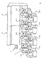
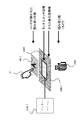
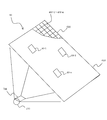
- FIG. 3 is a side sectional view of game device 10-1 according to the embodiment of the present invention. It is a schematic plan view of game device 10-1 according to an embodiment of the present invention.
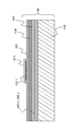
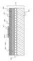
- FIG. 6 is a cross-sectional view of protective layer 610 and protective layer 611 of play field 60 of game device 10-1 according to the embodiment of the present invention.
- FIG. 6 is a conceptual diagram of the code
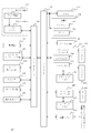
- It is a flowchart of the play processing of the game device 10-1 according to the embodiment of the present invention. It is a flowchart of the game processing of the game device 10-1 according to the embodiment of the present invention.
- FIG. 7 is a flowchart showing processing for detecting cards 80-1 to 80-n using ordinary paper media according to the embodiment of the present invention. It is a conceptual diagram which shows the relationship between the magnitude
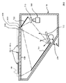
- FIG. 1 is a side sectional view of a game apparatus 10-1 having a configuration using a projector according to an embodiment of the present invention.
- FIG. 3 is a plan view of a play field of game device 10-1 having a configuration using a projector according to an embodiment of the present invention. It is sectional drawing of the play field 60 by the structure using the projector which concerns on embodiment of this invention.
- the game system X is a business video game machine (video game system) provided in a game facility such as a game center, a shopping store, or a sports facility.
- the game system X includes a plurality of game devices 10-1 to 10-n, a server 5, and a large display device 55.
- the game devices 10-1 to 10-n are connected to each other via a wired or wireless network, and a plurality of players can play a battle.
- the game system X may play a battle with other game apparatuses 10-1 to 10-n provided in other play facilities via the server 5 serving as a so-called “lobby” server. it can.
- the server 5 totals the score, sales, and remaining amount of cards to be paid out of the game devices 10-1 to 10-n. Further, the server 5 displays the game screens, rankings, operating statuses, and the like of the game devices 10-1 to 10-n on the large display device 55. Further, the server 5 can also be connected to a higher-level master server (not shown) to report the score ranking, sales, and the like.
- the server 5 can also download a program for the game devices 10-1 to 10-n, a firmware updater stored in the boot ROM 130, and the like from the master server, and update each device.
- the game apparatus 10-1 will be described as a representative example.
- game device 10-1 (game device) is similar to a conventional card game device, such as IC card reader / writer unit 220, card payout unit 230, switch 240, coin insertion unit 250, display 270, and the like. It has.
- a conventional card game device such as IC card reader / writer unit 220, card payout unit 230, switch 240, coin insertion unit 250, display 270, and the like. It has.
- the player P who is a user of the game apparatus 10-1 starts a game using the game apparatus 10-1 will be described.
- the player P sets up a set of cards such as a “starter pack” in which cards 80-1 to 80-n (playing media) used for playing a card game (playing media) and an IC card 85 are set. Purchase with a vending machine (not shown).
- the IC card 85 is used for storing data relating to the game.
- the cards 80-1 to 80-n are used for the player P to operate units, game characters, etc. in the actual game.
- a three-dimensional object such as a figure can be used as the game medium such as the cards 80-1 to 80-n.
- the player P when playing a game, the player P sets the IC card 85 in the IC card reader / writer unit 220. Then, the player P inserts coins into the coin insertion unit 250 or makes a settlement using a prepaid card or the like. Then, the player P places the cards 80-1 to 80-n on the play field 60 and moves them, or presses the switch 240 or the like to play the game. The progress of the game is displayed on the display 270. Further, it is displayed on the large display device 55 via the server 5. When the game is over, data relating to the game including the game results is written to the IC card 85.
- the card payout unit 230 outputs cards that can be used as the cards 80-1 to 80-n from the next time. At this time, the card payout unit 230 selects and outputs a card at random, for example.
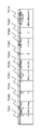
- the game device 10-1 includes a CPU 100 (control unit, game execution unit, area calculation unit), a storage unit 110, a boot ROM 130, a peripheral I / F 140 (peripheral device connection interface means), a bus arbiter 150, a graphic Processor 160 (drawing means), graphic memory 170, audio processor 180, audio memory 190, communication I / F 200, IC card reader / writer unit 220, card dispensing unit 230, switch 240, and coin insertion Unit 250, infrared camera 260 (first detection unit, image detection unit, imaging unit), display 270 (display unit), projector 275, speaker 280, and touch panel reading unit 300 (second detection unit, Contact detection unit).
- the CPU 100 includes a CISC (Complex Instruction Set Computer) system or a RISC (Reduce Instruction Set Computer) system CPU (Central Processing Unit), MPU (MicroDSP) (Digital Signal Processor), ASIC (Application Specific Processor), and the like.
- the CPU 100 is a control means having a calculation / control capability. Further, the CPU 100 can be provided with functions such as a storage unit 110, a graphic processor 160, and an audio processor 180 described later. Further, the CPU 100 uses the program 111 to acquire and correct the touched positions of the cards 80-1 to 80-n (FIG. 2), and the images of the codes 810-1 to 810-n (FIG. 11). Recognition can also be performed.
- the storage unit 110 includes high-speed storage means used for main storage such as RAM (Random Access Memory), HDD (Hard Disk Drive), flash memory, SRAM (Static Random Access Memory), magnetic tape device, optical disk device, and the like. Auxiliary storage means.
- the storage unit 110 includes a program 111 and data 112.
- the storage unit 110 includes an OS (Operating System, not shown) for causing the game apparatus 10-1 to function as a computer.
- the program 111 and the like can access each function of the game apparatus 10-1 through various APIs (Application Programming Interfaces) of the OS.
- the program 111 is a program for the CPU 100 to execute the card game of the game apparatus 10-1.
- the program 111 itself can be downloaded from the server 5 and updated, or downloaded at the start of the game.
- Data 112 is various data for the card game program 111.
- the data 112 includes data necessary for a card game, such as scenario data described later, data for each card, character display polygon data, music data, and the like.
- the data 112 can also store information such as difficulty level settings.
- the boot ROM 130 is a nonvolatile storage medium such as a ROM (Read Only Memory), a NOR flash memory, or an SRAM. Further, the boot ROM 130 sets the microcode of the CPU 100 when the game apparatus 10-1 is activated. The boot ROM 130 initializes each unit. In addition, the boot ROM 130 activates an OS or the like from the storage unit 110 and gives an instruction to execute the program 111.
- the boot ROM 130 includes a program and data for setting an IP address of the communication I / F 200, performing an operation test of each unit, and counting the number of coins and cards.
- the peripheral I / F 140 is a part that provides an interface such as USB, IEEE 1394, serial, parallel, infrared, and wireless for connecting to various peripheral devices (peripherals).
- an illumination unit 210 (light source unit, radiation unit), an IC card reader / writer unit 220, a card dispensing unit 230, a switch 240, A coin insertion unit 250 and an infrared camera 260 can be used.
- force feedback devices such as stick type controllers, acceleration detectors, vibration devices, foot / hand-operated switches, position detectors that detect the position on the screen of a display monitor, touchpad, touch panel, keyboard, mouse,
- a pointing device such as a trackball
- the peripheral I / F 140 can also control an electronic switch or the like. Accordingly, the peripheral I / F 140 can also suppress power consumption by turning on / off power of various peripheral devices.
- the bus arbiter 150 is an integrated circuit that provides a bus interface for connecting each part, such as a so-called “chip set”.
- the bus speed of each part connected by the bus arbiter 150 may be different, and may be asymmetric in up / down.
- the CPU 100, the storage unit 110, and the bus arbiter 150 are preferably connected by a high-speed bus such as FSB or HT.
- the graphic processor 160 and the bus arbiter 150 are connected by a broadband bus.
- the CPU 100 may include a bus interface such as a DDR2 / 3 SDRAM or an XDR DRAM so that the storage unit 110 can be directly read and written.
- the graphic processor 160 is a graphic processor having a function of drawing a three-dimensional CG.
- the graphic processor 160 includes a geometry unit 162 that calculates a polygon geometry (coordinates) and a rendering unit 164 that rasterizes / renders (draws) the polygon for which the geometry calculation has been performed.
- the graphic processor 160 includes a RAM DAC (RAM D / A converter) for outputting a rendered image to the display 270 and the projector 275, an HDMI interface, and the like. Further, the graphic processor 160 performs processing such as subtracting the image data of the play field sheet 620 (FIG. 8) previously captured from the infrared image data captured by the infrared camera 260 at high speed. As a result, the graphic processor 160 can remove noise from the image data and make the image data easy to perform image recognition.
- the graphic processor 160 can also perform image recognition itself of the codes 810-1 to 810-n (FIG. 11).
- the geometry unit 162 is a part for rotating and enlarging a matrix with respect to coordinates (world coordinates) of a polygon in a three-dimensional space. Further, the geometry unit 162 performs affine transformation or the like to obtain the coordinates of the polygon in the two-dimensional space.
- the geometry unit 162 can also include a “geometry shader” (or vertex shader) that performs tessellation such as polygon division and spline interpolation.
- the rendering unit 164 is a part that pastes image data called texture on the coordinate-calculated polygon and draws it in the graphic memory 170 with various effects.
- the polygons drawn by the rendering unit 164 include point polygons (points), line polygons (line lists), surface polygons such as triangles and quadrangles, and a collection of surface polygons.
- point polygons points
- line polygons line lists
- surface polygons such as triangles and quadrangles
- a collection of surface polygons when the rendering unit 164 performs rendering using ray tracing or the like, an object defined by a region such as a circle, an ellipse, a sphere, or a metaball can be rendered.
- the geometry unit 162 may be configured to be processed by the CPU 100. In this case, the CPU 100 executes a program stored in the storage unit 110 to create polygon coordinates. Then, the CPU 100 transfers the polygon coordinates to the graphic memory 170.
- the rendering unit 164 draws the polygon according to the polygon coordinates.
- the graphic memory 170 is a storage medium that can be read and written at high speed for the graphic processor 160 to draw.
- a broadband memory such as GDDR (Graphics Double Data Rate (graphics double data rate)
- this memory can be connected using high-level memory interleaving or the like.
- a configuration in which the graphic memory is built in the graphic processor 160 as in the system LSI is also possible. It is also possible to adopt a dual port configuration for displaying on a display monitor while the graphic processor 160 is drawing.
- the audio processor 180 is a DSP (digital signal processor) provided with a PCM (Wave) sound source for outputting music, voice, and sound effects.
- the audio processor 180 calculates a physical calculation sound source, an FM sound source, and the like.
- the audio processor 180 can also calculate various audio effects such as reverberation and reflection.
- the output of the audio processor 180 is D / A (digital / analog) converted and connected to a digital amplifier or the like. This output is reproduced by the speaker 280 as music, voice or sound effect.
- the audio processor 180 can also handle voice recognition of voice input from a microphone.
- the audio memory 190 is a storage medium that stores digitally converted data for music, voice, and sound effects. Of course, the audio processor 180 and the audio memory 190 can be integrally configured.
- the communication I / F 200 is an interface for connecting to a network such as a LAN (Local Area Network) or a WAN (Wide Area Network).
- the communication I / F 200 for example, WiMax (registered trademark), c. Link (registered trademark), HDMI (registered trademark), wired / wireless LAN, telephone line, mobile phone network, PHS network, power line network, IEEE 1394, etc. ) Can be used.
- WiMax registered trademark
- c. Link registered trademark
- HDMI registered trademark
- wired / wireless LAN telephone line
- mobile phone network PHS network
- power line network IEEE 1394, etc.
- the game apparatus 10-1 can communicate with other game apparatuses 10-2 to 10-n and the server 5.
- a battle game (a game that competes for a battle or the like; the same applies hereinafter) or a joint game (in cooperation with other players of the other game devices 10-2 to 10-n that are communicably connected).
- a game that solves the problem by connecting the plurality of game apparatuses 10-1 to 10-n so that they can communicate with each other, it is possible to collect game scores (scores, scores, etc., hereinafter referred to as scores) via the server 5.
- scores game scores
- the illumination unit 210 is a part that emits electromagnetic waves that are invisible to the naked eye and that is provided inside the housing 70 (see FIGS. 6 and 26) of the game apparatus 10-1.
- the illumination unit 210 is a part including an infrared lamp, an infrared LED array, an ultraviolet LED array, and the like, and a relay, an electronic switch, and the like (hereinafter described using an example of infrared rays).
- the illumination unit 210 may include a wavelength selection filter such as the first filter 711 in FIG. 6 in order to remove visible light components from the radiated infrared rays. Infrared rays are applied to the cards 80-1 to 80-n placed on the play field 60 in FIG.
- the illumination unit 210 also includes illumination for turning on an LED (not shown), a light, and the like outside the housing 70 and a switch for the illumination.
- the IC card reader / writer unit 220 is a known IC card reader or IC card writer for reading / writing information from / to the IC card 85 (FIG. 2).
- This IC card 85 stores personal results. Further, the IC card 85 stores the name, growth level, and the like of the character on the game associated with each of the cards 80-1 to 80-n. In addition, the IC card 85 can also write and store information on opponents to play, billing information, and the like.
- the IC card 85 includes a storage unit such as a non-volatile flash memory and a control unit such as an MPU.
- the IC card reader / writer unit 220 is activated by supplying power to the IC card 85 and writes it in the flash memory.
- the card payout unit 230 is a part for paying out (outputting) cards that can be used as the cards 80-1 to 80-n from the next time.
- information related to a game such as a unit or a game character is drawn on one side (for example, the front side).
- a code (such as codes 810-1 to 810-n in FIG. 11) using ink that reflects electromagnetic waves invisible to the naked eye such as infrared rays is printed.
- the card output by the card payout unit 230 can be replenished by the administrator of the game apparatus 10-1 by randomly arranging it in a keyed casing. This is the same as the coin insertion unit 250.
- the CPU 100 instructs the card payout unit 230 to pay out the card.
- the card dispensing unit 230 includes a printer using ink that reflects electromagnetic waves that are invisible to the naked eye such as infrared rays, and can print codes 810-1 to 810-n.
- the card payout unit 230 may print and output the encrypted issue date, issue location, ID (Identification), etc., on the codes 810-1 to 810-n when the card is output. it can.
- the number of cards to be paid out can be increased according to the game results.
- the type and number of cards to be paid out can be selected according to the game results (score, score, score, score, etc.).
- the switch 240 is a button, pad, joystick or the like.
- the switch 240 is used for various selections, menu calls, name inputs, and the like when playing a card game.
- the coin insertion unit 250 is a part (payment information detection unit) that detects a coin or a prepaid card that is inserted for a user to play a card game.
- the coin insertion unit 250 can transmit this signal when detecting a predetermined coin or amount.
- a predetermined coin or amount As this coin, an economic value medium such as an actual money or a medal used in an amusement facility can be used.
- the coin insertion unit 250 also includes a box for storing coins and the like. The administrator of game device 10-1 can access this box by opening case 70 (FIG. 6) using a key (not shown).
- the infrared camera 260 is a CCD camera or CMOS camera that can acquire image data by detecting electromagnetic waves that are invisible to the naked eye such as infrared rays (for example, light having a predetermined wavelength such as a wavelength of 0.7 to 2.5 ⁇ m). Imaging means (imaging unit). Moreover, in order to image only the electromagnetic waves (light) of a wavelength like infrared rays, you may provide the 2nd filter 712 of FIG. The infrared camera 260 captures infrared images reflected from the back of the cards 80-1 to 80-n placed in the play field 60 of FIG. 6 and creates image data.
- codes 810-1 to 810-n that are two-dimensional codes printed with invisible infrared reflective ink or the like on the back surfaces (back surfaces) of the cards 80-1 to 80-n.
- the CPU 100 and the graphic processor 160 can read the information described in the position and angle of each card and the code from the infrared image data captured by the infrared camera 260.
- the illumination unit 210 and the infrared camera 260 a configuration in which a code 810-1 to 810-n is read by incorporating an optical sensor in the liquid crystal element itself, such as “system liquid crystal”, is also possible.
- the display 270 is a display means (display unit) such as a liquid crystal display, a PDP (plasma display panel), or an HMD (head mounted display).
- the display 270 displays specific game developments, scores, and the like related to the arrangement of cards.
- the display 270 can also display a setting screen or the like.
- the projector 275 is a projection unit (projection unit) that projects a video (image).
- an optical projector such as a MEMS (Micro Electro Mechanical Systems), an LCOS (Liquid crystal on silicon), a transmissive high-temperature polysilicon LCD, or a laser can be used.
- the play field 60 (FIG. 2) includes a screen 635 (see FIG. 27) described later. Thereby, it is possible to use the projector 275 for the card game which projects an image.
- the speaker 280 is a part that amplifies the audio signal (audio information) output from the audio processor 180 with a digital amplifier or the like and outputs the audio.
- the speaker 280 may further include a microphone (not shown) for performing voice input.
- the touch panel reading unit 300 is a contact detection unit (contact detection unit) having a plurality of detection functions for detecting a plurality of touched points. That is, the touch panel reading unit 300 can detect a contact state when the touch panel reader 300 is touched.
- the touch panel reading unit 300 can be configured to include touch electrodes 400-1 to 400-n and sensor microcomputers 310-1 to 310-n.
- the touch electrodes 400-1 to 400-n are formed so as to be substantially transparent, and are formed so as to substantially transmit invisible electromagnetic waves (light having a predetermined wavelength) such as infrared rays from the illumination unit 210.
- the touch electrodes 400-1 to 400-n are capacitive touch panel switches, resistive film type touch switches, and the like.
- the touch electrodes 400-1 to 400-n can form conductive divided regions (areas) on a transparent substrate such as a sheet by using a manufacturing method described later.
- the sensor microcomputers 310-1 to 310-n are microcomputers (MPUs, sensor control units) or the like that acquire capacitance from the touch electrodes 400-1 to 400-n and detect contact.
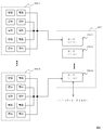
- the touch panel reading unit 300 includes, for example, touch electrodes 400-1 to 400-n formed by printing and sensor microcomputers 310-1 to 310-n. It is configured. Each of the touch electrodes 400-1 to 400-n includes a plurality of electrodes serving as a plurality of touch sensors. Each of the sensor microcomputers 310-1 to 310-n is connected to a corresponding electrode 401-1 to 401-n. Each of the sensor microcomputers 310-1 to 310-n scans each electrode according to an instruction from the CPU 100. In this scan, the sensor microcomputers 310-1 to 310-n obtain A capacitance value by A / D converting the capacitance of each electrode.
- the scanned capacitance value can be read out by the control means (control unit) such as the CPU 100 or the graphic processor 160 via the peripheral I / F.
- the control means detects which of the electrodes 401-1 to 401-n has changed the capacitance value upon reading. Thereby, a plurality of pieces of information such as coordinates touched on the play field 60 (FIG. 6) and the housing 70 (FIG. 6) can be detected simultaneously.
- the sensor microcomputers 310-1 to 310-n may be grouped as a sensor microcomputer array 301 on a chip-on-chip basis.
- a card touch sensor and a code reader can be combined. .
- the code of the card 80-1 can be read from the back side using a reader such as a camera.
- the print target of a game medium such as the card 80-1 may be a card or a three-dimensional object.
- the effect that touch detection and code reading can be made compatible is acquired.
- the type of detection target for example, a card
- there are some that affect the capacitance there are some that affect the capacitance. In view of this, it is possible to cope with this influence by detecting the type of the detection target with the code recognized from the infrared image and correcting the capacitance value.
- a play field 60 (a plane, a plane portion) is configured on the upper portion of the housing 70.
- the play field 60 includes, for example, a protective layer 610, a play field sheet 620, a touch panel sheet 630, and a glass plate 640.
- Each part is almost transparent to infrared rays.
- each is made up of members that are substantially transparent to infrared.
- the cards 80-1 to 80-n are disposed on the protective layer 610.
- the infrared rays are transmitted through the first filter 711 that transmits almost only infrared rays.
- the infrared rays hit the surface on which the codes of the cards 80-1 to 80-n (for example, the codes 810-1 to 810-n in FIG. 11) are drawn.
- the infrared rays reflected from the cards 80-1 to 80-n are narrowed down through the first reflecting plate 721 and the second reflecting plate 722.
- the narrowed infrared ray passes through the second filter 712 that allows only the infrared ray to pass therethrough.
- the infrared camera 260 can image this infrared ray.
- the touch electrodes 400-1 to 400-n (see FIGS. 8 and 9) printed on the touch panel sheet 630 make contact with the cards 80-1 to 80-n. Can be sensed.
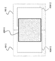
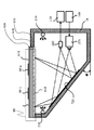
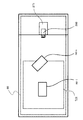
- FIG. 7 a schematic diagram of a plane drawn from the direction (upper surface) in which the user looks down in the vicinity of the play field 60 of the game apparatus 10-1 will be described.
- cards 80-1 to 80-n are arranged in the play field 60.
- the illumination unit 210, the first filter 711, the first reflector 721, the second reflector 722, the second filter 712, and the infrared camera 260 are arranged in a line.
- the display 270 can be installed above the second reflection plate 722 and on the housing 70.
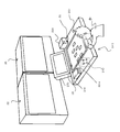
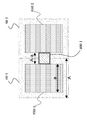
- FIG. 8 is a schematic diagram of the play field 60.
- cards 80-1 to 80-n are arranged on play field 60.
- the first filter 711 mainly the infrared light of the light source of the illumination unit 210 is irradiated on the back surface of the play field 60.
- the touch panel sheet 630 and the play field sheet 620 substantially transmit infrared light.
- infrared light is applied to the back of the cards 80-1 to 80-n.
- the code can be recognized by reading the infrared light reflected from the back of the cards 80-1 to 80-n.
- the game apparatus 10-1 can recognize the coordinates of the user's finger on the play field 60.
- a glass plate 640 is provided from below (backward) where infrared light is irradiated.
- the glass plate 640 is glass or the like that is transparent to invisible light such as infrared rays.
- a touch panel sheet 630 is provided above the glass plate 640.
- each of the touch electrodes 400-1 to 400-n is (i) a method in which a conductive paste containing extremely fine conductive particles is screen-printed on a transparent substrate (Japanese Patent Application Laid-Open No. 2007-142334, etc.
- a printing method such as gravure printing, or (ii) a method in which a metal foil such as copper is laminated on a transparent substrate, a resist pattern is formed on the metal foil, and the metal foil is etched (Japanese Patent Laid-Open No. 2008-2009). And the like, and a manufacturing method such as photolithography.
- the conductive pattern corresponding to each electrode of the touch panel sheet 630 is connected to sensor microcomputers 310-1 to 310-n (not shown).
- a play field sheet 620 is provided above the touch panel sheet 630.
- the play field sheet 620 transmits infrared light although a schematic diagram of the field is printed, as in the prior art.
- a transparent protective layer 610 is provided above the touch panel sheet 630.
- Cards 80-1 to 80-n are arranged above the protective layer 610 by the user during the card game play.
- the card 80-1 is arranged is shown.
- a code 810-1 is printed on the back surface of the card 80-1.
- the code 810-1 can be optically read by reflected infrared rays or the like.
- the touch panel sheet 630 may be positioned above the play field sheet 620. Further, the play field sheet 620 or the touch panel sheet 630 may be formed integrally with the protective layer 610. Further, when a projector or the like is used as described later, another layer for projecting video (image) may be provided.
- the protective layer 610 can include a conical protrusion as shown in FIG. Further, as shown in FIG. 10B, hemispherical protrusions can be provided. Such protrusions reduce friction. Therefore, the cards 80-1 to 80-1 to 80-n can be smoothly moved and played. Further, wear of the protective layer 610 can be suppressed. Further, since infrared light is diffused by the protrusions, erroneous recognition of the codes 810-1 to 810-n due to scratches on the protective layer 610 can be reduced. Referring to FIG. 10 (a), the end portion 611 of the cone is formed flat rather than as a complete protrusion.
- the diameters of the conical trunk portion 612 and the end portion 611 can be formed such that moire patterns are not easily generated when the codes 810-1 to 810-n are recognized.
- the hemispherical portion 613 in FIG. 10B By forming the hemispherical portion 613 in FIG. 10B to be hemispherical, it is possible to further reduce irritation to the user's hand. Moreover, the effect that it is easy to remove dirt at the time of wiping off is also acquired.
- the diameter of the hemisphere can also be formed so as not to cause a moire pattern.
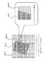
- the cord 810-1 has a structure in which several circumferential bands extend from the central axis 820.
- the code 810-1 can distinguish between a place where the brightness of infrared reflection is high (white) and a place where the brightness is low (black). Various information can be described by this black and white pattern.
- the code 810-1 is arranged in a circle, so that the position (coordinates) and orientation (angle) of the card on the play field 60, and the boundary between the card and other locations can be accurately recognized. Can be grasped. As a result, the touch panel and the code can be read simultaneously.
- the position pressed (contacted) can be accurately grasped.
- the manufacturing cost of the touch electrodes 400-1 to 400-n and the cost of the arithmetic device for recognition can be suppressed.
- the black and white pattern of the code 810-1 for example, information can be described using a gray code. Thereby, the influence at the time of misrecognition can also be suppressed.
- the code 810-1 is not limited to a black and white pattern, and for example, information can be described using coordinate information based on a predetermined pattern or a dot pattern meaning a code. Thereby, it is also possible to increase the amount of information to the game medium.
- the pattern can have a plurality of values depending on the reflection frequency of invisible light such as infrared rays.
- the card type includes information on a special “kira card” described later.
- the information described in the code 810-1 includes information as to which position of the card is touched and whether or not a “special attack” or the like as described later can be performed.
- the information described in the code 810-1 includes an ID for distinguishing the same type of card by a serial number or the like.
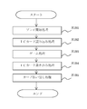
- FIG. 12 Player processing of game device 10-1
- a player P who is a user of the game apparatus 10-1 in FIG. 2 specifically uses the game apparatus 10-1 to play a card game.
- a control unit such as the CPU 100 mainly executes a specific process using hardware resources such as the program 111 and data 112 stored in the storage unit 110.
- Step S101 the CPU 100 performs a play start process.
- the CPU 100 detects whether the IC card 85 is inserted using the IC card reader / writer unit 220 via the peripheral I / F 140.
- the CPU 100 uses the coin insertion unit 250 via the peripheral I / F 140 to detect that a payment has been made by inserting a coin or using a prepaid card.
- the process proceeds to step S103.
- the CPU 100 displays a screen for instructing insertion of coins or a prepaid card on the display 270 or outputs audio from the audio processor 180 to the speaker 280.
- the CPU 100 When payment is made without the IC card 85 being inserted, the CPU 100 prompts the user to insert the IC card 85 and notifies that the starter pack of the IC card 85 needs to be purchased. In a state where the IC card 85 is not inserted and payment is not performed, the CPU 100 can display a demonstration screen on the display 270 to attract the interest of the player. At this time, the CPU 100 can make the player know that the game apparatus 10-1 is not being played by not outputting sound.
- Step S102 the CPU 100 performs an IC card reading process.
- the CPU 100 reads the data of the IC card 85 using the IC card reader / writer unit 220 via the peripheral I / F 140.
- the IC card 85 is a contact type or non-contact type IC card.
- the IC card 85 includes a flash memory (storage unit), an MPU (control unit), and the like, and can encrypt and store data relating to the game.
- data relating to this game as will be described later, data such as the level of each character of each card 80-1 to 80-n, military funds in the game, territories controlled, ranking, etc. can be stored. .
- the play level of the player P and the like are also stored.
- game-related information, player-related information, and the like can be stored.
- the game-related information relates to a game such as a scenario number in progress in the “campaign mode”, the number of territories in control, and whether the play of the player P has cleared a plurality of game scenarios.
- the player-related information relates to the player such as how many pieces of powerful ability value data are possessed among the cards 80-1 to 80-n and the winning percentage of play in the card game.
- the CPU 100 can change selectable scenarios according to the level of play.
- the CPU 100 can end the play process without proceeding to the next step S103. .
- the CPU 100 transmits data of “IC card failure / illegal” to the server 5.
- the CPU 100 can instruct the speaker 280 to sound a siren or the like from the audio processor 180 and prompt a call to a clerk (staff) of the amusement facility.
- the CPU 100 can also pay back coins from the coin insertion unit 250.
- Step S103 the CPU 100 performs a game process that specifically executes the game.
- the CPU 100 executes a part of the program 111 in the storage unit 110 that performs a specific game process.
- a game device 10-1 according to an embodiment of the present invention executes a tactical class real-time simulation game (real-time strategy) that deals with battles of the Sangokushi-style era.
- the flow of this real-time simulation game is as follows. First, the CPU 100 reads out a game scenario according to the user's selection of a game mode or the like.
- the CPU 100 gives an instruction using AI (artificial intelligence), or the opponent gives an instruction via the network.
- AI artificial intelligence
- the player P places cards 80-1 to 80-n, selects (contacts) the cards 80-1 to 80-n, and switches 240
- An instruction is given by selecting a command or the like. Instructions to these enemy units, neutral units, and friendly units are calculated by the CPU 100 in units of “frames” every 1/60 seconds, for example, and reflected in the progress of the game in real time.
- the CPU 100 increases or decreases the personnel of the unit, or causes a change that the position on the map belongs to a friendly unit or an enemy unit. Further, the CPU 100 causes the graphic processor 160 to draw this change on the display 270. Further, the CPU 100 uses the audio processor 180 to output sound effects and BGM (background music) from the speaker 280.
- the CPU 100 ends the game process when a scenario ending condition such as a unit personnel, arrangement, or position affiliation is satisfied or a predetermined time elapses.
- the game system X is a so-called multi-platform. That is, the game apparatus 10-1 can select and play a plurality of types of games. At this time, it is possible to describe the types of games that can be played on the IC card 85 and to download and execute the program 111 itself from the server 5 in accordance with the selection of the player P. Further, when the player P is playing a game, the play content can be displayed on the large display device 55 via the server 5 of FIG. 1 to enjoy a more powerful play.
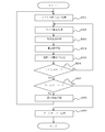
- the game process will be described in detail with reference to FIG.
- Step S301 First, the CPU 100 performs a scenario reading process.
- the player P in FIG. 2 selects a game mode.
- the buttons and switches 240 of the software keyboard drawn in the play field 60 are used.
- a mode such as “campaign mode”, “national conquest mode”, “matching mode”, “scenario selection mode”, “tutorial”, etc. can be selected.
- “Campaign mode” wins the prepared scenarios in order.
- “Nationwide conquest mode” selects a scenario for each country by selecting the “country” to attack.
- a scenario is selected between the player P and the other game apparatuses 10-2 to 10-n to play a battle.
- scenario selection mode a scenario that has finished (cleared) a scenario can be selected.
- “Tutorial” teaches how to play the game for beginners.
- the CPU 100 reads a scenario corresponding to each game mode in accordance with the instruction of the player P.
- This scenario may be stored as a part of the data 112 in the HDD of the storage unit 110 or the like. Further, the scenario may be configured to be downloaded from the server 5.
- map data As the contents of the scenario data, map data, unit placement data, end condition data, special weapon data, and the like can be used.
- the map data is 3D data (virtual three-dimensional space information) of a map that becomes a battlefield.
- the map data is subjected to projection conversion, viewpoint change, shading (shaded) processing and the like in real time using the graphic processor 160, and is displayed on the large display device 55 from the server 5 via the display 270 or the network.
- the map data includes data such as height and terrain attributes. In the data such as the height and the terrain attribute, it is possible to specify terrain data such as swamps and pits related to the advancing speed of the unit and steep slopes where the unit cannot proceed. Further, the “location” data is stored on the map data.
- Enemy units and friendly units move to the coordinates and take the “flag” to control the “base”.
- objects such as castles, stone walls and moats can be arranged at each base.
- the unit arrangement data can be stored by determining the arrangement of enemy units and allies on the map data, the timing of reinforcement, the scenario end condition, and the like.
- the end condition data can be stored by setting the annihilation of the enemy unit or the friendly unit as a condition.
- various conditions can be determined and stored, for example, when a predetermined position is controlled, when a leader of a specific unit is defeated, or when a predetermined “deadly move” is activated.
- the CPU 100 starts a process related to a specific game play.
- Step S302 The CPU 100 performs card detection processing for detecting the arrangement and contact state of the cards 80-1 to 80-n. As described above, this process is to detect an instruction for the player P in FIG.
- game device 10-1 according to the embodiment of the present invention uses the arrangement state and contact state of cards 80-1 to 80-n. Using the state of placement and the state of contact is not a mere combination. Thereby, unlike the prior art, various instructions that can improve game performance can be detected. First, in the following, with reference to FIGS. 14 to 20, a detailed description will be given of how to detect the code and specify the touch position for each of the cards 80-1 to 80-n.
- the code When detecting the code, the code is detected by reading the codes 810-1 to 810-n using infrared rays or the like. When the touch position is specified, the touch position is specified by touching the touch electrodes 400-1 to 400-n.
- this card detection process (1) a process for detecting cards 80-1 to 80-n using ordinary paper media, and (2) a special “kira card” (capacitance that is contained in metal foil or the like) The description will be divided into processing for detecting cards 80-1 to 80-n including game media having different values. Which process (1) or (2) is selected can be selected according to the type of card game.
- the CPU 100 stores and selects in the nonvolatile memory of the storage unit 110.
- the touch electrodes 400-1 to 400-n are capacitance electrodes formed on the touch panel sheet 630 by printing or the like (see FIGS. 4 and 8).
- the touch electrodes 400-1 to 400-n are connected to the sensor microcomputers 310-1 to 310-n by wiring. Therefore, “multi-touch”, that is, a plurality of pieces of information touching each electrode can be acquired at the same time. Further, by processing and using the image acquired by the infrared camera 260, it is possible to detect the position of the card and the contact position with higher accuracy.
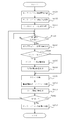
- Step S1021 the CPU 100 of the game apparatus 10-1 performs sensor microcomputer operation start processing.
- the CPU 100 controls the electronic switch from the peripheral I / F 140.
- the CPU 100 supplies power to the sensor microcomputers 310-1 to 310-n.
- the sensor microcomputers 310-1 to 310-n can be operated only during the game process. Therefore, an effect that the operating cost of the game apparatus 10-1 can be reduced is obtained.
- Step S1022 the CPU 100 performs a sensor microcomputer communication connection process.
- the CPU 100 checks whether communication connection is possible between the sensor microcomputers 310-1 to 310-n and the CPU 100 via the peripheral I / F 140. If any of the sensor microcomputers 310-1 to 310-n does not respond as a result of this check, it is assumed that a failure has occurred. At this time, the CPU 100 transmits to the server 5 via the communication I / F 200. Also, a siren or the like is sounded to notify the administrator of the game apparatus 10-1. If all the sensor microcomputers 310-1 to 310-n have responded, the CPU 100 advances the process to step S1023.
- Step S1023 the CPU 100 performs sensor microcomputer initialization processing.
- an initial signal or the like is transmitted to the sensor microcomputers 310-1 to 310-n.
- each of the sensor microcomputers 310-1 to 310-n starts the initialization process from the initial position of the built-in ROM or the like.
- the sensor microcomputers 310-1 to 310-n perform processing such as connection confirmation and calibration for the connected touch electrodes 400-1 to 400-n.
- each of the sensor microcomputers 310-1 to 310-n transmits log data as a result of the initialization process to the CPU 100.
- the CPU 100 can notify the administrator of the game apparatus 10-1 by transmitting it to the server 5 via the communication I / F 200 and sounding a siren or the like. Thereafter, when the initialization process is normal, each of the sensor microcomputers 310-1 to 310-n waits for a detection start signal from the CPU 100. In the following, detection of card contact after the card game is started will be described using the sensor microcomputer 310-1 as a representative example of the sensor microcomputers 310-1 to 310-n.
- Step S1024 the sensor microcomputer 310-1 determines whether a detection start signal is received from the CPU 100. This detection start signal is transmitted by the CPU 100 after the card game is started. With this detection start signal, as described above, the sensor microcomputers 310-1 to 310-n can detect contact of the cards 80-1 to 80-n at about 60 times / second. If the determination in step S1024 is Yes, the sensor microcomputer 310-1 advances the process to step S1030. Conversely, if the determination in step S1024 is No, the sensor microcomputer 310-1 returns the process to step S1024.
- Step S1025) the sensor microcomputer 310-1 performs a scanning process. Specifically, the capacitance is sequentially measured from each electrode of the touch electrode 400-1 scanned by the sensor microcomputer 310-1, and subjected to A / D conversion or the like to obtain a capacitance value (touch count value). Get. With this capacitance value, a value as to whether each electrode is turned on / off can be obtained. Moreover, the value about the touch contact pressure (contact area) can be obtained.
- the sensor microcomputer 310-1 writes the capacitance values in the storage unit 110 by DMA transfer or the like via the communication I / F 200. Further, the CPU 100 can directly acquire the capacitance value and store it in the storage unit 110. Thereby, the scanning process is terminated.
- Step S1026 the CPU 100 performs an electrode coordinate acquisition process.
- the CPU 100 acquires the coordinates of the electrode touched (pressed) by the user from the capacitance values acquired from the sensor microcomputers 310-1 to 310-n.
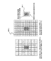
- the relationship between the size of each electrode and the coordinate acquisition of the pressed (contacted) electrode will be described in detail with reference to FIGS.
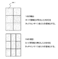
- the inventor of the present invention repeated diligent experiments and research to use it specifically in games. Then, if there is an area of an effective area of about 70% with respect to the area of the card 80-1 that is an assumed detection target, the position of the card 80-1 can be accurately determined at high speed together with the subsequent recognition of the infrared image. I found that I can identify it. That is, the size of one electrode of the touch electrode 400-1 can be about 70% of the size of the card 80-1. Even when a figure or the like is used as a game medium instead of the card 80-1, for example, the area of the effective area such as 70% with respect to the area of the grounding surface on which an optical code such as a two-dimensional code is printed. Can be used.
- the size of one electrode is set using an effective area sufficient to detect each of cards 80-1 to 80-n from detection target card 80-1.
- a region per location of the touch electrode 400-1 is defined as length c ⁇ length d.
- a method of obtaining the length c and the length d will be described with reference to FIGS. 17A and 17B.
- a positional relationship in which the sensor just straddles adjacent cards that are in close contact with each other is a “worst condition” in which it is difficult to detect the position of contact. That is, when determining whether the electrode is “ON” from the capacitance value of the touch electrode 400-1, it is not possible to determine which of the card 80-1 and the card 80-2 is in contact. For this reason, in order to specify the card being touched, the size per electrode needs to be within the range of the “dead zone” that is an area outside the effective area.
- the area of the touch sensor can be set to a size in which the shorter one of the horizontal width c and the vertical width d is a diagonal line.
- the inventor of the present invention has conducted intensive experiments and researches.
- the electrodes of the touch electrodes 400-1 to 400-n are arranged with the maximum cost performance, 70 in the area to be detected.
- the effective region is about%. That is, touch electrodes (switches) can be provided to the minimum necessary for one of the cards 80-1 to 80-n. Therefore, when the effective area is set to 70% in this way, it is possible to detect the contact coordinates of the cards 80-1 to 80-n at a reduced cost.
- the sizes of the touch electrodes 400-1 to 400-n can be obtained based on an area obtained by equally dividing the area of the card 80-1 to be detected.
- an area of 1/6 or 1/9 of the cards 80-1 to 80-n is the equally divided area.
- the size obtained by dividing the card area into 6 equal parts is the size of one electrode of the electrode 400-1.
- the size obtained by dividing the card area into nine equals is the size of one electrode of the electrode 400-1.
- each of the touch electrodes 400-1 to 400-n it is preferable to arrange the electrodes so as to cover 70% of the cards 80-1 to 80-n.
- the contact position of each card 80-1 to 80-n is detected in detail so that the area is 1/6 or 1/9 of the area of the card 80-1 to 80-n. It is.
- Step S1027) Here, with reference to FIG. 14 again, (1) processing for detecting the cards 80-1 to 80-n using ordinary paper media will be described.
- the CPU 100 performs infrared image card position acquisition processing.
- the infrared camera 260 receives images printed on the back surfaces of the cards 80-1 to 80-n using infrared rays as shown in FIG.
- the CPU 100 analyzes the received image using the graphic processor 160 and the like, and recognizes codes 810-1 to 810-n as shown in FIG. As a result, it is possible to obtain operation information values for the coordinates (position), angle (direction), ID (card type), etc. on the play field 60 of the cards 80-1 to 80-n.
- the CPU 100 stores operation information values such as coordinates, angles, and IDs of the respective cards 80-1 to 80-n in the storage unit 110.
- operation information values such as coordinates, angles, and IDs of the respective cards 80-1 to 80-n in the storage unit 110.
- Step S1028) the CPU 100 performs card information acquisition processing.
- this card information -Position where the user touches on the play field 60 (contact information)
- -Acquire information such as the number of cards 80-1 to 80-n on the play field 60, ID, coordinates, angle, and touch information.
- the CPU 100 acquires information regarding that the cards 80-1 to 80-n on the play field 60 are touched, that is, touched, as touch information.
- touch information it is possible to use information such as a flag indicating whether the card is touched, the strength being touched, and the coordinates being touched.
- the touched coordinates are corrected based on the card image processing. Specifically, the correction is made based on the coordinates and angles of the cards 80-1 to 80-n and the coordinates of the contacted electrodes. As described above, the coordinates and angles of the cards 80-1 to 80-n are acquired by the infrared image card position acquisition process.
- the coordinates of the contacted electrode are acquired by the electrode coordinate acquisition process described above.
- the CPU 100 sets the position in the card as the contacted coordinates.
- the CPU 100 determines that the card 80-1 to 80-n is in contact with the contacted coordinates. To do.
- the capacitance value of the contact of the two to four electrodes indicates a close value, the CPU 100 is contacted with the coordinates of the electrodes closer to the cards 80-1 to 80-n. Coordinates. Also, temporal correction is possible.
- the touched coordinates can be updated in 1/60 seconds, for example. Therefore, when the electrode to be contacted moves, the CPU 100 selects which card 80-1 to 80-n has been contacted based on the amount of movement. Then, the CPU 100 sets the coordinates of the selected cards 80-1 to 80-n as touched coordinates. As described above, when the cards 80-1 to 80-n are in contact with each other, the CPU 100 can store the corrected coordinates in the touch information. In addition, the touched information in the card can also be stored in the touch information.
- Step S1029 the description returns to the operation of the sensor microcomputer 310-1.
- the sensor microcomputer 310-1 determines whether the detection of the contact with the card has been completed. Specifically, the sensor microcomputer 310-1 determines whether a detection end signal has been received from the CPU 100. Note that the CPU 100 can transmit this detection end signal at the end of the game process in step S103 of FIG. If the determination in step S1029 is YES, the sensor microcomputer 310-1 advances the process to step S1030. Conversely, if the determination in step S1029 is No, the sensor microcomputer 310-1 returns the process to step S1024, and repeats the process below the scan process, for example, every 1/60 seconds.
- Step S1030 When the detection ends, the CPU 100 performs a sensor microcomputer operation stop process. Specifically, when the sensor microcomputer 310-1 receives the detection end signal, the sensor microcomputer 310-1 enters a mode in which the operation is stopped to reduce power consumption, such as a HALT state. In addition, the CPU 100 controls the electronic switch from the peripheral I / F 140 to turn off the sensor microcomputers 310-1 to 310-n. Thereby, power consumption can be suppressed while the game is not being played, and malfunctions can be reduced. Thus, (1) the processing for detecting the cards 80-1 to 80-n using ordinary paper media is completed.
- a “kira card” is a card in which metal foil or the like is scattered like “lame” on the surface or inside, or foil printing such as an aluminum layer is performed. “Kira Card” is often used as a special valuable card in card games. In other words, this “kira card” has a low resistance due to the use of metal foil. When the “kira card” bridges between the electrodes straddling, it is detected including the capacitance between both electrodes, and as a result, the detected capacitance increases.
- step S1031 performs the same process as step S1021
- step S1032 performs step S1022
- step S1033 performs step S1023
- step S1034 performs the same process as step S1024.
- Step S1035) the CPU 100 performs infrared image card position acquisition processing. This process is also the same as step S1027 in FIG. As a result, the CPU 100 first determines the coordinates (position), angle (orientation), ID (card type), etc. on the play field 60 of the codes 810-1 to 810-n on the back of the cards 80-1 to 80-n. Get the value of. And CPU100 can determine whether it is a killer card by ID by subsequent processing, and can perform a correction process.
- Step S1036 the CPU 100 determines whether there is a glitter card. Here, it is determined whether or not there is a glitter card among the cards 80-1 to 80-n on the play field 60 of FIG. If the determination in step S1036 is Yes, the CPU 100 advances the process to step S1037. Conversely, if the determination in step S1036 is No, the CPU 100 advances the process to step S1039 and performs normal scan processing.
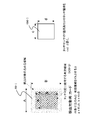
- Step S1037) The CPU 100 performs a kill card area calculation process. This will be described with reference to the conceptual diagram of FIG.
- each of the touch electrodes 400-1 to 400-n has a large capacitance value by a value proportional to the area where the glitter card and the electrode overlap.
- the touch switch calculates the sensitivity value from the relationship of the capacitance with the object on the electrode, the sensitivity value proportional to the area covering the electrode changes when the killer card is placed.
- game device 10-1 identifies the card position by recognizing codes 810-1 to 810-n. That is, the game device 10-1 recognizes the codes 810-1 to 810-n by image recognition, so that the specified position coordinates of the card can be used. Thereby, it is possible to calculate the area covering each electrode by combining the position coordinate information and electrode position information of the specified card. In other words, by using the calculated area and subtracting the increment of the sensitivity value in advance to perform the touch calculation, malfunctions of the electrodes 400-1 to 400-n can be suppressed.
- the overlapping area is calculated for each electrode overlapping the card 80-3. Since the position of the electrode is known in the play field 60, the known coordinate is stored in the storage unit 110, and the intersection of the card and the electrode is calculated to calculate the area of the overlapped portion. Can do. For example, in the example of FIG. 20, since the electrodes of the touch electrode 400-1 do not overlap, calculation is not performed. In contrast, since the electrodes of the touch electrode 400-9 are overlapped, the area of the overlapped portion can be calculated.
- Step S1038) the CPU 100 performs an electrode sensitivity value correction process.
- the “offset value” of the capacitance value of each electrode is calculated from the area of the overlapping portion of each electrode obtained in the above-described Kira card area calculation process.
- the coefficient can be stored in the storage unit 110 as a predetermined constant by previously obtaining the relationship between the capacitance and area of a normal card and a Kira card.
- the CPU 100 also stores the obtained offset value of each electrode as an array variable or the like corresponding to each electrode.
- step S1039 processing similar to that in step S1025 is performed, and each of the sensor microcomputers 310-1 to 310-n performs scanning processing.
- Step S1040 the CPU 100 performs electrode coordinate acquisition / offset processing.
- the CPU 100 performs an electrode coordinate acquisition process similar to step S1026. That is, the CPU 100 reads out the capacitance values acquired from the respective sensor microcomputers 310-1 to 310-n from the storage unit 110. Then, the CPU 100 reads out the offset value of each electrode described above from the storage unit 110 and performs a process of adding or subtracting it to the capacitance value corresponding to each electrode. As a result, it is possible to cancel the malfunction due to the glitter card and to accurately detect the contact of the cards 80-1 to 80-n. Thereafter, the CPU 100 erases the array of offset values of each electrode by performing zero fill or the like.
- Step S1041 performs the same processing as Step S1028, Step S1042 performs Step S1029, and Step S1043 performs Step S1030.
- Step S1041 performs the same processing as Step S1028, Step S1042 performs Step S1029, and Step S1043 performs Step S1030.
- the touch position acquisition by each of the sensor microcomputers 310-1 to 310-n and the processing of the image acquired by the infrared camera 260 are used, it is possible to detect the position touched by the user in the play field 60.
- the resolution can be set to, for example, 400 points or more over the entire play field 60.
- each of the cards for play 80-1 to 80-n has a size of about 86 mm ⁇ 54 mm, it is possible to obtain a resolution that can be divided into six without requiring much cost. It is also possible to have a resolution for obtaining points that can be divided into nine.
- game device 10-1 it is possible to detect a contact position of 60 points / second or more for 400 points in play field 60.
- This is a sufficiently high speed as compared with the conventional technique for optically detecting only the code. That is, when the user touches the cards 80-1 to 80-n, the contact position can be detected at a very high speed almost in real time.
- the drawing speed of a moving image that can be perceived by the human eye is about 60 frames / second. Further, the 60 frames / second is also a drawing speed generally used in games. Therefore, the drawing speed, the code detection speed, and the contact position detection speed can be matched.
- the reaction of the game apparatus 10-1 is delayed (heavy) than the instruction of the player P in the game.
- the game situation greatly depends on the speed of instructions for the placement of each unit. For this reason, the reaction speed is very important in the fun and operability of the game. Therefore, by providing a sufficient detection speed as in the card detection method according to the embodiment of the present invention, a great effect of improving the operability of the card game can be obtained.
- Step S303 Here, referring again to FIG. 13, the specific processing of the card game after card detection will be described in detail.
- the CPU 100 performs a teammate process. In this ally unit process, the CPU 100 obtains various instructions regarding the arrangement of the cards 80-1 to 80-n of the player P in FIG.
- the CPu 100 performs a process for causing each character in the team to act. As this action, move to the destination or battle with enemy units.
- the enemy unit is operated by the CPU 100 and other players. The results of these processes are reflected by the drawing process after the next enemy unit process.
- the friendly unit process in step S302 will be described in more detail.
- each unit has data of a unit such as a friendly unit, an enemy unit, and a neutral unit, and the game progresses according to the state of the unit.
- FIG. 22 shows an example of data elements related to a teammate.
- elements of this data elements such as a unit number D101, a leader number D102, a command D103, a special attack level D104, a target D105, a morale D106, and a member D107 can be provided.
- the unit number D101 is a part (unit number storage unit) that stores a number used on the program corresponding to each unit.
- the leader number D102 is a part for storing a number indicating the character of the military commander of the cards 80-1 to 80-n associated with the unit number (a military command storage unit).
- the command D103 is a part (behavior information storage unit) that stores data of a command of a unit action determined by the unit action instruction process.
- the special attack level D104 is a part (special attack level storage unit) that stores a “special attack level” used for a special attack described later.
- the target D105 is coordinates on the map or a part (coordinate information storage unit) indicating a unit to be pursued. This target D105 can be determined by the arrangement of the corresponding cards 80-1 to 80-n.
- the morale D106 is a part (morale parameter storage unit) that stores parameters related to morale. Morale is a value related to the strength of a unit's battle, ease of turning over, ease of attack, and the like.
- the member D107 is a part (member character storage unit) that stores a list of member characters. This member is variable except for the leader. Therefore, for example, an operation of joining units and distributing them with other units is possible. Further, it is possible to perform operations such as acquiring and increasing the number of characters laid down from enemy units. It is also possible to operate different characters such as archers and cavalry as the same unit. It should be noted that data such as the number of morale D106 and member D107 and the type of character can be stored in the IC card 85.
- Data elements related to each character may include elements such as member number D201, name D202, HPD 203, LVD 204, occupation D205, skill D206, gender D207, ability value D208, leader D209, item / equipment D210, and the like.
- the member number D201 is a number associated with each member character. This number can be added by the CPU 100 according to the program every time the card game is played.
- the name D202 is an element indicating the name of the character. This name is set to a default name in the case of a leader character. Also, the player P in FIG. 2 can give a name. Such a leader character name can be stored in the IC card 85.
- the name of the character other than the leader can be set from a predetermined name list by the CPU 100 using a program every time the card game is played.
- the HPD 203 is an element indicating the physical strength value of the character. When HP reaches 0, the character dies. The HP value can be restored to the user's support or automatically when in a particular location, such as a castle or other position on the map. Also, when the leader's HP becomes 0, the leader cannot be used as “uncombatable” while the game is being played. During recovery, a parameter on the card game called “Hyogi” decreases.
- the LVD 204 is an element indicating a level such as character strength. The level of the leader increases depending on the number of times played and the number of special attacks.
- the occupation D205 is an element indicating “occupation” related to the appearance, skill, etc. of the character on the polygon drawing.
- leaders such as military commanders, soldiers, and ninjas.
- special categories such as “future person”, “makaijin”, and “android” may be prepared for the above-mentioned Kira card.
- the occupation for leaders can have occupational attributes such as Daimyo, territory, villager, first leader, monarcher chief, and Shinobu.
- the occupations of characters other than the leader in the same unit can be used mainly for the characters constituting the unit, such as cavalry, archer, mercenary, and foot.
- This profession can be set according to the ratio when distributing the forces that can be moved on the scenario by the user to each unit after the scenario reading process.
- the occupation ratio of the soldiers of the unit can be stored in the IC card 85 for each leader. And according to the progress of the card game, you can also set the occupation of soldiers at this rate.
- the skill D206 is an attribute possessed only by the leader and stores a special attack method to be executed at the time of a special attack.
- This skill D206 can be increased with the value of the level D204 of the leader character. You can also “learn” the skills of enemy leaders.
- the sex D207 is a value related to the sex such as male, female, and neutral, and the character of the character. Depending on this gender and personality, values such as the ability to execute instructions by the user and the diverseness toward the enemy units change during the game. The value of this attribute of the leader also affects the attribute values of characters other than the leader.
- the ability value D208 is an attribute indicating the ability assigned specifically for each character. The attribute value of the ability value D208 can be expressed by an increase or decrease from a predetermined value at the same level. For example, a character with a member number D201 of 100 in FIG.
- the 23 has an AG (Agility) value of +50 and a DF (Defense) value of +20. This ability value can be changed by the value of other attributes such as occupation D205 and item / equipment 210.
- the leader D209 is a flag indicating whether or not the character is a leader. Of course, it is possible to adopt a configuration in which the leader character and other characters have different data.
- the item / equipment D210 is an attribute that indicates an item that the character equips or equips. It also remembers the attribute of whether or not equipped. Further, the value of the other attribute also changes depending on the attribute value of the item / equipment D210. It is also possible to store the data of each character for the player P in the server 5 and download and use it for each play.
- Step S2011 the CPU 100 performs card unit handling processing. Specifically, the CPU 100 searches the acquired card information, and associates the cards 80-1 to 80-n arranged in the play field 60 with the ally unit that performs processing.
- the card 80-1 is associated with a unit whose unit number D101 to be processed is 1.
- the CPU 100 associates the coordinates of the play field 60 of the card 80-1 with the coordinates on the map of the corresponding card game. As a result, the “movement position” on the map instructing the unit performing the processing can be acquired.
- the CPU 100 stores this movement position in the target D105 of the unit performing the process. Further, when an enemy unit exists at a position on the map, the enemy unit can be stored in the target D105. Then, the CPU 100 calculates how far these coordinates have moved from the position in the previous frame. Thereby, it is possible to acquire “acceleration” instructing the unit performing the processing.
- the card 80-1 to 80-n arranged in the play field 60 and the unit performing the processing cannot be associated with each other for a predetermined number of seconds, the card is assigned to the play field 60. Judged to have been removed from. In this case, it is determined that the player P has given an instruction to move to the coordinates where the reserve unit such as “castle” is arranged for the unit to be processed. Alternatively, it may be determined that an instruction to “retreat” is given outside the screen.
- Step S2012 the CPU 100 performs card contact time acquisition processing. Specifically, the CPU 100 determines whether the card is in contact with the flag or the pressed strength (contacted) from the touch information of the card information of the card 80-1 associated with the unit to be processed. Pressure, contacted area, etc.). In this process, the CPU 100 detects whether the card is touched or the strength of the touch regardless of the position in the card.
- contact time pressing time
- the contact time is the time until the card is separated from the contact (non-contact).
- the CPU 100 increases the special attack level D104 of the ally unit to be processed according to the contact time. Depending on the value of this special attack level D104, the damage (power) given to the enemy in a “special attack” described later changes. Further, it is possible to detect an operation of intermittently touching and releasing (operation of repeating contact / non-contact) such as “tapping”. This is used for an instruction such as “special action” described later.
- Step S2013 the CPU 100 performs card contact position acquisition processing. Specifically, the CPU 100 acquires the coordinates touched in the card 80-1 from the touch information of the card information of the card 80-1 associated with the unit to be processed. As will be described later, the coordinates being touched are used for action instructions to the unit in combination with the contact time described above.
- Step S2014 the CPU 100 performs a unit action determination process. Specifically, as the action of the unit, first, when the “movement position” acquired in step S2011 described above is different from the coordinates on the current map, the CPU 100 determines to perform the movement action.
- the movement action is an action of a unit that moves each character so as to move the unit to the coordinates of the movement position.
- the special attack level D104 is sufficiently high and a special attack is possible, and the player P in FIG. 2 applies a strong contact pressure (increases the contact area) or moves a predetermined distance or more.
- the CPU 100 determines an action for performing a “special attack” described later.
- the CPU 100 when the user performs processing such as touching and releasing the card 80-1 associated with the unit being processed with little movement, the CPU 100 basically performs an attack instruction. Make a decision to do. That is, a decision is made to instruct the archer to perform a bow attack at that position or to instruct the gun corps to attack with a gun. At this time, if a tap has been detected, an attack instruction such as “special action” is determined. Further, when an attack instruction is issued when the teams are at coordinates closer than a predetermined distance, the CPU 100 can make a decision to perform a special attack such as a “linked attack” that attacks in conjunction. Further, in a state where a special attack is possible, when the player P in FIG.
- the CPU 100 determines an action for performing a “special attack” described later.
- the CPU 100 determines the action to perform the linked attack. Can do. As a result, it becomes possible to attack the enemy units with more cooperation between allied units than in the conventional real-time simulation. Also, this “linked attack” can be used in combination with a special attack.
- the CPU 100 can make a decision to instruct the basic action of the unit such as “attack” or “defense” according to the contacted coordinates. Further, when detecting that the user has touched the switch 240 in FIG. 2, the CPU 100 can display a menu screen or the like and make a decision to give optional instructions such as unit joining, recovery, or withdrawal. Note that an option instruction such as “recovery” can be selected only when the user is in a friendly position such as a castle, and other instructions can be rejected while the option instruction is being executed.
- Step S2015 the CPU 100 determines whether a unit battle is in progress. This unit battle is determined based on whether there is an enemy unit within a predetermined distance from the instructed unit or whether a long-range attack such as a bow or a gun has been performed on an enemy unit within the range. That is, when there is an enemy unit within a predetermined distance, the CPU 100 automatically determines “Yes” in the unit battle, and otherwise determines “No”. If the determination in step S2015 is Yes, the CPU 100 advances the process to step S2016. Conversely, if the determination in step S2015 is No, the CPU 100 advances the process to step S2017.
- the CPU 100 performs battle action processing.
- the CPU 100 controls each character so as to attack the enemy unit located closest to each character.
- the CPU 100 selects an attack means mainly according to the weapon and profession equipped in the item / equipment D210, and causes an attack to be performed. If selected, a “special attack” is performed.
- This attack or special attack “hits” the character of the enemy unit according to the random number, the range and coordinates of the attack means, the level D204 and the ability value D208 of each character.
- the attacked enemy unit character decrements the value of HPD 203 if the attack hits.
- the CPU 100 obtains a value of HPD 203 to be reduced according to a predetermined value of the attack means and the level D204 and ability value D208 of each character on the attacking side and the defending side.
- the CPU 100 performs a thought process for each character.
- the CPU 100 performs a thought process so that characters other than the leader of the same unit protect as much as possible so that the leader character is not attacked as much as possible.
- the CPU 100 performs death processing for the character. Further, the CPU 100 stops the attack instruction when the leader character dies. Then, the CPU 100 causes the characters other than the leader to retreat or causes the enemy unit to “turn over”. Further, the CPU 100 increases the morale D106 of the ally unit that performs the processing when the leader character of the enemy unit is defeated. Conversely, the CPU 100 reduces morale when a friendly unit is greatly scraped off by an enemy unit. Further, the CPU 100 causes the morale D106 to attack the enemy unit or to escape in accordance with the action instruction. When the escape process is performed, the CPU 100 reduces the morale D106. When the battle process for each character of the team member performing the process is completed, the CPU 100 advances the process to step S2018.
- Step S2017 The CPU 100 performs other behavior processing.
- the CPU 100 performs movement processing in which each character of the unit moves toward the coordinates or unit set in the target D105. Further, the CPU 100 performs option processing according to the option instruction from the menu. Note that the CPU 100 controls each character so as to avoid obstacles during the movement process. Thereafter, the CPU 100 advances the process to step S2018.
- Step S2018 the CPU 100 determines whether all the friendly units have been processed. “All teams” are all teams that the user can give instructions to. The CPU 100 determines whether or not processing has been performed for all the allied units. If the unit has retreated or is in a state where an instruction such as “recovery” is being executed and cannot be instructed, the CPU 100 determines that the unit does not perform processing and performs processing. can do. Then, when it is determined as “Yes” in the determination in step S2018, that is, when all the ally units have been processed, the CPU 100 ends the ally unit process. On the contrary, when it is determined as “No” in the determination in step S2018, that is, when there is still a team member to be processed, the CPU 100 returns the process to step S2011. And each process is performed about another ally unit.
- Step S304 the CPU 100 performs enemy unit processing.
- this enemy unit process a process for causing each character in the enemy unit to act is performed based on an instruction transmitted from the CPU 100 or other game apparatuses 10-2 to 10-n of the opponent.
- This action includes other actions such as battle and recovery, similar to the above-mentioned friendly unit process.
- the CPU 100 gives an action instruction, the instruction is given artificially with reference to the strength or the like using an ⁇ method, a Min-Max method, or the like.
- the action of each unit is performed by the CPU 100, it does not always move according to the instruction.
- the processing can be performed after this enemy unit processing.
- the neutral unit can be processed in the same manner as the CPU 100 of the enemy unit. You can also give instructions on the actions of neutral units in the scenario.
- the event for example, the CPU 100 executes an event in which another enemy unit appears when a predetermined time elapses after the scenario play starts.
- Step S305 the CPU 100 performs drawing / behavior execution processing.
- the CPU 100 uses the graphic processor 160 to display each character of each unit using a polygon or the like on a map drawn in a three-dimensional space. Moreover, the action including the battle of each unit is executed with specific image effects.
- specific processing of the drawing / behavior execution processing will be described with reference to FIGS.
- the CPU 100 schematically shows a card game play screen displayed on the display 270 using the graphic processor 160.
- This play screen mainly includes an arrangement screen 1010, a castle 1020, a non-intrusive zone 1030, a base 1040, a direction bar 1050, teammate icons 1080-1 to 1080-n, and a teammate damage level 1085.
- -1 to 1085-n special attack possible marks 1087-1 to 1087-n, enemy unit icons 1100-1 to 1100-n, enemy unit damage levels 1105-1 to 1105-n, and character 1500 Objects are displayed.
- the arrangement screen 1010 displays the icons of the characters of each unit or leader on the schematic diagram of the map screen.
- the arrangement screen 1010 can be displayed correspondingly when the player P in FIG. 2 moves the cards 80-1 to 80-n and the unit moves.
- the castle 1020 is an object indicating a base having excellent defense power. Of course, it is possible to express a castle on a three-dimensional model instead of such an object.
- the inaccessible zone 1030 indicates a place where the unit cannot move, such as a steep mountain, a large river, a lake, or a castle wall on the map.
- a character equipped with a specific item in the item / equipment D210 is included in the unit, or in the case of a character of a specific occupation such as a ninja, it is possible to proceed beyond the inaccessible zone. is there.
- the base 1040 is a display indicating a location on the map that needs to be acquired in a scenario or is a resting destination for a teammate. Normally, when either an enemy unit or a friendly unit comes within the position, the position is acquired by the enemy or the player P. Whether or not a base has been acquired can be represented by a color or the like. You can also choose options for recovery, etc., at positions that your team has acquired.
- the direction bar 1050 is an object that displays the direction on the map where the three-dimensionally drawn portion is displayed.
- the CPU 100 detects the operation of the switch 240 and moves the viewpoint (virtual camera, virtual viewpoint) in the virtual three-dimensional space of the three-dimensional drawing.
- the graphic processor 160 can display the image with enlargement / reduction / rotation.
- the CPU 100 calculates and displays a direction bar according to this viewpoint, for example, by rotating and enlarging / reducing the map by indicating the upward direction of the map.
- the teammate icons 1080-1 to 1080-n are icons indicating teammates on a three-dimensionally drawn map. This icon is displayed corresponding to the cards 80-1 to 80-n arranged on the play field 60, and texture information such as the illustration of the leader character indicated by the cards 80-1 to 80-n is displayed as a planar polygon. It is possible to display using a technique such as pasting to the like.
- the ally unit damage levels 1085-1 to 1085-n are graph displays showing the average value of the HPD 203 of each character of the ally unit.
- the friendly unit damage levels 1085-1 to 1085-n may be displayed with the leader character's HPD 203 by an optional instruction.
- Special attack possible marks 1087-1 to 1087-n are special attacks level D104 of each unit that can be specially attacked drawn on the friendly unit icons 1080-1 to 1080-n or the enemy unit icons 1100-1 to 1100-n. It is a mark indicating that it is in a state.
- a graph display showing the special attack level may be performed.
- the enemy unit icons 1100-1 to 1100-n are icons indicating enemy units on a three-dimensionally drawn map.
- the enemy unit icons 1100-1 to 1100-n are drawn so that they can be distinguished from the teammate unit icons 1080-1 to 1080-n by different background colors.
- the enemy unit damage levels 1105-1 to 1105-n are graph displays showing the average value of the HPD 203 of each character of the enemy unit. This graph display is performed in the same manner as the ally unit damage levels 1085-1 to 1085-n.
- a character 1500 indicates a character drawn in a three-dimensional space. This character is drawn so as to animate the limbs using a polygon or the like based on the attribute value data.
- the leader character can be distinguished by changing the color or drawing a flag.
- the CPU 100 can display a large number of objects related to the terrain and game atmosphere.
- the game system X supports multiple touches by the touch electrodes 400-1 to 400-n that measure the capacitance. For this reason, by detecting that the cards 80-1 to 80-n of a plurality of friendly units have been touched and separated, the CPU 100 can attack at the same time by aligning the timing of the attacks of each unit. Become. Due to the linked attack, personnel attack more concentrated than when each unit attacks separately. For this reason, it is possible to damage the enemy more than usual. As a result, it is possible to simulate a battle between a well-trained corps and the general public, and increase the reality of the tactical simulation in the game. Therefore, the user's willingness to improve the operation of the game can be increased.
- the linked attack can make the user feel that the concentrated dropping of the force is effective, as in the so-called Lanchester's second law (“the law of concentration effect”). For this reason, it becomes possible to express the reality of battle in the game. With these features of “continuous attack”, the effect of enhancing the realism of the card game can be obtained.
- “Special action” can be performed by moving the cards 80-1 to 80-n when the special attack level is reached. This makes it possible to express situations that determine victory or defeat, such as a horse-riding charge that breaks through the enemy team and divides the enemy units, and a charge of the deceased infantry of the backwater team.
- the strength of the touch the size of the contact area
- the CPU 100 can greatly increase the attack power of the unit, and can collapse the formation. If the “special action” is successful, the CPU 100 increases the morale D106 of the unit by a predetermined large value. Conversely, the CPU 100 reduces the morale D106 by a predetermined large value when the enemy unit cannot be broken through.
- the action instruction changes depending on the position where the user touches the card. Can be made.
- the CPU 100 detects a contact on the upper side (back) of the card 80-1, the CPU 100 can recognize it as an action instruction for an attack.
- the CPU 100 detects a contact below (in front of) the card 80-1, the CPU 100 can recognize it as a defensive action instruction.
- the CPU 100 can also be set to change the formation according to the contact position of each card of the card 80-1.
- Step S306 the description of the game process will be continued with reference to FIG.
- the CPU 100 determines whether the scenario end condition is satisfied.
- the scenario ending condition as described above, when all the teams operated by the player P in FIG. 2 are all annihilated, a condition for ending as “defeat” can be set.
- the enemy unit when the enemy unit is annihilated, it is possible to set a condition to end as “win”.
- the conditions for ending the scenario such as “Victory” or “Defeat”, are set. It can be set.
- step S306 If it is determined as “Yes” in the determination in step S306, that is, if the scenario termination condition is satisfied, the CPU 100 advances the process to step S307. On the other hand, when it is determined “No” in the determination in step S306, that is, when the process is still performed for the friendly unit and the enemy unit in the card game, the CPU 100 advances the process to step S307.
- Step S307 When the scenario end condition is satisfied, the CPU 100 determines whether the game is over. A game over is determined to be a game over when the scenario end condition is “defeated” and there is not enough remaining balance. Alternatively, it may be set so that the game is over when one coin is inserted and the player loses several times. Further, when the player P in FIG. 2 is playing in the “national conquest mode”, it can be determined that the game is over when the player P is “defeated” in the scenario and the “territory” disappears. . If the determination in step S307 is “Yes”, that is, if the game is over, the CPU 100 advances the process to step S308. Conversely, when it is determined “No” in the determination of step S306, that is, when the player P is “win”, the CPU 100 advances the process to step S308.
- Step S308 If the game is not over, the CPU 100 performs score addition processing.
- the CPU 100 calculates “points” for various conditions at the end of the scenario, and adds the total of the points as a score. As these various conditions, for example, the CPU 100 can calculate points for the number of defeated enemy units, the small damage of the friendly units, and the short time until the scenario end condition.
- the CPU 100 displays each point and the total of the points on the display 270 using the graphic processor 160. Further, the CPU 100 stores in the storage unit 110 that the scenario has been cleared. Then, the CPU 100 increases or decreases the “military funds” and “supply” obtained by the player P in FIG. 2 based on the score acquired in the game.
- the CPU 100 can change the selection of the scenario to be read next.
- the CPU 100 selects the next scenario.
- the CPU 100 causes the player P to select the “country” scenario to be attacked next according to the result of the scenario.
- the CPU 100 causes the player P to select the next opponent or change to the normal campaign mode.
- scenario selection mode the CPU 100 causes the player P to select a cleared scenario.
- the CPU 100 causes the player P to select a normal scenario. Thereafter, the CPU 100 returns the process to step S301 to play a new scenario.
- Step S309) If the game is over, the CPU 100 performs a game over process. Specifically, the CPU 100 calculates points in the case of defeat similarly to the above-described score addition processing, and adds them as scores. In this case, the points are calculated less than in the case of victory. Then, the CPU 100 displays a game over display on the display 270 using the graphic processor 160. Thus, the game process is finished.
- Step S104 the CPU 100 performs an IC card writing process.
- the CPU 100 determines the scenario cleared by the player P in FIG. 2 in the game, the level D204 of the character related to each card 80-1 to 80-n, the value of the item / equipment 204, etc. in FIG. Store in the IC card 85.
- the CPU 100 also stores values relating to the progress of the game, such as the number of characters of each ally unit, the occupation of soldiers, the amount of military funds and the amount of supplies.
- the CPU 100 stores the progress of the scenario in the “campaign mode”, and stores the “country” as the territory in the “national conquest mode”.
- the IC card 85 may be configured to store all the attribute values of each character.
- Step S105 the CPU 100 performs a card payout process.
- the CPU 100 uses the card payout unit 230 to output the same cards as the cards 80-1 to 80-n.
- this card may be selected randomly, or the number of cards to be output and the type of card may be changed depending on the score. In particular, when a specific progress condition of the scenario is satisfied, it is possible to output “kira card”.
- the CPU 100 uses the peripheral I / F 140 to turn off the power to the sensor microcomputers 310-1 to 310-n. Thus, the play process of game device 10-1 is completed.
- ⁇ Ultrasonic surface elasticity touch panel Low cost. Problem: Touching cannot be detected because the card reacts when it is placed. Therefore, it was not usable.
- Resistive film type touch panel transparent metal film using ITO
- ITO transparent metal film using ITO
- ⁇ Infrared shielding type touch panel for example, see Japanese Patent No. 4019114
- Advantage If it is as thin as a card, it will not respond by kicking the card by installing a sensor on the card. If the card is touched, the finger blocks the light and the touch position can be detected.
- Capacitance type touch panel Advantage The touch position can be detected by changing the electrostatic capacity through the card even if it is touched from the top of the card. Problem: There is a problem that usually only one point can be detected.
- Vibration detection method touch panel Advantage The position can be detected by vibration when touching even from the top of the card. Problem: It can only be detected during a touch with vibration. It cannot be detected that the card is being held down. There is also a problem that only one point can be detected.
- the conventional touch panel has various problems for use in the game apparatus 10-1.
- the game apparatus 10-1 according to the embodiment of the present invention is configured to use a plurality of capacitive touch sensors.
- the touch electrodes 400-1 to 400-n which are small touch areas, are spread on the game field, and the touch of a plurality of points can be detected by increasing the number of touch sensors. it can.
- detection of a plurality of contact positions in the entire play field 60 can be realized, and it can be detected that the card is continuously pressed.
- contact can be detected for each card at the same time, and a card game apparatus with good operability is realized. can do.
- the conventional capacitive touch sensor has a problem in that the cost increases when a plurality of capacitive touch sensors are used. In particular, it has been technically difficult to spread a touch sensor on a large plane such as a play field 60 that is several square meters.
- codes 810-1 to 810-n are read from the back of cards 80-1 to 80-n with infrared light, and the card play field. The position on 60 can be detected, and the touch position acquired by the touch panel reading unit 300 can be corrected based on this position.
- the touch electrodes 400-1 to 400-n can be formed as the touch panel sheet 630 by inexpensive screen printing or the like, and sufficient contact position acquisition accuracy can be obtained even when formed at a low density. Therefore, it is possible to detect the contact positions of the cards 80-1 to 80-n with high accuracy at a reduced cost.
- touch electrodes 400-1 to 400-n are arranged so as to cover 70% of the area of cards 80-1 to 80-n. Or it can arrange
- the conventional capacitive touch sensor has a problem that it is difficult to detect in real time several hundred or more touch sensors arranged in a plane.
- sensor microcomputer array 301 such as sensor microcomputers 310-1 to 310-n is used, so that touch electrodes 400-1 to 400- 400-n contact can be detected. Therefore, in a card game that requires high-speed responsiveness, when the user touches the cards 80-1 to 80-n, the CPU 100 can immediately react to the card game, and the operability of the card game can be significantly improved.
- a capacitive touch sensor is used in the game apparatus 10-1 according to the embodiment of the present invention.
- the present invention is not limited to this.
- a resistance using ITO or the like is used.
- a film-type touch panel Even in this case, it is preferable that a plurality of touch electrodes, such as the touch electrodes 400-1 to 400-n, are formed of a resistance film because durability can be improved.
- a capacitive touch sensor When using a capacitive touch sensor, if a card with a low capacitance value containing conductive metal, such as “Kira Card”, straddles multiple sensors, it will not touch. However, since both sensors responded, there was a problem of causing malfunctions. In contrast, in game device 10-1 according to the embodiment of the present invention, when the Kira card straddles electrodes 401 to 400-n, the Kira card and the electrode overlap the acquired capacitance value. Add or subtract an offset value that is proportional to the current area. At this time, the overlapping area of the glitter card and the electrode can be calculated from the coordinates of the glitter card of the cards 80-1 to 80-n acquired from the captured image acquired by the infrared camera 260.
- the touch panel reading unit 300 is substantially transparent and does not hinder photographing by the infrared camera 260.
- the number of touch electrodes 400-1 to 400-n can be reduced by recognizing the codes 810-1 to 810-n from the infrared imaged image and combining with the card position information. It has the characteristics.
- game device 10-1 in game device 10-1 according to the embodiment of the present invention, a plurality of contact positions of cards 80-1 to 80-n can be detected, and the state of contact and the contact time can be detected. You can also. For this reason, more information can be obtained from the user, and it has become possible to further expand the range of play (improve playability and enhance game performance). In other words, in the play of the card game, various attack instructions such as “special attack”, “linked attack”, and “special action” can be given, and the operability and realism of the game can be remarkably enhanced.
- the game system X can use a configuration using the projector 275.
- a projector 275 in addition to the illumination unit 210, a projector 275 can be used to project a card operation, a display about the unit, and the like on the lower part of the play field 60.
- a screen 635 that scatters visible light and transmits infrared light can be provided below or above the touch panel sheet 630.
- the play field 60 is moved up and down by the player P of FIG. Even with such a configuration, it is possible to detect the cards 80-1 to 80-n arranged on almost the entire surface of the play field 60. Referring to FIG.
- a screen 635 that scatters visible light and transmits infrared light is provided below the touch panel sheet 630.
- This screen uses an optical filter, glass fiber, optical beads, or the like to scatter and display light from the projector 275 on the screen.
- an image can be displayed with high visibility even in the play field 60 which is transparent with respect to infrared rays.
- an optical bead is used, the effect that the influence of the deformation
- the card game device of the present invention can manufacture and sell a card game device that has a high appeal to the user with unprecedented operability by combining a plurality of touch detections by the touch panel and image recognition of the card position. Is possible.
Landscapes
- Engineering & Computer Science (AREA)
- Multimedia (AREA)
- Human Computer Interaction (AREA)
- General Engineering & Computer Science (AREA)
- Theoretical Computer Science (AREA)
- Physics & Mathematics (AREA)
- General Physics & Mathematics (AREA)
- User Interface Of Digital Computer (AREA)
Priority Applications (1)
| Application Number | Priority Date | Filing Date | Title |
|---|---|---|---|
| CN201080008208.8A CN102316945B (zh) | 2009-02-18 | 2010-02-03 | 游戏装置以及游戏装置的控制方法 |
Applications Claiming Priority (2)
| Application Number | Priority Date | Filing Date | Title |
|---|---|---|---|
| JP2009035348A JP5517026B2 (ja) | 2009-02-18 | 2009-02-18 | ゲーム装置、ゲーム装置の制御方法、及びゲーム装置の制御プログラム |
| JP2009-035348 | 2009-02-18 |
Publications (1)
| Publication Number | Publication Date |
|---|---|
| WO2010095379A1 true WO2010095379A1 (ja) | 2010-08-26 |
Family
ID=42633670
Family Applications (1)
| Application Number | Title | Priority Date | Filing Date |
|---|---|---|---|
| PCT/JP2010/000639 Ceased WO2010095379A1 (ja) | 2009-02-18 | 2010-02-03 | ゲーム装置、ゲーム装置の制御方法、及びゲーム装置の制御プログラム |
Country Status (4)
| Country | Link |
|---|---|
| JP (1) | JP5517026B2 (enExample) |
| CN (1) | CN102316945B (enExample) |
| TW (1) | TWI468210B (enExample) |
| WO (1) | WO2010095379A1 (enExample) |
Cited By (5)
| Publication number | Priority date | Publication date | Assignee | Title |
|---|---|---|---|---|
| EP2684584A1 (en) * | 2012-07-09 | 2014-01-15 | Kabushiki Kaisha Square Enix (also trading as Square Enix Co., Ltd.) | Game apparatus |
| US9849377B2 (en) | 2014-04-21 | 2017-12-26 | Qatar University | Plug and play tangible user interface system |
| JP2018005728A (ja) * | 2016-07-06 | 2018-01-11 | 株式会社セガゲームス | 指示デバイス、及び製造方法 |
| US20180178129A1 (en) * | 2016-12-27 | 2018-06-28 | Koei Tecmo Games Co., Ltd. | Recording medium storing game processing program and data processing apparatus |
| EP4115961A1 (en) * | 2021-07-08 | 2023-01-11 | Angel Group Co., Ltd. | Card game matchup system |
Families Citing this family (29)
| Publication number | Priority date | Publication date | Assignee | Title |
|---|---|---|---|---|
| ATE541230T1 (de) * | 2007-04-25 | 2012-01-15 | Omnivision Cdm Optics Inc | Verfahren zum design von mehrlagigen optischen filtern |
| WO2012070593A1 (ja) | 2010-11-22 | 2012-05-31 | Yoshida Kenji | 情報入力システム、プログラム、媒体 |
| TWI463400B (zh) * | 2011-06-29 | 2014-12-01 | 互動式三維多媒體編輯系統、方法及其電腦可讀取媒體 | |
| GB2511668A (en) | 2012-04-12 | 2014-09-10 | Supercell Oy | System and method for controlling technical processes |
| US8954890B2 (en) | 2012-04-12 | 2015-02-10 | Supercell Oy | System, method and graphical user interface for controlling a game |
| US8814674B2 (en) * | 2012-05-24 | 2014-08-26 | Supercell Oy | Graphical user interface for a gaming system |
| CN103853400B (zh) * | 2012-12-06 | 2017-02-08 | 联想(北京)有限公司 | 一种显示方法以及电子设备 |
| JP6204666B2 (ja) * | 2013-02-14 | 2017-09-27 | 株式会社タイトー | ゲームシステム |
| US10576372B2 (en) * | 2013-10-11 | 2020-03-03 | Supercell Oy | Electronic device for facilitating user interactions with graphical user interface |
| JP6347038B2 (ja) * | 2014-11-28 | 2018-06-27 | 株式会社コナミデジタルエンタテインメント | ゲームシステム、それに用いられる制御方法及びコンピュータプログラム |
| JP2016107018A (ja) * | 2014-12-10 | 2016-06-20 | 株式会社セガゲームス | ゲーム装置及び記憶媒体 |
| JP6973551B2 (ja) * | 2014-12-10 | 2021-12-01 | 株式会社セガ | ゲーム装置及び記憶媒体 |
| JP5925347B1 (ja) * | 2015-02-26 | 2016-05-25 | 株式会社Cygames | 情報処理システム及びプログラム、サーバ、端末、並びに媒体 |
| JP6694668B2 (ja) * | 2015-03-02 | 2020-05-20 | グリー株式会社 | ゲームプログラム、コンピュータの制御方法、および、コンピュータ |
| JP6133938B2 (ja) * | 2015-07-15 | 2017-05-24 | 株式会社バンダイ | ゲーム用物品、プログラム及びゲーム装置 |
| CN106952532B (zh) * | 2016-01-06 | 2019-08-23 | 施政 | 节奏感培养器 |
| CN106178508A (zh) * | 2016-07-07 | 2016-12-07 | 深圳市豹风网络股份有限公司 | 移动终端网络游戏的游戏角色数据记录方法 |
| JP6433952B2 (ja) * | 2016-08-23 | 2018-12-05 | 株式会社コナミデジタルエンタテインメント | ゲームシステム、それに用いられる制御方法及びコンピュータプログラム |
| JP6784544B2 (ja) * | 2016-09-07 | 2020-11-11 | 株式会社Cygames | プログラム及び情報処理方法 |
| JP2018069451A (ja) * | 2016-10-24 | 2018-05-10 | 株式会社セガゲームス | カードの印刷方法、画像生成装置及びカードゲーム装置 |
| JP6194091B1 (ja) * | 2016-11-16 | 2017-09-06 | 株式会社バンダイ | ゲーム装置、ゲーム用物品及びプログラム |
| JP6912889B2 (ja) * | 2017-01-12 | 2021-08-04 | 任天堂株式会社 | ゲームシステムおよびゲームコントローラ |
| JP2017097924A (ja) * | 2017-02-20 | 2017-06-01 | 株式会社タイトー | ゲームシステム |
| CN107261479A (zh) * | 2017-07-24 | 2017-10-20 | 陈建生 | 真人军事游戏系统 |
| JP6501938B1 (ja) * | 2018-03-15 | 2019-04-17 | 株式会社コナミデジタルエンタテインメント | ゲーム傾向分析システム及びそのコンピュータプログラム |
| KR102444500B1 (ko) * | 2018-03-29 | 2022-09-20 | 가부시키가이샤 코나미 데지타루 엔타테인멘토 | 정보 처리 장치, 및 기록 매체에 저장된 컴퓨터 프로그램 |
| JP2019058680A (ja) * | 2018-11-07 | 2019-04-18 | 株式会社コナミデジタルエンタテインメント | ゲームシステム、それに用いられる制御方法及びコンピュータプログラム |
| KR20230174289A (ko) * | 2019-02-26 | 2023-12-27 | 가부시키가이샤 코나미 데지타루 엔타테인멘토 | 수용체, 물체 및 프로그램 |
| KR102155652B1 (ko) * | 2020-03-05 | 2020-09-14 | 주식회사 코리아 보드게임즈 | 게임장치 및 그 작동방법 |
Citations (5)
| Publication number | Priority date | Publication date | Assignee | Title |
|---|---|---|---|---|
| JP2005228102A (ja) * | 2004-02-13 | 2005-08-25 | Hitachi Ltd | テーブル型情報端末 |
| JP2006018348A (ja) * | 2004-06-30 | 2006-01-19 | Hitachi Ltd | 大画面ディスプレイを用いたときの、入力・表示システムとその方法 |
| JP2008086744A (ja) * | 2006-09-04 | 2008-04-17 | Ip Solutions Inc | 情報出力装置 |
| JP2008212209A (ja) * | 2007-02-28 | 2008-09-18 | Square Enix Co Ltd | ゲーム装置、キャラクタ及び仮想カメラの制御方法、並びにプログラム及び記録媒体 |
| JP2008310551A (ja) * | 2007-06-14 | 2008-12-25 | Epson Imaging Devices Corp | 静電容量型入力装置 |
-
2009
- 2009-02-18 JP JP2009035348A patent/JP5517026B2/ja not_active Expired - Fee Related
-
2010
- 2010-02-03 WO PCT/JP2010/000639 patent/WO2010095379A1/ja not_active Ceased
- 2010-02-03 CN CN201080008208.8A patent/CN102316945B/zh not_active Expired - Fee Related
- 2010-02-12 TW TW99104868A patent/TWI468210B/zh active
Patent Citations (5)
| Publication number | Priority date | Publication date | Assignee | Title |
|---|---|---|---|---|
| JP2005228102A (ja) * | 2004-02-13 | 2005-08-25 | Hitachi Ltd | テーブル型情報端末 |
| JP2006018348A (ja) * | 2004-06-30 | 2006-01-19 | Hitachi Ltd | 大画面ディスプレイを用いたときの、入力・表示システムとその方法 |
| JP2008086744A (ja) * | 2006-09-04 | 2008-04-17 | Ip Solutions Inc | 情報出力装置 |
| JP2008212209A (ja) * | 2007-02-28 | 2008-09-18 | Square Enix Co Ltd | ゲーム装置、キャラクタ及び仮想カメラの制御方法、並びにプログラム及び記録媒体 |
| JP2008310551A (ja) * | 2007-06-14 | 2008-12-25 | Epson Imaging Devices Corp | 静電容量型入力装置 |
Cited By (5)
| Publication number | Priority date | Publication date | Assignee | Title |
|---|---|---|---|---|
| EP2684584A1 (en) * | 2012-07-09 | 2014-01-15 | Kabushiki Kaisha Square Enix (also trading as Square Enix Co., Ltd.) | Game apparatus |
| US9849377B2 (en) | 2014-04-21 | 2017-12-26 | Qatar University | Plug and play tangible user interface system |
| JP2018005728A (ja) * | 2016-07-06 | 2018-01-11 | 株式会社セガゲームス | 指示デバイス、及び製造方法 |
| US20180178129A1 (en) * | 2016-12-27 | 2018-06-28 | Koei Tecmo Games Co., Ltd. | Recording medium storing game processing program and data processing apparatus |
| EP4115961A1 (en) * | 2021-07-08 | 2023-01-11 | Angel Group Co., Ltd. | Card game matchup system |
Also Published As
| Publication number | Publication date |
|---|---|
| CN102316945A (zh) | 2012-01-11 |
| CN102316945B (zh) | 2014-11-05 |
| JP2010187911A (ja) | 2010-09-02 |
| TWI468210B (zh) | 2015-01-11 |
| JP5517026B2 (ja) | 2014-06-11 |
| TW201032874A (en) | 2010-09-16 |
Similar Documents
| Publication | Publication Date | Title |
|---|---|---|
| JP5517026B2 (ja) | ゲーム装置、ゲーム装置の制御方法、及びゲーム装置の制御プログラム | |
| JP4188400B2 (ja) | ゲームシステム及びゲーム実行管理方法 | |
| JP3958773B2 (ja) | 対戦ゲームシステム及びゲーム装置 | |
| CN1905924B (zh) | 虚拟纸牌游戏系统 | |
| JP2018094000A (ja) | ビデオスロットマシン、サーバシステム及びコンピュータシステム | |
| JP6721297B2 (ja) | ゲーム装置 | |
| JP6837461B2 (ja) | ゲームプログラム、方法、および情報処理装置 | |
| CN106075900A (zh) | 终端装置 | |
| JP2011078649A (ja) | ゲーム装置、ゲーム装置の制御方法、及びゲーム装置の制御プログラム | |
| JP6738872B2 (ja) | ゲームプログラム、方法、および情報処理装置 | |
| JP6450485B1 (ja) | ゲームプログラム、方法、及び情報処理装置 | |
| WO2011016203A1 (ja) | ゲームシステム、ゲーム装置、ペン、ゲーム装置の制御方法、及びゲーム装置の制御プログラム | |
| JP7130702B2 (ja) | ゲーム装置および制御方法 | |
| JP6543488B2 (ja) | ゲーム装置及びプログラム | |
| JP2009160012A (ja) | ゲームシステム、プログラムおよび情報記憶媒体 | |
| JP2020044154A (ja) | ゲームプログラム、方法、および情報処理装置 | |
| JP2015008987A (ja) | プログラムおよびゲーム装置 | |
| TWI661854B (zh) | 遊戲系統及記錄有使用於遊戲系統的電腦程式之記錄媒體 | |
| JP2011145953A (ja) | 画像処理装置、及び画像処理プログラム | |
| JP2018171371A (ja) | ゲーム装置、ゲーム用物品、及びプログラム | |
| JP2020116178A (ja) | ゲームプログラム、方法、および情報処理装置 | |
| JP2019171005A (ja) | ゲームプログラム、方法、及び情報処理装置 | |
| JP7252915B2 (ja) | ゲームプログラム、方法、および情報処理装置 | |
| JP7368957B2 (ja) | プログラム、および情報処理装置 | |
| HK1162381A (en) | Game device, method of controlling game device, and program for controlling game device |
Legal Events
| Date | Code | Title | Description |
|---|---|---|---|
| WWE | Wipo information: entry into national phase |
Ref document number: 201080008208.8 Country of ref document: CN |
|
| 121 | Ep: the epo has been informed by wipo that ep was designated in this application |
Ref document number: 10743511 Country of ref document: EP Kind code of ref document: A1 |
|
| NENP | Non-entry into the national phase |
Ref country code: DE |
|
| 122 | Ep: pct application non-entry in european phase |
Ref document number: 10743511 Country of ref document: EP Kind code of ref document: A1 |