WO2010095379A1 - Game device, method of controlling game device, and program for controlling game device - Google Patents
Game device, method of controlling game device, and program for controlling game device Download PDFInfo
- Publication number
- WO2010095379A1 WO2010095379A1 PCT/JP2010/000639 JP2010000639W WO2010095379A1 WO 2010095379 A1 WO2010095379 A1 WO 2010095379A1 JP 2010000639 W JP2010000639 W JP 2010000639W WO 2010095379 A1 WO2010095379 A1 WO 2010095379A1
- Authority
- WO
- WIPO (PCT)
- Prior art keywords
- game
- unit
- card
- plane
- cpu
- Prior art date
Links
- 238000000034 method Methods 0.000 title claims description 116
- 238000001514 detection method Methods 0.000 claims abstract description 96
- 238000012545 processing Methods 0.000 claims description 70
- 230000009471 action Effects 0.000 claims description 40
- 238000004364 calculation method Methods 0.000 claims description 16
- 238000003384 imaging method Methods 0.000 claims description 11
- 230000004044 response Effects 0.000 claims description 7
- 230000005855 radiation Effects 0.000 claims description 3
- 230000008569 process Effects 0.000 description 94
- 238000003860 storage Methods 0.000 description 39
- 238000010586 diagram Methods 0.000 description 26
- 230000002093 peripheral effect Effects 0.000 description 20
- 230000000694 effects Effects 0.000 description 16
- 238000005286 illumination Methods 0.000 description 14
- 238000003780 insertion Methods 0.000 description 12
- 230000037431 insertion Effects 0.000 description 12
- 229910052751 metal Inorganic materials 0.000 description 12
- 239000002184 metal Substances 0.000 description 12
- 239000011241 protective layer Substances 0.000 description 12
- 230000008859 change Effects 0.000 description 11
- 238000004891 communication Methods 0.000 description 11
- 239000011888 foil Substances 0.000 description 11
- 230000002829 reductive effect Effects 0.000 description 9
- 230000007257 malfunction Effects 0.000 description 8
- 230000007935 neutral effect Effects 0.000 description 8
- 230000003287 optical effect Effects 0.000 description 8
- 238000004148 unit process Methods 0.000 description 8
- 238000009877 rendering Methods 0.000 description 7
- 230000008901 benefit Effects 0.000 description 6
- 230000006870 function Effects 0.000 description 6
- 239000011521 glass Substances 0.000 description 6
- 230000001965 increasing effect Effects 0.000 description 6
- 238000011084 recovery Methods 0.000 description 6
- 230000006399 behavior Effects 0.000 description 5
- 230000007423 decrease Effects 0.000 description 5
- 238000003825 pressing Methods 0.000 description 5
- 238000004088 simulation Methods 0.000 description 5
- 238000012937 correction Methods 0.000 description 4
- 238000002474 experimental method Methods 0.000 description 4
- 239000004973 liquid crystal related substance Substances 0.000 description 4
- 238000004519 manufacturing process Methods 0.000 description 4
- 238000007639 printing Methods 0.000 description 4
- 230000035945 sensitivity Effects 0.000 description 4
- 238000006243 chemical reaction Methods 0.000 description 3
- 230000007123 defense Effects 0.000 description 3
- 239000000758 substrate Substances 0.000 description 3
- 208000031968 Cadaver Diseases 0.000 description 2
- 230000001133 acceleration Effects 0.000 description 2
- 238000013473 artificial intelligence Methods 0.000 description 2
- 239000011324 bead Substances 0.000 description 2
- 230000015572 biosynthetic process Effects 0.000 description 2
- 238000005304 joining Methods 0.000 description 2
- 239000010410 layer Substances 0.000 description 2
- 239000000203 mixture Substances 0.000 description 2
- 238000011160 research Methods 0.000 description 2
- 239000007858 starting material Substances 0.000 description 2
- 238000012360 testing method Methods 0.000 description 2
- 238000012546 transfer Methods 0.000 description 2
- 230000009466 transformation Effects 0.000 description 2
- PXFBZOLANLWPMH-UHFFFAOYSA-N 16-Epiaffinine Natural products C1C(C2=CC=CC=C2N2)=C2C(=O)CC2C(=CC)CN(C)C1C2CO PXFBZOLANLWPMH-UHFFFAOYSA-N 0.000 description 1
- 241000246142 Chamaecytisus Species 0.000 description 1
- RYGMFSIKBFXOCR-UHFFFAOYSA-N Copper Chemical compound [Cu] RYGMFSIKBFXOCR-UHFFFAOYSA-N 0.000 description 1
- 102100035964 Gastrokine-2 Human genes 0.000 description 1
- 101001075215 Homo sapiens Gastrokine-2 Proteins 0.000 description 1
- 230000005856 abnormality Effects 0.000 description 1
- 229910052782 aluminium Inorganic materials 0.000 description 1
- XAGFODPZIPBFFR-UHFFFAOYSA-N aluminium Chemical compound [Al] XAGFODPZIPBFFR-UHFFFAOYSA-N 0.000 description 1
- 239000003795 chemical substances by application Substances 0.000 description 1
- 239000003086 colorant Substances 0.000 description 1
- 238000012790 confirmation Methods 0.000 description 1
- 238000007796 conventional method Methods 0.000 description 1
- 229910052802 copper Inorganic materials 0.000 description 1
- 239000010949 copper Substances 0.000 description 1
- 230000002498 deadly effect Effects 0.000 description 1
- 230000003111 delayed effect Effects 0.000 description 1
- 238000013461 design Methods 0.000 description 1
- 238000011161 development Methods 0.000 description 1
- 230000018109 developmental process Effects 0.000 description 1
- 239000006185 dispersion Substances 0.000 description 1
- 230000009977 dual effect Effects 0.000 description 1
- 238000004070 electrodeposition Methods 0.000 description 1
- 238000005516 engineering process Methods 0.000 description 1
- 230000002708 enhancing effect Effects 0.000 description 1
- 239000003365 glass fiber Substances 0.000 description 1
- 238000007646 gravure printing Methods 0.000 description 1
- 230000002452 interceptive effect Effects 0.000 description 1
- 230000007794 irritation Effects 0.000 description 1
- 239000000463 material Substances 0.000 description 1
- 239000011159 matrix material Substances 0.000 description 1
- 239000002245 particle Substances 0.000 description 1
- 238000000206 photolithography Methods 0.000 description 1
- 229910021420 polycrystalline silicon Inorganic materials 0.000 description 1
- 229920005591 polysilicon Polymers 0.000 description 1
- 230000036632 reaction speed Effects 0.000 description 1
- 230000009467 reduction Effects 0.000 description 1
- 230000002787 reinforcement Effects 0.000 description 1
- 230000004043 responsiveness Effects 0.000 description 1
- 230000000284 resting effect Effects 0.000 description 1
- 238000010079 rubber tapping Methods 0.000 description 1
- 238000007650 screen-printing Methods 0.000 description 1
- 229910052710 silicon Inorganic materials 0.000 description 1
- 239000010703 silicon Substances 0.000 description 1
- 230000005236 sound signal Effects 0.000 description 1
- 238000011895 specific detection Methods 0.000 description 1
- 230000007480 spreading Effects 0.000 description 1
- 238000003892 spreading Methods 0.000 description 1
- 230000003068 static effect Effects 0.000 description 1
- 239000004575 stone Substances 0.000 description 1
- 239000013589 supplement Substances 0.000 description 1
- 230000001502 supplementing effect Effects 0.000 description 1
- 230000002123 temporal effect Effects 0.000 description 1
- 230000007306 turnover Effects 0.000 description 1
Images


Classifications
-
- G—PHYSICS
- G06—COMPUTING; CALCULATING OR COUNTING
- G06F—ELECTRIC DIGITAL DATA PROCESSING
- G06F3/00—Input arrangements for transferring data to be processed into a form capable of being handled by the computer; Output arrangements for transferring data from processing unit to output unit, e.g. interface arrangements
- G06F3/01—Input arrangements or combined input and output arrangements for interaction between user and computer
- G06F3/03—Arrangements for converting the position or the displacement of a member into a coded form
- G06F3/041—Digitisers, e.g. for touch screens or touch pads, characterised by the transducing means
- G06F3/044—Digitisers, e.g. for touch screens or touch pads, characterised by the transducing means by capacitive means
- G06F3/0443—Digitisers, e.g. for touch screens or touch pads, characterised by the transducing means by capacitive means using a single layer of sensing electrodes
-
- A—HUMAN NECESSITIES
- A63—SPORTS; GAMES; AMUSEMENTS
- A63F—CARD, BOARD, OR ROULETTE GAMES; INDOOR GAMES USING SMALL MOVING PLAYING BODIES; VIDEO GAMES; GAMES NOT OTHERWISE PROVIDED FOR
- A63F13/00—Video games, i.e. games using an electronically generated display having two or more dimensions
- A63F13/20—Input arrangements for video game devices
- A63F13/21—Input arrangements for video game devices characterised by their sensors, purposes or types
- A63F13/213—Input arrangements for video game devices characterised by their sensors, purposes or types comprising photodetecting means, e.g. cameras, photodiodes or infrared cells
-
- A—HUMAN NECESSITIES
- A63—SPORTS; GAMES; AMUSEMENTS
- A63F—CARD, BOARD, OR ROULETTE GAMES; INDOOR GAMES USING SMALL MOVING PLAYING BODIES; VIDEO GAMES; GAMES NOT OTHERWISE PROVIDED FOR
- A63F13/00—Video games, i.e. games using an electronically generated display having two or more dimensions
- A63F13/20—Input arrangements for video game devices
- A63F13/21—Input arrangements for video game devices characterised by their sensors, purposes or types
- A63F13/214—Input arrangements for video game devices characterised by their sensors, purposes or types for locating contacts on a surface, e.g. floor mats or touch pads
- A63F13/2145—Input arrangements for video game devices characterised by their sensors, purposes or types for locating contacts on a surface, e.g. floor mats or touch pads the surface being also a display device, e.g. touch screens
-
- A—HUMAN NECESSITIES
- A63—SPORTS; GAMES; AMUSEMENTS
- A63F—CARD, BOARD, OR ROULETTE GAMES; INDOOR GAMES USING SMALL MOVING PLAYING BODIES; VIDEO GAMES; GAMES NOT OTHERWISE PROVIDED FOR
- A63F13/00—Video games, i.e. games using an electronically generated display having two or more dimensions
- A63F13/20—Input arrangements for video game devices
- A63F13/21—Input arrangements for video game devices characterised by their sensors, purposes or types
- A63F13/215—Input arrangements for video game devices characterised by their sensors, purposes or types comprising means for detecting acoustic signals, e.g. using a microphone
-
- A—HUMAN NECESSITIES
- A63—SPORTS; GAMES; AMUSEMENTS
- A63F—CARD, BOARD, OR ROULETTE GAMES; INDOOR GAMES USING SMALL MOVING PLAYING BODIES; VIDEO GAMES; GAMES NOT OTHERWISE PROVIDED FOR
- A63F13/00—Video games, i.e. games using an electronically generated display having two or more dimensions
- A63F13/20—Input arrangements for video game devices
- A63F13/23—Input arrangements for video game devices for interfacing with the game device, e.g. specific interfaces between game controller and console
-
- A—HUMAN NECESSITIES
- A63—SPORTS; GAMES; AMUSEMENTS
- A63F—CARD, BOARD, OR ROULETTE GAMES; INDOOR GAMES USING SMALL MOVING PLAYING BODIES; VIDEO GAMES; GAMES NOT OTHERWISE PROVIDED FOR
- A63F13/00—Video games, i.e. games using an electronically generated display having two or more dimensions
- A63F13/20—Input arrangements for video game devices
- A63F13/24—Constructional details thereof, e.g. game controllers with detachable joystick handles
-
- A—HUMAN NECESSITIES
- A63—SPORTS; GAMES; AMUSEMENTS
- A63F—CARD, BOARD, OR ROULETTE GAMES; INDOOR GAMES USING SMALL MOVING PLAYING BODIES; VIDEO GAMES; GAMES NOT OTHERWISE PROVIDED FOR
- A63F2300/00—Features of games using an electronically generated display having two or more dimensions, e.g. on a television screen, showing representations related to the game
- A63F2300/10—Features of games using an electronically generated display having two or more dimensions, e.g. on a television screen, showing representations related to the game characterized by input arrangements for converting player-generated signals into game device control signals
- A63F2300/1025—Features of games using an electronically generated display having two or more dimensions, e.g. on a television screen, showing representations related to the game characterized by input arrangements for converting player-generated signals into game device control signals details of the interface with the game device, e.g. USB version detection
-
- A—HUMAN NECESSITIES
- A63—SPORTS; GAMES; AMUSEMENTS
- A63F—CARD, BOARD, OR ROULETTE GAMES; INDOOR GAMES USING SMALL MOVING PLAYING BODIES; VIDEO GAMES; GAMES NOT OTHERWISE PROVIDED FOR
- A63F2300/00—Features of games using an electronically generated display having two or more dimensions, e.g. on a television screen, showing representations related to the game
- A63F2300/10—Features of games using an electronically generated display having two or more dimensions, e.g. on a television screen, showing representations related to the game characterized by input arrangements for converting player-generated signals into game device control signals
- A63F2300/1043—Features of games using an electronically generated display having two or more dimensions, e.g. on a television screen, showing representations related to the game characterized by input arrangements for converting player-generated signals into game device control signals being characterized by constructional details
-
- A—HUMAN NECESSITIES
- A63—SPORTS; GAMES; AMUSEMENTS
- A63F—CARD, BOARD, OR ROULETTE GAMES; INDOOR GAMES USING SMALL MOVING PLAYING BODIES; VIDEO GAMES; GAMES NOT OTHERWISE PROVIDED FOR
- A63F2300/00—Features of games using an electronically generated display having two or more dimensions, e.g. on a television screen, showing representations related to the game
- A63F2300/10—Features of games using an electronically generated display having two or more dimensions, e.g. on a television screen, showing representations related to the game characterized by input arrangements for converting player-generated signals into game device control signals
- A63F2300/1068—Features of games using an electronically generated display having two or more dimensions, e.g. on a television screen, showing representations related to the game characterized by input arrangements for converting player-generated signals into game device control signals being specially adapted to detect the point of contact of the player on a surface, e.g. floor mat, touch pad
- A63F2300/1075—Features of games using an electronically generated display having two or more dimensions, e.g. on a television screen, showing representations related to the game characterized by input arrangements for converting player-generated signals into game device control signals being specially adapted to detect the point of contact of the player on a surface, e.g. floor mat, touch pad using a touch screen
-
- A—HUMAN NECESSITIES
- A63—SPORTS; GAMES; AMUSEMENTS
- A63F—CARD, BOARD, OR ROULETTE GAMES; INDOOR GAMES USING SMALL MOVING PLAYING BODIES; VIDEO GAMES; GAMES NOT OTHERWISE PROVIDED FOR
- A63F2300/00—Features of games using an electronically generated display having two or more dimensions, e.g. on a television screen, showing representations related to the game
- A63F2300/10—Features of games using an electronically generated display having two or more dimensions, e.g. on a television screen, showing representations related to the game characterized by input arrangements for converting player-generated signals into game device control signals
- A63F2300/1081—Input via voice recognition
-
- A—HUMAN NECESSITIES
- A63—SPORTS; GAMES; AMUSEMENTS
- A63F—CARD, BOARD, OR ROULETTE GAMES; INDOOR GAMES USING SMALL MOVING PLAYING BODIES; VIDEO GAMES; GAMES NOT OTHERWISE PROVIDED FOR
- A63F2300/00—Features of games using an electronically generated display having two or more dimensions, e.g. on a television screen, showing representations related to the game
- A63F2300/10—Features of games using an electronically generated display having two or more dimensions, e.g. on a television screen, showing representations related to the game characterized by input arrangements for converting player-generated signals into game device control signals
- A63F2300/1087—Features of games using an electronically generated display having two or more dimensions, e.g. on a television screen, showing representations related to the game characterized by input arrangements for converting player-generated signals into game device control signals comprising photodetecting means, e.g. a camera
-
- B—PERFORMING OPERATIONS; TRANSPORTING
- B42—BOOKBINDING; ALBUMS; FILES; SPECIAL PRINTED MATTER
- B42D—BOOKS; BOOK COVERS; LOOSE LEAVES; PRINTED MATTER CHARACTERISED BY IDENTIFICATION OR SECURITY FEATURES; PRINTED MATTER OF SPECIAL FORMAT OR STYLE NOT OTHERWISE PROVIDED FOR; DEVICES FOR USE THEREWITH AND NOT OTHERWISE PROVIDED FOR; MOVABLE-STRIP WRITING OR READING APPARATUS
- B42D25/00—Information-bearing cards or sheet-like structures characterised by identification or security features; Manufacture thereof
- B42D25/30—Identification or security features, e.g. for preventing forgery
- B42D25/36—Identification or security features, e.g. for preventing forgery comprising special materials
- B42D25/378—Special inks
- B42D25/382—Special inks absorbing or reflecting infrared light
Definitions
- the present invention relates to a game device, a game device control method, and a game device control program.
- a business video game device having a card reader interface as such a business video game device (hereinafter referred to as a card game device).
- a card game device Such professional video game devices have the pleasure of collecting cards for use in playing games.
- an arcade video game apparatus has enjoyed playing interactive video games using cards and has gained popularity.
- the card game device of the prior art 1 can play a game by placing a plurality of cards on the play field and moving the plurality of cards by the user's hand.
- the card used in the card game device of the prior art 1 includes, as unique data, a code of content relating to game progress corresponding to the data.
- the card game device according to the prior art 1 can capture this code with a camera, perform image recognition, and obtain position information of a plurality of cards placed.
- the card game device of the prior art 1 can read a pattern regardless of the card orientation (angle). And the card game device of prior art 1 can display the game image according to the combination of the data of a plurality of cards which the player arranged on the play field, and can enjoy the game which performs team play.
- the card game device of the prior art 1 handles a plurality of cards as input devices at the same time, detects the position, posture, and unique ID of the cards with infrared rays and plays a game in combination with other pressed buttons.
- the information obtained from the user is only the card position / posture / unique ID and the information of the pressed button. That is, the card game device according to the prior art 1 has a problem that information that the player is touching the card cannot be detected through the card. Further, the card game device of the prior art 1 cannot know which card is touched at an arbitrary moment (real time) when the game is executed.
- the present invention has been made in view of such a situation, and aims to solve the above-described problems.
- the game device of the present invention is a game device configured such that a plurality of game media can be arranged, and each of the game media has a code pattern including data representing characteristics unique to the game character on the ground surface, and invisible light.
- the game apparatus is printed so as to be identifiable below, and includes a display unit for displaying an image, a plane that transmits invisible light, a position of each game medium in the plane, and the game medium arranged in the plane.
- a first detection unit for detecting a code pattern of the first game a second detection unit for detecting a contact state with respect to the plane, and a position and code pattern of the game medium detected by the first detection unit. Or based on the position and code pattern of the game medium detected by the first detection unit and the contact state detected by the second detection unit.
- the game device of the present invention comprises a control unit for controlling the image information to be shown.
- the game device of the present invention is characterized in that the control unit calculates a pressed position or time of each of the game media and changes an action instruction of the game character according to the pressed position or time.
- the second detection unit includes a plurality of conductive members, and each conductive member has an area that is grounded to the plane. It has a predetermined ratio based on a value obtained by squaring a predetermined value with respect to the entire area when the dimension is A ⁇ B, and the outer dimension of the area of the conductive member multiplies A and A by the predetermined value.
- the area of each of the conductive members is formed by dividing the total area of the ground plane by 1/6 or 1/9.
- the game device of the present invention is characterized in that the conductive member is formed such that the area of the conductive member is 70% or more of the entire area of the grounding surface.
- the second detection unit detects a capacitance value by a capacitance type touch sensor, and the conductive member uses an electrode.
- the game apparatus of the present invention further includes a sensor microcomputer array that detects capacitance values of the plurality of electrodes, and detects the capacitance values of the plurality of electrodes in real time by the sensor microcomputer array.
- the game medium includes game media having different capacitance values.
- the electrostatic capacity is determined based on an image of the first detection unit. It further comprises area calculation means for calculating the area where the play media having different capacitance values overlap the plane and the electrode, and the area calculation means corrects the capacitance values of the game media having different capacitance values. It is characterized by.
- the game device of the present invention is a game device configured such that a plurality of game media can be arranged, and each of the game media has a code pattern including data representing characteristics unique to the game character on the ground surface, and invisible light.
- the game apparatus includes a game execution unit, a plane unit configured to transmit invisible light, a radiation unit that emits the invisible light from the inside of the game device, and the invisible unit.
- An imaging unit that captures invisible light as an image inside the game device, in which light passes through the plane unit, is reflected by the ground surface of the game medium, and returns to the plane unit, and an image captured by the imaging unit
- Data is processed to detect information including data representing data indicating the position of the game medium in the plane portion and the characteristic of the game character printed on each of the game media.
- the information detected by the image detection unit and the contact detection unit is supplied to the game execution unit as player operation information, and the game execution unit is configured to execute a game in response to the operation information.
- the movement of the game medium is detected by the image detection unit, and contact with the plane portion is detected by the contact It is detected by a detection unit, and the progress of the game is controlled according to operation information by the image detection unit and the contact detection unit.
- the game apparatus of the present invention is a game apparatus configured such that a plurality of game media can be arranged, and each of the game media has a code pattern including data representing characteristics unique to the game character on the ground plane, and invisible light.
- the game device is printed so as to be identifiable below, and the game device has a game execution unit and a space where a plurality of game media can be arranged, and the game media arranged by a player's operation can be moved to any position.
- a game medium operation area (play field) constituted by possible surfaces, and a plane portion configured to transmit invisible light, and a side facing the plane portion of the arranged game media from the inside of the game device
- a light source unit arranged to irradiate with invisible light, an imaging unit arranged in the game device, and imaging the side of the arranged game medium facing the flat unit under the invisible light, Processing the image data picked up by the image pickup unit to detect information including data representing the position of the game medium in the game medium operation area and the characteristic of the game character printed on each game medium;
- An image detection unit to be supplied to the game execution unit, and a transparent member below the play medium operation area, which detects contact information from above the plane unit on which the play medium is arranged and supplies the detected information to the game execution unit.
- a contact detection unit for the player, and information detected by the image detection unit is supplied to the game execution unit as operation information of the player in response to an operation of the game medium on the plane unit performed by the player.
- the game execution unit is configured to execute a game in response to the operation information, and the player places the game medium on the plane unit while the game is in progress.
- the movement of the game medium is detected by the image detection unit when the movement operation is performed and the contact detection unit detects contact with the plane unit, and the detection is performed according to the information detected by the contact detection unit. It is characterized by controlling the progress of the game.
- the game device control method of the present invention is a game device control method in which a plurality of game media can be arranged, and each of the game media has data representing characteristics specific to a game character on a ground plane.
- a code pattern including the printed pattern is identifiable under invisible light, the plane through which the game device transmits invisible light, the position of each game medium in the plane, and the code pattern of the game medium arranged in the plane
- a second detection unit for detecting a contact state with respect to the plane via any one of the plurality of game media arranged, and the game apparatus.
- Image data is created from the invisible light reflected by the ground surface of the game medium disposed on the flat surface portion of the control unit, the image data is processed, and the flat surface portion is processed.
- the game device control program of the present invention is a game device control program configured such that a plurality of game media can be arranged, and each of the game media has data representing characteristics specific to the game character on a ground plane.
- a second detection unit for detecting a contact state with respect to the plane on which the game medium is arranged, and the control unit of the game device is provided with a plane unit.
- the present invention it is possible to provide a game device that detects a contact state with a card in the entire field by spreading a small touch area on the play field.
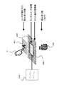
- FIG. 3 is a side sectional view of game device 10-1 according to the embodiment of the present invention. It is a schematic plan view of game device 10-1 according to an embodiment of the present invention.
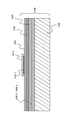
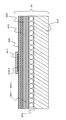
- FIG. 6 is a cross-sectional view of protective layer 610 and protective layer 611 of play field 60 of game device 10-1 according to the embodiment of the present invention.
- FIG. 6 is a conceptual diagram of the code
- It is a flowchart of the play processing of the game device 10-1 according to the embodiment of the present invention. It is a flowchart of the game processing of the game device 10-1 according to the embodiment of the present invention.
- FIG. 7 is a flowchart showing processing for detecting cards 80-1 to 80-n using ordinary paper media according to the embodiment of the present invention. It is a conceptual diagram which shows the relationship between the magnitude
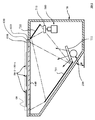
- FIG. 1 is a side sectional view of a game apparatus 10-1 having a configuration using a projector according to an embodiment of the present invention.
- FIG. 3 is a plan view of a play field of game device 10-1 having a configuration using a projector according to an embodiment of the present invention. It is sectional drawing of the play field 60 by the structure using the projector which concerns on embodiment of this invention.
- the game system X is a business video game machine (video game system) provided in a game facility such as a game center, a shopping store, or a sports facility.
- the game system X includes a plurality of game devices 10-1 to 10-n, a server 5, and a large display device 55.
- the game devices 10-1 to 10-n are connected to each other via a wired or wireless network, and a plurality of players can play a battle.
- the game system X may play a battle with other game apparatuses 10-1 to 10-n provided in other play facilities via the server 5 serving as a so-called “lobby” server. it can.
- the server 5 totals the score, sales, and remaining amount of cards to be paid out of the game devices 10-1 to 10-n. Further, the server 5 displays the game screens, rankings, operating statuses, and the like of the game devices 10-1 to 10-n on the large display device 55. Further, the server 5 can also be connected to a higher-level master server (not shown) to report the score ranking, sales, and the like.
- the server 5 can also download a program for the game devices 10-1 to 10-n, a firmware updater stored in the boot ROM 130, and the like from the master server, and update each device.
- the game apparatus 10-1 will be described as a representative example.
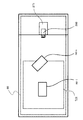
- game device 10-1 (game device) is similar to a conventional card game device, such as IC card reader / writer unit 220, card payout unit 230, switch 240, coin insertion unit 250, display 270, and the like. It has.
- a conventional card game device such as IC card reader / writer unit 220, card payout unit 230, switch 240, coin insertion unit 250, display 270, and the like. It has.
- the player P who is a user of the game apparatus 10-1 starts a game using the game apparatus 10-1 will be described.
- the player P sets up a set of cards such as a “starter pack” in which cards 80-1 to 80-n (playing media) used for playing a card game (playing media) and an IC card 85 are set. Purchase with a vending machine (not shown).
- the IC card 85 is used for storing data relating to the game.
- the cards 80-1 to 80-n are used for the player P to operate units, game characters, etc. in the actual game.
- a three-dimensional object such as a figure can be used as the game medium such as the cards 80-1 to 80-n.
- the player P when playing a game, the player P sets the IC card 85 in the IC card reader / writer unit 220. Then, the player P inserts coins into the coin insertion unit 250 or makes a settlement using a prepaid card or the like. Then, the player P places the cards 80-1 to 80-n on the play field 60 and moves them, or presses the switch 240 or the like to play the game. The progress of the game is displayed on the display 270. Further, it is displayed on the large display device 55 via the server 5. When the game is over, data relating to the game including the game results is written to the IC card 85.
- the card payout unit 230 outputs cards that can be used as the cards 80-1 to 80-n from the next time. At this time, the card payout unit 230 selects and outputs a card at random, for example.
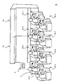
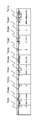
- the game device 10-1 includes a CPU 100 (control unit, game execution unit, area calculation unit), a storage unit 110, a boot ROM 130, a peripheral I / F 140 (peripheral device connection interface means), a bus arbiter 150, a graphic Processor 160 (drawing means), graphic memory 170, audio processor 180, audio memory 190, communication I / F 200, IC card reader / writer unit 220, card dispensing unit 230, switch 240, and coin insertion Unit 250, infrared camera 260 (first detection unit, image detection unit, imaging unit), display 270 (display unit), projector 275, speaker 280, and touch panel reading unit 300 (second detection unit, Contact detection unit).
- the CPU 100 includes a CISC (Complex Instruction Set Computer) system or a RISC (Reduce Instruction Set Computer) system CPU (Central Processing Unit), MPU (MicroDSP) (Digital Signal Processor), ASIC (Application Specific Processor), and the like.
- the CPU 100 is a control means having a calculation / control capability. Further, the CPU 100 can be provided with functions such as a storage unit 110, a graphic processor 160, and an audio processor 180 described later. Further, the CPU 100 uses the program 111 to acquire and correct the touched positions of the cards 80-1 to 80-n (FIG. 2), and the images of the codes 810-1 to 810-n (FIG. 11). Recognition can also be performed.
- the storage unit 110 includes high-speed storage means used for main storage such as RAM (Random Access Memory), HDD (Hard Disk Drive), flash memory, SRAM (Static Random Access Memory), magnetic tape device, optical disk device, and the like. Auxiliary storage means.
- the storage unit 110 includes a program 111 and data 112.
- the storage unit 110 includes an OS (Operating System, not shown) for causing the game apparatus 10-1 to function as a computer.
- the program 111 and the like can access each function of the game apparatus 10-1 through various APIs (Application Programming Interfaces) of the OS.
- the program 111 is a program for the CPU 100 to execute the card game of the game apparatus 10-1.
- the program 111 itself can be downloaded from the server 5 and updated, or downloaded at the start of the game.
- Data 112 is various data for the card game program 111.
- the data 112 includes data necessary for a card game, such as scenario data described later, data for each card, character display polygon data, music data, and the like.
- the data 112 can also store information such as difficulty level settings.
- the boot ROM 130 is a nonvolatile storage medium such as a ROM (Read Only Memory), a NOR flash memory, or an SRAM. Further, the boot ROM 130 sets the microcode of the CPU 100 when the game apparatus 10-1 is activated. The boot ROM 130 initializes each unit. In addition, the boot ROM 130 activates an OS or the like from the storage unit 110 and gives an instruction to execute the program 111.
- the boot ROM 130 includes a program and data for setting an IP address of the communication I / F 200, performing an operation test of each unit, and counting the number of coins and cards.
- the peripheral I / F 140 is a part that provides an interface such as USB, IEEE 1394, serial, parallel, infrared, and wireless for connecting to various peripheral devices (peripherals).
- an illumination unit 210 (light source unit, radiation unit), an IC card reader / writer unit 220, a card dispensing unit 230, a switch 240, A coin insertion unit 250 and an infrared camera 260 can be used.
- force feedback devices such as stick type controllers, acceleration detectors, vibration devices, foot / hand-operated switches, position detectors that detect the position on the screen of a display monitor, touchpad, touch panel, keyboard, mouse,
- a pointing device such as a trackball
- the peripheral I / F 140 can also control an electronic switch or the like. Accordingly, the peripheral I / F 140 can also suppress power consumption by turning on / off power of various peripheral devices.
- the bus arbiter 150 is an integrated circuit that provides a bus interface for connecting each part, such as a so-called “chip set”.
- the bus speed of each part connected by the bus arbiter 150 may be different, and may be asymmetric in up / down.
- the CPU 100, the storage unit 110, and the bus arbiter 150 are preferably connected by a high-speed bus such as FSB or HT.
- the graphic processor 160 and the bus arbiter 150 are connected by a broadband bus.
- the CPU 100 may include a bus interface such as a DDR2 / 3 SDRAM or an XDR DRAM so that the storage unit 110 can be directly read and written.
- the graphic processor 160 is a graphic processor having a function of drawing a three-dimensional CG.
- the graphic processor 160 includes a geometry unit 162 that calculates a polygon geometry (coordinates) and a rendering unit 164 that rasterizes / renders (draws) the polygon for which the geometry calculation has been performed.
- the graphic processor 160 includes a RAM DAC (RAM D / A converter) for outputting a rendered image to the display 270 and the projector 275, an HDMI interface, and the like. Further, the graphic processor 160 performs processing such as subtracting the image data of the play field sheet 620 (FIG. 8) previously captured from the infrared image data captured by the infrared camera 260 at high speed. As a result, the graphic processor 160 can remove noise from the image data and make the image data easy to perform image recognition.
- the graphic processor 160 can also perform image recognition itself of the codes 810-1 to 810-n (FIG. 11).
- the geometry unit 162 is a part for rotating and enlarging a matrix with respect to coordinates (world coordinates) of a polygon in a three-dimensional space. Further, the geometry unit 162 performs affine transformation or the like to obtain the coordinates of the polygon in the two-dimensional space.
- the geometry unit 162 can also include a “geometry shader” (or vertex shader) that performs tessellation such as polygon division and spline interpolation.
- the rendering unit 164 is a part that pastes image data called texture on the coordinate-calculated polygon and draws it in the graphic memory 170 with various effects.
- the polygons drawn by the rendering unit 164 include point polygons (points), line polygons (line lists), surface polygons such as triangles and quadrangles, and a collection of surface polygons.
- point polygons points
- line polygons line lists
- surface polygons such as triangles and quadrangles
- a collection of surface polygons when the rendering unit 164 performs rendering using ray tracing or the like, an object defined by a region such as a circle, an ellipse, a sphere, or a metaball can be rendered.
- the geometry unit 162 may be configured to be processed by the CPU 100. In this case, the CPU 100 executes a program stored in the storage unit 110 to create polygon coordinates. Then, the CPU 100 transfers the polygon coordinates to the graphic memory 170.
- the rendering unit 164 draws the polygon according to the polygon coordinates.
- the graphic memory 170 is a storage medium that can be read and written at high speed for the graphic processor 160 to draw.
- a broadband memory such as GDDR (Graphics Double Data Rate (graphics double data rate)
- this memory can be connected using high-level memory interleaving or the like.
- a configuration in which the graphic memory is built in the graphic processor 160 as in the system LSI is also possible. It is also possible to adopt a dual port configuration for displaying on a display monitor while the graphic processor 160 is drawing.
- the audio processor 180 is a DSP (digital signal processor) provided with a PCM (Wave) sound source for outputting music, voice, and sound effects.
- the audio processor 180 calculates a physical calculation sound source, an FM sound source, and the like.
- the audio processor 180 can also calculate various audio effects such as reverberation and reflection.
- the output of the audio processor 180 is D / A (digital / analog) converted and connected to a digital amplifier or the like. This output is reproduced by the speaker 280 as music, voice or sound effect.
- the audio processor 180 can also handle voice recognition of voice input from a microphone.
- the audio memory 190 is a storage medium that stores digitally converted data for music, voice, and sound effects. Of course, the audio processor 180 and the audio memory 190 can be integrally configured.
- the communication I / F 200 is an interface for connecting to a network such as a LAN (Local Area Network) or a WAN (Wide Area Network).
- the communication I / F 200 for example, WiMax (registered trademark), c. Link (registered trademark), HDMI (registered trademark), wired / wireless LAN, telephone line, mobile phone network, PHS network, power line network, IEEE 1394, etc. ) Can be used.
- WiMax registered trademark
- c. Link registered trademark
- HDMI registered trademark
- wired / wireless LAN telephone line
- mobile phone network PHS network
- power line network IEEE 1394, etc.
- the game apparatus 10-1 can communicate with other game apparatuses 10-2 to 10-n and the server 5.
- a battle game (a game that competes for a battle or the like; the same applies hereinafter) or a joint game (in cooperation with other players of the other game devices 10-2 to 10-n that are communicably connected).
- a game that solves the problem by connecting the plurality of game apparatuses 10-1 to 10-n so that they can communicate with each other, it is possible to collect game scores (scores, scores, etc., hereinafter referred to as scores) via the server 5.
- scores game scores
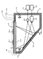
- the illumination unit 210 is a part that emits electromagnetic waves that are invisible to the naked eye and that is provided inside the housing 70 (see FIGS. 6 and 26) of the game apparatus 10-1.
- the illumination unit 210 is a part including an infrared lamp, an infrared LED array, an ultraviolet LED array, and the like, and a relay, an electronic switch, and the like (hereinafter described using an example of infrared rays).
- the illumination unit 210 may include a wavelength selection filter such as the first filter 711 in FIG. 6 in order to remove visible light components from the radiated infrared rays. Infrared rays are applied to the cards 80-1 to 80-n placed on the play field 60 in FIG.
- the illumination unit 210 also includes illumination for turning on an LED (not shown), a light, and the like outside the housing 70 and a switch for the illumination.
- the IC card reader / writer unit 220 is a known IC card reader or IC card writer for reading / writing information from / to the IC card 85 (FIG. 2).
- This IC card 85 stores personal results. Further, the IC card 85 stores the name, growth level, and the like of the character on the game associated with each of the cards 80-1 to 80-n. In addition, the IC card 85 can also write and store information on opponents to play, billing information, and the like.
- the IC card 85 includes a storage unit such as a non-volatile flash memory and a control unit such as an MPU.
- the IC card reader / writer unit 220 is activated by supplying power to the IC card 85 and writes it in the flash memory.
- the card payout unit 230 is a part for paying out (outputting) cards that can be used as the cards 80-1 to 80-n from the next time.
- information related to a game such as a unit or a game character is drawn on one side (for example, the front side).
- a code (such as codes 810-1 to 810-n in FIG. 11) using ink that reflects electromagnetic waves invisible to the naked eye such as infrared rays is printed.
- the card output by the card payout unit 230 can be replenished by the administrator of the game apparatus 10-1 by randomly arranging it in a keyed casing. This is the same as the coin insertion unit 250.
- the CPU 100 instructs the card payout unit 230 to pay out the card.
- the card dispensing unit 230 includes a printer using ink that reflects electromagnetic waves that are invisible to the naked eye such as infrared rays, and can print codes 810-1 to 810-n.
- the card payout unit 230 may print and output the encrypted issue date, issue location, ID (Identification), etc., on the codes 810-1 to 810-n when the card is output. it can.
- the number of cards to be paid out can be increased according to the game results.
- the type and number of cards to be paid out can be selected according to the game results (score, score, score, score, etc.).
- the switch 240 is a button, pad, joystick or the like.
- the switch 240 is used for various selections, menu calls, name inputs, and the like when playing a card game.
- the coin insertion unit 250 is a part (payment information detection unit) that detects a coin or a prepaid card that is inserted for a user to play a card game.
- the coin insertion unit 250 can transmit this signal when detecting a predetermined coin or amount.
- a predetermined coin or amount As this coin, an economic value medium such as an actual money or a medal used in an amusement facility can be used.
- the coin insertion unit 250 also includes a box for storing coins and the like. The administrator of game device 10-1 can access this box by opening case 70 (FIG. 6) using a key (not shown).
- the infrared camera 260 is a CCD camera or CMOS camera that can acquire image data by detecting electromagnetic waves that are invisible to the naked eye such as infrared rays (for example, light having a predetermined wavelength such as a wavelength of 0.7 to 2.5 ⁇ m). Imaging means (imaging unit). Moreover, in order to image only the electromagnetic waves (light) of a wavelength like infrared rays, you may provide the 2nd filter 712 of FIG. The infrared camera 260 captures infrared images reflected from the back of the cards 80-1 to 80-n placed in the play field 60 of FIG. 6 and creates image data.
- codes 810-1 to 810-n that are two-dimensional codes printed with invisible infrared reflective ink or the like on the back surfaces (back surfaces) of the cards 80-1 to 80-n.
- the CPU 100 and the graphic processor 160 can read the information described in the position and angle of each card and the code from the infrared image data captured by the infrared camera 260.
- the illumination unit 210 and the infrared camera 260 a configuration in which a code 810-1 to 810-n is read by incorporating an optical sensor in the liquid crystal element itself, such as “system liquid crystal”, is also possible.
- the display 270 is a display means (display unit) such as a liquid crystal display, a PDP (plasma display panel), or an HMD (head mounted display).
- the display 270 displays specific game developments, scores, and the like related to the arrangement of cards.
- the display 270 can also display a setting screen or the like.
- the projector 275 is a projection unit (projection unit) that projects a video (image).
- an optical projector such as a MEMS (Micro Electro Mechanical Systems), an LCOS (Liquid crystal on silicon), a transmissive high-temperature polysilicon LCD, or a laser can be used.
- the play field 60 (FIG. 2) includes a screen 635 (see FIG. 27) described later. Thereby, it is possible to use the projector 275 for the card game which projects an image.
- the speaker 280 is a part that amplifies the audio signal (audio information) output from the audio processor 180 with a digital amplifier or the like and outputs the audio.
- the speaker 280 may further include a microphone (not shown) for performing voice input.
- the touch panel reading unit 300 is a contact detection unit (contact detection unit) having a plurality of detection functions for detecting a plurality of touched points. That is, the touch panel reading unit 300 can detect a contact state when the touch panel reader 300 is touched.
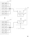
- the touch panel reading unit 300 can be configured to include touch electrodes 400-1 to 400-n and sensor microcomputers 310-1 to 310-n.
- the touch electrodes 400-1 to 400-n are formed so as to be substantially transparent, and are formed so as to substantially transmit invisible electromagnetic waves (light having a predetermined wavelength) such as infrared rays from the illumination unit 210.
- the touch electrodes 400-1 to 400-n are capacitive touch panel switches, resistive film type touch switches, and the like.
- the touch electrodes 400-1 to 400-n can form conductive divided regions (areas) on a transparent substrate such as a sheet by using a manufacturing method described later.
- the sensor microcomputers 310-1 to 310-n are microcomputers (MPUs, sensor control units) or the like that acquire capacitance from the touch electrodes 400-1 to 400-n and detect contact.
- the touch panel reading unit 300 includes, for example, touch electrodes 400-1 to 400-n formed by printing and sensor microcomputers 310-1 to 310-n. It is configured. Each of the touch electrodes 400-1 to 400-n includes a plurality of electrodes serving as a plurality of touch sensors. Each of the sensor microcomputers 310-1 to 310-n is connected to a corresponding electrode 401-1 to 401-n. Each of the sensor microcomputers 310-1 to 310-n scans each electrode according to an instruction from the CPU 100. In this scan, the sensor microcomputers 310-1 to 310-n obtain A capacitance value by A / D converting the capacitance of each electrode.
- the scanned capacitance value can be read out by the control means (control unit) such as the CPU 100 or the graphic processor 160 via the peripheral I / F.
- the control means detects which of the electrodes 401-1 to 401-n has changed the capacitance value upon reading. Thereby, a plurality of pieces of information such as coordinates touched on the play field 60 (FIG. 6) and the housing 70 (FIG. 6) can be detected simultaneously.
- the sensor microcomputers 310-1 to 310-n may be grouped as a sensor microcomputer array 301 on a chip-on-chip basis.
- a card touch sensor and a code reader can be combined. .
- the code of the card 80-1 can be read from the back side using a reader such as a camera.
- the print target of a game medium such as the card 80-1 may be a card or a three-dimensional object.
- the effect that touch detection and code reading can be made compatible is acquired.
- the type of detection target for example, a card
- there are some that affect the capacitance there are some that affect the capacitance. In view of this, it is possible to cope with this influence by detecting the type of the detection target with the code recognized from the infrared image and correcting the capacitance value.
- a play field 60 (a plane, a plane portion) is configured on the upper portion of the housing 70.
- the play field 60 includes, for example, a protective layer 610, a play field sheet 620, a touch panel sheet 630, and a glass plate 640.
- Each part is almost transparent to infrared rays.
- each is made up of members that are substantially transparent to infrared.
- the cards 80-1 to 80-n are disposed on the protective layer 610.
- the infrared rays are transmitted through the first filter 711 that transmits almost only infrared rays.
- the infrared rays hit the surface on which the codes of the cards 80-1 to 80-n (for example, the codes 810-1 to 810-n in FIG. 11) are drawn.
- the infrared rays reflected from the cards 80-1 to 80-n are narrowed down through the first reflecting plate 721 and the second reflecting plate 722.
- the narrowed infrared ray passes through the second filter 712 that allows only the infrared ray to pass therethrough.
- the infrared camera 260 can image this infrared ray.
- the touch electrodes 400-1 to 400-n (see FIGS. 8 and 9) printed on the touch panel sheet 630 make contact with the cards 80-1 to 80-n. Can be sensed.
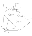
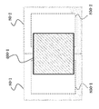
- FIG. 7 a schematic diagram of a plane drawn from the direction (upper surface) in which the user looks down in the vicinity of the play field 60 of the game apparatus 10-1 will be described.
- cards 80-1 to 80-n are arranged in the play field 60.
- the illumination unit 210, the first filter 711, the first reflector 721, the second reflector 722, the second filter 712, and the infrared camera 260 are arranged in a line.
- the display 270 can be installed above the second reflection plate 722 and on the housing 70.
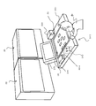
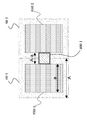
- FIG. 8 is a schematic diagram of the play field 60.
- cards 80-1 to 80-n are arranged on play field 60.
- the first filter 711 mainly the infrared light of the light source of the illumination unit 210 is irradiated on the back surface of the play field 60.
- the touch panel sheet 630 and the play field sheet 620 substantially transmit infrared light.
- infrared light is applied to the back of the cards 80-1 to 80-n.
- the code can be recognized by reading the infrared light reflected from the back of the cards 80-1 to 80-n.
- the game apparatus 10-1 can recognize the coordinates of the user's finger on the play field 60.
- a glass plate 640 is provided from below (backward) where infrared light is irradiated.
- the glass plate 640 is glass or the like that is transparent to invisible light such as infrared rays.
- a touch panel sheet 630 is provided above the glass plate 640.
- each of the touch electrodes 400-1 to 400-n is (i) a method in which a conductive paste containing extremely fine conductive particles is screen-printed on a transparent substrate (Japanese Patent Application Laid-Open No. 2007-142334, etc.
- a printing method such as gravure printing, or (ii) a method in which a metal foil such as copper is laminated on a transparent substrate, a resist pattern is formed on the metal foil, and the metal foil is etched (Japanese Patent Laid-Open No. 2008-2009). And the like, and a manufacturing method such as photolithography.
- the conductive pattern corresponding to each electrode of the touch panel sheet 630 is connected to sensor microcomputers 310-1 to 310-n (not shown).
- a play field sheet 620 is provided above the touch panel sheet 630.
- the play field sheet 620 transmits infrared light although a schematic diagram of the field is printed, as in the prior art.
- a transparent protective layer 610 is provided above the touch panel sheet 630.
- Cards 80-1 to 80-n are arranged above the protective layer 610 by the user during the card game play.
- the card 80-1 is arranged is shown.
- a code 810-1 is printed on the back surface of the card 80-1.
- the code 810-1 can be optically read by reflected infrared rays or the like.
- the touch panel sheet 630 may be positioned above the play field sheet 620. Further, the play field sheet 620 or the touch panel sheet 630 may be formed integrally with the protective layer 610. Further, when a projector or the like is used as described later, another layer for projecting video (image) may be provided.
- the protective layer 610 can include a conical protrusion as shown in FIG. Further, as shown in FIG. 10B, hemispherical protrusions can be provided. Such protrusions reduce friction. Therefore, the cards 80-1 to 80-1 to 80-n can be smoothly moved and played. Further, wear of the protective layer 610 can be suppressed. Further, since infrared light is diffused by the protrusions, erroneous recognition of the codes 810-1 to 810-n due to scratches on the protective layer 610 can be reduced. Referring to FIG. 10 (a), the end portion 611 of the cone is formed flat rather than as a complete protrusion.
- the diameters of the conical trunk portion 612 and the end portion 611 can be formed such that moire patterns are not easily generated when the codes 810-1 to 810-n are recognized.
- the hemispherical portion 613 in FIG. 10B By forming the hemispherical portion 613 in FIG. 10B to be hemispherical, it is possible to further reduce irritation to the user's hand. Moreover, the effect that it is easy to remove dirt at the time of wiping off is also acquired.
- the diameter of the hemisphere can also be formed so as not to cause a moire pattern.
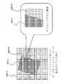
- the cord 810-1 has a structure in which several circumferential bands extend from the central axis 820.
- the code 810-1 can distinguish between a place where the brightness of infrared reflection is high (white) and a place where the brightness is low (black). Various information can be described by this black and white pattern.
- the code 810-1 is arranged in a circle, so that the position (coordinates) and orientation (angle) of the card on the play field 60, and the boundary between the card and other locations can be accurately recognized. Can be grasped. As a result, the touch panel and the code can be read simultaneously.
- the position pressed (contacted) can be accurately grasped.
- the manufacturing cost of the touch electrodes 400-1 to 400-n and the cost of the arithmetic device for recognition can be suppressed.
- the black and white pattern of the code 810-1 for example, information can be described using a gray code. Thereby, the influence at the time of misrecognition can also be suppressed.
- the code 810-1 is not limited to a black and white pattern, and for example, information can be described using coordinate information based on a predetermined pattern or a dot pattern meaning a code. Thereby, it is also possible to increase the amount of information to the game medium.
- the pattern can have a plurality of values depending on the reflection frequency of invisible light such as infrared rays.
- the card type includes information on a special “kira card” described later.
- the information described in the code 810-1 includes information as to which position of the card is touched and whether or not a “special attack” or the like as described later can be performed.
- the information described in the code 810-1 includes an ID for distinguishing the same type of card by a serial number or the like.
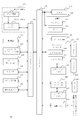
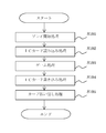
- FIG. 12 Player processing of game device 10-1
- a player P who is a user of the game apparatus 10-1 in FIG. 2 specifically uses the game apparatus 10-1 to play a card game.
- a control unit such as the CPU 100 mainly executes a specific process using hardware resources such as the program 111 and data 112 stored in the storage unit 110.
- Step S101 the CPU 100 performs a play start process.
- the CPU 100 detects whether the IC card 85 is inserted using the IC card reader / writer unit 220 via the peripheral I / F 140.
- the CPU 100 uses the coin insertion unit 250 via the peripheral I / F 140 to detect that a payment has been made by inserting a coin or using a prepaid card.
- the process proceeds to step S103.
- the CPU 100 displays a screen for instructing insertion of coins or a prepaid card on the display 270 or outputs audio from the audio processor 180 to the speaker 280.
- the CPU 100 When payment is made without the IC card 85 being inserted, the CPU 100 prompts the user to insert the IC card 85 and notifies that the starter pack of the IC card 85 needs to be purchased. In a state where the IC card 85 is not inserted and payment is not performed, the CPU 100 can display a demonstration screen on the display 270 to attract the interest of the player. At this time, the CPU 100 can make the player know that the game apparatus 10-1 is not being played by not outputting sound.
- Step S102 the CPU 100 performs an IC card reading process.
- the CPU 100 reads the data of the IC card 85 using the IC card reader / writer unit 220 via the peripheral I / F 140.
- the IC card 85 is a contact type or non-contact type IC card.
- the IC card 85 includes a flash memory (storage unit), an MPU (control unit), and the like, and can encrypt and store data relating to the game.
- data relating to this game as will be described later, data such as the level of each character of each card 80-1 to 80-n, military funds in the game, territories controlled, ranking, etc. can be stored. .
- the play level of the player P and the like are also stored.
- game-related information, player-related information, and the like can be stored.
- the game-related information relates to a game such as a scenario number in progress in the “campaign mode”, the number of territories in control, and whether the play of the player P has cleared a plurality of game scenarios.
- the player-related information relates to the player such as how many pieces of powerful ability value data are possessed among the cards 80-1 to 80-n and the winning percentage of play in the card game.
- the CPU 100 can change selectable scenarios according to the level of play.
- the CPU 100 can end the play process without proceeding to the next step S103. .
- the CPU 100 transmits data of “IC card failure / illegal” to the server 5.
- the CPU 100 can instruct the speaker 280 to sound a siren or the like from the audio processor 180 and prompt a call to a clerk (staff) of the amusement facility.
- the CPU 100 can also pay back coins from the coin insertion unit 250.
- Step S103 the CPU 100 performs a game process that specifically executes the game.
- the CPU 100 executes a part of the program 111 in the storage unit 110 that performs a specific game process.
- a game device 10-1 according to an embodiment of the present invention executes a tactical class real-time simulation game (real-time strategy) that deals with battles of the Sangokushi-style era.
- the flow of this real-time simulation game is as follows. First, the CPU 100 reads out a game scenario according to the user's selection of a game mode or the like.
- the CPU 100 gives an instruction using AI (artificial intelligence), or the opponent gives an instruction via the network.
- AI artificial intelligence
- the player P places cards 80-1 to 80-n, selects (contacts) the cards 80-1 to 80-n, and switches 240
- An instruction is given by selecting a command or the like. Instructions to these enemy units, neutral units, and friendly units are calculated by the CPU 100 in units of “frames” every 1/60 seconds, for example, and reflected in the progress of the game in real time.
- the CPU 100 increases or decreases the personnel of the unit, or causes a change that the position on the map belongs to a friendly unit or an enemy unit. Further, the CPU 100 causes the graphic processor 160 to draw this change on the display 270. Further, the CPU 100 uses the audio processor 180 to output sound effects and BGM (background music) from the speaker 280.
- the CPU 100 ends the game process when a scenario ending condition such as a unit personnel, arrangement, or position affiliation is satisfied or a predetermined time elapses.
- the game system X is a so-called multi-platform. That is, the game apparatus 10-1 can select and play a plurality of types of games. At this time, it is possible to describe the types of games that can be played on the IC card 85 and to download and execute the program 111 itself from the server 5 in accordance with the selection of the player P. Further, when the player P is playing a game, the play content can be displayed on the large display device 55 via the server 5 of FIG. 1 to enjoy a more powerful play.
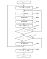
- the game process will be described in detail with reference to FIG.
- Step S301 First, the CPU 100 performs a scenario reading process.
- the player P in FIG. 2 selects a game mode.
- the buttons and switches 240 of the software keyboard drawn in the play field 60 are used.
- a mode such as “campaign mode”, “national conquest mode”, “matching mode”, “scenario selection mode”, “tutorial”, etc. can be selected.
- “Campaign mode” wins the prepared scenarios in order.
- “Nationwide conquest mode” selects a scenario for each country by selecting the “country” to attack.
- a scenario is selected between the player P and the other game apparatuses 10-2 to 10-n to play a battle.
- scenario selection mode a scenario that has finished (cleared) a scenario can be selected.
- “Tutorial” teaches how to play the game for beginners.
- the CPU 100 reads a scenario corresponding to each game mode in accordance with the instruction of the player P.
- This scenario may be stored as a part of the data 112 in the HDD of the storage unit 110 or the like. Further, the scenario may be configured to be downloaded from the server 5.
- map data As the contents of the scenario data, map data, unit placement data, end condition data, special weapon data, and the like can be used.
- the map data is 3D data (virtual three-dimensional space information) of a map that becomes a battlefield.
- the map data is subjected to projection conversion, viewpoint change, shading (shaded) processing and the like in real time using the graphic processor 160, and is displayed on the large display device 55 from the server 5 via the display 270 or the network.
- the map data includes data such as height and terrain attributes. In the data such as the height and the terrain attribute, it is possible to specify terrain data such as swamps and pits related to the advancing speed of the unit and steep slopes where the unit cannot proceed. Further, the “location” data is stored on the map data.
- Enemy units and friendly units move to the coordinates and take the “flag” to control the “base”.
- objects such as castles, stone walls and moats can be arranged at each base.
- the unit arrangement data can be stored by determining the arrangement of enemy units and allies on the map data, the timing of reinforcement, the scenario end condition, and the like.
- the end condition data can be stored by setting the annihilation of the enemy unit or the friendly unit as a condition.
- various conditions can be determined and stored, for example, when a predetermined position is controlled, when a leader of a specific unit is defeated, or when a predetermined “deadly move” is activated.
- the CPU 100 starts a process related to a specific game play.
- Step S302 The CPU 100 performs card detection processing for detecting the arrangement and contact state of the cards 80-1 to 80-n. As described above, this process is to detect an instruction for the player P in FIG.
- game device 10-1 according to the embodiment of the present invention uses the arrangement state and contact state of cards 80-1 to 80-n. Using the state of placement and the state of contact is not a mere combination. Thereby, unlike the prior art, various instructions that can improve game performance can be detected. First, in the following, with reference to FIGS. 14 to 20, a detailed description will be given of how to detect the code and specify the touch position for each of the cards 80-1 to 80-n.
- the code When detecting the code, the code is detected by reading the codes 810-1 to 810-n using infrared rays or the like. When the touch position is specified, the touch position is specified by touching the touch electrodes 400-1 to 400-n.
- this card detection process (1) a process for detecting cards 80-1 to 80-n using ordinary paper media, and (2) a special “kira card” (capacitance that is contained in metal foil or the like) The description will be divided into processing for detecting cards 80-1 to 80-n including game media having different values. Which process (1) or (2) is selected can be selected according to the type of card game.
- the CPU 100 stores and selects in the nonvolatile memory of the storage unit 110.
- the touch electrodes 400-1 to 400-n are capacitance electrodes formed on the touch panel sheet 630 by printing or the like (see FIGS. 4 and 8).
- the touch electrodes 400-1 to 400-n are connected to the sensor microcomputers 310-1 to 310-n by wiring. Therefore, “multi-touch”, that is, a plurality of pieces of information touching each electrode can be acquired at the same time. Further, by processing and using the image acquired by the infrared camera 260, it is possible to detect the position of the card and the contact position with higher accuracy.
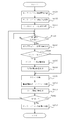
- Step S1021 the CPU 100 of the game apparatus 10-1 performs sensor microcomputer operation start processing.
- the CPU 100 controls the electronic switch from the peripheral I / F 140.
- the CPU 100 supplies power to the sensor microcomputers 310-1 to 310-n.
- the sensor microcomputers 310-1 to 310-n can be operated only during the game process. Therefore, an effect that the operating cost of the game apparatus 10-1 can be reduced is obtained.
- Step S1022 the CPU 100 performs a sensor microcomputer communication connection process.
- the CPU 100 checks whether communication connection is possible between the sensor microcomputers 310-1 to 310-n and the CPU 100 via the peripheral I / F 140. If any of the sensor microcomputers 310-1 to 310-n does not respond as a result of this check, it is assumed that a failure has occurred. At this time, the CPU 100 transmits to the server 5 via the communication I / F 200. Also, a siren or the like is sounded to notify the administrator of the game apparatus 10-1. If all the sensor microcomputers 310-1 to 310-n have responded, the CPU 100 advances the process to step S1023.
- Step S1023 the CPU 100 performs sensor microcomputer initialization processing.
- an initial signal or the like is transmitted to the sensor microcomputers 310-1 to 310-n.
- each of the sensor microcomputers 310-1 to 310-n starts the initialization process from the initial position of the built-in ROM or the like.
- the sensor microcomputers 310-1 to 310-n perform processing such as connection confirmation and calibration for the connected touch electrodes 400-1 to 400-n.
- each of the sensor microcomputers 310-1 to 310-n transmits log data as a result of the initialization process to the CPU 100.
- the CPU 100 can notify the administrator of the game apparatus 10-1 by transmitting it to the server 5 via the communication I / F 200 and sounding a siren or the like. Thereafter, when the initialization process is normal, each of the sensor microcomputers 310-1 to 310-n waits for a detection start signal from the CPU 100. In the following, detection of card contact after the card game is started will be described using the sensor microcomputer 310-1 as a representative example of the sensor microcomputers 310-1 to 310-n.
- Step S1024 the sensor microcomputer 310-1 determines whether a detection start signal is received from the CPU 100. This detection start signal is transmitted by the CPU 100 after the card game is started. With this detection start signal, as described above, the sensor microcomputers 310-1 to 310-n can detect contact of the cards 80-1 to 80-n at about 60 times / second. If the determination in step S1024 is Yes, the sensor microcomputer 310-1 advances the process to step S1030. Conversely, if the determination in step S1024 is No, the sensor microcomputer 310-1 returns the process to step S1024.
- Step S1025) the sensor microcomputer 310-1 performs a scanning process. Specifically, the capacitance is sequentially measured from each electrode of the touch electrode 400-1 scanned by the sensor microcomputer 310-1, and subjected to A / D conversion or the like to obtain a capacitance value (touch count value). Get. With this capacitance value, a value as to whether each electrode is turned on / off can be obtained. Moreover, the value about the touch contact pressure (contact area) can be obtained.
- the sensor microcomputer 310-1 writes the capacitance values in the storage unit 110 by DMA transfer or the like via the communication I / F 200. Further, the CPU 100 can directly acquire the capacitance value and store it in the storage unit 110. Thereby, the scanning process is terminated.
- Step S1026 the CPU 100 performs an electrode coordinate acquisition process.
- the CPU 100 acquires the coordinates of the electrode touched (pressed) by the user from the capacitance values acquired from the sensor microcomputers 310-1 to 310-n.
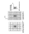
- the relationship between the size of each electrode and the coordinate acquisition of the pressed (contacted) electrode will be described in detail with reference to FIGS.
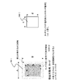
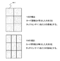
- the inventor of the present invention repeated diligent experiments and research to use it specifically in games. Then, if there is an area of an effective area of about 70% with respect to the area of the card 80-1 that is an assumed detection target, the position of the card 80-1 can be accurately determined at high speed together with the subsequent recognition of the infrared image. I found that I can identify it. That is, the size of one electrode of the touch electrode 400-1 can be about 70% of the size of the card 80-1. Even when a figure or the like is used as a game medium instead of the card 80-1, for example, the area of the effective area such as 70% with respect to the area of the grounding surface on which an optical code such as a two-dimensional code is printed. Can be used.
- the size of one electrode is set using an effective area sufficient to detect each of cards 80-1 to 80-n from detection target card 80-1.
- a region per location of the touch electrode 400-1 is defined as length c ⁇ length d.
- a method of obtaining the length c and the length d will be described with reference to FIGS. 17A and 17B.
- a positional relationship in which the sensor just straddles adjacent cards that are in close contact with each other is a “worst condition” in which it is difficult to detect the position of contact. That is, when determining whether the electrode is “ON” from the capacitance value of the touch electrode 400-1, it is not possible to determine which of the card 80-1 and the card 80-2 is in contact. For this reason, in order to specify the card being touched, the size per electrode needs to be within the range of the “dead zone” that is an area outside the effective area.
- the area of the touch sensor can be set to a size in which the shorter one of the horizontal width c and the vertical width d is a diagonal line.
- the inventor of the present invention has conducted intensive experiments and researches.
- the electrodes of the touch electrodes 400-1 to 400-n are arranged with the maximum cost performance, 70 in the area to be detected.
- the effective region is about%. That is, touch electrodes (switches) can be provided to the minimum necessary for one of the cards 80-1 to 80-n. Therefore, when the effective area is set to 70% in this way, it is possible to detect the contact coordinates of the cards 80-1 to 80-n at a reduced cost.
- the sizes of the touch electrodes 400-1 to 400-n can be obtained based on an area obtained by equally dividing the area of the card 80-1 to be detected.
- an area of 1/6 or 1/9 of the cards 80-1 to 80-n is the equally divided area.
- the size obtained by dividing the card area into 6 equal parts is the size of one electrode of the electrode 400-1.
- the size obtained by dividing the card area into nine equals is the size of one electrode of the electrode 400-1.
- each of the touch electrodes 400-1 to 400-n it is preferable to arrange the electrodes so as to cover 70% of the cards 80-1 to 80-n.
- the contact position of each card 80-1 to 80-n is detected in detail so that the area is 1/6 or 1/9 of the area of the card 80-1 to 80-n. It is.
- Step S1027) Here, with reference to FIG. 14 again, (1) processing for detecting the cards 80-1 to 80-n using ordinary paper media will be described.
- the CPU 100 performs infrared image card position acquisition processing.
- the infrared camera 260 receives images printed on the back surfaces of the cards 80-1 to 80-n using infrared rays as shown in FIG.
- the CPU 100 analyzes the received image using the graphic processor 160 and the like, and recognizes codes 810-1 to 810-n as shown in FIG. As a result, it is possible to obtain operation information values for the coordinates (position), angle (direction), ID (card type), etc. on the play field 60 of the cards 80-1 to 80-n.
- the CPU 100 stores operation information values such as coordinates, angles, and IDs of the respective cards 80-1 to 80-n in the storage unit 110.
- operation information values such as coordinates, angles, and IDs of the respective cards 80-1 to 80-n in the storage unit 110.
- Step S1028) the CPU 100 performs card information acquisition processing.
- this card information -Position where the user touches on the play field 60 (contact information)
- -Acquire information such as the number of cards 80-1 to 80-n on the play field 60, ID, coordinates, angle, and touch information.
- the CPU 100 acquires information regarding that the cards 80-1 to 80-n on the play field 60 are touched, that is, touched, as touch information.
- touch information it is possible to use information such as a flag indicating whether the card is touched, the strength being touched, and the coordinates being touched.
- the touched coordinates are corrected based on the card image processing. Specifically, the correction is made based on the coordinates and angles of the cards 80-1 to 80-n and the coordinates of the contacted electrodes. As described above, the coordinates and angles of the cards 80-1 to 80-n are acquired by the infrared image card position acquisition process.
- the coordinates of the contacted electrode are acquired by the electrode coordinate acquisition process described above.
- the CPU 100 sets the position in the card as the contacted coordinates.
- the CPU 100 determines that the card 80-1 to 80-n is in contact with the contacted coordinates. To do.
- the capacitance value of the contact of the two to four electrodes indicates a close value, the CPU 100 is contacted with the coordinates of the electrodes closer to the cards 80-1 to 80-n. Coordinates. Also, temporal correction is possible.
- the touched coordinates can be updated in 1/60 seconds, for example. Therefore, when the electrode to be contacted moves, the CPU 100 selects which card 80-1 to 80-n has been contacted based on the amount of movement. Then, the CPU 100 sets the coordinates of the selected cards 80-1 to 80-n as touched coordinates. As described above, when the cards 80-1 to 80-n are in contact with each other, the CPU 100 can store the corrected coordinates in the touch information. In addition, the touched information in the card can also be stored in the touch information.
- Step S1029 the description returns to the operation of the sensor microcomputer 310-1.
- the sensor microcomputer 310-1 determines whether the detection of the contact with the card has been completed. Specifically, the sensor microcomputer 310-1 determines whether a detection end signal has been received from the CPU 100. Note that the CPU 100 can transmit this detection end signal at the end of the game process in step S103 of FIG. If the determination in step S1029 is YES, the sensor microcomputer 310-1 advances the process to step S1030. Conversely, if the determination in step S1029 is No, the sensor microcomputer 310-1 returns the process to step S1024, and repeats the process below the scan process, for example, every 1/60 seconds.
- Step S1030 When the detection ends, the CPU 100 performs a sensor microcomputer operation stop process. Specifically, when the sensor microcomputer 310-1 receives the detection end signal, the sensor microcomputer 310-1 enters a mode in which the operation is stopped to reduce power consumption, such as a HALT state. In addition, the CPU 100 controls the electronic switch from the peripheral I / F 140 to turn off the sensor microcomputers 310-1 to 310-n. Thereby, power consumption can be suppressed while the game is not being played, and malfunctions can be reduced. Thus, (1) the processing for detecting the cards 80-1 to 80-n using ordinary paper media is completed.
- a “kira card” is a card in which metal foil or the like is scattered like “lame” on the surface or inside, or foil printing such as an aluminum layer is performed. “Kira Card” is often used as a special valuable card in card games. In other words, this “kira card” has a low resistance due to the use of metal foil. When the “kira card” bridges between the electrodes straddling, it is detected including the capacitance between both electrodes, and as a result, the detected capacitance increases.
- step S1031 performs the same process as step S1021
- step S1032 performs step S1022
- step S1033 performs step S1023
- step S1034 performs the same process as step S1024.
- Step S1035) the CPU 100 performs infrared image card position acquisition processing. This process is also the same as step S1027 in FIG. As a result, the CPU 100 first determines the coordinates (position), angle (orientation), ID (card type), etc. on the play field 60 of the codes 810-1 to 810-n on the back of the cards 80-1 to 80-n. Get the value of. And CPU100 can determine whether it is a killer card by ID by subsequent processing, and can perform a correction process.
- Step S1036 the CPU 100 determines whether there is a glitter card. Here, it is determined whether or not there is a glitter card among the cards 80-1 to 80-n on the play field 60 of FIG. If the determination in step S1036 is Yes, the CPU 100 advances the process to step S1037. Conversely, if the determination in step S1036 is No, the CPU 100 advances the process to step S1039 and performs normal scan processing.
- Step S1037) The CPU 100 performs a kill card area calculation process. This will be described with reference to the conceptual diagram of FIG.
- each of the touch electrodes 400-1 to 400-n has a large capacitance value by a value proportional to the area where the glitter card and the electrode overlap.
- the touch switch calculates the sensitivity value from the relationship of the capacitance with the object on the electrode, the sensitivity value proportional to the area covering the electrode changes when the killer card is placed.
- game device 10-1 identifies the card position by recognizing codes 810-1 to 810-n. That is, the game device 10-1 recognizes the codes 810-1 to 810-n by image recognition, so that the specified position coordinates of the card can be used. Thereby, it is possible to calculate the area covering each electrode by combining the position coordinate information and electrode position information of the specified card. In other words, by using the calculated area and subtracting the increment of the sensitivity value in advance to perform the touch calculation, malfunctions of the electrodes 400-1 to 400-n can be suppressed.
- the overlapping area is calculated for each electrode overlapping the card 80-3. Since the position of the electrode is known in the play field 60, the known coordinate is stored in the storage unit 110, and the intersection of the card and the electrode is calculated to calculate the area of the overlapped portion. Can do. For example, in the example of FIG. 20, since the electrodes of the touch electrode 400-1 do not overlap, calculation is not performed. In contrast, since the electrodes of the touch electrode 400-9 are overlapped, the area of the overlapped portion can be calculated.
- Step S1038) the CPU 100 performs an electrode sensitivity value correction process.
- the “offset value” of the capacitance value of each electrode is calculated from the area of the overlapping portion of each electrode obtained in the above-described Kira card area calculation process.
- the coefficient can be stored in the storage unit 110 as a predetermined constant by previously obtaining the relationship between the capacitance and area of a normal card and a Kira card.
- the CPU 100 also stores the obtained offset value of each electrode as an array variable or the like corresponding to each electrode.
- step S1039 processing similar to that in step S1025 is performed, and each of the sensor microcomputers 310-1 to 310-n performs scanning processing.
- Step S1040 the CPU 100 performs electrode coordinate acquisition / offset processing.
- the CPU 100 performs an electrode coordinate acquisition process similar to step S1026. That is, the CPU 100 reads out the capacitance values acquired from the respective sensor microcomputers 310-1 to 310-n from the storage unit 110. Then, the CPU 100 reads out the offset value of each electrode described above from the storage unit 110 and performs a process of adding or subtracting it to the capacitance value corresponding to each electrode. As a result, it is possible to cancel the malfunction due to the glitter card and to accurately detect the contact of the cards 80-1 to 80-n. Thereafter, the CPU 100 erases the array of offset values of each electrode by performing zero fill or the like.
- Step S1041 performs the same processing as Step S1028, Step S1042 performs Step S1029, and Step S1043 performs Step S1030.
- Step S1041 performs the same processing as Step S1028, Step S1042 performs Step S1029, and Step S1043 performs Step S1030.
- the touch position acquisition by each of the sensor microcomputers 310-1 to 310-n and the processing of the image acquired by the infrared camera 260 are used, it is possible to detect the position touched by the user in the play field 60.
- the resolution can be set to, for example, 400 points or more over the entire play field 60.
- each of the cards for play 80-1 to 80-n has a size of about 86 mm ⁇ 54 mm, it is possible to obtain a resolution that can be divided into six without requiring much cost. It is also possible to have a resolution for obtaining points that can be divided into nine.
- game device 10-1 it is possible to detect a contact position of 60 points / second or more for 400 points in play field 60.
- This is a sufficiently high speed as compared with the conventional technique for optically detecting only the code. That is, when the user touches the cards 80-1 to 80-n, the contact position can be detected at a very high speed almost in real time.
- the drawing speed of a moving image that can be perceived by the human eye is about 60 frames / second. Further, the 60 frames / second is also a drawing speed generally used in games. Therefore, the drawing speed, the code detection speed, and the contact position detection speed can be matched.
- the reaction of the game apparatus 10-1 is delayed (heavy) than the instruction of the player P in the game.
- the game situation greatly depends on the speed of instructions for the placement of each unit. For this reason, the reaction speed is very important in the fun and operability of the game. Therefore, by providing a sufficient detection speed as in the card detection method according to the embodiment of the present invention, a great effect of improving the operability of the card game can be obtained.
- Step S303 Here, referring again to FIG. 13, the specific processing of the card game after card detection will be described in detail.
- the CPU 100 performs a teammate process. In this ally unit process, the CPU 100 obtains various instructions regarding the arrangement of the cards 80-1 to 80-n of the player P in FIG.
- the CPu 100 performs a process for causing each character in the team to act. As this action, move to the destination or battle with enemy units.
- the enemy unit is operated by the CPU 100 and other players. The results of these processes are reflected by the drawing process after the next enemy unit process.
- the friendly unit process in step S302 will be described in more detail.
- each unit has data of a unit such as a friendly unit, an enemy unit, and a neutral unit, and the game progresses according to the state of the unit.
- FIG. 22 shows an example of data elements related to a teammate.
- elements of this data elements such as a unit number D101, a leader number D102, a command D103, a special attack level D104, a target D105, a morale D106, and a member D107 can be provided.
- the unit number D101 is a part (unit number storage unit) that stores a number used on the program corresponding to each unit.
- the leader number D102 is a part for storing a number indicating the character of the military commander of the cards 80-1 to 80-n associated with the unit number (a military command storage unit).
- the command D103 is a part (behavior information storage unit) that stores data of a command of a unit action determined by the unit action instruction process.
- the special attack level D104 is a part (special attack level storage unit) that stores a “special attack level” used for a special attack described later.
- the target D105 is coordinates on the map or a part (coordinate information storage unit) indicating a unit to be pursued. This target D105 can be determined by the arrangement of the corresponding cards 80-1 to 80-n.
- the morale D106 is a part (morale parameter storage unit) that stores parameters related to morale. Morale is a value related to the strength of a unit's battle, ease of turning over, ease of attack, and the like.
- the member D107 is a part (member character storage unit) that stores a list of member characters. This member is variable except for the leader. Therefore, for example, an operation of joining units and distributing them with other units is possible. Further, it is possible to perform operations such as acquiring and increasing the number of characters laid down from enemy units. It is also possible to operate different characters such as archers and cavalry as the same unit. It should be noted that data such as the number of morale D106 and member D107 and the type of character can be stored in the IC card 85.
- Data elements related to each character may include elements such as member number D201, name D202, HPD 203, LVD 204, occupation D205, skill D206, gender D207, ability value D208, leader D209, item / equipment D210, and the like.
- the member number D201 is a number associated with each member character. This number can be added by the CPU 100 according to the program every time the card game is played.
- the name D202 is an element indicating the name of the character. This name is set to a default name in the case of a leader character. Also, the player P in FIG. 2 can give a name. Such a leader character name can be stored in the IC card 85.
- the name of the character other than the leader can be set from a predetermined name list by the CPU 100 using a program every time the card game is played.
- the HPD 203 is an element indicating the physical strength value of the character. When HP reaches 0, the character dies. The HP value can be restored to the user's support or automatically when in a particular location, such as a castle or other position on the map. Also, when the leader's HP becomes 0, the leader cannot be used as “uncombatable” while the game is being played. During recovery, a parameter on the card game called “Hyogi” decreases.
- the LVD 204 is an element indicating a level such as character strength. The level of the leader increases depending on the number of times played and the number of special attacks.
- the occupation D205 is an element indicating “occupation” related to the appearance, skill, etc. of the character on the polygon drawing.
- leaders such as military commanders, soldiers, and ninjas.
- special categories such as “future person”, “makaijin”, and “android” may be prepared for the above-mentioned Kira card.
- the occupation for leaders can have occupational attributes such as Daimyo, territory, villager, first leader, monarcher chief, and Shinobu.
- the occupations of characters other than the leader in the same unit can be used mainly for the characters constituting the unit, such as cavalry, archer, mercenary, and foot.
- This profession can be set according to the ratio when distributing the forces that can be moved on the scenario by the user to each unit after the scenario reading process.
- the occupation ratio of the soldiers of the unit can be stored in the IC card 85 for each leader. And according to the progress of the card game, you can also set the occupation of soldiers at this rate.
- the skill D206 is an attribute possessed only by the leader and stores a special attack method to be executed at the time of a special attack.
- This skill D206 can be increased with the value of the level D204 of the leader character. You can also “learn” the skills of enemy leaders.
- the sex D207 is a value related to the sex such as male, female, and neutral, and the character of the character. Depending on this gender and personality, values such as the ability to execute instructions by the user and the diverseness toward the enemy units change during the game. The value of this attribute of the leader also affects the attribute values of characters other than the leader.
- the ability value D208 is an attribute indicating the ability assigned specifically for each character. The attribute value of the ability value D208 can be expressed by an increase or decrease from a predetermined value at the same level. For example, a character with a member number D201 of 100 in FIG.
- the 23 has an AG (Agility) value of +50 and a DF (Defense) value of +20. This ability value can be changed by the value of other attributes such as occupation D205 and item / equipment 210.
- the leader D209 is a flag indicating whether or not the character is a leader. Of course, it is possible to adopt a configuration in which the leader character and other characters have different data.
- the item / equipment D210 is an attribute that indicates an item that the character equips or equips. It also remembers the attribute of whether or not equipped. Further, the value of the other attribute also changes depending on the attribute value of the item / equipment D210. It is also possible to store the data of each character for the player P in the server 5 and download and use it for each play.
- Step S2011 the CPU 100 performs card unit handling processing. Specifically, the CPU 100 searches the acquired card information, and associates the cards 80-1 to 80-n arranged in the play field 60 with the ally unit that performs processing.
- the card 80-1 is associated with a unit whose unit number D101 to be processed is 1.
- the CPU 100 associates the coordinates of the play field 60 of the card 80-1 with the coordinates on the map of the corresponding card game. As a result, the “movement position” on the map instructing the unit performing the processing can be acquired.
- the CPU 100 stores this movement position in the target D105 of the unit performing the process. Further, when an enemy unit exists at a position on the map, the enemy unit can be stored in the target D105. Then, the CPU 100 calculates how far these coordinates have moved from the position in the previous frame. Thereby, it is possible to acquire “acceleration” instructing the unit performing the processing.
- the card 80-1 to 80-n arranged in the play field 60 and the unit performing the processing cannot be associated with each other for a predetermined number of seconds, the card is assigned to the play field 60. Judged to have been removed from. In this case, it is determined that the player P has given an instruction to move to the coordinates where the reserve unit such as “castle” is arranged for the unit to be processed. Alternatively, it may be determined that an instruction to “retreat” is given outside the screen.
- Step S2012 the CPU 100 performs card contact time acquisition processing. Specifically, the CPU 100 determines whether the card is in contact with the flag or the pressed strength (contacted) from the touch information of the card information of the card 80-1 associated with the unit to be processed. Pressure, contacted area, etc.). In this process, the CPU 100 detects whether the card is touched or the strength of the touch regardless of the position in the card.
- contact time pressing time
- the contact time is the time until the card is separated from the contact (non-contact).
- the CPU 100 increases the special attack level D104 of the ally unit to be processed according to the contact time. Depending on the value of this special attack level D104, the damage (power) given to the enemy in a “special attack” described later changes. Further, it is possible to detect an operation of intermittently touching and releasing (operation of repeating contact / non-contact) such as “tapping”. This is used for an instruction such as “special action” described later.
- Step S2013 the CPU 100 performs card contact position acquisition processing. Specifically, the CPU 100 acquires the coordinates touched in the card 80-1 from the touch information of the card information of the card 80-1 associated with the unit to be processed. As will be described later, the coordinates being touched are used for action instructions to the unit in combination with the contact time described above.
- Step S2014 the CPU 100 performs a unit action determination process. Specifically, as the action of the unit, first, when the “movement position” acquired in step S2011 described above is different from the coordinates on the current map, the CPU 100 determines to perform the movement action.
- the movement action is an action of a unit that moves each character so as to move the unit to the coordinates of the movement position.
- the special attack level D104 is sufficiently high and a special attack is possible, and the player P in FIG. 2 applies a strong contact pressure (increases the contact area) or moves a predetermined distance or more.
- the CPU 100 determines an action for performing a “special attack” described later.
- the CPU 100 when the user performs processing such as touching and releasing the card 80-1 associated with the unit being processed with little movement, the CPU 100 basically performs an attack instruction. Make a decision to do. That is, a decision is made to instruct the archer to perform a bow attack at that position or to instruct the gun corps to attack with a gun. At this time, if a tap has been detected, an attack instruction such as “special action” is determined. Further, when an attack instruction is issued when the teams are at coordinates closer than a predetermined distance, the CPU 100 can make a decision to perform a special attack such as a “linked attack” that attacks in conjunction. Further, in a state where a special attack is possible, when the player P in FIG.
- the CPU 100 determines an action for performing a “special attack” described later.
- the CPU 100 determines the action to perform the linked attack. Can do. As a result, it becomes possible to attack the enemy units with more cooperation between allied units than in the conventional real-time simulation. Also, this “linked attack” can be used in combination with a special attack.
- the CPU 100 can make a decision to instruct the basic action of the unit such as “attack” or “defense” according to the contacted coordinates. Further, when detecting that the user has touched the switch 240 in FIG. 2, the CPU 100 can display a menu screen or the like and make a decision to give optional instructions such as unit joining, recovery, or withdrawal. Note that an option instruction such as “recovery” can be selected only when the user is in a friendly position such as a castle, and other instructions can be rejected while the option instruction is being executed.
- Step S2015 the CPU 100 determines whether a unit battle is in progress. This unit battle is determined based on whether there is an enemy unit within a predetermined distance from the instructed unit or whether a long-range attack such as a bow or a gun has been performed on an enemy unit within the range. That is, when there is an enemy unit within a predetermined distance, the CPU 100 automatically determines “Yes” in the unit battle, and otherwise determines “No”. If the determination in step S2015 is Yes, the CPU 100 advances the process to step S2016. Conversely, if the determination in step S2015 is No, the CPU 100 advances the process to step S2017.
- the CPU 100 performs battle action processing.
- the CPU 100 controls each character so as to attack the enemy unit located closest to each character.
- the CPU 100 selects an attack means mainly according to the weapon and profession equipped in the item / equipment D210, and causes an attack to be performed. If selected, a “special attack” is performed.
- This attack or special attack “hits” the character of the enemy unit according to the random number, the range and coordinates of the attack means, the level D204 and the ability value D208 of each character.
- the attacked enemy unit character decrements the value of HPD 203 if the attack hits.
- the CPU 100 obtains a value of HPD 203 to be reduced according to a predetermined value of the attack means and the level D204 and ability value D208 of each character on the attacking side and the defending side.
- the CPU 100 performs a thought process for each character.
- the CPU 100 performs a thought process so that characters other than the leader of the same unit protect as much as possible so that the leader character is not attacked as much as possible.
- the CPU 100 performs death processing for the character. Further, the CPU 100 stops the attack instruction when the leader character dies. Then, the CPU 100 causes the characters other than the leader to retreat or causes the enemy unit to “turn over”. Further, the CPU 100 increases the morale D106 of the ally unit that performs the processing when the leader character of the enemy unit is defeated. Conversely, the CPU 100 reduces morale when a friendly unit is greatly scraped off by an enemy unit. Further, the CPU 100 causes the morale D106 to attack the enemy unit or to escape in accordance with the action instruction. When the escape process is performed, the CPU 100 reduces the morale D106. When the battle process for each character of the team member performing the process is completed, the CPU 100 advances the process to step S2018.
- Step S2017 The CPU 100 performs other behavior processing.
- the CPU 100 performs movement processing in which each character of the unit moves toward the coordinates or unit set in the target D105. Further, the CPU 100 performs option processing according to the option instruction from the menu. Note that the CPU 100 controls each character so as to avoid obstacles during the movement process. Thereafter, the CPU 100 advances the process to step S2018.
- Step S2018 the CPU 100 determines whether all the friendly units have been processed. “All teams” are all teams that the user can give instructions to. The CPU 100 determines whether or not processing has been performed for all the allied units. If the unit has retreated or is in a state where an instruction such as “recovery” is being executed and cannot be instructed, the CPU 100 determines that the unit does not perform processing and performs processing. can do. Then, when it is determined as “Yes” in the determination in step S2018, that is, when all the ally units have been processed, the CPU 100 ends the ally unit process. On the contrary, when it is determined as “No” in the determination in step S2018, that is, when there is still a team member to be processed, the CPU 100 returns the process to step S2011. And each process is performed about another ally unit.
- Step S304 the CPU 100 performs enemy unit processing.
- this enemy unit process a process for causing each character in the enemy unit to act is performed based on an instruction transmitted from the CPU 100 or other game apparatuses 10-2 to 10-n of the opponent.
- This action includes other actions such as battle and recovery, similar to the above-mentioned friendly unit process.
- the CPU 100 gives an action instruction, the instruction is given artificially with reference to the strength or the like using an ⁇ method, a Min-Max method, or the like.
- the action of each unit is performed by the CPU 100, it does not always move according to the instruction.
- the processing can be performed after this enemy unit processing.
- the neutral unit can be processed in the same manner as the CPU 100 of the enemy unit. You can also give instructions on the actions of neutral units in the scenario.
- the event for example, the CPU 100 executes an event in which another enemy unit appears when a predetermined time elapses after the scenario play starts.
- Step S305 the CPU 100 performs drawing / behavior execution processing.
- the CPU 100 uses the graphic processor 160 to display each character of each unit using a polygon or the like on a map drawn in a three-dimensional space. Moreover, the action including the battle of each unit is executed with specific image effects.
- specific processing of the drawing / behavior execution processing will be described with reference to FIGS.
- the CPU 100 schematically shows a card game play screen displayed on the display 270 using the graphic processor 160.
- This play screen mainly includes an arrangement screen 1010, a castle 1020, a non-intrusive zone 1030, a base 1040, a direction bar 1050, teammate icons 1080-1 to 1080-n, and a teammate damage level 1085.
- -1 to 1085-n special attack possible marks 1087-1 to 1087-n, enemy unit icons 1100-1 to 1100-n, enemy unit damage levels 1105-1 to 1105-n, and character 1500 Objects are displayed.
- the arrangement screen 1010 displays the icons of the characters of each unit or leader on the schematic diagram of the map screen.
- the arrangement screen 1010 can be displayed correspondingly when the player P in FIG. 2 moves the cards 80-1 to 80-n and the unit moves.
- the castle 1020 is an object indicating a base having excellent defense power. Of course, it is possible to express a castle on a three-dimensional model instead of such an object.
- the inaccessible zone 1030 indicates a place where the unit cannot move, such as a steep mountain, a large river, a lake, or a castle wall on the map.
- a character equipped with a specific item in the item / equipment D210 is included in the unit, or in the case of a character of a specific occupation such as a ninja, it is possible to proceed beyond the inaccessible zone. is there.
- the base 1040 is a display indicating a location on the map that needs to be acquired in a scenario or is a resting destination for a teammate. Normally, when either an enemy unit or a friendly unit comes within the position, the position is acquired by the enemy or the player P. Whether or not a base has been acquired can be represented by a color or the like. You can also choose options for recovery, etc., at positions that your team has acquired.
- the direction bar 1050 is an object that displays the direction on the map where the three-dimensionally drawn portion is displayed.
- the CPU 100 detects the operation of the switch 240 and moves the viewpoint (virtual camera, virtual viewpoint) in the virtual three-dimensional space of the three-dimensional drawing.
- the graphic processor 160 can display the image with enlargement / reduction / rotation.
- the CPU 100 calculates and displays a direction bar according to this viewpoint, for example, by rotating and enlarging / reducing the map by indicating the upward direction of the map.
- the teammate icons 1080-1 to 1080-n are icons indicating teammates on a three-dimensionally drawn map. This icon is displayed corresponding to the cards 80-1 to 80-n arranged on the play field 60, and texture information such as the illustration of the leader character indicated by the cards 80-1 to 80-n is displayed as a planar polygon. It is possible to display using a technique such as pasting to the like.
- the ally unit damage levels 1085-1 to 1085-n are graph displays showing the average value of the HPD 203 of each character of the ally unit.
- the friendly unit damage levels 1085-1 to 1085-n may be displayed with the leader character's HPD 203 by an optional instruction.
- Special attack possible marks 1087-1 to 1087-n are special attacks level D104 of each unit that can be specially attacked drawn on the friendly unit icons 1080-1 to 1080-n or the enemy unit icons 1100-1 to 1100-n. It is a mark indicating that it is in a state.
- a graph display showing the special attack level may be performed.
- the enemy unit icons 1100-1 to 1100-n are icons indicating enemy units on a three-dimensionally drawn map.
- the enemy unit icons 1100-1 to 1100-n are drawn so that they can be distinguished from the teammate unit icons 1080-1 to 1080-n by different background colors.
- the enemy unit damage levels 1105-1 to 1105-n are graph displays showing the average value of the HPD 203 of each character of the enemy unit. This graph display is performed in the same manner as the ally unit damage levels 1085-1 to 1085-n.
- a character 1500 indicates a character drawn in a three-dimensional space. This character is drawn so as to animate the limbs using a polygon or the like based on the attribute value data.
- the leader character can be distinguished by changing the color or drawing a flag.
- the CPU 100 can display a large number of objects related to the terrain and game atmosphere.
- the game system X supports multiple touches by the touch electrodes 400-1 to 400-n that measure the capacitance. For this reason, by detecting that the cards 80-1 to 80-n of a plurality of friendly units have been touched and separated, the CPU 100 can attack at the same time by aligning the timing of the attacks of each unit. Become. Due to the linked attack, personnel attack more concentrated than when each unit attacks separately. For this reason, it is possible to damage the enemy more than usual. As a result, it is possible to simulate a battle between a well-trained corps and the general public, and increase the reality of the tactical simulation in the game. Therefore, the user's willingness to improve the operation of the game can be increased.
- the linked attack can make the user feel that the concentrated dropping of the force is effective, as in the so-called Lanchester's second law (“the law of concentration effect”). For this reason, it becomes possible to express the reality of battle in the game. With these features of “continuous attack”, the effect of enhancing the realism of the card game can be obtained.
- “Special action” can be performed by moving the cards 80-1 to 80-n when the special attack level is reached. This makes it possible to express situations that determine victory or defeat, such as a horse-riding charge that breaks through the enemy team and divides the enemy units, and a charge of the deceased infantry of the backwater team.
- the strength of the touch the size of the contact area
- the CPU 100 can greatly increase the attack power of the unit, and can collapse the formation. If the “special action” is successful, the CPU 100 increases the morale D106 of the unit by a predetermined large value. Conversely, the CPU 100 reduces the morale D106 by a predetermined large value when the enemy unit cannot be broken through.
- the action instruction changes depending on the position where the user touches the card. Can be made.
- the CPU 100 detects a contact on the upper side (back) of the card 80-1, the CPU 100 can recognize it as an action instruction for an attack.
- the CPU 100 detects a contact below (in front of) the card 80-1, the CPU 100 can recognize it as a defensive action instruction.
- the CPU 100 can also be set to change the formation according to the contact position of each card of the card 80-1.
- Step S306 the description of the game process will be continued with reference to FIG.
- the CPU 100 determines whether the scenario end condition is satisfied.
- the scenario ending condition as described above, when all the teams operated by the player P in FIG. 2 are all annihilated, a condition for ending as “defeat” can be set.
- the enemy unit when the enemy unit is annihilated, it is possible to set a condition to end as “win”.
- the conditions for ending the scenario such as “Victory” or “Defeat”, are set. It can be set.
- step S306 If it is determined as “Yes” in the determination in step S306, that is, if the scenario termination condition is satisfied, the CPU 100 advances the process to step S307. On the other hand, when it is determined “No” in the determination in step S306, that is, when the process is still performed for the friendly unit and the enemy unit in the card game, the CPU 100 advances the process to step S307.
- Step S307 When the scenario end condition is satisfied, the CPU 100 determines whether the game is over. A game over is determined to be a game over when the scenario end condition is “defeated” and there is not enough remaining balance. Alternatively, it may be set so that the game is over when one coin is inserted and the player loses several times. Further, when the player P in FIG. 2 is playing in the “national conquest mode”, it can be determined that the game is over when the player P is “defeated” in the scenario and the “territory” disappears. . If the determination in step S307 is “Yes”, that is, if the game is over, the CPU 100 advances the process to step S308. Conversely, when it is determined “No” in the determination of step S306, that is, when the player P is “win”, the CPU 100 advances the process to step S308.
- Step S308 If the game is not over, the CPU 100 performs score addition processing.
- the CPU 100 calculates “points” for various conditions at the end of the scenario, and adds the total of the points as a score. As these various conditions, for example, the CPU 100 can calculate points for the number of defeated enemy units, the small damage of the friendly units, and the short time until the scenario end condition.
- the CPU 100 displays each point and the total of the points on the display 270 using the graphic processor 160. Further, the CPU 100 stores in the storage unit 110 that the scenario has been cleared. Then, the CPU 100 increases or decreases the “military funds” and “supply” obtained by the player P in FIG. 2 based on the score acquired in the game.
- the CPU 100 can change the selection of the scenario to be read next.
- the CPU 100 selects the next scenario.
- the CPU 100 causes the player P to select the “country” scenario to be attacked next according to the result of the scenario.
- the CPU 100 causes the player P to select the next opponent or change to the normal campaign mode.
- scenario selection mode the CPU 100 causes the player P to select a cleared scenario.
- the CPU 100 causes the player P to select a normal scenario. Thereafter, the CPU 100 returns the process to step S301 to play a new scenario.
- Step S309) If the game is over, the CPU 100 performs a game over process. Specifically, the CPU 100 calculates points in the case of defeat similarly to the above-described score addition processing, and adds them as scores. In this case, the points are calculated less than in the case of victory. Then, the CPU 100 displays a game over display on the display 270 using the graphic processor 160. Thus, the game process is finished.
- Step S104 the CPU 100 performs an IC card writing process.
- the CPU 100 determines the scenario cleared by the player P in FIG. 2 in the game, the level D204 of the character related to each card 80-1 to 80-n, the value of the item / equipment 204, etc. in FIG. Store in the IC card 85.
- the CPU 100 also stores values relating to the progress of the game, such as the number of characters of each ally unit, the occupation of soldiers, the amount of military funds and the amount of supplies.
- the CPU 100 stores the progress of the scenario in the “campaign mode”, and stores the “country” as the territory in the “national conquest mode”.
- the IC card 85 may be configured to store all the attribute values of each character.
- Step S105 the CPU 100 performs a card payout process.
- the CPU 100 uses the card payout unit 230 to output the same cards as the cards 80-1 to 80-n.
- this card may be selected randomly, or the number of cards to be output and the type of card may be changed depending on the score. In particular, when a specific progress condition of the scenario is satisfied, it is possible to output “kira card”.
- the CPU 100 uses the peripheral I / F 140 to turn off the power to the sensor microcomputers 310-1 to 310-n. Thus, the play process of game device 10-1 is completed.
- ⁇ Ultrasonic surface elasticity touch panel Low cost. Problem: Touching cannot be detected because the card reacts when it is placed. Therefore, it was not usable.
- Resistive film type touch panel transparent metal film using ITO
- ITO transparent metal film using ITO
- ⁇ Infrared shielding type touch panel for example, see Japanese Patent No. 4019114
- Advantage If it is as thin as a card, it will not respond by kicking the card by installing a sensor on the card. If the card is touched, the finger blocks the light and the touch position can be detected.
- Capacitance type touch panel Advantage The touch position can be detected by changing the electrostatic capacity through the card even if it is touched from the top of the card. Problem: There is a problem that usually only one point can be detected.
- Vibration detection method touch panel Advantage The position can be detected by vibration when touching even from the top of the card. Problem: It can only be detected during a touch with vibration. It cannot be detected that the card is being held down. There is also a problem that only one point can be detected.
- the conventional touch panel has various problems for use in the game apparatus 10-1.
- the game apparatus 10-1 according to the embodiment of the present invention is configured to use a plurality of capacitive touch sensors.
- the touch electrodes 400-1 to 400-n which are small touch areas, are spread on the game field, and the touch of a plurality of points can be detected by increasing the number of touch sensors. it can.
- detection of a plurality of contact positions in the entire play field 60 can be realized, and it can be detected that the card is continuously pressed.
- contact can be detected for each card at the same time, and a card game apparatus with good operability is realized. can do.
- the conventional capacitive touch sensor has a problem in that the cost increases when a plurality of capacitive touch sensors are used. In particular, it has been technically difficult to spread a touch sensor on a large plane such as a play field 60 that is several square meters.
- codes 810-1 to 810-n are read from the back of cards 80-1 to 80-n with infrared light, and the card play field. The position on 60 can be detected, and the touch position acquired by the touch panel reading unit 300 can be corrected based on this position.
- the touch electrodes 400-1 to 400-n can be formed as the touch panel sheet 630 by inexpensive screen printing or the like, and sufficient contact position acquisition accuracy can be obtained even when formed at a low density. Therefore, it is possible to detect the contact positions of the cards 80-1 to 80-n with high accuracy at a reduced cost.
- touch electrodes 400-1 to 400-n are arranged so as to cover 70% of the area of cards 80-1 to 80-n. Or it can arrange
- the conventional capacitive touch sensor has a problem that it is difficult to detect in real time several hundred or more touch sensors arranged in a plane.
- sensor microcomputer array 301 such as sensor microcomputers 310-1 to 310-n is used, so that touch electrodes 400-1 to 400- 400-n contact can be detected. Therefore, in a card game that requires high-speed responsiveness, when the user touches the cards 80-1 to 80-n, the CPU 100 can immediately react to the card game, and the operability of the card game can be significantly improved.
- a capacitive touch sensor is used in the game apparatus 10-1 according to the embodiment of the present invention.
- the present invention is not limited to this.
- a resistance using ITO or the like is used.
- a film-type touch panel Even in this case, it is preferable that a plurality of touch electrodes, such as the touch electrodes 400-1 to 400-n, are formed of a resistance film because durability can be improved.
- a capacitive touch sensor When using a capacitive touch sensor, if a card with a low capacitance value containing conductive metal, such as “Kira Card”, straddles multiple sensors, it will not touch. However, since both sensors responded, there was a problem of causing malfunctions. In contrast, in game device 10-1 according to the embodiment of the present invention, when the Kira card straddles electrodes 401 to 400-n, the Kira card and the electrode overlap the acquired capacitance value. Add or subtract an offset value that is proportional to the current area. At this time, the overlapping area of the glitter card and the electrode can be calculated from the coordinates of the glitter card of the cards 80-1 to 80-n acquired from the captured image acquired by the infrared camera 260.
- the touch panel reading unit 300 is substantially transparent and does not hinder photographing by the infrared camera 260.
- the number of touch electrodes 400-1 to 400-n can be reduced by recognizing the codes 810-1 to 810-n from the infrared imaged image and combining with the card position information. It has the characteristics.
- game device 10-1 in game device 10-1 according to the embodiment of the present invention, a plurality of contact positions of cards 80-1 to 80-n can be detected, and the state of contact and the contact time can be detected. You can also. For this reason, more information can be obtained from the user, and it has become possible to further expand the range of play (improve playability and enhance game performance). In other words, in the play of the card game, various attack instructions such as “special attack”, “linked attack”, and “special action” can be given, and the operability and realism of the game can be remarkably enhanced.
- the game system X can use a configuration using the projector 275.
- a projector 275 in addition to the illumination unit 210, a projector 275 can be used to project a card operation, a display about the unit, and the like on the lower part of the play field 60.
- a screen 635 that scatters visible light and transmits infrared light can be provided below or above the touch panel sheet 630.
- the play field 60 is moved up and down by the player P of FIG. Even with such a configuration, it is possible to detect the cards 80-1 to 80-n arranged on almost the entire surface of the play field 60. Referring to FIG.
- a screen 635 that scatters visible light and transmits infrared light is provided below the touch panel sheet 630.
- This screen uses an optical filter, glass fiber, optical beads, or the like to scatter and display light from the projector 275 on the screen.
- an image can be displayed with high visibility even in the play field 60 which is transparent with respect to infrared rays.
- an optical bead is used, the effect that the influence of the deformation
- the card game device of the present invention can manufacture and sell a card game device that has a high appeal to the user with unprecedented operability by combining a plurality of touch detections by the touch panel and image recognition of the card position. Is possible.
Abstract
Provided is a card game device capable of detecting a touch position.
The game device (card game device) has a configuration wherein a plurality of game media can be arranged. Each of the game media has a contact surface on which a code pattern that includes data indicating the inherent characteristics of a character of a game is printed in such a manner as to be identifiable by infrared rays. The card game device comprises a display unit for displaying an image. The card game device further comprises a table-like plane which transmits invisible light and a first detection unit for detecting the position of the game medium in the plane and the code pattern. Additionally, the card game device comprises a second detection unit for detecting the contact states of a plurality of game media arranged therein.
Description
本発明は、ゲーム装置、ゲーム装置の制御方法、及びゲーム装置の制御プログラムに関する。
The present invention relates to a game device, a game device control method, and a game device control program.
業務用ビデオゲーム機においては、従来、ジョイスティック、ボタン、トラックボール等のさまざまなゲーム用インタフェイスが存在する。
また、近年、このような業務用ビデオゲーム装置用の専用インタフェイスを用いた業務用ビデオゲーム装置が普及している。この専用インタフェイスは、コンシューマー向けのビデオゲーム機では提供不可能である。 Conventional video game machines have various game interfaces such as joysticks, buttons, and trackballs.
In recent years, professional video game apparatuses using a dedicated interface for such professional video game apparatuses have become widespread. This dedicated interface cannot be provided by consumer video game machines.
そして、このような業務用ビデオゲーム装置として、近年、カードリーダーのインタフェイスを備えている業務用ビデオゲーム装置が存在している(以下、カードゲーム装置とする。)。このような業務用ビデオゲーム装置は、ゲームを行うために用いるためのカードを集める楽しみを備えている。これに加え、このような業務用ビデオゲーム装置は、カードを用いたビデオゲームのインタラクティブな遊戯を行う楽しみを備えており、人気を博している。
In recent years, there is a business video game device having a card reader interface as such a business video game device (hereinafter referred to as a card game device). Such professional video game devices have the pleasure of collecting cards for use in playing games. In addition, such an arcade video game apparatus has enjoyed playing interactive video games using cards and has gained popularity.
特許文献1を参照して、このような従来のカードゲーム装置を説明する(以下、従来技術1とする。)。従来技術1のカードゲーム装置は、プレイフィールドに複数のカードを載置して、この複数のカードをユーザーの手で移動することでゲームを行うことができる。
Such a conventional card game device will be described with reference to Patent Document 1 (hereinafter referred to as Conventional Technology 1). The card game device of the prior art 1 can play a game by placing a plurality of cards on the play field and moving the plurality of cards by the user's hand.
従来技術1のカードゲーム装置に用いられるカードは、固有のデータとして、当該データに応じたゲーム進行に関する内容のコードが含まれている。従来技術1のカードゲーム装置は、このコードをカメラによって撮影し、画像認識を行い、載置された複数のカードの位置情報を取得することができる。
The card used in the card game device of the prior art 1 includes, as unique data, a code of content relating to game progress corresponding to the data. The card game device according to the prior art 1 can capture this code with a camera, perform image recognition, and obtain position information of a plurality of cards placed.
従来技術1のカードゲーム装置は、カードの向き(角度)に拘らずパターンを読み取ることができる。そして、従来技術1のカードゲーム装置は、プレイヤがプレイフィールド上に並べた複数のカードのデータの組合せに応じたゲーム画像を表示させ、チームプレーを行う競技を楽しませることができる。
The card game device of the prior art 1 can read a pattern regardless of the card orientation (angle). And the card game device of prior art 1 can display the game image according to the combination of the data of a plurality of cards which the player arranged on the play field, and can enjoy the game which performs team play.
しかしながら、従来技術1のカードゲーム装置は、複数のカードを入力デバイスとして同時に扱い、カードの位置、姿勢、固有IDを赤外線により検出し、他の押下したボタンと組み合わせてゲームを行っていた。
However, the card game device of the prior art 1 handles a plurality of cards as input devices at the same time, detects the position, posture, and unique ID of the cards with infrared rays and plays a game in combination with other pressed buttons.
つまり、従来技術1のカードゲーム装置は、上述の通り、ユーザーから得られる情報はカードの位置・姿勢・固有IDと、押下されたボタンの情報だけであった。つまり、従来技術1のカードゲーム装置は、プレイヤがカードに触れているという情報を、カード越しに検出することができないという問題点があった。また、従来技術1のカードゲーム装置は、ゲーム実行時の任意の瞬間(リアルタイム)で、どのカードに触れているかを知ることもできなかった。
In other words, as described above, in the card game device of the prior art 1, the information obtained from the user is only the card position / posture / unique ID and the information of the pressed button. That is, the card game device according to the prior art 1 has a problem that information that the player is touching the card cannot be detected through the card. Further, the card game device of the prior art 1 cannot know which card is touched at an arbitrary moment (real time) when the game is executed.
すなわち、カードゲームにおいて、ゲーム実行時の任意の瞬間(リアルタイム)で、プレイヤがどのカードに触れているかの情報をカード越しに検出することができるカードゲーム装置が求められていた。
That is, in a card game, there has been a demand for a card game device that can detect information on which card the player is touching at any moment (real time) when the game is executed.
本発明は、このような状況に鑑みてなされたものであり、上述の課題を解消することを目的とする。
The present invention has been made in view of such a situation, and aims to solve the above-described problems.
本発明のゲーム装置は、複数の遊戯媒体が配置可能に構成されたゲーム装置であって、それぞれの前記遊戯媒体は、接地面にゲームキャラクタに固有の特性を表すデータを含むコードパターンが不可視光下で識別可能に印刷されており、前記ゲーム装置は、画像を表示させる表示部と、不可視光を透過する平面と、前記平面におけるそれぞれの遊戯媒体の位置及び前記平面に配置された前記遊戯媒体のコードパターンを検出するための第1の検出部と、前記平面に対する接触状態を検出するための第2の検出部と、前記第1の検出部により検出された前記遊戯媒体の位置とコードパターン、又は、第1の検出部により検出された前記遊戯媒体の位置とコードパターン及び前記第2の検出部により検出された接触状態に基づいて、前記表示部に表示させる画像情報を制御する制御部とを備えることを特徴とする。
本発明のゲーム装置は、前記制御部は、それぞれの前記遊戯媒体の押下位置又は時間を計算し、該押下位置又は時間により前記ゲームキャラクタの行動指示を変更することを特徴とする。
本発明のゲーム装置は、前記第2の検出部は、複数の導電性部材から構成されてなり、該導電性部材の各々の面積は、前記平面に接地する、前記遊戯媒体の接地面の外形寸法をA×Bとしたときの全体面積に対し、所定値を二乗した値に基づく所定割合を有するとともに、前記導電性部材の面積の外形寸法が前記Aと前記Aに対し前記所定値を乗じた値aとの差C、及び、前記Bと前記Bに対し前記所定値を乗じた値bとの差Dからなることを特徴とする。
本発明のゲーム装置は、前記導電性部材の各々の面積は、前記接地面の全体面積を1/6又は1/9に割った面積で形成されてなることを特徴とする。
本発明のゲーム装置は、前記導電性部材の面積は、前記接地面の全体面積の70%以上が位置するように形成されてなることを特徴とする。
本発明のゲーム装置は、前記第2の検出部は、静電容量方式タッチセンサにより静電容量値を検出し、前記導電性部材は、電極を用いることを特徴とする。
本発明のゲーム装置は、更に、複数の前記電極の静電容量値を検出するセンサーマイコンアレイを備え、前記センサーマイコンアレイにより、リアルタイムに複数の前記電極の静電容量値を検出することを特徴とする。
本発明のゲーム装置は、前記遊戯媒体は、静電容量値の異なる遊戯媒体からなり、前記静電容量値の異なる遊戯媒体が含まれるとき、前記第1の検出部の画像より、前記静電容量値の異なる遊戯媒体と前記平面と前記電極とが重なる面積を計算する面積計算手段を更に備え、前記面積計算手段は、前記静電容量値の異なる遊戯媒体の静電容量値を補正することを特徴とする。
本発明のゲーム装置は、複数の遊戯媒体が配置可能に構成されたゲーム装置であって、それぞれの前記遊戯媒体は、接地面にゲームキャラクタに固有の特性を表すデータを含むコードパターンが不可視光下で識別可能に印刷されており、前記ゲーム装置は、ゲーム実行部と、不可視光を透過する構成からなる平面部と、前記ゲーム装置の内部から前記不可視光を放射する放射部と、前記不可視光が前記平面部を透過し、前記遊戯媒体の接地面で反射して前記平面部の側に戻る不可視光を像として前記ゲーム装置の内部にて捉える撮像部と、前記撮像部が撮像した画像データを処理して、前記平面部における前記遊戯媒体の位置とそれぞれの前記遊戯媒体に印刷されたゲームキャラクタ固有の特性を表すデータを含む情報を検出し前記ゲーム実行部に供給する画像検出部と、前記平面部への接触情報を検出し前記ゲーム実行部に供給する接触検出部とを備え、遊戯者によって行われる前記平面部での遊戯媒体の操作に応じて、前記画像検出部及び前記接触検出部によって検出される情報を遊戯者の操作情報として前記ゲーム実行部に供給し、前記ゲーム実行部は当該操作情報に応答してゲームを実行するように構成されており、ゲーム進行中において遊戯者が前記遊戯媒体を前記平面部において移動させる操作を行ったとき当該遊戯媒体の移動を前記画像検出部で検出し、また、前記平面部への接触を前記接触検出部で検出し、前記画像検出部及び前記接触検出部による操作情報に応じて前記ゲームの進行を制御することを特徴とする。
本発明のゲーム装置は、複数の遊戯媒体が配置可能に構成されたゲーム装置であって、前記遊戯媒体の各々は、接地面にゲームキャラクタに固有の特性を表すデータを含むコードパターンが不可視光下で識別可能に印刷されており、前記ゲーム装置は、ゲーム実行部と、複数の遊戯媒体の配置が可能な広がりを有し、遊戯者の操作によって配置された遊戯媒体を任意の位置へ移動可能な面によって構成される遊戯媒体操作領域(プレイフィールド)を備え、不可視光を透過する構成の平面部と、前記配置された遊戯媒体の前記平面部に面する側を前記ゲーム装置の内部から不可視光で照射するように配置された光源部と、前記ゲーム装置内に配置され、前記配置された遊戯媒体の前記平面部に面する側を前記不可視光下で撮像する撮像部と、前記撮像部が撮像した画像データを処理して、前記遊戯媒体操作領域における前記遊戯媒体の位置とそれぞれの前記遊戯媒体に印刷されたゲームキャラクタ固有の特性を表すデータを含む情報を検出し、前記ゲーム実行部に供給する画像検出部と、前記遊戯媒体操作領域の下部に透明部材からなり、前記遊戯媒体が配置された前記平面部に対する上方からの接触情報を検出し前記ゲーム実行部に供給するための接触検出部とを備え、遊戯者によって行われる前記平面部での遊戯媒体の操作に応じて、前記画像検出部によって検出される情報が遊戯者の操作情報として前記ゲーム実行部に供給し、前記ゲーム実行部は当該操作情報に応答してゲームを実行するように構成されており、ゲーム進行中において遊戯者が前記遊戯媒体を前記平面部において移動させる操作を行ったとき当該遊戯媒体の移動を前記画像検出部で検出しつつ、前記平面部への接触を前記接触検出部で検出し、前記接触検出部で検出した情報に応じて前記ゲームの進行を制御することを特徴とする。
本発明のゲーム装置の制御方法は、複数の遊戯媒体が配置可能に構成されたゲーム装置の制御方法であって、それぞれの前記遊戯媒体は、接地面にゲームキャラクタに固有の特性を表すデータを含むコードパターンが不可視光下で識別可能に印刷されており、前記ゲーム装置が不可視光を透過する平面と、前記平面におけるそれぞれの遊戯媒体の位置及び前記平面に配置された前記遊戯媒体のコードパターンを検出するための第1の検出部と、配置されている複数の前記遊戯媒体のいずれかを介した前記平面に対する接触状態を検出するための第2の検出部とを備えるとともに、前記ゲーム装置の制御部に平面部に配置された前記遊戯媒体の接地面で反射した前記不可視光から画像データを作成し、前記画像データを処理して、前記平面部における前記遊戯媒体の位置と前記それぞれの遊戯媒体に印刷されたゲームキャラクタ固有の特性を表すデータを含む操作情報を検出し、更に前記遊戯媒体が配置された前記平面部に対する接触情報を検出し、ゲーム進行中において遊戯者が前記遊戯媒体を前記平面部において移動させる操作を行ったとき、前記操作情報と前記接触情報に応じて前記ゲームの進行を制御するように構成されてなることを特徴とする。
本発明のゲーム装置の制御プログラムは、複数の遊戯媒体が配置可能に構成されたゲーム装置の制御プログラムであって、それぞれの前記遊戯媒体は、接地面にゲームキャラクタに固有の特性を表すデータを含むコードパターンが不可視光下で識別可能に印刷されており、前記ゲーム装置が不可視光を透過する平面と、前記平面におけるそれぞれの遊戯媒体の位置及び前記平面に配置された前記遊戯媒体のコードパターンを検出するための第1の検出部と、前記遊戯媒体が配置されている前記平面に対する接触状態を検出するための第2の検出部とを備えるとともに、前記ゲーム装置の制御部に平面部に配置された前記遊戯媒体の接地面で反射した前記不可視光から画像データを作成する手順と、前記画像データを処理して、前記平面部における前記遊戯媒体の位置と前記それぞれの遊戯媒体に印刷されたゲームキャラクタ固有の特性を表すデータを含む操作情報を検出する手順と、前記遊戯媒体が配置された前記平面部に対する接触情報を検出する手順と、ゲーム進行中において遊戯者が前記遊戯媒体を前記平面部において移動させる操作を行ったとき、前記操作情報と前記接触情報に応じて前記ゲームの進行を制御する手順とを実行させる、ことを特徴とする。 The game device of the present invention is a game device configured such that a plurality of game media can be arranged, and each of the game media has a code pattern including data representing characteristics unique to the game character on the ground surface, and invisible light. The game apparatus is printed so as to be identifiable below, and includes a display unit for displaying an image, a plane that transmits invisible light, a position of each game medium in the plane, and the game medium arranged in the plane. A first detection unit for detecting a code pattern of the first game, a second detection unit for detecting a contact state with respect to the plane, and a position and code pattern of the game medium detected by the first detection unit. Or based on the position and code pattern of the game medium detected by the first detection unit and the contact state detected by the second detection unit. Characterized in that it comprises a control unit for controlling the image information to be shown.
The game device of the present invention is characterized in that the control unit calculates a pressed position or time of each of the game media and changes an action instruction of the game character according to the pressed position or time.
In the game device according to the present invention, the second detection unit includes a plurality of conductive members, and each conductive member has an area that is grounded to the plane. It has a predetermined ratio based on a value obtained by squaring a predetermined value with respect to the entire area when the dimension is A × B, and the outer dimension of the area of the conductive member multiplies A and A by the predetermined value. And a difference D between B and the value b obtained by multiplying the B by the predetermined value.
In the game device of the present invention, the area of each of the conductive members is formed by dividing the total area of the ground plane by 1/6 or 1/9.
The game device of the present invention is characterized in that the conductive member is formed such that the area of the conductive member is 70% or more of the entire area of the grounding surface.
In the game device of the present invention, the second detection unit detects a capacitance value by a capacitance type touch sensor, and the conductive member uses an electrode.
The game apparatus of the present invention further includes a sensor microcomputer array that detects capacitance values of the plurality of electrodes, and detects the capacitance values of the plurality of electrodes in real time by the sensor microcomputer array. And
In the game device according to the present invention, the game medium includes game media having different capacitance values. When game media having different capacitance values are included, the electrostatic capacity is determined based on an image of the first detection unit. It further comprises area calculation means for calculating the area where the play media having different capacitance values overlap the plane and the electrode, and the area calculation means corrects the capacitance values of the game media having different capacitance values. It is characterized by.
The game device of the present invention is a game device configured such that a plurality of game media can be arranged, and each of the game media has a code pattern including data representing characteristics unique to the game character on the ground surface, and invisible light. The game apparatus includes a game execution unit, a plane unit configured to transmit invisible light, a radiation unit that emits the invisible light from the inside of the game device, and the invisible unit. An imaging unit that captures invisible light as an image inside the game device, in which light passes through the plane unit, is reflected by the ground surface of the game medium, and returns to the plane unit, and an image captured by the imaging unit Data is processed to detect information including data representing data indicating the position of the game medium in the plane portion and the characteristic of the game character printed on each of the game media. An image detection unit to be supplied to the game unit, and a contact detection unit to detect contact information to the plane unit and supply the game execution unit to the game execution unit, according to the operation of the game medium on the plane unit performed by a player The information detected by the image detection unit and the contact detection unit is supplied to the game execution unit as player operation information, and the game execution unit is configured to execute a game in response to the operation information. And when the player performs an operation to move the game medium in the plane portion while the game is in progress, the movement of the game medium is detected by the image detection unit, and contact with the plane portion is detected by the contact It is detected by a detection unit, and the progress of the game is controlled according to operation information by the image detection unit and the contact detection unit.
The game apparatus of the present invention is a game apparatus configured such that a plurality of game media can be arranged, and each of the game media has a code pattern including data representing characteristics unique to the game character on the ground plane, and invisible light. The game device is printed so as to be identifiable below, and the game device has a game execution unit and a space where a plurality of game media can be arranged, and the game media arranged by a player's operation can be moved to any position. A game medium operation area (play field) constituted by possible surfaces, and a plane portion configured to transmit invisible light, and a side facing the plane portion of the arranged game media from the inside of the game device A light source unit arranged to irradiate with invisible light, an imaging unit arranged in the game device, and imaging the side of the arranged game medium facing the flat unit under the invisible light, Processing the image data picked up by the image pickup unit to detect information including data representing the position of the game medium in the game medium operation area and the characteristic of the game character printed on each game medium; An image detection unit to be supplied to the game execution unit, and a transparent member below the play medium operation area, which detects contact information from above the plane unit on which the play medium is arranged and supplies the detected information to the game execution unit. A contact detection unit for the player, and information detected by the image detection unit is supplied to the game execution unit as operation information of the player in response to an operation of the game medium on the plane unit performed by the player. The game execution unit is configured to execute a game in response to the operation information, and the player places the game medium on the plane unit while the game is in progress. The movement of the game medium is detected by the image detection unit when the movement operation is performed and the contact detection unit detects contact with the plane unit, and the detection is performed according to the information detected by the contact detection unit. It is characterized by controlling the progress of the game.
The game device control method of the present invention is a game device control method in which a plurality of game media can be arranged, and each of the game media has data representing characteristics specific to a game character on a ground plane. A code pattern including the printed pattern is identifiable under invisible light, the plane through which the game device transmits invisible light, the position of each game medium in the plane, and the code pattern of the game medium arranged in the plane And a second detection unit for detecting a contact state with respect to the plane via any one of the plurality of game media arranged, and the game apparatus. Image data is created from the invisible light reflected by the ground surface of the game medium disposed on the flat surface portion of the control unit, the image data is processed, and the flat surface portion is processed. Detecting operation information including data representing the position of the game medium and the characteristics specific to the game character printed on each of the game media, and further detecting contact information with respect to the plane portion on which the game medium is arranged, When the player performs an operation of moving the game medium in the plane portion while the game is in progress, the game progress is controlled according to the operation information and the contact information. To do.
The game device control program of the present invention is a game device control program configured such that a plurality of game media can be arranged, and each of the game media has data representing characteristics specific to the game character on a ground plane. A code pattern including an invisible light printed in a distinguishable manner, a plane through which the game device transmits invisible light, a position of each game medium in the plane, and a code pattern of the game medium arranged in the plane And a second detection unit for detecting a contact state with respect to the plane on which the game medium is arranged, and the control unit of the game device is provided with a plane unit. A procedure for creating image data from the invisible light reflected from the ground contact surface of the game medium arranged, and processing the image data Detecting the operation information including data representing the position of the game medium and the characteristics specific to the game character printed on each of the game media, and detecting contact information with respect to the plane portion on which the game medium is arranged Executing a procedure and a procedure for controlling the progress of the game according to the operation information and the contact information when the player performs an operation of moving the game medium in the plane portion while the game is in progress. It is characterized by.
本発明によれば、プレイフィールド上に小型のタッチエリアを敷き詰めることにより、フィールド全体でのカードへの接触状態を検出するゲーム装置を提供することができる。
According to the present invention, it is possible to provide a game device that detects a contact state with a card in the entire field by spreading a small touch area on the play field.
<実施の形態>
〔ゲームシステムXの外観〕
以下で、図1を参照して、本発明の実施の形態に係るゲームシステムXの外観について説明する。
図1のように、ゲームシステムXは、ゲームセンターやショッピング店舗やスポーツ施設等の遊戯施設に備えられている業務用のビデオゲーム機(ビデオゲームシステム)である。ゲームシステムXは、複数のゲーム装置10-1~10-nと、サーバ5と、大型表示装置55とを含んで構成される。ゲームシステムXは、それぞれのゲーム装置10-1~10-nは、有線や無線のネットワークにて接続され、複数のプレイヤ同士で対戦プレイを行うことができる。また、ゲームシステムXは、いわゆる「ロビー」サーバとなるサーバ5を介して、他の遊戯施設に備えられている他のゲーム装置10-1~10-nとの間で対戦プレイをすることもできる。
サーバ5は、ゲーム装置10-1~10-nの得点、売り上げ、払い出しするカードの残量等を集計する。また、サーバ5は、ゲーム装置10-1~10-nのゲームの画面やランキングや稼働状況等を大型表示装置55に表示する。また、サーバ5は、図示しない上位のマスターサーバに接続して、得点のランキングや売上等を報告することもできる。また、サーバ5は、マスターサーバから、ゲーム装置10-1~10-n用のプログラムやブートROM130に記憶するファームウェアのアップデータ等をダウンロードして、それぞれの装置のアップデートを行うこともできる。
以下で、このゲームシステムXのゲーム装置10-1~10-nのうち、ゲーム装置10-1を代表例として説明する。 <Embodiment>
[Appearance of Game System X]
Below, with reference to FIG. 1, the external appearance of the game system X which concerns on embodiment of this invention is demonstrated.
As shown in FIG. 1, the game system X is a business video game machine (video game system) provided in a game facility such as a game center, a shopping store, or a sports facility. The game system X includes a plurality of game devices 10-1 to 10-n, aserver 5, and a large display device 55. In the game system X, the game devices 10-1 to 10-n are connected to each other via a wired or wireless network, and a plurality of players can play a battle. In addition, the game system X may play a battle with other game apparatuses 10-1 to 10-n provided in other play facilities via the server 5 serving as a so-called “lobby” server. it can.
Theserver 5 totals the score, sales, and remaining amount of cards to be paid out of the game devices 10-1 to 10-n. Further, the server 5 displays the game screens, rankings, operating statuses, and the like of the game devices 10-1 to 10-n on the large display device 55. Further, the server 5 can also be connected to a higher-level master server (not shown) to report the score ranking, sales, and the like. The server 5 can also download a program for the game devices 10-1 to 10-n, a firmware updater stored in the boot ROM 130, and the like from the master server, and update each device.
Hereinafter, of the game apparatuses 10-1 to 10-n of the game system X, the game apparatus 10-1 will be described as a representative example.
〔ゲームシステムXの外観〕
以下で、図1を参照して、本発明の実施の形態に係るゲームシステムXの外観について説明する。
図1のように、ゲームシステムXは、ゲームセンターやショッピング店舗やスポーツ施設等の遊戯施設に備えられている業務用のビデオゲーム機(ビデオゲームシステム)である。ゲームシステムXは、複数のゲーム装置10-1~10-nと、サーバ5と、大型表示装置55とを含んで構成される。ゲームシステムXは、それぞれのゲーム装置10-1~10-nは、有線や無線のネットワークにて接続され、複数のプレイヤ同士で対戦プレイを行うことができる。また、ゲームシステムXは、いわゆる「ロビー」サーバとなるサーバ5を介して、他の遊戯施設に備えられている他のゲーム装置10-1~10-nとの間で対戦プレイをすることもできる。
サーバ5は、ゲーム装置10-1~10-nの得点、売り上げ、払い出しするカードの残量等を集計する。また、サーバ5は、ゲーム装置10-1~10-nのゲームの画面やランキングや稼働状況等を大型表示装置55に表示する。また、サーバ5は、図示しない上位のマスターサーバに接続して、得点のランキングや売上等を報告することもできる。また、サーバ5は、マスターサーバから、ゲーム装置10-1~10-n用のプログラムやブートROM130に記憶するファームウェアのアップデータ等をダウンロードして、それぞれの装置のアップデートを行うこともできる。
以下で、このゲームシステムXのゲーム装置10-1~10-nのうち、ゲーム装置10-1を代表例として説明する。 <Embodiment>
[Appearance of Game System X]
Below, with reference to FIG. 1, the external appearance of the game system X which concerns on embodiment of this invention is demonstrated.
As shown in FIG. 1, the game system X is a business video game machine (video game system) provided in a game facility such as a game center, a shopping store, or a sports facility. The game system X includes a plurality of game devices 10-1 to 10-n, a
The
Hereinafter, of the game apparatuses 10-1 to 10-n of the game system X, the game apparatus 10-1 will be described as a representative example.
〔ゲーム装置10-1の外観〕
図2を参照すると、ゲーム装置10-1(ゲーム装置)は、従来のカードゲーム装置と同様に、ICカードリーダ/ライタ部220、カード払い出し部230、スイッチ240、コイン投入部250、ディスプレイ270等を備えている。
ゲーム装置10-1のユーザーであるプレイヤPが、ゲーム装置10-1を用いてゲームを始める場合について説明する。プレイヤPは、まず、カードゲームのプレイ(遊戯)用に使用するカード80-1~80-n(遊戯媒体)とICカード85とがセットになった「スターターパック」のようなカードのセットを、図示しない販売機を用いて購入する。
このうちICカード85は、ゲームに係るデータを記憶するために用いる。また、カード80-1~80-nは、実際にゲームにて、プレイヤPが部隊やゲームキャラクタ等を操作するために用いる。
なお、カード80-1~80-nのような遊戯媒体としては、カード状の遊戯媒体の他に、フィギュア等の3次元形状の物体を用いることもできる。この場合は、フィギュア等の3次元形状の物体の接地面に、例えば2次元コードのような、光学式のコードが印刷されたようなオブジェクトを用いることも可能である。 [Appearance of game device 10-1]
Referring to FIG. 2, game device 10-1 (game device) is similar to a conventional card game device, such as IC card reader /writer unit 220, card payout unit 230, switch 240, coin insertion unit 250, display 270, and the like. It has.
A case where the player P who is a user of the game apparatus 10-1 starts a game using the game apparatus 10-1 will be described. First, the player P sets up a set of cards such as a “starter pack” in which cards 80-1 to 80-n (playing media) used for playing a card game (playing media) and anIC card 85 are set. Purchase with a vending machine (not shown).
Of these, theIC card 85 is used for storing data relating to the game. The cards 80-1 to 80-n are used for the player P to operate units, game characters, etc. in the actual game.
In addition to the card-like game medium, a three-dimensional object such as a figure can be used as the game medium such as the cards 80-1 to 80-n. In this case, it is also possible to use an object on which an optical code such as a two-dimensional code is printed on a ground plane of a three-dimensional object such as a figure.
図2を参照すると、ゲーム装置10-1(ゲーム装置)は、従来のカードゲーム装置と同様に、ICカードリーダ/ライタ部220、カード払い出し部230、スイッチ240、コイン投入部250、ディスプレイ270等を備えている。
ゲーム装置10-1のユーザーであるプレイヤPが、ゲーム装置10-1を用いてゲームを始める場合について説明する。プレイヤPは、まず、カードゲームのプレイ(遊戯)用に使用するカード80-1~80-n(遊戯媒体)とICカード85とがセットになった「スターターパック」のようなカードのセットを、図示しない販売機を用いて購入する。
このうちICカード85は、ゲームに係るデータを記憶するために用いる。また、カード80-1~80-nは、実際にゲームにて、プレイヤPが部隊やゲームキャラクタ等を操作するために用いる。
なお、カード80-1~80-nのような遊戯媒体としては、カード状の遊戯媒体の他に、フィギュア等の3次元形状の物体を用いることもできる。この場合は、フィギュア等の3次元形状の物体の接地面に、例えば2次元コードのような、光学式のコードが印刷されたようなオブジェクトを用いることも可能である。 [Appearance of game device 10-1]
Referring to FIG. 2, game device 10-1 (game device) is similar to a conventional card game device, such as IC card reader /
A case where the player P who is a user of the game apparatus 10-1 starts a game using the game apparatus 10-1 will be described. First, the player P sets up a set of cards such as a “starter pack” in which cards 80-1 to 80-n (playing media) used for playing a card game (playing media) and an
Of these, the
In addition to the card-like game medium, a three-dimensional object such as a figure can be used as the game medium such as the cards 80-1 to 80-n. In this case, it is also possible to use an object on which an optical code such as a two-dimensional code is printed on a ground plane of a three-dimensional object such as a figure.
具体的にゲームを行う場合、プレイヤPは、ICカード85をICカードリーダ/ライタ部220にセットする。そして、プレイヤPは、コイン投入部250にコインを投入する、又は、プリペイドカード等を用いて決済を行う。
その上で、プレイヤPは、カード80-1~80-nをプレイフィールド60上に配置して動かしたり、スイッチ240等を押下したりしてゲームをプレイする。
ゲームの経過は、ディスプレイ270に表示される。また、サーバ5を介して大型表示装置55に表示される。
ゲームが終了すると、ゲームの成績を含むゲームに係るデータがICカード85に書き込まれる。また、カード払い出し部230は、次回からカード80-1~80-nとして用いることができるカードを出力する。この際、カード払い出し部230は、例えば、カードをランダムに選択して出力する。 Specifically, when playing a game, the player P sets theIC card 85 in the IC card reader / writer unit 220. Then, the player P inserts coins into the coin insertion unit 250 or makes a settlement using a prepaid card or the like.
Then, the player P places the cards 80-1 to 80-n on theplay field 60 and moves them, or presses the switch 240 or the like to play the game.
The progress of the game is displayed on thedisplay 270. Further, it is displayed on the large display device 55 via the server 5.
When the game is over, data relating to the game including the game results is written to theIC card 85. The card payout unit 230 outputs cards that can be used as the cards 80-1 to 80-n from the next time. At this time, the card payout unit 230 selects and outputs a card at random, for example.
その上で、プレイヤPは、カード80-1~80-nをプレイフィールド60上に配置して動かしたり、スイッチ240等を押下したりしてゲームをプレイする。
ゲームの経過は、ディスプレイ270に表示される。また、サーバ5を介して大型表示装置55に表示される。
ゲームが終了すると、ゲームの成績を含むゲームに係るデータがICカード85に書き込まれる。また、カード払い出し部230は、次回からカード80-1~80-nとして用いることができるカードを出力する。この際、カード払い出し部230は、例えば、カードをランダムに選択して出力する。 Specifically, when playing a game, the player P sets the
Then, the player P places the cards 80-1 to 80-n on the
The progress of the game is displayed on the
When the game is over, data relating to the game including the game results is written to the
〔ゲーム装置10-1の制御構成〕
次に、図3を参照して、ゲーム装置10-1の制御構成について説明する。ゲーム装置10-1は、CPU100(制御部、ゲーム実行部、面積計算部)と、記憶部110と、ブートROM130と、ペリフェラルI/F140(周辺機器接続インタフェイス手段)と、バスアービタ150と、グラフィックプロセッサ160(描画手段)と、グラフィックメモリ170と、オーディオプロセッサ180と、オーディオメモリ190と、通信I/F200と、ICカードリーダ/ライタ部220と、カード払い出し部230と、スイッチ240と、コイン投入部250と、赤外線カメラ260(第1の検出部、画像検出部、撮像部)と、ディスプレイ270(表示部)と、プロジェクタ275と、スピーカ280と、タッチパネル読み取り部300(第2の検出部、接触検出部)とを含んで構成される。 [Control Configuration of Game Device 10-1]
Next, the control configuration of the game apparatus 10-1 will be described with reference to FIG. The game device 10-1 includes a CPU 100 (control unit, game execution unit, area calculation unit), astorage unit 110, a boot ROM 130, a peripheral I / F 140 (peripheral device connection interface means), a bus arbiter 150, a graphic Processor 160 (drawing means), graphic memory 170, audio processor 180, audio memory 190, communication I / F 200, IC card reader / writer unit 220, card dispensing unit 230, switch 240, and coin insertion Unit 250, infrared camera 260 (first detection unit, image detection unit, imaging unit), display 270 (display unit), projector 275, speaker 280, and touch panel reading unit 300 (second detection unit, Contact detection unit).
次に、図3を参照して、ゲーム装置10-1の制御構成について説明する。ゲーム装置10-1は、CPU100(制御部、ゲーム実行部、面積計算部)と、記憶部110と、ブートROM130と、ペリフェラルI/F140(周辺機器接続インタフェイス手段)と、バスアービタ150と、グラフィックプロセッサ160(描画手段)と、グラフィックメモリ170と、オーディオプロセッサ180と、オーディオメモリ190と、通信I/F200と、ICカードリーダ/ライタ部220と、カード払い出し部230と、スイッチ240と、コイン投入部250と、赤外線カメラ260(第1の検出部、画像検出部、撮像部)と、ディスプレイ270(表示部)と、プロジェクタ275と、スピーカ280と、タッチパネル読み取り部300(第2の検出部、接触検出部)とを含んで構成される。 [Control Configuration of Game Device 10-1]
Next, the control configuration of the game apparatus 10-1 will be described with reference to FIG. The game device 10-1 includes a CPU 100 (control unit, game execution unit, area calculation unit), a
CPU100は、CISC(Complex Instruction Set Computer、複合命令セットコンピュータ)方式やRISC(Reduced Instruction Set Computer、縮小命令セットコンピュータ)方式のCPU(Central Processing Unit、中央処理装置)、MPU(Micro Processing Unit)、DSP(Digital Siganl Processor)、ASIC(Application Specific Processor、特定用途向けプロセッサー)等である。CPU100は、演算・制御能力を備えた制御手段である。
また、CPU100に、後述する記憶部110やグラフィックプロセッサ160やオーディオプロセッサ180等の機能を備えることも可能である。さらに、CPU100は、プログラム111を用いて、カード80-1~80-n(図2)のタッチされている位置等を取得・補正し、コード810-1~810-n(図11)の画像認識を行うこともできる。 TheCPU 100 includes a CISC (Complex Instruction Set Computer) system or a RISC (Reduce Instruction Set Computer) system CPU (Central Processing Unit), MPU (MicroDSP) (Digital Signal Processor), ASIC (Application Specific Processor), and the like. The CPU 100 is a control means having a calculation / control capability.
Further, theCPU 100 can be provided with functions such as a storage unit 110, a graphic processor 160, and an audio processor 180 described later. Further, the CPU 100 uses the program 111 to acquire and correct the touched positions of the cards 80-1 to 80-n (FIG. 2), and the images of the codes 810-1 to 810-n (FIG. 11). Recognition can also be performed.
また、CPU100に、後述する記憶部110やグラフィックプロセッサ160やオーディオプロセッサ180等の機能を備えることも可能である。さらに、CPU100は、プログラム111を用いて、カード80-1~80-n(図2)のタッチされている位置等を取得・補正し、コード810-1~810-n(図11)の画像認識を行うこともできる。 The
Further, the
記憶部110は、RAM(Random Access Memory)等の主記憶用に使われる高速な記憶手段と、HDD(Hard Disk Drive)、フラッシュメモリ、SRAM(Static Random Access Memory)、磁気テープ装置、光ディスク装置等の補助記憶手段とを含んで構成される。
記憶部110には、プログラム111と、データ112とが備えられている。また、記憶部110には、ゲーム装置10-1をコンピュータとして機能させるためのOS(Operating System、図示せず)が備えられている。プログラム111等は、OSの各種API(Application Programming Interface)により、ゲーム装置10-1の各機能にアクセス可能である。
プログラム111は、CPU100がゲーム装置10-1のカードゲームを実行するためのプログラムである。なお、プログラム111自体を、サーバ5からダウンロードしてアップデートしたり、ゲーム開始時にダウンロードするような構成にすることも可能である。
データ112は、このカードゲームのプログラム111用の各種データである。データ112は、後述するシナリオのデータ、各カードのデータ、キャラクタの表示用ポリゴンデータ、音楽データ等の、カードゲームに必要なデータを備えている。また、データ112は、難易度の設定等の情報も記憶することができる。 Thestorage unit 110 includes high-speed storage means used for main storage such as RAM (Random Access Memory), HDD (Hard Disk Drive), flash memory, SRAM (Static Random Access Memory), magnetic tape device, optical disk device, and the like. Auxiliary storage means.
Thestorage unit 110 includes a program 111 and data 112. In addition, the storage unit 110 includes an OS (Operating System, not shown) for causing the game apparatus 10-1 to function as a computer. The program 111 and the like can access each function of the game apparatus 10-1 through various APIs (Application Programming Interfaces) of the OS.
Theprogram 111 is a program for the CPU 100 to execute the card game of the game apparatus 10-1. The program 111 itself can be downloaded from the server 5 and updated, or downloaded at the start of the game.
Data 112 is various data for the card game program 111. The data 112 includes data necessary for a card game, such as scenario data described later, data for each card, character display polygon data, music data, and the like. The data 112 can also store information such as difficulty level settings.
記憶部110には、プログラム111と、データ112とが備えられている。また、記憶部110には、ゲーム装置10-1をコンピュータとして機能させるためのOS(Operating System、図示せず)が備えられている。プログラム111等は、OSの各種API(Application Programming Interface)により、ゲーム装置10-1の各機能にアクセス可能である。
プログラム111は、CPU100がゲーム装置10-1のカードゲームを実行するためのプログラムである。なお、プログラム111自体を、サーバ5からダウンロードしてアップデートしたり、ゲーム開始時にダウンロードするような構成にすることも可能である。
データ112は、このカードゲームのプログラム111用の各種データである。データ112は、後述するシナリオのデータ、各カードのデータ、キャラクタの表示用ポリゴンデータ、音楽データ等の、カードゲームに必要なデータを備えている。また、データ112は、難易度の設定等の情報も記憶することができる。 The
The
The
ブートROM130は、ROM(Read Only Memory)やNOR型フラッシュメモリやSRAM等の不揮発性記憶媒体である。また、ブートROM130は、ゲーム装置10-1が起動する際に、CPU100のマイクロコードの設定を行う。また、ブートROM130は、各部の初期化を行う。また、ブートROM130は、記憶部110からOS等を起動し、プログラム111が実行されるような指示を行う。また、ブートROM130は、通信I/F200のIPアドレス等を設定したり、各部の動作テストをしたり、コインやカードの枚数等をカウントするためのプログラムやデータを備えている。
The boot ROM 130 is a nonvolatile storage medium such as a ROM (Read Only Memory), a NOR flash memory, or an SRAM. Further, the boot ROM 130 sets the microcode of the CPU 100 when the game apparatus 10-1 is activated. The boot ROM 130 initializes each unit. In addition, the boot ROM 130 activates an OS or the like from the storage unit 110 and gives an instruction to execute the program 111. The boot ROM 130 includes a program and data for setting an IP address of the communication I / F 200, performing an operation test of each unit, and counting the number of coins and cards.
ペリフェラルI/F140は、各種周辺機器(ペリフェラル)に接続するための、USB、IEEE1394、シリアル、パラレル、赤外線、無線等のインタフェイスを提供する部位である。
ゲーム装置10-1において、ペリフェラルI/F140に接続する各種周辺機器として、照明部210(光源部、放射部)と、ICカードリーダ/ライタ部220と、カード払い出し部230と、スイッチ240と、コイン投入部250と、赤外線カメラ260とを用いることができる。
他にも、スティック型コントローラー、加速度検出器、振動装置等のフォースフィードバック装置、足踏み/手押し式のスイッチ、ディスプレイモニタの画面上の位置を検出する位置検出器、タッチパッド、タッチパネル、キーボード、マウスやトラックボールのようなポインティングデバイス等を、ペリフェラルI/F140に接続して用いることができる。
また、ペリフェラルI/F140は、電子スイッチ等を制御することもできる。これにより、ペリフェラルI/F140は、各種周辺機器の電源をオン/オフにして消費電力を抑えることもできる。 The peripheral I /F 140 is a part that provides an interface such as USB, IEEE 1394, serial, parallel, infrared, and wireless for connecting to various peripheral devices (peripherals).
In the game apparatus 10-1, as various peripheral devices connected to the peripheral I /F 140, an illumination unit 210 (light source unit, radiation unit), an IC card reader / writer unit 220, a card dispensing unit 230, a switch 240, A coin insertion unit 250 and an infrared camera 260 can be used.
Besides, force feedback devices such as stick type controllers, acceleration detectors, vibration devices, foot / hand-operated switches, position detectors that detect the position on the screen of a display monitor, touchpad, touch panel, keyboard, mouse, A pointing device such as a trackball can be connected to the peripheral I /F 140 and used.
The peripheral I /F 140 can also control an electronic switch or the like. Accordingly, the peripheral I / F 140 can also suppress power consumption by turning on / off power of various peripheral devices.
ゲーム装置10-1において、ペリフェラルI/F140に接続する各種周辺機器として、照明部210(光源部、放射部)と、ICカードリーダ/ライタ部220と、カード払い出し部230と、スイッチ240と、コイン投入部250と、赤外線カメラ260とを用いることができる。
他にも、スティック型コントローラー、加速度検出器、振動装置等のフォースフィードバック装置、足踏み/手押し式のスイッチ、ディスプレイモニタの画面上の位置を検出する位置検出器、タッチパッド、タッチパネル、キーボード、マウスやトラックボールのようなポインティングデバイス等を、ペリフェラルI/F140に接続して用いることができる。
また、ペリフェラルI/F140は、電子スイッチ等を制御することもできる。これにより、ペリフェラルI/F140は、各種周辺機器の電源をオン/オフにして消費電力を抑えることもできる。 The peripheral I /
In the game apparatus 10-1, as various peripheral devices connected to the peripheral I /
Besides, force feedback devices such as stick type controllers, acceleration detectors, vibration devices, foot / hand-operated switches, position detectors that detect the position on the screen of a display monitor, touchpad, touch panel, keyboard, mouse, A pointing device such as a trackball can be connected to the peripheral I /
The peripheral I /
バスアービタ150は、いわゆる「チップセット」等の、各部を接続するためのバスインタフェイスを提供する集積回路である。
このバスアービタ150で接続される各部のバスのスピードは異なっていてもよく、上り/下りで非対称であってもよい。
また、例えば、CPU100と、記憶部110とバスアービタ150との間はFSBやHTといった高速なバスで接続されるのが好適である。また、グラフィックプロセッサ160とバスアービタ150との間も、広帯域なバスで接続されるのが好適である。
さらに、CPU100に、DDR2/3 SDRAMやXDR DRAM等のバスインタフェイスが内蔵されて、記憶部110を直接読み書きするように構成されていてもよい。 Thebus arbiter 150 is an integrated circuit that provides a bus interface for connecting each part, such as a so-called “chip set”.
The bus speed of each part connected by thebus arbiter 150 may be different, and may be asymmetric in up / down.
Further, for example, theCPU 100, the storage unit 110, and the bus arbiter 150 are preferably connected by a high-speed bus such as FSB or HT. Further, it is preferable that the graphic processor 160 and the bus arbiter 150 are connected by a broadband bus.
Further, theCPU 100 may include a bus interface such as a DDR2 / 3 SDRAM or an XDR DRAM so that the storage unit 110 can be directly read and written.
このバスアービタ150で接続される各部のバスのスピードは異なっていてもよく、上り/下りで非対称であってもよい。
また、例えば、CPU100と、記憶部110とバスアービタ150との間はFSBやHTといった高速なバスで接続されるのが好適である。また、グラフィックプロセッサ160とバスアービタ150との間も、広帯域なバスで接続されるのが好適である。
さらに、CPU100に、DDR2/3 SDRAMやXDR DRAM等のバスインタフェイスが内蔵されて、記憶部110を直接読み書きするように構成されていてもよい。 The
The bus speed of each part connected by the
Further, for example, the
Further, the
グラフィックプロセッサ160は、3次元CGを描画する機能をもつグラフィックプロセッサである。
グラフィックプロセッサ160は、ポリゴンのジオメトリ(座標)の計算を行うジオメトリ部162と、ジオメトリ計算が行われたポリゴンをラスタライズ/レンダリング(描画)するレンダリング部164とを含んで構成される。
また、グラフィックプロセッサ160は、描画された画像をディスプレイ270やプロジェクタ275に出力するためのRAMDAC(RAM D/Aコンバーター)や、HDMIインタフェイス等を備えている。
また、グラフィックプロセッサ160は、赤外線カメラ260で撮像された赤外線の画像データから、予め撮影しておいたプレイフィールド用シート620(図8)の画像データを減算する等の処理を高速に行う。これにより、グラフィックプロセッサ160は、画像データからノイズを除去し、画像認識を行いやすい画像データにすることができる。また、グラフィックプロセッサ160は、コード810-1~810-n(図11)の画像認識そのものを行うこともできる。 Thegraphic processor 160 is a graphic processor having a function of drawing a three-dimensional CG.
Thegraphic processor 160 includes a geometry unit 162 that calculates a polygon geometry (coordinates) and a rendering unit 164 that rasterizes / renders (draws) the polygon for which the geometry calculation has been performed.
Thegraphic processor 160 includes a RAM DAC (RAM D / A converter) for outputting a rendered image to the display 270 and the projector 275, an HDMI interface, and the like.
Further, thegraphic processor 160 performs processing such as subtracting the image data of the play field sheet 620 (FIG. 8) previously captured from the infrared image data captured by the infrared camera 260 at high speed. As a result, the graphic processor 160 can remove noise from the image data and make the image data easy to perform image recognition. The graphic processor 160 can also perform image recognition itself of the codes 810-1 to 810-n (FIG. 11).
グラフィックプロセッサ160は、ポリゴンのジオメトリ(座標)の計算を行うジオメトリ部162と、ジオメトリ計算が行われたポリゴンをラスタライズ/レンダリング(描画)するレンダリング部164とを含んで構成される。
また、グラフィックプロセッサ160は、描画された画像をディスプレイ270やプロジェクタ275に出力するためのRAMDAC(RAM D/Aコンバーター)や、HDMIインタフェイス等を備えている。
また、グラフィックプロセッサ160は、赤外線カメラ260で撮像された赤外線の画像データから、予め撮影しておいたプレイフィールド用シート620(図8)の画像データを減算する等の処理を高速に行う。これにより、グラフィックプロセッサ160は、画像データからノイズを除去し、画像認識を行いやすい画像データにすることができる。また、グラフィックプロセッサ160は、コード810-1~810-n(図11)の画像認識そのものを行うこともできる。 The
The
The
Further, the
ジオメトリ部162は、ポリゴンの3次元空間での座標(ワールド座標)について、行列の回転や拡大等を行う部位である。さらに、ジオメトリ部162は、アフィン変換等を行い、ポリゴンの2次元空間での座標を求める。また、ジオメトリ部162は、ポリゴンの分割やスプライン補完等のテッセレーションを行う「ジオメトリシェーダ」(又はバーテックスシェーダ)を備えることもできる。
レンダリング部164は、座標計算されたポリゴンについて、テクスチャと呼ばれる画像データを貼り付け、各種効果を加えてグラフィックメモリ170に描画する部位である。この各種効果としては、プログラマブル・シェーダ等を用いて、光点・影(シェーディング)計算、明暗の表現、半透明、ぶれ、霧、ぼかし、HDR(ハイダイナミックレンジ合成)等の計算を行うことができる。また、レンダリング部164が描画するポリゴンの種類は、点ポリゴン(ポイント)、線ポリゴン(ラインリスト)、三角形や四角形といった面ポリゴン、面ポリゴンの集合体等を用いる。加えて、レンダリング部164がレイ・トレーシング等を用いて描画を行う際には、円、楕円、球、メタボール等の領域で定義される物体を描画することも可能である。
なお、ジオメトリ部162を、CPU100にて処理するように構成することも可能である。この場合は、記憶部110に記憶するプログラムをCPU100が実行してポリゴンの座標を作成する。そして、CPU100は、このポリゴンの座標をグラフィックメモリ170に転送等を行う。レンダリング部164は、このポリゴンの座標に従って、ポリゴンを描画する。 Thegeometry unit 162 is a part for rotating and enlarging a matrix with respect to coordinates (world coordinates) of a polygon in a three-dimensional space. Further, the geometry unit 162 performs affine transformation or the like to obtain the coordinates of the polygon in the two-dimensional space. The geometry unit 162 can also include a “geometry shader” (or vertex shader) that performs tessellation such as polygon division and spline interpolation.
Therendering unit 164 is a part that pastes image data called texture on the coordinate-calculated polygon and draws it in the graphic memory 170 with various effects. As these various effects, calculation of light spot / shadow (shading), expression of light and darkness, translucency, blur, fog, blur, HDR (high dynamic range composition), etc. are performed using a programmable shader or the like. it can. The polygons drawn by the rendering unit 164 include point polygons (points), line polygons (line lists), surface polygons such as triangles and quadrangles, and a collection of surface polygons. In addition, when the rendering unit 164 performs rendering using ray tracing or the like, an object defined by a region such as a circle, an ellipse, a sphere, or a metaball can be rendered.
Thegeometry unit 162 may be configured to be processed by the CPU 100. In this case, the CPU 100 executes a program stored in the storage unit 110 to create polygon coordinates. Then, the CPU 100 transfers the polygon coordinates to the graphic memory 170. The rendering unit 164 draws the polygon according to the polygon coordinates.
レンダリング部164は、座標計算されたポリゴンについて、テクスチャと呼ばれる画像データを貼り付け、各種効果を加えてグラフィックメモリ170に描画する部位である。この各種効果としては、プログラマブル・シェーダ等を用いて、光点・影(シェーディング)計算、明暗の表現、半透明、ぶれ、霧、ぼかし、HDR(ハイダイナミックレンジ合成)等の計算を行うことができる。また、レンダリング部164が描画するポリゴンの種類は、点ポリゴン(ポイント)、線ポリゴン(ラインリスト)、三角形や四角形といった面ポリゴン、面ポリゴンの集合体等を用いる。加えて、レンダリング部164がレイ・トレーシング等を用いて描画を行う際には、円、楕円、球、メタボール等の領域で定義される物体を描画することも可能である。
なお、ジオメトリ部162を、CPU100にて処理するように構成することも可能である。この場合は、記憶部110に記憶するプログラムをCPU100が実行してポリゴンの座標を作成する。そして、CPU100は、このポリゴンの座標をグラフィックメモリ170に転送等を行う。レンダリング部164は、このポリゴンの座標に従って、ポリゴンを描画する。 The
The
The
グラフィックメモリ170は、グラフィックプロセッサ160が描画するために高速に読み書きができる記憶媒体である。たとえば、このグラフィックメモリとして、GDDR(Graphics Double Data Rate(グラフィックス・ダブル・データレート))等の広帯域なメモリを用いることができる。また、このメモリを高レベルのメモリインターリーブ等を用いて接続することができる。また、システムLSIのように、グラフィックメモリをグラフィックプロセッサ160に内蔵する構成も可能である。また、グラフィックプロセッサ160が描画している間に、ディスプレイモニタに表示するためのデュアルポート構成をとることも可能である。
The graphic memory 170 is a storage medium that can be read and written at high speed for the graphic processor 160 to draw. For example, a broadband memory such as GDDR (Graphics Double Data Rate (graphics double data rate)) can be used as the graphic memory. In addition, this memory can be connected using high-level memory interleaving or the like. Further, a configuration in which the graphic memory is built in the graphic processor 160 as in the system LSI is also possible. It is also possible to adopt a dual port configuration for displaying on a display monitor while the graphic processor 160 is drawing.
オーディオプロセッサ180は、音楽や音声や効果音を出力するためのPCM(Wave)音源等を備えたDSP(デジタル・シグナル・プロセッサ)等である。オーディオプロセッサ180は、物理演算音源、FM音源等の計算を行う。また、オーディオプロセッサ180は、残響や反射等の各種音声効果を計算することもできる。オーディオプロセッサ180の出力は、D/A(デジタル・アナログ)変換され、デジタルアンプ等に接続される。この出力は、スピーカ280で音楽や音声や効果音として再生される。また、オーディオプロセッサ180は、マイクから入力した音声の音声認識等にも対応することができる。
オーディオメモリ190は、音楽や音声や効果音のためのデジタル変換されたデータを記憶している記憶媒体である。なお、オーディオプロセッサ180と、オーディオメモリ190とを一体的に構成することも当然可能である。 Theaudio processor 180 is a DSP (digital signal processor) provided with a PCM (Wave) sound source for outputting music, voice, and sound effects. The audio processor 180 calculates a physical calculation sound source, an FM sound source, and the like. The audio processor 180 can also calculate various audio effects such as reverberation and reflection. The output of the audio processor 180 is D / A (digital / analog) converted and connected to a digital amplifier or the like. This output is reproduced by the speaker 280 as music, voice or sound effect. The audio processor 180 can also handle voice recognition of voice input from a microphone.
Theaudio memory 190 is a storage medium that stores digitally converted data for music, voice, and sound effects. Of course, the audio processor 180 and the audio memory 190 can be integrally configured.
オーディオメモリ190は、音楽や音声や効果音のためのデジタル変換されたデータを記憶している記憶媒体である。なお、オーディオプロセッサ180と、オーディオメモリ190とを一体的に構成することも当然可能である。 The
The
通信I/F200は、LAN(ローカル・エリア・ネットワーク)、WAN(ワイド・エリア・ネットワーク)等のネットワークに接続するためのインタフェイスである。通信I/F200は、(例えば、WiMax(登録商標)、c.Link(登録商標)、HDMI(登録商標)、有線/無線LAN、電話線、携帯電話網、PHS網、電灯線ネットワーク、IEEE1394等)を用いることができる。
通信I/F200を介して、ゲーム装置10-1は、他のゲーム装置10-2~10-nやサーバ5と通信することができる。これにより、例えば、通信可能に接続されている他のゲーム装置10-2~10-nのプレイヤと、対戦ゲーム(対戦などの競争を行うゲーム。以下、同じ。)又は共同ゲーム(協力して課題を解決するゲーム。以下、同じ。)をすることができる。
また、複数のゲーム装置10-1~10-nが通信可能に接続されることにより、サーバ5を介して、ゲームスコア(点数、得点等、以下スコアという。)の集計ができる。さらに、他の遊戯施設に配置されたゲーム装置との間で対戦ゲームを行ったり、ランキングを集計したりすることが可能である。 The communication I /F 200 is an interface for connecting to a network such as a LAN (Local Area Network) or a WAN (Wide Area Network). The communication I / F 200 (for example, WiMax (registered trademark), c. Link (registered trademark), HDMI (registered trademark), wired / wireless LAN, telephone line, mobile phone network, PHS network, power line network, IEEE 1394, etc. ) Can be used.
Through the communication I /F 200, the game apparatus 10-1 can communicate with other game apparatuses 10-2 to 10-n and the server 5. Thus, for example, a battle game (a game that competes for a battle or the like; the same applies hereinafter) or a joint game (in cooperation with other players of the other game devices 10-2 to 10-n that are communicably connected). A game that solves the problem.
Further, by connecting the plurality of game apparatuses 10-1 to 10-n so that they can communicate with each other, it is possible to collect game scores (scores, scores, etc., hereinafter referred to as scores) via theserver 5. Furthermore, it is possible to play a battle game with a game device arranged in another play facility, or to add up the rankings.
通信I/F200を介して、ゲーム装置10-1は、他のゲーム装置10-2~10-nやサーバ5と通信することができる。これにより、例えば、通信可能に接続されている他のゲーム装置10-2~10-nのプレイヤと、対戦ゲーム(対戦などの競争を行うゲーム。以下、同じ。)又は共同ゲーム(協力して課題を解決するゲーム。以下、同じ。)をすることができる。
また、複数のゲーム装置10-1~10-nが通信可能に接続されることにより、サーバ5を介して、ゲームスコア(点数、得点等、以下スコアという。)の集計ができる。さらに、他の遊戯施設に配置されたゲーム装置との間で対戦ゲームを行ったり、ランキングを集計したりすることが可能である。 The communication I /
Through the communication I /
Further, by connecting the plurality of game apparatuses 10-1 to 10-n so that they can communicate with each other, it is possible to collect game scores (scores, scores, etc., hereinafter referred to as scores) via the
照明部210は、ゲーム装置10-1の筐体70(図6、図26を参照)の内部に備えられた肉眼では不可視の電磁波を放射する部位である。照明部210は、赤外線ランプや赤外線LEDアレイや紫外線LEDアレイ等と、そのリレーや電子スイッチ等を備える部位である(以下、赤外線の例を用いて説明する)。また、照明部210は、放射する赤外線から可視光成分を除くために、図6の第1フィルタ711のような波長選択フィルタを備えていてもよい。赤外線は、背面(下面)から、図6のプレイフィールド60に置かれたカード80-1~80-nに照射される。赤外線は、赤外線カメラ260にて底面(カードの裏面)に印刷されたコードを読み取るために使用する。
また、照明部210は、筐体70の外部のLED(図示せず)やライト等を点灯するための照明と、そのスイッチも備えている。 Theillumination unit 210 is a part that emits electromagnetic waves that are invisible to the naked eye and that is provided inside the housing 70 (see FIGS. 6 and 26) of the game apparatus 10-1. The illumination unit 210 is a part including an infrared lamp, an infrared LED array, an ultraviolet LED array, and the like, and a relay, an electronic switch, and the like (hereinafter described using an example of infrared rays). The illumination unit 210 may include a wavelength selection filter such as the first filter 711 in FIG. 6 in order to remove visible light components from the radiated infrared rays. Infrared rays are applied to the cards 80-1 to 80-n placed on the play field 60 in FIG. Infrared rays are used to read a code printed on the bottom surface (the back side of the card) with the infrared camera 260.
Theillumination unit 210 also includes illumination for turning on an LED (not shown), a light, and the like outside the housing 70 and a switch for the illumination.
また、照明部210は、筐体70の外部のLED(図示せず)やライト等を点灯するための照明と、そのスイッチも備えている。 The
The
ICカードリーダ/ライタ部220は、ICカード85(図2)に情報を読み書きするための公知のICカードリーダやICカードライタである。
このICカード85は、個人の成績を記憶する。また、ICカード85は、カード80-1~80-nのそれぞれに対応づけられているゲーム上のキャラクタの名称・成長レベル等を記憶する。また、ICカード85は、プレイする対戦相手の情報や課金の情報等についても書き込んで記憶することができる。
なお、ICカード85は、不揮発性のフラッシュメモリ等の記憶部やMPU等の制御部を備えている。ICカードリーダ/ライタ部220は、このICカード85に電源を供給することで起動させ、フラッシュメモリに書き込む。 The IC card reader /writer unit 220 is a known IC card reader or IC card writer for reading / writing information from / to the IC card 85 (FIG. 2).
ThisIC card 85 stores personal results. Further, the IC card 85 stores the name, growth level, and the like of the character on the game associated with each of the cards 80-1 to 80-n. In addition, the IC card 85 can also write and store information on opponents to play, billing information, and the like.
TheIC card 85 includes a storage unit such as a non-volatile flash memory and a control unit such as an MPU. The IC card reader / writer unit 220 is activated by supplying power to the IC card 85 and writes it in the flash memory.
このICカード85は、個人の成績を記憶する。また、ICカード85は、カード80-1~80-nのそれぞれに対応づけられているゲーム上のキャラクタの名称・成長レベル等を記憶する。また、ICカード85は、プレイする対戦相手の情報や課金の情報等についても書き込んで記憶することができる。
なお、ICカード85は、不揮発性のフラッシュメモリ等の記憶部やMPU等の制御部を備えている。ICカードリーダ/ライタ部220は、このICカード85に電源を供給することで起動させ、フラッシュメモリに書き込む。 The IC card reader /
This
The
カード払い出し部230は、次回からカード80-1~80-nとして用いることができるカードを払い出す(出力する)部位である。
なお、このカードは、例えば一方の面(例えば表面)に部隊やゲームキャラクタ等、ゲームに関連する情報が描かれている。また、カードの他方の面(例えば裏面)には、赤外線等の肉眼では不可視の電磁波を反射するインクを用いたコード(図11のコード810-1~810-n等)が印刷されている。 Thecard payout unit 230 is a part for paying out (outputting) cards that can be used as the cards 80-1 to 80-n from the next time.
In this card, for example, information related to a game such as a unit or a game character is drawn on one side (for example, the front side). On the other side (for example, the back side) of the card, a code (such as codes 810-1 to 810-n in FIG. 11) using ink that reflects electromagnetic waves invisible to the naked eye such as infrared rays is printed.
なお、このカードは、例えば一方の面(例えば表面)に部隊やゲームキャラクタ等、ゲームに関連する情報が描かれている。また、カードの他方の面(例えば裏面)には、赤外線等の肉眼では不可視の電磁波を反射するインクを用いたコード(図11のコード810-1~810-n等)が印刷されている。 The
In this card, for example, information related to a game such as a unit or a game character is drawn on one side (for example, the front side). On the other side (for example, the back side) of the card, a code (such as codes 810-1 to 810-n in FIG. 11) using ink that reflects electromagnetic waves invisible to the naked eye such as infrared rays is printed.
また、カード払い出し部230が出力するカードは、ゲーム装置10-1の管理者が鍵付きの筐体内にランダムに並べて補充しておくことができる。これは、コイン投入部250と同様である。ゲーム終了時において、CPU100は、カードをカード払い出し部230から払い出すよう指示する。
なお、カード払い出し部230は、赤外線等の肉眼では不可視の電磁波を反射するインクを用いたプリンタを備え、コード810-1~810-nを印刷することもできる。また不正防止のため、カード払い出し部230は、カードの出力時に、コード810-1~810-nに、暗号化された発行日、発行場所、ID(Identification)等も印刷して出力することができる。
また、払い出されるカードは、ゲームの成績に応じて枚数を増やすこともできる。また、ゲームの結果(スコア、点数、得点、成績等)に応じて、払い出すカードの種類や枚数を選択することができる。 Further, the card output by thecard payout unit 230 can be replenished by the administrator of the game apparatus 10-1 by randomly arranging it in a keyed casing. This is the same as the coin insertion unit 250. At the end of the game, the CPU 100 instructs the card payout unit 230 to pay out the card.
Thecard dispensing unit 230 includes a printer using ink that reflects electromagnetic waves that are invisible to the naked eye such as infrared rays, and can print codes 810-1 to 810-n. In order to prevent fraud, the card payout unit 230 may print and output the encrypted issue date, issue location, ID (Identification), etc., on the codes 810-1 to 810-n when the card is output. it can.
Further, the number of cards to be paid out can be increased according to the game results. Also, the type and number of cards to be paid out can be selected according to the game results (score, score, score, score, etc.).
なお、カード払い出し部230は、赤外線等の肉眼では不可視の電磁波を反射するインクを用いたプリンタを備え、コード810-1~810-nを印刷することもできる。また不正防止のため、カード払い出し部230は、カードの出力時に、コード810-1~810-nに、暗号化された発行日、発行場所、ID(Identification)等も印刷して出力することができる。
また、払い出されるカードは、ゲームの成績に応じて枚数を増やすこともできる。また、ゲームの結果(スコア、点数、得点、成績等)に応じて、払い出すカードの種類や枚数を選択することができる。 Further, the card output by the
The
Further, the number of cards to be paid out can be increased according to the game results. Also, the type and number of cards to be paid out can be selected according to the game results (score, score, score, score, etc.).
スイッチ240は、ボタンやパッドやジョイスティック等である。スイッチ240は、カードゲームのプレイ時に、各種の選択やメニューの呼び出しや名前の入力等に用いる。
The switch 240 is a button, pad, joystick or the like. The switch 240 is used for various selections, menu calls, name inputs, and the like when playing a card game.
コイン投入部250は、ユーザーがカードゲームをプレイするために投入するコインやプリペイドカードを検知する部位(決済情報検出部)である。コイン投入部250は、所定のコインや金額を検知した場合、この信号を送信することができる。このコインとしては、実際の貨幣や遊戯施設で用いられるメダル等の経済的価値媒体を使用することができる。
また、コイン投入部250は、コイン等を保存しておくボックス等も備えている。ゲーム装置10-1の管理者は、図示しない鍵を用いて筐体70(図6)を開けることで、このボックスにアクセスすることができる。 Thecoin insertion unit 250 is a part (payment information detection unit) that detects a coin or a prepaid card that is inserted for a user to play a card game. The coin insertion unit 250 can transmit this signal when detecting a predetermined coin or amount. As this coin, an economic value medium such as an actual money or a medal used in an amusement facility can be used.
Thecoin insertion unit 250 also includes a box for storing coins and the like. The administrator of game device 10-1 can access this box by opening case 70 (FIG. 6) using a key (not shown).
また、コイン投入部250は、コイン等を保存しておくボックス等も備えている。ゲーム装置10-1の管理者は、図示しない鍵を用いて筐体70(図6)を開けることで、このボックスにアクセスすることができる。 The
The
赤外線カメラ260は、赤外線のような肉眼では不可視の電磁波(例えば、波長が0.7~2.5μm等の所定波長の光)を検知して画像データを取得することができるCCDカメラやCMOSカメラ等の撮像手段(撮像部)である。また、赤外線のような波長の電磁波(光)のみを画像化するために、図6の第2フィルタ712を備えていてもよい。
赤外線カメラ260は、図6のプレイフィールド60に置かれたカード80-1~80-nの背面にから反射された赤外線の画像を撮像して画像データを作成する。なお、上述したように、カード80-1~80-nの背面(裏面)には、不可視の赤外線反射インク等で印刷された二次元コードであるコード810-1~810-n(コードパターン)が印刷されており、CPU100やグラフィックプロセッサ160は、赤外線カメラ260により撮像された赤外線の画像データから、それぞれのカードの位置や角度とコードに記載された情報を読み取ることができる。
なお、照明部210と赤外線カメラ260との換わりに、「システム液晶」のように、液晶素子自体に光センサを組み込んで、コード810-1~810-nを読み込むような構成も可能である。 Theinfrared camera 260 is a CCD camera or CMOS camera that can acquire image data by detecting electromagnetic waves that are invisible to the naked eye such as infrared rays (for example, light having a predetermined wavelength such as a wavelength of 0.7 to 2.5 μm). Imaging means (imaging unit). Moreover, in order to image only the electromagnetic waves (light) of a wavelength like infrared rays, you may provide the 2nd filter 712 of FIG.
Theinfrared camera 260 captures infrared images reflected from the back of the cards 80-1 to 80-n placed in the play field 60 of FIG. 6 and creates image data. As described above, codes 810-1 to 810-n (code patterns) that are two-dimensional codes printed with invisible infrared reflective ink or the like on the back surfaces (back surfaces) of the cards 80-1 to 80-n. Are printed, and the CPU 100 and the graphic processor 160 can read the information described in the position and angle of each card and the code from the infrared image data captured by the infrared camera 260.
Instead of theillumination unit 210 and the infrared camera 260, a configuration in which a code 810-1 to 810-n is read by incorporating an optical sensor in the liquid crystal element itself, such as “system liquid crystal”, is also possible.
赤外線カメラ260は、図6のプレイフィールド60に置かれたカード80-1~80-nの背面にから反射された赤外線の画像を撮像して画像データを作成する。なお、上述したように、カード80-1~80-nの背面(裏面)には、不可視の赤外線反射インク等で印刷された二次元コードであるコード810-1~810-n(コードパターン)が印刷されており、CPU100やグラフィックプロセッサ160は、赤外線カメラ260により撮像された赤外線の画像データから、それぞれのカードの位置や角度とコードに記載された情報を読み取ることができる。
なお、照明部210と赤外線カメラ260との換わりに、「システム液晶」のように、液晶素子自体に光センサを組み込んで、コード810-1~810-nを読み込むような構成も可能である。 The
The
Instead of the
ディスプレイ270は、液晶ディスプレイ、PDP(プラズマ・ディスプレイ・パネル)、HMD(ヘッドマウントディスプレイ)等の表示手段(表示部)である。
ディスプレイ270は、カードの配置に関連した具体的なゲーム上の展開やスコア等が表示される。これに加え、ディスプレイ270には、設定画面等についても表示することができる。 Thedisplay 270 is a display means (display unit) such as a liquid crystal display, a PDP (plasma display panel), or an HMD (head mounted display).
Thedisplay 270 displays specific game developments, scores, and the like related to the arrangement of cards. In addition, the display 270 can also display a setting screen or the like.
ディスプレイ270は、カードの配置に関連した具体的なゲーム上の展開やスコア等が表示される。これに加え、ディスプレイ270には、設定画面等についても表示することができる。 The
The
プロジェクタ275は、映像(画像)を投影する投影手段(投影部)である。プロジェクタ275は、MEMS(Micro Electro Mechanical Systems)や、LCOS(Liquid crystal on silicon)や、透過型高温ポリシリコンLCDや、レーザー等の光学プロジェクタを用いることができる。
プロジェクタ275が存在する構成では、プレイフィールド60(図2)に後述するスクリーン635(図27を参照)を備える。これにより、画像を投影するカードゲームにプロジェクタ275を用いることが可能である。 Theprojector 275 is a projection unit (projection unit) that projects a video (image). As the projector 275, an optical projector such as a MEMS (Micro Electro Mechanical Systems), an LCOS (Liquid crystal on silicon), a transmissive high-temperature polysilicon LCD, or a laser can be used.
In the configuration in which theprojector 275 exists, the play field 60 (FIG. 2) includes a screen 635 (see FIG. 27) described later. Thereby, it is possible to use the projector 275 for the card game which projects an image.
プロジェクタ275が存在する構成では、プレイフィールド60(図2)に後述するスクリーン635(図27を参照)を備える。これにより、画像を投影するカードゲームにプロジェクタ275を用いることが可能である。 The
In the configuration in which the
スピーカ280は、オーディオプロセッサ180から出力された音声信号(音声情報)を、デジタルアンプ等で増幅して、音声出力する部位である。
また、スピーカ280は、音声入力を行うためのマイク(図示せず)を更に備えていてもよい。 Thespeaker 280 is a part that amplifies the audio signal (audio information) output from the audio processor 180 with a digital amplifier or the like and outputs the audio.
Thespeaker 280 may further include a microphone (not shown) for performing voice input.
また、スピーカ280は、音声入力を行うためのマイク(図示せず)を更に備えていてもよい。 The
The
タッチパネル読み取り部300は、複数の接触された点を検知する複数検知機能を備える接触検出手段(接触検出部)である。すなわち、タッチパネル読み取り部300は、接触された際の、接触状態を検知できる。
タッチパネル読み取り部300は、タッチ電極400-1~400-nと、センサーマイコン310-1~310-nとを備えて構成することができる。 The touchpanel reading unit 300 is a contact detection unit (contact detection unit) having a plurality of detection functions for detecting a plurality of touched points. That is, the touch panel reading unit 300 can detect a contact state when the touch panel reader 300 is touched.
The touchpanel reading unit 300 can be configured to include touch electrodes 400-1 to 400-n and sensor microcomputers 310-1 to 310-n.
タッチパネル読み取り部300は、タッチ電極400-1~400-nと、センサーマイコン310-1~310-nとを備えて構成することができる。 The touch
The touch
タッチ電極400-1~400-nは、ほぼ透明に形成され、照明部210からの赤外線等の不可視の電磁波(所定波長の光)をほぼ透過するように形成されてなる。
たとえば、タッチ電極400-1~400-nは、静電容量式タッチパネルのスイッチや抵抗皮膜式のタッチスイッチ等である。タッチ電極400-1~400-nは、後述する製造方法を用いることで、シートのような透明基板上に導電性の分割された領域(エリア)を形成することが可能である。 The touch electrodes 400-1 to 400-n are formed so as to be substantially transparent, and are formed so as to substantially transmit invisible electromagnetic waves (light having a predetermined wavelength) such as infrared rays from theillumination unit 210.
For example, the touch electrodes 400-1 to 400-n are capacitive touch panel switches, resistive film type touch switches, and the like. The touch electrodes 400-1 to 400-n can form conductive divided regions (areas) on a transparent substrate such as a sheet by using a manufacturing method described later.
たとえば、タッチ電極400-1~400-nは、静電容量式タッチパネルのスイッチや抵抗皮膜式のタッチスイッチ等である。タッチ電極400-1~400-nは、後述する製造方法を用いることで、シートのような透明基板上に導電性の分割された領域(エリア)を形成することが可能である。 The touch electrodes 400-1 to 400-n are formed so as to be substantially transparent, and are formed so as to substantially transmit invisible electromagnetic waves (light having a predetermined wavelength) such as infrared rays from the
For example, the touch electrodes 400-1 to 400-n are capacitive touch panel switches, resistive film type touch switches, and the like. The touch electrodes 400-1 to 400-n can form conductive divided regions (areas) on a transparent substrate such as a sheet by using a manufacturing method described later.
なお、以下の本実施例は、タッチ電極400-1~400-nとして、静電容量式タッチパネルのスイッチを用いた場合について説明する。
In this embodiment, the case where a capacitive touch panel switch is used as the touch electrodes 400-1 to 400-n will be described.
センサーマイコン310-1~310-nは、それぞれのタッチ電極400-1~400-nから静電容量を取得して、接触を検知するマイコン(MPU、センサ制御部)等である。
The sensor microcomputers 310-1 to 310-n are microcomputers (MPUs, sensor control units) or the like that acquire capacitance from the touch electrodes 400-1 to 400-n and detect contact.
図4を参照してより具体的に説明すると、タッチパネル読み取り部300は、例えば、印刷により形成されたタッチ電極400-1~400-nと、センサーマイコン310-1~310-nとを備えて構成されている。
それぞれのタッチ電極400-1~400-nは、複数のタッチセンサとなる複数の電極を備えている。
それぞれのセンサーマイコン310-1~310-nは、対応する電極401-1~401-nと接続されている。それぞれのセンサーマイコン310-1~310-nは、CPU100の指示により各電極のスキャンを行う。このスキャンにおいて、センサーマイコン310-1~310-nは、各電極の静電容量をA/D変換して静電容量の値を求める。
スキャンした静電容量の値は、ペリフェラルI/Fを介して、CPU100やグラフィックプロセッサ160等の制御手段(制御部)が読み出すことができる。
制御手段は、読み出した際に、電極401-1~401-nのどの電極の静電容量の値が変化したかを検出する。これにより、プレイフィールド60(図6)や筐体70(図6)で接触した座標等の情報を、複数同時に検出することができる。
なお、センサーマイコン310-1~310-nは、センサーマイコンアレイ301としてチップ・オン・チップによりまとめられていてもよい。 More specifically, with reference to FIG. 4, the touchpanel reading unit 300 includes, for example, touch electrodes 400-1 to 400-n formed by printing and sensor microcomputers 310-1 to 310-n. It is configured.
Each of the touch electrodes 400-1 to 400-n includes a plurality of electrodes serving as a plurality of touch sensors.
Each of the sensor microcomputers 310-1 to 310-n is connected to a corresponding electrode 401-1 to 401-n. Each of the sensor microcomputers 310-1 to 310-n scans each electrode according to an instruction from theCPU 100. In this scan, the sensor microcomputers 310-1 to 310-n obtain A capacitance value by A / D converting the capacitance of each electrode.
The scanned capacitance value can be read out by the control means (control unit) such as theCPU 100 or the graphic processor 160 via the peripheral I / F.
The control means detects which of the electrodes 401-1 to 401-n has changed the capacitance value upon reading. Thereby, a plurality of pieces of information such as coordinates touched on the play field 60 (FIG. 6) and the housing 70 (FIG. 6) can be detected simultaneously.
The sensor microcomputers 310-1 to 310-n may be grouped as asensor microcomputer array 301 on a chip-on-chip basis.
それぞれのタッチ電極400-1~400-nは、複数のタッチセンサとなる複数の電極を備えている。
それぞれのセンサーマイコン310-1~310-nは、対応する電極401-1~401-nと接続されている。それぞれのセンサーマイコン310-1~310-nは、CPU100の指示により各電極のスキャンを行う。このスキャンにおいて、センサーマイコン310-1~310-nは、各電極の静電容量をA/D変換して静電容量の値を求める。
スキャンした静電容量の値は、ペリフェラルI/Fを介して、CPU100やグラフィックプロセッサ160等の制御手段(制御部)が読み出すことができる。
制御手段は、読み出した際に、電極401-1~401-nのどの電極の静電容量の値が変化したかを検出する。これにより、プレイフィールド60(図6)や筐体70(図6)で接触した座標等の情報を、複数同時に検出することができる。
なお、センサーマイコン310-1~310-nは、センサーマイコンアレイ301としてチップ・オン・チップによりまとめられていてもよい。 More specifically, with reference to FIG. 4, the touch
Each of the touch electrodes 400-1 to 400-n includes a plurality of electrodes serving as a plurality of touch sensors.
Each of the sensor microcomputers 310-1 to 310-n is connected to a corresponding electrode 401-1 to 401-n. Each of the sensor microcomputers 310-1 to 310-n scans each electrode according to an instruction from the
The scanned capacitance value can be read out by the control means (control unit) such as the
The control means detects which of the electrodes 401-1 to 401-n has changed the capacitance value upon reading. Thereby, a plurality of pieces of information such as coordinates touched on the play field 60 (FIG. 6) and the housing 70 (FIG. 6) can be detected simultaneously.
The sensor microcomputers 310-1 to 310-n may be grouped as a
(ゲーム装置10-1のタッチ電極とコード撮影の関係)
ここで、図5の概念図を参照して、本発明の実施の形態に係るゲーム装置10-1による、カード80-1のタッチ検出とコード読み取りとの関係を、より詳しく説明する。
ゲーム装置10-1に置かれたカード80-1の下には、上述したようなタッチスイッチの電極であるタッチ電極400-1の1つが備えられている。電極は、センサーマイコン310-1に接続されている。この状態で、カードの背後から照射された赤外線画像を、赤外線カメラ260により撮像可能である。
つまり、本発明の実施の形態に係るゲーム装置10-1においては、タッチスイッチの裏から印刷物を読むことができる。すなわち:
.カードタッチセンサと、コードリーダーとを組み合わせることができる。
.タッチスイッチの透明性を利用して、裏側からカメラ等の読み取り機を用いてカード80-1のコードを読み取ることができる。なお、カード80-1のような遊戯媒体の印刷対象はカードでも立体物でもよい。
これにより、タッチ検出と、コード読み取りを両立させることができるという効果が得られる。
この際、タッチセンサと赤外線カメラからの読み込みを単に組み合わせるだけではなく、後述するようにカメラの画像を用いてタッチセンサの情報を補完することで、より精度高くタッチセンサの押下位置を補足することができる。
さらに、遊戯媒体などのコードが印刷される検出対象(例えばカード)の種類によっては、静電容量に影響を与えるものがある。そこで、この影響につき、赤外線画像から認識したコードにより検出対象の種類を検知した上で、静電容量の値を補正するような対応が可能である。 (Relationship between touch electrode of game device 10-1 and code shooting)
Here, with reference to the conceptual diagram of FIG. 5, the relationship between the touch detection of the card 80-1 and the code reading by the game apparatus 10-1 according to the embodiment of the present invention will be described in more detail.
Under the card 80-1 placed on the game apparatus 10-1, one of the touch electrodes 400-1 that are electrodes of the touch switch as described above is provided. The electrodes are connected to the sensor microcomputer 310-1. In this state, an infrared image irradiated from behind the card can be captured by theinfrared camera 260.
That is, in the game device 10-1 according to the embodiment of the present invention, the printed material can be read from the back of the touch switch. Ie:
. A card touch sensor and a code reader can be combined.
. Using the transparency of the touch switch, the code of the card 80-1 can be read from the back side using a reader such as a camera. Note that the print target of a game medium such as the card 80-1 may be a card or a three-dimensional object.
Thereby, the effect that touch detection and code reading can be made compatible is acquired.
At this time, not only combining the touch sensor and the reading from the infrared camera but also supplementing the touch sensor information using the camera image as will be described later, to supplement the pressed position of the touch sensor with higher accuracy. Can do.
Further, depending on the type of detection target (for example, a card) on which a code such as a game medium is printed, there are some that affect the capacitance. In view of this, it is possible to cope with this influence by detecting the type of the detection target with the code recognized from the infrared image and correcting the capacitance value.
ここで、図5の概念図を参照して、本発明の実施の形態に係るゲーム装置10-1による、カード80-1のタッチ検出とコード読み取りとの関係を、より詳しく説明する。
ゲーム装置10-1に置かれたカード80-1の下には、上述したようなタッチスイッチの電極であるタッチ電極400-1の1つが備えられている。電極は、センサーマイコン310-1に接続されている。この状態で、カードの背後から照射された赤外線画像を、赤外線カメラ260により撮像可能である。
つまり、本発明の実施の形態に係るゲーム装置10-1においては、タッチスイッチの裏から印刷物を読むことができる。すなわち:
.カードタッチセンサと、コードリーダーとを組み合わせることができる。
.タッチスイッチの透明性を利用して、裏側からカメラ等の読み取り機を用いてカード80-1のコードを読み取ることができる。なお、カード80-1のような遊戯媒体の印刷対象はカードでも立体物でもよい。
これにより、タッチ検出と、コード読み取りを両立させることができるという効果が得られる。
この際、タッチセンサと赤外線カメラからの読み込みを単に組み合わせるだけではなく、後述するようにカメラの画像を用いてタッチセンサの情報を補完することで、より精度高くタッチセンサの押下位置を補足することができる。
さらに、遊戯媒体などのコードが印刷される検出対象(例えばカード)の種類によっては、静電容量に影響を与えるものがある。そこで、この影響につき、赤外線画像から認識したコードにより検出対象の種類を検知した上で、静電容量の値を補正するような対応が可能である。 (Relationship between touch electrode of game device 10-1 and code shooting)
Here, with reference to the conceptual diagram of FIG. 5, the relationship between the touch detection of the card 80-1 and the code reading by the game apparatus 10-1 according to the embodiment of the present invention will be described in more detail.
Under the card 80-1 placed on the game apparatus 10-1, one of the touch electrodes 400-1 that are electrodes of the touch switch as described above is provided. The electrodes are connected to the sensor microcomputer 310-1. In this state, an infrared image irradiated from behind the card can be captured by the
That is, in the game device 10-1 according to the embodiment of the present invention, the printed material can be read from the back of the touch switch. Ie:
. A card touch sensor and a code reader can be combined.
. Using the transparency of the touch switch, the code of the card 80-1 can be read from the back side using a reader such as a camera. Note that the print target of a game medium such as the card 80-1 may be a card or a three-dimensional object.
Thereby, the effect that touch detection and code reading can be made compatible is acquired.
At this time, not only combining the touch sensor and the reading from the infrared camera but also supplementing the touch sensor information using the camera image as will be described later, to supplement the pressed position of the touch sensor with higher accuracy. Can do.
Further, depending on the type of detection target (for example, a card) on which a code such as a game medium is printed, there are some that affect the capacitance. In view of this, it is possible to cope with this influence by detecting the type of the detection target with the code recognized from the infrared image and correcting the capacitance value.
〔ゲーム装置10-1の装置の構成〕
次に、図6~図10を参照して、本発明の実施の形態に係るゲーム装置10-1の装置内部の構成について具体的に説明する。
図6の断面図を参照すると、筐体70の上部に、プレイフィールド60(平面、平面部)が構成されている。 [Device Configuration of Game Device 10-1]
Next, the internal configuration of game device 10-1 according to the embodiment of the present invention will be specifically described with reference to FIGS.
Referring to the cross-sectional view of FIG. 6, a play field 60 (a plane, a plane portion) is configured on the upper portion of thehousing 70.
次に、図6~図10を参照して、本発明の実施の形態に係るゲーム装置10-1の装置内部の構成について具体的に説明する。
図6の断面図を参照すると、筐体70の上部に、プレイフィールド60(平面、平面部)が構成されている。 [Device Configuration of Game Device 10-1]
Next, the internal configuration of game device 10-1 according to the embodiment of the present invention will be specifically described with reference to FIGS.
Referring to the cross-sectional view of FIG. 6, a play field 60 (a plane, a plane portion) is configured on the upper portion of the
プレイフィールド60は、例えば、保護層610と、プレイフィールド用シート620と、タッチパネルシート630と、ガラス板640とから構成されている。それぞれの部位は、赤外線に対してほぼ透明である。ようするに、それぞれが、赤外線をほぼ透過可能な部材で構成されてなる。そして、カード80-1~80-nは、保護層610の上に配置されている。
ここで、筐体70の内部の照明部210から赤外線を放射すると、ほぼ赤外線のみを透過させる第1フィルタ711を赤外線が透過する。この赤外線は、カード80-1~80-nのコード(例えば、図11のコード810-1~810-n等)が描かれている面に当たる。そして、カード80-1~80-nから反射した赤外線は、第1反射板721、第2反射板722を通して絞り込まれる。絞り込まれた赤外線は、ほぼ赤外線のみを通過させる第2フィルタ712を透過する。赤外線カメラ260は、この赤外線を画像化することができる。 Theplay field 60 includes, for example, a protective layer 610, a play field sheet 620, a touch panel sheet 630, and a glass plate 640. Each part is almost transparent to infrared rays. As such, each is made up of members that are substantially transparent to infrared. The cards 80-1 to 80-n are disposed on the protective layer 610.
Here, when infrared rays are emitted from theillumination unit 210 inside the housing 70, the infrared rays are transmitted through the first filter 711 that transmits almost only infrared rays. The infrared rays hit the surface on which the codes of the cards 80-1 to 80-n (for example, the codes 810-1 to 810-n in FIG. 11) are drawn. The infrared rays reflected from the cards 80-1 to 80-n are narrowed down through the first reflecting plate 721 and the second reflecting plate 722. The narrowed infrared ray passes through the second filter 712 that allows only the infrared ray to pass therethrough. The infrared camera 260 can image this infrared ray.
ここで、筐体70の内部の照明部210から赤外線を放射すると、ほぼ赤外線のみを透過させる第1フィルタ711を赤外線が透過する。この赤外線は、カード80-1~80-nのコード(例えば、図11のコード810-1~810-n等)が描かれている面に当たる。そして、カード80-1~80-nから反射した赤外線は、第1反射板721、第2反射板722を通して絞り込まれる。絞り込まれた赤外線は、ほぼ赤外線のみを通過させる第2フィルタ712を透過する。赤外線カメラ260は、この赤外線を画像化することができる。 The
Here, when infrared rays are emitted from the
ここで、ゲーム装置10-1においては、例えば、タッチパネルシート630に印刷されたタッチ電極400-1~400-n(図8、図9参照)により、カード80-1~80-nの接触を感知することができる。
Here, in the game device 10-1, for example, the touch electrodes 400-1 to 400-n (see FIGS. 8 and 9) printed on the touch panel sheet 630 make contact with the cards 80-1 to 80-n. Can be sensed.
図7を参照して、ゲーム装置10-1のプレイフィールド60の近辺について、ユーザーが見下ろす方向(上面)から描画した平面の模式図について説明する。このように、プレイフィールド60には、カード80-1~80-nが配置されている。
点線で示したように、照明部210と、第1フィルタ711と、第1反射板721と、第2反射板722と、第2フィルタ712と、赤外線カメラ260とは、一列になるように配置されている。このように構成することで、プレイフィールド60を広く使用することが可能になる。
なお、ディスプレイ270は、第2反射板722の上方、筐体70の上に設置することが可能である。 With reference to FIG. 7, a schematic diagram of a plane drawn from the direction (upper surface) in which the user looks down in the vicinity of theplay field 60 of the game apparatus 10-1 will be described. In this way, cards 80-1 to 80-n are arranged in the play field 60.
As indicated by the dotted lines, theillumination unit 210, the first filter 711, the first reflector 721, the second reflector 722, the second filter 712, and the infrared camera 260 are arranged in a line. Has been. With this configuration, the play field 60 can be widely used.
Thedisplay 270 can be installed above the second reflection plate 722 and on the housing 70.
点線で示したように、照明部210と、第1フィルタ711と、第1反射板721と、第2反射板722と、第2フィルタ712と、赤外線カメラ260とは、一列になるように配置されている。このように構成することで、プレイフィールド60を広く使用することが可能になる。
なお、ディスプレイ270は、第2反射板722の上方、筐体70の上に設置することが可能である。 With reference to FIG. 7, a schematic diagram of a plane drawn from the direction (upper surface) in which the user looks down in the vicinity of the
As indicated by the dotted lines, the
The
(プレイフィールド60の構成)
図8の概念図を参照して、本発明の実施の形態に係るゲーム装置10-1のプレイフィールド60を説明する。図8は、プレイフィールド60の模式図を示している。
上述したように、本発明の実施の形態に係るゲーム装置10-1においては、カード80-1~80-nをプレイフィールド60上に配置する。そして、第1フィルタ711を通して、照明部210の光源の主に赤外線光をプレイフィールド60の背面に照射する。この際に、タッチパネルシート630やプレイフィールド用シート620は、赤外線光をほぼ透過する。このため、赤外線光がカード80-1~80-nの背面に照射される。そして、カード80-1~80-nの背面から反射された赤外線光を読み取って、コードを認識することができる。
これに加えて、ゲーム装置10-1は、プレイフィールド60上で、ユーザーの指が接触した座標を認識することができる。 (Configuration of play field 60)
With reference to the conceptual diagram of FIG. 8, theplay field 60 of the game apparatus 10-1 according to the embodiment of the present invention will be described. FIG. 8 is a schematic diagram of the play field 60.
As described above, in game device 10-1 according to the embodiment of the present invention, cards 80-1 to 80-n are arranged onplay field 60. Then, through the first filter 711, mainly the infrared light of the light source of the illumination unit 210 is irradiated on the back surface of the play field 60. At this time, the touch panel sheet 630 and the play field sheet 620 substantially transmit infrared light. For this reason, infrared light is applied to the back of the cards 80-1 to 80-n. The code can be recognized by reading the infrared light reflected from the back of the cards 80-1 to 80-n.
In addition to this, the game apparatus 10-1 can recognize the coordinates of the user's finger on theplay field 60.
図8の概念図を参照して、本発明の実施の形態に係るゲーム装置10-1のプレイフィールド60を説明する。図8は、プレイフィールド60の模式図を示している。
上述したように、本発明の実施の形態に係るゲーム装置10-1においては、カード80-1~80-nをプレイフィールド60上に配置する。そして、第1フィルタ711を通して、照明部210の光源の主に赤外線光をプレイフィールド60の背面に照射する。この際に、タッチパネルシート630やプレイフィールド用シート620は、赤外線光をほぼ透過する。このため、赤外線光がカード80-1~80-nの背面に照射される。そして、カード80-1~80-nの背面から反射された赤外線光を読み取って、コードを認識することができる。
これに加えて、ゲーム装置10-1は、プレイフィールド60上で、ユーザーの指が接触した座標を認識することができる。 (Configuration of play field 60)
With reference to the conceptual diagram of FIG. 8, the
As described above, in game device 10-1 according to the embodiment of the present invention, cards 80-1 to 80-n are arranged on
In addition to this, the game apparatus 10-1 can recognize the coordinates of the user's finger on the
ここで、図9の断面図を参照して、プレイフィールド60の構造を、更に詳しく説明する。
赤外線光が照射されている下方(後方)から、まず、ガラス板640が備えられている。ガラス板640は、赤外線等の不可視光に対して透明なガラス等である。
ガラス板640の上方には、タッチパネルシート630が備えられている。タッチパネルシート630内には、それぞれのタッチ電極400-1~400-nが(i)極微細な導電性粒子を含む導電性ペーストを透明基板の上にスクリーン印刷する方法(特開2007-142334等参照)やグラビア印刷などの印刷方法や、(ii)銅などの金属箔を透明基板の上に積層し、金属箔の上にレジストパターンを形成し、金属箔をエッチングする方法(特開2008-32884等参照)や、フォトリソグラフィ等の製造方法により、形成されている。また、タッチパネルシート630の、それぞれの電極に対応する導電性のパターンは、図示しないセンサーマイコン310-1~310-nに接続されている。
タッチパネルシート630の上方には、プレイフィールド用シート620が備えられている。プレイフィールド用シート620は、従来技術と同様に、フィールドの模式図等が印刷されているものの赤外線光は透過する。
さらに、タッチパネルシート630の上方には、透明な保護層610が備えられている。
保護層610の上方には、カードゲームのプレイ中、ユーザーにより、カード80-1~80-nが配置される。ここでは、カード80-1が配置されている例を示す。
図のように、カード80-1の背面には、コード810-1が印刷等されている。コード810-1は、反射された赤外線等により、光学的に読み取り可能である。
なお、タッチパネルシート630は、プレイフィールド用シート620より上層に位置してもよい。また、プレイフィールド用シート620、又はタッチパネルシート630を、保護層610と一体的に形成するようにしてもよい。さらに、後述するようにプロジェクタ等を用いる場合には、映像(画像)を投影するための別の層を備えていてもよい。 Here, the structure of theplay field 60 will be described in more detail with reference to the cross-sectional view of FIG.
First, aglass plate 640 is provided from below (backward) where infrared light is irradiated. The glass plate 640 is glass or the like that is transparent to invisible light such as infrared rays.
Atouch panel sheet 630 is provided above the glass plate 640. In the touch panel sheet 630, each of the touch electrodes 400-1 to 400-n is (i) a method in which a conductive paste containing extremely fine conductive particles is screen-printed on a transparent substrate (Japanese Patent Application Laid-Open No. 2007-142334, etc. And a printing method such as gravure printing, or (ii) a method in which a metal foil such as copper is laminated on a transparent substrate, a resist pattern is formed on the metal foil, and the metal foil is etched (Japanese Patent Laid-Open No. 2008-2009). And the like, and a manufacturing method such as photolithography. In addition, the conductive pattern corresponding to each electrode of the touch panel sheet 630 is connected to sensor microcomputers 310-1 to 310-n (not shown).
Aplay field sheet 620 is provided above the touch panel sheet 630. The play field sheet 620 transmits infrared light although a schematic diagram of the field is printed, as in the prior art.
Further, a transparentprotective layer 610 is provided above the touch panel sheet 630.
Cards 80-1 to 80-n are arranged above theprotective layer 610 by the user during the card game play. Here, an example in which the card 80-1 is arranged is shown.
As shown in the figure, a code 810-1 is printed on the back surface of the card 80-1. The code 810-1 can be optically read by reflected infrared rays or the like.
Thetouch panel sheet 630 may be positioned above the play field sheet 620. Further, the play field sheet 620 or the touch panel sheet 630 may be formed integrally with the protective layer 610. Further, when a projector or the like is used as described later, another layer for projecting video (image) may be provided.
赤外線光が照射されている下方(後方)から、まず、ガラス板640が備えられている。ガラス板640は、赤外線等の不可視光に対して透明なガラス等である。
ガラス板640の上方には、タッチパネルシート630が備えられている。タッチパネルシート630内には、それぞれのタッチ電極400-1~400-nが(i)極微細な導電性粒子を含む導電性ペーストを透明基板の上にスクリーン印刷する方法(特開2007-142334等参照)やグラビア印刷などの印刷方法や、(ii)銅などの金属箔を透明基板の上に積層し、金属箔の上にレジストパターンを形成し、金属箔をエッチングする方法(特開2008-32884等参照)や、フォトリソグラフィ等の製造方法により、形成されている。また、タッチパネルシート630の、それぞれの電極に対応する導電性のパターンは、図示しないセンサーマイコン310-1~310-nに接続されている。
タッチパネルシート630の上方には、プレイフィールド用シート620が備えられている。プレイフィールド用シート620は、従来技術と同様に、フィールドの模式図等が印刷されているものの赤外線光は透過する。
さらに、タッチパネルシート630の上方には、透明な保護層610が備えられている。
保護層610の上方には、カードゲームのプレイ中、ユーザーにより、カード80-1~80-nが配置される。ここでは、カード80-1が配置されている例を示す。
図のように、カード80-1の背面には、コード810-1が印刷等されている。コード810-1は、反射された赤外線等により、光学的に読み取り可能である。
なお、タッチパネルシート630は、プレイフィールド用シート620より上層に位置してもよい。また、プレイフィールド用シート620、又はタッチパネルシート630を、保護層610と一体的に形成するようにしてもよい。さらに、後述するようにプロジェクタ等を用いる場合には、映像(画像)を投影するための別の層を備えていてもよい。 Here, the structure of the
First, a
A
A
Further, a transparent
Cards 80-1 to 80-n are arranged above the
As shown in the figure, a code 810-1 is printed on the back surface of the card 80-1. The code 810-1 can be optically read by reflected infrared rays or the like.
The
次に、図10の断面図を参照して、保護層610を説明する。保護層610は、図10(a)のように、円錐状の突起を備えることができる。また、図10(b)のように、半球状の突起を備えることができる。
このような突起により摩擦が少なくなる。よって、カード80-1~80-1~80-nを、スムーズに移動して、プレイすることが可能になる。また、保護層610の摩耗を抑えることができる。さらに、突起により赤外線光が拡散するため、保護層610の傷によるコード810-1~810-nの誤認識を少なくすることができる。
図10(a)を参照すると、円錐の端部611を、完全な突起状ではなく平らに形成している。これにより、カードへの圧力の分散とスムーズな移動とを両立することができる。また、円錐の胴部612や端部611の直径は、コード810-1~810-nの認識の際にモアレ模様を生じにくいような直径に形成することができる。
図10(b)の半球部613は、半球状に形成することで、ユーザーの手への刺激をより低くすることができる。また、拭き取りの際に汚れを落としやすいという効果も得られる。この半球の径についても、モアレ模様を生じにくいような径に形成することができる。 Next, theprotective layer 610 will be described with reference to the cross-sectional view of FIG. The protective layer 610 can include a conical protrusion as shown in FIG. Further, as shown in FIG. 10B, hemispherical protrusions can be provided.
Such protrusions reduce friction. Therefore, the cards 80-1 to 80-1 to 80-n can be smoothly moved and played. Further, wear of theprotective layer 610 can be suppressed. Further, since infrared light is diffused by the protrusions, erroneous recognition of the codes 810-1 to 810-n due to scratches on the protective layer 610 can be reduced.
Referring to FIG. 10 (a), theend portion 611 of the cone is formed flat rather than as a complete protrusion. Thereby, it is possible to achieve both dispersion of pressure to the card and smooth movement. Further, the diameters of the conical trunk portion 612 and the end portion 611 can be formed such that moire patterns are not easily generated when the codes 810-1 to 810-n are recognized.
By forming thehemispherical portion 613 in FIG. 10B to be hemispherical, it is possible to further reduce irritation to the user's hand. Moreover, the effect that it is easy to remove dirt at the time of wiping off is also acquired. The diameter of the hemisphere can also be formed so as not to cause a moire pattern.
このような突起により摩擦が少なくなる。よって、カード80-1~80-1~80-nを、スムーズに移動して、プレイすることが可能になる。また、保護層610の摩耗を抑えることができる。さらに、突起により赤外線光が拡散するため、保護層610の傷によるコード810-1~810-nの誤認識を少なくすることができる。
図10(a)を参照すると、円錐の端部611を、完全な突起状ではなく平らに形成している。これにより、カードへの圧力の分散とスムーズな移動とを両立することができる。また、円錐の胴部612や端部611の直径は、コード810-1~810-nの認識の際にモアレ模様を生じにくいような直径に形成することができる。
図10(b)の半球部613は、半球状に形成することで、ユーザーの手への刺激をより低くすることができる。また、拭き取りの際に汚れを落としやすいという効果も得られる。この半球の径についても、モアレ模様を生じにくいような径に形成することができる。 Next, the
Such protrusions reduce friction. Therefore, the cards 80-1 to 80-1 to 80-n can be smoothly moved and played. Further, wear of the
Referring to FIG. 10 (a), the
By forming the
(コード810-1の構成)
次に、図11を参照して、カード80-1の背面のコード810-1の模式図について説明する。
コード810-1は、中心軸820から、いくつかの円周状の帯が延びているような構造になっている。コード810-1は、赤外線の反射の明度が高いところ(白)と明度の低いところ(黒)とを区別することができる。この白黒のパターンにより、各種情報を記載することができる。また、コード810-1は、円周状に配置することで、カードのプレイフィールド60上での位置(座標)、向き(角度)、カードとそれ以外の箇所との境界について、正確に認識して把握させることが可能である。これにより、タッチパネルとコードの読み込みが同時にできる。それだけではなく、タッチパネルのタッチ電極400-1~400-nの数を減らしても、正確に押下(接触)された位置を把握することができる。これにより、タッチ電極400-1~400-nの製造のコストと、認識するための演算装置のコストとを抑えることが可能になる。 (Configuration of code 810-1)
Next, a schematic diagram of the cord 810-1 on the back surface of the card 80-1 will be described with reference to FIG.
The cord 810-1 has a structure in which several circumferential bands extend from thecentral axis 820. The code 810-1 can distinguish between a place where the brightness of infrared reflection is high (white) and a place where the brightness is low (black). Various information can be described by this black and white pattern. Further, the code 810-1 is arranged in a circle, so that the position (coordinates) and orientation (angle) of the card on the play field 60, and the boundary between the card and other locations can be accurately recognized. Can be grasped. As a result, the touch panel and the code can be read simultaneously. In addition, even if the number of touch electrodes 400-1 to 400-n of the touch panel is reduced, the position pressed (contacted) can be accurately grasped. As a result, the manufacturing cost of the touch electrodes 400-1 to 400-n and the cost of the arithmetic device for recognition can be suppressed.
次に、図11を参照して、カード80-1の背面のコード810-1の模式図について説明する。
コード810-1は、中心軸820から、いくつかの円周状の帯が延びているような構造になっている。コード810-1は、赤外線の反射の明度が高いところ(白)と明度の低いところ(黒)とを区別することができる。この白黒のパターンにより、各種情報を記載することができる。また、コード810-1は、円周状に配置することで、カードのプレイフィールド60上での位置(座標)、向き(角度)、カードとそれ以外の箇所との境界について、正確に認識して把握させることが可能である。これにより、タッチパネルとコードの読み込みが同時にできる。それだけではなく、タッチパネルのタッチ電極400-1~400-nの数を減らしても、正確に押下(接触)された位置を把握することができる。これにより、タッチ電極400-1~400-nの製造のコストと、認識するための演算装置のコストとを抑えることが可能になる。 (Configuration of code 810-1)
Next, a schematic diagram of the cord 810-1 on the back surface of the card 80-1 will be described with reference to FIG.
The cord 810-1 has a structure in which several circumferential bands extend from the
また、コード810-1の白黒のパターンとしては、例えばグレイコードを用いて情報を記載することができる。これにより、誤認識の際の影響を抑えることもできる。
Further, as the black and white pattern of the code 810-1, for example, information can be described using a gray code. Thereby, the influence at the time of misrecognition can also be suppressed.
また、コード810-1は、白黒のパターンに限らず、例えば、所定のパターンに基づいた座標情報やコードを意味するドットパターンを用いて情報を記載することもできる。これにより、遊戯媒体への情報量を増やすことも可能である。
なお、赤外線等の不可視光の反射周波数の違いにより、パターンに複数の値を持たせることも可能である。 In addition, the code 810-1 is not limited to a black and white pattern, and for example, information can be described using coordinate information based on a predetermined pattern or a dot pattern meaning a code. Thereby, it is also possible to increase the amount of information to the game medium.
Note that the pattern can have a plurality of values depending on the reflection frequency of invisible light such as infrared rays.
このコード810-1に記載された情報としては、上述したように、カードの種類等を示す情報が記載されている。この、カードの種類としては、後述する特殊な「キラカード」に関する情報も含んでいる。さらに、コード810-1に記載された情報としては、カードのどの位置への接触かを把握して、後述するようなプレイ上の「特殊攻撃」等ができるかの情報も記載している。
さらにコード810-1に記載された情報には、同一種類のカードをシリアルナンバー等で区別するためのIDも含まれている。 As the information described in the code 810-1, information indicating the card type and the like is described as described above. The card type includes information on a special “kira card” described later. Further, the information described in the code 810-1 includes information as to which position of the card is touched and whether or not a “special attack” or the like as described later can be performed.
Further, the information described in the code 810-1 includes an ID for distinguishing the same type of card by a serial number or the like.
〔ゲーム装置10-1のプレイ処理〕
ここで、図12のフローチャートを参照して、カードゲームをプレイする際の流れについて説明する。プレイでは、図2のゲーム装置10-1のユーザーであるプレイヤPが、具体的にゲーム装置10-1を用いてカードゲームをプレイする。
このプレイ処理においては、主にCPU100のような制御手段が、記憶部110に記憶されたプログラム111やデータ112のようなハードウェア資源を用いて、具体的な処理を実行する。 [Play processing of game device 10-1]
Here, with reference to the flowchart of FIG. 12, the flow at the time of playing a card game is demonstrated. In play, a player P who is a user of the game apparatus 10-1 in FIG. 2 specifically uses the game apparatus 10-1 to play a card game.
In this play process, a control unit such as theCPU 100 mainly executes a specific process using hardware resources such as the program 111 and data 112 stored in the storage unit 110.
ここで、図12のフローチャートを参照して、カードゲームをプレイする際の流れについて説明する。プレイでは、図2のゲーム装置10-1のユーザーであるプレイヤPが、具体的にゲーム装置10-1を用いてカードゲームをプレイする。
このプレイ処理においては、主にCPU100のような制御手段が、記憶部110に記憶されたプログラム111やデータ112のようなハードウェア資源を用いて、具体的な処理を実行する。 [Play processing of game device 10-1]
Here, with reference to the flowchart of FIG. 12, the flow at the time of playing a card game is demonstrated. In play, a player P who is a user of the game apparatus 10-1 in FIG. 2 specifically uses the game apparatus 10-1 to play a card game.
In this play process, a control unit such as the
(ステップS101)
まず、CPU100は、プレイ開始処理を行う。
ここでは、最初にCPU100は、ペリフェラルI/F140を介して、ICカードリーダ/ライタ部220を用い、ICカード85が挿入されているかどうか検知する。
そして、CPU100は、ペリフェラルI/F140を介して、コイン投入部250を用い、コイン投入により、又はプリペイドカードにより決済が行われたことを検知する。
CPU100は、決済が行われたことを検知すると、処理をステップS103に進める。
それ以外の場合は、CPU100は、コインやプリペイドカードの投入について指示する画面をディスプレイ270に表示したり、オーディオプロセッサ180からスピーカ280に音声を出力したりする。
また、ICカード85が挿入されずに決済が行われた場合には、CPU100は、ICカード85の挿入を促し、ICカード85のスターターパックの購入が必要な旨、通知する。
ICカード85が挿入されず、決済も行われていない状態では、CPU100は、デモンストレーション画面をディスプレイ270に表示して、プレイする者の興味を惹くようにすることができる。この際には、CPU100は、音声を出力しないことで、ゲーム装置10-1がプレイされていないことをプレイヤに分からせることもできる。 (Step S101)
First, theCPU 100 performs a play start process.
Here, first, theCPU 100 detects whether the IC card 85 is inserted using the IC card reader / writer unit 220 via the peripheral I / F 140.
Then, theCPU 100 uses the coin insertion unit 250 via the peripheral I / F 140 to detect that a payment has been made by inserting a coin or using a prepaid card.
When theCPU 100 detects that payment has been made, the process proceeds to step S103.
In other cases, theCPU 100 displays a screen for instructing insertion of coins or a prepaid card on the display 270 or outputs audio from the audio processor 180 to the speaker 280.
When payment is made without theIC card 85 being inserted, the CPU 100 prompts the user to insert the IC card 85 and notifies that the starter pack of the IC card 85 needs to be purchased.
In a state where theIC card 85 is not inserted and payment is not performed, the CPU 100 can display a demonstration screen on the display 270 to attract the interest of the player. At this time, the CPU 100 can make the player know that the game apparatus 10-1 is not being played by not outputting sound.
まず、CPU100は、プレイ開始処理を行う。
ここでは、最初にCPU100は、ペリフェラルI/F140を介して、ICカードリーダ/ライタ部220を用い、ICカード85が挿入されているかどうか検知する。
そして、CPU100は、ペリフェラルI/F140を介して、コイン投入部250を用い、コイン投入により、又はプリペイドカードにより決済が行われたことを検知する。
CPU100は、決済が行われたことを検知すると、処理をステップS103に進める。
それ以外の場合は、CPU100は、コインやプリペイドカードの投入について指示する画面をディスプレイ270に表示したり、オーディオプロセッサ180からスピーカ280に音声を出力したりする。
また、ICカード85が挿入されずに決済が行われた場合には、CPU100は、ICカード85の挿入を促し、ICカード85のスターターパックの購入が必要な旨、通知する。
ICカード85が挿入されず、決済も行われていない状態では、CPU100は、デモンストレーション画面をディスプレイ270に表示して、プレイする者の興味を惹くようにすることができる。この際には、CPU100は、音声を出力しないことで、ゲーム装置10-1がプレイされていないことをプレイヤに分からせることもできる。 (Step S101)
First, the
Here, first, the
Then, the
When the
In other cases, the
When payment is made without the
In a state where the
(ステップS102)
次に、CPU100は、ICカード読み込み処理を行う。
CPU100は、ペリフェラルI/F140を介して、ICカードリーダ/ライタ部220を用いて、ICカード85のデータを読み込む。
上述したように、ICカード85は、接触タイプや非接触タイプのICカードである。ICカード85は、フラッシュメモリ(記憶部)やMPU(制御部)等を備えていて、ゲームに係るデータを暗号化して保存することができる。
このゲームに係るデータとしては、後述するように、それぞれのカード80-1~80-nの各キャラクタのレベル、ゲーム内の軍資金、支配している領地、ランキング等のデータを保存することができる。
また、このゲームに係るデータとしては、プレイヤPのプレイのレベル等も記憶されている。このプレイのレベルとしては、ゲーム関連情報や、プレイヤ関連情報等を記憶することができる。ゲーム関連情報は、「キャンペーンモード」の進行中のシナリオ番号や支配している領地数、プレイヤPのプレイが複数のゲームのシナリオをクリアしているか等のゲームに関連するものである。プレイヤ関連情報は、カード80-1~80-nのうち強力な能力値のデータを何枚所有しているか、カードゲームでのプレイの勝率といったプレイヤに関連するものである。
CPU100は、後述するように、このプレイのレベルにより、選択可能なシナリオを変更することができる。 (Step S102)
Next, theCPU 100 performs an IC card reading process.
TheCPU 100 reads the data of the IC card 85 using the IC card reader / writer unit 220 via the peripheral I / F 140.
As described above, theIC card 85 is a contact type or non-contact type IC card. The IC card 85 includes a flash memory (storage unit), an MPU (control unit), and the like, and can encrypt and store data relating to the game.
As data relating to this game, as will be described later, data such as the level of each character of each card 80-1 to 80-n, military funds in the game, territories controlled, ranking, etc. can be stored. .
Further, as the data relating to this game, the play level of the player P and the like are also stored. As the level of play, game-related information, player-related information, and the like can be stored. The game-related information relates to a game such as a scenario number in progress in the “campaign mode”, the number of territories in control, and whether the play of the player P has cleared a plurality of game scenarios. The player-related information relates to the player such as how many pieces of powerful ability value data are possessed among the cards 80-1 to 80-n and the winning percentage of play in the card game.
As will be described later, theCPU 100 can change selectable scenarios according to the level of play.
次に、CPU100は、ICカード読み込み処理を行う。
CPU100は、ペリフェラルI/F140を介して、ICカードリーダ/ライタ部220を用いて、ICカード85のデータを読み込む。
上述したように、ICカード85は、接触タイプや非接触タイプのICカードである。ICカード85は、フラッシュメモリ(記憶部)やMPU(制御部)等を備えていて、ゲームに係るデータを暗号化して保存することができる。
このゲームに係るデータとしては、後述するように、それぞれのカード80-1~80-nの各キャラクタのレベル、ゲーム内の軍資金、支配している領地、ランキング等のデータを保存することができる。
また、このゲームに係るデータとしては、プレイヤPのプレイのレベル等も記憶されている。このプレイのレベルとしては、ゲーム関連情報や、プレイヤ関連情報等を記憶することができる。ゲーム関連情報は、「キャンペーンモード」の進行中のシナリオ番号や支配している領地数、プレイヤPのプレイが複数のゲームのシナリオをクリアしているか等のゲームに関連するものである。プレイヤ関連情報は、カード80-1~80-nのうち強力な能力値のデータを何枚所有しているか、カードゲームでのプレイの勝率といったプレイヤに関連するものである。
CPU100は、後述するように、このプレイのレベルにより、選択可能なシナリオを変更することができる。 (Step S102)
Next, the
The
As described above, the
As data relating to this game, as will be described later, data such as the level of each character of each card 80-1 to 80-n, military funds in the game, territories controlled, ranking, etc. can be stored. .
Further, as the data relating to this game, the play level of the player P and the like are also stored. As the level of play, game-related information, player-related information, and the like can be stored. The game-related information relates to a game such as a scenario number in progress in the “campaign mode”, the number of territories in control, and whether the play of the player P has cleared a plurality of game scenarios. The player-related information relates to the player such as how many pieces of powerful ability value data are possessed among the cards 80-1 to 80-n and the winning percentage of play in the card game.
As will be described later, the
なお、ICカードについて、記憶されているデータの読み出しに失敗したり、不正なデータが記憶されていた場合には、CPU100は次のステップS103に処理を進めず、プレイ処理を終了することができる。
この場合、CPU100は、サーバ5に「ICカード故障/不正」のデータを送信する。また、CPU100は、オーディオプロセッサ180からスピーカ280へサイレン等を鳴らすように指示し、遊戯施設の店員(スタッフ)を呼ぶように促すことができる。また、CPU100は、コイン投入部250からコインを払い戻すこともできる。 If reading of the stored data for the IC card fails or illegal data is stored, theCPU 100 can end the play process without proceeding to the next step S103. .
In this case, theCPU 100 transmits data of “IC card failure / illegal” to the server 5. In addition, the CPU 100 can instruct the speaker 280 to sound a siren or the like from the audio processor 180 and prompt a call to a clerk (staff) of the amusement facility. The CPU 100 can also pay back coins from the coin insertion unit 250.
この場合、CPU100は、サーバ5に「ICカード故障/不正」のデータを送信する。また、CPU100は、オーディオプロセッサ180からスピーカ280へサイレン等を鳴らすように指示し、遊戯施設の店員(スタッフ)を呼ぶように促すことができる。また、CPU100は、コイン投入部250からコインを払い戻すこともできる。 If reading of the stored data for the IC card fails or illegal data is stored, the
In this case, the
(ステップS103)
ここで、CPU100は、具体的にゲームを実行するゲーム処理を行う。
このゲーム処理において、CPU100は、記憶部110のプログラム111の具体的にゲーム上の処理を行う部位を実行する。
以下では、三国志風の時代背景の合戦を扱った戦術級リアルタイム・シミュレーションゲーム(リアルタイム・ストラテジー)を、本発明の実施の形態に係るゲーム装置10-1にて実行する例について説明する。
このリアルタイム・シミュレーションゲームの流れは、以下の通りである。
まず、CPU100は、ユーザーのゲームモード等の選択に従って、ゲームのシナリオを読み出す。
この上で、シナリオ上の敵部隊(敵キャラクタ)、中立部隊(中立キャラクタ)に関して、CPU100がAI(人工知能)を用いて指示を与えたり、対戦相手がネットワーク経由で指示を与える。
シナリオ上の味方部隊(プレイキャラクタ、ゲームキャラクタ)については、プレイヤPが、カード80-1~80-nを配置し、カード80-1~80-nを選択(接触)し、スイッチ240にてコマンドを選択する等により指示を与える。
これらの敵部隊、中立部隊、味方部隊への指示は、CPU100が、例えば1/60秒毎の「フレーム」単位にて計算を行い、リアルタイムにゲームの進行に反映する。これにより、CPU100は、部隊の人員を増減したり、マップ上の陣地が味方部隊や敵部隊に属したりという変化を生じさせる。
さらに、CPU100は、この変化を、グラフィックプロセッサ160を用いてディスプレイ270上に描画させる。また、CPU100は、オーディオプロセッサ180を用いて、スピーカ280から効果音やBGM(バックグラウンドミュージック)を出力させる。
部隊の人員や配置や陣地の所属等のシナリオ終了条件が満たされたり、所定の時間が経過したりすると、CPU100は、ゲーム処理を終了する。 (Step S103)
Here, theCPU 100 performs a game process that specifically executes the game.
In this game process, theCPU 100 executes a part of the program 111 in the storage unit 110 that performs a specific game process.
Hereinafter, an example will be described in which a game device 10-1 according to an embodiment of the present invention executes a tactical class real-time simulation game (real-time strategy) that deals with battles of the Sangokushi-style era.
The flow of this real-time simulation game is as follows.
First, theCPU 100 reads out a game scenario according to the user's selection of a game mode or the like.
Then, regarding the enemy unit (enemy character) and neutral unit (neutral character) in the scenario, theCPU 100 gives an instruction using AI (artificial intelligence), or the opponent gives an instruction via the network.
For the friendly team (play character, game character) on the scenario, the player P places cards 80-1 to 80-n, selects (contacts) the cards 80-1 to 80-n, and switches 240 An instruction is given by selecting a command or the like.
Instructions to these enemy units, neutral units, and friendly units are calculated by theCPU 100 in units of “frames” every 1/60 seconds, for example, and reflected in the progress of the game in real time. As a result, the CPU 100 increases or decreases the personnel of the unit, or causes a change that the position on the map belongs to a friendly unit or an enemy unit.
Further, theCPU 100 causes the graphic processor 160 to draw this change on the display 270. Further, the CPU 100 uses the audio processor 180 to output sound effects and BGM (background music) from the speaker 280.
TheCPU 100 ends the game process when a scenario ending condition such as a unit personnel, arrangement, or position affiliation is satisfied or a predetermined time elapses.
ここで、CPU100は、具体的にゲームを実行するゲーム処理を行う。
このゲーム処理において、CPU100は、記憶部110のプログラム111の具体的にゲーム上の処理を行う部位を実行する。
以下では、三国志風の時代背景の合戦を扱った戦術級リアルタイム・シミュレーションゲーム(リアルタイム・ストラテジー)を、本発明の実施の形態に係るゲーム装置10-1にて実行する例について説明する。
このリアルタイム・シミュレーションゲームの流れは、以下の通りである。
まず、CPU100は、ユーザーのゲームモード等の選択に従って、ゲームのシナリオを読み出す。
この上で、シナリオ上の敵部隊(敵キャラクタ)、中立部隊(中立キャラクタ)に関して、CPU100がAI(人工知能)を用いて指示を与えたり、対戦相手がネットワーク経由で指示を与える。
シナリオ上の味方部隊(プレイキャラクタ、ゲームキャラクタ)については、プレイヤPが、カード80-1~80-nを配置し、カード80-1~80-nを選択(接触)し、スイッチ240にてコマンドを選択する等により指示を与える。
これらの敵部隊、中立部隊、味方部隊への指示は、CPU100が、例えば1/60秒毎の「フレーム」単位にて計算を行い、リアルタイムにゲームの進行に反映する。これにより、CPU100は、部隊の人員を増減したり、マップ上の陣地が味方部隊や敵部隊に属したりという変化を生じさせる。
さらに、CPU100は、この変化を、グラフィックプロセッサ160を用いてディスプレイ270上に描画させる。また、CPU100は、オーディオプロセッサ180を用いて、スピーカ280から効果音やBGM(バックグラウンドミュージック)を出力させる。
部隊の人員や配置や陣地の所属等のシナリオ終了条件が満たされたり、所定の時間が経過したりすると、CPU100は、ゲーム処理を終了する。 (Step S103)
Here, the
In this game process, the
Hereinafter, an example will be described in which a game device 10-1 according to an embodiment of the present invention executes a tactical class real-time simulation game (real-time strategy) that deals with battles of the Sangokushi-style era.
The flow of this real-time simulation game is as follows.
First, the
Then, regarding the enemy unit (enemy character) and neutral unit (neutral character) in the scenario, the
For the friendly team (play character, game character) on the scenario, the player P places cards 80-1 to 80-n, selects (contacts) the cards 80-1 to 80-n, and switches 240 An instruction is given by selecting a command or the like.
Instructions to these enemy units, neutral units, and friendly units are calculated by the
Further, the
The
なお、ゲームシステムXは、いわゆるマルチプラットフォームである。すなわち、ゲーム装置10-1は、複数の種類のゲームを選択してプレイすることができる。この際に、ICカード85にプレイできるゲームの種類を記載しておき、プレイヤPの選択に従って、プログラム111自体をサーバ5からダウンロードして実行するような構成も可能である。
また、プレイヤPがゲームをプレイしている際には、図1のサーバ5を介して、大型表示装置55にプレイ内容を表示して、より迫力あるプレイを楽しむこともできる。
以下で、図13を参照して、さらにゲーム処理について詳しく説明する。 Note that the game system X is a so-called multi-platform. That is, the game apparatus 10-1 can select and play a plurality of types of games. At this time, it is possible to describe the types of games that can be played on theIC card 85 and to download and execute the program 111 itself from the server 5 in accordance with the selection of the player P.
Further, when the player P is playing a game, the play content can be displayed on thelarge display device 55 via the server 5 of FIG. 1 to enjoy a more powerful play.
Hereinafter, the game process will be described in detail with reference to FIG.
また、プレイヤPがゲームをプレイしている際には、図1のサーバ5を介して、大型表示装置55にプレイ内容を表示して、より迫力あるプレイを楽しむこともできる。
以下で、図13を参照して、さらにゲーム処理について詳しく説明する。 Note that the game system X is a so-called multi-platform. That is, the game apparatus 10-1 can select and play a plurality of types of games. At this time, it is possible to describe the types of games that can be played on the
Further, when the player P is playing a game, the play content can be displayed on the
Hereinafter, the game process will be described in detail with reference to FIG.
(ステップS301)
まず、CPU100は、シナリオ読み込み処理を行う。
まず、このシナリオの選択に先立って、図2のプレイヤPは、ゲームモードを選択する。この際に、プレイフィールド60に描画されているソフトウェアキーボードのボタンやスイッチ240を用いる。
このゲームモードとしては、「キャンペーンモード」、「全国制覇モード」、「マッチングモード」、「シナリオ選択モード」、「チュートリアル」等のモードを選択可能である。「キャンペーンモード」は、用意されたシナリオを順に勝利してゆく。「全国制覇モード」は、攻める「国」を選択することで国毎のシナリオを選択する。「マッチングモード」は、プレイヤPと他のゲーム装置10-2~10-nとの間でシナリオを選択して対戦を行う。「シナリオ選択モード」は、シナリオを終了した(クリア)シナリオを選択可能である。「チュートリアル」は、初心者用にゲームのプレイ方法を伝授する。
CPU100は、プレイヤPがゲームモードを選択したことを検知すると、このプレイヤPの指示に従って、各ゲームモードに対応したシナリオを読み込む。
このシナリオは、記憶部110のHDD等に、データ112の一部として記憶されていてもよい。また、シナリオをサーバ5からダウンロードするように構成してもよい。 (Step S301)
First, theCPU 100 performs a scenario reading process.
First, prior to the selection of this scenario, the player P in FIG. 2 selects a game mode. At this time, the buttons and switches 240 of the software keyboard drawn in theplay field 60 are used.
As this game mode, a mode such as “campaign mode”, “national conquest mode”, “matching mode”, “scenario selection mode”, “tutorial”, etc. can be selected. “Campaign mode” wins the prepared scenarios in order. “Nationwide conquest mode” selects a scenario for each country by selecting the “country” to attack. In the “matching mode”, a scenario is selected between the player P and the other game apparatuses 10-2 to 10-n to play a battle. In the “scenario selection mode”, a scenario that has finished (cleared) a scenario can be selected. "Tutorial" teaches how to play the game for beginners.
When detecting that the player P has selected the game mode, theCPU 100 reads a scenario corresponding to each game mode in accordance with the instruction of the player P.
This scenario may be stored as a part of thedata 112 in the HDD of the storage unit 110 or the like. Further, the scenario may be configured to be downloaded from the server 5.
まず、CPU100は、シナリオ読み込み処理を行う。
まず、このシナリオの選択に先立って、図2のプレイヤPは、ゲームモードを選択する。この際に、プレイフィールド60に描画されているソフトウェアキーボードのボタンやスイッチ240を用いる。
このゲームモードとしては、「キャンペーンモード」、「全国制覇モード」、「マッチングモード」、「シナリオ選択モード」、「チュートリアル」等のモードを選択可能である。「キャンペーンモード」は、用意されたシナリオを順に勝利してゆく。「全国制覇モード」は、攻める「国」を選択することで国毎のシナリオを選択する。「マッチングモード」は、プレイヤPと他のゲーム装置10-2~10-nとの間でシナリオを選択して対戦を行う。「シナリオ選択モード」は、シナリオを終了した(クリア)シナリオを選択可能である。「チュートリアル」は、初心者用にゲームのプレイ方法を伝授する。
CPU100は、プレイヤPがゲームモードを選択したことを検知すると、このプレイヤPの指示に従って、各ゲームモードに対応したシナリオを読み込む。
このシナリオは、記憶部110のHDD等に、データ112の一部として記憶されていてもよい。また、シナリオをサーバ5からダウンロードするように構成してもよい。 (Step S301)
First, the
First, prior to the selection of this scenario, the player P in FIG. 2 selects a game mode. At this time, the buttons and switches 240 of the software keyboard drawn in the
As this game mode, a mode such as “campaign mode”, “national conquest mode”, “matching mode”, “scenario selection mode”, “tutorial”, etc. can be selected. “Campaign mode” wins the prepared scenarios in order. “Nationwide conquest mode” selects a scenario for each country by selecting the “country” to attack. In the “matching mode”, a scenario is selected between the player P and the other game apparatuses 10-2 to 10-n to play a battle. In the “scenario selection mode”, a scenario that has finished (cleared) a scenario can be selected. "Tutorial" teaches how to play the game for beginners.
When detecting that the player P has selected the game mode, the
This scenario may be stored as a part of the
シナリオのデータの内容としては、マップデータ、部隊配置データ、終了条件データ、特殊武器データ等を用いることができる。
マップデータは、戦場となるマップの3Dデータ(仮想3次元空間情報)である。マップデータは、グラフィックプロセッサ160を用いてリアルタイムに投影変換や視点変更やシェーディング(影付き)処理等が行われ、ディスプレイ270や、ネットワークを介してサーバ5から大型表示装置55に表示される。また、マップデータは高さや地形属性等のデータを含む。高さや地形属性等のデータには、部隊の進行速度に係る沼や落とし穴等の地形データや、部隊の進行不可能な急斜面等の指定が可能である。また、マップデータ上には、「陣地」のデータを記憶している。敵部隊や味方部隊がその座標に移動し、「旗」を奪取することで、「陣地」を支配することができる。さらに、各陣地には、城や石垣や堀等のオブジェクトを配置することもできる。
部隊配置データは、マップデータ上の敵部隊・味方部隊の配置、増援のタイミング、シナリオ終了条件等を定めて記憶することができる。
終了条件データは、敵部隊又は味方部隊の全滅を条件と定めて記憶することができる。この他に、所定の陣地を支配した場合、特定の部隊のリーダーを倒した場合、所定の「必殺技」を発動させた場合等、様々な条件を定めて記憶することができる。
シナリオ読み込み処理を終了すると、CPU100は、具体的なゲームのプレイに係る処理を開始する。 As the contents of the scenario data, map data, unit placement data, end condition data, special weapon data, and the like can be used.
The map data is 3D data (virtual three-dimensional space information) of a map that becomes a battlefield. The map data is subjected to projection conversion, viewpoint change, shading (shaded) processing and the like in real time using thegraphic processor 160, and is displayed on the large display device 55 from the server 5 via the display 270 or the network. The map data includes data such as height and terrain attributes. In the data such as the height and the terrain attribute, it is possible to specify terrain data such as swamps and pits related to the advancing speed of the unit and steep slopes where the unit cannot proceed. Further, the “location” data is stored on the map data. Enemy units and friendly units move to the coordinates and take the “flag” to control the “base”. In addition, objects such as castles, stone walls and moats can be arranged at each base.
The unit arrangement data can be stored by determining the arrangement of enemy units and allies on the map data, the timing of reinforcement, the scenario end condition, and the like.
The end condition data can be stored by setting the annihilation of the enemy unit or the friendly unit as a condition. In addition to this, various conditions can be determined and stored, for example, when a predetermined position is controlled, when a leader of a specific unit is defeated, or when a predetermined “deadly move” is activated.
When the scenario reading process ends, theCPU 100 starts a process related to a specific game play.
マップデータは、戦場となるマップの3Dデータ(仮想3次元空間情報)である。マップデータは、グラフィックプロセッサ160を用いてリアルタイムに投影変換や視点変更やシェーディング(影付き)処理等が行われ、ディスプレイ270や、ネットワークを介してサーバ5から大型表示装置55に表示される。また、マップデータは高さや地形属性等のデータを含む。高さや地形属性等のデータには、部隊の進行速度に係る沼や落とし穴等の地形データや、部隊の進行不可能な急斜面等の指定が可能である。また、マップデータ上には、「陣地」のデータを記憶している。敵部隊や味方部隊がその座標に移動し、「旗」を奪取することで、「陣地」を支配することができる。さらに、各陣地には、城や石垣や堀等のオブジェクトを配置することもできる。
部隊配置データは、マップデータ上の敵部隊・味方部隊の配置、増援のタイミング、シナリオ終了条件等を定めて記憶することができる。
終了条件データは、敵部隊又は味方部隊の全滅を条件と定めて記憶することができる。この他に、所定の陣地を支配した場合、特定の部隊のリーダーを倒した場合、所定の「必殺技」を発動させた場合等、様々な条件を定めて記憶することができる。
シナリオ読み込み処理を終了すると、CPU100は、具体的なゲームのプレイに係る処理を開始する。 As the contents of the scenario data, map data, unit placement data, end condition data, special weapon data, and the like can be used.
The map data is 3D data (virtual three-dimensional space information) of a map that becomes a battlefield. The map data is subjected to projection conversion, viewpoint change, shading (shaded) processing and the like in real time using the
The unit arrangement data can be stored by determining the arrangement of enemy units and allies on the map data, the timing of reinforcement, the scenario end condition, and the like.
The end condition data can be stored by setting the annihilation of the enemy unit or the friendly unit as a condition. In addition to this, various conditions can be determined and stored, for example, when a predetermined position is controlled, when a leader of a specific unit is defeated, or when a predetermined “deadly move” is activated.
When the scenario reading process ends, the
(ステップS302)
CPU100は、カード80-1~80-nの配置と接触の状態を検知する、カード検知処理を行う。
この処理は、上述のように、図2のプレイヤPが味方部隊に与えるため指示を検知するものである。この処理において、本発明の実施の形態に係るゲーム装置10-1は、カード80-1~80-nの配置の状態と接触の状態とを用いる。配置の状態と接触の状態とを用いることは、単なる組み合わせではない。これにより、従来技術と異なり、ゲーム性を向上させることができる各種の指示を検知することができる。
まず、以下で、図14~図20を参照して、それぞれのカード80-1~80-nについて、具体的にどのようにコードを検出し、タッチ位置を特定するのかについて詳しく説明する。コードを検出する際には、赤外線等でのコード810-1~810-nを読み取ってコードを検出する。タッチ位置を特定する際には、タッチ電極400-1~400-nの接触より特定する。
このカード検知処理に関しては、(1)通常の紙媒体を用いたカード80-1~80-nを検知する処理と、(2)金属箔等の含まれる特殊な「キラカード」(静電容量値の異なる遊戯媒体)を含んだカード80-1~80-nを検知する処理とに分けて解説する。
この(1)又は(2)のどちらの処理を選択するかは、カードゲームの種類により選択することができる。ここでは、CPU100が記憶部110の不揮発性メモリに記憶して選択する。 (Step S302)
TheCPU 100 performs card detection processing for detecting the arrangement and contact state of the cards 80-1 to 80-n.
As described above, this process is to detect an instruction for the player P in FIG. In this processing, game device 10-1 according to the embodiment of the present invention uses the arrangement state and contact state of cards 80-1 to 80-n. Using the state of placement and the state of contact is not a mere combination. Thereby, unlike the prior art, various instructions that can improve game performance can be detected.
First, in the following, with reference to FIGS. 14 to 20, a detailed description will be given of how to detect the code and specify the touch position for each of the cards 80-1 to 80-n. When detecting the code, the code is detected by reading the codes 810-1 to 810-n using infrared rays or the like. When the touch position is specified, the touch position is specified by touching the touch electrodes 400-1 to 400-n.
With regard to this card detection process, (1) a process for detecting cards 80-1 to 80-n using ordinary paper media, and (2) a special “kira card” (capacitance that is contained in metal foil or the like) The description will be divided into processing for detecting cards 80-1 to 80-n including game media having different values.
Which process (1) or (2) is selected can be selected according to the type of card game. Here, theCPU 100 stores and selects in the nonvolatile memory of the storage unit 110.
CPU100は、カード80-1~80-nの配置と接触の状態を検知する、カード検知処理を行う。
この処理は、上述のように、図2のプレイヤPが味方部隊に与えるため指示を検知するものである。この処理において、本発明の実施の形態に係るゲーム装置10-1は、カード80-1~80-nの配置の状態と接触の状態とを用いる。配置の状態と接触の状態とを用いることは、単なる組み合わせではない。これにより、従来技術と異なり、ゲーム性を向上させることができる各種の指示を検知することができる。
まず、以下で、図14~図20を参照して、それぞれのカード80-1~80-nについて、具体的にどのようにコードを検出し、タッチ位置を特定するのかについて詳しく説明する。コードを検出する際には、赤外線等でのコード810-1~810-nを読み取ってコードを検出する。タッチ位置を特定する際には、タッチ電極400-1~400-nの接触より特定する。
このカード検知処理に関しては、(1)通常の紙媒体を用いたカード80-1~80-nを検知する処理と、(2)金属箔等の含まれる特殊な「キラカード」(静電容量値の異なる遊戯媒体)を含んだカード80-1~80-nを検知する処理とに分けて解説する。
この(1)又は(2)のどちらの処理を選択するかは、カードゲームの種類により選択することができる。ここでは、CPU100が記憶部110の不揮発性メモリに記憶して選択する。 (Step S302)
The
As described above, this process is to detect an instruction for the player P in FIG. In this processing, game device 10-1 according to the embodiment of the present invention uses the arrangement state and contact state of cards 80-1 to 80-n. Using the state of placement and the state of contact is not a mere combination. Thereby, unlike the prior art, various instructions that can improve game performance can be detected.
First, in the following, with reference to FIGS. 14 to 20, a detailed description will be given of how to detect the code and specify the touch position for each of the cards 80-1 to 80-n. When detecting the code, the code is detected by reading the codes 810-1 to 810-n using infrared rays or the like. When the touch position is specified, the touch position is specified by touching the touch electrodes 400-1 to 400-n.
With regard to this card detection process, (1) a process for detecting cards 80-1 to 80-n using ordinary paper media, and (2) a special “kira card” (capacitance that is contained in metal foil or the like) The description will be divided into processing for detecting cards 80-1 to 80-n including game media having different values.
Which process (1) or (2) is selected can be selected according to the type of card game. Here, the
〔(1)通常の紙媒体を用いたカード80-1~80-nの検知〕
まず、図14~図18を更に参照して、通常の紙媒体を用いたカード80-1~80-nの検知について説明する。
上述のように、タッチ電極400-1~400-nは、タッチパネルシート630に印刷等により形成された静電容量電極である(図4、図8参照)。
そして、タッチ電極400-1~400-nは、配線によりセンサーマイコン310-1~310-nに接続されている。
このため、「マルチタッチ」、すなわち各電極の接触した情報を同時点で複数取得することが可能である。
また、赤外線カメラ260で取得した画像を処理して用いることで、より精度が高くカードの位置と接触位置の検知を行うことが可能である。
以下で、図14のフローチャートを参照して、この接触位置の検知と、コードの検知について、より具体的に説明する。この際、CPU100とタッチ電極400-1とセンサーマイコン310-1との間の処理を代表例として、説明する。 [(1) Detection of cards 80-1 to 80-n using ordinary paper media]
First, detection of the cards 80-1 to 80-n using ordinary paper media will be described with further reference to FIGS.
As described above, the touch electrodes 400-1 to 400-n are capacitance electrodes formed on thetouch panel sheet 630 by printing or the like (see FIGS. 4 and 8).
The touch electrodes 400-1 to 400-n are connected to the sensor microcomputers 310-1 to 310-n by wiring.
Therefore, “multi-touch”, that is, a plurality of pieces of information touching each electrode can be acquired at the same time.
Further, by processing and using the image acquired by theinfrared camera 260, it is possible to detect the position of the card and the contact position with higher accuracy.
Hereinafter, the detection of the contact position and the detection of the code will be described more specifically with reference to the flowchart of FIG. At this time, processing among theCPU 100, the touch electrode 400-1, and the sensor microcomputer 310-1 will be described as a representative example.
まず、図14~図18を更に参照して、通常の紙媒体を用いたカード80-1~80-nの検知について説明する。
上述のように、タッチ電極400-1~400-nは、タッチパネルシート630に印刷等により形成された静電容量電極である(図4、図8参照)。
そして、タッチ電極400-1~400-nは、配線によりセンサーマイコン310-1~310-nに接続されている。
このため、「マルチタッチ」、すなわち各電極の接触した情報を同時点で複数取得することが可能である。
また、赤外線カメラ260で取得した画像を処理して用いることで、より精度が高くカードの位置と接触位置の検知を行うことが可能である。
以下で、図14のフローチャートを参照して、この接触位置の検知と、コードの検知について、より具体的に説明する。この際、CPU100とタッチ電極400-1とセンサーマイコン310-1との間の処理を代表例として、説明する。 [(1) Detection of cards 80-1 to 80-n using ordinary paper media]
First, detection of the cards 80-1 to 80-n using ordinary paper media will be described with further reference to FIGS.
As described above, the touch electrodes 400-1 to 400-n are capacitance electrodes formed on the
The touch electrodes 400-1 to 400-n are connected to the sensor microcomputers 310-1 to 310-n by wiring.
Therefore, “multi-touch”, that is, a plurality of pieces of information touching each electrode can be acquired at the same time.
Further, by processing and using the image acquired by the
Hereinafter, the detection of the contact position and the detection of the code will be described more specifically with reference to the flowchart of FIG. At this time, processing among the
(ステップS1021)
まず、ゲーム装置10-1のCPU100は、センサーマイコン動作開始処理を行う。
ここでは、図12のゲーム処理の開始時点で、CPU100は、ペリフェラルI/F140から電子スイッチを制御する。そして、CPU100は、センサーマイコン310-1~310-nに電源を供給する。
これにより、ゲーム処理の間だけセンサーマイコン310-1~310-nを動作させることができる。よって、ゲーム装置10-1の稼働コストを低減することができるという効果が得られる。 (Step S1021)
First, theCPU 100 of the game apparatus 10-1 performs sensor microcomputer operation start processing.
Here, at the start of the game process of FIG. 12, theCPU 100 controls the electronic switch from the peripheral I / F 140. Then, the CPU 100 supplies power to the sensor microcomputers 310-1 to 310-n.
Thereby, the sensor microcomputers 310-1 to 310-n can be operated only during the game process. Therefore, an effect that the operating cost of the game apparatus 10-1 can be reduced is obtained.
まず、ゲーム装置10-1のCPU100は、センサーマイコン動作開始処理を行う。
ここでは、図12のゲーム処理の開始時点で、CPU100は、ペリフェラルI/F140から電子スイッチを制御する。そして、CPU100は、センサーマイコン310-1~310-nに電源を供給する。
これにより、ゲーム処理の間だけセンサーマイコン310-1~310-nを動作させることができる。よって、ゲーム装置10-1の稼働コストを低減することができるという効果が得られる。 (Step S1021)
First, the
Here, at the start of the game process of FIG. 12, the
Thereby, the sensor microcomputers 310-1 to 310-n can be operated only during the game process. Therefore, an effect that the operating cost of the game apparatus 10-1 can be reduced is obtained.
(ステップS1022)
次に、CPU100は、センサーマイコン通信接続処理を行う。
この処理では、CPU100は、センサーマイコン310-1~310-nと、CPU100との間で、ペリフェラルI/F140を介して通信接続可能であるかチェックを行う。
このチェックにより、センサーマイコン310-1~310-nのうちいずれかが応答しない場合には、故障であるとする。この際、CPU100は、通信I/F200を介してサーバ5に送信する。また、サイレン等を鳴らして、ゲーム装置10-1の管理者に通知する。
すべてのセンサーマイコン310-1~310-nが応答した場合には、CPU100は、処理をステップS1023に進める。 (Step S1022)
Next, theCPU 100 performs a sensor microcomputer communication connection process.
In this processing, theCPU 100 checks whether communication connection is possible between the sensor microcomputers 310-1 to 310-n and the CPU 100 via the peripheral I / F 140.
If any of the sensor microcomputers 310-1 to 310-n does not respond as a result of this check, it is assumed that a failure has occurred. At this time, theCPU 100 transmits to the server 5 via the communication I / F 200. Also, a siren or the like is sounded to notify the administrator of the game apparatus 10-1.
If all the sensor microcomputers 310-1 to 310-n have responded, theCPU 100 advances the process to step S1023.
次に、CPU100は、センサーマイコン通信接続処理を行う。
この処理では、CPU100は、センサーマイコン310-1~310-nと、CPU100との間で、ペリフェラルI/F140を介して通信接続可能であるかチェックを行う。
このチェックにより、センサーマイコン310-1~310-nのうちいずれかが応答しない場合には、故障であるとする。この際、CPU100は、通信I/F200を介してサーバ5に送信する。また、サイレン等を鳴らして、ゲーム装置10-1の管理者に通知する。
すべてのセンサーマイコン310-1~310-nが応答した場合には、CPU100は、処理をステップS1023に進める。 (Step S1022)
Next, the
In this processing, the
If any of the sensor microcomputers 310-1 to 310-n does not respond as a result of this check, it is assumed that a failure has occurred. At this time, the
If all the sensor microcomputers 310-1 to 310-n have responded, the
(ステップS1023)
次に、CPU100は、センサーマイコン初期化処理を行う。
この例では、センサーマイコン310-1~310-nに対し、イニシャル信号等を送信する。これにより、それぞれのセンサーマイコン310-1~310-nは、内蔵されたROM等の最初の位置から初期化処理を開始する。
この初期化処理としては、それぞれのセンサーマイコン310-1~310-nが、接続しているタッチ電極400-1~400-nに対して、接続確認やキャリブレーションといった処理を行う。
そして、それぞれのセンサーマイコン310-1~310-nは、この初期化処理の結果であるログデータを、CPU100に送信する。なお、CPU100は、ログデータに異常が認められた場合は、通信I/F200を介してサーバ5に送信し、サイレン等を鳴らして、ゲーム装置10-1の管理者に通知することもできる。
その後、初期化処理が正常であった場合は、それぞれのセンサーマイコン310-1~310-nは、CPU100からの検出開始信号を待つために待機する。
以下では、カードゲームが開始された後のカードの接触の検出について、センサーマイコン310-1~310-nのうち、センサーマイコン310-1を代表例として説明する。 (Step S1023)
Next, theCPU 100 performs sensor microcomputer initialization processing.
In this example, an initial signal or the like is transmitted to the sensor microcomputers 310-1 to 310-n. As a result, each of the sensor microcomputers 310-1 to 310-n starts the initialization process from the initial position of the built-in ROM or the like.
As the initialization processing, the sensor microcomputers 310-1 to 310-n perform processing such as connection confirmation and calibration for the connected touch electrodes 400-1 to 400-n.
Then, each of the sensor microcomputers 310-1 to 310-n transmits log data as a result of the initialization process to theCPU 100. Note that if an abnormality is recognized in the log data, the CPU 100 can notify the administrator of the game apparatus 10-1 by transmitting it to the server 5 via the communication I / F 200 and sounding a siren or the like.
Thereafter, when the initialization process is normal, each of the sensor microcomputers 310-1 to 310-n waits for a detection start signal from theCPU 100.
In the following, detection of card contact after the card game is started will be described using the sensor microcomputer 310-1 as a representative example of the sensor microcomputers 310-1 to 310-n.
次に、CPU100は、センサーマイコン初期化処理を行う。
この例では、センサーマイコン310-1~310-nに対し、イニシャル信号等を送信する。これにより、それぞれのセンサーマイコン310-1~310-nは、内蔵されたROM等の最初の位置から初期化処理を開始する。
この初期化処理としては、それぞれのセンサーマイコン310-1~310-nが、接続しているタッチ電極400-1~400-nに対して、接続確認やキャリブレーションといった処理を行う。
そして、それぞれのセンサーマイコン310-1~310-nは、この初期化処理の結果であるログデータを、CPU100に送信する。なお、CPU100は、ログデータに異常が認められた場合は、通信I/F200を介してサーバ5に送信し、サイレン等を鳴らして、ゲーム装置10-1の管理者に通知することもできる。
その後、初期化処理が正常であった場合は、それぞれのセンサーマイコン310-1~310-nは、CPU100からの検出開始信号を待つために待機する。
以下では、カードゲームが開始された後のカードの接触の検出について、センサーマイコン310-1~310-nのうち、センサーマイコン310-1を代表例として説明する。 (Step S1023)
Next, the
In this example, an initial signal or the like is transmitted to the sensor microcomputers 310-1 to 310-n. As a result, each of the sensor microcomputers 310-1 to 310-n starts the initialization process from the initial position of the built-in ROM or the like.
As the initialization processing, the sensor microcomputers 310-1 to 310-n perform processing such as connection confirmation and calibration for the connected touch electrodes 400-1 to 400-n.
Then, each of the sensor microcomputers 310-1 to 310-n transmits log data as a result of the initialization process to the
Thereafter, when the initialization process is normal, each of the sensor microcomputers 310-1 to 310-n waits for a detection start signal from the
In the following, detection of card contact after the card game is started will be described using the sensor microcomputer 310-1 as a representative example of the sensor microcomputers 310-1 to 310-n.
(ステップS1024)
ここで、センサーマイコン310-1は、CPU100から検出開始信号を受信したか判定する。
この検出開始信号は、カードゲームが開始された後で、CPU100が送信するものである。この検出開始信号により、上述したようにセンサーマイコン310-1~310-nは、60回/秒程度のカード80-1~80-nの接触の検知を行うことができる。
ステップS1024の判断がYesの場合、センサーマイコン310-1は、処理をステップS1030に進める。
逆にステップS1024の判断がNoの場合、センサーマイコン310-1は、処理をステップS1024に戻す。 (Step S1024)
Here, the sensor microcomputer 310-1 determines whether a detection start signal is received from theCPU 100.
This detection start signal is transmitted by theCPU 100 after the card game is started. With this detection start signal, as described above, the sensor microcomputers 310-1 to 310-n can detect contact of the cards 80-1 to 80-n at about 60 times / second.
If the determination in step S1024 is Yes, the sensor microcomputer 310-1 advances the process to step S1030.
Conversely, if the determination in step S1024 is No, the sensor microcomputer 310-1 returns the process to step S1024.
ここで、センサーマイコン310-1は、CPU100から検出開始信号を受信したか判定する。
この検出開始信号は、カードゲームが開始された後で、CPU100が送信するものである。この検出開始信号により、上述したようにセンサーマイコン310-1~310-nは、60回/秒程度のカード80-1~80-nの接触の検知を行うことができる。
ステップS1024の判断がYesの場合、センサーマイコン310-1は、処理をステップS1030に進める。
逆にステップS1024の判断がNoの場合、センサーマイコン310-1は、処理をステップS1024に戻す。 (Step S1024)
Here, the sensor microcomputer 310-1 determines whether a detection start signal is received from the
This detection start signal is transmitted by the
If the determination in step S1024 is Yes, the sensor microcomputer 310-1 advances the process to step S1030.
Conversely, if the determination in step S1024 is No, the sensor microcomputer 310-1 returns the process to step S1024.
(ステップS1025)
次に、センサーマイコン310-1は、スキャン処理を行う。
具体的には、センサーマイコン310-1がスキャンを行うタッチ電極400-1の各電極から、順次静電容量を計測し、A/D変換等を行って、静電容量値(タッチカウント値)を得る。
この静電容量値により、それぞれの電極がオン/オフされているかについての値を得ることができる。また、タッチの接触の圧力(接触面積)についての値を得ることができる。
タッチ電極400-1のすべての電極の静電容量値を得ると、センサーマイコン310-1は、通信I/F200を介したDMA転送等により、記憶部110に静電容量値を書き込む。また、CPU100が直接、静電容量値を取得して記憶部110に記憶することもできる。これにより、スキャン処理を終了する。 (Step S1025)
Next, the sensor microcomputer 310-1 performs a scanning process.
Specifically, the capacitance is sequentially measured from each electrode of the touch electrode 400-1 scanned by the sensor microcomputer 310-1, and subjected to A / D conversion or the like to obtain a capacitance value (touch count value). Get.
With this capacitance value, a value as to whether each electrode is turned on / off can be obtained. Moreover, the value about the touch contact pressure (contact area) can be obtained.
When the capacitance values of all the electrodes of the touch electrode 400-1 are obtained, the sensor microcomputer 310-1 writes the capacitance values in thestorage unit 110 by DMA transfer or the like via the communication I / F 200. Further, the CPU 100 can directly acquire the capacitance value and store it in the storage unit 110. Thereby, the scanning process is terminated.
次に、センサーマイコン310-1は、スキャン処理を行う。
具体的には、センサーマイコン310-1がスキャンを行うタッチ電極400-1の各電極から、順次静電容量を計測し、A/D変換等を行って、静電容量値(タッチカウント値)を得る。
この静電容量値により、それぞれの電極がオン/オフされているかについての値を得ることができる。また、タッチの接触の圧力(接触面積)についての値を得ることができる。
タッチ電極400-1のすべての電極の静電容量値を得ると、センサーマイコン310-1は、通信I/F200を介したDMA転送等により、記憶部110に静電容量値を書き込む。また、CPU100が直接、静電容量値を取得して記憶部110に記憶することもできる。これにより、スキャン処理を終了する。 (Step S1025)
Next, the sensor microcomputer 310-1 performs a scanning process.
Specifically, the capacitance is sequentially measured from each electrode of the touch electrode 400-1 scanned by the sensor microcomputer 310-1, and subjected to A / D conversion or the like to obtain a capacitance value (touch count value). Get.
With this capacitance value, a value as to whether each electrode is turned on / off can be obtained. Moreover, the value about the touch contact pressure (contact area) can be obtained.
When the capacitance values of all the electrodes of the touch electrode 400-1 are obtained, the sensor microcomputer 310-1 writes the capacitance values in the
(ステップS1026)
次に、CPU100は、電極座標取得処理を行う。
ここでは、CPU100は、各センサーマイコン310-1~310-nから取得した静電容量値から、ユーザーにより接触されている(押されている)電極の座標を取得する。
ここで、図15~図18を参照して、各電極の大きさと押下されている(接触している)電極の座標取得との関係について詳しく説明する。 (Step S1026)
Next, theCPU 100 performs an electrode coordinate acquisition process.
Here, theCPU 100 acquires the coordinates of the electrode touched (pressed) by the user from the capacitance values acquired from the sensor microcomputers 310-1 to 310-n.
Here, the relationship between the size of each electrode and the coordinate acquisition of the pressed (contacted) electrode will be described in detail with reference to FIGS.
次に、CPU100は、電極座標取得処理を行う。
ここでは、CPU100は、各センサーマイコン310-1~310-nから取得した静電容量値から、ユーザーにより接触されている(押されている)電極の座標を取得する。
ここで、図15~図18を参照して、各電極の大きさと押下されている(接触している)電極の座標取得との関係について詳しく説明する。 (Step S1026)
Next, the
Here, the
Here, the relationship between the size of each electrode and the coordinate acquisition of the pressed (contacted) electrode will be described in detail with reference to FIGS.
〔電極の大きさと電極の座標取得との関係〕
まず、図15の概念図を参照して説明する。たとえば、検出対象であるカード80-1に対して、タッチ電極400-1の各静電容量電極の面積が大きすぎると、隣り合う領域での判定が曖昧になる。このため、検出対象であるカード80-1の面積を基準として、電極の最大面積を決定する。
また、カード80-1~80-nを用いる場合、それぞれのカードの中央から所定の領域だけ、カードを押下する位置(カードに接触する位置)を検知することで、誤検出を減らすことができる。
このように、カード80-1~80-nにおいて、全体のうちで具体的な検出を行う領域を有効領域とする。
本発明の発明者は、具体的にゲームに用いるために、鋭意実験と研究を繰り返した。すると、想定する検出対象であるカード80-1の面積に対して70%程度の有効領域の面積があれば、その後の赤外線画像の認識と合わせて、高速に精度高くカード80-1の位置を特定できることが分かった。すなわち、タッチ電極400-1の1つの電極の大きさをカード80-1の70%程度の大きさとすることができる。
なお、遊戯媒体として、カード80-1ではなくフィギュア等を用いる場合においても、例えば2次元コードのような光学式のコードが印刷された接地面の面積に対して70%等の有効領域の面積を用いることができる。 [Relationship between electrode size and electrode coordinate acquisition]
First, a description will be given with reference to the conceptual diagram of FIG. For example, if the area of each capacitive electrode of the touch electrode 400-1 is too large for the card 80-1 to be detected, the determination in the adjacent region becomes ambiguous. Therefore, the maximum area of the electrode is determined based on the area of the card 80-1 that is the detection target.
Further, when using the cards 80-1 to 80-n, erroneous detection can be reduced by detecting a position where the card is pressed (position where the card is touched) only in a predetermined area from the center of each card. .
As described above, in the cards 80-1 to 80-n, an area in which specific detection is performed is set as an effective area.
The inventor of the present invention repeated diligent experiments and research to use it specifically in games. Then, if there is an area of an effective area of about 70% with respect to the area of the card 80-1 that is an assumed detection target, the position of the card 80-1 can be accurately determined at high speed together with the subsequent recognition of the infrared image. I found that I can identify it. That is, the size of one electrode of the touch electrode 400-1 can be about 70% of the size of the card 80-1.
Even when a figure or the like is used as a game medium instead of the card 80-1, for example, the area of the effective area such as 70% with respect to the area of the grounding surface on which an optical code such as a two-dimensional code is printed. Can be used.
ここで、図16を参照して、検出対象のカード80-1から、カード80-1~80-nのそれぞれを検出するのに必要十分な有効領域を用いて、1つの電極の大きさを決定する電極の面積決定方法についてより詳しく説明する。
まず、カード80-1の外形寸法を長さA×長さB、有効領域の面積をカード80-1の全体に対してのM(%)とすると、
a = K × A
b = K × B
(M = K2 × 100) …… 式(1)
となる。 Here, referring to FIG. 16, the size of one electrode is set using an effective area sufficient to detect each of cards 80-1 to 80-n from detection target card 80-1. The electrode area determining method to be determined will be described in more detail.
First, assuming that the external dimensions of the card 80-1 are length A × length B, and the area of the effective area is M (%) with respect to the entire card 80-1.
a = K x A
b = K x B
(M = K 2 × 100) ...... Formula (1)
It becomes.
ここで、タッチ電極400-1の1箇所あたりの領域を長さc×長さdと定義する。
この長さcと長さdの求め方について、図17Aと図17Bを参照して説明する。
まず、図17Aを参照すると、隣あって密着したカードをセンサが丁度またぐような位置関係は、接触の位置の検出が難しい「最悪条件」となる。すなわち、タッチ電極400-1の静電容量値から電極の「オン」を判別する場合に、カード80-1とカード80-2のどちらが接触されているのか判別できない。
このため、触れられているカードを特定するためには、電極1個あたりの大きさを、有効領域外の領域である「不感帯」の範囲内に収める必要がある。 Here, a region per location of the touch electrode 400-1 is defined as length c × length d.
A method of obtaining the length c and the length d will be described with reference to FIGS. 17A and 17B.
First, referring to FIG. 17A, a positional relationship in which the sensor just straddles adjacent cards that are in close contact with each other is a “worst condition” in which it is difficult to detect the position of contact. That is, when determining whether the electrode is “ON” from the capacitance value of the touch electrode 400-1, it is not possible to determine which of the card 80-1 and the card 80-2 is in contact.
For this reason, in order to specify the card being touched, the size per electrode needs to be within the range of the “dead zone” that is an area outside the effective area.
図17Bを参照すると、上述のように、カード面積のM(%)をタッチ有効エリアとした場合のタッチセンサの 横幅cは、
c = A - a = A - K × A …… 式(2)
となる。これを、タッチ電極400-1の電極の1つの横幅とすることができる。
同様に縦幅dは、
d = B - K × B …… 式(3)
として、設定することができる。
この際に、カードの回転姿勢も考慮する場合は、タッチセンサの面積を横幅cと縦幅dのうち、短い方を対角線とした大きさとすることができる。
上述のように、本発明の発明者が鋭意実験と研究を行ったところ、コストパフォーマンスを最大にしてタッチ電極400-1~400-nの電極を配置する場合には、検出対象の面積における70%程度を有効領域とするのが1つの好適な例である。
すなわち、カード80-1~80-nの1枚に対して、必要最小限にタッチ電極(スイッチ)を設置することができる。よって、このように、有効領域を70%とした場合は、コストを抑えてカード80-1~80-nの接触された座標を検出できる。 Referring to FIG. 17B, as described above, when the M (%) of the card area is the touch effective area, the lateral width c of the touch sensor is
c = A−a = A−K × A (2)
It becomes. This can be one horizontal width of the electrode of the touch electrode 400-1.
Similarly, the vertical width d is
d = B−K × B (3)
As can be set.
At this time, when the rotational orientation of the card is also taken into consideration, the area of the touch sensor can be set to a size in which the shorter one of the horizontal width c and the vertical width d is a diagonal line.
As described above, the inventor of the present invention has conducted intensive experiments and researches. As a result, when the electrodes of the touch electrodes 400-1 to 400-n are arranged with the maximum cost performance, 70 in the area to be detected. One suitable example is that the effective region is about%.
That is, touch electrodes (switches) can be provided to the minimum necessary for one of the cards 80-1 to 80-n. Therefore, when the effective area is set to 70% in this way, it is possible to detect the contact coordinates of the cards 80-1 to 80-n at a reduced cost.
ここで、図18を参照して、もう1つの例を説明する。この例では、検出対象であるカード80-1の面積を等分した面積を基準にして、タッチ電極400-1~400-nの大きさを求めることも可能である。
本発明の発明者が鋭意実験とテストを繰り返したところ、この等分した面積としては、カード80-1~80-nの1/6又は1/9等の面積を用いることが好適であることを見いだした。
図18のように、1/6の面積の場合は、カード面積を6等分した大きさを、電極400-1の1つの電極の大きさとする。
また、1/9の面積の場合は、カード面積を9等分した大きさを、電極400-1の1つの電極の大きさとする。
このように設定すると、カード80-1~80-nの内側のどの位置で接触したか、容易に把握することも可能になる。 Here, another example will be described with reference to FIG. In this example, the sizes of the touch electrodes 400-1 to 400-n can be obtained based on an area obtained by equally dividing the area of the card 80-1 to be detected.
When the inventor of the present invention has repeated intensive experiments and tests, it is preferable to use an area of 1/6 or 1/9 of the cards 80-1 to 80-n as the equally divided area. I found.
As shown in FIG. 18, in the case of an area of 1/6, the size obtained by dividing the card area into 6 equal parts is the size of one electrode of the electrode 400-1.
In the case of an area of 1/9, the size obtained by dividing the card area into nine equals is the size of one electrode of the electrode 400-1.
With this setting, it is possible to easily grasp at which position inside the cards 80-1 to 80-n the contact has occurred.
以上をまとめると、タッチ電極400-1~400-nの各電極に関しては、カード80-1~80-nの70%をカバーするように電極を配置することが好適である。
もしくは、カード80-1~80-nの面積に対して1/6又は1/9となるようにして、各カード80-1~80-nの接触位置を詳しく検出するようにすることも好適である。 In summary, for each of the touch electrodes 400-1 to 400-n, it is preferable to arrange the electrodes so as to cover 70% of the cards 80-1 to 80-n.
Alternatively, it is also preferable that the contact position of each card 80-1 to 80-n is detected in detail so that the area is 1/6 or 1/9 of the area of the card 80-1 to 80-n. It is.
(ステップS1027)
ここで、図14を再び参照して、(1)通常の紙媒体を用いたカード80-1~80-nの検知の処理について説明する。
ステップS1027において、CPU100は、赤外線画像カード位置取得処理を行う。
この処理は、従来技術1と同様に、図6のように赤外線等を用いて、カード80-1~80-nの背面に印刷された画像を赤外線カメラ260で受信する。
この上で、CPU100は、グラフィックプロセッサ160等も用いて、受信した画像を解析し、図11のようなコード810-1~810-nを認識する。
これにより、カード80-1~80-nのプレイフィールド60上の座標(位置)、角度(向き)、ID(カードの種類)等についての操作情報の値を得ることができる。
CPU100は、各カード80-1~80-nの座標、角度、ID等の操作情報の値を、記憶部110に記憶する。
なお、カード80-1~80-nがプレイフィールド60上に置かれていない場合には、「置かれていない」というフラグを記憶する。また、座標を、例えば(X,Y)=(-1,-1)といった画面外を示す値にしてもよい。 (Step S1027)
Here, with reference to FIG. 14 again, (1) processing for detecting the cards 80-1 to 80-n using ordinary paper media will be described.
In step S1027, theCPU 100 performs infrared image card position acquisition processing.
In this process, as in theprior art 1, the infrared camera 260 receives images printed on the back surfaces of the cards 80-1 to 80-n using infrared rays as shown in FIG.
Then, theCPU 100 analyzes the received image using the graphic processor 160 and the like, and recognizes codes 810-1 to 810-n as shown in FIG.
As a result, it is possible to obtain operation information values for the coordinates (position), angle (direction), ID (card type), etc. on theplay field 60 of the cards 80-1 to 80-n.
TheCPU 100 stores operation information values such as coordinates, angles, and IDs of the respective cards 80-1 to 80-n in the storage unit 110.
When the cards 80-1 to 80-n are not placed on theplay field 60, a flag “not placed” is stored. Further, the coordinates may be set to values indicating the outside of the screen, for example (X, Y) = (− 1, −1).
ここで、図14を再び参照して、(1)通常の紙媒体を用いたカード80-1~80-nの検知の処理について説明する。
ステップS1027において、CPU100は、赤外線画像カード位置取得処理を行う。
この処理は、従来技術1と同様に、図6のように赤外線等を用いて、カード80-1~80-nの背面に印刷された画像を赤外線カメラ260で受信する。
この上で、CPU100は、グラフィックプロセッサ160等も用いて、受信した画像を解析し、図11のようなコード810-1~810-nを認識する。
これにより、カード80-1~80-nのプレイフィールド60上の座標(位置)、角度(向き)、ID(カードの種類)等についての操作情報の値を得ることができる。
CPU100は、各カード80-1~80-nの座標、角度、ID等の操作情報の値を、記憶部110に記憶する。
なお、カード80-1~80-nがプレイフィールド60上に置かれていない場合には、「置かれていない」というフラグを記憶する。また、座標を、例えば(X,Y)=(-1,-1)といった画面外を示す値にしてもよい。 (Step S1027)
Here, with reference to FIG. 14 again, (1) processing for detecting the cards 80-1 to 80-n using ordinary paper media will be described.
In step S1027, the
In this process, as in the
Then, the
As a result, it is possible to obtain operation information values for the coordinates (position), angle (direction), ID (card type), etc. on the
The
When the cards 80-1 to 80-n are not placed on the
(ステップS1028)
次に、CPU100は、カード情報取得処理を行う。
このカード情報としては、
・プレイフィールド60上で、ユーザーが接触した位置(接触情報)
・プレイフィールド60上のカード80-1~80-nの枚数、ID、座標、角度、タッチ情報
のような情報を取得する。 (Step S1028)
Next, theCPU 100 performs card information acquisition processing.
As this card information,
-Position where the user touches on the play field 60 (contact information)
-Acquire information such as the number of cards 80-1 to 80-n on theplay field 60, ID, coordinates, angle, and touch information.
次に、CPU100は、カード情報取得処理を行う。
このカード情報としては、
・プレイフィールド60上で、ユーザーが接触した位置(接触情報)
・プレイフィールド60上のカード80-1~80-nの枚数、ID、座標、角度、タッチ情報
のような情報を取得する。 (Step S1028)
Next, the
As this card information,
-Position where the user touches on the play field 60 (contact information)
-Acquire information such as the number of cards 80-1 to 80-n on the
ここで、上述の「タッチ情報」について説明する。
CPU100は、プレイフィールド60上のカード80-1~80-nがタッチ、すなわち接触されたことに関する情報を、タッチ情報として取得する。このタッチ情報としては、該カードが接触されているかのフラグ、接触されている強さ、接触されている座標といった情報を用いることができる。
このタッチ情報のうち、接触されている座標については、カードの画像処理を基に補正を行う。
具体的には、カード80-1~80-nの座標と角度、接触された電極の座標により補正する。なお、上述のように、カード80-1~80-nの座標と角度は、赤外線画像カード位置取得処理によって取得する。また、接触された電極の座標は、上述の電極座標取得処理により取得する。
ここで、たとえば、CPU100は、カード80-1~80-nと、電極の座標とが重なる場合には、そのカード内の位置を接触された座標とする。また、CPU100は、ある電極が接触されているものの、カード80-1~80-nと所定の値以内に離れている場合には、そのカード80-1~80-nを接触された座標とする。また、CPU100は、2つ~4つの電極の接触された静電容量の値が近い値を示している場合には、カード80-1~80-nとより近い位置の電極の座標を接触された座標とする。
また、時間的な補正も可能である。上述したように、接触される座標は、例えば1/60秒で更新することができる。このため、CPU100は、接触される電極が移動した場合には、その移動量を基に、どのカード80-1~80-nを接触されたのかを選択する。そして、CPU100は、選択されたカード80-1~80-nの座標を接触された座標とする。
このように、CPU100は、カード80-1~80-nが接触されていた場合には、補正された座標を、タッチ情報に記憶することができる。また、このタッチ情報には、カード内での接触された座標も記憶することができる。 Here, the above-mentioned “touch information” will be described.
TheCPU 100 acquires information regarding that the cards 80-1 to 80-n on the play field 60 are touched, that is, touched, as touch information. As this touch information, it is possible to use information such as a flag indicating whether the card is touched, the strength being touched, and the coordinates being touched.
Of the touch information, the touched coordinates are corrected based on the card image processing.
Specifically, the correction is made based on the coordinates and angles of the cards 80-1 to 80-n and the coordinates of the contacted electrodes. As described above, the coordinates and angles of the cards 80-1 to 80-n are acquired by the infrared image card position acquisition process. Further, the coordinates of the contacted electrode are acquired by the electrode coordinate acquisition process described above.
Here, for example, when the cards 80-1 to 80-n and the coordinates of the electrodes overlap, theCPU 100 sets the position in the card as the contacted coordinates. In addition, when a certain electrode is in contact with the CPU 100 but is away from the cards 80-1 to 80-n within a predetermined value, the CPU 100 determines that the card 80-1 to 80-n is in contact with the contacted coordinates. To do. In addition, when the capacitance value of the contact of the two to four electrodes indicates a close value, the CPU 100 is contacted with the coordinates of the electrodes closer to the cards 80-1 to 80-n. Coordinates.
Also, temporal correction is possible. As described above, the touched coordinates can be updated in 1/60 seconds, for example. Therefore, when the electrode to be contacted moves, theCPU 100 selects which card 80-1 to 80-n has been contacted based on the amount of movement. Then, the CPU 100 sets the coordinates of the selected cards 80-1 to 80-n as touched coordinates.
As described above, when the cards 80-1 to 80-n are in contact with each other, theCPU 100 can store the corrected coordinates in the touch information. In addition, the touched information in the card can also be stored in the touch information.
CPU100は、プレイフィールド60上のカード80-1~80-nがタッチ、すなわち接触されたことに関する情報を、タッチ情報として取得する。このタッチ情報としては、該カードが接触されているかのフラグ、接触されている強さ、接触されている座標といった情報を用いることができる。
このタッチ情報のうち、接触されている座標については、カードの画像処理を基に補正を行う。
具体的には、カード80-1~80-nの座標と角度、接触された電極の座標により補正する。なお、上述のように、カード80-1~80-nの座標と角度は、赤外線画像カード位置取得処理によって取得する。また、接触された電極の座標は、上述の電極座標取得処理により取得する。
ここで、たとえば、CPU100は、カード80-1~80-nと、電極の座標とが重なる場合には、そのカード内の位置を接触された座標とする。また、CPU100は、ある電極が接触されているものの、カード80-1~80-nと所定の値以内に離れている場合には、そのカード80-1~80-nを接触された座標とする。また、CPU100は、2つ~4つの電極の接触された静電容量の値が近い値を示している場合には、カード80-1~80-nとより近い位置の電極の座標を接触された座標とする。
また、時間的な補正も可能である。上述したように、接触される座標は、例えば1/60秒で更新することができる。このため、CPU100は、接触される電極が移動した場合には、その移動量を基に、どのカード80-1~80-nを接触されたのかを選択する。そして、CPU100は、選択されたカード80-1~80-nの座標を接触された座標とする。
このように、CPU100は、カード80-1~80-nが接触されていた場合には、補正された座標を、タッチ情報に記憶することができる。また、このタッチ情報には、カード内での接触された座標も記憶することができる。 Here, the above-mentioned “touch information” will be described.
The
Of the touch information, the touched coordinates are corrected based on the card image processing.
Specifically, the correction is made based on the coordinates and angles of the cards 80-1 to 80-n and the coordinates of the contacted electrodes. As described above, the coordinates and angles of the cards 80-1 to 80-n are acquired by the infrared image card position acquisition process. Further, the coordinates of the contacted electrode are acquired by the electrode coordinate acquisition process described above.
Here, for example, when the cards 80-1 to 80-n and the coordinates of the electrodes overlap, the
Also, temporal correction is possible. As described above, the touched coordinates can be updated in 1/60 seconds, for example. Therefore, when the electrode to be contacted moves, the
As described above, when the cards 80-1 to 80-n are in contact with each other, the
(ステップS1029)
ここで、センサーマイコン310-1の動作に戻って説明する。
センサーマイコン310-1は、カードへの接触の検出を終了したか判定する。
具体的には、センサーマイコン310-1は、CPU100から検出終了信号を受信したか判定する。なお、CPU100は、図12のステップS103のゲーム処理の終了時点で、この検出終了信号を送信することができる。
ステップS1029の判定においてYesの場合、センサーマイコン310-1は、処理をステップS1030に進める。
逆にステップS1029の判定がNoの場合、センサーマイコン310-1は、処理をステップS1024に戻し、例えば1/60秒毎にスキャン処理以下の処理を繰り返す。 (Step S1029)
Here, the description returns to the operation of the sensor microcomputer 310-1.
The sensor microcomputer 310-1 determines whether the detection of the contact with the card has been completed.
Specifically, the sensor microcomputer 310-1 determines whether a detection end signal has been received from theCPU 100. Note that the CPU 100 can transmit this detection end signal at the end of the game process in step S103 of FIG.
If the determination in step S1029 is YES, the sensor microcomputer 310-1 advances the process to step S1030.
Conversely, if the determination in step S1029 is No, the sensor microcomputer 310-1 returns the process to step S1024, and repeats the process below the scan process, for example, every 1/60 seconds.
ここで、センサーマイコン310-1の動作に戻って説明する。
センサーマイコン310-1は、カードへの接触の検出を終了したか判定する。
具体的には、センサーマイコン310-1は、CPU100から検出終了信号を受信したか判定する。なお、CPU100は、図12のステップS103のゲーム処理の終了時点で、この検出終了信号を送信することができる。
ステップS1029の判定においてYesの場合、センサーマイコン310-1は、処理をステップS1030に進める。
逆にステップS1029の判定がNoの場合、センサーマイコン310-1は、処理をステップS1024に戻し、例えば1/60秒毎にスキャン処理以下の処理を繰り返す。 (Step S1029)
Here, the description returns to the operation of the sensor microcomputer 310-1.
The sensor microcomputer 310-1 determines whether the detection of the contact with the card has been completed.
Specifically, the sensor microcomputer 310-1 determines whether a detection end signal has been received from the
If the determination in step S1029 is YES, the sensor microcomputer 310-1 advances the process to step S1030.
Conversely, if the determination in step S1029 is No, the sensor microcomputer 310-1 returns the process to step S1024, and repeats the process below the scan process, for example, every 1/60 seconds.
(ステップS1030)
次に、検出が終了した場合は、CPU100は、センサーマイコン動作停止処理を行う。
具体的には、センサーマイコン310-1は、検出終了信号を受信したら、HALT状態等、動作を停止して消費電力を抑えるモードに入っている。
その上で、さらに、CPU100は、ペリフェラルI/F140から電子スイッチを制御して、センサーマイコン310-1~310-nの電源をオフにする。
これにより、ゲームをプレイしていない間に消費電力を抑え、誤動作等を少なくすることもできる。
以上により、(1)通常の紙媒体を用いたカード80-1~80-nの検知の処理を終了する。 (Step S1030)
Next, when the detection ends, theCPU 100 performs a sensor microcomputer operation stop process.
Specifically, when the sensor microcomputer 310-1 receives the detection end signal, the sensor microcomputer 310-1 enters a mode in which the operation is stopped to reduce power consumption, such as a HALT state.
In addition, theCPU 100 controls the electronic switch from the peripheral I / F 140 to turn off the sensor microcomputers 310-1 to 310-n.
Thereby, power consumption can be suppressed while the game is not being played, and malfunctions can be reduced.
Thus, (1) the processing for detecting the cards 80-1 to 80-n using ordinary paper media is completed.
次に、検出が終了した場合は、CPU100は、センサーマイコン動作停止処理を行う。
具体的には、センサーマイコン310-1は、検出終了信号を受信したら、HALT状態等、動作を停止して消費電力を抑えるモードに入っている。
その上で、さらに、CPU100は、ペリフェラルI/F140から電子スイッチを制御して、センサーマイコン310-1~310-nの電源をオフにする。
これにより、ゲームをプレイしていない間に消費電力を抑え、誤動作等を少なくすることもできる。
以上により、(1)通常の紙媒体を用いたカード80-1~80-nの検知の処理を終了する。 (Step S1030)
Next, when the detection ends, the
Specifically, when the sensor microcomputer 310-1 receives the detection end signal, the sensor microcomputer 310-1 enters a mode in which the operation is stopped to reduce power consumption, such as a HALT state.
In addition, the
Thereby, power consumption can be suppressed while the game is not being played, and malfunctions can be reduced.
Thus, (1) the processing for detecting the cards 80-1 to 80-n using ordinary paper media is completed.
〔(2)金属箔等の含まれる特殊な「キラカード」を含んだカード80-1~80-nを検知する処理〕
次に、「キラカード」を含んでいるカード80-1~80-nを検知する処理について説明する。
「キラカード」は、表面や内部に金属箔等を「ラメ」のように散らしていたり、アルミ層などの箔印刷されていたりするようなカードである。「キラカード」は、カードゲームにおいて、特別な価値あるカードとして用いられることが多い。
すなわち、この「キラカード」は、金属箔を用いている関係上、抵抗が小さい。「キラカード」が、またがっている電極間をブリッジすると、両電極間の静電容量を含んで検出されるため、結果として検出された静電容量が増加してしまう。 [(2) Processing for detecting cards 80-1 to 80-n including special “kira cards” such as metal foil]
Next, processing for detecting the cards 80-1 to 80-n including the “kira card” will be described.
A “kira card” is a card in which metal foil or the like is scattered like “lame” on the surface or inside, or foil printing such as an aluminum layer is performed. “Kira Card” is often used as a special valuable card in card games.
In other words, this “kira card” has a low resistance due to the use of metal foil. When the “kira card” bridges between the electrodes straddling, it is detected including the capacitance between both electrodes, and as a result, the detected capacitance increases.
このため、プレイフィールド60上で、カード80-1~80-nの座標を求めて、これにより静電容量値を補正することで対処することが考えられる。
具体的には、各電極に対応した「オフセット値」を求めて、CPU100が記憶部110に記憶しておく。これにより、得られた静電容量値を補正して、「キラカード」を通常のカードと同様に検知可能である。
以下で、図19のフローチャートを参照して、(2)金属箔等の含まれる特殊な「キラカード」を含んだカード80-1~80-nを検知する処理について、より詳しく説明する。 For this reason, it can be considered that the coordinates of the cards 80-1 to 80-n are obtained on theplay field 60, and the capacitance value is corrected thereby, to cope with it.
Specifically, an “offset value” corresponding to each electrode is obtained and stored in thestorage unit 110 by the CPU 100. As a result, the obtained capacitance value is corrected, and the “kira card” can be detected in the same manner as a normal card.
In the following, referring to the flowchart of FIG. 19, (2) processing for detecting cards 80-1 to 80-n including special “kira cards” including metal foil or the like will be described in more detail.
具体的には、各電極に対応した「オフセット値」を求めて、CPU100が記憶部110に記憶しておく。これにより、得られた静電容量値を補正して、「キラカード」を通常のカードと同様に検知可能である。
以下で、図19のフローチャートを参照して、(2)金属箔等の含まれる特殊な「キラカード」を含んだカード80-1~80-nを検知する処理について、より詳しく説明する。 For this reason, it can be considered that the coordinates of the cards 80-1 to 80-n are obtained on the
Specifically, an “offset value” corresponding to each electrode is obtained and stored in the
In the following, referring to the flowchart of FIG. 19, (2) processing for detecting cards 80-1 to 80-n including special “kira cards” including metal foil or the like will be described in more detail.
(ステップS1031~S1034)
図19と図14とを参照すると、これらの処理において、ステップS1031はステップS1021と、ステップS1032はステップS1022と、ステップS1033はステップS1023と、ステップS1034はステップS1024と同様の処理を行う。 (Steps S1031 to S1034)
Referring to FIGS. 19 and 14, in these processes, step S1031 performs the same process as step S1021, step S1032 performs step S1022, step S1033 performs step S1023, and step S1034 performs the same process as step S1024.
(ステップS1035)
ここで、CPU100は、赤外線画像カード位置取得処理を行う。この処理も、図14のステップS1027と同様である。
これにより、CPU100は、まずはカード80-1~80-nの背面のコード810-1~810-nのプレイフィールド60上の座標(位置)、角度(向き)、ID(カードの種類)等についての値を得る。そして、CPU100は、以降の処理でIDによりキラカードであるかを判定して、補正処理を行うことができる。 (Step S1035)
Here, theCPU 100 performs infrared image card position acquisition processing. This process is also the same as step S1027 in FIG.
As a result, theCPU 100 first determines the coordinates (position), angle (orientation), ID (card type), etc. on the play field 60 of the codes 810-1 to 810-n on the back of the cards 80-1 to 80-n. Get the value of. And CPU100 can determine whether it is a killer card by ID by subsequent processing, and can perform a correction process.
ここで、CPU100は、赤外線画像カード位置取得処理を行う。この処理も、図14のステップS1027と同様である。
これにより、CPU100は、まずはカード80-1~80-nの背面のコード810-1~810-nのプレイフィールド60上の座標(位置)、角度(向き)、ID(カードの種類)等についての値を得る。そして、CPU100は、以降の処理でIDによりキラカードであるかを判定して、補正処理を行うことができる。 (Step S1035)
Here, the
As a result, the
(ステップS1036)
次に、CPU100は、キラカードあるかどうか判定する。
ここでは、図2のプレイフィールド60上のカード80-1~80-nの中に、キラカードがあるかどうかについて判定する。
ステップS1036の判定がYesの場合は、CPU100は、処理をステップS1037に進める。
逆にステップS1036の判定がNoの場合は、CPU100は、処理をステップS1039に進めて、通常のスキャン処理を行う。 (Step S1036)
Next, theCPU 100 determines whether there is a glitter card.
Here, it is determined whether or not there is a glitter card among the cards 80-1 to 80-n on theplay field 60 of FIG.
If the determination in step S1036 is Yes, theCPU 100 advances the process to step S1037.
Conversely, if the determination in step S1036 is No, theCPU 100 advances the process to step S1039 and performs normal scan processing.
次に、CPU100は、キラカードあるかどうか判定する。
ここでは、図2のプレイフィールド60上のカード80-1~80-nの中に、キラカードがあるかどうかについて判定する。
ステップS1036の判定がYesの場合は、CPU100は、処理をステップS1037に進める。
逆にステップS1036の判定がNoの場合は、CPU100は、処理をステップS1039に進めて、通常のスキャン処理を行う。 (Step S1036)
Next, the
Here, it is determined whether or not there is a glitter card among the cards 80-1 to 80-n on the
If the determination in step S1036 is Yes, the
Conversely, if the determination in step S1036 is No, the
(ステップS1037)
CPU100は、キラカード面積計算処理を行う。
図20の概念図を参照して説明する。上述したように、キラカードが電極に接している場合、タッチ電極400-1~400-nの各電極は、キラカードと電極が重なっている面積に比例した値だけ、静電容量値が大きくなる。
すなわち、図20に示すように、フィールド上の任意の位置に複数のタッチ電極にまたがってキラカードが配置されている場合、タッチ電極400-1~400-nが誤作動を起こす。
換言すれば、タッチスイッチは電極上の物との静電容量の関係から感度値を計算するため、キラカードが置かれている場合、その電極を覆う面積に比例した感度の値が変化する。そして、タッチ電極400-1~400-nの誤作動の原因となる。
このため、本発明の実施の形態に係るゲーム装置10-1では、コード810-1~810-nを認識することでカード位置を特定する。すなわち、ゲーム装置10-1でコード810-1~810-nを画像認識にて認識することで、特定したカードの位置座標を用いることができる。これにより、特定したカードの位置座標情報と電極位置情報と組み合わせ、各電極を覆う面積を計算する事が可能となる。
つまり、計算した面積を利用して、感度値の増加分をあらかじめ差し引いてタッチ計算を行う事で、電極400-1~400-nの誤動作を抑えることができる。 (Step S1037)
TheCPU 100 performs a kill card area calculation process.
This will be described with reference to the conceptual diagram of FIG. As described above, when the glitter card is in contact with the electrodes, each of the touch electrodes 400-1 to 400-n has a large capacitance value by a value proportional to the area where the glitter card and the electrode overlap. Become.
That is, as shown in FIG. 20, when a killer card is disposed across a plurality of touch electrodes at an arbitrary position on the field, the touch electrodes 400-1 to 400-n malfunction.
In other words, since the touch switch calculates the sensitivity value from the relationship of the capacitance with the object on the electrode, the sensitivity value proportional to the area covering the electrode changes when the killer card is placed. This may cause malfunction of the touch electrodes 400-1 to 400-n.
Therefore, game device 10-1 according to the embodiment of the present invention identifies the card position by recognizing codes 810-1 to 810-n. That is, the game device 10-1 recognizes the codes 810-1 to 810-n by image recognition, so that the specified position coordinates of the card can be used. Thereby, it is possible to calculate the area covering each electrode by combining the position coordinate information and electrode position information of the specified card.
In other words, by using the calculated area and subtracting the increment of the sensitivity value in advance to perform the touch calculation, malfunctions of the electrodes 400-1 to 400-n can be suppressed.
CPU100は、キラカード面積計算処理を行う。
図20の概念図を参照して説明する。上述したように、キラカードが電極に接している場合、タッチ電極400-1~400-nの各電極は、キラカードと電極が重なっている面積に比例した値だけ、静電容量値が大きくなる。
すなわち、図20に示すように、フィールド上の任意の位置に複数のタッチ電極にまたがってキラカードが配置されている場合、タッチ電極400-1~400-nが誤作動を起こす。
換言すれば、タッチスイッチは電極上の物との静電容量の関係から感度値を計算するため、キラカードが置かれている場合、その電極を覆う面積に比例した感度の値が変化する。そして、タッチ電極400-1~400-nの誤作動の原因となる。
このため、本発明の実施の形態に係るゲーム装置10-1では、コード810-1~810-nを認識することでカード位置を特定する。すなわち、ゲーム装置10-1でコード810-1~810-nを画像認識にて認識することで、特定したカードの位置座標を用いることができる。これにより、特定したカードの位置座標情報と電極位置情報と組み合わせ、各電極を覆う面積を計算する事が可能となる。
つまり、計算した面積を利用して、感度値の増加分をあらかじめ差し引いてタッチ計算を行う事で、電極400-1~400-nの誤動作を抑えることができる。 (Step S1037)
The
This will be described with reference to the conceptual diagram of FIG. As described above, when the glitter card is in contact with the electrodes, each of the touch electrodes 400-1 to 400-n has a large capacitance value by a value proportional to the area where the glitter card and the electrode overlap. Become.
That is, as shown in FIG. 20, when a killer card is disposed across a plurality of touch electrodes at an arbitrary position on the field, the touch electrodes 400-1 to 400-n malfunction.
In other words, since the touch switch calculates the sensitivity value from the relationship of the capacitance with the object on the electrode, the sensitivity value proportional to the area covering the electrode changes when the killer card is placed. This may cause malfunction of the touch electrodes 400-1 to 400-n.
Therefore, game device 10-1 according to the embodiment of the present invention identifies the card position by recognizing codes 810-1 to 810-n. That is, the game device 10-1 recognizes the codes 810-1 to 810-n by image recognition, so that the specified position coordinates of the card can be used. Thereby, it is possible to calculate the area covering each electrode by combining the position coordinate information and electrode position information of the specified card.
In other words, by using the calculated area and subtracting the increment of the sensitivity value in advance to perform the touch calculation, malfunctions of the electrodes 400-1 to 400-n can be suppressed.
図20の例においては、カード80-3がキラカードの場合は、カード80-3と重なっているそれぞれの電極に関して、重なっている面積を計算する。電極の位置は、プレイフィールド60で既知であるので、この既知の座標を記憶部110に記憶しておき、カードの座標と電極の交差を計算することで、重なった部分の面積を計算することができる。
たとえば、図20の例では、タッチ電極400-1の電極は重なっていないので計算しない。これに対して、タッチ電極400-9の電極は重なっているため、重なった部分の面積を計算することができる。
CPU100は、それぞれの電極について求めた、重なった部分の面積の値を、記憶部110に配列変数等として記憶する。 In the example of FIG. 20, when the card 80-3 is a Kira card, the overlapping area is calculated for each electrode overlapping the card 80-3. Since the position of the electrode is known in theplay field 60, the known coordinate is stored in the storage unit 110, and the intersection of the card and the electrode is calculated to calculate the area of the overlapped portion. Can do.
For example, in the example of FIG. 20, since the electrodes of the touch electrode 400-1 do not overlap, calculation is not performed. In contrast, since the electrodes of the touch electrode 400-9 are overlapped, the area of the overlapped portion can be calculated.
CPU100 memorize | stores the value of the area of the overlapped part calculated | required about each electrode in the memory |storage part 110 as an array variable etc. FIG.
たとえば、図20の例では、タッチ電極400-1の電極は重なっていないので計算しない。これに対して、タッチ電極400-9の電極は重なっているため、重なった部分の面積を計算することができる。
CPU100は、それぞれの電極について求めた、重なった部分の面積の値を、記憶部110に配列変数等として記憶する。 In the example of FIG. 20, when the card 80-3 is a Kira card, the overlapping area is calculated for each electrode overlapping the card 80-3. Since the position of the electrode is known in the
For example, in the example of FIG. 20, since the electrodes of the touch electrode 400-1 do not overlap, calculation is not performed. In contrast, since the electrodes of the touch electrode 400-9 are overlapped, the area of the overlapped portion can be calculated.
CPU100 memorize | stores the value of the area of the overlapped part calculated | required about each electrode in the memory |
(ステップS1038)
次に、CPU100は、電極感度値補正処理を行う。
この処理においては、上述のキラカード面積計算処理で求めた各電極の重なった部分の面積から、各電極の静電容量値の「オフセット値」を計算して求める。
この各電極のオフセット値に関しては、
(各電極のオフセット値)=(各電極の重なった部分の面積)×(係数)……式(4)
のような式を用いて求めることができる。係数は、通常のカードとキラカードの静電容量と面積との関係を予め求めておき、所定の定数として記憶部110に記憶しておくことができる。
CPU100は、求めた各電極のオフセット値についても、各電極に対応する配列変数等として記憶する。 (Step S1038)
Next, theCPU 100 performs an electrode sensitivity value correction process.
In this process, the “offset value” of the capacitance value of each electrode is calculated from the area of the overlapping portion of each electrode obtained in the above-described Kira card area calculation process.
Regarding the offset value of each electrode,
(Offset value of each electrode) = (Area of overlapping part of each electrode) × (Coefficient) …… Equation (4)
It can obtain | require using Formula like. The coefficient can be stored in thestorage unit 110 as a predetermined constant by previously obtaining the relationship between the capacitance and area of a normal card and a Kira card.
TheCPU 100 also stores the obtained offset value of each electrode as an array variable or the like corresponding to each electrode.
次に、CPU100は、電極感度値補正処理を行う。
この処理においては、上述のキラカード面積計算処理で求めた各電極の重なった部分の面積から、各電極の静電容量値の「オフセット値」を計算して求める。
この各電極のオフセット値に関しては、
(各電極のオフセット値)=(各電極の重なった部分の面積)×(係数)……式(4)
のような式を用いて求めることができる。係数は、通常のカードとキラカードの静電容量と面積との関係を予め求めておき、所定の定数として記憶部110に記憶しておくことができる。
CPU100は、求めた各電極のオフセット値についても、各電極に対応する配列変数等として記憶する。 (Step S1038)
Next, the
In this process, the “offset value” of the capacitance value of each electrode is calculated from the area of the overlapping portion of each electrode obtained in the above-described Kira card area calculation process.
Regarding the offset value of each electrode,
(Offset value of each electrode) = (Area of overlapping part of each electrode) × (Coefficient) …… Equation (4)
It can obtain | require using Formula like. The coefficient can be stored in the
The
(ステップS1039)
ステップS1039は、ステップS1025と同様の処理を行い、各センサーマイコン310-1~310-nがスキャン処理を行う。 (Step S1039)
In step S1039, processing similar to that in step S1025 is performed, and each of the sensor microcomputers 310-1 to 310-n performs scanning processing.
ステップS1039は、ステップS1025と同様の処理を行い、各センサーマイコン310-1~310-nがスキャン処理を行う。 (Step S1039)
In step S1039, processing similar to that in step S1025 is performed, and each of the sensor microcomputers 310-1 to 310-n performs scanning processing.
(ステップS1040)
ここで、CPU100は、電極座標取得/オフセット処理を行う。
まず、この処理において、CPU100は、ステップS1026と同様の電極座標取得処理を行う。すなわち、CPU100は、それぞれのセンサーマイコン310-1~310-nから取得した静電容量値を、記憶部110から読み出す。
この上で、CPU100は、上述の各電極のオフセット値を記憶部110から読み出し、各電極に対応する静電容量値に、加算又は減算する処理を行う。
これにより、キラカードによる誤作動をキャンセルして、正確にカード80-1~80-nの接触を検出することができるという効果が得られる。
その後、CPU100は、各電極のオフセット値の配列を、ゼロ・フィル等を行って消しておく。 (Step S1040)
Here, theCPU 100 performs electrode coordinate acquisition / offset processing.
First, in this process, theCPU 100 performs an electrode coordinate acquisition process similar to step S1026. That is, the CPU 100 reads out the capacitance values acquired from the respective sensor microcomputers 310-1 to 310-n from the storage unit 110.
Then, theCPU 100 reads out the offset value of each electrode described above from the storage unit 110 and performs a process of adding or subtracting it to the capacitance value corresponding to each electrode.
As a result, it is possible to cancel the malfunction due to the glitter card and to accurately detect the contact of the cards 80-1 to 80-n.
Thereafter, theCPU 100 erases the array of offset values of each electrode by performing zero fill or the like.
ここで、CPU100は、電極座標取得/オフセット処理を行う。
まず、この処理において、CPU100は、ステップS1026と同様の電極座標取得処理を行う。すなわち、CPU100は、それぞれのセンサーマイコン310-1~310-nから取得した静電容量値を、記憶部110から読み出す。
この上で、CPU100は、上述の各電極のオフセット値を記憶部110から読み出し、各電極に対応する静電容量値に、加算又は減算する処理を行う。
これにより、キラカードによる誤作動をキャンセルして、正確にカード80-1~80-nの接触を検出することができるという効果が得られる。
その後、CPU100は、各電極のオフセット値の配列を、ゼロ・フィル等を行って消しておく。 (Step S1040)
Here, the
First, in this process, the
Then, the
As a result, it is possible to cancel the malfunction due to the glitter card and to accurately detect the contact of the cards 80-1 to 80-n.
Thereafter, the
(ステップS1041~S1043)
ステップS1041はステップS1028と、ステップS1042はステップS1029と、ステップS1043はステップS1030と、それぞれ同様の処理を行う。
以上により、(2)金属箔等の含まれる特殊な「キラカード」を含んだカード80-1~80-nを検知する処理を終了する。 (Steps S1041 to S1043)
Step S1041 performs the same processing as Step S1028, Step S1042 performs Step S1029, and Step S1043 performs Step S1030.
As described above, (2) the processing for detecting the cards 80-1 to 80-n including the special “kira card” including the metal foil or the like is completed.
このように、それぞれのセンサーマイコン310-1~310-nによるタッチ位置の取得と、赤外線カメラ260で取得した画像の処理とを用いるよう構成すると、プレイフィールド60でユーザーが接触した位置の検知の分解能を、プレイフィールド60全面で、例えば400ポイント以上とすることができる。
これにより、遊戯用のそれぞれのカード80-1~80-nが86mm×54mm程度の大きさの場合、コストをそれほどかける必要なく、6分割できる程度の解像度を得ることができる。また、9分割できる程度のポイントを得るための分解能とすることも可能である。 As described above, when the touch position acquisition by each of the sensor microcomputers 310-1 to 310-n and the processing of the image acquired by theinfrared camera 260 are used, it is possible to detect the position touched by the user in the play field 60. The resolution can be set to, for example, 400 points or more over the entire play field 60.
As a result, when each of the cards for play 80-1 to 80-n has a size of about 86 mm × 54 mm, it is possible to obtain a resolution that can be divided into six without requiring much cost. It is also possible to have a resolution for obtaining points that can be divided into nine.
これにより、遊戯用のそれぞれのカード80-1~80-nが86mm×54mm程度の大きさの場合、コストをそれほどかける必要なく、6分割できる程度の解像度を得ることができる。また、9分割できる程度のポイントを得るための分解能とすることも可能である。 As described above, when the touch position acquisition by each of the sensor microcomputers 310-1 to 310-n and the processing of the image acquired by the
As a result, when each of the cards for play 80-1 to 80-n has a size of about 86 mm × 54 mm, it is possible to obtain a resolution that can be divided into six without requiring much cost. It is also possible to have a resolution for obtaining points that can be divided into nine.
また、本発明の実施の形態に係るゲーム装置10-1においては、プレイフィールド60中の400ポイントについて、60回/秒以上の接触位置の検出を行うことができる。これは、従来の光学的にコードのみを検知する従来技術と比べ、十分に早い速度である。つまり、ユーザーがカード80-1~80-nに接触すると、ほぼリアルタイムで、非常に速いスピードにて接触位置の検知を行うことができる。
また、ヒトの目で知覚できる動画の描画速度も60フレーム/秒程度である。さらに、この60フレーム/秒は、ゲームにて一般的に用いられている描画速度でもある。
このため、この描画速度と、コードの検知速度と、接触位置の検知速度とを合わせることができる。よって、ゲームにてプレイヤPの指示よりも、ゲーム装置10-1の反応が遅れる(重い)といった状態を避けることが可能になる。
特にリアルタイム・シミュレーションゲームにおいては、各部隊の配置に対する指示のスピードによりゲームの状況が大きく左右される。このため、反応速度はゲームの面白さや操作性に於いて大変重要である。よって、本発明の実施の形態に係るカード検知方法のように、十分な検出速度を備えることにより、カードゲームの操作性を高める大きな効果が得られる。 In addition, in game device 10-1 according to the embodiment of the present invention, it is possible to detect a contact position of 60 points / second or more for 400 points inplay field 60. This is a sufficiently high speed as compared with the conventional technique for optically detecting only the code. That is, when the user touches the cards 80-1 to 80-n, the contact position can be detected at a very high speed almost in real time.
Also, the drawing speed of a moving image that can be perceived by the human eye is about 60 frames / second. Further, the 60 frames / second is also a drawing speed generally used in games.
Therefore, the drawing speed, the code detection speed, and the contact position detection speed can be matched. Therefore, it is possible to avoid a situation in which the reaction of the game apparatus 10-1 is delayed (heavy) than the instruction of the player P in the game.
In particular, in a real-time simulation game, the game situation greatly depends on the speed of instructions for the placement of each unit. For this reason, the reaction speed is very important in the fun and operability of the game. Therefore, by providing a sufficient detection speed as in the card detection method according to the embodiment of the present invention, a great effect of improving the operability of the card game can be obtained.
また、ヒトの目で知覚できる動画の描画速度も60フレーム/秒程度である。さらに、この60フレーム/秒は、ゲームにて一般的に用いられている描画速度でもある。
このため、この描画速度と、コードの検知速度と、接触位置の検知速度とを合わせることができる。よって、ゲームにてプレイヤPの指示よりも、ゲーム装置10-1の反応が遅れる(重い)といった状態を避けることが可能になる。
特にリアルタイム・シミュレーションゲームにおいては、各部隊の配置に対する指示のスピードによりゲームの状況が大きく左右される。このため、反応速度はゲームの面白さや操作性に於いて大変重要である。よって、本発明の実施の形態に係るカード検知方法のように、十分な検出速度を備えることにより、カードゲームの操作性を高める大きな効果が得られる。 In addition, in game device 10-1 according to the embodiment of the present invention, it is possible to detect a contact position of 60 points / second or more for 400 points in
Also, the drawing speed of a moving image that can be perceived by the human eye is about 60 frames / second. Further, the 60 frames / second is also a drawing speed generally used in games.
Therefore, the drawing speed, the code detection speed, and the contact position detection speed can be matched. Therefore, it is possible to avoid a situation in which the reaction of the game apparatus 10-1 is delayed (heavy) than the instruction of the player P in the game.
In particular, in a real-time simulation game, the game situation greatly depends on the speed of instructions for the placement of each unit. For this reason, the reaction speed is very important in the fun and operability of the game. Therefore, by providing a sufficient detection speed as in the card detection method according to the embodiment of the present invention, a great effect of improving the operability of the card game can be obtained.
(ステップS303)
ここで再び、図13を参照して、カード検知後のカードゲームの具体的な処理について詳しく説明する。
CPU100は、味方部隊処理を行う。この味方部隊処理においては、CPU100は、各味方部隊について、図2のプレイヤPのカード80-1~80-nの配置とカードの接触による各種指示を取得する。また、CPu100は、味方部隊内の各キャラクタを行動させる処理を行う。この行動としては、目的地への移動や、敵部隊等と戦闘を行う。敵部隊は、CPU100や他のプレイヤが操作する。これらの処理の結果は、次の敵部隊処理の後で、描画処理により反映される。
以下で、図21~図24を参照して、このステップS302の味方部隊処理について、さらに詳しく説明する。 (Step S303)
Here, referring again to FIG. 13, the specific processing of the card game after card detection will be described in detail.
TheCPU 100 performs a teammate process. In this ally unit process, the CPU 100 obtains various instructions regarding the arrangement of the cards 80-1 to 80-n of the player P in FIG. In addition, the CPu 100 performs a process for causing each character in the team to act. As this action, move to the destination or battle with enemy units. The enemy unit is operated by the CPU 100 and other players. The results of these processes are reflected by the drawing process after the next enemy unit process.
In the following, with reference to FIG. 21 to FIG. 24, the friendly unit process in step S302 will be described in more detail.
ここで再び、図13を参照して、カード検知後のカードゲームの具体的な処理について詳しく説明する。
CPU100は、味方部隊処理を行う。この味方部隊処理においては、CPU100は、各味方部隊について、図2のプレイヤPのカード80-1~80-nの配置とカードの接触による各種指示を取得する。また、CPu100は、味方部隊内の各キャラクタを行動させる処理を行う。この行動としては、目的地への移動や、敵部隊等と戦闘を行う。敵部隊は、CPU100や他のプレイヤが操作する。これらの処理の結果は、次の敵部隊処理の後で、描画処理により反映される。
以下で、図21~図24を参照して、このステップS302の味方部隊処理について、さらに詳しく説明する。 (Step S303)
Here, referring again to FIG. 13, the specific processing of the card game after card detection will be described in detail.
The
In the following, with reference to FIG. 21 to FIG. 24, the friendly unit process in step S302 will be described in more detail.
〔部隊の構成〕
まずは、図22を参照して、部隊に関するデータについて説明する。本発明の実施の形態に係るゲームシステムXのカードゲームにおいては、それぞれ、味方部隊、敵部隊、中立部隊等の部隊のデータをもち、この部隊の状態によりゲームのシナリオ上の進行を行う。
図22においては、味方部隊に関するデータの要素についての一例を示す。このデータの要素としては、部隊番号D101と、リーダー番号D102と、コマンドD103と、特殊攻撃レベルD104と、目標D105と、士気D106と、メンバーD107のような要素を備えることができる。
部隊番号D101は、各部隊に対応するプログラム上で使用する番号を記憶する部位(部隊番号記憶部)である。なお、カードゲーム内で例えば同一の武将(種類)のカード80-1~80-nを用いた場合には、この部隊番号D101により区別して用いることができる。
リーダー番号D102は、部隊番号に対応付けられているカード80-1~80-nの武将のキャラクタを示す番号を記憶する部位(武将記憶部)である。同一種類のカードを用いている場合には、そのカードのIDを用いて、区別して用いることができる。
コマンドD103は、部隊行動指示処理により決定された部隊の行動のコマンドのデータを記憶する部位(行動情報記憶部)である。
特殊攻撃レベルD104は、後述する特殊攻撃に用いる「特殊攻撃レベル」を記憶する部位(特殊攻撃レベル記憶部)である。この特殊攻撃レベルは、部隊番号に対応付けられているカード80-1~80-nを押す(接触している)時間や押す(接触)強さ(接触面積)により増加する。そして、特殊攻撃を行うと減少又は0になる。また、部隊が攻撃を受けた時間やダメージの量に比例して、「特殊攻撃レベル」を増やすような設定にすることもできる。
目標D105は、マップ上の座標や、追撃する部隊を示す部位(座標情報記憶部)である。この目標D105は、対応するカード80-1~80-nの配置により決定することができる。
士気D106は、士気に関するパラメータを記憶する部位(士気パラメータ記憶部)である。士気は、部隊の戦闘の強さ、寝返り易さ、攻撃しやすさ等に関する値である。例えば、最低の士気を0とし、最大の士気を255とすることができる。
メンバーD107は、メンバーのキャラクタのリストを記憶する部位(メンバーキャラクタ記憶部)である。このメンバーは、リーダー以外は可変である。よって、たとえば、部隊を合流して他の部隊と分配する操作が可能である。また、敵部隊から寝返ったキャラクタを取得して増やすといった操作も可能である。また、弓兵と騎兵といった、異なるキャラクタを同一の部隊として操作することも可能である。
なお、士気D106、メンバーD107の人数とキャラクタの種類、のようなデータは、ICカード85に記憶することが可能である。 [Composition of unit]
First, with reference to FIG. 22, data on units will be described. In the card game of the game system X according to the embodiment of the present invention, each unit has data of a unit such as a friendly unit, an enemy unit, and a neutral unit, and the game progresses according to the state of the unit.
FIG. 22 shows an example of data elements related to a teammate. As elements of this data, elements such as a unit number D101, a leader number D102, a command D103, a special attack level D104, a target D105, a morale D106, and a member D107 can be provided.
The unit number D101 is a part (unit number storage unit) that stores a number used on the program corresponding to each unit. When, for example, cards 80-1 to 80-n of the same military commander (type) are used in the card game, they can be distinguished and used by this unit number D101.
The leader number D102 is a part for storing a number indicating the character of the military commander of the cards 80-1 to 80-n associated with the unit number (a military command storage unit). When the same type of card is used, the card can be distinguished from each other using the ID of the card.
The command D103 is a part (behavior information storage unit) that stores data of a command of a unit action determined by the unit action instruction process.
The special attack level D104 is a part (special attack level storage unit) that stores a “special attack level” used for a special attack described later. This special attack level increases depending on the time of pressing (contacting) the card 80-1 to 80-n associated with the unit number and the pressing (contacting) strength (contact area). And if a special attack is performed, it will decrease or become zero. It is also possible to set to increase the “special attack level” in proportion to the time the unit was attacked and the amount of damage.
The target D105 is coordinates on the map or a part (coordinate information storage unit) indicating a unit to be pursued. This target D105 can be determined by the arrangement of the corresponding cards 80-1 to 80-n.
The morale D106 is a part (morale parameter storage unit) that stores parameters related to morale. Morale is a value related to the strength of a unit's battle, ease of turning over, ease of attack, and the like. For example, the lowest morale can be 0 and the maximum morale can be 255.
The member D107 is a part (member character storage unit) that stores a list of member characters. This member is variable except for the leader. Therefore, for example, an operation of joining units and distributing them with other units is possible. Further, it is possible to perform operations such as acquiring and increasing the number of characters laid down from enemy units. It is also possible to operate different characters such as archers and cavalry as the same unit.
It should be noted that data such as the number of morale D106 and member D107 and the type of character can be stored in theIC card 85.
まずは、図22を参照して、部隊に関するデータについて説明する。本発明の実施の形態に係るゲームシステムXのカードゲームにおいては、それぞれ、味方部隊、敵部隊、中立部隊等の部隊のデータをもち、この部隊の状態によりゲームのシナリオ上の進行を行う。
図22においては、味方部隊に関するデータの要素についての一例を示す。このデータの要素としては、部隊番号D101と、リーダー番号D102と、コマンドD103と、特殊攻撃レベルD104と、目標D105と、士気D106と、メンバーD107のような要素を備えることができる。
部隊番号D101は、各部隊に対応するプログラム上で使用する番号を記憶する部位(部隊番号記憶部)である。なお、カードゲーム内で例えば同一の武将(種類)のカード80-1~80-nを用いた場合には、この部隊番号D101により区別して用いることができる。
リーダー番号D102は、部隊番号に対応付けられているカード80-1~80-nの武将のキャラクタを示す番号を記憶する部位(武将記憶部)である。同一種類のカードを用いている場合には、そのカードのIDを用いて、区別して用いることができる。
コマンドD103は、部隊行動指示処理により決定された部隊の行動のコマンドのデータを記憶する部位(行動情報記憶部)である。
特殊攻撃レベルD104は、後述する特殊攻撃に用いる「特殊攻撃レベル」を記憶する部位(特殊攻撃レベル記憶部)である。この特殊攻撃レベルは、部隊番号に対応付けられているカード80-1~80-nを押す(接触している)時間や押す(接触)強さ(接触面積)により増加する。そして、特殊攻撃を行うと減少又は0になる。また、部隊が攻撃を受けた時間やダメージの量に比例して、「特殊攻撃レベル」を増やすような設定にすることもできる。
目標D105は、マップ上の座標や、追撃する部隊を示す部位(座標情報記憶部)である。この目標D105は、対応するカード80-1~80-nの配置により決定することができる。
士気D106は、士気に関するパラメータを記憶する部位(士気パラメータ記憶部)である。士気は、部隊の戦闘の強さ、寝返り易さ、攻撃しやすさ等に関する値である。例えば、最低の士気を0とし、最大の士気を255とすることができる。
メンバーD107は、メンバーのキャラクタのリストを記憶する部位(メンバーキャラクタ記憶部)である。このメンバーは、リーダー以外は可変である。よって、たとえば、部隊を合流して他の部隊と分配する操作が可能である。また、敵部隊から寝返ったキャラクタを取得して増やすといった操作も可能である。また、弓兵と騎兵といった、異なるキャラクタを同一の部隊として操作することも可能である。
なお、士気D106、メンバーD107の人数とキャラクタの種類、のようなデータは、ICカード85に記憶することが可能である。 [Composition of unit]
First, with reference to FIG. 22, data on units will be described. In the card game of the game system X according to the embodiment of the present invention, each unit has data of a unit such as a friendly unit, an enemy unit, and a neutral unit, and the game progresses according to the state of the unit.
FIG. 22 shows an example of data elements related to a teammate. As elements of this data, elements such as a unit number D101, a leader number D102, a command D103, a special attack level D104, a target D105, a morale D106, and a member D107 can be provided.
The unit number D101 is a part (unit number storage unit) that stores a number used on the program corresponding to each unit. When, for example, cards 80-1 to 80-n of the same military commander (type) are used in the card game, they can be distinguished and used by this unit number D101.
The leader number D102 is a part for storing a number indicating the character of the military commander of the cards 80-1 to 80-n associated with the unit number (a military command storage unit). When the same type of card is used, the card can be distinguished from each other using the ID of the card.
The command D103 is a part (behavior information storage unit) that stores data of a command of a unit action determined by the unit action instruction process.
The special attack level D104 is a part (special attack level storage unit) that stores a “special attack level” used for a special attack described later. This special attack level increases depending on the time of pressing (contacting) the card 80-1 to 80-n associated with the unit number and the pressing (contacting) strength (contact area). And if a special attack is performed, it will decrease or become zero. It is also possible to set to increase the “special attack level” in proportion to the time the unit was attacked and the amount of damage.
The target D105 is coordinates on the map or a part (coordinate information storage unit) indicating a unit to be pursued. This target D105 can be determined by the arrangement of the corresponding cards 80-1 to 80-n.
The morale D106 is a part (morale parameter storage unit) that stores parameters related to morale. Morale is a value related to the strength of a unit's battle, ease of turning over, ease of attack, and the like. For example, the lowest morale can be 0 and the maximum morale can be 255.
The member D107 is a part (member character storage unit) that stores a list of member characters. This member is variable except for the leader. Therefore, for example, an operation of joining units and distributing them with other units is possible. Further, it is possible to perform operations such as acquiring and increasing the number of characters laid down from enemy units. It is also possible to operate different characters such as archers and cavalry as the same unit.
It should be noted that data such as the number of morale D106 and member D107 and the type of character can be stored in the
〔キャラクタの構成〕
次に、図23を参照して、部隊のキャラクタに係るデータについて説明する。
本発明の実施形態に係るカードゲームにおいては、カードゲームの部隊の各部隊員としてそれぞれのキャラクタをCPU100が行動させる。そして、CPU100が、グラフィックプロセッサ160により3次元描画されたマップ上に表示させる。
本発明の実施の形態に係るカードゲームにおいて、キャラクタの種類としては、リーダーのキャラクタと、「リーダー以外のキャラクタ」を登場させることができる。リーダーのキャラクタは、カード80-1~80-nにそれぞれ対応する。「リーダー以外のキャラクタ」は、通常の部隊員となる。
各キャラクタに係るデータの要素としては、メンバー番号D201、名前D202、HPD203、LVD204、職業D205、スキルD206、性別D207、能力値D208、リーダーD209、アイテム/装備D210等の要素を備えることができる。
メンバー番号D201は、各メンバーのキャラクタに対応付けられた番号である。この番号は、カードゲームのプレイ毎に、CPU100がプログラムに従って付加することができる。
名前D202は、キャラクタの名前を示す要素である。この名前は、リーダーのキャラクタの場合には、デフォルトの名前が設定されている。また、図2のプレイヤPが名前を付けることもできる。このような、リーダーのキャラクタの名前は、ICカード85に記憶しておくことができる。リーダー以外のキャラクタの名前は、カードゲームのプレイ毎に、CPU100がプログラムを用いて、所定の名前リストから名前を設定することができる。
HPD203は、そのキャラクタの体力値を示す要素である。HPが0になると、そのキャラクタは死亡する。HPの値は、マップ上の城等の陣地等の特定の場所にいるときにユーザーの支持または自動的に回復させることができる。また、リーダーのHPが0になると、そのリーダーはそのゲームのプレイ中には「戦闘不能」として使用できなくなる。なお、回復の際には、「兵糧」と呼ばれるカードゲーム上のパラメータが減少する。
LVD204は、キャラクタの強さ等のレベルを示す要素である。リーダーのレベルは、プレイ回数や特殊攻撃を発動した回数等により上昇する。また、同一部隊内のリーダー以外のキャラクタのレベルは、シナリオで指定される、又は、リーダーのレベルに従って、ゲームのプレイ開始時に、CPU100が設定する。
職業D205は、キャラクタのポリゴン描画上の外観やスキル等に関係する「職業」を示す要素である。リーダー用の職業には、武将、軍師、忍者といった「カテゴリー」が用意されている。さらに、上述のキラカード用に「未来人」「魔界人」「アンドロイド」といった特殊なカテゴリーを用意してもよい。このカテゴリーに従って、リーダー用の職業は、大名、地侍、郷士、一揆リーダー、僧兵隊長、上忍のような職業の属性をもつことができる。また、同一部隊内のリーダー以外のキャラクタの職業は、騎兵、弓兵、槍兵、足軽といった、主に部隊を構成するキャラクタ用の職業を用いることができる。この職業は、シナリオ読み込み処理の後で、ユーザーによりそのシナリオ上で動かせる兵力を各部隊に分配するときに、その割合に従って設定することができる。また、「キャンペーンモード」や「全国制覇モード」においては、リーダー毎に部隊の兵士の職業の割合をICカード85に記憶しておくことができる。そして、カードゲームの進行にしたがって、この割合で兵士の職業を設定することもできる。
スキルD206は、リーダーのみがもつ属性で、特殊攻撃の際に実行する特殊な攻撃方法を記憶したものである。このスキルD206は、リーダーのキャラクタのレベルD204の値とともに増やすことができる。さらに、敵部隊リーダーのスキルを「学習」させたりすることもできる。
性別D207は、男性、女性、中性といった性別や、キャラクタの性格に関する値である。この性別や性格により、ユーザーによる指示の実行力や、敵部隊に向かう勇猛果敢さといった値がゲーム中で変化する。リーダーのこの属性の値は、リーダー以外のキャラクタの属性値にも影響を与える。
能力値D208は、各キャラクタ用に特別に割り当てられた能力を示す属性である。この能力値D208の属性値は、同一のレベルの所定値からの増減により表現することができる。たとえば、図23のメンバー番号D201の値が100のキャラクタは、AG(Agility、機敏)の値がプラス50で、DF(Defense、防御)の値もプラス20になっている。この能力値は、他の属性、例えば職業D205やアイテム/装備210の値により変化させることができる。
リーダーD209は、そのキャラクタがリーダーであるかどうかを示すフラグである。なお、リーダーのキャラクタとそれ以外のキャラクタで別々のデータをもつような構成も当然可能である。
アイテム/装備D210は、そのキャラクタが装備したり備えたりしているアイテムを示す属性である。装備しているか/装備していないかといった属性についても記憶している。また、このアイテム/装備D210の属性値により、他の属性の値も変化する。
なお、サーバ5に、プレイヤP用の各キャラクタのデータを記憶しておき、プレイ毎にダウンロードして使用するような構成も可能である。 [Character structure]
Next, with reference to FIG. 23, data relating to a character of a unit will be described.
In the card game according to the embodiment of the present invention, theCPU 100 causes each character to act as each unit member of the unit of the card game. Then, the CPU 100 displays the map on the map three-dimensionally drawn by the graphic processor 160.
In the card game according to the embodiment of the present invention, as a character type, a leader character and a “character other than the leader” can appear. Leader characters correspond to the cards 80-1 to 80-n, respectively. “Characters other than the leader” are regular members.
Data elements related to each character may include elements such as member number D201, name D202, HPD 203, LVD 204, occupation D205, skill D206, gender D207, ability value D208, leader D209, item / equipment D210, and the like.
The member number D201 is a number associated with each member character. This number can be added by theCPU 100 according to the program every time the card game is played.
The name D202 is an element indicating the name of the character. This name is set to a default name in the case of a leader character. Also, the player P in FIG. 2 can give a name. Such a leader character name can be stored in theIC card 85. The name of the character other than the leader can be set from a predetermined name list by the CPU 100 using a program every time the card game is played.
The HPD 203 is an element indicating the physical strength value of the character. When HP reaches 0, the character dies. The HP value can be restored to the user's support or automatically when in a particular location, such as a castle or other position on the map. Also, when the leader's HP becomes 0, the leader cannot be used as “uncombatable” while the game is being played. During recovery, a parameter on the card game called “Hyogi” decreases.
The LVD 204 is an element indicating a level such as character strength. The level of the leader increases depending on the number of times played and the number of special attacks. Further, the levels of characters other than the leader in the same unit are specified in the scenario or set by theCPU 100 at the start of game play according to the leader level.
The occupation D205 is an element indicating “occupation” related to the appearance, skill, etc. of the character on the polygon drawing. There are various categories for leaders such as military commanders, soldiers, and ninjas. Furthermore, special categories such as “future person”, “makaijin”, and “android” may be prepared for the above-mentioned Kira card. According to this category, the occupation for leaders can have occupational attributes such as Daimyo, territory, villager, first leader, monarcher chief, and Shinobu. Further, the occupations of characters other than the leader in the same unit can be used mainly for the characters constituting the unit, such as cavalry, archer, mercenary, and foot. This profession can be set according to the ratio when distributing the forces that can be moved on the scenario by the user to each unit after the scenario reading process. Further, in the “campaign mode” and the “national conquest mode”, the occupation ratio of the soldiers of the unit can be stored in theIC card 85 for each leader. And according to the progress of the card game, you can also set the occupation of soldiers at this rate.
The skill D206 is an attribute possessed only by the leader and stores a special attack method to be executed at the time of a special attack. This skill D206 can be increased with the value of the level D204 of the leader character. You can also “learn” the skills of enemy leaders.
The sex D207 is a value related to the sex such as male, female, and neutral, and the character of the character. Depending on this gender and personality, values such as the ability to execute instructions by the user and the courageousness toward the enemy units change during the game. The value of this attribute of the leader also affects the attribute values of characters other than the leader.
The ability value D208 is an attribute indicating the ability assigned specifically for each character. The attribute value of the ability value D208 can be expressed by an increase or decrease from a predetermined value at the same level. For example, a character with a member number D201 of 100 in FIG. 23 has an AG (Agility) value of +50 and a DF (Defense) value of +20. This ability value can be changed by the value of other attributes such as occupation D205 and item /equipment 210.
The leader D209 is a flag indicating whether or not the character is a leader. Of course, it is possible to adopt a configuration in which the leader character and other characters have different data.
The item / equipment D210 is an attribute that indicates an item that the character equips or equips. It also remembers the attribute of whether or not equipped. Further, the value of the other attribute also changes depending on the attribute value of the item / equipment D210.
It is also possible to store the data of each character for the player P in theserver 5 and download and use it for each play.
次に、図23を参照して、部隊のキャラクタに係るデータについて説明する。
本発明の実施形態に係るカードゲームにおいては、カードゲームの部隊の各部隊員としてそれぞれのキャラクタをCPU100が行動させる。そして、CPU100が、グラフィックプロセッサ160により3次元描画されたマップ上に表示させる。
本発明の実施の形態に係るカードゲームにおいて、キャラクタの種類としては、リーダーのキャラクタと、「リーダー以外のキャラクタ」を登場させることができる。リーダーのキャラクタは、カード80-1~80-nにそれぞれ対応する。「リーダー以外のキャラクタ」は、通常の部隊員となる。
各キャラクタに係るデータの要素としては、メンバー番号D201、名前D202、HPD203、LVD204、職業D205、スキルD206、性別D207、能力値D208、リーダーD209、アイテム/装備D210等の要素を備えることができる。
メンバー番号D201は、各メンバーのキャラクタに対応付けられた番号である。この番号は、カードゲームのプレイ毎に、CPU100がプログラムに従って付加することができる。
名前D202は、キャラクタの名前を示す要素である。この名前は、リーダーのキャラクタの場合には、デフォルトの名前が設定されている。また、図2のプレイヤPが名前を付けることもできる。このような、リーダーのキャラクタの名前は、ICカード85に記憶しておくことができる。リーダー以外のキャラクタの名前は、カードゲームのプレイ毎に、CPU100がプログラムを用いて、所定の名前リストから名前を設定することができる。
HPD203は、そのキャラクタの体力値を示す要素である。HPが0になると、そのキャラクタは死亡する。HPの値は、マップ上の城等の陣地等の特定の場所にいるときにユーザーの支持または自動的に回復させることができる。また、リーダーのHPが0になると、そのリーダーはそのゲームのプレイ中には「戦闘不能」として使用できなくなる。なお、回復の際には、「兵糧」と呼ばれるカードゲーム上のパラメータが減少する。
LVD204は、キャラクタの強さ等のレベルを示す要素である。リーダーのレベルは、プレイ回数や特殊攻撃を発動した回数等により上昇する。また、同一部隊内のリーダー以外のキャラクタのレベルは、シナリオで指定される、又は、リーダーのレベルに従って、ゲームのプレイ開始時に、CPU100が設定する。
職業D205は、キャラクタのポリゴン描画上の外観やスキル等に関係する「職業」を示す要素である。リーダー用の職業には、武将、軍師、忍者といった「カテゴリー」が用意されている。さらに、上述のキラカード用に「未来人」「魔界人」「アンドロイド」といった特殊なカテゴリーを用意してもよい。このカテゴリーに従って、リーダー用の職業は、大名、地侍、郷士、一揆リーダー、僧兵隊長、上忍のような職業の属性をもつことができる。また、同一部隊内のリーダー以外のキャラクタの職業は、騎兵、弓兵、槍兵、足軽といった、主に部隊を構成するキャラクタ用の職業を用いることができる。この職業は、シナリオ読み込み処理の後で、ユーザーによりそのシナリオ上で動かせる兵力を各部隊に分配するときに、その割合に従って設定することができる。また、「キャンペーンモード」や「全国制覇モード」においては、リーダー毎に部隊の兵士の職業の割合をICカード85に記憶しておくことができる。そして、カードゲームの進行にしたがって、この割合で兵士の職業を設定することもできる。
スキルD206は、リーダーのみがもつ属性で、特殊攻撃の際に実行する特殊な攻撃方法を記憶したものである。このスキルD206は、リーダーのキャラクタのレベルD204の値とともに増やすことができる。さらに、敵部隊リーダーのスキルを「学習」させたりすることもできる。
性別D207は、男性、女性、中性といった性別や、キャラクタの性格に関する値である。この性別や性格により、ユーザーによる指示の実行力や、敵部隊に向かう勇猛果敢さといった値がゲーム中で変化する。リーダーのこの属性の値は、リーダー以外のキャラクタの属性値にも影響を与える。
能力値D208は、各キャラクタ用に特別に割り当てられた能力を示す属性である。この能力値D208の属性値は、同一のレベルの所定値からの増減により表現することができる。たとえば、図23のメンバー番号D201の値が100のキャラクタは、AG(Agility、機敏)の値がプラス50で、DF(Defense、防御)の値もプラス20になっている。この能力値は、他の属性、例えば職業D205やアイテム/装備210の値により変化させることができる。
リーダーD209は、そのキャラクタがリーダーであるかどうかを示すフラグである。なお、リーダーのキャラクタとそれ以外のキャラクタで別々のデータをもつような構成も当然可能である。
アイテム/装備D210は、そのキャラクタが装備したり備えたりしているアイテムを示す属性である。装備しているか/装備していないかといった属性についても記憶している。また、このアイテム/装備D210の属性値により、他の属性の値も変化する。
なお、サーバ5に、プレイヤP用の各キャラクタのデータを記憶しておき、プレイ毎にダウンロードして使用するような構成も可能である。 [Character structure]
Next, with reference to FIG. 23, data relating to a character of a unit will be described.
In the card game according to the embodiment of the present invention, the
In the card game according to the embodiment of the present invention, as a character type, a leader character and a “character other than the leader” can appear. Leader characters correspond to the cards 80-1 to 80-n, respectively. “Characters other than the leader” are regular members.
Data elements related to each character may include elements such as member number D201, name D202, HPD 203, LVD 204, occupation D205, skill D206, gender D207, ability value D208, leader D209, item / equipment D210, and the like.
The member number D201 is a number associated with each member character. This number can be added by the
The name D202 is an element indicating the name of the character. This name is set to a default name in the case of a leader character. Also, the player P in FIG. 2 can give a name. Such a leader character name can be stored in the
The HPD 203 is an element indicating the physical strength value of the character. When HP reaches 0, the character dies. The HP value can be restored to the user's support or automatically when in a particular location, such as a castle or other position on the map. Also, when the leader's HP becomes 0, the leader cannot be used as “uncombatable” while the game is being played. During recovery, a parameter on the card game called “Hyogi” decreases.
The LVD 204 is an element indicating a level such as character strength. The level of the leader increases depending on the number of times played and the number of special attacks. Further, the levels of characters other than the leader in the same unit are specified in the scenario or set by the
The occupation D205 is an element indicating “occupation” related to the appearance, skill, etc. of the character on the polygon drawing. There are various categories for leaders such as military commanders, soldiers, and ninjas. Furthermore, special categories such as “future person”, “makaijin”, and “android” may be prepared for the above-mentioned Kira card. According to this category, the occupation for leaders can have occupational attributes such as Daimyo, territory, villager, first leader, monarcher chief, and Shinobu. Further, the occupations of characters other than the leader in the same unit can be used mainly for the characters constituting the unit, such as cavalry, archer, mercenary, and foot. This profession can be set according to the ratio when distributing the forces that can be moved on the scenario by the user to each unit after the scenario reading process. Further, in the “campaign mode” and the “national conquest mode”, the occupation ratio of the soldiers of the unit can be stored in the
The skill D206 is an attribute possessed only by the leader and stores a special attack method to be executed at the time of a special attack. This skill D206 can be increased with the value of the level D204 of the leader character. You can also “learn” the skills of enemy leaders.
The sex D207 is a value related to the sex such as male, female, and neutral, and the character of the character. Depending on this gender and personality, values such as the ability to execute instructions by the user and the courageousness toward the enemy units change during the game. The value of this attribute of the leader also affects the attribute values of characters other than the leader.
The ability value D208 is an attribute indicating the ability assigned specifically for each character. The attribute value of the ability value D208 can be expressed by an increase or decrease from a predetermined value at the same level. For example, a character with a member number D201 of 100 in FIG. 23 has an AG (Agility) value of +50 and a DF (Defense) value of +20. This ability value can be changed by the value of other attributes such as occupation D205 and item /
The leader D209 is a flag indicating whether or not the character is a leader. Of course, it is possible to adopt a configuration in which the leader character and other characters have different data.
The item / equipment D210 is an attribute that indicates an item that the character equips or equips. It also remembers the attribute of whether or not equipped. Further, the value of the other attribute also changes depending on the attribute value of the item / equipment D210.
It is also possible to store the data of each character for the player P in the
(ステップS2011)
ここで、図21のフローチャートを参照して、味方部隊処理の詳細について、さらに詳しく説明する。
まず、ステップS2011において、CPU100は、カード部隊対応処理を行う。
具体的には、CPU100は、取得したカード情報を検索し、プレイフィールド60に配置されたカード80-1~80-nと、処理を行う味方部隊とを対応づける。以下の例では、カード80-1は、処理を行う部隊番号D101の値が1である部隊と対応づけられているものとする。
この上で、CPU100は、カード80-1のプレイフィールド60の座標を、対応するカードゲームのマップ上の座標と対応づける。これにより、処理を行う部隊に指示するマップ上の「移動位置」を取得することができる。CPU100は、この移動位置を、処理を行う部隊の目標D105に記憶する。また、マップ上の位置に敵部隊が存在した場合には、その敵部隊を目標D105に記憶することができる。
そして、CPU100は、これらの座標が、前のフレームでの位置から、どのくらいの距離を移動したのかについて計算する。これにより、処理を行う部隊に指示する「加速度」を取得することができる。 (Step S2011)
Here, with reference to the flowchart of FIG. 21, the details of the ally unit process will be described in more detail.
First, in step S2011, theCPU 100 performs card unit handling processing.
Specifically, theCPU 100 searches the acquired card information, and associates the cards 80-1 to 80-n arranged in the play field 60 with the ally unit that performs processing. In the following example, it is assumed that the card 80-1 is associated with a unit whose unit number D101 to be processed is 1.
On this basis, theCPU 100 associates the coordinates of the play field 60 of the card 80-1 with the coordinates on the map of the corresponding card game. As a result, the “movement position” on the map instructing the unit performing the processing can be acquired. The CPU 100 stores this movement position in the target D105 of the unit performing the process. Further, when an enemy unit exists at a position on the map, the enemy unit can be stored in the target D105.
Then, theCPU 100 calculates how far these coordinates have moved from the position in the previous frame. Thereby, it is possible to acquire “acceleration” instructing the unit performing the processing.
ここで、図21のフローチャートを参照して、味方部隊処理の詳細について、さらに詳しく説明する。
まず、ステップS2011において、CPU100は、カード部隊対応処理を行う。
具体的には、CPU100は、取得したカード情報を検索し、プレイフィールド60に配置されたカード80-1~80-nと、処理を行う味方部隊とを対応づける。以下の例では、カード80-1は、処理を行う部隊番号D101の値が1である部隊と対応づけられているものとする。
この上で、CPU100は、カード80-1のプレイフィールド60の座標を、対応するカードゲームのマップ上の座標と対応づける。これにより、処理を行う部隊に指示するマップ上の「移動位置」を取得することができる。CPU100は、この移動位置を、処理を行う部隊の目標D105に記憶する。また、マップ上の位置に敵部隊が存在した場合には、その敵部隊を目標D105に記憶することができる。
そして、CPU100は、これらの座標が、前のフレームでの位置から、どのくらいの距離を移動したのかについて計算する。これにより、処理を行う部隊に指示する「加速度」を取得することができる。 (Step S2011)
Here, with reference to the flowchart of FIG. 21, the details of the ally unit process will be described in more detail.
First, in step S2011, the
Specifically, the
On this basis, the
Then, the
なお、プレイフィールド60に配置されたカード80-1~80-nと、処理を行う部隊とで対応付けが行えなかった状態が所定の秒数続いている場合には、当該カードがプレイフィールド60から撤去されたものと判断する。
この場合は、処理を行う部隊に対して「城」等の予備部隊が配置される座標に移動する指示をプレイヤPが行ったと判断する。また、画面外に「退却」するように指示したと判断してもよい。 If the card 80-1 to 80-n arranged in theplay field 60 and the unit performing the processing cannot be associated with each other for a predetermined number of seconds, the card is assigned to the play field 60. Judged to have been removed from.
In this case, it is determined that the player P has given an instruction to move to the coordinates where the reserve unit such as “castle” is arranged for the unit to be processed. Alternatively, it may be determined that an instruction to “retreat” is given outside the screen.
この場合は、処理を行う部隊に対して「城」等の予備部隊が配置される座標に移動する指示をプレイヤPが行ったと判断する。また、画面外に「退却」するように指示したと判断してもよい。 If the card 80-1 to 80-n arranged in the
In this case, it is determined that the player P has given an instruction to move to the coordinates where the reserve unit such as “castle” is arranged for the unit to be processed. Alternatively, it may be determined that an instruction to “retreat” is given outside the screen.
(ステップS2012)
次に、CPU100は、カード接触時間取得処理を行う。
具体的には、CPU100は、処理を行う部隊に対応づけられているカード80-1のカード情報のタッチ情報から、該カードが接触されているかのフラグや押されている強さ(接触されている圧力、接触されている面積等)の値を取得する。この処理においては、CPU100は、カード内の位置に関わらず、そのカードが接触されているか、又は、接触されている強さについて検出する。
ここで、CPU100は、所定のフレーム数前のフレームでは接触されていたのに、所定のフレーム数間、接触されているかのフラグが「0」である場合、すなわち接触されていない場合には、カードが離される指示を行ったものと判断する。これにより、接触時間(押下時間)を取得できる。接触時間は、カードの接触と離す(非接触)までの時間である。
CPU100は、この接触時間に応じて、処理を行う味方部隊の特殊攻撃レベルD104を増加させる。この特殊攻撃レベルD104の値により、後述する「特殊攻撃」で敵に与えるダメージ(威力)が変化する。また、「タップ」するような、断続的に接触したり離したりする動作(接触/非接触を繰り返す動作)についても検知可能である。これにより、後述する「特殊アクション」のような指示に使用する。 (Step S2012)
Next, theCPU 100 performs card contact time acquisition processing.
Specifically, theCPU 100 determines whether the card is in contact with the flag or the pressed strength (contacted) from the touch information of the card information of the card 80-1 associated with the unit to be processed. Pressure, contacted area, etc.). In this process, the CPU 100 detects whether the card is touched or the strength of the touch regardless of the position in the card.
Here, when theCPU 100 is in contact with the frame before the predetermined number of frames but is in contact with the frame for a predetermined number of frames, that is, when it is not in contact, It is determined that the card has been instructed to be released. Thereby, contact time (pressing time) can be acquired. The contact time is the time until the card is separated from the contact (non-contact).
TheCPU 100 increases the special attack level D104 of the ally unit to be processed according to the contact time. Depending on the value of this special attack level D104, the damage (power) given to the enemy in a “special attack” described later changes. Further, it is possible to detect an operation of intermittently touching and releasing (operation of repeating contact / non-contact) such as “tapping”. This is used for an instruction such as “special action” described later.
次に、CPU100は、カード接触時間取得処理を行う。
具体的には、CPU100は、処理を行う部隊に対応づけられているカード80-1のカード情報のタッチ情報から、該カードが接触されているかのフラグや押されている強さ(接触されている圧力、接触されている面積等)の値を取得する。この処理においては、CPU100は、カード内の位置に関わらず、そのカードが接触されているか、又は、接触されている強さについて検出する。
ここで、CPU100は、所定のフレーム数前のフレームでは接触されていたのに、所定のフレーム数間、接触されているかのフラグが「0」である場合、すなわち接触されていない場合には、カードが離される指示を行ったものと判断する。これにより、接触時間(押下時間)を取得できる。接触時間は、カードの接触と離す(非接触)までの時間である。
CPU100は、この接触時間に応じて、処理を行う味方部隊の特殊攻撃レベルD104を増加させる。この特殊攻撃レベルD104の値により、後述する「特殊攻撃」で敵に与えるダメージ(威力)が変化する。また、「タップ」するような、断続的に接触したり離したりする動作(接触/非接触を繰り返す動作)についても検知可能である。これにより、後述する「特殊アクション」のような指示に使用する。 (Step S2012)
Next, the
Specifically, the
Here, when the
The
(ステップS2013)
次に、CPU100は、カード接触位置取得処理を行う。
具体的には、CPU100は、処理を行う部隊に対応づけられているカード80-1のカード情報のタッチ情報から、カード80-1内で接触されている座標を取得する。
この接触されている座標は、後述するように、上述の接触時間と組み合わせて、部隊への行動指示に用いる。 (Step S2013)
Next, theCPU 100 performs card contact position acquisition processing.
Specifically, theCPU 100 acquires the coordinates touched in the card 80-1 from the touch information of the card information of the card 80-1 associated with the unit to be processed.
As will be described later, the coordinates being touched are used for action instructions to the unit in combination with the contact time described above.
次に、CPU100は、カード接触位置取得処理を行う。
具体的には、CPU100は、処理を行う部隊に対応づけられているカード80-1のカード情報のタッチ情報から、カード80-1内で接触されている座標を取得する。
この接触されている座標は、後述するように、上述の接触時間と組み合わせて、部隊への行動指示に用いる。 (Step S2013)
Next, the
Specifically, the
As will be described later, the coordinates being touched are used for action instructions to the unit in combination with the contact time described above.
(ステップS2014)
次に、CPU100は、部隊行動決定処理を行う。
具体的には、部隊の行動として、まず、上述のステップS2011で取得した「移動位置」が現在のマップ上での座標と異なっている場合は、CPU100は、移動の行動を行う決定をする。移動の行動は、部隊をその移動位置の座標に移動するように各キャラクタを動かす部隊の行動である。ここで、特殊攻撃レベルD104が十分高く、特殊攻撃可能な状態であり、図2のプレイヤPが強い接触の圧力をかけたり(接触面積を多くしたり)、所定の長い距離以上の移動をさせるようにカードを動かした場合には、CPU100は、後述する「特殊攻撃」を行う行動の決定をする。
また、ユーザーが処理を行っている部隊に対応づけられているカード80-1をほとんど動かさずに、接触して離す等の処理を行った場合には、CPU100は、基本的には、攻撃指示を行う決定をする。すなわち、その位置で弓兵に弓攻撃を行わせたり、鉄砲隊に鉄砲で攻撃させたりする攻撃指示を行う決定をする。この際に、タップを検知していた場合には、「特殊アクション」のような攻撃指示を行う決定をする。
また、味方部隊同士が所定距離よりも近い座標にいる場合に攻撃指示を行うと、CPU100は、連動して攻撃する「連動攻撃」のような特殊攻撃を行う決定をすることができる。また、特殊攻撃可能な状態であり、図2のプレイヤPが該カード80-1~80-nに接触した際に強い接触の圧力をかけたり(接触面積を多くしたり)、長い時間接触して離した場合には、CPU100は、後述する「特殊攻撃」を行う行動の決定をする。
また、他の味方部隊のカード80-1~80-nが同様に押されて離された(接触状態になり非接触状態になった)場合には、CPU100は、連動攻撃を行う行動の決定をすることができる。これにより、従来のリアルタイムシミュレーションに比べて、より味方部隊間の連携をとって、敵部隊を攻撃することが可能になる。また、この「連動攻撃」は、特殊攻撃と併用することができる。
また、カード80-1が接触されている状態の場合、CPU100は、接触されている座標により、「攻撃」や「防御」のような部隊の基本行動の指示を行う決定をすることができる。
また、図2のスイッチ240をユーザーが接触したことを検知すると、CPU100は、メニュー画面等を表示し、部隊の合流や回復や撤退等のオプション指示を行う決定をすることができる。なお、「回復」等のオプション指示は、城等の味方陣地にいる場合等でしか選択できず、オプション指示を実行している間は他の指示を受け付けないように構成することもできる。 (Step S2014)
Next, theCPU 100 performs a unit action determination process.
Specifically, as the action of the unit, first, when the “movement position” acquired in step S2011 described above is different from the coordinates on the current map, theCPU 100 determines to perform the movement action. The movement action is an action of a unit that moves each character so as to move the unit to the coordinates of the movement position. Here, the special attack level D104 is sufficiently high and a special attack is possible, and the player P in FIG. 2 applies a strong contact pressure (increases the contact area) or moves a predetermined distance or more. When the card is moved as described above, the CPU 100 determines an action for performing a “special attack” described later.
In addition, when the user performs processing such as touching and releasing the card 80-1 associated with the unit being processed with little movement, theCPU 100 basically performs an attack instruction. Make a decision to do. That is, a decision is made to instruct the archer to perform a bow attack at that position or to instruct the gun corps to attack with a gun. At this time, if a tap has been detected, an attack instruction such as “special action” is determined.
Further, when an attack instruction is issued when the teams are at coordinates closer than a predetermined distance, theCPU 100 can make a decision to perform a special attack such as a “linked attack” that attacks in conjunction. Further, in a state where a special attack is possible, when the player P in FIG. 2 touches the cards 80-1 to 80-n, a strong contact pressure is applied (the contact area is increased) or the player P is in contact for a long time. If they are released, the CPU 100 determines an action for performing a “special attack” described later.
In addition, when the cards 80-1 to 80-n of other teams are pushed and released in the same way (contact state and non-contact state), theCPU 100 determines the action to perform the linked attack. Can do. As a result, it becomes possible to attack the enemy units with more cooperation between allied units than in the conventional real-time simulation. Also, this “linked attack” can be used in combination with a special attack.
Further, when the card 80-1 is in contact, theCPU 100 can make a decision to instruct the basic action of the unit such as “attack” or “defense” according to the contacted coordinates.
Further, when detecting that the user has touched theswitch 240 in FIG. 2, the CPU 100 can display a menu screen or the like and make a decision to give optional instructions such as unit joining, recovery, or withdrawal. Note that an option instruction such as “recovery” can be selected only when the user is in a friendly position such as a castle, and other instructions can be rejected while the option instruction is being executed.
次に、CPU100は、部隊行動決定処理を行う。
具体的には、部隊の行動として、まず、上述のステップS2011で取得した「移動位置」が現在のマップ上での座標と異なっている場合は、CPU100は、移動の行動を行う決定をする。移動の行動は、部隊をその移動位置の座標に移動するように各キャラクタを動かす部隊の行動である。ここで、特殊攻撃レベルD104が十分高く、特殊攻撃可能な状態であり、図2のプレイヤPが強い接触の圧力をかけたり(接触面積を多くしたり)、所定の長い距離以上の移動をさせるようにカードを動かした場合には、CPU100は、後述する「特殊攻撃」を行う行動の決定をする。
また、ユーザーが処理を行っている部隊に対応づけられているカード80-1をほとんど動かさずに、接触して離す等の処理を行った場合には、CPU100は、基本的には、攻撃指示を行う決定をする。すなわち、その位置で弓兵に弓攻撃を行わせたり、鉄砲隊に鉄砲で攻撃させたりする攻撃指示を行う決定をする。この際に、タップを検知していた場合には、「特殊アクション」のような攻撃指示を行う決定をする。
また、味方部隊同士が所定距離よりも近い座標にいる場合に攻撃指示を行うと、CPU100は、連動して攻撃する「連動攻撃」のような特殊攻撃を行う決定をすることができる。また、特殊攻撃可能な状態であり、図2のプレイヤPが該カード80-1~80-nに接触した際に強い接触の圧力をかけたり(接触面積を多くしたり)、長い時間接触して離した場合には、CPU100は、後述する「特殊攻撃」を行う行動の決定をする。
また、他の味方部隊のカード80-1~80-nが同様に押されて離された(接触状態になり非接触状態になった)場合には、CPU100は、連動攻撃を行う行動の決定をすることができる。これにより、従来のリアルタイムシミュレーションに比べて、より味方部隊間の連携をとって、敵部隊を攻撃することが可能になる。また、この「連動攻撃」は、特殊攻撃と併用することができる。
また、カード80-1が接触されている状態の場合、CPU100は、接触されている座標により、「攻撃」や「防御」のような部隊の基本行動の指示を行う決定をすることができる。
また、図2のスイッチ240をユーザーが接触したことを検知すると、CPU100は、メニュー画面等を表示し、部隊の合流や回復や撤退等のオプション指示を行う決定をすることができる。なお、「回復」等のオプション指示は、城等の味方陣地にいる場合等でしか選択できず、オプション指示を実行している間は他の指示を受け付けないように構成することもできる。 (Step S2014)
Next, the
Specifically, as the action of the unit, first, when the “movement position” acquired in step S2011 described above is different from the coordinates on the current map, the
In addition, when the user performs processing such as touching and releasing the card 80-1 associated with the unit being processed with little movement, the
Further, when an attack instruction is issued when the teams are at coordinates closer than a predetermined distance, the
In addition, when the cards 80-1 to 80-n of other teams are pushed and released in the same way (contact state and non-contact state), the
Further, when the card 80-1 is in contact, the
Further, when detecting that the user has touched the
(ステップS2015)
次に、CPU100は、部隊戦闘中であるか判定する。
この部隊戦闘は、CPU100は、指示している部隊と所定距離内に敵部隊がいるか、又は、射程範囲内の敵部隊に弓や鉄砲といった長距離の攻撃を行ったかにより判定する。
すなわち、CPU100は、所定距離内に敵部隊がいると、自動的に部隊戦闘中である「Yes」と判定し、それ以外の場合は「No」と判定する。
そして、ステップS2015での判定がYesの場合、CPU100は、処理をステップS2016に進める。
逆にステップS2015での判定がNoの場合、CPU100は、処理をステップS2017に進める。 (Step S2015)
Next, theCPU 100 determines whether a unit battle is in progress.
This unit battle is determined based on whether there is an enemy unit within a predetermined distance from the instructed unit or whether a long-range attack such as a bow or a gun has been performed on an enemy unit within the range.
That is, when there is an enemy unit within a predetermined distance, theCPU 100 automatically determines “Yes” in the unit battle, and otherwise determines “No”.
If the determination in step S2015 is Yes, theCPU 100 advances the process to step S2016.
Conversely, if the determination in step S2015 is No, theCPU 100 advances the process to step S2017.
次に、CPU100は、部隊戦闘中であるか判定する。
この部隊戦闘は、CPU100は、指示している部隊と所定距離内に敵部隊がいるか、又は、射程範囲内の敵部隊に弓や鉄砲といった長距離の攻撃を行ったかにより判定する。
すなわち、CPU100は、所定距離内に敵部隊がいると、自動的に部隊戦闘中である「Yes」と判定し、それ以外の場合は「No」と判定する。
そして、ステップS2015での判定がYesの場合、CPU100は、処理をステップS2016に進める。
逆にステップS2015での判定がNoの場合、CPU100は、処理をステップS2017に進める。 (Step S2015)
Next, the
This unit battle is determined based on whether there is an enemy unit within a predetermined distance from the instructed unit or whether a long-range attack such as a bow or a gun has been performed on an enemy unit within the range.
That is, when there is an enemy unit within a predetermined distance, the
If the determination in step S2015 is Yes, the
Conversely, if the determination in step S2015 is No, the
(ステップS2016)
CPU100は、戦闘行動処理を行う。
戦闘行動処理においては、CPU100が、各キャラクタに一番近い位置にいる敵部隊に攻撃を行うように各キャラクタを制御する。
具体的には、CPU100は、各キャラクタについて、主にアイテム/装備D210に装備されている武器と職業に従って攻撃手段を選択し、攻撃を行わせるようにする。また、選択されている場合には、「特殊攻撃」を行う。この攻撃や特殊攻撃は、乱数、攻撃手段の射程距離や座標、各キャラクタのレベルD204や能力値D208に応じて、敵部隊のキャラクタに「ヒット」する。
攻撃された敵部隊のキャラクタは、攻撃がヒットした場合は、HPD203の値を減じる。この際に、CPU100は、攻撃手段の所定の値と攻撃側と防御側の各キャラクタのレベルD204や能力値D208に応じて、減じるHPD203の値を求める。
この戦闘行動処理において、CPU100は、各キャラクタについて、思考処理を行う。この際、CPU100は、できるだけリーダーのキャラクタが攻撃されないように、可能な限り同じ部隊のリーダー以外のキャラクタが守るような思考処理を行う。 (Step S2016)
TheCPU 100 performs battle action processing.
In the battle action process, theCPU 100 controls each character so as to attack the enemy unit located closest to each character.
Specifically, for each character, theCPU 100 selects an attack means mainly according to the weapon and profession equipped in the item / equipment D210, and causes an attack to be performed. If selected, a “special attack” is performed. This attack or special attack “hits” the character of the enemy unit according to the random number, the range and coordinates of the attack means, the level D204 and the ability value D208 of each character.
The attacked enemy unit character decrements the value of HPD 203 if the attack hits. At this time, theCPU 100 obtains a value of HPD 203 to be reduced according to a predetermined value of the attack means and the level D204 and ability value D208 of each character on the attacking side and the defending side.
In this battle action process, theCPU 100 performs a thought process for each character. At this time, the CPU 100 performs a thought process so that characters other than the leader of the same unit protect as much as possible so that the leader character is not attacked as much as possible.
CPU100は、戦闘行動処理を行う。
戦闘行動処理においては、CPU100が、各キャラクタに一番近い位置にいる敵部隊に攻撃を行うように各キャラクタを制御する。
具体的には、CPU100は、各キャラクタについて、主にアイテム/装備D210に装備されている武器と職業に従って攻撃手段を選択し、攻撃を行わせるようにする。また、選択されている場合には、「特殊攻撃」を行う。この攻撃や特殊攻撃は、乱数、攻撃手段の射程距離や座標、各キャラクタのレベルD204や能力値D208に応じて、敵部隊のキャラクタに「ヒット」する。
攻撃された敵部隊のキャラクタは、攻撃がヒットした場合は、HPD203の値を減じる。この際に、CPU100は、攻撃手段の所定の値と攻撃側と防御側の各キャラクタのレベルD204や能力値D208に応じて、減じるHPD203の値を求める。
この戦闘行動処理において、CPU100は、各キャラクタについて、思考処理を行う。この際、CPU100は、できるだけリーダーのキャラクタが攻撃されないように、可能な限り同じ部隊のリーダー以外のキャラクタが守るような思考処理を行う。 (Step S2016)
The
In the battle action process, the
Specifically, for each character, the
The attacked enemy unit character decrements the value of HPD 203 if the attack hits. At this time, the
In this battle action process, the
また、CPU100は、各キャラクタのHPD203が0になっている場合、該キャラクタの死亡処理を行う。さらに、CPU100は、リーダーのキャラクタが死亡した場合には、攻撃指示をやめる。そしてCPU100は、リーダー以外のキャラクタを退却させるか、敵部隊に「寝返り」させる。
また、CPU100は、敵部隊のリーダーのキャラクタが倒された場合などにおいて、処理を行う味方部隊の士気D106を高める。逆に、CPU100は、味方部隊が敵部隊により大きくHPを削られると、士気を低下させる。
CPU100は、また、士気D106により、行動指示に従わず敵部隊を攻撃したり、逆に逃げたりさせる。逃げる処理を行うと、CPU100は、士気D106を低下させる。
処理を行う味方部隊の各キャラクタの戦闘処理を終了すると、CPU100は、処理をステップS2018に進める。 Further, when the HPD 203 of each character is 0, theCPU 100 performs death processing for the character. Further, the CPU 100 stops the attack instruction when the leader character dies. Then, the CPU 100 causes the characters other than the leader to retreat or causes the enemy unit to “turn over”.
Further, theCPU 100 increases the morale D106 of the ally unit that performs the processing when the leader character of the enemy unit is defeated. Conversely, the CPU 100 reduces morale when a friendly unit is greatly scraped off by an enemy unit.
Further, theCPU 100 causes the morale D106 to attack the enemy unit or to escape in accordance with the action instruction. When the escape process is performed, the CPU 100 reduces the morale D106.
When the battle process for each character of the team member performing the process is completed, theCPU 100 advances the process to step S2018.
また、CPU100は、敵部隊のリーダーのキャラクタが倒された場合などにおいて、処理を行う味方部隊の士気D106を高める。逆に、CPU100は、味方部隊が敵部隊により大きくHPを削られると、士気を低下させる。
CPU100は、また、士気D106により、行動指示に従わず敵部隊を攻撃したり、逆に逃げたりさせる。逃げる処理を行うと、CPU100は、士気D106を低下させる。
処理を行う味方部隊の各キャラクタの戦闘処理を終了すると、CPU100は、処理をステップS2018に進める。 Further, when the HPD 203 of each character is 0, the
Further, the
Further, the
When the battle process for each character of the team member performing the process is completed, the
(ステップS2017)
CPU100は、その他行動処理を行う。CPU100は、その他行動処理として、部隊の各キャラクタを目標D105に設定された座標や部隊に向けて移動の行動を行う移動処理を行う。また、CPU100は、メニューによるオプション指示に従ったオプション処理等を行う。
なお、CPU100は、移動処理の際には、障害物を避けるように、各キャラクタを制御する。
その後、CPU100は、処理をステップS2018に進める。 (Step S2017)
TheCPU 100 performs other behavior processing. As other action processing, the CPU 100 performs movement processing in which each character of the unit moves toward the coordinates or unit set in the target D105. Further, the CPU 100 performs option processing according to the option instruction from the menu.
Note that theCPU 100 controls each character so as to avoid obstacles during the movement process.
Thereafter, theCPU 100 advances the process to step S2018.
CPU100は、その他行動処理を行う。CPU100は、その他行動処理として、部隊の各キャラクタを目標D105に設定された座標や部隊に向けて移動の行動を行う移動処理を行う。また、CPU100は、メニューによるオプション指示に従ったオプション処理等を行う。
なお、CPU100は、移動処理の際には、障害物を避けるように、各キャラクタを制御する。
その後、CPU100は、処理をステップS2018に進める。 (Step S2017)
The
Note that the
Thereafter, the
(ステップS2018)
ここで、CPU100は、すべての味方部隊を処理したか判定する。
「すべての味方部隊」は、ユーザーが指示を行うことができる全ての味方部隊である。CPU100は、このすべての味方部隊についての処理を行ったかについて判定する。なお、部隊が退却していたり、「回復」等のオプション指示を実行していて指示できない状態である場合には、CPU100は、その部隊は処理を行う判定をせず、処理を行ったものとすることができる。
そして、ステップS2018の判定において、「Yes」と判定したとき、すなわちすべての味方部隊の処理を行った場合、CPU100は、味方部隊処理を終了する。
逆にステップS2018の判定において、「No」と判定したとき、すなわちまだ処理する味方部隊がある場合、CPU100は、処理をステップS2011に戻す。そして、別の味方部隊について各処理を行う。 (Step S2018)
Here, theCPU 100 determines whether all the friendly units have been processed.
“All teams” are all teams that the user can give instructions to. TheCPU 100 determines whether or not processing has been performed for all the allied units. If the unit has retreated or is in a state where an instruction such as “recovery” is being executed and cannot be instructed, the CPU 100 determines that the unit does not perform processing and performs processing. can do.
Then, when it is determined as “Yes” in the determination in step S2018, that is, when all the ally units have been processed, theCPU 100 ends the ally unit process.
On the contrary, when it is determined as “No” in the determination in step S2018, that is, when there is still a team member to be processed, theCPU 100 returns the process to step S2011. And each process is performed about another ally unit.
ここで、CPU100は、すべての味方部隊を処理したか判定する。
「すべての味方部隊」は、ユーザーが指示を行うことができる全ての味方部隊である。CPU100は、このすべての味方部隊についての処理を行ったかについて判定する。なお、部隊が退却していたり、「回復」等のオプション指示を実行していて指示できない状態である場合には、CPU100は、その部隊は処理を行う判定をせず、処理を行ったものとすることができる。
そして、ステップS2018の判定において、「Yes」と判定したとき、すなわちすべての味方部隊の処理を行った場合、CPU100は、味方部隊処理を終了する。
逆にステップS2018の判定において、「No」と判定したとき、すなわちまだ処理する味方部隊がある場合、CPU100は、処理をステップS2011に戻す。そして、別の味方部隊について各処理を行う。 (Step S2018)
Here, the
“All teams” are all teams that the user can give instructions to. The
Then, when it is determined as “Yes” in the determination in step S2018, that is, when all the ally units have been processed, the
On the contrary, when it is determined as “No” in the determination in step S2018, that is, when there is still a team member to be processed, the
(ステップS304)
ここで、再び図13を参照して、主なゲーム処理について説明する。
ステップS304において、CPU100は、敵部隊処理を行う。この敵部隊処理については、CPU100や対戦相手の他のゲーム装置10-2~10-nのから送信された指示を基に、敵部隊内の各キャラクタを行動させる処理を行う。
この行動には、上述の味方部隊処理と同様に、戦闘や回復等のその他の行動が含まれる。
CPU100が行動指示を行う場合には、αβ法やMin-Max法等を用いて、人工知能的に戦力等を参照して指示を行う。ただし、各部隊の行動はCPU100が行うため、その指示通りに動くとは限らない。
なお、シナリオ中に中立部隊がある場合や、イベント等がある場合には、この敵部隊処理の後にその処理を行うことができる。中立部隊の処理は、敵部隊のCPU100の処理と同様に行うことができる。また中立部隊の行動については、シナリオ中で指示をすることもできる。また、イベントについては、例えば、シナリオのプレイ開始後から所定の時間を経過すると、別の敵部隊が出現するといったイベントをCPU100が実行処理する。 (Step S304)
Here, with reference to FIG. 13 again, main game processing will be described.
In step S304, theCPU 100 performs enemy unit processing. With respect to this enemy unit process, a process for causing each character in the enemy unit to act is performed based on an instruction transmitted from the CPU 100 or other game apparatuses 10-2 to 10-n of the opponent.
This action includes other actions such as battle and recovery, similar to the above-mentioned friendly unit process.
When theCPU 100 gives an action instruction, the instruction is given artificially with reference to the strength or the like using an αβ method, a Min-Max method, or the like. However, since the action of each unit is performed by the CPU 100, it does not always move according to the instruction.
If there is a neutral unit in the scenario, or if there is an event, the processing can be performed after this enemy unit processing. The neutral unit can be processed in the same manner as theCPU 100 of the enemy unit. You can also give instructions on the actions of neutral units in the scenario. As for the event, for example, the CPU 100 executes an event in which another enemy unit appears when a predetermined time elapses after the scenario play starts.
ここで、再び図13を参照して、主なゲーム処理について説明する。
ステップS304において、CPU100は、敵部隊処理を行う。この敵部隊処理については、CPU100や対戦相手の他のゲーム装置10-2~10-nのから送信された指示を基に、敵部隊内の各キャラクタを行動させる処理を行う。
この行動には、上述の味方部隊処理と同様に、戦闘や回復等のその他の行動が含まれる。
CPU100が行動指示を行う場合には、αβ法やMin-Max法等を用いて、人工知能的に戦力等を参照して指示を行う。ただし、各部隊の行動はCPU100が行うため、その指示通りに動くとは限らない。
なお、シナリオ中に中立部隊がある場合や、イベント等がある場合には、この敵部隊処理の後にその処理を行うことができる。中立部隊の処理は、敵部隊のCPU100の処理と同様に行うことができる。また中立部隊の行動については、シナリオ中で指示をすることもできる。また、イベントについては、例えば、シナリオのプレイ開始後から所定の時間を経過すると、別の敵部隊が出現するといったイベントをCPU100が実行処理する。 (Step S304)
Here, with reference to FIG. 13 again, main game processing will be described.
In step S304, the
This action includes other actions such as battle and recovery, similar to the above-mentioned friendly unit process.
When the
If there is a neutral unit in the scenario, or if there is an event, the processing can be performed after this enemy unit processing. The neutral unit can be processed in the same manner as the
(ステップS305)
次に、CPU100は、描画・行動実行処理を行う。
この処理においては、CPU100は、各部隊の各キャラクタを、グラフィックプロセッサ160を用いて、3次元空間に描画されたマップ上にポリゴン等を用いて表示する。また、各部隊の戦闘を含む行動を具体的な画像エフェクトを伴って実行する。
以下で、図24~図24を参照して、この描画・行動実行処理の具体的な処理について説明する。 (Step S305)
Next, theCPU 100 performs drawing / behavior execution processing.
In this process, theCPU 100 uses the graphic processor 160 to display each character of each unit using a polygon or the like on a map drawn in a three-dimensional space. Moreover, the action including the battle of each unit is executed with specific image effects.
Hereinafter, specific processing of the drawing / behavior execution processing will be described with reference to FIGS.
次に、CPU100は、描画・行動実行処理を行う。
この処理においては、CPU100は、各部隊の各キャラクタを、グラフィックプロセッサ160を用いて、3次元空間に描画されたマップ上にポリゴン等を用いて表示する。また、各部隊の戦闘を含む行動を具体的な画像エフェクトを伴って実行する。
以下で、図24~図24を参照して、この描画・行動実行処理の具体的な処理について説明する。 (Step S305)
Next, the
In this process, the
Hereinafter, specific processing of the drawing / behavior execution processing will be described with reference to FIGS.
図24の概念図を参照すると、CPU100が、グラフィックプロセッサ160を用いて、ディスプレイ270に表示したカードゲームのプレイ画面を模式的に示している。このプレイ画面には、主に配置画面1010と、城1020と、侵入不可能地帯1030と、陣地1040と、方向バー1050と、味方部隊アイコン1080-1~1080-nと、味方部隊ダメージレベル1085-1~1085-nと、特殊攻撃可能マーク1087-1~1087-nと、敵部隊アイコン1100-1~1100-nと、敵部隊ダメージレベル1105-1~1105-nと、キャラクタ1500のようなオブジェクトが表示されている。
配置画面1010は、マップ画面の模式図に、各部隊やリーダーのキャラクタのアイコンを表示したものである。配置画面1010は、図2のプレイヤPがカード80-1~80-nを移動させて部隊が移動することで、対応して表示を行うことができる。
城1020は、防御力に優れた陣地等を示すオブジェクトである。なお、このようなオブジェクトではなく、3次元モデル上に城を表現することも当然可能である。
侵入不可能地帯1030は、マップ上の急峻な山や大河や湖や城壁など、部隊が移動できない箇所を示す。なお、特定のアイテムをアイテム/装備D210に装備しているキャラクタが部隊に含まれる場合や、忍者などの特定の職業のキャラクタの場合には、この侵入不可能地帯を超えて進むこともできることがある。
陣地1040は、シナリオで取得する必要があったり、味方部隊の休憩先となるようなマップ上の箇所を示す表示である。通常、敵部隊又は味方部隊のどちらか一方がその陣地内にいるようになった場合には、その陣地は、敵やプレイヤPが取得する。陣地を取得しているかどうかは、色等で表すことが可能である。味方部隊が取得した陣地では、回復等のオプションを選択することもできる。
方向バー1050は、3次元で描画されている箇所が、マップ上のどの向きかを表示するオブジェクトである。CPU100は、スイッチ240の操作を検知して、3次元描画の仮想3次元空間内でのビューポイント(仮想カメラ、仮想視点)を移動する。そして、グラフィックプロセッサ160により、拡大・縮小・回転して表示することができる。
CPU100は、このビューポイントに従って、例えば、マップの上方の向きを示して回転や拡大・縮小して、方向バーを計算して表示する。
味方部隊アイコン1080-1~1080-nは、3次元描画されたマップ上で味方部隊を示しているアイコンである。このアイコンは、プレイフィールド60上に配置されたカード80-1~80-nに対応して表示し、このカード80-1~80-nが示すリーダーのキャラクタのイラストレーション等のテクスチャ情報を平面ポリゴン等に貼り付ける等の手法を用いて表示することができる。
味方部隊ダメージレベル1085-1~1085-nは、味方部隊の各キャラクタのHPD203の平均値等を示すグラフ表示である。この味方部隊ダメージレベル1085-1~1085-nは、オプション指示により、リーダーのキャラクタのHPD203を表示するようにすることもできる。
特殊攻撃可能マーク1087-1~1087-nは、味方部隊アイコン1080-1~1080-n又は敵部隊アイコン1100-1~1100-nに描かれる、各部隊の特殊攻撃レベルD104が特殊攻撃可能な状態となっていることを示すマークである。この特殊攻撃可能マーク1087-1~1087-nとは別に、特殊攻撃レベルを示すグラフ表示を行ってもよい。
敵部隊アイコン1100-1~1100-nは、3次元描画されたマップ上で敵部隊を示すアイコンである。この敵部隊アイコン1100-1~1100-nは、味方部隊アイコン1080-1~1080-nと背景色違い等で区別できるように描画する。
敵部隊ダメージレベル1105-1~1105-nは、敵部隊の各キャラクタのHPD203の平均値等を示すグラフ表示である。このグラフ表示は、味方部隊ダメージレベル1085-1~1085-nと同様に行う。
キャラクタ1500は、3次元空間上に描画されたキャラクタを示している。このキャラクタは、属性値のデータを基にしてポリゴン等を用いて手足を動かすアニメーションをするように描画する。 Referring to the conceptual diagram of FIG. 24, theCPU 100 schematically shows a card game play screen displayed on the display 270 using the graphic processor 160. This play screen mainly includes an arrangement screen 1010, a castle 1020, a non-intrusive zone 1030, a base 1040, a direction bar 1050, teammate icons 1080-1 to 1080-n, and a teammate damage level 1085. -1 to 1085-n, special attack possible marks 1087-1 to 1087-n, enemy unit icons 1100-1 to 1100-n, enemy unit damage levels 1105-1 to 1105-n, and character 1500 Objects are displayed.
Thearrangement screen 1010 displays the icons of the characters of each unit or leader on the schematic diagram of the map screen. The arrangement screen 1010 can be displayed correspondingly when the player P in FIG. 2 moves the cards 80-1 to 80-n and the unit moves.
Thecastle 1020 is an object indicating a base having excellent defense power. Of course, it is possible to express a castle on a three-dimensional model instead of such an object.
Theinaccessible zone 1030 indicates a place where the unit cannot move, such as a steep mountain, a large river, a lake, or a castle wall on the map. In addition, when a character equipped with a specific item in the item / equipment D210 is included in the unit, or in the case of a character of a specific occupation such as a ninja, it is possible to proceed beyond the inaccessible zone. is there.
Thebase 1040 is a display indicating a location on the map that needs to be acquired in a scenario or is a resting destination for a teammate. Normally, when either an enemy unit or a friendly unit comes within the position, the position is acquired by the enemy or the player P. Whether or not a base has been acquired can be represented by a color or the like. You can also choose options for recovery, etc., at positions that your team has acquired.
Thedirection bar 1050 is an object that displays the direction on the map where the three-dimensionally drawn portion is displayed. The CPU 100 detects the operation of the switch 240 and moves the viewpoint (virtual camera, virtual viewpoint) in the virtual three-dimensional space of the three-dimensional drawing. Then, the graphic processor 160 can display the image with enlargement / reduction / rotation.
TheCPU 100 calculates and displays a direction bar according to this viewpoint, for example, by rotating and enlarging / reducing the map by indicating the upward direction of the map.
The teammate icons 1080-1 to 1080-n are icons indicating teammates on a three-dimensionally drawn map. This icon is displayed corresponding to the cards 80-1 to 80-n arranged on theplay field 60, and texture information such as the illustration of the leader character indicated by the cards 80-1 to 80-n is displayed as a planar polygon. It is possible to display using a technique such as pasting to the like.
The ally unit damage levels 1085-1 to 1085-n are graph displays showing the average value of the HPD 203 of each character of the ally unit. The friendly unit damage levels 1085-1 to 1085-n may be displayed with the leader character's HPD 203 by an optional instruction.
Special attack possible marks 1087-1 to 1087-n are special attacks level D104 of each unit that can be specially attacked drawn on the friendly unit icons 1080-1 to 1080-n or the enemy unit icons 1100-1 to 1100-n. It is a mark indicating that it is in a state. In addition to the special attack possible marks 1087-1 to 1087-n, a graph display showing the special attack level may be performed.
The enemy unit icons 1100-1 to 1100-n are icons indicating enemy units on a three-dimensionally drawn map. The enemy unit icons 1100-1 to 1100-n are drawn so that they can be distinguished from the teammate unit icons 1080-1 to 1080-n by different background colors.
The enemy unit damage levels 1105-1 to 1105-n are graph displays showing the average value of the HPD 203 of each character of the enemy unit. This graph display is performed in the same manner as the ally unit damage levels 1085-1 to 1085-n.
Acharacter 1500 indicates a character drawn in a three-dimensional space. This character is drawn so as to animate the limbs using a polygon or the like based on the attribute value data.
配置画面1010は、マップ画面の模式図に、各部隊やリーダーのキャラクタのアイコンを表示したものである。配置画面1010は、図2のプレイヤPがカード80-1~80-nを移動させて部隊が移動することで、対応して表示を行うことができる。
城1020は、防御力に優れた陣地等を示すオブジェクトである。なお、このようなオブジェクトではなく、3次元モデル上に城を表現することも当然可能である。
侵入不可能地帯1030は、マップ上の急峻な山や大河や湖や城壁など、部隊が移動できない箇所を示す。なお、特定のアイテムをアイテム/装備D210に装備しているキャラクタが部隊に含まれる場合や、忍者などの特定の職業のキャラクタの場合には、この侵入不可能地帯を超えて進むこともできることがある。
陣地1040は、シナリオで取得する必要があったり、味方部隊の休憩先となるようなマップ上の箇所を示す表示である。通常、敵部隊又は味方部隊のどちらか一方がその陣地内にいるようになった場合には、その陣地は、敵やプレイヤPが取得する。陣地を取得しているかどうかは、色等で表すことが可能である。味方部隊が取得した陣地では、回復等のオプションを選択することもできる。
方向バー1050は、3次元で描画されている箇所が、マップ上のどの向きかを表示するオブジェクトである。CPU100は、スイッチ240の操作を検知して、3次元描画の仮想3次元空間内でのビューポイント(仮想カメラ、仮想視点)を移動する。そして、グラフィックプロセッサ160により、拡大・縮小・回転して表示することができる。
CPU100は、このビューポイントに従って、例えば、マップの上方の向きを示して回転や拡大・縮小して、方向バーを計算して表示する。
味方部隊アイコン1080-1~1080-nは、3次元描画されたマップ上で味方部隊を示しているアイコンである。このアイコンは、プレイフィールド60上に配置されたカード80-1~80-nに対応して表示し、このカード80-1~80-nが示すリーダーのキャラクタのイラストレーション等のテクスチャ情報を平面ポリゴン等に貼り付ける等の手法を用いて表示することができる。
味方部隊ダメージレベル1085-1~1085-nは、味方部隊の各キャラクタのHPD203の平均値等を示すグラフ表示である。この味方部隊ダメージレベル1085-1~1085-nは、オプション指示により、リーダーのキャラクタのHPD203を表示するようにすることもできる。
特殊攻撃可能マーク1087-1~1087-nは、味方部隊アイコン1080-1~1080-n又は敵部隊アイコン1100-1~1100-nに描かれる、各部隊の特殊攻撃レベルD104が特殊攻撃可能な状態となっていることを示すマークである。この特殊攻撃可能マーク1087-1~1087-nとは別に、特殊攻撃レベルを示すグラフ表示を行ってもよい。
敵部隊アイコン1100-1~1100-nは、3次元描画されたマップ上で敵部隊を示すアイコンである。この敵部隊アイコン1100-1~1100-nは、味方部隊アイコン1080-1~1080-nと背景色違い等で区別できるように描画する。
敵部隊ダメージレベル1105-1~1105-nは、敵部隊の各キャラクタのHPD203の平均値等を示すグラフ表示である。このグラフ表示は、味方部隊ダメージレベル1085-1~1085-nと同様に行う。
キャラクタ1500は、3次元空間上に描画されたキャラクタを示している。このキャラクタは、属性値のデータを基にしてポリゴン等を用いて手足を動かすアニメーションをするように描画する。 Referring to the conceptual diagram of FIG. 24, the
The
The
The
The
The
The
The teammate icons 1080-1 to 1080-n are icons indicating teammates on a three-dimensionally drawn map. This icon is displayed corresponding to the cards 80-1 to 80-n arranged on the
The ally unit damage levels 1085-1 to 1085-n are graph displays showing the average value of the HPD 203 of each character of the ally unit. The friendly unit damage levels 1085-1 to 1085-n may be displayed with the leader character's HPD 203 by an optional instruction.
Special attack possible marks 1087-1 to 1087-n are special attacks level D104 of each unit that can be specially attacked drawn on the friendly unit icons 1080-1 to 1080-n or the enemy unit icons 1100-1 to 1100-n. It is a mark indicating that it is in a state. In addition to the special attack possible marks 1087-1 to 1087-n, a graph display showing the special attack level may be performed.
The enemy unit icons 1100-1 to 1100-n are icons indicating enemy units on a three-dimensionally drawn map. The enemy unit icons 1100-1 to 1100-n are drawn so that they can be distinguished from the teammate unit icons 1080-1 to 1080-n by different background colors.
The enemy unit damage levels 1105-1 to 1105-n are graph displays showing the average value of the HPD 203 of each character of the enemy unit. This graph display is performed in the same manner as the ally unit damage levels 1085-1 to 1085-n.
A
なお、キャラクタ1500のうち、リーダーのキャラクタは、色を変更したり、旗印を描いたりすること等を行い、区別することができる。
また、CPU100は、これ以外にも地形やゲームの雰囲気に関係するようなオブジェクトを多数表示させることが可能である。 Of thecharacters 1500, the leader character can be distinguished by changing the color or drawing a flag.
In addition, theCPU 100 can display a large number of objects related to the terrain and game atmosphere.
また、CPU100は、これ以外にも地形やゲームの雰囲気に関係するようなオブジェクトを多数表示させることが可能である。 Of the
In addition, the
ここで、「特殊攻撃」、「連動攻撃」、「特殊アクション」のような攻撃を行う場合に、描画・行動実行処理により、ユーザーによる行動の指示がどのように反映されるのかについて、詳しく説明する。
Here, we will explain in detail how the action instruction by the user is reflected by the drawing / behavior execution process when performing an attack such as “Special Attack”, “Linked Attack”, or “Special Action” To do.
特殊攻撃の一例を説明すると、主に鉄砲部隊から構成される味方部隊に関するカード80-1に関して、図2のプレイヤPが「特殊攻撃」を行うと、CPU100は、通常よりも威力のある鉄砲攻撃を行うことができる。
すなわち、CPU100は、鉄砲での攻撃がヒットした敵キャラのHPD203を、大きく減少させることができる。 An example of a special attack will be described. When the player P of FIG. 2 performs a “special attack” on the card 80-1 related to a friendly unit mainly composed of a gun unit, theCPU 100 has a more powerful gun attack than usual. It can be performed.
That is, theCPU 100 can greatly reduce the HPD 203 of the enemy character hit by the attack with the gun.
すなわち、CPU100は、鉄砲での攻撃がヒットした敵キャラのHPD203を、大きく減少させることができる。 An example of a special attack will be described. When the player P of FIG. 2 performs a “special attack” on the card 80-1 related to a friendly unit mainly composed of a gun unit, the
That is, the
また、例えば、「特殊アクション」において、鉄砲攻撃を行う鉄砲部隊を用いた場合、上述の「タップ」を行うことで、列を前後で入れ替わり攻撃させることができる。
Also, for example, in the case of a “special action”, when using a gun unit that conducts a gun attack, by performing the “tap” described above, it is possible to make an attack by exchanging the rows before and after.
次に、「連動攻撃」の一例について説明する。
本発明の実施の形態に係るゲームシステムXは、静電容量を計測するタッチ電極400-1~400-nによる複数タッチに対応している。
このため、複数の味方部隊のカード80-1~80-nが接触され離されたことを検知することで、CPU100は、各部隊の攻撃のタイミングを揃えて、同時に攻撃をかけることが可能になる。
連動攻撃により、各部隊がばらばらに攻撃をかけた場合に比べて、人員が集中して攻撃する。このため、敵に通常よりも大きなダメージを与えることができる。これにより、練度の高い軍団と烏合の衆との戦いをシミュレートでき、ゲーム上の戦術シミュレーションのリアリティを増すことができる。よって、よりゲームの操作を上手くしようというユーザーの意欲を増進させることができる。
また、連動攻撃により、いわゆるランチェスターの第2法則(「集中効果の法則」)のように、戦力の集中投下が効果的であることをユーザーに感じさせることができる。このため、ゲーム上の戦闘のリアリティを表現することが可能になる。
「連続攻撃」のこれらの特徴により、カードゲームの臨場感を高めることができるという効果が得られる。 Next, an example of “linked attack” will be described.
The game system X according to the embodiment of the present invention supports multiple touches by the touch electrodes 400-1 to 400-n that measure the capacitance.
For this reason, by detecting that the cards 80-1 to 80-n of a plurality of friendly units have been touched and separated, theCPU 100 can attack at the same time by aligning the timing of the attacks of each unit. Become.
Due to the linked attack, personnel attack more concentrated than when each unit attacks separately. For this reason, it is possible to damage the enemy more than usual. As a result, it is possible to simulate a battle between a well-trained corps and the general public, and increase the reality of the tactical simulation in the game. Therefore, the user's willingness to improve the operation of the game can be increased.
In addition, the linked attack can make the user feel that the concentrated dropping of the force is effective, as in the so-called Lanchester's second law (“the law of concentration effect”). For this reason, it becomes possible to express the reality of battle in the game.
With these features of “continuous attack”, the effect of enhancing the realism of the card game can be obtained.
本発明の実施の形態に係るゲームシステムXは、静電容量を計測するタッチ電極400-1~400-nによる複数タッチに対応している。
このため、複数の味方部隊のカード80-1~80-nが接触され離されたことを検知することで、CPU100は、各部隊の攻撃のタイミングを揃えて、同時に攻撃をかけることが可能になる。
連動攻撃により、各部隊がばらばらに攻撃をかけた場合に比べて、人員が集中して攻撃する。このため、敵に通常よりも大きなダメージを与えることができる。これにより、練度の高い軍団と烏合の衆との戦いをシミュレートでき、ゲーム上の戦術シミュレーションのリアリティを増すことができる。よって、よりゲームの操作を上手くしようというユーザーの意欲を増進させることができる。
また、連動攻撃により、いわゆるランチェスターの第2法則(「集中効果の法則」)のように、戦力の集中投下が効果的であることをユーザーに感じさせることができる。このため、ゲーム上の戦闘のリアリティを表現することが可能になる。
「連続攻撃」のこれらの特徴により、カードゲームの臨場感を高めることができるという効果が得られる。 Next, an example of “linked attack” will be described.
The game system X according to the embodiment of the present invention supports multiple touches by the touch electrodes 400-1 to 400-n that measure the capacitance.
For this reason, by detecting that the cards 80-1 to 80-n of a plurality of friendly units have been touched and separated, the
Due to the linked attack, personnel attack more concentrated than when each unit attacks separately. For this reason, it is possible to damage the enemy more than usual. As a result, it is possible to simulate a battle between a well-trained corps and the general public, and increase the reality of the tactical simulation in the game. Therefore, the user's willingness to improve the operation of the game can be increased.
In addition, the linked attack can make the user feel that the concentrated dropping of the force is effective, as in the so-called Lanchester's second law (“the law of concentration effect”). For this reason, it becomes possible to express the reality of battle in the game.
With these features of “continuous attack”, the effect of enhancing the realism of the card game can be obtained.
次に、本発明の実施の形態に係るタッチ電極400-1~400-nによる「特殊アクション」の一例について説明する。特殊攻撃可能な特殊攻撃レベルに達している際に、カード80-1~80-nを動かすことで、「特殊アクション」を行うことができる。これにより、敵陣を突破して敵部隊を分断する騎馬突撃や、背水の陣の決死の歩兵の突撃のような、勝敗を決するシチュエーションを表現することが可能になる。
また、タッチの強さ(接触面積の大きさ)を検知できる場合には、特に強く押しながらカード80-1~80-nを動かすことで、この突撃の速さを調整することが可能である。
また、CPU100は、「特殊アクション」の間には、該部隊の攻撃力を大幅に高めることもでき、また、隊列を崩れさせることもできる。この「特殊アクション」に成功すると、CPU100は、該部隊の士気D106を所定の大きな値だけ増やす。CPU100は、逆に、敵部隊を突破等できない場合には、士気D106を所定の大きな値、減らす。 Next, an example of “special action” by the touch electrodes 400-1 to 400-n according to the embodiment of the present invention will be described. “Special action” can be performed by moving the cards 80-1 to 80-n when the special attack level is reached. This makes it possible to express situations that determine victory or defeat, such as a horse-riding charge that breaks through the enemy team and divides the enemy units, and a charge of the deceased infantry of the backwater team.
In addition, when the strength of the touch (the size of the contact area) can be detected, it is possible to adjust the speed of the assault by moving the cards 80-1 to 80-n while pressing particularly strongly. .
Further, during the “special action”, theCPU 100 can greatly increase the attack power of the unit, and can collapse the formation. If the “special action” is successful, the CPU 100 increases the morale D106 of the unit by a predetermined large value. Conversely, the CPU 100 reduces the morale D106 by a predetermined large value when the enemy unit cannot be broken through.
また、タッチの強さ(接触面積の大きさ)を検知できる場合には、特に強く押しながらカード80-1~80-nを動かすことで、この突撃の速さを調整することが可能である。
また、CPU100は、「特殊アクション」の間には、該部隊の攻撃力を大幅に高めることもでき、また、隊列を崩れさせることもできる。この「特殊アクション」に成功すると、CPU100は、該部隊の士気D106を所定の大きな値だけ増やす。CPU100は、逆に、敵部隊を突破等できない場合には、士気D106を所定の大きな値、減らす。 Next, an example of “special action” by the touch electrodes 400-1 to 400-n according to the embodiment of the present invention will be described. “Special action” can be performed by moving the cards 80-1 to 80-n when the special attack level is reached. This makes it possible to express situations that determine victory or defeat, such as a horse-riding charge that breaks through the enemy team and divides the enemy units, and a charge of the deceased infantry of the backwater team.
In addition, when the strength of the touch (the size of the contact area) can be detected, it is possible to adjust the speed of the assault by moving the cards 80-1 to 80-n while pressing particularly strongly. .
Further, during the “special action”, the
次に、カード80-1~80-nの接触位置による行動の指示を行う場合の例について説明する。
上述のように、カード80-1~80-nの接触位置をカード内で1/6や1/9で検出可能な場合は、特にユーザーが該カードを接触した位置により、行動の指示を変化させることができる。
たとえば、CPU100は、カード80-1の上(奥)の接触を検知すると、攻撃の行動指示と認識することができる。また、CPU100は、カード80-1の下(手前)の接触を検知すると、防御の行動指示と認識することができる。
なお、CPU100は、カード80-1の各カードの接触位置により、陣形の変更を行うような設定にすることも可能である。 Next, an example in which an action is instructed by the contact positions of the cards 80-1 to 80-n will be described.
As described above, when the contact position of the cards 80-1 to 80-n can be detected at 1/6 or 1/9 in the card, the action instruction changes depending on the position where the user touches the card. Can be made.
For example, when theCPU 100 detects a contact on the upper side (back) of the card 80-1, the CPU 100 can recognize it as an action instruction for an attack. Further, when the CPU 100 detects a contact below (in front of) the card 80-1, the CPU 100 can recognize it as a defensive action instruction.
TheCPU 100 can also be set to change the formation according to the contact position of each card of the card 80-1.
上述のように、カード80-1~80-nの接触位置をカード内で1/6や1/9で検出可能な場合は、特にユーザーが該カードを接触した位置により、行動の指示を変化させることができる。
たとえば、CPU100は、カード80-1の上(奥)の接触を検知すると、攻撃の行動指示と認識することができる。また、CPU100は、カード80-1の下(手前)の接触を検知すると、防御の行動指示と認識することができる。
なお、CPU100は、カード80-1の各カードの接触位置により、陣形の変更を行うような設定にすることも可能である。 Next, an example in which an action is instructed by the contact positions of the cards 80-1 to 80-n will be described.
As described above, when the contact position of the cards 80-1 to 80-n can be detected at 1/6 or 1/9 in the card, the action instruction changes depending on the position where the user touches the card. Can be made.
For example, when the
The
(ステップS306)
ここで、また図13を参照してゲーム処理の説明を続ける。
ステップS306において、CPU100は、シナリオ終了条件を満たしているか判定する。
シナリオ終了条件としては、上述したように、図2のプレイヤPが操作している味方部隊がすべて全滅した場合、「敗北」として終了する条件を設定可能である。また、敵部隊が全滅した場合は、「勝利」として終了する条件を設定可能である。
これに加えて、特定の部隊がマップ上の特定の位置に移動した場合や、特定の敵部隊のリーダーを死亡させた場合等についても「勝利」や「敗北」の、シナリオを終了する条件を設定可能である。
そして、ステップS306の判定において、「Yes」と判定したとき、すなわちシナリオの終了条件を満たしている場合は、CPU100は、処理をステップS307に進める。
逆に、ステップS306の判定において「No」と判定したとき、すなわち、まだカードゲームにおける味方部隊と敵部隊とについて処理を行う場合には、CPU100は、処理をステップS307に進める。 (Step S306)
Here, the description of the game process will be continued with reference to FIG.
In step S306, theCPU 100 determines whether the scenario end condition is satisfied.
As the scenario ending condition, as described above, when all the teams operated by the player P in FIG. 2 are all annihilated, a condition for ending as “defeat” can be set. In addition, when the enemy unit is annihilated, it is possible to set a condition to end as “win”.
In addition to this, when a specific unit moves to a specific position on the map, or when the leader of a specific enemy unit is killed, the conditions for ending the scenario, such as “Victory” or “Defeat”, are set. It can be set.
If it is determined as “Yes” in the determination in step S306, that is, if the scenario termination condition is satisfied, theCPU 100 advances the process to step S307.
On the other hand, when it is determined “No” in the determination in step S306, that is, when the process is still performed for the friendly unit and the enemy unit in the card game, theCPU 100 advances the process to step S307.
ここで、また図13を参照してゲーム処理の説明を続ける。
ステップS306において、CPU100は、シナリオ終了条件を満たしているか判定する。
シナリオ終了条件としては、上述したように、図2のプレイヤPが操作している味方部隊がすべて全滅した場合、「敗北」として終了する条件を設定可能である。また、敵部隊が全滅した場合は、「勝利」として終了する条件を設定可能である。
これに加えて、特定の部隊がマップ上の特定の位置に移動した場合や、特定の敵部隊のリーダーを死亡させた場合等についても「勝利」や「敗北」の、シナリオを終了する条件を設定可能である。
そして、ステップS306の判定において、「Yes」と判定したとき、すなわちシナリオの終了条件を満たしている場合は、CPU100は、処理をステップS307に進める。
逆に、ステップS306の判定において「No」と判定したとき、すなわち、まだカードゲームにおける味方部隊と敵部隊とについて処理を行う場合には、CPU100は、処理をステップS307に進める。 (Step S306)
Here, the description of the game process will be continued with reference to FIG.
In step S306, the
As the scenario ending condition, as described above, when all the teams operated by the player P in FIG. 2 are all annihilated, a condition for ending as “defeat” can be set. In addition, when the enemy unit is annihilated, it is possible to set a condition to end as “win”.
In addition to this, when a specific unit moves to a specific position on the map, or when the leader of a specific enemy unit is killed, the conditions for ending the scenario, such as “Victory” or “Defeat”, are set. It can be set.
If it is determined as “Yes” in the determination in step S306, that is, if the scenario termination condition is satisfied, the
On the other hand, when it is determined “No” in the determination in step S306, that is, when the process is still performed for the friendly unit and the enemy unit in the card game, the
(ステップS307)
シナリオ終了条件を満たしていた場合、CPU100は、ゲームオーバーであるか判定する。
ゲームオーバーは、シナリオ終了条件で「敗北」で、決済された残額が足りない場合にゲームオーバーであると判定する。また、1回のコイン投入で、複数回「敗北」になった場合にはゲームオーバーになるように設定してもよい。さらに、図2のプレイヤPが「全国制覇モード」でプレイしていた場合には、プレイヤPがシナリオで「敗北」して、「領地」がなくなった場合にはゲームオーバーと判定することができる。
そして、ステップS307の判定において、「Yes」と判定したとき、すなわちゲームオーバーの場合は、CPU100は、処理をステップS308に進める。
逆に、ステップS306の判定において「No」と判定したとき、すなわちプレイヤPが「勝利」の場合は、CPU100は、処理をステップS308に進める。 (Step S307)
When the scenario end condition is satisfied, theCPU 100 determines whether the game is over.
A game over is determined to be a game over when the scenario end condition is “defeated” and there is not enough remaining balance. Alternatively, it may be set so that the game is over when one coin is inserted and the player loses several times. Further, when the player P in FIG. 2 is playing in the “national conquest mode”, it can be determined that the game is over when the player P is “defeated” in the scenario and the “territory” disappears. .
If the determination in step S307 is “Yes”, that is, if the game is over, theCPU 100 advances the process to step S308.
Conversely, when it is determined “No” in the determination of step S306, that is, when the player P is “win”, theCPU 100 advances the process to step S308.
シナリオ終了条件を満たしていた場合、CPU100は、ゲームオーバーであるか判定する。
ゲームオーバーは、シナリオ終了条件で「敗北」で、決済された残額が足りない場合にゲームオーバーであると判定する。また、1回のコイン投入で、複数回「敗北」になった場合にはゲームオーバーになるように設定してもよい。さらに、図2のプレイヤPが「全国制覇モード」でプレイしていた場合には、プレイヤPがシナリオで「敗北」して、「領地」がなくなった場合にはゲームオーバーと判定することができる。
そして、ステップS307の判定において、「Yes」と判定したとき、すなわちゲームオーバーの場合は、CPU100は、処理をステップS308に進める。
逆に、ステップS306の判定において「No」と判定したとき、すなわちプレイヤPが「勝利」の場合は、CPU100は、処理をステップS308に進める。 (Step S307)
When the scenario end condition is satisfied, the
A game over is determined to be a game over when the scenario end condition is “defeated” and there is not enough remaining balance. Alternatively, it may be set so that the game is over when one coin is inserted and the player loses several times. Further, when the player P in FIG. 2 is playing in the “national conquest mode”, it can be determined that the game is over when the player P is “defeated” in the scenario and the “territory” disappears. .
If the determination in step S307 is “Yes”, that is, if the game is over, the
Conversely, when it is determined “No” in the determination of step S306, that is, when the player P is “win”, the
(ステップS308)
ゲームオーバーでない場合、CPU100は、得点加算処理を行う。
この得点加算処理としては、CPU100は、シナリオ終了時の各種条件について、「ポイント」を計算し、このポイントの合計を得点として加算する。
この各種条件としては、CPU100は、例えば、倒した敵部隊の数や、味方部隊のダメージの少なさや、シナリオ終了条件までの時間の少なさについて、ポイントを計算可能である。
CPU100は、各ポイントと、ポイントの合計とを、グラフィックプロセッサ160を用いてディスプレイ270に表示する。また、CPU100は、該シナリオをクリアした旨、記憶部110に記憶する。
そして、ゲーム中で獲得した得点により、CPU100は、図2のプレイヤPの得る「軍資金」や「兵糧」を増減させる。また、CPU100は、次に読み込むシナリオの選択を変更させることもできる。
ここで、CPU100は、「キャンペーンモード」の場合には、次のシナリオを選択する。また、CPU100は、「全国制覇モード」の場合には、プレイヤPに、シナリオの結果に応じた次に攻める「国」のシナリオを選択させる。CPU100は、「マッチングモード」の場合は、プレイヤPに、次の対戦相手を選択させるか、通常のキャンペーンモードに変更する。CPU100は、「シナリオ選択モード」の場合には、プレイヤPに、クリアしたシナリオを選択させる。CPU100は、「チュートリアル」の場合には、プレイヤPに、通常のシナリオを選択させる。
その後、CPU100は、処理をステップS301に戻して、新しいシナリオをプレイさせる。 (Step S308)
If the game is not over, theCPU 100 performs score addition processing.
In this score addition process, theCPU 100 calculates “points” for various conditions at the end of the scenario, and adds the total of the points as a score.
As these various conditions, for example, theCPU 100 can calculate points for the number of defeated enemy units, the small damage of the friendly units, and the short time until the scenario end condition.
TheCPU 100 displays each point and the total of the points on the display 270 using the graphic processor 160. Further, the CPU 100 stores in the storage unit 110 that the scenario has been cleared.
Then, theCPU 100 increases or decreases the “military funds” and “supply” obtained by the player P in FIG. 2 based on the score acquired in the game. Further, the CPU 100 can change the selection of the scenario to be read next.
Here, in the “campaign mode”, theCPU 100 selects the next scenario. Further, in the “national conquest mode”, the CPU 100 causes the player P to select the “country” scenario to be attacked next according to the result of the scenario. In the “matching mode”, the CPU 100 causes the player P to select the next opponent or change to the normal campaign mode. In the “scenario selection mode”, the CPU 100 causes the player P to select a cleared scenario. In the case of “tutorial”, the CPU 100 causes the player P to select a normal scenario.
Thereafter, theCPU 100 returns the process to step S301 to play a new scenario.
ゲームオーバーでない場合、CPU100は、得点加算処理を行う。
この得点加算処理としては、CPU100は、シナリオ終了時の各種条件について、「ポイント」を計算し、このポイントの合計を得点として加算する。
この各種条件としては、CPU100は、例えば、倒した敵部隊の数や、味方部隊のダメージの少なさや、シナリオ終了条件までの時間の少なさについて、ポイントを計算可能である。
CPU100は、各ポイントと、ポイントの合計とを、グラフィックプロセッサ160を用いてディスプレイ270に表示する。また、CPU100は、該シナリオをクリアした旨、記憶部110に記憶する。
そして、ゲーム中で獲得した得点により、CPU100は、図2のプレイヤPの得る「軍資金」や「兵糧」を増減させる。また、CPU100は、次に読み込むシナリオの選択を変更させることもできる。
ここで、CPU100は、「キャンペーンモード」の場合には、次のシナリオを選択する。また、CPU100は、「全国制覇モード」の場合には、プレイヤPに、シナリオの結果に応じた次に攻める「国」のシナリオを選択させる。CPU100は、「マッチングモード」の場合は、プレイヤPに、次の対戦相手を選択させるか、通常のキャンペーンモードに変更する。CPU100は、「シナリオ選択モード」の場合には、プレイヤPに、クリアしたシナリオを選択させる。CPU100は、「チュートリアル」の場合には、プレイヤPに、通常のシナリオを選択させる。
その後、CPU100は、処理をステップS301に戻して、新しいシナリオをプレイさせる。 (Step S308)
If the game is not over, the
In this score addition process, the
As these various conditions, for example, the
The
Then, the
Here, in the “campaign mode”, the
Thereafter, the
(ステップS309)
ゲームオーバーの場合、CPU100は、ゲームオーバー処理を行う。
具体的には、CPU100は、上述の得点加算処理と同様に敗北の場合のポイントを計算して、得点として加算する。この場合は、ポイントは勝利の場合よりも、少なく計算する。
この上で、CPU100は、ゲームオーバーの表示を、グラフィックプロセッサ160を用いてディスプレイ270に表示する。
以上により、ゲーム処理を終了する。 (Step S309)
If the game is over, theCPU 100 performs a game over process.
Specifically, theCPU 100 calculates points in the case of defeat similarly to the above-described score addition processing, and adds them as scores. In this case, the points are calculated less than in the case of victory.
Then, theCPU 100 displays a game over display on the display 270 using the graphic processor 160.
Thus, the game process is finished.
ゲームオーバーの場合、CPU100は、ゲームオーバー処理を行う。
具体的には、CPU100は、上述の得点加算処理と同様に敗北の場合のポイントを計算して、得点として加算する。この場合は、ポイントは勝利の場合よりも、少なく計算する。
この上で、CPU100は、ゲームオーバーの表示を、グラフィックプロセッサ160を用いてディスプレイ270に表示する。
以上により、ゲーム処理を終了する。 (Step S309)
If the game is over, the
Specifically, the
Then, the
Thus, the game process is finished.
(ステップS104)
ここで、図12を再び参照して、ゲーム装置10-1のプレイ処理の流れの続きについて説明する。
ステップS104において、CPU100は、ICカード書き込み処理を行う。
この処理において、CPU100は、図2のプレイヤPがゲーム上でクリアしたシナリオや、各カード80-1~80-nに係るキャラクタのレベルD204や、アイテム/装備204等の値について、図2のICカード85に記憶する。また、CPU100は、「キャンペーンモード」や「全国制覇モード」の場合には、各味方部隊のキャラクタの数や兵士の職業、軍資金や兵糧の量といったゲームの進行に関わる値についても記憶する。また、CPU100は、「キャンペーンモード」の場合はシナリオの進行具合を記憶し、「全国制覇モード」の場合には領地とした「国」を記憶する。
なお、ICカード85に、各キャラクタの属性値をすべて記憶するような構成にすることもできる。 (Step S104)
Here, referring to FIG. 12 again, the continuation of the flow of the play processing of the game apparatus 10-1 will be described.
In step S104, theCPU 100 performs an IC card writing process.
In this process, theCPU 100 determines the scenario cleared by the player P in FIG. 2 in the game, the level D204 of the character related to each card 80-1 to 80-n, the value of the item / equipment 204, etc. in FIG. Store in the IC card 85. In addition, in the “campaign mode” and “national conquest mode”, the CPU 100 also stores values relating to the progress of the game, such as the number of characters of each ally unit, the occupation of soldiers, the amount of military funds and the amount of supplies. Further, the CPU 100 stores the progress of the scenario in the “campaign mode”, and stores the “country” as the territory in the “national conquest mode”.
TheIC card 85 may be configured to store all the attribute values of each character.
ここで、図12を再び参照して、ゲーム装置10-1のプレイ処理の流れの続きについて説明する。
ステップS104において、CPU100は、ICカード書き込み処理を行う。
この処理において、CPU100は、図2のプレイヤPがゲーム上でクリアしたシナリオや、各カード80-1~80-nに係るキャラクタのレベルD204や、アイテム/装備204等の値について、図2のICカード85に記憶する。また、CPU100は、「キャンペーンモード」や「全国制覇モード」の場合には、各味方部隊のキャラクタの数や兵士の職業、軍資金や兵糧の量といったゲームの進行に関わる値についても記憶する。また、CPU100は、「キャンペーンモード」の場合はシナリオの進行具合を記憶し、「全国制覇モード」の場合には領地とした「国」を記憶する。
なお、ICカード85に、各キャラクタの属性値をすべて記憶するような構成にすることもできる。 (Step S104)
Here, referring to FIG. 12 again, the continuation of the flow of the play processing of the game apparatus 10-1 will be described.
In step S104, the
In this process, the
The
(ステップS105)
次に、ステップS105において、CPU100は、カード払い出し処理を行う。
CPU100は、カード払い出し部230を用いて、カード80-1~80-nと同様のカードを出力する。このカードの選択は、上述したように、ランダムに選択してもよいし、得点によって出力する枚数やカードの種類を変更してもよい。特に、シナリオの特定の進行条件を満たした場合には、「キラカード」を出力することも可能である。
その後、CPU100は、ペリフェラルI/F140を用いて、センサーマイコン310-1~310-nの電源をオフにする。
以上により、ゲーム装置10-1のプレイ処理を終了する。 (Step S105)
Next, in step S105, theCPU 100 performs a card payout process.
TheCPU 100 uses the card payout unit 230 to output the same cards as the cards 80-1 to 80-n. As described above, this card may be selected randomly, or the number of cards to be output and the type of card may be changed depending on the score. In particular, when a specific progress condition of the scenario is satisfied, it is possible to output “kira card”.
Thereafter, theCPU 100 uses the peripheral I / F 140 to turn off the power to the sensor microcomputers 310-1 to 310-n.
Thus, the play process of game device 10-1 is completed.
次に、ステップS105において、CPU100は、カード払い出し処理を行う。
CPU100は、カード払い出し部230を用いて、カード80-1~80-nと同様のカードを出力する。このカードの選択は、上述したように、ランダムに選択してもよいし、得点によって出力する枚数やカードの種類を変更してもよい。特に、シナリオの特定の進行条件を満たした場合には、「キラカード」を出力することも可能である。
その後、CPU100は、ペリフェラルI/F140を用いて、センサーマイコン310-1~310-nの電源をオフにする。
以上により、ゲーム装置10-1のプレイ処理を終了する。 (Step S105)
Next, in step S105, the
The
Thereafter, the
Thus, the play process of game device 10-1 is completed.
以上のように構成することで、以下のような効果を得ることができる。
まず、従来技術1においては、複数のカードを入カデバイスとして同時に扱うフラットリーダーを使用したゲームでは、ユーザーから得られる情報は多いほど良いものの、プレイヤが触れているカードをリアルタイムに検出することができなかった。
これに対して、本発明の実施の形態に係るゲーム装置10-1においては、タッチパネル読み取り部300を用いることによって、ユーザーのプレイフィールド60への接触を検出することができる。 With the configuration described above, the following effects can be obtained.
First, in theprior art 1, in a game using a flat reader that handles a plurality of cards as input devices at the same time, the more information that can be obtained from the user, the better, but the card touched by the player can be detected in real time. could not.
On the other hand, in game device 10-1 according to the embodiment of the present invention, it is possible to detect a user's contact withplay field 60 by using touch panel reading unit 300.
まず、従来技術1においては、複数のカードを入カデバイスとして同時に扱うフラットリーダーを使用したゲームでは、ユーザーから得られる情報は多いほど良いものの、プレイヤが触れているカードをリアルタイムに検出することができなかった。
これに対して、本発明の実施の形態に係るゲーム装置10-1においては、タッチパネル読み取り部300を用いることによって、ユーザーのプレイフィールド60への接触を検出することができる。 With the configuration described above, the following effects can be obtained.
First, in the
On the other hand, in game device 10-1 according to the embodiment of the present invention, it is possible to detect a user's contact with
また、カメラによるコード撮影から画像認識を行うことで、複数のカードの位置情報を取得するカードゲーム装置に、従来のタッチパネルを用いるためには、様々な問題があった。
例えば、透明性を持った多点タッチパネルについて、従来のタッチバネルは小型のものでも2点検出までしかできなかった。このため、例えば6型のタッチバネルでは複数点の同時認識が困難であった。また、従来、複数点の検出機能をもった小型のタッチパネルもあったが、透明性が乏しく、フラットリーダーによるカメラ撮影を妨げてしまっていました。
よって、本発明の発明者は、鋭意実験を行い、カードごとのタッチ判定を追加する撮像部をタッチバネルと組み合わせて使用する場合については、様々な検討を行った。
以下に、従来のタッチパネルを本発明の実施の形態の形態に係るゲーム装置10-1に使用する際の利点と問題点を記載する: In addition, there are various problems in using a conventional touch panel in a card game device that acquires position information of a plurality of cards by performing image recognition from code shooting by a camera.
For example, for a multi-point touch panel having transparency, a conventional touch panel can only detect two points even if it is small. For this reason, for example, it is difficult to simultaneously recognize a plurality of points with a 6-inch touch panel. In the past, there was also a small touch panel with a multi-point detection function, but it was not transparent and hindered camera photography with a flat reader.
Therefore, the inventors of the present invention conducted intensive experiments and made various studies on the case of using an imaging unit that adds touch determination for each card in combination with a touch panel.
The following describes advantages and problems when using a conventional touch panel for the game device 10-1 according to the embodiment of the present invention:
・超音波表面弾性方式タッチパネル
利点: コストが安い。
問題点:カードを置くとそれだけで反応するため、タッチの検出ができない。よって、使用不可能であった。
・抵抗膜方式タッチバネル(ITOを用いた透明金属膜)
利点: カードのように軽いものであれば、タッチバネル上に置かれて反応しない。指で押すことによる圧力変化によりタッチ点を検知できる。
問題点:1点しか検出できなかった。また、耐久性が低かった。
・赤外線遮断方式タッチバネル(例えば、特許第4019114号公報を参照)
利点: カードのように薄いものであればカード上にセンサを設置することによりカードを蹴いてもそれだけでは反応しない。カードをタッチすれば指が光を遮ることになりタッチ位置を検出できる。例えば、特許第4019114号公報の装置によれば、プレイヤがカードのどの位置に触れているかという情報を得ることができると記載している(〔0043〕等を参照)。
問題点:通常は1点しか検出できない。すなわち、1枚のカードへの接触は検出できるが、複数のカードに対する接触を検出したいとき、同一軸上に接触点があった場合、いずれかのカードに触れたという情報を検出できないという問題があった。また、指がカードに触れなくてもセンサの光を遮れば反応してしまうため、指などがカードに触れずとも服の袖口が触れた場合に反応してしまう問題があった。また、特許第4019114号公報の装置では、三角測量の原理(段落〔0209〕~〔0219〕等を参照)を用いて、カードに対する接触点を検出するものが開示されているが、同様の問題があった。
・静電容量方式タッチバネル
利点: カードの上からタッチしてもカードを通して静電容童の変化によりタッチ位置を検出できる。
問題点:通常は1点しか検出できないという問題があった。
・振動検出方式タッチバネル
利点: カードの上からであってもタッチ時の振動で位置を検出できる。
問題点:振動が発生するタッチの間しか検出できず.カードを押さえ続けていることは検出できない。また、1点しか検出できないという問題があった。 ・ Ultrasonic surface elasticity touch panel Advantages: Low cost.
Problem: Touching cannot be detected because the card reacts when it is placed. Therefore, it was not usable.
・ Resistive film type touch panel (transparent metal film using ITO)
Advantage: If it is as light as a card, it is placed on the touch panel and does not respond. A touch point can be detected by a pressure change caused by pressing with a finger.
Problem: Only one point could be detected. Moreover, durability was low.
・ Infrared shielding type touch panel (for example, see Japanese Patent No. 4019114)
Advantage: If it is as thin as a card, it will not respond by kicking the card by installing a sensor on the card. If the card is touched, the finger blocks the light and the touch position can be detected. For example, according to the device of Japanese Patent No. 4019114, it is described that it is possible to obtain information on which position on the card the player is touching (see [0043] and the like).
Problem: Normally only one point can be detected. That is, it is possible to detect contact with a single card, but when there is a contact point on the same axis when it is desired to detect contact with a plurality of cards, there is a problem in that information indicating that one of the cards has been touched cannot be detected. there were. In addition, even if the finger does not touch the card, it reacts if the light from the sensor is blocked. Therefore, there is a problem that the finger reacts when the cuff of the clothes touches without touching the card. In addition, the device of Japanese Patent No. 4019114 discloses a device that detects a contact point on a card using the principle of triangulation (see paragraphs [0209] to [0219], etc.). was there.
・ Capacitance type touch panel Advantage: The touch position can be detected by changing the electrostatic capacity through the card even if it is touched from the top of the card.
Problem: There is a problem that usually only one point can be detected.
・ Vibration detection method touch panel Advantage: The position can be detected by vibration when touching even from the top of the card.
Problem: It can only be detected during a touch with vibration. It cannot be detected that the card is being held down. There is also a problem that only one point can be detected.
このように、従来のタッチパネルでは、ゲーム装置10-1に用いるためには、さまざまな問題点があった。
このため、本発明の実施の形態に係るゲーム装置10-1においては、静電容量方式タッチセンサを複数使用するように構成した。これは単なる設計の変更に係る事項ではなく、当業者には容易に想到することはできなかった。
これにより、ゲーム装置10-1においては、ゲームフィールド上に小型のタッチエリアであるタッチ電極400-1~400-nを敷き詰め、タッチセンサの数が増えることにより複数点のタッチを検出することができる。また、プレイフィールド60全体での複数の接触位置の検出を実現することができ、また、カードを押し続けていることを検出することができる。
このように、本発明の実施の形態に係るゲーム装置10-1においては、複数のカードが配置されていても各カードについて接触を同時に検出することができ、操作性のよいカードゲーム装置を実現することができる。 As described above, the conventional touch panel has various problems for use in the game apparatus 10-1.
For this reason, the game apparatus 10-1 according to the embodiment of the present invention is configured to use a plurality of capacitive touch sensors. This is not merely a matter of design change and could not be easily conceived by those skilled in the art.
Thereby, in the game apparatus 10-1, the touch electrodes 400-1 to 400-n, which are small touch areas, are spread on the game field, and the touch of a plurality of points can be detected by increasing the number of touch sensors. it can. In addition, detection of a plurality of contact positions in theentire play field 60 can be realized, and it can be detected that the card is continuously pressed.
As described above, in the game apparatus 10-1 according to the embodiment of the present invention, even if a plurality of cards are arranged, contact can be detected for each card at the same time, and a card game apparatus with good operability is realized. can do.
このため、本発明の実施の形態に係るゲーム装置10-1においては、静電容量方式タッチセンサを複数使用するように構成した。これは単なる設計の変更に係る事項ではなく、当業者には容易に想到することはできなかった。
これにより、ゲーム装置10-1においては、ゲームフィールド上に小型のタッチエリアであるタッチ電極400-1~400-nを敷き詰め、タッチセンサの数が増えることにより複数点のタッチを検出することができる。また、プレイフィールド60全体での複数の接触位置の検出を実現することができ、また、カードを押し続けていることを検出することができる。
このように、本発明の実施の形態に係るゲーム装置10-1においては、複数のカードが配置されていても各カードについて接触を同時に検出することができ、操作性のよいカードゲーム装置を実現することができる。 As described above, the conventional touch panel has various problems for use in the game apparatus 10-1.
For this reason, the game apparatus 10-1 according to the embodiment of the present invention is configured to use a plurality of capacitive touch sensors. This is not merely a matter of design change and could not be easily conceived by those skilled in the art.
Thereby, in the game apparatus 10-1, the touch electrodes 400-1 to 400-n, which are small touch areas, are spread on the game field, and the touch of a plurality of points can be detected by increasing the number of touch sensors. it can. In addition, detection of a plurality of contact positions in the
As described above, in the game apparatus 10-1 according to the embodiment of the present invention, even if a plurality of cards are arranged, contact can be detected for each card at the same time, and a card game apparatus with good operability is realized. can do.
また、従来の静電容量方式タッチセンサにおいては、複数使用するとコストが上昇するという問題があった。特に、プレイフィールド60のような数m四方もあるような大きな平面にタッチセンサを敷き詰めることは、技術的にも困難であった。
これに対して、本発明の実施の形態に係るゲーム装置10-1においては、カード80-1~80-nの背面から赤外線光でコード810-1~810-nを読み取り、カードのプレイフィールド60上の位置を検出し、この位置によりタッチパネル読み取り部300で取得した接触位置を補正することができる。これにより、タッチ電極400-1~400-nを安価なスクリーン印刷等によるタッチパネルシート630として形成可能であり、低い密度で形成しても十分な接触位置の取得精度を得ることができる。よって、コストを抑えて高精度のカード80-1~80-nの接触位置の検知を行うことができる。
また、本発明の実施の形態に係るゲーム装置10-1においては、タッチ電極400-1~400-nを、カード80-1~80-nの面積に対して70%をカバーするように配置するか、1/6や1/9となるように配置することができる。これにより、カード80-1~80-nの接触位置の検出の誤動作を抑えることができる。
このような構成により、プレイフィールド60上でプレイヤがタッチしている場所を、精度高く特定することができ、低コストにゲーム性を高めることができる。 In addition, the conventional capacitive touch sensor has a problem in that the cost increases when a plurality of capacitive touch sensors are used. In particular, it has been technically difficult to spread a touch sensor on a large plane such as aplay field 60 that is several square meters.
On the other hand, in game device 10-1 according to the embodiment of the present invention, codes 810-1 to 810-n are read from the back of cards 80-1 to 80-n with infrared light, and the card play field. The position on 60 can be detected, and the touch position acquired by the touchpanel reading unit 300 can be corrected based on this position. As a result, the touch electrodes 400-1 to 400-n can be formed as the touch panel sheet 630 by inexpensive screen printing or the like, and sufficient contact position acquisition accuracy can be obtained even when formed at a low density. Therefore, it is possible to detect the contact positions of the cards 80-1 to 80-n with high accuracy at a reduced cost.
In game device 10-1 according to the embodiment of the present invention, touch electrodes 400-1 to 400-n are arranged so as to cover 70% of the area of cards 80-1 to 80-n. Or it can arrange | position so that it may become 1/6 or 1/9. As a result, malfunctions in detecting the contact positions of the cards 80-1 to 80-n can be suppressed.
With such a configuration, the place where the player is touching on theplay field 60 can be specified with high accuracy, and the game performance can be improved at low cost.
これに対して、本発明の実施の形態に係るゲーム装置10-1においては、カード80-1~80-nの背面から赤外線光でコード810-1~810-nを読み取り、カードのプレイフィールド60上の位置を検出し、この位置によりタッチパネル読み取り部300で取得した接触位置を補正することができる。これにより、タッチ電極400-1~400-nを安価なスクリーン印刷等によるタッチパネルシート630として形成可能であり、低い密度で形成しても十分な接触位置の取得精度を得ることができる。よって、コストを抑えて高精度のカード80-1~80-nの接触位置の検知を行うことができる。
また、本発明の実施の形態に係るゲーム装置10-1においては、タッチ電極400-1~400-nを、カード80-1~80-nの面積に対して70%をカバーするように配置するか、1/6や1/9となるように配置することができる。これにより、カード80-1~80-nの接触位置の検出の誤動作を抑えることができる。
このような構成により、プレイフィールド60上でプレイヤがタッチしている場所を、精度高く特定することができ、低コストにゲーム性を高めることができる。 In addition, the conventional capacitive touch sensor has a problem in that the cost increases when a plurality of capacitive touch sensors are used. In particular, it has been technically difficult to spread a touch sensor on a large plane such as a
On the other hand, in game device 10-1 according to the embodiment of the present invention, codes 810-1 to 810-n are read from the back of cards 80-1 to 80-n with infrared light, and the card play field. The position on 60 can be detected, and the touch position acquired by the touch
In game device 10-1 according to the embodiment of the present invention, touch electrodes 400-1 to 400-n are arranged so as to cover 70% of the area of cards 80-1 to 80-n. Or it can arrange | position so that it may become 1/6 or 1/9. As a result, malfunctions in detecting the contact positions of the cards 80-1 to 80-n can be suppressed.
With such a configuration, the place where the player is touching on the
また、従来の静電容量方式タッチセンサにおいては、面状に配置された数百以上のタッチセンサをリアルタイムに検知することが難しいという問題があった。
これに対して、本発明の実施の形態に係るゲーム装置10-1においては、センサーマイコン310-1~310-nのようなセンサーマイコンアレイ301を用いることで、リアルタイムでタッチ電極400-1~400-nの接触を検知することができる。
よって、高速な応答性が求められるカードゲームにおいて、ユーザーがカード80-1~80-nを接触すると、即座にCPU100により反応させることができ、カードゲームの操作性を著しく高めることができる。 Further, the conventional capacitive touch sensor has a problem that it is difficult to detect in real time several hundred or more touch sensors arranged in a plane.
In contrast, in game device 10-1 according to the embodiment of the present invention,sensor microcomputer array 301 such as sensor microcomputers 310-1 to 310-n is used, so that touch electrodes 400-1 to 400- 400-n contact can be detected.
Therefore, in a card game that requires high-speed responsiveness, when the user touches the cards 80-1 to 80-n, theCPU 100 can immediately react to the card game, and the operability of the card game can be significantly improved.
これに対して、本発明の実施の形態に係るゲーム装置10-1においては、センサーマイコン310-1~310-nのようなセンサーマイコンアレイ301を用いることで、リアルタイムでタッチ電極400-1~400-nの接触を検知することができる。
よって、高速な応答性が求められるカードゲームにおいて、ユーザーがカード80-1~80-nを接触すると、即座にCPU100により反応させることができ、カードゲームの操作性を著しく高めることができる。 Further, the conventional capacitive touch sensor has a problem that it is difficult to detect in real time several hundred or more touch sensors arranged in a plane.
In contrast, in game device 10-1 according to the embodiment of the present invention,
Therefore, in a card game that requires high-speed responsiveness, when the user touches the cards 80-1 to 80-n, the
なお、本発明の実施の形態に係るゲーム装置10-1においては、静電容量方式のタッチセンサを用いた場合の例を示したが、これに限定されず、例えば、ITO等を用いた抵抗膜方式のタッチパネルを用いることも可能である。この場合でも、タッチ電極400-1~400-nのように複数のタッチ電極を抵抗膜により構成することで、耐久性を高めることができるため好適である。
In the game apparatus 10-1 according to the embodiment of the present invention, an example in which a capacitive touch sensor is used has been described. However, the present invention is not limited to this. For example, a resistance using ITO or the like is used. It is also possible to use a film-type touch panel. Even in this case, it is preferable that a plurality of touch electrodes, such as the touch electrodes 400-1 to 400-n, are formed of a resistance film because durability can be improved.
なお、静電容量方式タッチセンサを用いる場合においては、例えば「キラカード」のように、導電性のある金属を含んだ静電容量値の低いカードが複数のセンサに跨ると、タッチしなくても両方のセンサで反応するため、誤動作を起こすという問題があった。
これに対して、本発明の実施の形態に係るゲーム装置10-1においては、キラカードが電極401~400-nを跨いだ場合に、取得した静電容量値に、キラカードと電極が重なっている面積に比例したオフセット値を加算又は減算する。この際に、赤外線カメラ260で取得した撮像画像から取得したカード80-1~80-nのキラカードの座標により、キラカードと電極の重なり面積を計算することができる。このため、キラカードの誤作動をキャンセルしてカード80-1~80-nへの接触を通常のキラカードでないカードと同様の値として検出する事ができる。
また、電極400-1~400-nにおいては、電極特性のキャリブレーションを行うことで、より高精度なキラカード及び通常のカードの静電容量値の変化を検出可能である。 When using a capacitive touch sensor, if a card with a low capacitance value containing conductive metal, such as “Kira Card”, straddles multiple sensors, it will not touch. However, since both sensors responded, there was a problem of causing malfunctions.
In contrast, in game device 10-1 according to the embodiment of the present invention, when the Kira card straddles electrodes 401 to 400-n, the Kira card and the electrode overlap the acquired capacitance value. Add or subtract an offset value that is proportional to the current area. At this time, the overlapping area of the glitter card and the electrode can be calculated from the coordinates of the glitter card of the cards 80-1 to 80-n acquired from the captured image acquired by theinfrared camera 260. For this reason, it is possible to cancel the malfunction of the glitter card and detect the contact with the cards 80-1 to 80-n as the same value as that of a normal non-killer card.
In addition, in the electrodes 400-1 to 400-n, it is possible to detect a change in the capacitance value of a more accurate glitter card and a normal card by performing calibration of the electrode characteristics.
これに対して、本発明の実施の形態に係るゲーム装置10-1においては、キラカードが電極401~400-nを跨いだ場合に、取得した静電容量値に、キラカードと電極が重なっている面積に比例したオフセット値を加算又は減算する。この際に、赤外線カメラ260で取得した撮像画像から取得したカード80-1~80-nのキラカードの座標により、キラカードと電極の重なり面積を計算することができる。このため、キラカードの誤作動をキャンセルしてカード80-1~80-nへの接触を通常のキラカードでないカードと同様の値として検出する事ができる。
また、電極400-1~400-nにおいては、電極特性のキャリブレーションを行うことで、より高精度なキラカード及び通常のカードの静電容量値の変化を検出可能である。 When using a capacitive touch sensor, if a card with a low capacitance value containing conductive metal, such as “Kira Card”, straddles multiple sensors, it will not touch. However, since both sensors responded, there was a problem of causing malfunctions.
In contrast, in game device 10-1 according to the embodiment of the present invention, when the Kira card straddles electrodes 401 to 400-n, the Kira card and the electrode overlap the acquired capacitance value. Add or subtract an offset value that is proportional to the current area. At this time, the overlapping area of the glitter card and the electrode can be calculated from the coordinates of the glitter card of the cards 80-1 to 80-n acquired from the captured image acquired by the
In addition, in the electrodes 400-1 to 400-n, it is possible to detect a change in the capacitance value of a more accurate glitter card and a normal card by performing calibration of the electrode characteristics.
以上のように、本発明の実施の形態に係るゲーム装置10-1においては:
(1)タッチパネル読み取り部300をほぼ透明とし、赤外線カメラ260による撮影を妨げない。
(2)赤外線撮像画像によるコード810-1~810-nの認識により、カード位置情報と組み合わせることで、タッチ電極400-1~400-nの数を抑えることができる。
という特徴を備えている。 As described above, in game device 10-1 according to the embodiment of the present invention:
(1) The touchpanel reading unit 300 is substantially transparent and does not hinder photographing by the infrared camera 260.
(2) The number of touch electrodes 400-1 to 400-n can be reduced by recognizing the codes 810-1 to 810-n from the infrared imaged image and combining with the card position information.
It has the characteristics.
(1)タッチパネル読み取り部300をほぼ透明とし、赤外線カメラ260による撮影を妨げない。
(2)赤外線撮像画像によるコード810-1~810-nの認識により、カード位置情報と組み合わせることで、タッチ電極400-1~400-nの数を抑えることができる。
という特徴を備えている。 As described above, in game device 10-1 according to the embodiment of the present invention:
(1) The touch
(2) The number of touch electrodes 400-1 to 400-n can be reduced by recognizing the codes 810-1 to 810-n from the infrared imaged image and combining with the card position information.
It has the characteristics.
また、本発明の実施の形態に係るゲーム装置10-1においては、カード80-1~80-nの接触位置を、複数検出することができ、接触し続けた状態や接触時間を検出することもできる。
このため、ユーザーから得られる情報が多くなり、さらに遊戯の幅を広げる(遊戯性を向上させる、ゲーム性を高める)ことが可能となった。つまり、カードゲームのプレイにおいて、「特殊攻撃」、「連動攻撃」、「特殊アクション」のような多彩な攻撃の指示を行うことができ、ゲームの操作性や臨場感を著しく高めることができる。 In addition, in game device 10-1 according to the embodiment of the present invention, a plurality of contact positions of cards 80-1 to 80-n can be detected, and the state of contact and the contact time can be detected. You can also.
For this reason, more information can be obtained from the user, and it has become possible to further expand the range of play (improve playability and enhance game performance). In other words, in the play of the card game, various attack instructions such as “special attack”, “linked attack”, and “special action” can be given, and the operability and realism of the game can be remarkably enhanced.
<プロジェクタを用いたゲーム装置10-1の構成>
なお、本発明の実施の形態に係るゲームシステムXは、プロジェクタ275を用いた構成を用いることが可能である。
図25を参照すると、照明部210の他に、プロジェクタ275を用いて、プレイフィールド60の下部に、カードの操作や部隊に関する表示等を投影することができる。この場合、タッチパネルシート630の下部又は上部に、可視光を散乱して赤外線は透過するスクリーン635を備えることが可能である。
図26を参照すると、プレイフィールド60を図2のプレイヤPが上下ろした図である。このような構成でも、プレイフィールド60のほぼ全面にカード80-1~80-nを配置して検知することが可能である。
図27を参照すると、タッチパネルシート630の下部に、可視光を散乱して赤外線は透過するスクリーン635を備えた例である。このスクリーンは、光学フィルタやガラス繊維や光学ビーズ等を用いて、プロジェクタ275からの光をスクリーン上で散乱させて表示する。これにより、赤外線について透明なプレイフィールド60においても、視認性高く画像を表示することができる。また、光学ビーズを用いると、タッチパネルシート630の接触の圧力による変形の影響を避けられるという効果が得られる。
なお、プロジェクタ275を用いた構成においても、ゲームの進行およびタッチパネルによる接触されたカード80-1~80-nの検知を同様に行うことができる。 <Configuration of Game Device 10-1 Using Projector>
The game system X according to the embodiment of the present invention can use a configuration using theprojector 275.
Referring to FIG. 25, in addition to theillumination unit 210, a projector 275 can be used to project a card operation, a display about the unit, and the like on the lower part of the play field 60. In this case, a screen 635 that scatters visible light and transmits infrared light can be provided below or above the touch panel sheet 630.
Referring to FIG. 26, theplay field 60 is moved up and down by the player P of FIG. Even with such a configuration, it is possible to detect the cards 80-1 to 80-n arranged on almost the entire surface of the play field 60.
Referring to FIG. 27, an example in which ascreen 635 that scatters visible light and transmits infrared light is provided below the touch panel sheet 630. This screen uses an optical filter, glass fiber, optical beads, or the like to scatter and display light from the projector 275 on the screen. Thereby, an image can be displayed with high visibility even in the play field 60 which is transparent with respect to infrared rays. Moreover, when an optical bead is used, the effect that the influence of the deformation | transformation by the pressure of the contact of the touchscreen sheet | seat 630 can be avoided is acquired.
Even in the configuration using theprojector 275, the progress of the game and the detection of the cards 80-1 to 80-n touched by the touch panel can be similarly performed.
なお、本発明の実施の形態に係るゲームシステムXは、プロジェクタ275を用いた構成を用いることが可能である。
図25を参照すると、照明部210の他に、プロジェクタ275を用いて、プレイフィールド60の下部に、カードの操作や部隊に関する表示等を投影することができる。この場合、タッチパネルシート630の下部又は上部に、可視光を散乱して赤外線は透過するスクリーン635を備えることが可能である。
図26を参照すると、プレイフィールド60を図2のプレイヤPが上下ろした図である。このような構成でも、プレイフィールド60のほぼ全面にカード80-1~80-nを配置して検知することが可能である。
図27を参照すると、タッチパネルシート630の下部に、可視光を散乱して赤外線は透過するスクリーン635を備えた例である。このスクリーンは、光学フィルタやガラス繊維や光学ビーズ等を用いて、プロジェクタ275からの光をスクリーン上で散乱させて表示する。これにより、赤外線について透明なプレイフィールド60においても、視認性高く画像を表示することができる。また、光学ビーズを用いると、タッチパネルシート630の接触の圧力による変形の影響を避けられるという効果が得られる。
なお、プロジェクタ275を用いた構成においても、ゲームの進行およびタッチパネルによる接触されたカード80-1~80-nの検知を同様に行うことができる。 <Configuration of Game Device 10-1 Using Projector>
The game system X according to the embodiment of the present invention can use a configuration using the
Referring to FIG. 25, in addition to the
Referring to FIG. 26, the
Referring to FIG. 27, an example in which a
Even in the configuration using the
なお、上記実施の形態の構成及び動作は例であって、本発明の趣旨を逸脱しない範囲で適宜変更して実行することができることは言うまでもない。
It should be noted that the configuration and operation of the above embodiment are examples, and it is needless to say that the configuration and operation can be appropriately changed and executed without departing from the gist of the present invention.
本発明のカードゲーム装置は、タッチパネルによる複数の接触検知と、カードの位置の画像認識を組み合わせることにより、これまでにない操作性でユーザーへの訴求力が高いカードゲーム装置を製造販売することが可能である。
The card game device of the present invention can manufacture and sell a card game device that has a high appeal to the user with unprecedented operability by combining a plurality of touch detections by the touch panel and image recognition of the card position. Is possible.
5 サーバ
10-1~10-n ゲーム装置
55 大型表示装置
60 プレイフィールド
70 筐体
80-1~80-n カード
85 ICカード
100 CPU
110 記憶部
111 プログラム
112 データ
130 ブートROM
140 ペリフェラルI/F
150 バスアービタ
160 グラフィックプロセッサ
162 ジオメトリ部
164 レンダリング部
170 グラフィックメモリ
180 オーディオプロセッサ
190 オーディオメモリ
200 通信I/F
210 照明部
220 ICカードリーダ/ライタ部
230 カード払い出し部
240 スイッチ
250 コイン投入部
260 赤外線カメラ
270 ディスプレイ
275 プロジェクタ
280 スピーカ
300 タッチパネル読み取り部
301 センサーマイコンアレイ
310-1~310-n センサーマイコン
400-1~400-n タッチ電極
610 保護層
611 円錐の端部
612 円錐の胴部
613 半球部
620 プレイフィールド用シート
630 タッチパネルシート
635 スクリーン
640 ガラス板
810-1~810-n コード
711 第1フィルタ
712 第2フィルタ
721 第1反射板
722 第2反射板
820 中心軸
850-1~850-n タッチ有効領域
1010 配置画面
1020 城
1030 侵入不可能地帯
1040 陣地
1050 方向バー
1080-1~1080-n 味方部隊アイコン
1085-1~1085-n 味方部隊ダメージレベル
1087-1~1087-n 特殊攻撃可能マーク
1100-1~1100-n 敵部隊アイコン
1105-1~1105-n 敵部隊ダメージレベル
1500 キャラクタ
P プレイヤ
X ゲームシステム 5 Servers 10-1 to 10-n Game device 55 Large display device 60 Play field 70 Case 80-1 to 80-n Card 85 IC card 100 CPU
110Storage unit 111 Program 112 Data 130 Boot ROM
140 Peripheral I / F
150Bus Arbiter 160 Graphic Processor 162 Geometry Unit 164 Rendering Unit 170 Graphic Memory 180 Audio Processor 190 Audio Memory 200 Communication I / F
210Illumination unit 220 IC card reader / writer unit 230 Card dispensing unit 240 Switch 250 Coin insertion unit 260 Infrared camera 270 Display 275 Projector 280 Speaker 300 Touch panel reading unit 301 Sensor microcomputer array 310-1 to 310-n Sensor microcomputer 400-1 to 400-n Touch electrode 610 Protective layer 611 Cone end 612 Cone body 613 Hemisphere 620 Playfield sheet 630 Touch panel sheet 635 Screen 640 Glass plate 810-1 to 810-n Code 711 First filter 712 Second filter 721 First reflector 722 Second reflector 820 Center axis 850-1 to 850-n Touch effective area 1010 Arrangement screen 1020 Castle 1030 Inaccessible zone 1040 Base 1050 Direction bar 1080-1 to 1080-n Allied units icon 1085-1 to 1085-n Allied units damage level 1087-1 to 1087-n Special attack possible mark 1100-1 to 1100-n Enemy unit icons 1105-1 to 1105- n Enemy Unit Damage Level 1500 Character P Player X Game System
10-1~10-n ゲーム装置
55 大型表示装置
60 プレイフィールド
70 筐体
80-1~80-n カード
85 ICカード
100 CPU
110 記憶部
111 プログラム
112 データ
130 ブートROM
140 ペリフェラルI/F
150 バスアービタ
160 グラフィックプロセッサ
162 ジオメトリ部
164 レンダリング部
170 グラフィックメモリ
180 オーディオプロセッサ
190 オーディオメモリ
200 通信I/F
210 照明部
220 ICカードリーダ/ライタ部
230 カード払い出し部
240 スイッチ
250 コイン投入部
260 赤外線カメラ
270 ディスプレイ
275 プロジェクタ
280 スピーカ
300 タッチパネル読み取り部
301 センサーマイコンアレイ
310-1~310-n センサーマイコン
400-1~400-n タッチ電極
610 保護層
611 円錐の端部
612 円錐の胴部
613 半球部
620 プレイフィールド用シート
630 タッチパネルシート
635 スクリーン
640 ガラス板
810-1~810-n コード
711 第1フィルタ
712 第2フィルタ
721 第1反射板
722 第2反射板
820 中心軸
850-1~850-n タッチ有効領域
1010 配置画面
1020 城
1030 侵入不可能地帯
1040 陣地
1050 方向バー
1080-1~1080-n 味方部隊アイコン
1085-1~1085-n 味方部隊ダメージレベル
1087-1~1087-n 特殊攻撃可能マーク
1100-1~1100-n 敵部隊アイコン
1105-1~1105-n 敵部隊ダメージレベル
1500 キャラクタ
P プレイヤ
X ゲームシステム 5 Servers 10-1 to 10-
110
140 Peripheral I / F
150
210
Claims (12)
- 複数の遊戯媒体が配置可能に構成されたゲーム装置であって、
それぞれの前記遊戯媒体は、接地面にゲームキャラクタに固有の特性を表すデータを含むコードパターンが不可視光下で識別可能に印刷されており、
前記ゲーム装置は、
画像を表示させる表示部と、
不可視光を透過する平面と、
前記平面におけるそれぞれの遊戯媒体の位置及び前記平面に配置された前記遊戯媒体のコードパターンを検出するための第1の検出部と、
前記平面に対する接触状態を検出するための第2の検出部と、
前記第1の検出部により検出された前記遊戯媒体の位置とコードパターン、又は、第1の検出部により検出された前記遊戯媒体の位置とコードパターン及び前記第2の検出部により検出された接触状態に基づいて、前記表示部に表示させる画像情報を制御する制御部とを備える
ことを特徴とするゲーム装置。 A game device configured to be capable of arranging a plurality of game media,
Each of the game media has a code pattern including data representing characteristics unique to the game character printed on the ground surface so as to be identifiable under invisible light.
The game device includes:
A display for displaying an image;
A plane that transmits invisible light;
A first detection unit for detecting a position of each game medium in the plane and a code pattern of the game medium arranged in the plane;
A second detection unit for detecting a contact state with respect to the plane;
The position and code pattern of the game medium detected by the first detection unit, or the position and code pattern of the game medium detected by the first detection unit and the contact detected by the second detection unit. And a control unit that controls image information to be displayed on the display unit based on a state. - 前記制御部は、
それぞれの前記遊戯媒体の押下位置又は時間を計算し、該押下位置又は時間により前記ゲームキャラクタの行動指示を変更する
ことを特徴とする請求項1記載のゲーム装置。 The controller is
The game device according to claim 1, wherein the game device calculates a press position or time of each of the game media and changes an action instruction of the game character according to the press position or time. - 前記第2の検出部は、複数の導電性部材から構成されてなり、
該導電性部材の各々の面積は、
前記平面に接地する、前記遊戯媒体の接地面の外形寸法をA×Bとしたときの全体面積に対し、所定値を二乗した値に基づく所定割合を有するとともに、
前記導電性部材の面積の外形寸法が
前記Aと前記Aに対し前記所定値を乗じた値aとの差C、及び、前記Bと前記Bに対し前記所定値を乗じた値bとの差Dからなる
ことを特徴とする請求項1に記載のゲーム装置。 The second detection unit is composed of a plurality of conductive members,
The area of each of the conductive members is
A predetermined ratio based on a value obtained by squaring a predetermined value with respect to the entire area when the outer dimension of the grounding surface of the game medium, which is grounded on the plane, is A × B,
The outer dimension of the area of the conductive member is a difference C between A and a value obtained by multiplying A by the predetermined value, and a difference b obtained by multiplying B and B by the predetermined value. It consists of D. The game device of Claim 1 characterized by the above-mentioned. - 前記導電性部材の各々の面積は、
前記接地面の全体面積を1/6又は1/9に割った面積で形成されてなる
ことを特徴とする請求項3に記載のゲーム装置。 The area of each of the conductive members is
The game apparatus according to claim 3, wherein the game device is formed with an area obtained by dividing the entire area of the ground plane by 1/6 or 1/9. - 前記導電性部材の面積は、
前記接地面の全体面積の70%以上が位置するように形成されてなる
ことを特徴とする請求項3に記載のゲーム装置。 The area of the conductive member is
The game apparatus according to claim 3, wherein the game apparatus is formed so that 70% or more of the entire area of the ground plane is located. - 前記第2の検出部は、
静電容量方式タッチセンサにより静電容量値を検出し、
前記導電性部材は、電極を用いる
ことを特徴とする請求項1に記載のゲーム装置。 The second detection unit includes:
Capacitance type touch sensor detects capacitance value,
The game apparatus according to claim 1, wherein an electrode is used as the conductive member. - 更に、複数の前記電極の静電容量値を検出するセンサーマイコンアレイを備え、
前記センサーマイコンアレイにより、リアルタイムに複数の前記電極の静電容量値を検出する
ことを特徴とする請求項6に記載のゲーム装置。 Furthermore, a sensor microcomputer array for detecting the capacitance values of the plurality of electrodes is provided,
The game device according to claim 6, wherein capacitance values of the plurality of electrodes are detected in real time by the sensor microcomputer array. - 前記遊戯媒体は、静電容量値の異なる遊戯媒体からなり、
前記静電容量値の異なる遊戯媒体が含まれるとき、
前記第1の検出部の画像より、前記静電容量値の異なる遊戯媒体と前記平面と前記電極とが重なる面積を計算する面積計算手段を更に備え、
前記面積計算手段は、前記静電容量値の異なる遊戯媒体の静電容量値を補正する
ことを特徴とする請求項1から請求項7のいずれかに記載のゲーム装置。 The game media are game media having different capacitance values,
When game media having different capacitance values are included,
From the image of the first detection unit, further comprising an area calculation means for calculating an area where the play medium having a different capacitance value overlaps the plane and the electrode,
The game device according to any one of claims 1 to 7, wherein the area calculation means corrects the capacitance values of the game media having different capacitance values. - 複数の遊戯媒体が配置可能に構成されたゲーム装置であって、
それぞれの前記遊戯媒体は、接地面にゲームキャラクタに固有の特性を表すデータを含むコードパターンが不可視光下で識別可能に印刷されており、
前記ゲーム装置は、
ゲーム実行部と、
不可視光を透過する構成からなる平面部と、
前記ゲーム装置の内部から前記不可視光を放射する放射部と、
前記不可視光が前記平面部を透過し、前記遊戯媒体の接地面で反射して前記平面部の側に戻る不可視光を像として前記ゲーム装置の内部にて捉える撮像部と、
前記撮像部が撮像した画像データを処理して、前記平面部における前記遊戯媒体の位置とそれぞれの前記遊戯媒体に印刷されたゲームキャラクタ固有の特性を表すデータを含む情報を検出し前記ゲーム実行部に供給する画像検出部と、
前記平面部への接触情報を検出し前記ゲーム実行部に供給する接触検出部と
を備え、
遊戯者によって行われる前記平面部での遊戯媒体の操作に応じて、前記画像検出部及び前記接触検出部によって検出される情報を遊戯者の操作情報として前記ゲーム実行部に供給し、
前記ゲーム実行部は当該操作情報に応答してゲームを実行するように構成されており、
ゲーム進行中において遊戯者が前記遊戯媒体を前記平面部において移動させる操作を行ったとき当該遊戯媒体の移動を前記画像検出部で検出し、また、前記平面部への接触を前記接触検出部で検出し、前記画像検出部及び前記接触検出部による操作情報に応じて前記ゲームの進行を制御する
ことを特徴とするゲーム装置。 A game device configured to be capable of arranging a plurality of game media,
Each of the game media has a code pattern including data representing characteristics unique to the game character printed on the ground surface so as to be identifiable under invisible light.
The game device includes:
A game execution unit;
A flat surface portion configured to transmit invisible light;
A radiation unit that emits the invisible light from the inside of the game device;
An imaging unit that captures the invisible light that passes through the flat part, reflects off the ground surface of the game medium, and returns to the flat part as an image inside the game device;
Processing the image data picked up by the image pickup unit to detect information including data representing the position of the game medium in the plane part and the characteristic of the game character printed on each game medium, and the game execution unit An image detection unit to supply to,
A contact detection unit that detects contact information to the plane unit and supplies the contact information to the game execution unit,
In response to the operation of the game medium in the flat portion performed by the player, the information detected by the image detection unit and the contact detection unit is supplied to the game execution unit as player operation information,
The game execution unit is configured to execute a game in response to the operation information,
When a player performs an operation to move the game medium in the plane portion while the game is in progress, the movement of the game medium is detected by the image detection unit, and contact with the plane unit is detected by the contact detection unit. A game device that detects and controls the progress of the game in accordance with operation information from the image detection unit and the contact detection unit. - 複数の遊戯媒体が配置可能に構成されたゲーム装置であって、
前記遊戯媒体の各々は、接地面にゲームキャラクタに固有の特性を表すデータを含むコードパターンが不可視光下で識別可能に印刷されており、
前記ゲーム装置は、
ゲーム実行部と、
複数の遊戯媒体の配置が可能な広がりを有し、遊戯者の操作によって配置された遊戯媒体を任意の位置へ移動可能な面によって構成される遊戯媒体操作領域(プレイフィールド)を備え、不可視光を透過する構成の平面部と、
前記配置された遊戯媒体の前記平面部に面する側を前記ゲーム装置の内部から不可視光で照射するように配置された光源部と、
前記ゲーム装置内に配置され、前記配置された遊戯媒体の前記平面部に面する側を前記不可視光下で撮像する撮像部と、
前記撮像部が撮像した画像データを処理して、前記遊戯媒体操作領域における前記遊戯媒体の位置とそれぞれの前記遊戯媒体に印刷されたゲームキャラクタ固有の特性を表すデータを含む情報を検出し、前記ゲーム実行部に供給する画像検出部と、
前記遊戯媒体操作領域の下部に透明部材からなり、前記遊戯媒体が配置された前記平面部に対する上方からの接触情報を検出し前記ゲーム実行部に供給するための接触検出部と
を備え、
遊戯者によって行われる前記平面部での遊戯媒体の操作に応じて、前記画像検出部によって検出される情報が遊戯者の操作情報として前記ゲーム実行部に供給し、前記ゲーム実行部は当該操作情報に応答してゲームを実行するように構成されており、
ゲーム進行中において遊戯者が前記遊戯媒体を前記平面部において移動させる操作を行ったとき当該遊戯媒体の移動を前記画像検出部で検出しつつ、前記平面部への接触を前記接触検出部で検出し、前記接触検出部で検出した情報に応じて前記ゲームの進行を制御する
ことを特徴とするゲーム装置。 A game device configured to be capable of arranging a plurality of game media,
Each of the game media has a code pattern including data representing characteristics unique to the game character printed on the ground surface so as to be identifiable under invisible light,
The game device includes:
A game execution unit;
Invisible light with a play medium operation area (play field) that has a space that allows a plurality of play media to be placed, and that allows the play media placed by the player to move to any position. A plane portion configured to transmit through,
A light source portion arranged to irradiate the side of the arranged game medium facing the flat portion with invisible light from the inside of the game device;
An imaging unit that is arranged in the game device and that images the side of the arranged game medium facing the flat part under the invisible light;
Processing the image data captured by the imaging unit to detect information including data representing the position of the game medium in the game medium operation area and the characteristic of the game character printed on each of the game media; An image detection unit to be supplied to the game execution unit;
A contact detection unit configured to detect contact information from above and to supply to the game execution unit, which is made of a transparent member at a lower part of the game medium operation area, and is provided on the plane unit on which the game medium is disposed;
Information detected by the image detection unit is supplied as operation information of the player to the game execution unit in response to the operation of the game medium in the plane unit performed by the player, and the game execution unit Is configured to run the game in response to
While a game is in progress, when a player performs an operation to move the game medium in the plane part, the movement of the game medium is detected by the image detection part, and contact with the plane part is detected by the contact detection part. And controlling the progress of the game according to the information detected by the contact detection unit. - 複数の遊戯媒体が配置可能に構成されたゲーム装置の制御方法であって、
それぞれの前記遊戯媒体は、接地面にゲームキャラクタに固有の特性を表すデータを含むコードパターンが不可視光下で識別可能に印刷されており、
前記ゲーム装置が不可視光を透過する平面と、前記平面におけるそれぞれの遊戯媒体の位置及び前記平面に配置された前記遊戯媒体のコードパターンを検出するための第1の検出部と、配置されている複数の前記遊戯媒体のいずれかを介した前記平面に対する接触状態を検出するための第2の検出部とを備えるとともに、
前記ゲーム装置の制御部に
平面部に配置された前記遊戯媒体の接地面で反射した前記不可視光から画像データを作成し、
前記画像データを処理して、前記平面部における前記遊戯媒体の位置と前記それぞれの遊戯媒体に印刷されたゲームキャラクタ固有の特性を表すデータを含む操作情報を検出し、
更に前記遊戯媒体が配置された前記平面部に対する接触情報を検出し、
ゲーム進行中において遊戯者が前記遊戯媒体を前記平面部において移動させる操作を行ったとき、前記操作情報と前記接触情報に応じて前記ゲームの進行を制御する
ように構成されてなる
ことを特徴とするゲーム装置の制御方法。 A control method of a game device configured to be capable of arranging a plurality of game media,
Each of the game media has a code pattern including data representing characteristics unique to the game character printed on the ground surface so as to be identifiable under invisible light.
A plane through which the game device transmits invisible light, a first detection unit for detecting a position of each game medium in the plane and a code pattern of the game medium arranged in the plane are arranged. A second detection unit for detecting a contact state with respect to the plane via any one of the plurality of game media,
Create image data from the invisible light reflected by the ground plane of the game medium disposed on the flat surface in the control unit of the game device,
Processing the image data to detect operation information including data representing the position of the game medium in the plane portion and the characteristic of the game character printed on each of the game media;
In addition, contact information for the plane portion on which the game medium is arranged is detected,
When the player performs an operation of moving the game medium in the plane portion while the game is in progress, the game is configured to control the progress of the game according to the operation information and the contact information. Game device control method. - 複数の遊戯媒体が配置可能に構成されたゲーム装置の制御プログラムであって、
それぞれの前記遊戯媒体は、接地面にゲームキャラクタに固有の特性を表すデータを含むコードパターンが不可視光下で識別可能に印刷されており、
前記ゲーム装置が不可視光を透過する平面と、前記平面におけるそれぞれの遊戯媒体の位置及び前記平面に配置された前記遊戯媒体のコードパターンを検出するための第1の検出部と、前記遊戯媒体が配置されている前記平面に対する接触状態を検出するための第2の検出部とを備えるとともに、
前記ゲーム装置の制御部に
平面部に配置された前記遊戯媒体の接地面で反射した前記不可視光から画像データを作成する手順と、
前記画像データを処理して、前記平面部における前記遊戯媒体の位置と前記それぞれの遊戯媒体に印刷されたゲームキャラクタ固有の特性を表すデータを含む操作情報を検出する手順と、
前記遊戯媒体が配置された前記平面部に対する接触情報を検出する手順と、
ゲーム進行中において遊戯者が前記遊戯媒体を前記平面部において移動させる操作を行ったとき、前記操作情報と前記接触情報に応じて前記ゲームの進行を制御する手順と
を実行させる
ことを特徴とするゲーム装置の制御プログラム。 A game device control program configured to be capable of arranging a plurality of game media,
Each of the game media has a code pattern including data representing characteristics unique to the game character printed on the ground surface so as to be identifiable under invisible light.
A plane through which the game device transmits invisible light; a position of each game medium in the plane; and a first detection unit for detecting a code pattern of the game medium arranged in the plane; A second detection unit for detecting a contact state with respect to the arranged plane,
A procedure for creating image data from the invisible light reflected by the ground plane of the game medium disposed on the plane portion in the control unit of the game device;
A procedure for processing the image data to detect operation information including data representing the characteristic of the game character printed on the position of the game medium and the respective game medium in the plane portion;
A procedure for detecting contact information with respect to the plane portion on which the game medium is arranged;
When a player performs an operation of moving the game medium in the plane portion while the game is in progress, the operation information and a procedure for controlling the progress of the game according to the contact information are executed. Game device control program.
Priority Applications (1)
| Application Number | Priority Date | Filing Date | Title |
|---|---|---|---|
| CN201080008208.8A CN102316945B (en) | 2009-02-18 | 2010-02-03 | Game device and method of controlling game device |
Applications Claiming Priority (2)
| Application Number | Priority Date | Filing Date | Title |
|---|---|---|---|
| JP2009-035348 | 2009-02-18 | ||
| JP2009035348A JP5517026B2 (en) | 2009-02-18 | 2009-02-18 | GAME DEVICE, GAME DEVICE CONTROL METHOD, AND GAME DEVICE CONTROL PROGRAM |
Publications (1)
| Publication Number | Publication Date |
|---|---|
| WO2010095379A1 true WO2010095379A1 (en) | 2010-08-26 |
Family
ID=42633670
Family Applications (1)
| Application Number | Title | Priority Date | Filing Date |
|---|---|---|---|
| PCT/JP2010/000639 WO2010095379A1 (en) | 2009-02-18 | 2010-02-03 | Game device, method of controlling game device, and program for controlling game device |
Country Status (4)
| Country | Link |
|---|---|
| JP (1) | JP5517026B2 (en) |
| CN (1) | CN102316945B (en) |
| TW (1) | TWI468210B (en) |
| WO (1) | WO2010095379A1 (en) |
Cited By (5)
| Publication number | Priority date | Publication date | Assignee | Title |
|---|---|---|---|---|
| EP2684584A1 (en) * | 2012-07-09 | 2014-01-15 | Kabushiki Kaisha Square Enix (also trading as Square Enix Co., Ltd.) | Game apparatus |
| US9849377B2 (en) | 2014-04-21 | 2017-12-26 | Qatar University | Plug and play tangible user interface system |
| JP2018005728A (en) * | 2016-07-06 | 2018-01-11 | 株式会社セガゲームス | Instruction device and production method |
| US20180178129A1 (en) * | 2016-12-27 | 2018-06-28 | Koei Tecmo Games Co., Ltd. | Recording medium storing game processing program and data processing apparatus |
| EP4115961A1 (en) * | 2021-07-08 | 2023-01-11 | Angel Group Co., Ltd. | Card game matchup system |
Families Citing this family (27)
| Publication number | Priority date | Publication date | Assignee | Title |
|---|---|---|---|---|
| WO2008134574A1 (en) * | 2007-04-25 | 2008-11-06 | Cdm Optics, Inc. | Multi-layer optical filter designs and associated systems |
| WO2012070593A1 (en) * | 2010-11-22 | 2012-05-31 | Yoshida Kenji | Information input system, program, medium |
| TWI463400B (en) * | 2011-06-29 | 2014-12-01 | System and method for editing interactive three dimension multimedia, and computer-readable storage medium thereof | |
| US8814674B2 (en) | 2012-05-24 | 2014-08-26 | Supercell Oy | Graphical user interface for a gaming system |
| GB2511668A (en) | 2012-04-12 | 2014-09-10 | Supercell Oy | System and method for controlling technical processes |
| US8954890B2 (en) | 2012-04-12 | 2015-02-10 | Supercell Oy | System, method and graphical user interface for controlling a game |
| CN103853400B (en) * | 2012-12-06 | 2017-02-08 | 联想(北京)有限公司 | Display method and electronic equipment |
| JP6204666B2 (en) * | 2013-02-14 | 2017-09-27 | 株式会社タイトー | Game system |
| US10576372B2 (en) | 2013-10-11 | 2020-03-03 | Supercell Oy | Electronic device for facilitating user interactions with graphical user interface |
| JP6347038B2 (en) * | 2014-11-28 | 2018-06-27 | 株式会社コナミデジタルエンタテインメント | GAME SYSTEM, CONTROL METHOD AND COMPUTER PROGRAM USED FOR THE SAME |
| JP2016107018A (en) * | 2014-12-10 | 2016-06-20 | 株式会社セガゲームス | Game apparatus and storage medium |
| JP5925347B1 (en) * | 2015-02-26 | 2016-05-25 | 株式会社Cygames | Information processing system and program, server, terminal, and medium |
| JP6694668B2 (en) * | 2015-03-02 | 2020-05-20 | グリー株式会社 | Game program, computer control method, and computer |
| JP6133938B2 (en) * | 2015-07-15 | 2017-05-24 | 株式会社バンダイ | Game article, program, and game apparatus |
| CN106952532B (en) * | 2016-01-06 | 2019-08-23 | 施政 | Timing incubator |
| CN106178508A (en) * | 2016-07-07 | 2016-12-07 | 深圳市豹风网络股份有限公司 | The game role data record method of mobile terminal network game |
| JP6433952B2 (en) * | 2016-08-23 | 2018-12-05 | 株式会社コナミデジタルエンタテインメント | GAME SYSTEM, CONTROL METHOD AND COMPUTER PROGRAM USED FOR THE SAME |
| JP6784544B2 (en) * | 2016-09-07 | 2020-11-11 | 株式会社Cygames | Program and information processing method |
| JP2018069451A (en) * | 2016-10-24 | 2018-05-10 | 株式会社セガゲームス | Card printing method, image generator, and card game device |
| JP6194091B1 (en) * | 2016-11-16 | 2017-09-06 | 株式会社バンダイ | GAME DEVICE, GAME ARTICLE, AND PROGRAM |
| JP6912889B2 (en) * | 2017-01-12 | 2021-08-04 | 任天堂株式会社 | Game system and game controller |
| JP2017097924A (en) * | 2017-02-20 | 2017-06-01 | 株式会社タイトー | Game system |
| CN107261479A (en) * | 2017-07-24 | 2017-10-20 | 陈建生 | True man's military game system |
| JP6501938B1 (en) | 2018-03-15 | 2019-04-17 | 株式会社コナミデジタルエンタテインメント | Game trend analysis system and computer program therefor |
| JP2019058680A (en) * | 2018-11-07 | 2019-04-18 | 株式会社コナミデジタルエンタテインメント | Game machine, control method used for the same, and computer program |
| WO2020175574A1 (en) * | 2019-02-26 | 2020-09-03 | 株式会社コナミデジタルエンタテインメント | Identification system, identification device, identification method, display control system, display control device, display control method, accommodation body, physical object, and program |
| KR102155652B1 (en) * | 2020-03-05 | 2020-09-14 | 주식회사 코리아 보드게임즈 | Game Device and its Operation Method |
Citations (5)
| Publication number | Priority date | Publication date | Assignee | Title |
|---|---|---|---|---|
| JP2005228102A (en) * | 2004-02-13 | 2005-08-25 | Hitachi Ltd | Table type information terminal |
| JP2006018348A (en) * | 2004-06-30 | 2006-01-19 | Hitachi Ltd | Input/display system and its method in using large screen display |
| JP2008086744A (en) * | 2006-09-04 | 2008-04-17 | Ip Solutions Inc | Information output device |
| JP2008212209A (en) * | 2007-02-28 | 2008-09-18 | Square Enix Co Ltd | Game apparatus, character and virtual camera control method and program and recording medium |
| JP2008310551A (en) * | 2007-06-14 | 2008-12-25 | Epson Imaging Devices Corp | Capacitance input device |
-
2009
- 2009-02-18 JP JP2009035348A patent/JP5517026B2/en active Active
-
2010
- 2010-02-03 CN CN201080008208.8A patent/CN102316945B/en not_active Expired - Fee Related
- 2010-02-03 WO PCT/JP2010/000639 patent/WO2010095379A1/en active Application Filing
- 2010-02-12 TW TW99104868A patent/TWI468210B/en active
Patent Citations (5)
| Publication number | Priority date | Publication date | Assignee | Title |
|---|---|---|---|---|
| JP2005228102A (en) * | 2004-02-13 | 2005-08-25 | Hitachi Ltd | Table type information terminal |
| JP2006018348A (en) * | 2004-06-30 | 2006-01-19 | Hitachi Ltd | Input/display system and its method in using large screen display |
| JP2008086744A (en) * | 2006-09-04 | 2008-04-17 | Ip Solutions Inc | Information output device |
| JP2008212209A (en) * | 2007-02-28 | 2008-09-18 | Square Enix Co Ltd | Game apparatus, character and virtual camera control method and program and recording medium |
| JP2008310551A (en) * | 2007-06-14 | 2008-12-25 | Epson Imaging Devices Corp | Capacitance input device |
Cited By (5)
| Publication number | Priority date | Publication date | Assignee | Title |
|---|---|---|---|---|
| EP2684584A1 (en) * | 2012-07-09 | 2014-01-15 | Kabushiki Kaisha Square Enix (also trading as Square Enix Co., Ltd.) | Game apparatus |
| US9849377B2 (en) | 2014-04-21 | 2017-12-26 | Qatar University | Plug and play tangible user interface system |
| JP2018005728A (en) * | 2016-07-06 | 2018-01-11 | 株式会社セガゲームス | Instruction device and production method |
| US20180178129A1 (en) * | 2016-12-27 | 2018-06-28 | Koei Tecmo Games Co., Ltd. | Recording medium storing game processing program and data processing apparatus |
| EP4115961A1 (en) * | 2021-07-08 | 2023-01-11 | Angel Group Co., Ltd. | Card game matchup system |
Also Published As
| Publication number | Publication date |
|---|---|
| JP5517026B2 (en) | 2014-06-11 |
| TW201032874A (en) | 2010-09-16 |
| CN102316945B (en) | 2014-11-05 |
| CN102316945A (en) | 2012-01-11 |
| JP2010187911A (en) | 2010-09-02 |
| TWI468210B (en) | 2015-01-11 |
Similar Documents
| Publication | Publication Date | Title |
|---|---|---|
| JP5517026B2 (en) | GAME DEVICE, GAME DEVICE CONTROL METHOD, AND GAME DEVICE CONTROL PROGRAM | |
| JP4188400B2 (en) | Game system and game execution management method | |
| JP3958773B2 (en) | Battle game system and game device | |
| JP2018094000A (en) | Video slot machine, server system and computer system | |
| JP6721297B2 (en) | Game device | |
| CN106075900A (en) | Termination | |
| WO2011016203A1 (en) | Game system, game apparatus, pen, game apparatus control method, and game apparatus control program | |
| JP2011078649A (en) | Game device, control method of game device, and control program of game device | |
| JP6738872B2 (en) | Game program, method, and information processing device | |
| JP4731547B2 (en) | GAME SYSTEM, PROGRAM, AND INFORMATION STORAGE MEDIUM | |
| JP6450485B1 (en) | GAME PROGRAM, METHOD, AND INFORMATION PROCESSING DEVICE | |
| JP2008188194A (en) | Game system and game management method | |
| JP6837461B2 (en) | Game programs, methods, and information processing equipment | |
| TWI661854B (en) | Game system and recording medium recorded with computer program used in the game system | |
| JP2010264113A (en) | Game apparatus | |
| WO2018179887A1 (en) | Game machine, game article, and program | |
| JP7285082B2 (en) | Game program, method, and information processing device | |
| JP2015008987A (en) | Program and game device | |
| JP2011145953A (en) | Apparatus and program for processing image | |
| JP7130702B2 (en) | Game device and control method | |
| JP7181323B2 (en) | Game program, method, and information processing device | |
| JP2020044154A (en) | Game program, method, and information processing device | |
| JP7236402B2 (en) | program | |
| JP7252915B2 (en) | Game program, method, and information processing device | |
| JP7258506B2 (en) | Game program, method, and information processing device |
Legal Events
| Date | Code | Title | Description |
|---|---|---|---|
| WWE | Wipo information: entry into national phase |
Ref document number: 201080008208.8 Country of ref document: CN |
|
| 121 | Ep: the epo has been informed by wipo that ep was designated in this application |
Ref document number: 10743511 Country of ref document: EP Kind code of ref document: A1 |
|
| NENP | Non-entry into the national phase |
Ref country code: DE |
|
| 122 | Ep: pct application non-entry in european phase |
Ref document number: 10743511 Country of ref document: EP Kind code of ref document: A1 |