WO2010089833A1 - 光画像計測装置 - Google Patents
光画像計測装置 Download PDFInfo
- Publication number
- WO2010089833A1 WO2010089833A1 PCT/JP2009/006711 JP2009006711W WO2010089833A1 WO 2010089833 A1 WO2010089833 A1 WO 2010089833A1 JP 2009006711 W JP2009006711 W JP 2009006711W WO 2010089833 A1 WO2010089833 A1 WO 2010089833A1
- Authority
- WO
- WIPO (PCT)
- Prior art keywords
- image
- optical system
- optical
- measured
- light
- Prior art date
Links
Images

Classifications
-
- G—PHYSICS
- G01—MEASURING; TESTING
- G01B—MEASURING LENGTH, THICKNESS OR SIMILAR LINEAR DIMENSIONS; MEASURING ANGLES; MEASURING AREAS; MEASURING IRREGULARITIES OF SURFACES OR CONTOURS
- G01B11/00—Measuring arrangements characterised by the use of optical techniques
- G01B11/22—Measuring arrangements characterised by the use of optical techniques for measuring depth
-
- A—HUMAN NECESSITIES
- A61—MEDICAL OR VETERINARY SCIENCE; HYGIENE
- A61B—DIAGNOSIS; SURGERY; IDENTIFICATION
- A61B3/00—Apparatus for testing the eyes; Instruments for examining the eyes
- A61B3/10—Objective types, i.e. instruments for examining the eyes independent of the patients' perceptions or reactions
- A61B3/102—Objective types, i.e. instruments for examining the eyes independent of the patients' perceptions or reactions for optical coherence tomography [OCT]
-
- G—PHYSICS
- G01—MEASURING; TESTING
- G01B—MEASURING LENGTH, THICKNESS OR SIMILAR LINEAR DIMENSIONS; MEASURING ANGLES; MEASURING AREAS; MEASURING IRREGULARITIES OF SURFACES OR CONTOURS
- G01B9/00—Measuring instruments characterised by the use of optical techniques
- G01B9/02—Interferometers
- G01B9/02015—Interferometers characterised by the beam path configuration
- G01B9/02029—Combination with non-interferometric systems, i.e. for measuring the object
- G01B9/0203—With imaging systems
-
- G—PHYSICS
- G01—MEASURING; TESTING
- G01B—MEASURING LENGTH, THICKNESS OR SIMILAR LINEAR DIMENSIONS; MEASURING ANGLES; MEASURING AREAS; MEASURING IRREGULARITIES OF SURFACES OR CONTOURS
- G01B9/00—Measuring instruments characterised by the use of optical techniques
- G01B9/02—Interferometers
- G01B9/02041—Interferometers characterised by particular imaging or detection techniques
- G01B9/02044—Imaging in the frequency domain, e.g. by using a spectrometer
-
- G—PHYSICS
- G01—MEASURING; TESTING
- G01B—MEASURING LENGTH, THICKNESS OR SIMILAR LINEAR DIMENSIONS; MEASURING ANGLES; MEASURING AREAS; MEASURING IRREGULARITIES OF SURFACES OR CONTOURS
- G01B9/00—Measuring instruments characterised by the use of optical techniques
- G01B9/02—Interferometers
- G01B9/02055—Reduction or prevention of errors; Testing; Calibration
- G01B9/02062—Active error reduction, i.e. varying with time
- G01B9/02063—Active error reduction, i.e. varying with time by particular alignment of focus position, e.g. dynamic focussing in optical coherence tomography
-
- G—PHYSICS
- G01—MEASURING; TESTING
- G01B—MEASURING LENGTH, THICKNESS OR SIMILAR LINEAR DIMENSIONS; MEASURING ANGLES; MEASURING AREAS; MEASURING IRREGULARITIES OF SURFACES OR CONTOURS
- G01B9/00—Measuring instruments characterised by the use of optical techniques
- G01B9/02—Interferometers
- G01B9/02055—Reduction or prevention of errors; Testing; Calibration
- G01B9/02062—Active error reduction, i.e. varying with time
- G01B9/02067—Active error reduction, i.e. varying with time by electronic control systems, i.e. using feedback acting on optics or light
- G01B9/02068—Auto-alignment of optical elements
-
- G—PHYSICS
- G01—MEASURING; TESTING
- G01B—MEASURING LENGTH, THICKNESS OR SIMILAR LINEAR DIMENSIONS; MEASURING ANGLES; MEASURING AREAS; MEASURING IRREGULARITIES OF SURFACES OR CONTOURS
- G01B9/00—Measuring instruments characterised by the use of optical techniques
- G01B9/02—Interferometers
- G01B9/02083—Interferometers characterised by particular signal processing and presentation
- G01B9/02089—Displaying the signal, e.g. for user interaction
-
- G—PHYSICS
- G01—MEASURING; TESTING
- G01B—MEASURING LENGTH, THICKNESS OR SIMILAR LINEAR DIMENSIONS; MEASURING ANGLES; MEASURING AREAS; MEASURING IRREGULARITIES OF SURFACES OR CONTOURS
- G01B9/00—Measuring instruments characterised by the use of optical techniques
- G01B9/02—Interferometers
- G01B9/0209—Low-coherence interferometers
- G01B9/02091—Tomographic interferometers, e.g. based on optical coherence
-
- G—PHYSICS
- G01—MEASURING; TESTING
- G01N—INVESTIGATING OR ANALYSING MATERIALS BY DETERMINING THEIR CHEMICAL OR PHYSICAL PROPERTIES
- G01N21/00—Investigating or analysing materials by the use of optical means, i.e. using sub-millimetre waves, infrared, visible or ultraviolet light
- G01N21/17—Systems in which incident light is modified in accordance with the properties of the material investigated
- G01N21/47—Scattering, i.e. diffuse reflection
- G01N21/4795—Scattering, i.e. diffuse reflection spatially resolved investigating of object in scattering medium
Definitions
- the present invention relates to an optical image measurement device that forms an image representing a surface form or an internal form of an object to be measured using a light beam.
- optical image measurement technique that forms an image representing the surface form or internal form of an object to be measured using a light beam from a laser light source or the like has attracted attention. Since the optical image measurement technique does not have invasiveness to the human body unlike the X-ray CT apparatus, the development of application in the medical field and the biological field is particularly expected.
- Patent Document 1 discloses an apparatus to which an optical image measurement technique is applied.
- the measuring arm scans an object with a rotary turning mirror (galvanomirror), a reference mirror is installed on the reference arm, and the intensity of the interference light of the light beam from the measuring arm and the reference arm is dispersed at the exit.
- An interferometer is provided for analysis by the instrument.
- the reference arm is configured to change the phase of the reference light beam stepwise by a discontinuous value.
- Patent Document 1 uses a so-called “Fourier Domain OCT (Fourier Domain Optical Coherence Tomography)” technique.
- a low-coherence beam is irradiated onto the object to be measured, the reflected light and the reference light are superimposed to generate interference light, and the spectral intensity distribution of the interference light is acquired and subjected to Fourier transform.
- the form of the object to be measured in the depth direction (z direction) is imaged.
- the apparatus described in Patent Document 1 includes a galvanometer mirror that scans a light beam (signal light), thereby forming an image of a desired measurement target region of the object to be measured. Since this apparatus is configured to scan the light beam only in one direction (x direction) orthogonal to the z direction, the image formed by this apparatus is in the scanning direction (x direction) of the light beam. It becomes a two-dimensional tomogram in the depth direction (z direction) along.
- a plurality of two-dimensional tomographic images in the horizontal direction are formed by scanning the signal light in the horizontal direction and the vertical direction, and three-dimensional tomographic information in the measurement range is acquired based on the plurality of tomographic images.
- a technique for imaging is disclosed. Examples of the three-dimensional imaging include a method of displaying a plurality of tomographic images side by side in a vertical direction (referred to as stack data) and a method of rendering a plurality of tomographic images to form a three-dimensional image. Conceivable.
- Patent Documents 3 and 4 disclose other types of optical image measurement devices.
- Patent Document 3 scans the wavelength of light applied to an object to be measured, acquires a spectral intensity distribution based on interference light obtained by superimposing reflected light of each wavelength and reference light,
- an optical image measurement device that images the form of an object to be measured by performing Fourier transform on the object.
- Such an optical image measurement device is called a swept source type.
- the traveling direction of light is obtained by irradiating the object to be measured with light having a predetermined beam diameter, and analyzing the component of interference light obtained by superimposing the reflected light and the reference light.
- an optical image measuring device that forms an image representing a form in a cross section orthogonal to the shape.
- Such an optical image measuring device is called a full-field type or an en-face type.
- Patent Document 5 discloses a configuration in which the OCT technique is applied to the ophthalmic field. Prior to the application of the optical image measurement device to the ophthalmology field, an ophthalmologic photographing device such as a fundus camera was used (see, for example, Patent Document 6).
- the fundus imaging apparatus using the OCT technique has an advantage that images of various fundus depths can be selectively acquired as compared with a fundus camera that images the fundus surface. In addition, there is an advantage that a higher-detail image can be acquired than a fundus camera. The use of such OCT technology is expected to contribute to improvement in diagnosis accuracy and early detection of lesions.
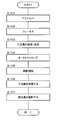
- control lever is operated to align the apparatus optical system with the eye to be examined (S101). This operation is performed, for example, by projecting a bright spot on the eye to be examined by the alignment optical system and operating the control lever so that the bright spot displayed on the screen is arranged in a bracket-shaped scale.
- the apparatus optical system is focused (focused) on a region of interest of the eye to be examined (for example, the macula, optic nerve head, etc.) (S102).
- This operation is performed, for example, by projecting a focusing target on the eye to be examined using a predetermined optical system and operating a focusing handle. More specifically, a split bright line composed of two straight bright lines is projected as a focus target, and the focusing handle is operated so that the two bright lines are arranged in a straight line. .
- the interference image is searched and displayed (S103).
- an interference image at a desired depth position of the fundus is displayed by adjusting the optical path length of the reference light.
- the optical path length is adjusted to improve the image quality at a desired depth position.
- the adjustment of the optical path length may be performed manually by an operator, or may be performed automatically by acquiring and analyzing an interference image.
- Auto-tracking is a technique for causing a light beam (signal light) to follow the movement of the eye to be inspected so that the region of interest is arranged approximately at the center of the interference image. This technique is disclosed in, for example, Patent Documents 7 to 10.
- the apparatus acquires an interference image (S106), and further captures a fundus image (S107).
- some conventional ophthalmologic photographing apparatuses such as a fundus camera have a function of automatically taking an image by determining the alignment or focus state, but this can be applied to an optical image measuring apparatus as it is.
- the present invention has been made to solve such a problem, and an object of the present invention is to provide an optical image measurement device capable of easily performing measurement without missing measurement timing.
- the invention according to claim 1 divides low-coherence light into signal light and reference light, and the signal light passing through the object to be measured and the reference light passing through the reference object
- An optical system that generates interference light by causing interference to be detected, generates a detection signal by detecting the interference light, and image forming means that forms a tomographic image of the object to be measured based on the detection signal
- An image measurement apparatus comprising: an alignment unit that aligns the optical system with respect to an object to be measured; a focusing unit that focuses the optical system with respect to a region of interest of the object to be measured; and the optical by the alignment unit Determining means for respectively determining the suitability of the position of the system, the suitability of the in-focus state by the focusing means, and the suitability of the position of the attention area formed by the image forming means within the frame.
- the invention according to claim 2 is the optical image measurement device according to claim 1, wherein the control means is one of the position of the optical system, the in-focus state, and the position in the frame. When it is determined that at least one of them is inappropriate, acquisition of a tomographic image of the object to be measured is prohibited.
- the invention according to claim 3 is the optical image measurement device according to claim 1, further comprising display means, wherein the control means includes the position of the optical system, the in-focus state, and the frame. Warning information is displayed on the display means when it is determined that at least one of the positions in the box is inappropriate.
- the invention according to claim 4 is the optical image measurement device according to claim 1, wherein the determination unit further analyzes a tomographic image formed by the image forming unit to analyze the tomographic image.
- the control means determines whether the optical system position, the in-focus state, the position in the frame, and the image quality of the tomographic image are all appropriate. It is possible to acquire a tomographic image of the region of interest by controlling the system and the image forming means.
- the invention according to claim 5 is the optical image measurement device according to claim 4, wherein the control means includes a position of the optical system, a focused state, a position in the frame, and the tomography.
- the acquisition of the tomographic image of the measured object is prohibited when it is determined that at least one of the image quality of the image is inappropriate.
- the invention according to claim 6 is the optical image measurement device according to claim 4, further comprising display means, wherein the control means includes the position of the optical system, the in-focus state, and the inside of the frame. Warning information is displayed on the display means when it is determined that at least one of the position and the image quality of the tomographic image is inappropriate.
- the invention described in claim 7 is the optical image measurement device according to claim 4, wherein the optical system includes a polarizing plate on an optical path of the reference light, and the control means includes the tomographic image.
- the polarizing plate is controlled so that the image quality is maximized when it is determined that the image quality is inappropriate.
- the invention according to claim 8 is the optical image measurement device according to claim 1, wherein the region of interest is approximately in the center of the frame based on the tomographic image formed by the image forming means.
- Tracking means for causing the irradiation position of the signal light on the object to be measured to follow the movement of the object to be measured so that a tomographic image is arranged, and the determination means further includes irradiation of the signal light. Determining whether the tracking state of the position is appropriate or not, and when the control unit determines that the position of the optical system, the in-focus state, the position in the frame, and the tracking state are all appropriate, It is possible to acquire a tomographic image of the region of interest by controlling an optical system and the image forming unit.
- the invention according to claim 9 is the optical image measurement device according to claim 1, wherein the two-dimensional image of the object to be measured in a plane substantially orthogonal to the traveling direction of the signal light with respect to the object to be measured. And an irradiation position of the signal light on the object to be measured so that a tomographic image of the region of interest is arranged at a substantially center in the frame, based on an imaging unit that captures the two-dimensional image.
- Tracking means for following the movement of the object to be measured, and the determination means further determines the suitability of the tracking state of the irradiation position of the signal light, and the control means is a position of the optical system, When it is determined that the in-focus state, the position in the frame, and the tracking state are all appropriate, the tomographic image of the region of interest can be acquired by controlling the optical system and the image forming unit. To do that And features.
- the invention according to claim 10 is the optical image measurement device according to claim 8 or claim 9, wherein the control means includes the position of the optical system, the in-focus state, and the position in the frame. And at least one of the following states is determined to be inappropriate, acquisition of a tomographic image of the object to be measured is prohibited.
- the invention according to claim 11 is the optical image measurement device according to claim 8 or 9, further comprising display means, wherein the control means includes the position of the optical system and the in-focus state. When at least one of the position in the frame and the following state is determined to be inappropriate, warning information is displayed on the display means.
- the invention according to claim 12 divides low-coherence light into signal light and reference light, and causes interference between the signal light passing through the object to be measured and the reference light passing through the reference object.
- An optical system that generates a detection signal by detecting the interference light and an image forming unit that forms a tomographic image of the object to be measured based on the detection signal.
- An alignment means for aligning the optical system with respect to the object to be measured; a focusing means for focusing the optical system with respect to a region of interest of the object to be measured; and a tomographic image formed by the image forming means.
- Tracking means for causing the irradiation position of the signal light to the object to be measured to follow the movement of the object to be measured so that a tomographic image of the region of interest is arranged at a substantially center in the frame; Determining the suitability of the position of the optical system by means, determining the suitability of the in-focus state by the focus means, and determining the suitability of the position of the tomographic image of the region of interest formed by the image forming means in the frame And determining the suitability of the image quality of the tomogram by analyzing the tomogram formed by the image forming means, and determining the suitability of the tracking state of the irradiation position of the signal light, and the position of the optical system
- the focus state, the position in the frame, the image quality of the tomographic image, and the tracking state are all determined to be appropriate, the optical system and the image forming unit are controlled to control the region of interest. And a control unit that enables acquisition of tomographic images.
- the low-coherence light is divided into signal light and reference light, and the signal light passing through the object to be measured and the reference light passing through the reference object interfere with each other to cause interference light.
- An optical system that detects the interference light and generates a detection signal, an image forming unit that forms a tomographic image of the object to be measured based on the detection signal, and the signal light for the object to be measured
- An optical image measuring device having a photographing means for photographing a two-dimensional image of the object to be measured in a plane substantially orthogonal to the traveling direction, the alignment means for aligning the optical system with respect to the object to be measured; Based on the focusing means for focusing the optical system on the target area of the object to be measured and the captured two-dimensional image, the tomographic image of the target area is arranged approximately at the center in the frame.
- the above The follow-up means for following the movement of the object to be measured with the irradiation position of the signal light with respect to the measurement object, the suitability of the position of the optical system by the alignment means, and the suitability of the focus state by the focus means are judged. And determining the appropriateness of the position of the tomographic image in the frame of the region of interest formed by the image forming means and analyzing the tomographic image formed by the image forming means to determine the appropriateness of the image quality of the tomographic image.
- determining means for determining the suitability of the follow-up state of the irradiation position of the signal light, and the position of the optical system, the in-focus state, the position in the frame, the image quality of the tomographic image, and the follow-up state are all And a control unit that controls the optical system and the image forming unit to obtain a tomographic image of the region of interest when it is determined to be appropriate.
- the invention described in claim 14 is the optical image measuring device according to any one of claims 1, 4, 8, 8, 9, 12, and 13,
- the control means controls the optical system and the image forming means to acquire a tomographic image of the region of interest when it is determined that all are appropriate.
- the optical image measurement apparatus includes a frame of a tomographic image of an attention area of an object to be measured formed by an image forming unit, and whether or not an optical system is properly positioned by an alignment unit. In this case, it is determined whether each position is appropriate or not, and when it is determined that all three conditions are appropriate, a tomographic image of the region of interest can be acquired.
- another aspect of the optical image measurement device determines whether the image quality of the tomographic image is appropriate and whether the tracking state of the irradiation position of the signal light is appropriate. It is possible to acquire a tomographic image of a region of interest when it is determined that all of these are appropriate.
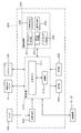
- Optical Image Measuring Device 1A Fundus Camera Unit 100 Illumination Optical System 120 Imaging Optical System 141 Scanning Unit 150 OCT Unit 160 Low Coherence Light Source 174 Reference Mirror 180 Spectrometer 184 CCD 190A alignment optical system 200 arithmetic control unit 210 control unit 220 image forming unit 230 image processing unit 231 alignment determination unit 232 focus determination unit 233 image position determination unit 234 image quality determination unit 235 tracking determination unit 240 display unit 250 operation unit 309 alignment scale 310 alignment bright spot 311 split bright line
- the configuration according to this embodiment can be applied to any type of OCT technology that scans signal light such as a swept source type.
- the configuration according to this embodiment can be applied to an OCT technique in which signal light is not scanned in the horizontal direction as in the full field type.
- the optical image measurement device 1 includes a fundus camera unit 1 ⁇ / b> A, an OCT unit 150, and an arithmetic control device 200. Each of these units may be provided in a distributed manner in a plurality of cases, or may be provided in a single case.
- the fundus camera unit 1A has an optical system that is substantially the same as that of a conventional fundus camera.
- a fundus camera is a device that photographs the fundus.
- the fundus camera is used for photographing a fundus blood vessel.
- the OCT unit 150 stores an optical system for acquiring an OCT image of the eye to be examined.
- the arithmetic and control unit 200 includes a computer that executes various arithmetic processes and control processes.
- connection line 152 One end of a connection line 152 is attached to the OCT unit 150.
- a connector 151 for connecting the connection line 152 to the retinal camera unit 1A is attached to the other end of the connection line 152.
- An optical fiber 152a is conducted inside the connection line 152 (see FIG. 3).
- the OCT unit 150 and the fundus camera unit 1A are optically connected via a connection line 152.
- the arithmetic and control unit 200 is connected to each of the fundus camera unit 1A and the OCT unit 150 via a communication line that transmits an electrical signal.
- the fundus camera unit 1A includes an optical system for forming a two-dimensional image representing the form of the fundus surface.
- the two-dimensional image of the fundus surface includes a color image and a monochrome image obtained by photographing the fundus surface, and further a fluorescent image (fluorescein fluorescent image, indocyanine green fluorescent image, etc.) and the like.
- the retinal camera unit 1A is provided with various user interfaces as in the conventional retinal camera.
- the user interface include an operation panel, a control lever (joystick), a photographing switch, a focusing handle, a display, and the like.
- Various switches and buttons are provided on the operation panel.
- the control lever is operated to three-dimensionally move a gantry provided with an operation panel or the like, or an apparatus main body incorporating an optical system with respect to the apparatus base.
- the control lever is used particularly during manual alignment operations.
- the imaging switch is provided at the upper end of the control lever, and is used to instruct acquisition of a fundus image or an OCT image.
- the photographing switch is also used when performing other functions.
- the operation panel and the control lever are provided at the position (rear surface) on the examiner side of the fundus camera unit 1A.
- the focusing handle is provided on the side surface of the apparatus main body, for example, and is used for focus adjustment (focusing). When the focusing handle is operated, a focusing lens described later is moved to change the focus state.
- the display is provided at a position on the examiner side of the fundus camera unit 1 ⁇ / b> A and displays various information such as an image acquired by the optical image measurement device 1, patient information, and imaging conditions.
- a chin rest and a forehead for holding the face of the subject are provided at a position (front surface) on the subject side of the fundus camera unit 1A.
- the fundus camera unit 1A is provided with an illumination optical system 100 and a photographing optical system 120 as in the case of a conventional fundus camera.
- the illumination optical system 100 irradiates the fundus oculi Ef with illumination light.
- the imaging optical system 120 guides the fundus reflection light of the illumination light to the imaging devices 10 and 12.
- the imaging optical system 120 guides the signal light from the OCT unit 150 to the fundus oculi Ef and guides the signal light passing through the fundus oculi Ef to the OCT unit 150.
- the illumination optical system 100 includes an observation light source 101, a condenser lens 102, a photographing light source 103, a condenser lens 104, exciter filters 105 and 106, a ring translucent plate 107, a mirror 108, an LCD (Liquid Crystal Display), as in a conventional fundus camera. ) 109, an illumination aperture 110, a relay lens 111, a perforated mirror 112, and an objective lens 113.
- the observation light source 101 outputs illumination light including wavelengths in the near-infrared region, for example, in the range of about 700 nm to 800 nm. This near-infrared light is set shorter than the wavelength of light used in the OCT unit 150 (described later).
- the imaging light source 103 outputs illumination light including a wavelength in the visible region in the range of about 400 nm to 700 nm, for example.
- the illumination light output from the observation light source 101 is perforated through condenser lenses 102 and 104, (exciter filter 105 or 106) ring translucent plate 107, mirror 108, reflector 109 b, illumination diaphragm 110, and relay lens 111.
- the mirror 112 is reached. Further, the illumination light is reflected by the perforated mirror 112 and enters the eye E through the objective lens 113 to illuminate the fundus oculi Ef.
- the illumination light output from the imaging light source 103 similarly enters the eye E through the condenser lens 104 to the objective lens 113 and illuminates the fundus oculi Ef.
- the photographing optical system 120 includes an objective lens 113, a perforated mirror 112 (hole 112a), a photographing aperture 121, barrier filters 122 and 123, a focusing lens 124, a relay lens 125, a photographing lens 126, a dichroic mirror 134, and a field lens. (Field lens) 128, half mirror 135, relay lens 131, dichroic mirror 136, photographing lens 133, imaging device 10, reflection mirror 137, photographing lens 138, imaging device 12, lens 139 and LCD 140 are configured.
- the photographing optical system 120 has substantially the same configuration as a conventional fundus camera.
- the focusing lens 124 is movable in the optical axis direction of the photographing optical system 120.
- the dichroic mirror 134 reflects the fundus reflection light (having a wavelength included in the range of about 400 nm to 800 nm) of the illumination light from the illumination optical system 100.
- the dichroic mirror 134 transmits the signal light LS (for example, having a wavelength included in the range of about 800 nm to 900 nm; see FIG. 3) from the OCT unit 150.
- the dichroic mirror 136 reflects the fundus reflection light of the illumination light from the observation light source 101 and transmits the fundus reflection light of the illumination light from the imaging light source 103.
- the LCD 140 displays a fixation target (internal fixation target) for fixing the eye E to be examined.
- a fixation target (internal fixation target) for fixing the eye E to be examined.
- Light from the LCD 140 is collected by the lens 139, reflected by the half mirror 135, and reflected by the dichroic mirror 136 via the field lens 128. Further, this light is incident on the eye E through the photographing lens 126, the relay lens 125, the focusing lens 124, the aperture mirror 112 (the aperture 112a thereof), the objective lens 113, and the like. Thereby, the internal fixation target is projected onto the fundus oculi Ef.
- the fixation direction of the eye E can be changed by changing the display position of the internal fixation target on the LCD 140.
- As the fixation direction of the eye E for example, as with a conventional fundus camera, a fixation direction for acquiring an image centered on the macular portion of the fundus oculi Ef or an image centered on the optic disc is acquired. And the fixation direction for acquiring an image centered on the fundus center between the macula and the optic disc.
- the fixation position is changed, for example, by operating the operation panel.
- the imaging device 10 includes an imaging element 10a.
- the imaging device 10 can particularly detect light having a wavelength in the near infrared region. That is, the imaging device 10 functions as an infrared television camera that detects near-infrared light.
- the imaging device 10 detects near infrared light and outputs a video signal.
- the imaging element 10a is an arbitrary imaging element (area sensor) such as a CCD (Charge Coupled Devices) or a CMOS (Complementary Metal Oxide Semiconductor).
- the imaging device 12 includes an imaging element 12a.
- the imaging device 12 can particularly detect light having a wavelength in the visible region. That is, the imaging device 12 functions as a television camera that detects visible light.
- the imaging device 12 detects visible light and outputs a video signal.
- the image sensor 12a is configured by an arbitrary image sensor (area sensor), similarly to the image sensor 10a.
- the touch panel monitor 11 displays the fundus oculi image Ef ′ based on the video signals from the image sensors 10a and 12a.
- the video signal is sent to the arithmetic and control unit 200.
- the touch panel monitor 11 is an example of the display described above.
- the fundus camera unit 1A is provided with a scanning unit 141 and a lens 142.
- the scanning unit 141 scans the irradiation position of the signal light LS output from the OCT unit 150 to the fundus oculi Ef.
- the scanning unit 141 scans the signal light LS on the xy plane shown in FIG.
- the scanning unit 141 is provided with, for example, a galvanometer mirror for scanning in the x direction and a galvanometer mirror for scanning in the y direction.
- the reflector 109b of the illumination optical system 100 constitutes a focusing optical system together with the LED 109a.
- the focusing optical system projects a visual target (split bright line) used for focus adjustment onto the eye E as in a conventional fundus camera.
- the reflecting rod 109b can be inserted into and removed from the optical axis of the illumination optical system 100.
- One end of the reflecting rod 109 b has a reflecting surface that is inclined with respect to the optical axis of the illumination optical system 100.
- the output light from the LED 109a is reflected by the reflecting surface and projected onto the eye E through the same path as the illumination light.
- the focusing optical system is moved in the optical axis direction of the illumination optical system 100 in conjunction with the movement of the focusing lens 124 so that the reflecting surface of the reflecting bar 109b and the fundus oculi Ef are optically conjugate. .
- the pair of split bright lines appear to be separated in the left-right direction without being aligned on a straight line.
- the reflecting surface and the fundus oculi Ef are conjugated, the pair of split bright lines appear to be aligned. Focus adjustment can be performed using this. Such focus adjustment using split emission lines is widely used in conventional fundus cameras and the like.
- a half mirror 190 is obliquely installed on the optical path between the focusing lens 124 and the relay lens 125.
- the half mirror 190 acts to synthesize the optical path of the alignment optical system 190A shown in FIG. 2A and the optical path of the imaging optical system 120 (imaging optical path).
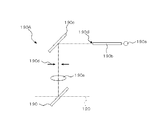
- the alignment optical system 190A is an optical system for projecting the alignment bright spot used for the alignment (alignment) of the optical system with respect to the eye E to the eye E.
- the alignment bright spot is an alignment (alignment in the xy direction shown in FIG. 1) that aligns the apex of the cornea of the eye E with the optical axes of the optical systems 100 and 120, and the distance between the eye E and the optical systems 100 and 120. (Z direction in FIG. 1; working distance; distance between the cornea (apex) of the eye E and the objective lens 113) (for example, Japanese Patent Laid-Open No. 11-4808) reference).
- the alignment optical system 190A includes an alignment light source 190a, a light guide 190b, a reflection mirror 190c, a two-hole aperture 190d, and a relay lens 190e together with the half mirror 190.
- the alignment light source 190a is configured by a light source such as an LED that outputs light in the near infrared region (alignment light), for example.
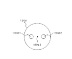
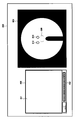
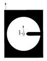
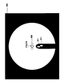
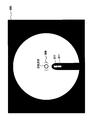
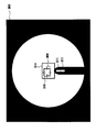
- the two-hole aperture 190d has two holes 190d1 and 190d2 as shown in FIG. 2B.
- the holes 190d1 and 190d2 are formed at positions symmetrical with respect to the center position 190d3 of the disc-shaped two-hole aperture 190d, for example.
- the two-hole aperture 190d is disposed such that the center position 190d3 is positioned on the optical axis of the alignment optical system 190A.
- Alignment light emitted from the emission end 190 ⁇ of the light guide 190b is reflected by the reflection mirror 190c and guided to the two-hole aperture 190d.
- the alignment light (a part) that has passed through the holes 190d1 and 190d2 of the two-hole aperture 190d is reflected by the half mirror 190 and guided to the perforated mirror 112 via the relay lens 190e.
- the relay lens 190e forms an intermediate image of the image of the exit end 190 ⁇ of the light guide 190b at the center position of the hole 112a of the perforated mirror 112 (position on the optical axis of the photographing optical system 120).
- the alignment light that has passed through the hole 112 a of the perforated mirror 112 is projected onto the cornea of the eye E through the objective lens 113.
- the positional relationship between the eye E and the fundus camera unit 1A is appropriate, that is, the distance (working distance) between the eye E and the fundus camera unit 1A is appropriate.
- the optical axis of the optical system of the fundus camera unit 1A and the eye axis (corneal apex position) of the eye E to be examined are (almost) coincident, two light beams (alignment light beams) formed by the two-hole aperture 190d Are projected on the eye E to be imaged at intermediate positions between the apex of the cornea and the center of curvature of the cornea.
- the corneal reflection light of the two alignment light beams is received by the image sensor 10a via the photographing optical system 120.
- An image captured by the image sensor 10a is displayed on a display device such as a touch panel monitor 11 or a display (described later) of the arithmetic and control unit 200.
- This display screen is displayed on the touch panel monitor 11, for example.
- Information presented on this display screen includes patient ID 301; left and right eye information 302, photographing light source charging information 303, photographing light amount correction information 304, photographing light amount level information 305, automatic photographing information 306, angle of view information 307, fixation position.
- Left and right eye information 302 is information indicating whether the eye E is the left eye (L) or the right eye (R).
- the imaging light source charging information 303 is information representing the charging state of the imaging light source 103 (xenon lamp).
- the photographing light amount correction information 304 is information representing a photographing light amount correction value set on the operation panel.
- the photographing light amount level information 305 is information representing a setting value of the photographing light amount.
- the automatic shooting information 306 is presented when a function for automating shooting work such as autoshoot (automatic shooting) or autofocus is turned on.
- the angle-of-view information 307 is information representing a set value of a shooting angle of view (shooting magnification).
- the fixation position information 308 is information representing a set value of the fixation position (fixation direction) of the eye E.
- the observation light quantity level information 312 is information representing a set value of the observation light quantity.
- the small pupil information 313 is presented when a small pupil diaphragm (not shown) used when the eye E is a small pupil is applied.
- the pair of alignment bright spots 310 are light reception images of light projected onto the eye E by the alignment optical system 190A.
- the alignment scale 309 is a parenthesis-type image that represents a position that is a movement target of the pair of alignment bright spots 310.
- the examiner performs the alignment of the optical system with respect to the eye E by operating the control lever and moving the fundus camera unit 1 ⁇ / b> A three-dimensionally so that the pair of alignment bright spots 310 enter the alignment scale 309. .
- each alignment luminescent spot 310 in the display screen is specified, a shift between each specified position and the alignment scale 309 is obtained, and the fundus camera unit 1A is moved so as to cancel this shift. To do so.
- the position of each alignment bright spot 310 can be determined by, for example, obtaining the brightness distribution of each alignment bright spot and obtaining the center of gravity position based on this brightness distribution. Since the position of the alignment scale 309 is constant, the deviation can be obtained by obtaining the displacement between the center position and the gravity center position, for example.
- the movement direction and movement distance of the fundus camera unit 1A are set as unit movement distances in each of the preset x, y, and z directions (for example, how much the fundus camera unit 1A is moved in which direction and how much the alignment brightness is increased). It is possible to determine with reference to a result of measuring in advance in which direction and how much the point 310 moves.
- an actuator such as a pulse motor for moving the fundus camera unit 1A is provided.
- the pair of split bright lines 311 are presented side by side in the vertical direction.
- the examiner operates the focusing handle to move the focusing lens 124 and the focusing optical system in order to perform focus adjustment. Accordingly, the upper and lower split bright lines 311 move in the left-right direction.
- the examiner performs focusing by operating the focusing handle so that the upper and lower split bright lines 311 are positioned on a straight line extending vertically.
- Autofocus is performed, for example, by specifying the display position of each split bright line 311 and determining the moving direction and moving distance of the focusing lens 124 and the like so that the upper and lower split bright lines 311 are positioned on a straight line.
- the display position of each split bright line 311 can be determined by, for example, obtaining the barycentric position from the luminance distribution of each split bright line 311.
- the moving direction and moving distance are, for example, preset unit moving distances (for example, how much the focusing lens 124 is moved in which direction and how much the split bright line 311 moves in which direction and how much in advance. It is possible to determine with reference to the measurement result).
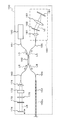
- the OCT unit 150 includes an optical system similar to that of a conventional Fourier domain type optical image measurement device. That is, the OCT unit 150 divides low-coherence light into reference light and signal light, and generates interference light by causing the signal light passing through the fundus of the eye to be examined and the reference light passing through the reference object to generate interference light. An optical system for detecting light and generating a detection signal is provided. This detection signal is sent to the arithmetic and control unit 200.
- the low coherence light source 160 is a broadband light source that outputs a broadband low coherence light L0.
- a broadband light source for example, a super luminescent diode (SLD), a light emitting diode (LED), or the like can be used.
- SLD super luminescent diode
- LED light emitting diode
- the low coherence light L0 includes, for example, light having a wavelength in the near infrared region, and has a temporal coherence length of about several tens of micrometers.
- the low coherence light L0 includes a wavelength longer than the illumination light (wavelength of about 400 nm to 800 nm) of the fundus camera unit 1A, for example, a wavelength in the range of about 800 nm to 900 nm.
- the low coherence light L0 output from the low coherence light source 160 is guided to the optical coupler 162 through the optical fiber 161.
- the optical fiber 161 is configured by, for example, a single mode fiber, a PM fiber (Polarization maintaining fiber), or the like.
- the optical coupler 162 splits the low coherence light L0 into the reference light LR and the signal light LS.
- the optical coupler 162 has both functions of a means for splitting light (splitter) and a means for superposing light (coupler), but here it is conventionally referred to as an “optical coupler”.
- the reference light LR generated by the optical coupler 162 is guided by an optical fiber 163 made of a single mode fiber or the like and emitted from the end face of the fiber. Further, the reference light LR is converted into a parallel light beam by the collimator lens 171 and is reflected by the reference mirror 174 via the glass block 172, the polarizing plate ( ⁇ / 4 plate) 175 and the density filter 173.
- the reference mirror 174 is an example of the “reference object” in the present invention.
- the reference light LR reflected by the reference mirror 174 passes through the density filter 173, the polarizing plate 175, and the glass block 172 again, is condensed on the fiber end surface of the optical fiber 163 by the collimator lens 171, and passes through the optical fiber 163 to the optical coupler 162. Led to.
- the glass block 172 and the density filter 173 act as delay means for matching the optical path lengths (optical distances) of the reference light LR and the signal light LS. Further, the glass block 172 and the density filter 173 function as dispersion compensation means for matching the dispersion characteristics of the reference light LR and the signal light LS.
- the density filter 173 acts as a neutral density filter that reduces the amount of the reference light LR.
- the density filter 173 is configured by, for example, a rotary ND (Neutral Density) filter.
- the density filter 173 is rotationally driven by a drive mechanism (not shown) to change the amount of the reference light LR that contributes to the generation of the interference light LC.
- the polarizing plate 175 is used to correct the optical path length of the reference light LR and is used to improve the image quality of the OCT image.
- the polarizing plate 175 is disposed so as to be inclined by, for example, about 3 degrees with respect to the direction orthogonal to the optical path direction of the reference light LR.
- the polarizing plate 175 is rotationally driven by a predetermined driving mechanism, thereby adjusting the image quality of the interference image.
- the reference mirror 174 is moved in the traveling direction of the reference light LR (in the direction of the double-sided arrow shown in FIG. 3) by a predetermined driving mechanism. Thereby, the optical path length of the reference light LR can be ensured according to the axial length of the eye E and the working distance (distance between the objective lens 113 and the eye E).
- the signal light LS generated by the optical coupler 162 is guided to the end of the connection line 152 by an optical fiber 164 made of a single mode fiber or the like.
- the optical fiber 164 and the optical fiber 152a may be formed from a single optical fiber, or may be formed integrally by joining the respective end faces.
- the signal light LS is guided by the optical fiber 152a and guided to the fundus camera unit 1A. Further, the signal light LS includes the lens 142, the scanning unit 141, the dichroic mirror 134, the photographing lens 126, the relay lens 125, the half mirror 190, the focusing lens 124, the photographing aperture 121, the hole 112a of the aperture mirror 112, the objective lens.
- the eye E is irradiated to the eye E via 113 and irradiated to the fundus Ef.
- the barrier filters 122 and 123 are retracted from the optical path in advance.
- the signal light LS incident on the eye E is imaged and reflected on the fundus oculi Ef.
- the signal light LS is not only reflected by the surface of the fundus oculi Ef, but also reaches the deep region of the fundus oculi Ef and is scattered at the refractive index boundary. Therefore, the signal light LS passing through the fundus oculi Ef includes information reflecting the surface form of the fundus oculi Ef and information reflecting the state of backscattering at the refractive index boundary of the deep tissue of the fundus oculi Ef. This light may be simply referred to as “fundus reflected light of the signal light LS”.
- the fundus reflection light of the signal light LS is guided in the reverse direction along the same path as the signal light LS toward the eye E to be collected on the end surface of the optical fiber 152a. Further, the fundus reflection light of the signal light LS enters the OCT unit 150 through the optical fiber 152 a and returns to the optical coupler 162 through the optical fiber 164.
- the optical coupler 162 superimposes the signal light LS returned via the fundus oculi Ef and the reference light LR reflected by the reference mirror 174 to generate interference light LC.
- the interference light LC is guided to the spectrometer 180 through an optical fiber 165 made of a single mode fiber or the like.
- a spectrometer (spectrometer) 180 detects a spectral component of the interference light LC.
- the spectrometer 180 includes a collimator lens 181, a diffraction grating 182, an imaging lens 183, and a CCD 184.
- the diffraction grating 182 may be transmissive or reflective. Further, in place of the CCD 184, other light detection elements (line sensor or area sensor) such as CMOS may be used.
- the interference light LC incident on the spectrometer 180 is converted into a parallel light beam by the collimator lens 181 and split (spectral decomposition) by the diffraction grating 182.
- the split interference light LC is imaged on the imaging surface of the CCD 184 by the imaging lens 183.
- the CCD 184 detects each spectral component of the separated interference light LC and converts it into electric charges.
- the CCD 184 accumulates this electric charge and generates a detection signal. Further, the CCD 184 sends this detection signal to the arithmetic and control unit 200.
- a Michelson interferometer is used.
- any type of interferometer such as a Mach-Zehnder type can be appropriately used.
- the configuration of the arithmetic and control unit 200 will be described.
- the arithmetic and control unit 200 analyzes the detection signal input from the CCD 184 and forms an OCT image of the fundus oculi Ef.
- the arithmetic processing for this is the same as that of a conventional Fourier domain type optical image measurement device.
- the arithmetic and control unit 200 controls each part of the fundus camera unit 1A and the OCT unit 150.
- the arithmetic control device 200 controls the output of illumination light by the observation light source 101 and the imaging light source 103, and controls the insertion / retraction operation of the exciter filters 105 and 106 and the barrier filters 122 and 123 on the optical path.
- Operation control of display device such as LCD 140, movement control of illumination diaphragm 110 (control of aperture value), control of aperture value of photographing diaphragm 121, movement control of focusing lens 124 (focus adjustment, magnification adjustment), focusing optics
- the system and alignment optical system 190A are controlled.
- the arithmetic and control unit 200 controls the scanning unit 141 to scan the signal light LS.
- the arithmetic and control unit 200 controls the output of the low coherence light L0 by the low coherence light source 160, the movement control of the reference mirror 174, and the rotation operation of the density filter 173 (the amount of decrease in the light amount of the reference light LR). Control), charge accumulation time by CCD 184, charge accumulation timing, signal transmission timing, and the like.
- the arithmetic and control unit 200 includes a microprocessor, a RAM, a ROM, a hard disk drive, a keyboard, a mouse, a display, a communication interface, and the like, like a conventional computer.
- the hard disk drive stores a computer program for controlling the optical image measurement device 1.
- the arithmetic and control unit 200 may include a dedicated circuit board that forms an OCT image based on a detection signal from the CCD 184.
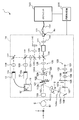
- Control system The configuration of the control system of the optical image measurement device 1 will be described with reference to FIG. 5, the imaging devices 10 and 12 are described separately from the fundus camera unit 1A, and the CCD 184 is described separately from the OCT unit 150. However, as described above, the imaging devices 10 and 12 are included in the fundus oculi. Mounted on the camera unit 1 ⁇ / b> A, the CCD 184 is mounted on the OCT unit 150.
- the control system of the optical image measurement device 1 is configured around the control unit 210 of the arithmetic and control device 200.
- the control unit 210 includes, for example, the aforementioned microprocessor, RAM, ROM, hard disk drive, communication interface, and the like.
- the control unit 210 is an example of the “control unit” in the present invention.
- the control unit 210 is provided with a main control unit 211 and a storage unit 212.
- the main control unit 211 controls each part of the fundus camera unit 1 ⁇ / b> A, the OCT unit 150, and the arithmetic control device 200.
- the storage unit 212 stores various data. Examples of data stored in the storage unit 212 include image data of an OCT image, image data of a fundus oculi image Ef ′, and eye information to be examined.
- the eye information includes, for example, various information related to the eye such as information about the subject such as patient ID and name, left eye / right eye identification information, and diagnosis / test results of the eye.
- the main control unit 211 performs a process of writing data to the storage unit 212 and a process of reading data from the storage unit 212.
- the storage unit 212 stores data of unit movement distance (described above) in alignment adjustment and focus adjustment. Further, the storage unit 212 stores a computer program for executing an operation (flow chart) described later. The main control unit 211 operates based on the data and the computer program.
- the image forming unit 220 forms tomographic image data of the fundus oculi Ef based on the detection signal from the CCD 184.
- This image data forming process includes processes such as noise removal (noise reduction), filter processing, and FFT (Fast Fourier Transform), as in the conventional Fourier domain type OCT technique.
- the image forming unit 220 includes, for example, the above-described circuit board and communication interface.
- the image forming unit 220 is an example of the “image forming unit” in the present invention.
- image data and “image” displayed based on the “image data” may be identified.
- the image processing unit 230 performs various types of image processing and analysis processing on the fundus image (captured image of the fundus surface) acquired by the fundus camera unit 1A and the tomographic image formed by the image forming unit 220. For example, the image processing unit 230 executes various correction processes such as image brightness correction and dispersion correction.
- the image processing unit 230 forms image data of a three-dimensional image of the fundus oculi Ef by executing interpolation processing for interpolating pixels between tomographic images formed by the image forming unit 220.
- the image data of a three-dimensional image means image data in which pixel positions are defined by a three-dimensional coordinate system.
- image data of a three-dimensional image there is image data composed of voxels arranged three-dimensionally. This image data is called volume data or voxel data.
- the image processing unit 230 When displaying an image based on the volume data, the image processing unit 230 performs rendering processing (volume rendering, MIP (Maximum Intensity Projection), etc.) on the volume data, and views the image from a specific line-of-sight direction.
- rendering processing volume rendering, MIP (Maximum Intensity Projection), etc.
- MIP Maximum Intensity Projection
- the stack data is image data obtained by three-dimensionally arranging a plurality of tomographic images obtained along a plurality of scanning lines based on the positional relationship of the scanning lines. That is, the stack data is image data obtained by expressing a plurality of tomographic images originally defined by individual two-dimensional coordinate systems using one three-dimensional coordinate system (that is, embedding in one three-dimensional space). is there.
- the image processing unit 230 can also perform various image processing and analysis processing on the three-dimensional image.
- the image processing unit 230 includes an alignment determination unit 231, an in-focus determination unit 232, an image position determination unit 233, an image quality determination unit 234, and a tracking determination unit 235.
- Each of the determination units 231 to 235 constitutes a part of “determination means” of the present invention.
- the alignment determination unit 231 determines whether the position of the optical system is appropriate, that is, whether the optical system is positioned at an appropriate position with respect to the eye E at a predetermined timing after the alignment adjustment of the optical system. As described above, the alignment determination unit 231 determines the suitability of the alignment state at a predetermined timing after alignment adjustment. Even after the alignment adjustment, the alignment state may change due to the eye movement of the eye E, the movement of the subject, and the like, so such alignment determination is effective.
- the alignment determination unit 231 analyzes the fundus image of the eye E acquired in a state where the alignment bright spot 310 is projected after the alignment adjustment (see FIG. 4).
- the position of the alignment scale 309 in the fundus image frame is known (constant).
- the alignment determination unit 231 specifies the positions (center of gravity positions, etc.) of the pair of alignment bright spots 310 in the manner described above. Subsequently, the alignment determination unit 231 determines whether or not these specific positions are within a predetermined allowable range, that is, within the alignment scale 309 (parenthesis-shaped image). When it is determined that these specific positions are within the allowable range, the alignment determination unit 231 determines that the alignment state is appropriate. On the other hand, when these specific positions are not within the allowable range, the alignment determination unit 231 determines that the alignment state is not appropriate.
- a specific example of processing for determining the suitability of the alignment state is described in, for example, Japanese Patent Application No. 2008-13989 by the present applicant.
- the focus determination unit 232 determines whether or not the focus state is appropriate, that is, whether or not the fundus oculi Ef is properly focused (whether or not the focus is in focus) at a predetermined timing after focus adjustment. . Even after the focus adjustment, the alignment state is effective because the focus state may change due to the eye movement of the eye E or the movement of the subject.
- the in-focus determination unit 232 analyzes the fundus image of the eye E acquired with the split bright line 311 projected after focus adjustment (see FIG. 4).
- the focus determination unit 232 specifies the position (center of gravity position) of the upper and lower split bright lines 311 in the left-right direction in the manner described above. Subsequently, the focus determination unit 232 determines whether these specific positions are within an allowable range in the left-right direction. This allowable range is set in advance. Thereby, it is determined whether or not the upper and lower split bright lines 311 are arranged on a substantially straight line. When it is determined that these specific positions are within the allowable range, the focus determination unit 232 determines that the focus state is appropriate. On the other hand, when these specific positions are not within the allowable range, the focus determination unit 232 determines that the focus state is not appropriate.
- a specific example of the process for determining the suitability of the focus state is described in, for example, Japanese Patent Application No. 2008-13989 by the present applicant.
- the image position determination unit 233 determines whether the position of the tomographic image of the fundus oculi Ef within the frame is appropriate. In particular, the image position determination unit 233 determines whether or not the depth position (position in the z direction) of the tomographic image in the frame is appropriate.
- the image position determination unit 233 specifies the position in the z direction within the frame of the image corresponding to the fundus surface. A specific example of this process will be described.
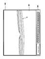
- the tomographic image is composed of a plurality of one-dimensional images extending in the depth direction. These one-dimensional images are arranged along the scanning line of the signal light LS.
- the frame of the tomographic image is black (luminance value 0), and the pixel corresponding to the fundus tissue (layer) has a luminance value corresponding to the intensity of the reflected light at that site. A portion having a depth that does not reach the signal light LS is expressed in black. That is, the tomographic image is an image in which various layers of the fundus are expressed in gray scale in a black frame.
- the tomographic image may be a pseudo color image corresponding to the luminance value.
- the image position determination unit 233 specifies a pixel corresponding to the fundus surface based on the luminance value of the pixel constituting each one-dimensional image. Thereby, the pixel group arranged along the scanning direction of the signal light LS is specified. This pixel group is an image area corresponding to the fundus surface.
- the specific target is not limited to the fundus surface, and may be a high-luminance part such as IS / OS.
- the image position determination unit 233 determines whether the specified pixel group is within an allowable range in the z direction. This allowable range is set in advance. When the pixel group is within the allowable range, the image position determination unit 233 determines that the depth position of the tomographic image in the frame is appropriate. On the other hand, when the pixel group is not within the allowable range, the image position determination unit 233 determines that the depth position of the tomographic image in the frame is not appropriate.
- the upper end region (image region corresponding to the fundus surface) and the lower end region (image region corresponding to the latest arrival depth of the signal light LS) of the tomographic image are included in the frame, that is, the upper end region and the lower end region are included.
- the position of the tomographic image may be determined so as not to be cut off from the frame. For this purpose, for example, in each one-dimensional image, it is determined whether or not the luminance values of the upper and lower vicinity regions of the frame are 0, and further whether or not there is a pixel group whose luminance value is not 0. What should I do?
- the image quality determination unit 234 analyzes the tomographic image of the fundus oculi Ef and determines whether the image quality of the tomographic image is appropriate. There are various image quality evaluation methods. An example will be described below.
- the image quality determination unit 234 specifies the pixel with the maximum luminance and the pixel with the minimum luminance for each one-dimensional image in the depth direction constituting the tomographic image.
- the image quality determination unit 234 creates a luminance value histogram (for example, 8 bits) based on the luminance value of a predetermined range of pixel groups (for example, 40 pixels before and after) including each identified pixel.
- the image quality determination unit 234 searches for the maximum position (luminance value) where the frequency value exceeds 0 in the histogram corresponding to the pixel group including the pixel having the minimum luminance. Further, in the histogram corresponding to the pixel group including the pixel having the maximum luminance, the total number of pixels (N) included in the range equal to or less than the luminance value searched above and the 255th luminance value from the top above the searched luminance value. And the total number of pixels (S) included in.
- the image quality determination unit 234 evaluates the percentage of the portion that can be regarded as a signal (that is, the portion that can be regarded as not noise) in the tomographic image by the following arithmetic expression: 100 ⁇ S ⁇ (S + N) . Such calculation processing is executed for each one-dimensional image, and an average value of these calculation results is used as an evaluation value of image quality.
- the image quality determination unit 234 determines whether the evaluation value thus obtained is equal to or greater than a predetermined threshold value. This threshold is set in advance. When it is determined that the evaluation value is equal to or greater than the threshold value, the image quality determination unit 234 determines that the image quality is appropriate. On the other hand, when it is determined that the evaluation value is less than the threshold value, the image quality determination unit 234 determines that the image quality is not appropriate.
- the tracking determination unit 235 determines whether or not the tracking state is appropriate when tracking (following) the irradiation position of the signal light LS with respect to the attention area (OCT image acquisition target area) of the fundus oculi Ef. That is, the tracking determination unit 235 determines whether or not tracking of the irradiation position of the signal light LS is appropriately executed for the eye movement of the eye E or the like.
- the tracking can be executed by controlling the galvanometer mirror in the scanning unit 141.
- the position of the fundus characteristic part (optic nerve head, etc.) in each frame of the moving image is specified, and this specified position is always the same position (frame center region, etc.)
- the irradiation position of the signal light LS is controlled so as to be disposed at the position.
- a predetermined scanning pattern for example, a cross scan
- a feature shape for example, a concave shape of a macular depicted by a pair of sequentially obtained tomographic images.
- the irradiation position of the signal light LS is controlled so that the feature points (for example, the macular center) are always arranged at the same position (frame center region or the like).
- tracking based on an OCT image is desirable because tracking by a fundus image may be insufficient.
- the target site for OCT measurement is set by selecting an internal fixation target (macular, optic nerve head, etc.).
- the tracking determination unit 235 determines whether or not the tracking state is appropriate by determining whether or not the tracking target part is included in the scanning region of the signal light LS.
- the scanning area is set to a predetermined area (such as a 6 mm ⁇ 6 mm square area) centered on the optical axis of the photographing optical system 120, for example. Further, the position of the tracking target part can be obtained with high accuracy by tracking using the above-described OCT image, for example.
- the signal light LS is applied to the eye E along the same optical axis (optical axis of the imaging optical system 120) as illumination light for fundus photography, and the fundus reflection light is also guided along the optical axis.
- the frame center of the fundus image coincides with the center position of the scanning region.
- the image processing unit 230 having the above configuration includes, for example, a microprocessor, a RAM, a ROM, a hard disk drive, and the like. Further, a circuit board that specializes in predetermined image processing and analysis processing may be included.
- the display unit 240 includes the touch panel monitor 11. Furthermore, a display of the arithmetic and control unit 200 may be included in the display unit 240.
- the display unit 240 is an example of the “display unit” in the present invention.
- the operation unit 250 includes an input device and an operation device such as a keyboard and a mouse. In addition, the operation unit 250 includes various input devices and operation devices provided on the surface of the casing of the optical image measurement device 1 or on the outside.
- the display unit 240 and the operation unit 250 need not be configured as individual devices.
- a device in which the display unit 240 and the operation unit 250 are integrated, such as a touch panel LCD, can be used.
- the scanning mode of the signal light LS by the optical image measuring device 1 includes, for example, horizontal scanning, vertical scanning, cross scanning, radiation scanning, circular scanning, concentric scanning, and helical scanning. These scanning modes are selectively used as appropriate in consideration of the observation site of the fundus, the analysis target (such as retinal thickness), the time required for scanning, the precision of scanning, and the like.
- the horizontal scan is to scan the signal light LS in the horizontal direction (x direction).
- the horizontal scan also includes an aspect in which the signal light LS is scanned along a plurality of horizontal scanning lines arranged in the vertical direction (y direction). In this aspect, it is possible to arbitrarily set the scanning line interval. By sufficiently narrowing the interval between the scanning lines, the above-described three-dimensional image can be formed (three-dimensional scan). The same applies to the vertical scan.
- the cross scan scans the signal light LS along a cross-shaped trajectory composed of two linear trajectories (straight trajectories) orthogonal to each other.
- the signal light LS is scanned along a radial trajectory composed of a plurality of linear trajectories arranged at a predetermined angle.
- the cross scan is an example of a radiation scan.
- the circle scan scans the signal light LS along a circular locus.
- the signal light LS is scanned along a plurality of circular trajectories arranged concentrically around a predetermined center position.
- a circle scan is considered a special case of a concentric scan.
- the spiral scan scans the signal light LS along a spiral trajectory.
- the scanning unit 141 can scan the signal light LS independently in the x direction and the y direction, respectively, by the configuration as described above. Therefore, the scanning unit 141 can scan the signal light LS along an arbitrary locus on the xy plane. . Thereby, various scanning modes as described above can be realized.
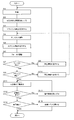
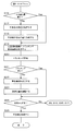
- FIGS. 6 and 7 represent an example of the operation of the optical image measurement device 1.
- 8 to 15 show examples of display screens.
- the control unit 210 displays a predetermined display screen (for example, the display screen 290 shown in FIG. 8) on the display unit 240 (touch panel monitor 11) in response to a predetermined operation (for example, power-on operation) (S2).
- the display screen 290 includes an adjustment screen 300 and an interference image display screen 400.
- the adjustment screen 300 is the same as that shown in FIG. 4 and is used for alignment adjustment and focus adjustment. Although illustration is omitted, an image captured by the fundus camera unit 1A is displayed on the adjustment screen 300. In FIGS. 8 to 12 and 15, information unnecessary for the following explanation is omitted from the information shown in FIG. 4.
- an interference image is displayed on the interference image display screen 400 (described later), the display state at this stage is, for example, a “sandstorm” state.
- the examiner operates the operation unit 250 to turn on the observation light source 101. Thereby, the anterior segment image of the eye E is displayed on the adjustment screen 300.
- the examiner operates the operation unit 250 (control lever) to move the fundus camera unit 1A to the subject side. At this time, the display image on the adjustment screen 300 is switched to a fundus observation image.
- the control unit 210 turns on the alignment light source 190a in response to a predetermined operation. Thereby, the alignment bright spot is projected onto the eye E, and the alignment bright spot 310 is displayed on the adjustment screen 300 as shown in FIG. 9 (S3). At this stage, since the alignment state is generally inappropriate, two alignment bright spots 310 are displayed outside the alignment scale 309.
- the examiner operates the control lever to adjust the position of the fundus camera unit 1A so as to move the two alignment bright spots 310 to the inside of the alignment scale 309 (S4).
- FIG. 10 shows an adjustment screen 300 in a state where the alignment adjustment is completed. Instead of manually adjusting the alignment as described above, it is also possible to execute auto alignment as described above.
- the control unit 210 turns on the LED 109a. Thereby, the split bright line is projected onto the eye E, and the split bright line 311 is displayed on the adjustment screen 300 as shown in FIG. 11 (S5). At this stage, since the focus state is generally inappropriate, the upper and lower split bright lines 311 are not aligned.
- the controller 210 performs autofocus in the manner described above (S6).
- the focus determination unit 232 determines whether or not the focus state by the autofocus is appropriate (S7).
- the control unit 210 causes the display unit 240 to display predetermined warning information (S8).
- This warning information informs, for example, that the autofocus has failed or that the examination is urged again.
- the warning information may be character string information or image information.
- An example of string information is the following message: "Autofocus failed. Pull the control lever again and try again.” The examiner who recognizes the failure of the autofocus from the warning information starts the examination again from the beginning. If “No” in step 7 occurs a predetermined number of times, the inspection may be terminated.
- the alignment determination unit 231 determines the suitability of the alignment state based on the position of the alignment bright spot 310 at this stage (S9).
- the control unit 210 causes the display unit 240 to display predetermined warning information (S10).
- This warning information informs, for example, that the alignment has been shifted or that the alignment is urged again.
- the warning information may be character string information or image information.
- An example of string information is the following message: “Match the alignment bright spots and put them in the scale.” The examiner who recognizes that the alignment state is not appropriate based on the warning information returns to step 4 and performs the alignment again.
- “No” in step 9 occurs a predetermined number of times, the inspection may be terminated or the inspection may be restarted from the beginning.
- the control unit 210 controls the OCT unit 150, the scanning unit 141, and the image forming unit 220 to automatically perform an interference image (tomographic image) of the fundus oculi Ef. Detection is performed (S11). Automatic detection can be performed by analyzing a detection signal obtained while moving the reference mirror 174, for example. Alternatively, automatic detection may be performed by actually forming an interference image and analyzing the luminance value of the interference image.
- the control unit 210 causes the display unit 240 to display predetermined warning information (S13).
- This warning information informs, for example, that no interference image is detected or that automatic detection is urged again.
- the warning information may be character string information or image information.
- An example of character string information is the following message: “Automatic interference image detection failed. Please try again.”
- the examiner who has recognized that the automatic detection has failed due to the warning information performs a predetermined operation (for example, touching the screen of the touch panel monitor 11) and instructs the automatic detection of the interference image again.
- “No” in step 12 occurs a predetermined number of times, the inspection may be terminated or the inspection may be restarted from the beginning.
- an interference image of the fundus oculi Ef is drawn somewhere in the frame.
- the interference image is displayed on the image display unit 401 of the interference image display screen 400.
- the interference image at this stage is displayed at a position where a part thereof protrudes from the interference image display screen 400 as shown in FIG.
- the image quality determination unit 234 determines whether or not the image quality of the detected interference image is appropriate (S14). When it is determined that the image quality is not appropriate (S14: No), the control unit 210 controls the rotation of the polarizing plate 175 to increase the image quality level (S15). At this time, it is desirable to control the polarizing plate 175 so that the image quality level is maximized.
- the image quality display unit 402 is an indicator that presents an evaluation value of image quality. Note that the evaluation value may be displayed as it is.
- the image position determination unit 233 determines whether the position of the interference image in the frame is appropriate (S16).
- the position of the interference image G is not appropriate. Determined. At this time, warning information indicating that may be displayed.
- the examiner designates a desirable display position of the interference image G within the frame (S17). This operation is performed, for example, by touching a desired position on the image display unit 401 (touch panel monitor 11). A preset position (for example, the center position of the image display unit 401) may be automatically designated.
- the control unit 210 obtains the displacement between the actual position of the interference image G (for example, the position of the macular center) and the designated position. Then, the control unit 210 controls the reference mirror 174 and the scanning unit 141 so as to cancel this displacement, that is, so that the interference image G is displayed at the designated position. Thereby, as shown in FIG. 14, the interference image G is displayed at a suitable position in the frame (S18).
- the displacement of the interference image G in the z direction can be canceled by adjusting the position of the reference mirror 174. Further, the displacement of the interference image G in the x direction and the y direction can be canceled by adjusting the scanning position of the signal light LS by the scanning unit 141.
- the control unit 210 displays the scanning region image 314 and the tracking region image 315 so as to overlap the fundus observation image (S19). Then, the control unit 210 controls the scanning unit 141 and the like to start tracking (S20).
- the scanning region image 314 represents a region in which the signal light LS is scanned, and is displayed according to a mode designated in advance.
- a scanning region image 314 shown in FIG. 15 corresponds to the above-described three-dimensional scan.
- the tracking area image 315 represents a characteristic part of the fundus oculi Ef to be tracked, and moves on the adjustment screen according to the tracking situation. Tracking is performed so that the tracking area image 315 is positioned at the center of the scanning area image 314.
- the tracking determination unit 235 determines whether the tracking state is appropriate (S21). This processing is performed by determining whether or not the tracking area image 315 is included in the scanning area image 314, for example. Note that it may be determined whether the tracking area image 315 is included in a predetermined area (area near the center) in the scanning area image 314.
- the control unit 210 causes the display unit 240 to display predetermined warning information (S22).
- This warning information informs that tracking cannot be suitably performed, for example.
- the warning information may be character string information or image information.
- An example of string information is the following message: “Tracking position is out of scanable range”.
- the examiner who recognizes that the tracking state is not appropriate based on the warning information operates the operation unit 250 (for example, a fixation position adjustment key), and fixes the eye E to be examined so that the tracking area image 315 enters the scanning area image 314.
- the viewing position is adjusted (S23).
- the tracking determination unit 235 determines whether the tracking state is appropriate.
- the image processing unit 230 When it is determined that the tracking state is appropriate (S21: Yes), or when the fixation position adjustment is completed (S23), the image processing unit 230 performs the alignment state, the focus state, and the position of the interference image in the frame. And the suitability of the image quality of the interference image is determined (S24).
- control unit 210 controls the OCT unit 150, the scanning unit 141, and the image forming unit 220 to form an interference image of the scanning region (S25). ).
- the control unit 210 controls the OCT unit 150, the scanning unit 141, and the image forming unit 220 to form an interference image of the scanning region (S25). ).
- a message indicating that measurement is possible may be displayed. In this case, the examiner who has seen the message presses the photographing switch to start measurement.
- the control unit 210 controls the fundus camera unit 1A to perform color photographing of the fundus oculi Ef.
- the acquired interference image and color fundus image are stored in the storage unit 212. This completes the inspection.
- the optical image measurement device 1 has a function of acquiring a tomographic image and a fundus image of the fundus (object to be measured).
- the fundus image is a two-dimensional image of the fundus on a plane substantially orthogonal to the traveling direction of the signal light LS with respect to the fundus.
- the optical image measurement device 1 has an alignment function, a focus function, and a tracking function.
- the alignment function is realized by alignment means including the alignment optical system 190A.
- the focus function is realized by focusing means including a focusing optical system.
- the tracking function is realized by tracking means including the control unit 210. The tracking can be performed based on a tomographic image or can be performed based on a fundus image.
- the configuration for acquiring a fundus image (configuration as a fundus camera) is an example of the “imaging unit” of the present invention.
- the optical image measurement device 1 determines whether each of the alignment state, the focus state, the position of the tomographic image in the frame, the image quality of the tomographic image, and the tracking state is appropriate, and it is determined that all these conditions are appropriate.
- the final tomographic image can be acquired. Note that the tomographic image used for determining the suitability of the conditions is acquired in advance, and it is desirable to use a simple scanning mode of the signal light LS (cross scanning in the above embodiment). Further, the distribution of scanning points (irradiation positions of the signal light LS) may not be so dense. On the other hand, the final tomographic image is a precise one used for diagnosis and the like, and it is desirable that the distribution of scanning points is dense (for example, a distribution that can generate a three-dimensional image).
- the above various conditions are automatically measured at an appropriate timing, so that the measurement timing is not missed.
- the optical image measurement device 1 can display warning information when any of the various conditions described above is not appropriate. Thereby, the examiner can recognize that the condition is not appropriate, and can take measures to make the condition appropriate.
- the suitability of each of the alignment state, focus state, tomographic image position in the frame, tomographic image quality, and tracking state is determined. This determination can be omitted.
- the optical image measurement device determines whether each of the alignment state, the focus state, and the position of the tomographic image in the frame is appropriate, and when all these conditions are determined to be appropriate, the final tomographic image is determined. Allows acquisition of images. Further, similarly to the above-described embodiment, it is possible to automatically perform measurement for obtaining a final tomographic image when it is determined that all conditions are appropriate.
- the essential condition determination process it may be configured to perform a tomographic image quality determination process or a tracking state determination process. These incidental conditions can be added as appropriate in consideration of the type (dynamics) of the object to be measured.
- It can be configured to prohibit the acquisition of a tomographic image of an object to be measured when it is determined that any of the above various conditions is not appropriate.
- the control unit 210 does not accept this instruction (ignore). Can be configured.
- the position of the reference mirror 174 is changed to change the optical path length difference between the optical path of the signal light LS and the optical path of the reference light LR.
- the method of changing the optical path length difference is limited to this. Is not to be done.
- the optical path length difference can be changed by moving the fundus camera unit 1A and the OCT unit 150 integrally with the eye E to change the optical path length of the signal light LS.
- the optical path length difference can be changed by moving the measured object in the depth direction (z direction).
- the computer program in the above embodiment can be stored in any recording medium that can be read by the drive device of the computer.
- this recording medium for example, an optical disk, a magneto-optical disk (CD-ROM / DVD-RAM / DVD-ROM / MO, etc.), a magnetic storage medium (hard disk / floppy (registered trademark) disk / ZIP, etc.), etc. are used. Is possible. It can also be stored in a storage device such as a hard disk drive or memory. Furthermore, this program can be transmitted and received through a network such as the Internet or a LAN.
Landscapes
- Physics & Mathematics (AREA)
- General Physics & Mathematics (AREA)
- Health & Medical Sciences (AREA)
- Engineering & Computer Science (AREA)
- Life Sciences & Earth Sciences (AREA)
- General Health & Medical Sciences (AREA)
- Nuclear Medicine, Radiotherapy & Molecular Imaging (AREA)
- Radiology & Medical Imaging (AREA)
- Optics & Photonics (AREA)
- Biomedical Technology (AREA)
- Surgery (AREA)
- Signal Processing (AREA)
- Biophysics (AREA)
- Ophthalmology & Optometry (AREA)
- Human Computer Interaction (AREA)
- Heart & Thoracic Surgery (AREA)
- Medical Informatics (AREA)
- Molecular Biology (AREA)
- Automation & Control Theory (AREA)
- Animal Behavior & Ethology (AREA)
- Public Health (AREA)
- Veterinary Medicine (AREA)
- Chemical & Material Sciences (AREA)
- Analytical Chemistry (AREA)
- Biochemistry (AREA)
- Immunology (AREA)
- Pathology (AREA)
- Eye Examination Apparatus (AREA)
- Investigating Or Analysing Materials By Optical Means (AREA)
Priority Applications (3)
| Application Number | Priority Date | Filing Date | Title |
|---|---|---|---|
| US13/147,536 US8970847B2 (en) | 2009-02-03 | 2009-12-09 | Optical image measuring device |
| EP09839611.2A EP2395343B1 (en) | 2009-02-03 | 2009-12-09 | Optical image measuring device |
| ES09839611.2T ES2689346T3 (es) | 2009-02-03 | 2009-12-09 | Dispositivo óptico de medición de imágenes |
Applications Claiming Priority (2)
| Application Number | Priority Date | Filing Date | Title |
|---|---|---|---|
| JP2009022622A JP5404078B2 (ja) | 2009-02-03 | 2009-02-03 | 光画像計測装置 |
| JP2009-022622 | 2009-02-03 |
Publications (1)
| Publication Number | Publication Date |
|---|---|
| WO2010089833A1 true WO2010089833A1 (ja) | 2010-08-12 |
Family
ID=42541759
Family Applications (1)
| Application Number | Title | Priority Date | Filing Date |
|---|---|---|---|
| PCT/JP2009/006711 WO2010089833A1 (ja) | 2009-02-03 | 2009-12-09 | 光画像計測装置 |
Country Status (5)
| Country | Link |
|---|---|
| US (1) | US8970847B2 (zh) |
| EP (1) | EP2395343B1 (zh) |
| JP (1) | JP5404078B2 (zh) |
| ES (1) | ES2689346T3 (zh) |
| WO (1) | WO2010089833A1 (zh) |
Cited By (11)
| Publication number | Priority date | Publication date | Assignee | Title |
|---|---|---|---|---|
| WO2012086134A1 (ja) * | 2010-12-21 | 2012-06-28 | パナソニック株式会社 | 光断層画像取得装置 |
| JP2012161545A (ja) * | 2011-02-09 | 2012-08-30 | Panasonic Corp | 光断層画像取得装置 |
| CN102727174A (zh) * | 2011-03-31 | 2012-10-17 | 佳能株式会社 | 眼底检查设备 |
| CN103458774A (zh) * | 2011-03-31 | 2013-12-18 | 佳能株式会社 | 医疗系统 |
| US20140063450A1 (en) * | 2012-08-30 | 2014-03-06 | Canon Kabushiki Kaisha | Imaging apparatus and imaging method |
| CN103799971A (zh) * | 2012-11-09 | 2014-05-21 | 佳能株式会社 | 眼科装置及眼科方法 |
| JP2014140542A (ja) * | 2013-01-24 | 2014-08-07 | Topcon Corp | 眼科観察装置 |
| JP2015091552A (ja) * | 2015-02-19 | 2015-05-14 | キヤノン株式会社 | 光干渉断層撮影装置及び画像処理方法 |
| US9221076B2 (en) | 2010-11-02 | 2015-12-29 | Ut-Battelle, Llc | Composition for forming an optically transparent, superhydrophobic coating |
| JP2017124204A (ja) * | 2017-03-06 | 2017-07-20 | 株式会社トプコン | 眼科観察装置 |
| US9883795B2 (en) | 2011-03-31 | 2018-02-06 | Canon Kabushiki Kaisha | Optical coherence tomography apparatus, image processing apparatus, image processing method, and storage medium of program |
Families Citing this family (41)
| Publication number | Priority date | Publication date | Assignee | Title |
|---|---|---|---|---|
| JP5415902B2 (ja) * | 2009-10-27 | 2014-02-12 | 株式会社トプコン | 眼科観察装置 |
| JP2012002597A (ja) * | 2010-06-15 | 2012-01-05 | Fujifilm Corp | 光断層画像化装置及び光断層画像化方法 |
| EP2449957B1 (en) | 2010-11-05 | 2015-03-25 | Nidek Co., Ltd. | Control method of a fundus examination apparatus |
| JP5727198B2 (ja) * | 2010-11-05 | 2015-06-03 | 株式会社ニデック | 眼科装置 |
| JP5220155B2 (ja) * | 2011-03-31 | 2013-06-26 | キヤノン株式会社 | 眼科装置および眼科装置の制御方法 |
| JP5926533B2 (ja) * | 2011-10-27 | 2016-05-25 | キヤノン株式会社 | 眼科装置 |
| US8960909B2 (en) * | 2012-01-20 | 2015-02-24 | Canon Kabushiki Kaisha | Control apparatus and control method |
| ITPI20120009A1 (it) * | 2012-01-24 | 2013-07-25 | Visia Imaging S R L | "un metodo per ridurre il tempo della misura a scansione della lunghezza assiale oculare e dispositivo per attuare tale metodo" |
| US9674407B2 (en) * | 2012-02-14 | 2017-06-06 | Honeywell International Inc. | System and method for interactive image capture for a device having a camera |
| EP2829220B1 (en) * | 2012-03-21 | 2019-08-07 | Utsunomiya University | Device for generating three-dimensional retina image |
| EP2644086B1 (en) | 2012-03-30 | 2015-11-04 | Canon Kabushiki Kaisha | Fundus inspection apparatus |
| JP6007549B2 (ja) | 2012-03-30 | 2016-10-12 | 株式会社ニデック | 眼底撮影装置 |
| JP6098061B2 (ja) * | 2012-07-27 | 2017-03-22 | 株式会社ニデック | 眼底撮影装置 |
| JP6057620B2 (ja) * | 2012-08-30 | 2017-01-11 | キヤノン株式会社 | 光断層画像撮像装置、画像処理装置及び光断層画像の表示方法 |
| JP2014045868A (ja) * | 2012-08-30 | 2014-03-17 | Canon Inc | インタラクティブ制御装置 |
| JP2014094162A (ja) * | 2012-11-09 | 2014-05-22 | Canon Inc | 眼科撮像装置 |
| WO2014112393A1 (ja) * | 2013-01-21 | 2014-07-24 | パナソニック株式会社 | 測定装置および測定方法 |
| JP6160807B2 (ja) * | 2013-01-23 | 2017-07-12 | 株式会社ニデック | 眼科撮影装置及び眼科撮影プログラム |
| US9295386B2 (en) * | 2013-04-03 | 2016-03-29 | Kabushiki Kaisha Topcon | Ophthalmologic apparatus |
| RU2634998C2 (ru) * | 2013-05-29 | 2017-11-08 | Уэйвлайт Гмбх | Аппарат для оптической когерентной томографии (окт) глаза и способ оптической когерентной томографии (окт) глаза |
| JP5602912B2 (ja) * | 2013-06-06 | 2014-10-08 | キヤノン株式会社 | 眼科装置 |
| JP6367530B2 (ja) * | 2013-07-11 | 2018-08-01 | 株式会社トーメーコーポレーション | 断層画像撮影装置及び断層画像の画像生成制御方法 |
| EP2865323B1 (en) * | 2013-10-23 | 2022-02-16 | Canon Kabushiki Kaisha | Retinal movement tracking in optical coherence tomography |
| JP6220248B2 (ja) * | 2013-11-29 | 2017-10-25 | キヤノン株式会社 | 眼科装置及び制御方法 |
| JP5905041B2 (ja) * | 2014-02-06 | 2016-04-20 | キヤノン株式会社 | 撮像装置、制御装置及び制御方法 |
| JP6354979B2 (ja) * | 2014-03-31 | 2018-07-11 | 株式会社ニデック | 眼底撮影装置 |
| JP2016041221A (ja) | 2014-08-19 | 2016-03-31 | 株式会社トプコン | 眼科撮影装置およびその制御方法 |
| JP6498398B2 (ja) | 2014-08-27 | 2019-04-10 | 株式会社トプコン | 眼科装置 |
| JP6566541B2 (ja) | 2014-11-26 | 2019-08-28 | 株式会社トプコン | 眼科装置 |
| US10362984B2 (en) | 2015-01-27 | 2019-07-30 | Healthy.Io Ltd | Measuring and monitoring skin feature colors, form and size |
| TWI584778B (zh) * | 2016-02-04 | 2017-06-01 | 慈濟學校財團法人慈濟大學 | 光學檢測裝置及其系統 |
| US10832051B1 (en) * | 2016-06-13 | 2020-11-10 | Facebook Technologies, Llc | Eye tracking using optical coherence methods |
| JP6570552B2 (ja) * | 2017-01-06 | 2019-09-04 | キヤノン株式会社 | インタラクティブ制御装置 |
| JP6922358B2 (ja) * | 2017-04-06 | 2021-08-18 | 株式会社ニデック | 生体観察システムおよび生体観察制御プログラム |
| US10726547B2 (en) * | 2017-05-18 | 2020-07-28 | Welch Allyn, Inc. | Fundus image capturing |
| DK3668372T3 (da) | 2017-08-14 | 2022-02-14 | Optos Plc | Oftalmisk indretning |
| CN111163684B (zh) | 2017-08-14 | 2022-07-22 | 奥普托斯股份有限公司 | 眼科设备 |
| JP7106320B2 (ja) * | 2018-03-27 | 2022-07-26 | 株式会社トプコン | 眼科装置、及び眼科装置の制御方法 |
| US10963046B1 (en) | 2018-05-17 | 2021-03-30 | Facebook Technologies, Llc | Drift corrected eye tracking |
| JP7211497B2 (ja) * | 2019-05-16 | 2023-01-24 | 日本電気株式会社 | 光干渉断層撮像装置、撮像方法、及び、撮像プログラム |
| JP6812514B2 (ja) * | 2019-08-05 | 2021-01-13 | キヤノン株式会社 | 撮像システム、及び、その制御方法 |
Citations (17)
| Publication number | Priority date | Publication date | Assignee | Title |
|---|---|---|---|---|
| JPH09276232A (ja) | 1996-04-12 | 1997-10-28 | Nikon Corp | 眼底カメラ |
| JPH114808A (ja) | 1997-04-24 | 1999-01-12 | Topcon Corp | 眼底カメラ |
| JPH11325849A (ja) | 1998-03-30 | 1999-11-26 | Carl Zeiss Jena Gmbh | スペクトル干渉に基づく光学・トモグラフィ―および光学表面プロファイル測定装置 |
| JP2002139421A (ja) | 2000-11-01 | 2002-05-17 | Fuji Photo Film Co Ltd | 光断層画像取得装置 |
| JP2006153838A (ja) | 2004-11-08 | 2006-06-15 | Topcon Corp | 光画像計測装置及び光画像計測方法 |
| JP2007024677A (ja) | 2005-07-15 | 2007-02-01 | Sun Tec Kk | 光断層画像表示システム |
| JP2007252693A (ja) * | 2006-03-24 | 2007-10-04 | Topcon Corp | 眼底観察装置 |
| JP2008000342A (ja) | 2006-06-22 | 2008-01-10 | Topcon Corp | 眼科装置 |
| JP2008000343A (ja) | 2006-06-22 | 2008-01-10 | Topcon Corp | 眼科装置 |
| JP2008005987A (ja) * | 2006-06-28 | 2008-01-17 | Topcon Corp | 眼底観察装置及びそれを制御するプログラム |
| JP2008013989A (ja) | 2006-07-05 | 2008-01-24 | Nichibei Co Ltd | 縦型ブラインド |
| JP2008154941A (ja) * | 2006-12-26 | 2008-07-10 | Topcon Corp | 光画像計測装置及び光画像計測装置を制御するプログラム |
| JP2008154725A (ja) | 2006-12-22 | 2008-07-10 | Topcon Corp | 眼科装置 |
| JP2008154726A (ja) | 2006-12-22 | 2008-07-10 | Topcon Corp | 眼科装置 |
| JP2008154939A (ja) * | 2006-12-26 | 2008-07-10 | Topcon Corp | 光画像計測装置及び光画像計測装置を制御するプログラム |
| JP2008237237A (ja) * | 2007-03-23 | 2008-10-09 | Topcon Corp | 眼底観察装置、眼科画像表示装置及びプログラム |
| JP2008289579A (ja) | 2007-05-23 | 2008-12-04 | Topcon Corp | 眼底観察装置及びそれを制御するプログラム |
Family Cites Families (8)
| Publication number | Priority date | Publication date | Assignee | Title |
|---|---|---|---|---|
| JPH07289523A (ja) * | 1995-04-21 | 1995-11-07 | Topcon Corp | 非接触式眼圧計 |
| JP3927695B2 (ja) | 1998-07-16 | 2007-06-13 | キヤノン株式会社 | 眼科装置 |
| JP4546209B2 (ja) * | 2004-09-30 | 2010-09-15 | 株式会社ニデック | 眼科装置 |
| EP1869398B1 (en) * | 2005-03-17 | 2012-08-22 | The Board Of Trustees Of The Leland Stanford Junior University | Apparatus and method for frequency-domain optical coherence tomography |
| KR20080066705A (ko) * | 2005-09-29 | 2008-07-16 | 더 제너럴 하스피탈 코포레이션 | 점진적으로 증가하는 분해능을 이용하여 하나 이상의 생물학적 샘플을 관찰 및 분석하기 위한 방법 및 장치 |
| JP2007252475A (ja) * | 2006-03-22 | 2007-10-04 | Fujifilm Corp | 光断層画像化装置および光断層画像の画質調整方法 |
| JP4822969B2 (ja) | 2006-07-27 | 2011-11-24 | 株式会社ニデック | 眼科撮影装置 |
| US8223143B2 (en) | 2006-10-27 | 2012-07-17 | Carl Zeiss Meditec, Inc. | User interface for efficiently displaying relevant OCT imaging data |
-
2009
- 2009-02-03 JP JP2009022622A patent/JP5404078B2/ja active Active
- 2009-12-09 US US13/147,536 patent/US8970847B2/en active Active
- 2009-12-09 WO PCT/JP2009/006711 patent/WO2010089833A1/ja active Application Filing
- 2009-12-09 ES ES09839611.2T patent/ES2689346T3/es active Active
- 2009-12-09 EP EP09839611.2A patent/EP2395343B1/en active Active
Patent Citations (17)
| Publication number | Priority date | Publication date | Assignee | Title |
|---|---|---|---|---|
| JPH09276232A (ja) | 1996-04-12 | 1997-10-28 | Nikon Corp | 眼底カメラ |
| JPH114808A (ja) | 1997-04-24 | 1999-01-12 | Topcon Corp | 眼底カメラ |
| JPH11325849A (ja) | 1998-03-30 | 1999-11-26 | Carl Zeiss Jena Gmbh | スペクトル干渉に基づく光学・トモグラフィ―および光学表面プロファイル測定装置 |
| JP2002139421A (ja) | 2000-11-01 | 2002-05-17 | Fuji Photo Film Co Ltd | 光断層画像取得装置 |
| JP2006153838A (ja) | 2004-11-08 | 2006-06-15 | Topcon Corp | 光画像計測装置及び光画像計測方法 |
| JP2007024677A (ja) | 2005-07-15 | 2007-02-01 | Sun Tec Kk | 光断層画像表示システム |
| JP2007252693A (ja) * | 2006-03-24 | 2007-10-04 | Topcon Corp | 眼底観察装置 |
| JP2008000343A (ja) | 2006-06-22 | 2008-01-10 | Topcon Corp | 眼科装置 |
| JP2008000342A (ja) | 2006-06-22 | 2008-01-10 | Topcon Corp | 眼科装置 |
| JP2008005987A (ja) * | 2006-06-28 | 2008-01-17 | Topcon Corp | 眼底観察装置及びそれを制御するプログラム |
| JP2008013989A (ja) | 2006-07-05 | 2008-01-24 | Nichibei Co Ltd | 縦型ブラインド |
| JP2008154725A (ja) | 2006-12-22 | 2008-07-10 | Topcon Corp | 眼科装置 |
| JP2008154726A (ja) | 2006-12-22 | 2008-07-10 | Topcon Corp | 眼科装置 |
| JP2008154941A (ja) * | 2006-12-26 | 2008-07-10 | Topcon Corp | 光画像計測装置及び光画像計測装置を制御するプログラム |
| JP2008154939A (ja) * | 2006-12-26 | 2008-07-10 | Topcon Corp | 光画像計測装置及び光画像計測装置を制御するプログラム |
| JP2008237237A (ja) * | 2007-03-23 | 2008-10-09 | Topcon Corp | 眼底観察装置、眼科画像表示装置及びプログラム |
| JP2008289579A (ja) | 2007-05-23 | 2008-12-04 | Topcon Corp | 眼底観察装置及びそれを制御するプログラム |
Non-Patent Citations (1)
| Title |
|---|
| See also references of EP2395343A4 * |
Cited By (16)
| Publication number | Priority date | Publication date | Assignee | Title |
|---|---|---|---|---|
| US9221076B2 (en) | 2010-11-02 | 2015-12-29 | Ut-Battelle, Llc | Composition for forming an optically transparent, superhydrophobic coating |
| WO2012086134A1 (ja) * | 2010-12-21 | 2012-06-28 | パナソニック株式会社 | 光断層画像取得装置 |
| JP2012161545A (ja) * | 2011-02-09 | 2012-08-30 | Panasonic Corp | 光断層画像取得装置 |
| CN102727174A (zh) * | 2011-03-31 | 2012-10-17 | 佳能株式会社 | 眼底检查设备 |
| CN103458774A (zh) * | 2011-03-31 | 2013-12-18 | 佳能株式会社 | 医疗系统 |
| US9883795B2 (en) | 2011-03-31 | 2018-02-06 | Canon Kabushiki Kaisha | Optical coherence tomography apparatus, image processing apparatus, image processing method, and storage medium of program |
| US9538916B2 (en) | 2011-03-31 | 2017-01-10 | Canon Kabushiki Kaisha | Fundus inspection apparatus |
| US9326679B2 (en) | 2011-03-31 | 2016-05-03 | Canon Kabushiki Kaisha | Medical system |
| CN103458774B (zh) * | 2011-03-31 | 2016-03-30 | 佳能株式会社 | 医疗系统 |
| CN102727174B (zh) * | 2011-03-31 | 2015-09-30 | 佳能株式会社 | 眼底检查设备 |
| US20140063450A1 (en) * | 2012-08-30 | 2014-03-06 | Canon Kabushiki Kaisha | Imaging apparatus and imaging method |
| US9078596B2 (en) * | 2012-08-30 | 2015-07-14 | Canon Kabushiki Kaisha | Imaging apparatus and imaging method |
| CN103799971A (zh) * | 2012-11-09 | 2014-05-21 | 佳能株式会社 | 眼科装置及眼科方法 |
| JP2014140542A (ja) * | 2013-01-24 | 2014-08-07 | Topcon Corp | 眼科観察装置 |
| JP2015091552A (ja) * | 2015-02-19 | 2015-05-14 | キヤノン株式会社 | 光干渉断層撮影装置及び画像処理方法 |
| JP2017124204A (ja) * | 2017-03-06 | 2017-07-20 | 株式会社トプコン | 眼科観察装置 |
Also Published As
| Publication number | Publication date |
|---|---|
| JP5404078B2 (ja) | 2014-01-29 |
| US8970847B2 (en) | 2015-03-03 |
| US20110286003A1 (en) | 2011-11-24 |
| EP2395343B1 (en) | 2018-09-05 |
| EP2395343A1 (en) | 2011-12-14 |
| ES2689346T3 (es) | 2018-11-13 |
| JP2010181172A (ja) | 2010-08-19 |
| EP2395343A4 (en) | 2012-08-08 |
Similar Documents
| Publication | Publication Date | Title |
|---|---|---|
| JP5404078B2 (ja) | 光画像計測装置 | |
| JP5085086B2 (ja) | 眼底観察装置、眼底画像表示装置及びプログラム | |
| JP5324839B2 (ja) | 光画像計測装置 | |
| JP4864515B2 (ja) | 眼底観察装置 | |
| JP6045895B2 (ja) | 眼科観察装置 | |
| WO2016027589A1 (ja) | 眼科撮影装置およびその制御方法 | |
| JP6566541B2 (ja) | 眼科装置 | |
| JP2007275375A (ja) | 眼科装置 | |
| JP2008005987A (ja) | 眼底観察装置及びそれを制御するプログラム | |
| JP6498398B2 (ja) | 眼科装置 | |
| JP6411728B2 (ja) | 眼科観察装置 | |
| JP5584345B2 (ja) | 光画像計測装置及び撮影装置 | |
| US10045691B2 (en) | Ophthalmologic observation apparatus using optical coherence tomography | |
| WO2013085042A1 (ja) | 眼底観察装置 | |
| JP6407631B2 (ja) | 眼科装置 | |
| JP6108845B2 (ja) | 眼科観察装置 | |
| JP6159454B2 (ja) | 眼科観察装置 | |
| JP5144579B2 (ja) | 眼科観察装置 | |
| JP5919175B2 (ja) | 光画像計測装置 | |
| JP6311045B2 (ja) | 眼科観察装置 | |
| JP2018023818A (ja) | 眼科観察装置 | |
| JP2012223428A (ja) | 眼科装置 | |
| JP2018023816A (ja) | 眼科観察装置 | |
| JP6404431B2 (ja) | 眼科観察装置 | |
| JP2019135005A (ja) | 眼科撮影装置 |
Legal Events
| Date | Code | Title | Description |
|---|---|---|---|
| 121 | Ep: the epo has been informed by wipo that ep was designated in this application |
Ref document number: 09839611 Country of ref document: EP Kind code of ref document: A1 |
|
| WWE | Wipo information: entry into national phase |
Ref document number: 2009839611 Country of ref document: EP |
|
| WWE | Wipo information: entry into national phase |
Ref document number: 13147536 Country of ref document: US |
|
| NENP | Non-entry into the national phase |
Ref country code: DE |