WO2010050242A1 - サンドイッチパネルおよびサンドイッチパネル用芯材の成形方法、ならびにサンドイッチパネルの成形方法 - Google Patents
サンドイッチパネルおよびサンドイッチパネル用芯材の成形方法、ならびにサンドイッチパネルの成形方法 Download PDFInfo
- Publication number
- WO2010050242A1 WO2010050242A1 PCT/JP2009/005807 JP2009005807W WO2010050242A1 WO 2010050242 A1 WO2010050242 A1 WO 2010050242A1 JP 2009005807 W JP2009005807 W JP 2009005807W WO 2010050242 A1 WO2010050242 A1 WO 2010050242A1
- Authority
- WO
- WIPO (PCT)
- Prior art keywords
- core material
- thermoplastic resin
- pair
- sandwich panel
- sheet
- Prior art date
Links
- 239000011162 core material Substances 0.000 title claims abstract description 290
- 238000000034 method Methods 0.000 title claims description 76
- 239000000463 material Substances 0.000 claims abstract description 196
- 229920005992 thermoplastic resin Polymers 0.000 claims abstract description 149
- 229920005989 resin Polymers 0.000 claims abstract description 120
- 239000011347 resin Substances 0.000 claims abstract description 120
- 239000007787 solid Substances 0.000 claims abstract description 10
- 238000000465 moulding Methods 0.000 claims description 50
- 238000005187 foaming Methods 0.000 claims description 41
- 238000001125 extrusion Methods 0.000 claims description 28
- 239000011800 void material Substances 0.000 claims description 25
- 239000004088 foaming agent Substances 0.000 claims description 19
- 230000002093 peripheral effect Effects 0.000 claims description 19
- 238000003466 welding Methods 0.000 claims description 16
- 238000003825 pressing Methods 0.000 claims description 12
- 238000007493 shaping process Methods 0.000 claims description 9
- 238000009413 insulation Methods 0.000 claims description 7
- 238000004519 manufacturing process Methods 0.000 claims description 6
- 238000007373 indentation Methods 0.000 claims description 5
- 238000003303 reheating Methods 0.000 claims description 4
- 238000004898 kneading Methods 0.000 claims description 2
- 230000035515 penetration Effects 0.000 claims description 2
- 238000005452 bending Methods 0.000 abstract description 17
- 230000006835 compression Effects 0.000 abstract description 12
- 238000007906 compression Methods 0.000 abstract description 12
- 239000006260 foam Substances 0.000 abstract description 11
- 238000010008 shearing Methods 0.000 abstract 1
- 239000013585 weight reducing agent Substances 0.000 description 20
- 230000008569 process Effects 0.000 description 18
- 230000015572 biosynthetic process Effects 0.000 description 17
- -1 polypropylene Polymers 0.000 description 15
- 239000004743 Polypropylene Substances 0.000 description 12
- 238000012986 modification Methods 0.000 description 11
- 230000004048 modification Effects 0.000 description 11
- 229920001155 polypropylene Polymers 0.000 description 11
- 239000010410 layer Substances 0.000 description 10
- 238000012360 testing method Methods 0.000 description 10
- 230000007423 decrease Effects 0.000 description 7
- 238000001746 injection moulding Methods 0.000 description 7
- 229910052751 metal Inorganic materials 0.000 description 7
- 239000002184 metal Substances 0.000 description 7
- 239000000203 mixture Substances 0.000 description 7
- CURLTUGMZLYLDI-UHFFFAOYSA-N Carbon dioxide Chemical compound O=C=O CURLTUGMZLYLDI-UHFFFAOYSA-N 0.000 description 6
- VYPSYNLAJGMNEJ-UHFFFAOYSA-N Silicium dioxide Chemical compound O=[Si]=O VYPSYNLAJGMNEJ-UHFFFAOYSA-N 0.000 description 6
- 238000006243 chemical reaction Methods 0.000 description 6
- 230000011218 segmentation Effects 0.000 description 6
- IJGRMHOSHXDMSA-UHFFFAOYSA-N Atomic nitrogen Chemical compound N#N IJGRMHOSHXDMSA-UHFFFAOYSA-N 0.000 description 5
- 229920001577 copolymer Polymers 0.000 description 5
- 238000009826 distribution Methods 0.000 description 5
- 239000000835 fiber Substances 0.000 description 5
- 229920005672 polyolefin resin Polymers 0.000 description 5
- VTYYLEPIZMXCLO-UHFFFAOYSA-L Calcium carbonate Chemical compound [Ca+2].[O-]C([O-])=O VTYYLEPIZMXCLO-UHFFFAOYSA-L 0.000 description 4
- 239000000654 additive Substances 0.000 description 4
- 230000000996 additive effect Effects 0.000 description 4
- 239000011324 bead Substances 0.000 description 4
- 239000000446 fuel Substances 0.000 description 4
- 239000000454 talc Substances 0.000 description 4
- 229910052623 talc Inorganic materials 0.000 description 4
- 229920000049 Carbon (fiber) Polymers 0.000 description 3
- YMWUJEATGCHHMB-UHFFFAOYSA-N Dichloromethane Chemical compound ClCCl YMWUJEATGCHHMB-UHFFFAOYSA-N 0.000 description 3
- 229920000297 Rayon Polymers 0.000 description 3
- PPBRXRYQALVLMV-UHFFFAOYSA-N Styrene Natural products C=CC1=CC=CC=C1 PPBRXRYQALVLMV-UHFFFAOYSA-N 0.000 description 3
- 238000010521 absorption reaction Methods 0.000 description 3
- 239000000853 adhesive Substances 0.000 description 3
- 230000001070 adhesive effect Effects 0.000 description 3
- 238000000071 blow moulding Methods 0.000 description 3
- 229910002092 carbon dioxide Inorganic materials 0.000 description 3
- 239000001569 carbon dioxide Substances 0.000 description 3
- 239000004917 carbon fiber Substances 0.000 description 3
- 239000012530 fluid Substances 0.000 description 3
- 239000003365 glass fiber Substances 0.000 description 3
- 238000005259 measurement Methods 0.000 description 3
- 239000000155 melt Substances 0.000 description 3
- VNWKTOKETHGBQD-UHFFFAOYSA-N methane Chemical compound C VNWKTOKETHGBQD-UHFFFAOYSA-N 0.000 description 3
- 239000010445 mica Substances 0.000 description 3
- 229910052618 mica group Inorganic materials 0.000 description 3
- VLKZOEOYAKHREP-UHFFFAOYSA-N n-Hexane Chemical compound CCCCCC VLKZOEOYAKHREP-UHFFFAOYSA-N 0.000 description 3
- OFBQJSOFQDEBGM-UHFFFAOYSA-N n-pentane Natural products CCCCC OFBQJSOFQDEBGM-UHFFFAOYSA-N 0.000 description 3
- 239000004745 nonwoven fabric Substances 0.000 description 3
- 229920001384 propylene homopolymer Polymers 0.000 description 3
- 239000000377 silicon dioxide Substances 0.000 description 3
- 239000002344 surface layer Substances 0.000 description 3
- 229920002994 synthetic fiber Polymers 0.000 description 3
- 229920002725 thermoplastic elastomer Polymers 0.000 description 3
- XLYOFNOQVPJJNP-UHFFFAOYSA-N water Substances O XLYOFNOQVPJJNP-UHFFFAOYSA-N 0.000 description 3
- 229910001868 water Inorganic materials 0.000 description 3
- SAAZSCOLNCGLKL-UHFFFAOYSA-N 2-methylbuta-1,3-diene;pent-1-ene Chemical compound CCCC=C.CC(=C)C=C SAAZSCOLNCGLKL-UHFFFAOYSA-N 0.000 description 2
- JMMZCWZIJXAGKW-UHFFFAOYSA-N 2-methylpent-2-ene Chemical compound CCC=C(C)C JMMZCWZIJXAGKW-UHFFFAOYSA-N 0.000 description 2
- 239000004952 Polyamide Substances 0.000 description 2
- 239000004793 Polystyrene Substances 0.000 description 2
- NIXOWILDQLNWCW-UHFFFAOYSA-N acrylic acid group Chemical group C(C=C)(=O)O NIXOWILDQLNWCW-UHFFFAOYSA-N 0.000 description 2
- 229920000122 acrylonitrile butadiene styrene Polymers 0.000 description 2
- 229920001893 acrylonitrile styrene Polymers 0.000 description 2
- 150000001336 alkenes Chemical class 0.000 description 2
- 239000004566 building material Substances 0.000 description 2
- 229910000019 calcium carbonate Inorganic materials 0.000 description 2
- 239000003795 chemical substances by application Substances 0.000 description 2
- 239000003086 colorant Substances 0.000 description 2
- 238000000748 compression moulding Methods 0.000 description 2
- 239000002537 cosmetic Substances 0.000 description 2
- 229920005676 ethylene-propylene block copolymer Polymers 0.000 description 2
- 239000004744 fabric Substances 0.000 description 2
- 239000003063 flame retardant Substances 0.000 description 2
- 230000004927 fusion Effects 0.000 description 2
- 229920001903 high density polyethylene Polymers 0.000 description 2
- 229920005669 high impact polystyrene Polymers 0.000 description 2
- 239000004700 high-density polyethylene Substances 0.000 description 2
- 239000004797 high-impact polystyrene Substances 0.000 description 2
- 229920001519 homopolymer Polymers 0.000 description 2
- 238000002347 injection Methods 0.000 description 2
- 239000007924 injection Substances 0.000 description 2
- 239000011256 inorganic filler Substances 0.000 description 2
- 229910003475 inorganic filler Inorganic materials 0.000 description 2
- 229910052757 nitrogen Inorganic materials 0.000 description 2
- 229920002647 polyamide Polymers 0.000 description 2
- 229920000728 polyester Polymers 0.000 description 2
- 229920000098 polyolefin Polymers 0.000 description 2
- 229920002223 polystyrene Polymers 0.000 description 2
- 229920002635 polyurethane Polymers 0.000 description 2
- 239000004814 polyurethane Substances 0.000 description 2
- SCUZVMOVTVSBLE-UHFFFAOYSA-N prop-2-enenitrile;styrene Chemical compound C=CC#N.C=CC1=CC=CC=C1 SCUZVMOVTVSBLE-UHFFFAOYSA-N 0.000 description 2
- 239000002964 rayon Substances 0.000 description 2
- 239000003381 stabilizer Substances 0.000 description 2
- 150000003440 styrenes Chemical class 0.000 description 2
- 239000000126 substance Substances 0.000 description 2
- 239000012209 synthetic fiber Substances 0.000 description 2
- 229920001187 thermosetting polymer Polymers 0.000 description 2
- 230000009466 transformation Effects 0.000 description 2
- 238000007666 vacuum forming Methods 0.000 description 2
- SCYULBFZEHDVBN-UHFFFAOYSA-N 1,1-Dichloroethane Chemical compound CC(Cl)Cl SCYULBFZEHDVBN-UHFFFAOYSA-N 0.000 description 1
- RNFJDJUURJAICM-UHFFFAOYSA-N 2,2,4,4,6,6-hexaphenoxy-1,3,5-triaza-2$l^{5},4$l^{5},6$l^{5}-triphosphacyclohexa-1,3,5-triene Chemical compound N=1P(OC=2C=CC=CC=2)(OC=2C=CC=CC=2)=NP(OC=2C=CC=CC=2)(OC=2C=CC=CC=2)=NP=1(OC=1C=CC=CC=1)OC1=CC=CC=C1 RNFJDJUURJAICM-UHFFFAOYSA-N 0.000 description 1
- QTBSBXVTEAMEQO-UHFFFAOYSA-M Acetate Chemical compound CC([O-])=O QTBSBXVTEAMEQO-UHFFFAOYSA-M 0.000 description 1
- NLHHRLWOUZZQLW-UHFFFAOYSA-N Acrylonitrile Chemical compound C=CC#N NLHHRLWOUZZQLW-UHFFFAOYSA-N 0.000 description 1
- 244000025254 Cannabis sativa Species 0.000 description 1
- 235000012766 Cannabis sativa ssp. sativa var. sativa Nutrition 0.000 description 1
- 235000012765 Cannabis sativa ssp. sativa var. spontanea Nutrition 0.000 description 1
- 229920000742 Cotton Polymers 0.000 description 1
- 241000479907 Devia <beetle> Species 0.000 description 1
- 229920000877 Melamine resin Polymers 0.000 description 1
- 239000004640 Melamine resin Substances 0.000 description 1
- 229930182556 Polyacetal Natural products 0.000 description 1
- 239000004697 Polyetherimide Substances 0.000 description 1
- 239000004698 Polyethylene Substances 0.000 description 1
- 239000004642 Polyimide Substances 0.000 description 1
- 239000004721 Polyphenylene oxide Substances 0.000 description 1
- 229920002978 Vinylon Polymers 0.000 description 1
- XECAHXYUAAWDEL-UHFFFAOYSA-N acrylonitrile butadiene styrene Chemical compound C=CC=C.C=CC#N.C=CC1=CC=CC=C1 XECAHXYUAAWDEL-UHFFFAOYSA-N 0.000 description 1
- 239000004676 acrylonitrile butadiene styrene Substances 0.000 description 1
- 230000002411 adverse Effects 0.000 description 1
- 239000003570 air Substances 0.000 description 1
- 229920006127 amorphous resin Polymers 0.000 description 1
- 239000002216 antistatic agent Substances 0.000 description 1
- 238000013459 approach Methods 0.000 description 1
- 229920001400 block copolymer Polymers 0.000 description 1
- MTAZNLWOLGHBHU-UHFFFAOYSA-N butadiene-styrene rubber Chemical class C=CC=C.C=CC1=CC=CC=C1 MTAZNLWOLGHBHU-UHFFFAOYSA-N 0.000 description 1
- 239000001273 butane Substances 0.000 description 1
- 235000009120 camo Nutrition 0.000 description 1
- 230000008859 change Effects 0.000 description 1
- 235000005607 chanvre indien Nutrition 0.000 description 1
- 230000000295 complement effect Effects 0.000 description 1
- 238000012790 confirmation Methods 0.000 description 1
- 239000000470 constituent Substances 0.000 description 1
- 238000001816 cooling Methods 0.000 description 1
- QKSIFUGZHOUETI-UHFFFAOYSA-N copper;azane Chemical compound N.N.N.N.[Cu+2] QKSIFUGZHOUETI-UHFFFAOYSA-N 0.000 description 1
- 238000005520 cutting process Methods 0.000 description 1
- 238000005034 decoration Methods 0.000 description 1
- 230000003247 decreasing effect Effects 0.000 description 1
- 229910001873 dinitrogen Inorganic materials 0.000 description 1
- 239000000428 dust Substances 0.000 description 1
- 230000000694 effects Effects 0.000 description 1
- 229920006351 engineering plastic Polymers 0.000 description 1
- 239000003822 epoxy resin Substances 0.000 description 1
- BXOUVIIITJXIKB-UHFFFAOYSA-N ethene;styrene Chemical group C=C.C=CC1=CC=CC=C1 BXOUVIIITJXIKB-UHFFFAOYSA-N 0.000 description 1
- 229920006244 ethylene-ethyl acrylate Polymers 0.000 description 1
- 229920005674 ethylene-propylene random copolymer Polymers 0.000 description 1
- 239000006261 foam material Substances 0.000 description 1
- 230000005484 gravity Effects 0.000 description 1
- 238000010438 heat treatment Methods 0.000 description 1
- 239000011487 hemp Substances 0.000 description 1
- 230000001771 impaired effect Effects 0.000 description 1
- 239000003112 inhibitor Substances 0.000 description 1
- 238000010102 injection blow moulding Methods 0.000 description 1
- 229920000554 ionomer Polymers 0.000 description 1
- 239000010985 leather Substances 0.000 description 1
- IJDNQMDRQITEOD-UHFFFAOYSA-N n-butane Chemical compound CCCC IJDNQMDRQITEOD-UHFFFAOYSA-N 0.000 description 1
- 239000002667 nucleating agent Substances 0.000 description 1
- 238000005192 partition Methods 0.000 description 1
- 239000008188 pellet Substances 0.000 description 1
- 239000005011 phenolic resin Substances 0.000 description 1
- 229920003023 plastic Polymers 0.000 description 1
- 239000004033 plastic Substances 0.000 description 1
- 239000004014 plasticizer Substances 0.000 description 1
- 229920001200 poly(ethylene-vinyl acetate) Polymers 0.000 description 1
- 229920002239 polyacrylonitrile Polymers 0.000 description 1
- 229920000515 polycarbonate Polymers 0.000 description 1
- 239000004417 polycarbonate Substances 0.000 description 1
- 229920000647 polyepoxide Polymers 0.000 description 1
- 229920001601 polyetherimide Polymers 0.000 description 1
- 229920000573 polyethylene Polymers 0.000 description 1
- 229920001721 polyimide Polymers 0.000 description 1
- 229920006324 polyoxymethylene Polymers 0.000 description 1
- 229920006380 polyphenylene oxide Polymers 0.000 description 1
- 229920006327 polystyrene foam Polymers 0.000 description 1
- 229920005996 polystyrene-poly(ethylene-butylene)-polystyrene Polymers 0.000 description 1
- 229920000915 polyvinyl chloride Polymers 0.000 description 1
- 239000004800 polyvinyl chloride Substances 0.000 description 1
- 230000002265 prevention Effects 0.000 description 1
- 238000012545 processing Methods 0.000 description 1
- 238000004080 punching Methods 0.000 description 1
- 239000002904 solvent Substances 0.000 description 1
- 125000006850 spacer group Chemical group 0.000 description 1
- 229920006132 styrene block copolymer Polymers 0.000 description 1
- 229920003048 styrene butadiene rubber Polymers 0.000 description 1
- 229920001897 terpolymer Polymers 0.000 description 1
- 238000010998 test method Methods 0.000 description 1
- 229920001169 thermoplastic Polymers 0.000 description 1
- 229920006259 thermoplastic polyimide Polymers 0.000 description 1
- 239000004416 thermosoftening plastic Substances 0.000 description 1
- 238000004804 winding Methods 0.000 description 1
- 210000002268 wool Anatomy 0.000 description 1
Images


Classifications
-
- B—PERFORMING OPERATIONS; TRANSPORTING
- B60—VEHICLES IN GENERAL
- B60R—VEHICLES, VEHICLE FITTINGS, OR VEHICLE PARTS, NOT OTHERWISE PROVIDED FOR
- B60R5/00—Compartments within vehicle body primarily intended or sufficiently spacious for trunks, suit-cases, or the like
- B60R5/04—Compartments within vehicle body primarily intended or sufficiently spacious for trunks, suit-cases, or the like arranged at rear of vehicle
- B60R5/044—Compartments within vehicle body primarily intended or sufficiently spacious for trunks, suit-cases, or the like arranged at rear of vehicle luggage covering means, e.g. parcel shelves
-
- B—PERFORMING OPERATIONS; TRANSPORTING
- B29—WORKING OF PLASTICS; WORKING OF SUBSTANCES IN A PLASTIC STATE IN GENERAL
- B29C—SHAPING OR JOINING OF PLASTICS; SHAPING OF MATERIAL IN A PLASTIC STATE, NOT OTHERWISE PROVIDED FOR; AFTER-TREATMENT OF THE SHAPED PRODUCTS, e.g. REPAIRING
- B29C44/00—Shaping by internal pressure generated in the material, e.g. swelling or foaming ; Producing porous or cellular expanded plastics articles
- B29C44/34—Auxiliary operations
- B29C44/56—After-treatment of articles, e.g. for altering the shape
- B29C44/569—Shaping and joining components with different densities or hardness
-
- B—PERFORMING OPERATIONS; TRANSPORTING
- B29—WORKING OF PLASTICS; WORKING OF SUBSTANCES IN A PLASTIC STATE IN GENERAL
- B29C—SHAPING OR JOINING OF PLASTICS; SHAPING OF MATERIAL IN A PLASTIC STATE, NOT OTHERWISE PROVIDED FOR; AFTER-TREATMENT OF THE SHAPED PRODUCTS, e.g. REPAIRING
- B29C70/00—Shaping composites, i.e. plastics material comprising reinforcements, fillers or preformed parts, e.g. inserts
- B29C70/04—Shaping composites, i.e. plastics material comprising reinforcements, fillers or preformed parts, e.g. inserts comprising reinforcements only, e.g. self-reinforcing plastics
- B29C70/06—Fibrous reinforcements only
- B29C70/08—Fibrous reinforcements only comprising combinations of different forms of fibrous reinforcements incorporated in matrix material, forming one or more layers, and with or without non-reinforced layers
- B29C70/086—Fibrous reinforcements only comprising combinations of different forms of fibrous reinforcements incorporated in matrix material, forming one or more layers, and with or without non-reinforced layers and with one or more layers of pure plastics material, e.g. foam layers
-
- B—PERFORMING OPERATIONS; TRANSPORTING
- B32—LAYERED PRODUCTS
- B32B—LAYERED PRODUCTS, i.e. PRODUCTS BUILT-UP OF STRATA OF FLAT OR NON-FLAT, e.g. CELLULAR OR HONEYCOMB, FORM
- B32B27/00—Layered products comprising a layer of synthetic resin
- B32B27/06—Layered products comprising a layer of synthetic resin as the main or only constituent of a layer, which is next to another layer of the same or of a different material
- B32B27/065—Layered products comprising a layer of synthetic resin as the main or only constituent of a layer, which is next to another layer of the same or of a different material of foam
-
- B—PERFORMING OPERATIONS; TRANSPORTING
- B32—LAYERED PRODUCTS
- B32B—LAYERED PRODUCTS, i.e. PRODUCTS BUILT-UP OF STRATA OF FLAT OR NON-FLAT, e.g. CELLULAR OR HONEYCOMB, FORM
- B32B27/00—Layered products comprising a layer of synthetic resin
- B32B27/06—Layered products comprising a layer of synthetic resin as the main or only constituent of a layer, which is next to another layer of the same or of a different material
- B32B27/08—Layered products comprising a layer of synthetic resin as the main or only constituent of a layer, which is next to another layer of the same or of a different material of synthetic resin
-
- B—PERFORMING OPERATIONS; TRANSPORTING
- B32—LAYERED PRODUCTS
- B32B—LAYERED PRODUCTS, i.e. PRODUCTS BUILT-UP OF STRATA OF FLAT OR NON-FLAT, e.g. CELLULAR OR HONEYCOMB, FORM
- B32B3/00—Layered products comprising a layer with external or internal discontinuities or unevennesses, or a layer of non-planar shape; Layered products comprising a layer having particular features of form
- B32B3/10—Layered products comprising a layer with external or internal discontinuities or unevennesses, or a layer of non-planar shape; Layered products comprising a layer having particular features of form characterised by a discontinuous layer, i.e. formed of separate pieces of material
- B32B3/12—Layered products comprising a layer with external or internal discontinuities or unevennesses, or a layer of non-planar shape; Layered products comprising a layer having particular features of form characterised by a discontinuous layer, i.e. formed of separate pieces of material characterised by a layer of regularly- arranged cells, e.g. a honeycomb structure
-
- B—PERFORMING OPERATIONS; TRANSPORTING
- B32—LAYERED PRODUCTS
- B32B—LAYERED PRODUCTS, i.e. PRODUCTS BUILT-UP OF STRATA OF FLAT OR NON-FLAT, e.g. CELLULAR OR HONEYCOMB, FORM
- B32B3/00—Layered products comprising a layer with external or internal discontinuities or unevennesses, or a layer of non-planar shape; Layered products comprising a layer having particular features of form
- B32B3/26—Layered products comprising a layer with external or internal discontinuities or unevennesses, or a layer of non-planar shape; Layered products comprising a layer having particular features of form characterised by a particular shape of the outline of the cross-section of a continuous layer; characterised by a layer with cavities or internal voids ; characterised by an apertured layer
- B32B3/266—Layered products comprising a layer with external or internal discontinuities or unevennesses, or a layer of non-planar shape; Layered products comprising a layer having particular features of form characterised by a particular shape of the outline of the cross-section of a continuous layer; characterised by a layer with cavities or internal voids ; characterised by an apertured layer characterised by an apertured layer, the apertures going through the whole thickness of the layer, e.g. expanded metal, perforated layer, slit layer regular cells B32B3/12
-
- B—PERFORMING OPERATIONS; TRANSPORTING
- B32—LAYERED PRODUCTS
- B32B—LAYERED PRODUCTS, i.e. PRODUCTS BUILT-UP OF STRATA OF FLAT OR NON-FLAT, e.g. CELLULAR OR HONEYCOMB, FORM
- B32B3/00—Layered products comprising a layer with external or internal discontinuities or unevennesses, or a layer of non-planar shape; Layered products comprising a layer having particular features of form
- B32B3/26—Layered products comprising a layer with external or internal discontinuities or unevennesses, or a layer of non-planar shape; Layered products comprising a layer having particular features of form characterised by a particular shape of the outline of the cross-section of a continuous layer; characterised by a layer with cavities or internal voids ; characterised by an apertured layer
- B32B3/28—Layered products comprising a layer with external or internal discontinuities or unevennesses, or a layer of non-planar shape; Layered products comprising a layer having particular features of form characterised by a particular shape of the outline of the cross-section of a continuous layer; characterised by a layer with cavities or internal voids ; characterised by an apertured layer characterised by a layer comprising a deformed thin sheet, i.e. the layer having its entire thickness deformed out of the plane, e.g. corrugated, crumpled
-
- B—PERFORMING OPERATIONS; TRANSPORTING
- B32—LAYERED PRODUCTS
- B32B—LAYERED PRODUCTS, i.e. PRODUCTS BUILT-UP OF STRATA OF FLAT OR NON-FLAT, e.g. CELLULAR OR HONEYCOMB, FORM
- B32B3/00—Layered products comprising a layer with external or internal discontinuities or unevennesses, or a layer of non-planar shape; Layered products comprising a layer having particular features of form
- B32B3/26—Layered products comprising a layer with external or internal discontinuities or unevennesses, or a layer of non-planar shape; Layered products comprising a layer having particular features of form characterised by a particular shape of the outline of the cross-section of a continuous layer; characterised by a layer with cavities or internal voids ; characterised by an apertured layer
- B32B3/30—Layered products comprising a layer with external or internal discontinuities or unevennesses, or a layer of non-planar shape; Layered products comprising a layer having particular features of form characterised by a particular shape of the outline of the cross-section of a continuous layer; characterised by a layer with cavities or internal voids ; characterised by an apertured layer characterised by a layer formed with recesses or projections, e.g. hollows, grooves, protuberances, ribs
-
- B—PERFORMING OPERATIONS; TRANSPORTING
- B32—LAYERED PRODUCTS
- B32B—LAYERED PRODUCTS, i.e. PRODUCTS BUILT-UP OF STRATA OF FLAT OR NON-FLAT, e.g. CELLULAR OR HONEYCOMB, FORM
- B32B5/00—Layered products characterised by the non- homogeneity or physical structure, i.e. comprising a fibrous, filamentary, particulate or foam layer; Layered products characterised by having a layer differing constitutionally or physically in different parts
- B32B5/18—Layered products characterised by the non- homogeneity or physical structure, i.e. comprising a fibrous, filamentary, particulate or foam layer; Layered products characterised by having a layer differing constitutionally or physically in different parts characterised by features of a layer of foamed material
-
- E—FIXED CONSTRUCTIONS
- E04—BUILDING
- E04C—STRUCTURAL ELEMENTS; BUILDING MATERIALS
- E04C2/00—Building elements of relatively thin form for the construction of parts of buildings, e.g. sheet materials, slabs, or panels
- E04C2/02—Building elements of relatively thin form for the construction of parts of buildings, e.g. sheet materials, slabs, or panels characterised by specified materials
- E04C2/26—Building elements of relatively thin form for the construction of parts of buildings, e.g. sheet materials, slabs, or panels characterised by specified materials composed of materials covered by two or more of groups E04C2/04, E04C2/08, E04C2/10 or of materials covered by one of these groups with a material not specified in one of the groups
- E04C2/284—Building elements of relatively thin form for the construction of parts of buildings, e.g. sheet materials, slabs, or panels characterised by specified materials composed of materials covered by two or more of groups E04C2/04, E04C2/08, E04C2/10 or of materials covered by one of these groups with a material not specified in one of the groups at least one of the materials being insulating
- E04C2/296—Building elements of relatively thin form for the construction of parts of buildings, e.g. sheet materials, slabs, or panels characterised by specified materials composed of materials covered by two or more of groups E04C2/04, E04C2/08, E04C2/10 or of materials covered by one of these groups with a material not specified in one of the groups at least one of the materials being insulating composed of insulating material and non-metallic or unspecified sheet-material
-
- B—PERFORMING OPERATIONS; TRANSPORTING
- B32—LAYERED PRODUCTS
- B32B—LAYERED PRODUCTS, i.e. PRODUCTS BUILT-UP OF STRATA OF FLAT OR NON-FLAT, e.g. CELLULAR OR HONEYCOMB, FORM
- B32B2250/00—Layers arrangement
- B32B2250/40—Symmetrical or sandwich layers, e.g. ABA, ABCBA, ABCCBA
-
- B—PERFORMING OPERATIONS; TRANSPORTING
- B32—LAYERED PRODUCTS
- B32B—LAYERED PRODUCTS, i.e. PRODUCTS BUILT-UP OF STRATA OF FLAT OR NON-FLAT, e.g. CELLULAR OR HONEYCOMB, FORM
- B32B2305/00—Condition, form or state of the layers or laminate
- B32B2305/02—Cellular or porous
- B32B2305/022—Foam
-
- B—PERFORMING OPERATIONS; TRANSPORTING
- B32—LAYERED PRODUCTS
- B32B—LAYERED PRODUCTS, i.e. PRODUCTS BUILT-UP OF STRATA OF FLAT OR NON-FLAT, e.g. CELLULAR OR HONEYCOMB, FORM
- B32B2307/00—Properties of the layers or laminate
- B32B2307/50—Properties of the layers or laminate having particular mechanical properties
- B32B2307/542—Shear strength
-
- B—PERFORMING OPERATIONS; TRANSPORTING
- B32—LAYERED PRODUCTS
- B32B—LAYERED PRODUCTS, i.e. PRODUCTS BUILT-UP OF STRATA OF FLAT OR NON-FLAT, e.g. CELLULAR OR HONEYCOMB, FORM
- B32B2307/00—Properties of the layers or laminate
- B32B2307/50—Properties of the layers or laminate having particular mechanical properties
- B32B2307/546—Flexural strength; Flexion stiffness
-
- B—PERFORMING OPERATIONS; TRANSPORTING
- B32—LAYERED PRODUCTS
- B32B—LAYERED PRODUCTS, i.e. PRODUCTS BUILT-UP OF STRATA OF FLAT OR NON-FLAT, e.g. CELLULAR OR HONEYCOMB, FORM
- B32B2605/00—Vehicles
- B32B2605/003—Interior finishings
-
- B—PERFORMING OPERATIONS; TRANSPORTING
- B32—LAYERED PRODUCTS
- B32B—LAYERED PRODUCTS, i.e. PRODUCTS BUILT-UP OF STRATA OF FLAT OR NON-FLAT, e.g. CELLULAR OR HONEYCOMB, FORM
- B32B2605/00—Vehicles
- B32B2605/08—Cars
-
- B—PERFORMING OPERATIONS; TRANSPORTING
- B32—LAYERED PRODUCTS
- B32B—LAYERED PRODUCTS, i.e. PRODUCTS BUILT-UP OF STRATA OF FLAT OR NON-FLAT, e.g. CELLULAR OR HONEYCOMB, FORM
- B32B37/00—Methods or apparatus for laminating, e.g. by curing or by ultrasonic bonding
- B32B37/04—Methods or apparatus for laminating, e.g. by curing or by ultrasonic bonding characterised by the partial melting of at least one layer
-
- B—PERFORMING OPERATIONS; TRANSPORTING
- B32—LAYERED PRODUCTS
- B32B—LAYERED PRODUCTS, i.e. PRODUCTS BUILT-UP OF STRATA OF FLAT OR NON-FLAT, e.g. CELLULAR OR HONEYCOMB, FORM
- B32B38/00—Ancillary operations in connection with laminating processes
- B32B38/06—Embossing
-
- B—PERFORMING OPERATIONS; TRANSPORTING
- B60—VEHICLES IN GENERAL
- B60R—VEHICLES, VEHICLE FITTINGS, OR VEHICLE PARTS, NOT OTHERWISE PROVIDED FOR
- B60R13/00—Elements for body-finishing, identifying, or decorating; Arrangements or adaptations for advertising purposes
- B60R13/01—Liners for load platforms or load compartments
-
- B—PERFORMING OPERATIONS; TRANSPORTING
- B60—VEHICLES IN GENERAL
- B60R—VEHICLES, VEHICLE FITTINGS, OR VEHICLE PARTS, NOT OTHERWISE PROVIDED FOR
- B60R13/00—Elements for body-finishing, identifying, or decorating; Arrangements or adaptations for advertising purposes
- B60R13/02—Internal Trim mouldings ; Internal Ledges; Wall liners for passenger compartments; Roof liners
- B60R13/0268—Rear parcel liners
-
- B—PERFORMING OPERATIONS; TRANSPORTING
- B60—VEHICLES IN GENERAL
- B60R—VEHICLES, VEHICLE FITTINGS, OR VEHICLE PARTS, NOT OTHERWISE PROVIDED FOR
- B60R13/00—Elements for body-finishing, identifying, or decorating; Arrangements or adaptations for advertising purposes
- B60R13/08—Insulating elements, e.g. for sound insulation
- B60R13/0815—Acoustic or thermal insulation of passenger compartments
-
- Y—GENERAL TAGGING OF NEW TECHNOLOGICAL DEVELOPMENTS; GENERAL TAGGING OF CROSS-SECTIONAL TECHNOLOGIES SPANNING OVER SEVERAL SECTIONS OF THE IPC; TECHNICAL SUBJECTS COVERED BY FORMER USPC CROSS-REFERENCE ART COLLECTIONS [XRACs] AND DIGESTS
- Y10—TECHNICAL SUBJECTS COVERED BY FORMER USPC
- Y10T—TECHNICAL SUBJECTS COVERED BY FORMER US CLASSIFICATION
- Y10T428/00—Stock material or miscellaneous articles
- Y10T428/24—Structurally defined web or sheet [e.g., overall dimension, etc.]
- Y10T428/24149—Honeycomb-like
- Y10T428/24165—Hexagonally shaped cavities
-
- Y—GENERAL TAGGING OF NEW TECHNOLOGICAL DEVELOPMENTS; GENERAL TAGGING OF CROSS-SECTIONAL TECHNOLOGIES SPANNING OVER SEVERAL SECTIONS OF THE IPC; TECHNICAL SUBJECTS COVERED BY FORMER USPC CROSS-REFERENCE ART COLLECTIONS [XRACs] AND DIGESTS
- Y10—TECHNICAL SUBJECTS COVERED BY FORMER USPC
- Y10T—TECHNICAL SUBJECTS COVERED BY FORMER US CLASSIFICATION
- Y10T428/00—Stock material or miscellaneous articles
- Y10T428/24—Structurally defined web or sheet [e.g., overall dimension, etc.]
- Y10T428/24273—Structurally defined web or sheet [e.g., overall dimension, etc.] including aperture
- Y10T428/24298—Noncircular aperture [e.g., slit, diamond, rectangular, etc.]
- Y10T428/24306—Diamond or hexagonal
-
- Y—GENERAL TAGGING OF NEW TECHNOLOGICAL DEVELOPMENTS; GENERAL TAGGING OF CROSS-SECTIONAL TECHNOLOGIES SPANNING OVER SEVERAL SECTIONS OF THE IPC; TECHNICAL SUBJECTS COVERED BY FORMER USPC CROSS-REFERENCE ART COLLECTIONS [XRACs] AND DIGESTS
- Y10—TECHNICAL SUBJECTS COVERED BY FORMER USPC
- Y10T—TECHNICAL SUBJECTS COVERED BY FORMER US CLASSIFICATION
- Y10T428/00—Stock material or miscellaneous articles
- Y10T428/24—Structurally defined web or sheet [e.g., overall dimension, etc.]
- Y10T428/24273—Structurally defined web or sheet [e.g., overall dimension, etc.] including aperture
- Y10T428/24322—Composite web or sheet
- Y10T428/24331—Composite web or sheet including nonapertured component
Definitions
- the present invention relates to a sandwich panel and a method for forming a sandwich panel core material, and more particularly to a sandwich panel molding method, and more specifically, while ensuring the bending rigidity or the rigidity of the sandwich panel as a whole, the core sheet itself has a compression rigidity.
- the present invention relates to a sandwich panel in which weight reduction can be easily achieved while maintaining the strength, and a method for molding a sandwich panel core material that can easily adjust the expansion ratio and prevent insufficient strength.
- sandwich panels have been used for various purposes such as transportation equipment for automobiles, airplanes, etc., building materials, housings for electrical equipment, sports and leisure.
- the sandwich panel has two skin material sheets and a core material interposed between both skin material sheets, and the laminated structure of the skin material sheet, the core material and the skin material sheet is a basic form.
- an exterior aesthetic is important, such as an interior panel used in a bathroom, but if not so strong, a cosmetic material is applied to the front side skin sheet that has an appearance.
- emphasis is placed on the surface properties or the overall molded shape of the decorative material, and in the case of use as a structural material, strength is required from the appearance of appearance.
- Patent Document 1 discloses a method for forming a resin sandwich panel by extrusion molding.
- Patent Document 2 discloses a method for forming a resin sandwich panel by injection molding.
- the skin layer and the inner layer are in a sandwich panel composed of different compositions, and the composition for forming the skin layer is injected from the first cylinder as much as necessary to form the thickness of the skin layer,
- a sandwich panel having a thin skin layer can be formed by injecting the composition forming the inner layer at a high speed from the second cylinder.
- the molding method of the resin sandwich panel by such injection molding it is possible to produce not only a molded body having a constant cross-sectional shape, but also a molded body having a free outer shape whose cross-sectional shape changes, In this respect, the restriction on the shape of the molded product is lower than that of extrusion molding.
- the injection molding method adopts a form in which the molten resin is shaped by press-fitting the molten resin into the sealed mold space and pressing it against the inner surface of the sealed mold. It is technically difficult to mold a molded body having a hollow portion.
- a hard resin material with a high Young's modulus is adopted as the skin material sheet, while a core (thickness of the core material) is used as a core material. While increasing the section modulus by widening the gap between both skin sheets as much as possible, as the core material itself, in order to reduce the weight, for example, a foam material is used, or a hollow portion is provided inside, or the surface The thing which provides many hollows in is employ
- the resin in order to achieve a weight reduction by providing a gap in the core material, for example, as disclosed in Patent Documents 3 to 7, the resin is foamed to the inside.
- a large number of bubbles are provided, and, for example, as disclosed in Patent Document 8, a large number of recessed portions are provided on the surface of the resin material.
- Patent Document 8 As an aspect in which a large number of recesses are provided, as disclosed in Patent Document 8, two resin sheets are used, and each sheet is a plurality of depressions each formed by an annular rib protruding on the inner surface side. On the outer surface, each of the plurality of recesses has a butted flat surface portion at the bottom, and the flat portions of the corresponding recesses of each of the two resin sheets are butted and welded in a form facing each other, A hollow portion is formed between the two resin sheets except for the butt weld portion.
- Patent Documents 3 to 7 each disclose a sandwich structure having at least a three-layer structure in which a foam core material is sandwiched between a pair of upper and lower skin materials.
- Patent Document 3 discloses that a carbon fiber reinforced sheet is bonded to both surfaces of a foamed resin made of a polyetherimide resin having a foaming ratio of about 15 to 30 times by vacuum suction as an aircraft body structure.
- Patent Documents 4 to 7 are common as sandwich structures for interior material panels such as automobile deck boards or floor panels. In Patent Document 4, two melted parisons are positioned between split molds, and a foamed core material such as polypropylene is placed between the two melted parisons, and then vacuum or compressed air is used. The point which presses against a split mold and shape
- molds is disclosed.
- Patent Document 5 in the upper and lower divided molds, a pre-formed back side sheet material softened by reheating is placed on the lower mold, and then the back side sheet material is vacuum sucked through the lower mold. And then placing a foamed resin such as polyethylene on the back side sheet material, and re-heating the softened front side sheet material on the foamed resin. It discloses that the sandwich structure is formed by placing and then clamping with vacuum suction through the upper and lower molds.
- Patent Document 5 further uses, as an alternative to such a foamed resin core material, a lattice-shaped structure formed body, a honeycomb structure formed body, or an embossed structure formed body formed in advance by press punching or injection molding, The point which shape
- Patent Document 6 discloses that a laminated structure is manufactured by integral pressing using foamed beads of acrylonitrile-styrene copolymer having a foaming ratio of 4 to 12 times as a foam.
- Patent Document 7 discloses a point of manufacturing a multilayer panel by pressing using polystyrene foam beads as a foam, as in Patent Document 6.
- Patent Document 8 discloses a sandwich panel formed by using a corrugated roll by extrusion molding with respect to a sandwich panel having a resin core material having a large number of frustoconical recesses.
- This sandwich panel has two resin skin sheets and a thermoplastic resin core material interposed between the two skin sheets, and each of the resin core materials tapers inward.
- the plurality of truncated cone recesses have a pair of thermoplastic resin plate materials provided on the outer surface, and each of the plurality of truncated cone recesses is formed by a plurality of protrusions provided on the surface of the corrugated roll, and the inner surface
- a core material with a hollow rib structure is formed by projecting on the side and having a flat surface portion at the foremost detail, with the flat portions of the corresponding recesses of each of the pair of resin plate materials being butt-welded by pressing force with corrugated rolls Is done.
- Patent Documents 3 to 7 for example, by simply increasing the filling amount of the foaming agent and increasing the foaming ratio, it is possible to easily achieve weight reduction, while the surface of the core material is Since there is no need to provide an opening, the bonding area between the core material and the skin material is not reduced, but countless bubbles are uniformly distributed over the entire core material, so the core material itself is compressed. Stiffness decreases.
- Patent Document 3 to Patent Document 7 it is possible to improve the heat insulating property or sound absorbing property over the entire core material by increasing the expansion ratio, but it is difficult to adjust the formation position of the bubbles. Therefore, it is difficult to obtain a desired rigidity distribution.
- the closed cell ratio tends to decrease, so that the heat insulation is significantly decreased.
- the weight reduction can be achieved by providing the recessed portion, while the compression rigidity of the core material itself can be secured by the annular rib constituting the recessed portion. Since it is necessary to provide an opening on the surface of the material, reducing the bonding area between the core material and the skin material and increasing the number of recesses makes the internal structure of the core material complicated. Therefore, a special molding method is required.
- the bonding area between the core material and the skin material is reduced, the bending rigidity or the rigidity of the sandwich panel as a whole is reduced.
- the maximum bending stress is generated in the upper and lower skin sheets, ensuring the bulk of the core material and ensuring a strong space between the core material and the skin sheet. Even if the adhesiveness is ensured, the core material itself may be broken or damaged, so it is necessary to ensure the strength of the core material itself.
- Patent Document 8 for example, a desired distribution of recesses and thus a rigidity distribution can be obtained by adjusting the position, shape and / or size of the protrusions provided in the cavity of the mold as desired.
- it is difficult to improve the heat insulating property or the sound absorbing property because the void volume due to each recessed portion has to be much larger than that of bubbles due to foaming.
- Patent Documents 3 to 7 generally, a chemical foaming technique or a physical foaming technique is used for forming bubbles by foaming, but in either case, foaming is performed.
- the molding method for the core material there is no restriction on the molding method for the core material, and it is possible to use extrusion molding, injection molding, blow molding or press molding as in the case of non-foamed core material. Accordingly, particularly in the case of extrusion molding or injection molding, it is difficult to adjust the expansion ratio, and it is difficult to obtain a desired quality.
- Patent Document 8 when a depression is formed on the surface, the adhesiveness between a pair of thermoplastic resin plates constituting the core is poor, and the sandwich panel as a whole has sufficient bending rigidity. I can't.
- Patent Document 9 discloses a method for producing a resin sandwich panel by sheet molding (compression molding), which is one of molding by a mold.
- the skin material sheet and the core in the mold are arranged by disposing a skin material sheet and a core material (in some cases a decorative material) between the two divided molds and clamping the divided mold. While shaping the material by pressurizing the material, it is possible to weld the skin material sheet and the core material, and at this point it is possible to form a sandwich panel at one time.
- a skin material sheet and a core material in some cases a decorative material
- both the skin material sheet and the core material must be in a molten state, and when the skin material sheet is fed out as a continuous sheet from, for example, a raw fabric roll
- the welding strength of the outer peripheral parting line which is the welded portion between the skin material sheets, or the welding between the skin material and the core material Since the strength is deteriorated, the strength of the sandwich panel as a whole is lowered.
- an object of the present invention is to provide a sandwich that can easily achieve weight reduction while maintaining the compression rigidity of the core material itself while ensuring the bending rigidity or the rigidity of the sandwich panel as a whole.
- an object of the present invention is to provide a sandwich panel capable of improving heat insulation or sound absorption while achieving a desired rigidity distribution as a sandwich panel.
- an object of the present invention is to provide a method for forming a sandwich panel core material and a method for forming a sandwich panel, in which the expansion ratio can be easily adjusted and occurrence of insufficient strength can be prevented. .
- a sandwich panel comprises: A sandwich panel having two resin skin sheets and a thermoplastic resin core material that is surface-bonded to each of the skin sheets in a form sandwiched between both skin sheets,
- the thermoplastic resin core material is made of a foamed resin having a predetermined foaming ratio, At least one surface has a plurality of depressions that form an opening and extend inward, respectively, and that internally define a gap that is closed by a corresponding skin sheet, Interview between the thermoplastic resin core material and the corresponding skin material sheet via the at least one surface under a given void volume assigned to the plurality of depressions in relation to the predetermined foaming ratio.
- the solid part of the foamed resin excluding the voids due to the plurality of depressions among the thermoplastic resin core material while holding the wear has a function of supporting the compressive load in the thickness direction of the thermoplastic resin core material.
- the number of the plurality of depressions and the total opening area thereof are determined.
- a sandwich panel comprises: A sandwich panel having two resin skin sheets and a thermoplastic resin core material that is surface-bonded to each of the skin sheets in a form sandwiched between both skin sheets,
- the thermoplastic resin core material is made of a foamed resin having a predetermined foaming ratio, On at least one surface, each has a plurality of indentations that extend inwardly and that internally define a gap that is closed by a corresponding skin sheet,
- Each of the plurality of depressions is constituted by an annular rib that forms an opening on the at least one surface; Interview between the thermoplastic resin core material and the corresponding skin material sheet via the at least one surface under a given void volume assigned to the plurality of depressions in relation to the predetermined foaming ratio.
- the number of the annular ribs and the annular shape thereof are determined so as to provide a support function against the compressive load in the thickness direction of the thermoplastic resin core material while maintaining the wearing.
- the thermoplastic resin core material is made of foamed resin, and at least one surface has a gap extending inward and closed by a corresponding skin material sheet.
- the void volume can be easily adjusted by the bubbles formed inside the thermoplastic resin core material, while the plurality of depressions provided on at least one surface By suppressing the number or density, avoiding specialization or complication of the molding method of the thermoplastic resin core material having the depression, compared to securing the void volume necessary for weight reduction by only the depression. Is possible.
- each such depression is constituted by an annular rib forming an opening on at least one surface, and at least one surface under a given void volume assigned to the plurality of depressions in relation to a predetermined expansion ratio
- the number of the annular ribs and the number of the annular ribs so as to provide a support function against the compressive load in the thickness direction of the thermoplastic resin core material while maintaining the surface adhesion between the thermoplastic resin core material and the corresponding skin material sheet
- the bubbles are formed inside the thermoplastic resin core material, so that the corresponding skin material sheet and
- the annular rib constituting the depression plays a supporting function against the compressive load in the thickness direction of the thermoplastic resin core material, As a result of the increase in the opening area formed on at least one surface, the adhesion area with the corresponding skin material sheet on at least one surface is reduced, thereby reducing the bending rigidity or the shear rigidity of the entire sandwich panel.
- the sandwich panel as a whole can be determined by appropriately determining the number of depressions, the size and shape of the opening by the annular rib, and the annular shape of the annular rib such as the thickness of the annular rib. As a result, it is possible to ensure both the bending rigidity or the rigidity of the core and the compression rigidity of the core material itself.
- thermoplastic resin core material is constituted by a pair of thermoplastic resin plate materials, and each of the pair of thermoplastic resin plate materials is directed inwardly by the annular rib protruding on the inner surface side.
- each of the plurality of dents has a butt portion at the tip end detail, and butt welding the corresponding butt portions of each of the pair of resin plate materials, A core material is formed,
- Each of the pair of thermoplastic resin plate materials is preferably bonded to the corresponding skin material sheet on the surface thereof.
- the plurality of depressions are bottomed, and the abutting portion has an abutting flat surface portion, and the flat portions of the corresponding indentations of each of the pair of resin plate materials are butt-welded in a form facing each other.
- a core material is preferably formed.
- the said abutting part is formed by the opening peripheral part formed in the mutually opposing surface of a pair of resin-made board
- the core material which has a through-hole may be formed by butt-welding.
- each of the plurality of depressions preferably has a truncated pyramid shape in which the opening in the outer surface of the thermoplastic resin core material is a regular hexagon.
- the plurality of depressions may be arranged in a honeycomb shape on the outer surface of the thermoplastic resin core material.
- the relationship between the average density (x) and the effective density (y) of the thermoplastic resin core material satisfies the following relational expression (0.05x ⁇ y ⁇ 0.85x), and is made of the thermoplastic resin.
- the expansion ratio of the core material is preferably 10 times or less.
- the plurality of depressions formed on the at least one surface may have a distribution determined on the at least one surface according to rigidity required for the sandwich panel.
- the annular shape of the annular rib may include the size and shape of the opening formed by the annular rib or the thickness of the annular rib. Furthermore, it is preferable that the number of the annular ribs is determined based on the total circumferential length and the total opening area of the openings formed by the annular ribs.
- a method for molding a thermoplastic resin core material for a sandwich panel comprises: A method for forming a thermoplastic resin core material for sandwich panels having a thermoplastic resin core material interposed between two resin skin sheets, Positioning the molten foamable thermoplastic resin material between the pair of split molds in a form that protrudes around the annular pinch-off part formed at the peripheral edge of the cavity of each of the pair of split molds And the stage of Clamping a pair of split molds to form a sealed space in the pair of split molds; and A pinch-off portion of at least one cavity of a pair of split molds by pressurizing the foamed thermoplastic resin material in the sealed space so as not to rupture the bubbles formed in the material.
- thermoplastic resin material Forming a thermoplastic resin material by a protrusion provided on the inner side of Thereby, while forming a hollow in the surface facing the at least one cavity of the thermoplastic resin material in sealed space, it is set as the structure which provides a hollow part in a thermoplastic resin material.
- thermoplastic resin core material for sandwich panels having the above configuration
- the gap formed by a plurality of depressions formed on the surface of the thermoplastic resin core material It is possible to limit the expansion ratio, thereby avoiding the adjustment difficulty associated with the increase in expansion ratio, and the configuration of the sandwich panel using a pair of molds.
- the core material which is a member, and the skin material sheet, it is possible to ensure good adhesiveness. Therefore, it is easy to adjust the expansion ratio, and the occurrence of insufficient strength can be prevented.
- the molten foamable thermoplastic resin material may be a parison extruded in a cylindrical shape.
- the molten foamable thermoplastic resin material may be a continuous sheet-like parison extruded from a T-die. Further, the thermoplastic resin material is made into a foamable molten resin by adding a necessary amount of a foaming agent for a predetermined foaming ratio into an extruder and heat-kneaded to extrude the foamable molten resin at a predetermined extrusion speed. By this, it is good to form as a foaming parison. Furthermore, the foamed thermoplastic resin material in the molten state may be made into a molten state by reheating the foamable thermoplastic resin material that has been extruded.
- a method for molding a thermoplastic resin core material for a sandwich panel comprises: A method of molding a thermoplastic resin core material for a sandwich panel having a thermoplastic resin core material interposed between two resin skin sheets, Each of the sheet-like parisons of two foamable thermoplastic resin materials is formed in a pair of divided types in a form that protrudes around an annular pinch-off portion formed at the peripheral edge of a pair of divided mold cavities.
- a corresponding sheet-like parison is brought into contact with an annular pinch-off portion provided so as to protrude from the cavity toward the opposing split mold, Forming a sealed space between a pair of split mold cavities and a corresponding sheet-like parison; By sucking the corresponding sheet-like parison through the sealed space, pressing the corresponding sheet-like parison against a plurality of protrusions provided inside the pinch-off portions of a pair of split molds, and shaping , Clamping a pair of split molds and welding two sheet-like parisons together, By forming a parting line at the periphery of the two sheet-like parisons thus welded, a sealed hollow portion is provided inside the sheet-like parison, and a plurality of depressions or a plurality of penetrations are provided on the surface of the sheet-like parison.
- a method for molding a thermoplastic resin core material for a sandwich panel comprises: A method for forming a thermoplastic resin core material for sandwich panels having a thermoplastic resin core material interposed between two resin skin sheets, Positioning the molten foamable thermoplastic resin material between the pair of split molds in a form that protrudes around the annular pinch-off part formed at the peripheral edge of the cavity of each of the pair of split molds And the stage of Clamping a pair of split molds to form a sealed space in the pair of split molds; and By sucking the molten foamable thermoplastic resin material parison in the sealed space through a pair of molds that are clamped, the pinch-off portion of at least one cavity of the pair of molds Forming a thermoplastic resin material by a protrusion provided on the inside, and Thereby, it is set as the structure which shape
- molds a hollow in the surface facing the at least one cavity of the thermoplastic
- a method for molding a thermoplastic resin core material for a sandwich panel comprises: A method for forming a thermoplastic resin core material for sandwich panels having a thermoplastic resin core material interposed between two resin skin sheets, Positioning the molten foamable thermoplastic resin material between the pair of split molds in a form that protrudes around the annular pinch-off part formed at the peripheral edge of the cavity of each of the pair of split molds And the stage of The step of shaping the thermoplastic resin material by a projection provided inside the annular pinch-off portion of at least one cavity of the pair of split molds by clamping the pair of split molds And having Thereby, it is set as the structure which shape
- a method for forming a sandwich panel according to the present invention comprises: A method for forming a sandwich panel having a thermoplastic resin core material interposed between two resin skin sheets, Positioning the core material formed by the thermoplastic resin core material molding method according to any one of claims 8 to 14 between a pair of split molds; A sheet-like parison of thermoplastic resin material in a molten state is sandwiched between the core materials in a form that protrudes around the annular pinch-off portion formed at the peripheral edge of each cavity of the pair of split molds.
- a sandwich panel according to the present invention comprises: In the sandwich structure in which the resin skin sheet is bonded to both surfaces of the foamed resin core material, the foamed resin core material has a plurality of depressions.
- a method for producing a sandwich panel according to the present invention comprises: A foamed resin core material molding step for forming a plurality of depressions in the foamed resin core material by a protrusion projecting from at least one surface of a pair of mold surfaces spaced apart at a constant interval, and two skin materials A sandwiching step of sandwiching the foamed resin core material and adhering at a portion other than the depression.
- thermoplastic resin core material for sandwich panel for sandwich panel according to the present invention
- a method for forming such a core material, a sandwich panel having such a core material, and a method for forming such a sandwich panel refer to the drawings.
- the details will be described below.
- the sandwich panel according to the present invention can be suitably used as a structural member resistant to bending rigidity or bending buckling for automobiles, aircrafts, vehicles / ships, building materials, housings of various electric devices, sports / leisure. It can be done. In particular, it can improve fuel efficiency from the viewpoint of weight reduction as a structural member for automobiles, specifically, interior panels such as cargo floor boards, deck boards, rear parcel shelves, roof panels, door trims, and other doors.
- the shape of the sandwich panel can be appropriately determined according to the purpose of the product.
- the sandwich panel will be described below by taking as an example a case where the sandwich panel is used for a cargo floor lid of an automobile that is required to be lightweight and highly rigid.
- the automobile cargo floor lid 100 requires a complicated outer shape from the relationship of being accommodated in the restricted rear space of the automobile, and more specifically, a curvature radius for avoiding a tire house.
- a small curved portion 102, a curved portion 104 having a large radius of curvature along the rear shape of the automobile, and a local protrusion 106 that constitutes a hinge portion for opening and closing the cargo floor lid are required.
- a concave portion 108 that constitutes a handle for the driver to open and close the cargo floor lid is required.
- weight reduction is required from the viewpoint of improving fuel consumption, the thickness of the cargo floor lid is limited, and High rigidity (especially bending rigidity) is required for placing heavy objects such as luggage.
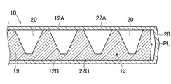
- such a sandwich panel 10 includes a front-side skin material sheet 12A, a back-side skin material sheet 12B, and a foamable core material interposed between both skin material sheets 12A and 12B. 13 and a decorative material sheet 14 bonded to the outer surface of the front surface skin sheet 12A.
- the sandwich panel 10 includes a decorative material sheet 14, a front surface skin material sheet 12A, and a core material. 13 and a laminated structure of the back side skin sheet 12B.
- the core material 13 is formed of a resin to which a foaming agent is added.
- resin forming the core material 13 polyolefins (for example, polypropylene and high density polyethylene) which are homopolymers or copolymers of olefins such as ethylene, propylene, butene, isoprene pentene and methylpentene, polyamide, polystyrene, Acrylic derivatives such as polyvinyl chloride, polyacrylonitrile, ethylene-ethyl acrylate copolymers, polycarbonate, vinyl acetate copolymers such as ethylene-vinyl acetate copolymers, terpolymers such as ionomers, ethylene-propylene-dienes, acrylonitrile -Styrene copolymer, ABS resin, polyphenylene oxide, polyacetal, thermoplastic resin such as thermoplastic polyimide, phenol resin, melamine resin, epoxy resin, polyurethane, thermosetting polyimide It includes
- the core material 13 may contain an additive.
- the additive include silica, mica, talc, calcium carbonate, glass fiber, carbon fiber, and other inorganic fillers, plasticizers, stabilizers, colorants, and charging agents.
- An inhibitor, a flame retardant, a foaming agent, etc. are mentioned.
- thermoplastic resins olefin resins or resins mainly composed of olefin resins
- polypropylene resins or resins mainly composed of polypropylene resins are weldable with decorative material sheets such as nonwoven fabric, mechanical strength and It is preferable in terms of excellent balance of moldability.
- polyolefin resin polypropylene having a melt tension at 230 ° C. in the range of 30 to 350 mN is used.
- polypropylene a propylene homopolymer, an ethylene-propylene block copolymer, an ethylene-propylene random copolymer, and a mixture thereof can be used.
- any of a physical foaming agent, a chemical foaming agent and a mixture thereof may be used.
- physical foaming agents inorganic physical foaming agents such as air, carbon dioxide, nitrogen gas, and water, and organic physical foaming agents such as butane, pentane, hexane, dichloromethane, dichloroethane, and their supercritical fluids are used. be able to.
- supercritical fluid carbon dioxide, nitrogen or the like is preferably used. If nitrogen is used, the critical temperature is 149.1 ° C. and the critical pressure is 3.4 MPa or more. If carbon dioxide is used, the critical temperature is 31 ° C. and the critical pressure is 7 It is obtained by setting it to 4 MPa or more.
- the amount of the foaming agent is a desired void volume due to innumerable bubbles formed inside the core material 13 by foaming, while the foaming ratio is too high, so that the skin material of the core material 13 As the rigidity against the compressive load in the direction orthogonal to the adhesive surface with the sheet 12 does not decrease more than necessary, or the expansion ratio is too high, the number of closed cells of countless bubbles decreases, and the heat insulation performance is reduced. It is determined not to decline.
- the total void volume required for the core material 13 is determined, and the infinite number of bubbles inside the core material 13 and the core material described later
- the expansion ratio that is, the addition amount of the foaming agent, may be determined based on the void volume allocated to the innumerable bubbles by allocating to the void portions formed by the plurality of depressions 20 formed on the surface of 13.
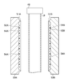
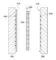
- the core material 13 is composed of a pair of thermoplastic resin plate materials 16, and each of the pair of thermoplastic resin plate materials 16 has a plurality of dents 20 tapered toward the inner surface 18 side on the outer surface 22. Each of the plurality of depressions 20 is bottomed, has a flat surface portion 24 at the foremost detail, and the planar portions 24 of the corresponding depressions 20 of the pair of thermoplastic resin plate materials 16 face each other.
- the core material 13 is formed by butt welding.
- Each of the pair of thermoplastic resin plate members 16 is welded at a portion where the corresponding skin material sheet 12 and the depression 20 are not formed on the surface thereof.
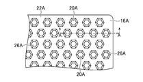
- the opening 26 on the outer surface 22 of the core member 13 is a regular hexagonal pyramid, and the openings 26 are arranged on the outer surface 22 in a honeycomb shape.
- the plurality of depressions 20 on the outer surface 22 of the core member 13 most densely.
- the size of the opening 26 of each of the plurality of depressions 20, the depth of the depressions, and the interval between adjacent depressions the larger the size of the opening 26, the deeper the depression, and the smaller the interval between adjacent depressions, It is possible to improve the porosity of the core material 13 as a whole, which contributes to weight reduction. However, as described later, it is necessary to determine from the viewpoint of rigidity required for the entire sandwich panel 10.
- the recess 20 formed in the core member 13 has a tapered shape toward the inside of the core member 13, and the thin wall portion serving as the width (D1) of the opening of the recess 20 and the bottom surface of the recess 20.
- the width (D2) of 5 is appropriately selected according to the thickness of the core material 13.
- D1 is 5 to 50 mm, preferably 5 to 25 mm, and D2 is in the range of 1 to 30 mm, preferably 1 to 15 mm. can do.
- the plurality of depressions 20 are preferably distributed evenly on the outer surface 22 of the core member 13, but the shapes thereof are a cone shape, a truncated cone shape, a cylindrical shape, a prism shape, a pyramid shape, and a hemispherical shape. What is necessary is just to select suitably from various shapes.
- thermoplastic resin core material 13 for the sandwich panel 10 is formed so as to have a sealed hollow portion 28 at a desired position inside the sandwich panel 10 and to exhibit a desired surface shape.
- the thermoplastic resin core material 13 is formed so as to have a sealed hollow portion 28 at a desired position inside the sandwich panel 10 and to exhibit a desired surface shape.
- the sandwich panel core 13 is bonded to the corresponding resin skin material sheet 12, and the outer shape according to the use of the sandwich panel 10 or It is possible to provide the sandwich panel core 13 capable of realizing the surface shape and the internal structure as desired.
- the peripheral surfaces of the resin skin sheets 12 facing each other with the core material 13 interposed therebetween are welded to each other, so that a parting line PL is formed, and it is possible to contribute to improving the rigidity of the entire sandwich panel 10. .
- the abutting flat surface portion 24 is formed by an opening peripheral edge portion formed on the opposing surfaces of the pair of thermoplastic resin plate materials 16, and the corresponding recesses 20 of each of the pair of thermoplastic resin plate materials 16 are abutted.
- the core member 13 having a through hole may be formed by butt welding in a form in which the parts face each other.
- the through hole 27 may be formed by eliminating the thin portion shown in FIG. 4.
- a void portion may be further improved by providing a hollow portion in a solid portion between a plurality of adjacent recesses 20.
- a plurality of depressions 20 are provided only on one outer surface 22A of the core member 13 and the depth of each depression 20 extends to the other outer surface 22B of the core member 13. There may be no degree.
- FIG. 23 when a plurality of recesses 20 are provided on both outer surfaces 22A and 22B of the core member 13, unlike FIGS. 4 and 5, the recesses 20 and 22B on the outer surface 22A are formed.
- the dents 20 may be arranged alternately, and the depth of the dents 20 may not reach the outer surface 22 of the counterpart of the core member 13.
- each of the plurality of depressions 20 is constituted by an annular rib 21, and the size and shape of the opening 26 on both outer surfaces 22 ⁇ / b> A and 22 ⁇ / b> B formed by the annular rib 21 or the thickness of the annular rib 21 and the like.
- the average density (x) of the core material 13 is a value obtained by dividing the weight of the core material 13 by the volume of the core material 13 excluding the recess 20 and the hollow portion 19, and the volume excluding the recess 20 and the hollow portion 19 is 23. It is possible to measure by submerging the core material 13 cut into a predetermined size in water at 0 ° C.
- the effective density (y) of the core material 13 is a value obtained by dividing the weight of the core material 13 by the virtual volume of the core material 13 including the recess 20. That is, in the sandwich panel 10, since the core material 13 is sandwiched between the two skin material sheets 12, the substantial volume occupied by the core material 13 formed between the two skin material sheets is the depression 20. The volume is included.
- the value of the effective density (y) can be obtained as a value obtained by adding the volumes of all the depressions 20 and the hollow portions 19 to the volume measured by submerging the core material 13 in the 23 ° C. water. In addition, the volume can also be obtained from the outer dimensions of the core material 13 simply. (Formula 1) 0.05x ⁇ y ⁇ 0.85x
- the effective density (y) When the effective density (y) is not so small as compared with the average density (x) of the core material 13 (y> 0.85x), the weight reduction by the depression 20 cannot be achieved. In addition, when the effective density (y) is too small compared to the average density (x) of the core material 13 (y ⁇ 0.05x), the proportion occupied by the depressions 20 becomes too high, and the adhesion to the skin material. The strength decreases, and the rigidity of the sandwich structure decreases.
- the expansion ratio of the core material 13 can be adjusted as appropriate to a range of about 30 times (average density 0.03 g / cm 3 in terms of polypropylene with a specific gravity of 0.90 g / cm 3), but it is a lightweight and highly rigid sandwich panel. From the viewpoint of obtaining 10, the range is 10 times or less, preferably 5.0 times or less.
- the maximum shear stress is applied to the core material 13 positioned in the intermediate layer.
- the core material 13 can withstand shear stress and compressive force in the thickness direction of the panel and is not easily crushed, and a lightweight and highly rigid sandwich panel 10 can be obtained.
- the skin material sheet 12 is a sheet formed of polyolefin resin such as polypropylene, engineering plastics or the like. From the viewpoint of securing the space between the skin material sheets 12 provided on both sides of the core material 13, that is, the bulk (thickness) of the core material 13, and ensuring the rigidity of the sandwich panel 10 as a whole, particularly the bending rigidity. As the rigidity, a material that is at least higher than the rigidity of the core member 13 is required.
- the skin material sheet 12 constitutes an upper surface wall and a lower surface wall of the sandwich panel 10, and preferably, the outer skin material sheet 12 a and the skin material sheet 12 b are welded and integrated at the outer periphery of the sandwich panel 10 by the pinch-off portion 8. To do.
- the skin material sheet 12 is preferably made of a resin material having a high melt tension from the viewpoint of preventing the occurrence of variations in thickness due to drawdown, neck-in, or the like. In order to improve transferability and followability, it is preferable to use a resin material with high fluidity.
- polyolefin for example, polypropylene, high-density polyethylene
- polypropylene high-density polyethylene
- olefins such as ethylene, propylene, butene, isoprene pentene, and methyl pentene
- MFR JIS K
- a strand is extruded from an orifice with a length of 8 mm, and the tension when the strand is wound around a roller with a diameter of 50 mm at a winding speed of 100 rpm is 50 mN or more, preferably 120 mN or more.
- a hydrogenated styrene-based thermoplastic elastomer is added in a range of less than 30 wt%, preferably less than 15 wt%.
- styrene-ethylene / butylene-styrene block copolymers, styrene-ethylene / propylene-styrene block copolymers, hydrogenated styrene-butadiene rubbers and mixtures thereof are suitable as hydrogenated styrene-based thermoplastic elastomers.
- the styrene content is less than 30 wt%, preferably less than 20 wt%, and the MFR at 230 ° C. (measured at a test temperature of 230 ° C. and a test load of 2.16 kg according to JIS K-7210) is 1.0 to 10 g / 10 Minute, preferably 5.0 g / 10 min or less and 1.0 g / 10 min or more.
- the skin material sheet 12 may contain an additive in the same manner as the core material 13.
- the additive include inorganic fillers such as silica, mica, talc, calcium carbonate, glass fiber, and carbon fiber, and plastics. Agents, stabilizers, colorants, antistatic agents, flame retardants, foaming agents and the like. Specifically, silica, mica, glass fiber or the like is added in an amount of 50 wt% or less, preferably 30 to 40 wt% with respect to the molding resin.
- the decorative material sheet 14 is an object that improves appearance, decoration, and contacts with the molded product (for example, in the case of a cargo floor board, placed on the upper surface of the board). Configured for the purpose of protecting the baggage, etc.).
- a fiber skin material sheet-like skin material, a film-like skin material, or the like is applied as the material of the decorative material sheet 14.
- synthetic fibers such as polyester, polypropylene, polyamide, polyurethane, acrylic and vinylon, semi-synthetic fibers such as acetate and rayon, regenerated fibers such as viscose rayon and copper ammonia rayon, cotton, hemp, Examples thereof include natural fibers such as wool and silk, or blended fibers thereof.
- synthetic fibers such as polyester, polypropylene, polyamide, polyurethane, acrylic and vinylon
- semi-synthetic fibers such as acetate and rayon
- regenerated fibers such as viscose rayon and copper ammonia rayon, cotton, hemp
- natural fibers such as wool and silk
- blended fibers thereof it is preferable that it is a nonwoven fabric which consists of polyester with a fabric weight of 150 g / m ⁇ 2> or more from a viewpoint of a touch feeling, durability, and a moldability.
- the tensile strength of the decorative material is preferably 15 kg / cm 2 or more, and the elongation is preferably 30% or more from the viewpoints of three-dimensional shape reproducibility and moldability.
- the tensile strength and elongation values were measured in accordance with JIS-K-7113 at a temperature of 20 ° C.
- the skin material 10 is a sheet-like decorative material, a film-like decorative material instead of the above-mentioned non-woven fabric etc., a thermoplastic elastomer, an embossed resin sheet, a resin sheet with a printed layer attached to the outer surface, a synthetic material Leather, non-slip mesh-shaped skin sheets, etc. can be used.
- the core material 13 is made of foamed resin, and at least one outer surface 22 is formed with an opening 26 and extends inward, and the corresponding skin material.
- the void volume can be easily adjusted by the bubbles formed inside the core member 13, while the plurality of depressions 20 provided on at least one outer surface 22.
- the number or volume of the cores it is possible to avoid specialization or complication of the molding method of the core material 13 having the depressions 20 as compared to securing the void volume necessary for weight reduction by the depressions 20 alone. Is possible.
- the bubbles are formed inside the core material 13, and therefore the adhesive surface with the corresponding skin material sheet 12.
- the opening 26 due to the formation of bubbles does not occur on at least one of the surfaces, but the expansion ratio inevitably increases, thereby reducing the compression rigidity in the thickness direction of the core member 13.
- the solid portion 19 of the foamed resin other than the depression 20 has a function of supporting the compressive load in the thickness direction of the core material 13.
- the adhesion area with the corresponding skin material sheet 12 on at least one outer surface 22 is reduced, whereby the bending rigidity or the sandwich panel 10 as a whole is reduced.
- the rigidity is reduced. Therefore, in order to reduce the weight of the sandwich panel 10, the number of the recesses 20 and the total opening area are appropriately determined to ensure the bending rigidity or the shear rigidity of the sandwich panel 10 as a whole and to compress the core material itself. It is possible to achieve both ensuring of rigidity.
- each of the pair of split molds 50 is a pair of split molds.
- the cavities 52 for shaping the parison P supplied between the molds 50 are arranged so as to face each other, and the surface of each cavity 52 has an annular pinch-off substantially along the outer peripheral edge of the cavity 52.
- a portion 51 is provided, and a plurality of protrusions 54 are formed inside the pinch-off portion 51, and each of the plurality of protrusions 54 moves the mold 50 to the open position after molding the core 13 in the closed position.
- the taper is tapered toward the opposite mold 50.
- the taper angle ⁇ is preferably at least 75 ° or more with respect to the longitudinal direction of the core member 13.
- Each of the plurality of protrusions 54 has a regular hexagonal truncated pyramid shape. Accordingly, when the mold 50 is moved to the closed position and the mold 50 is clamped, the melted parison P in the two molds 50 is pressed toward the cavities 52 of the two divided molds 50.
- a polyolefin resin is supplied to an extruder (not shown), kneaded while being heated and melted, a predetermined amount of foaming agent is added, and further kneaded in the extruder to obtain a foamable molten resin.
- the accumulator (not shown) is filled with the molten resin while maintaining the resin temperature suitable for foaming and the pressure at which the foamable molten resin does not start foaming.
- the ram (not shown) of the accumulator while the gate at the die tip of the extrusion head 40 is opened, the foamable molten resin is opened to the low pressure region, and the foamable cylindrical parison P is formed. Is done.
- the foaming ratio is kept substantially constant during the molding process by the split mold 50 in the subsequent process.
- the molten cylindrical parison P is extruded vertically downward through a slit die from the known extrusion head 40, and the continuous molten cylindrical parison P is in two open molds in the open position. Supply between 50.
- the two divided molds 50 are moved from the open position to the closed position, and the two divided molds 50 are clamped. Thereby, a sealed space is configured.
- the parison P in the sealed space is pressed toward the cavity 52 and shaped along the cavity 52.
- the parison P is directed toward the cavity 52 by inserting a blow pin (not shown) into the core member 13 and introducing a pressurized fluid therein, as in a conventionally known method.
- a parison (not shown) communicating with the sealed space is provided in the split mold 50 and the sealed space is sucked through this channel, as in a conventionally known method. P is sucked toward the cavity 52, and the parison P is brought into close contact with the cavity 52.
- thermoplastic resin plate material 16 is constituted by the continuous cylindrical parison P in the molten state, and a plurality of the cavities 52 are formed on the surfaces of the pair of thermoplastic resin plate materials 16 facing the corresponding cavities 52.
- the protrusions 54 are inserted, and a plurality of depressions 20 corresponding to the plurality of protrusions 54 are formed on the opposing surface.
- Each of the plurality of recesses 20 is formed so as to protrude on the surface opposite to the opposing surface, that is, on the inner surface 18 side, thereby forming a butt plane portion 24 that forms the bottom.
- the arrangement form of the plurality of protrusions in the cavity 52 is made common, so that in each of the pair of thermoplastic resin plate materials 16, the corresponding flat surface portions 24 of the corresponding recesses 20 Are welded, and the pinch-off portions of the respective molds 50 come into contact with each other, so that the continuous cylindrical parison P is welded at the same time as the parting line PL is formed on the peripheral edge thereof.
- the two split molds 50 are moved from the closed position to the open position by the mold driving device, and the two split molds 50 are opened.
- the molded core material 13 is taken out from between the two split molds 50.
- the molding of the foamable core material 13 is completed.
- FIG. 9 to FIG. 11 are modifications in which dents 20 having different sizes are unevenly distributed as the core material 13, thereby changing the internal structure of the core material 13 in the longitudinal direction (height direction).
- two extrusion heads are provided (40A, 40B), and a continuous sheet parison P is extruded from each.
- the recesses 20 having different sizes are unevenly distributed only for the continuous sheet-like parison P on the right side of the drawing, and the recesses 20 having the same size are provided for the continuous sheet-like parison P on the left side as in FIGS. It is evenly distributed in the longitudinal direction (height direction).
- protrusions 54 having different sizes are provided in the cavity 52 of the mold 50 on the right side of the drawing. More specifically, as in FIGS. 4 to 8, in addition to the truncated pyramid shaped recess 20, a truncated pyramid shaped recess 20 having a width in the longitudinal direction (height direction) is provided. As a result, as shown in FIG. 10, the mold 20 is clamped to form a dent 20 with a wide bottom face in the right continuous sheet-like parison P, and the left continuous sheet-like parison is formed on the bottom face. The butted bottom surfaces of the two depressions 20 formed in P are butted. According to the core material 13 having such a configuration, the internal structure is maintained in the longitudinal direction of the core material 13 while maintaining the closed cell ratio by suppressing an increase in the expansion ratio and ensuring heat insulation or sound absorption. And the local intensity can be distributed as desired.
- a molten foamable parison P may be formed before the two split molds 50 are clamped. That is, after positioning the sheet-like parison P of the two thermoplastic resin materials between the pair of split molds 50 in a form that protrudes around the cavity 52 of the pair of split molds 50, the pair of split molds 50.
- a sheet-like parison against a pair of protrusions (not shown) spaced from each other in the cavities 52 of the type mold 50 and projecting from the cavity 52 toward the opposing mold 50 A step of forming a sealed space between the cavity 52 of the pair of split molds 50 and the sheet-shaped parison P by abutting P, and sucking the sheet-shaped parison P through the sealed space The parison P is pressed against the cavity 52 of the pair of split molds 50 and shaped, and the pair of split molds 50 are clamped to form two sheets.
- the shaping step is a plurality of protrusions 54 provided in at least one cavity 52 of the pair of split molds 50, each having a tapered shape toward the opposing split mold 50.
- the plurality of depressions 20 corresponding to the plurality of protrusions 54 are preferably formed on the surface of the sheet-like parison P by pressing the corresponding sheet-like parison P against the plurality of protrusions 54 having the above.
- a plurality of recesses 20 corresponding to the plurality of protrusions 54 may be formed on the surface of the sheet-like parison P through press working by clamping the pair of split molds 50. According to such a method, there is no need to pressurize or depressurize the sealed space formed in the pair of molds 50 by clamping, so the foamable sheet parison P disposed in the sealed space.
- the innumerable bubbles formed in the inside of the inside are affected by the pressure change in such a sealed space, and in some cases, the bubbles are crushed, or adjacent bubbles are connected to each other, and the independent bubble rate is reduced, or conversely It is possible to avoid the situation where bubbles expand.
- the method for forming the core material 13 by sandwiching the foamed resin such as foam blow molding with the split mold has been described.
- the split metal in the state in which the foamed resin such as foam injection molding or foam bead molding is clamped. It can also be produced by known methods of injection or filling into the mold.
- an apparatus and a method for forming the sandwich panel 10 using a mold using the core material 13 thus formed will be described.
- the molding device 60 of the sandwich panel 10 includes an extrusion device 62 and a mold clamping device 64 disposed below the extrusion device 62, and a molten parison extruded from the extrusion device 62. P is sent to the mold clamping device 64, and the melted parison P is molded by the mold clamping device 64.
- the extruding device 62 is a conventionally known type, and detailed description thereof is omitted. However, a cylinder 66 provided with a hopper 65, a screw (not shown) provided in the cylinder 66, and a screw are connected to the screw. A hydraulic motor 68, an accumulator 70 communicating with the inside of the cylinder 66, and a plunger 72 provided in the accumulator 70, and resin pellets introduced from the hopper 65 are screwed by the hydraulic motor 68 in the cylinder 66. The molten resin is melted and kneaded by the rotation of the resin, and the molten resin is transferred to the accumulator chamber and stored in a certain amount.
- the plunger 72 is driven to feed the molten resin toward the T die 71 and continuously through the die slit (not shown).
- the extrusion capability of the extrusion device 62 is appropriately selected from the viewpoints of the foaming ratio to be achieved and the closed cell ratio, the size of the skin material sheet 12 to be molded, and the prevention of the drawdown of the parison P. More specifically, if the extrusion speed of the resin from the die slit is too high, the foaming ratio is reduced while the closed cell ratio is reduced. On the other hand, if the extrusion speed is too slow, the foam is overfoamed. Since the closed cell ratio is lowered, it is necessary to determine the extrusion speed from the viewpoint of the functions required of the core material 13, particularly the strength, the heat insulating property, and the sound absorbing property.
- the extrusion rate of the resin from the die slit is several hundred kg / hour or more, more preferably 700 kg / hour or more.
- the extrusion process of the parison P is as short as possible and generally depends on the type of resin and the MFR value, but generally the extrusion process is within 40 seconds, more preferably It should be completed within 30 seconds.
- the extrusion area per unit area and unit time of the thermoplastic resin from the die slit is 50 kg / hour cm 2 or more, more preferably 60 kg / hour cm 2 or more.
- the die slit is arranged vertically downward, and the continuous sheet-like parison extruded from the die slit is sent vertically downward in a form that hangs down from the die slit.
- the width of the die slit variable, the thickness of the continuous sheet-like parison P can be changed.
- the mold clamping device 64 is also a conventionally known type like the extrusion device 62, and detailed description thereof will be omitted.
- two divided molds 73 and a sheet-like parison in which the mold 73 is melted are used.
- a mold driving device is moved between the open position and the closed position in a direction substantially perpendicular to the supply direction of P.
- the two divided molds 73 are arranged with the cavities 74 facing each other, and are arranged so that the cavities 74 are directed substantially in the vertical direction. More precisely, on the surface of each cavity 74, on the inner side of an annular pinch-off portion 76 described later, the outer shape and surface shape of the skin material sheet 12 formed on the basis of the melted sheet-like parison P Corrugated portions are provided according to the above.
- a pinch-off portion 76 is formed around the cavity 74.
- the pinch-off portion 76 is formed in an annular shape around the cavity 74 and protrudes toward the opposing mold 73. To do. As a result, when the two divided molds 73 are clamped, the tip portions of the respective pinch-off portions 76 come into contact with each other so that a parting line PL is formed at the periphery of the molten parison P.
- a pair of frame members 75 are disposed between the two divided molds 73 so as to be nested with the pair of molds 73 and substantially parallel to the cavity 74, and each of the pair of frame members 75 has an opening 77.
- the pair of frame members 75 are moved in the horizontal direction by a frame member driving device (not shown). As a result, each of the pair of frame members 75 moves toward the corresponding parison P in the molten state, holds the parison P, and the tip of the pinch-off portion 76 of the corresponding mold 73 opens in the opposite direction in that state. 77, it can be moved to the surface of the parison P through contact.
- the mold driving device is the same as the conventional one, and the description thereof is omitted.
- the two divided molds 73 are each driven by the mold driving device, and in the open position, the two divided molds are used.
- two continuous sheet-like parisons P in a molten state can be arranged with a space between each other, and in the closed position, the pinch-off portions 76 of the two split molds 73 come into contact with each other.
- the pinch-off portions 76 come into contact with each other so that a sealed space is formed in the two divided molds 73.
- the closed position is the position of the center line of the continuous sheet-like parison P in the molten state of the two strips, and each mold 73 is driven by the mold driving device. Has been moved toward that position.
- a method for forming the sandwich panel 10 will be described.
- the sheet-shaped decorative material sheet 14 is inserted between one split mold 73 and one frame member 75 from the side of the two split molds 73, and one split mold is inserted.
- a sheet-like decorative material sheet 14 is temporarily fixed by a temporary fixing pin (not shown) provided on the mold 73 so as to cover the cavity 74 of one split mold 73.
- the molten thermoplastic resin parison P is extruded vertically downward from each die slit, and two continuous sheet parisons P are supplied between the two divided molds 73.
- the pair of frame members 75 are moved toward the corresponding continuous sheet-like parison P by the frame member driving device.
- the pinch-off portion 76 of the mold 50 passes through the opening 77 of the frame member 75 toward the corresponding divided mold 73, and the frame member 75 holding the continuous sheet-shaped parison P is moved to the corresponding divided mold 73. It moves until it comes into contact with the surface of the P facing the cavity 74. Thereby, a sealed space is formed by the surface of the continuous sheet-like parison P facing the cavity 74, the pinch-off portion 76 and the cavity 74.
- the inside of the sealed space is sucked through the respective divided molds 73, whereby the corresponding continuous sheet-like parison P is pressed against the cavity 74 and shaped into a shape along the cavity 74. Is done.
- the continuous sheet-like parison P on the left side of the drawing is shaped and welded to the decorative sheet 14 interposed between the continuous sheet-like parison P and the cavity 74.
- the core material 13 held by the suction disk 78 of the manipulator (not shown) is inserted between the two divided molds 73 from the side.
- the manipulator is moved in the horizontal direction toward the right split mold 73, so that the core with respect to the continuous sheet-like parison P adsorbed in the cavity 74 of the right split mold 73.
- the material 13 is pressed. Thereby, the core material 13 is welded to the continuous sheet-like parison P.
- the suction disk 78 is detached from the core material 13 and the manipulator is pulled out between the two divided molds 73 to prepare for mold clamping.
- the two divided molds 73 are moved from the open position to the closed position by the mold driving device so as to approach each other, and the mold is clamped.
- the core material 13 welded to one continuous sheet-like parison P (right side of the drawing) is welded to the other sheet-like parison P, and the peripheral edges of the continuous sheet-like parisons P are welded to the parting line. PL is formed.
- the core material 13 itself is welded to the melted skin material sheet 12 in a cold state, which is different from the skin material sheet 12, so that the core material 13 itself is a mold. It is positioned in advance so as not to be deformed by tightening.
- FIG. 20 is a front view of the shaped skin material sheet 12 and the welded core material 13 as seen from the cavity 74 of one mold 73.
- 109 is a protrusion forming portion of the cavity 74
- 110 is a handle forming mold protrusion
- the core member 13 has a shape slightly smaller than the mold cavity, and is a shape that avoids the handle forming mold protrusion.
- the two split molds 73 are opened, the cavity 74 is separated from the completed sandwich panel 10, and burrs formed around the parting line PL are removed.
- the molding of the sandwich panel 10 is completed.
- the core material 13 which is a component of the sandwich panel 10 demonstrated the case where it comprised by a pair of thermoplastic resin board
- the present invention is not limited thereto, and molding may be performed using a molten tubular or sheet-like parison P alone.
- each of the pair of thermoplastic resin plate materials 16 is blow-molded or vacuum-molded based on the thermoplastic parison P of the thermoplastic resin material using the two divided molds 50 has been described. Without being limited, as long as strong adhesiveness between the pair of thermoplastic resin plate materials 16 is ensured, it may be formed by sheet molding (compression molding) using two divided molds 50.
- the core material 13 is comprised by a pair of thermoplastic resin board material 16, and each of a pair of thermoplastic resin board material 16 has the several hollow 20 in the surface, and a plurality of hollows
- each of 20 has the form which protrudes in the other surface side, in the pair of thermoplastic resin board materials 16, the case where the butting
- each of the pair of thermoplastic resin plate members 16 has a plurality of dents 20 on the surface thereof, but the dents 20 are not in a form protruding on the other surface side.
- the case where the butt plane part 24 is not welded may be sufficient.
- the decorative material sheet 14 was bonded with respect to the front surface skin material sheet 12 which exhibits an external appearance as the sandwich panel 10 used for a cargo floor board was demonstrated, it is limited to it. Instead, the decorative material sheet 14 may be omitted, and the front surface skin material sheet 12 may be exposed as it is.
- it is not limited to the sandwich panel 10 used for the cargo floor board, but is used for automobile interior materials such as footrests, side door trims, seat backs, rear parcel shelves, door panels, seat seats, carrying cases for machinery and equipment, and light electrical products. It is suitably used for applications such as tanks, dust, cases, housings, trays, containers, etc., as well as interior materials for buildings such as parts, wall materials and partitions, furniture such as chairs, etc.
- the present inventor conducted a confirmation test on the possibility of practical molding of a so-called hybrid sandwich panel in which a plurality of depressions are provided on the surface of a foamable core material.
- a propylene homopolymer (PF814, manufactured by Sun Allomer Co., Ltd.) into which a long chain branched structure having an MFR of 3.0 g / min at 230 ° C. was introduced as a thermoplastic resin, and talc relative to the propylene homopolymer as a foaming agent and a nucleating agent.
- an in-die accumulator which is a cylindrical space between the mandrel and die outer cylinder, and is divided into a split mold as a cylindrical parison using a ring piston.
- Example 1 After extrusion and mold clamping, air was blown into the parison at a pressure of 0.1 MPa to obtain a core material 13 (sample 1) having a thickness of 15 mm having a plurality of indentations 20 and hollow portions 19 each having a regular hexagonal shape of approximately 4 mm on a side. It was. MFR is measured under a test load of 2.16 kg according to JIS K-7210.
- the accumulator used in the present invention has an injection rate of 200 cm 3 / sec or more, preferably 500 cm. Those of 3 / sec or more are used.
- the average density of the core material 13 obtained in Example 1 is 0.1 g / cm 3 (foaming ratio conversion: 9 times), and the effective density is 0.06 g / cm. 3 (foaming ratio conversion: equivalent to 15 times).
- a solid core material 13 (sample 2) having a thickness of 15 mm and having a plurality of hollows 20 each having a regular hexagonal shape was obtained.
- the average density of the core material 13 obtained in Example 2 is 0.1 g / cm 3 (foaming ratio conversion: 9 times), and the effective density is 0.08 g / cm. 3 (foaming ratio conversion: equivalent to 11 times).
- a solid core material 13 (sample 3) having a solid thickness of 15 mm and having a plurality of depressions 20 made of a regular hexagon having a side of approximately 4 mm was obtained in the same manner as in Example 2 except that the amount of foaming agent added was reduced. .
- the average density of the core material 13 obtained in Example 3 is 0.13 g / cm 3 (foaming ratio conversion: 7 times), and the effective density is 0.11 g / cm. 3 (foaming ratio conversion: equivalent to 8 times).
- a crystalline ethylene-propylene block copolymer (Novatech PP EC9, manufactured by Nippon Polychem Co., Ltd.) having a MFR of 0.5 g / min at 230 ° C.
- the sheet was extruded from the T die as two sheets, the split mold was clamped, the core material 13 was sandwiched between the two sheets, and after cooling, it was taken out from the mold to obtain the sandwich panel 10.
- the practical formability of so-called hybrid sandwich panels was confirmed.
- the inventor has confirmed through tests that the influence of the plurality of depressions provided on the surface of the foamable core material on the compression rigidity of the core material.
- Core material specifications Five types of samples 1 to 5 were prepared. Samples 1 to 3 obtained in Examples 1 to 3 were used. For samples 4 and 5, a commercially available polypropylene foam plate (EPP) that was foamed in-mold using foam beads and cut into a 15 mm thick plate was used. Sample 4 with an expansion ratio of 15 times and Sample 5 with an expansion ratio of 11 times.
- EPP polypropylene foam plate
- the core material innumerable bubbles are provided inside by foaming, and when the weight is reduced by a so-called hybrid core material having a plurality of depressions on the surface, the total void volume is reduced by the infinite number of air bubbles and a plurality of void volumes.
- the concave portion it has been found that it is effective to provide the void by a plurality of concave portions from the viewpoint of securing the compression rigidity of the core material itself.
- FIG. 4 It is a figure showing the state where sandwich panel 10 concerning a 1st embodiment of the present invention was applied to the cargo floor lid of a car. It is a section perspective view which fractures and shows a part of sandwich panel 10 concerning a 1st embodiment of the present invention. It is a front view of the core material for sandwich panels concerning a 1st embodiment of the present invention. It is sectional drawing of the sandwich panel 10 corresponding to the AA arrow direction of FIG. It is sectional drawing of the same sandwich panel 10 as FIG. 4 which shows a modification. It is a figure which shows the state before the mold clamping in the formation process of the core material for sandwich panels which concerns on 1st Embodiment of this invention.
- FIG. 6 shows the state before the mold clamping in the formation process of the core material for sandwich panels which concerns on the deformation
- FIG. 7 shows the mold clamping state in the formation process of the core material for sandwich panels which concerns on the deformation
- FIG. 7 shows the mold clamping state in the formation process of the core material for sandwich panels which concerns on the deformation
Landscapes
- Engineering & Computer Science (AREA)
- Mechanical Engineering (AREA)
- Architecture (AREA)
- Chemical & Material Sciences (AREA)
- Composite Materials (AREA)
- Civil Engineering (AREA)
- Structural Engineering (AREA)
- Laminated Bodies (AREA)
- Blow-Moulding Or Thermoforming Of Plastics Or The Like (AREA)
Abstract
Description
サンドイッチパネルは、2枚の表皮材シート、両表皮材シートとの間に介在する芯材とを有し、表皮材シート、芯材および表皮材シートの積層構造が基本的形態であるが、用途に応じてサンドイッチパネルに要求される機能が変わる。
たとえば、浴室に使用される内装パネルのように、外観上の美観が重視される反面、それほどの強度が要求されない場合には、外観を呈するおもて面側表皮材シートにさらに化粧材が貼り合わせられ、化粧材の表面性状あるいは全体成形形状が重視され、構造材としての用途の場合には、外観上の美観より強度が要求される。
この点、自動車、航空機等の輸送機械の内装材部品、特に車両用のカーゴフロアボード、デッキボード、リアパーセルシェルフ等は、燃費向上の観点から軽量化が要求されるとともに強度が要求されることから、両表皮材シートおよび芯材が樹脂製である樹脂製のサンドイッチパネルが多用されてきた。
従来、このようなサンドイッチパネルは、用途に向けた外形形状に対応するために、両表皮材シートおよび芯材それぞれが個別に切断加工等により製造され、用意された両表皮材シートおよび芯材同士を組み付け、接着等することにより完成してきた。
一方で、両表皮材シートおよび芯材が樹脂製である樹脂製のサンドイッチパネルは、各種の成形方法により製造されてきた。
特許文献1は、押出成形による樹脂製のサンドイッチパネルの成形方法を開示する。
この成形方法は、サンドイッチパネルを構成する各表層をそれぞれ、Tダイから押し出して、溶融状態の表層の溶融熱を利用して各表層を溶着することにより、層間の接着性が良好なサンドイッチパネルを連続的に製造することが可能である。
特許文献2は、射出成形による樹脂製のサンドイッチパネルの成形方法を開示する。
このような射出成形による樹脂製のサンドイッチパネルの成形方法によれば、断面形状が一定の成形体のみならず、断面形状が変化する自由な外形形状の成形体を製造することが可能であり、この点で、押出成形に比べて、成形物の形状に対する制約性が低い。
しかしながら、射出成形方法は、密閉金型空間内に溶融樹脂を圧入し、密閉金型内面に押し付けることにより、溶融樹脂を賦形する形態を採用することから、射出成形方法単独で、内部に密閉中空部を有する成形体を成形することは、技術的に困難である。
特許文献3ないし特許文献7にはいずれも、発泡芯材を上下一対のスキン材で挟み込んだ少なくとも3層構造からなるサンドイッチ構造体が開示されている。
特許文献6は、発泡体として4ないし12倍の発泡倍率を有するアクリロニトリルースチレン共重合体の発泡ビーズを用いて、一体プレスにより積層構造体を製造する点を開示する。
特許文献7は、特許文献6と同様に、発泡体としてポリスチレンの発泡ビーズを用いて、プレスにより多層パネルを製造する点を開示する。
以上のようなサンドイッチパネルによれば、発泡による気泡の形成、あるいは表面の窪みの形成により、軽量化を達成することが可能であるが、以下のような技術的問題点が存する。
第1に、発泡による気泡の形成のみ、あるいは表面の窪みの形成のみにより軽量化を図ろうとすると、サンドイッチパネルに要求される強度、断熱性、吸音性等他の機能が損なわれる点である。
また、特許文献3ないし特許文献7の場合、発泡倍率を上げることにより、芯材全体に亘って断熱性あるいは吸音性を向上可能であるが、気泡の形成位置を調整するのは困難であることから所望の剛性分布を得ることは困難である。
特に、発泡倍率を上げることにより、独立気泡率が低下する傾向にあるから、それにより断熱性は顕著に低下する。
第2に、サンドイッチパネルの成形方法に起因して、良好な品質のサンドイッチパネルを得るのが困難となる点である。
それに対して、特許文献8のように、表面に窪みを形成する場合、芯材を構成する一対の熱可塑性樹脂製板材同士の接着性が不良で、サンドイッチパネル全体として十分な曲げ剛性を奏することができない。
より詳細には、段ロールによれば、一対の樹脂製板材がロールの間に送られて、その位置で押圧力が付加されて接着されることから、一対の樹脂製板材同士の接着は、面接着より点接着に近くしかも接着時間が短いため、十分な接着性を確保できない。
この点、いわゆる金型を用いた成形によれば、金型による成形の制約から、複数の窪みは内方に向かって先細のテーパ角度を設けざるを得ないが、金型の型締により十分な溶着時間を確保可能であり、このような問題点を引き起こす恐れはない。
特許文献9は、金型による成形の1つであるシート成形(圧縮成形)による樹脂製サンドイッチパネルの製造方法を開示する。
より詳細には、2つの分割金型の間に、表皮材シートおよび芯材(場合により化粧材)を配置して、分割金型を型締することにより、金型内の表皮材シートおよび芯材を加圧して賦形するとともに、表皮材シートと芯材とを溶着することが可能であり、この点で一度にサンドイッチパネルを形成することが可能である。
しかしながら、型締により賦形あるいは溶着するためには、表皮材シートおよび芯材はいずれも、溶融状態とする必要があり、表皮材シートが、たとえば原反ロールから連続シートとして繰り出される場合には、赤外線ヒータ等で分割金型への配置前に再加熱する必要があり、このような再加熱に起因して、サンドイッチパネルを構造体としての用途に用いる場合、十分な強度を有するサンドイッチパネルを得るのが困難となる。より詳細には、上述のような再加熱の成形性への悪影響に起因して、表皮材シート同士の溶着部分である外周パーティングラインの溶着強度、あるいは表皮材と芯材との間の溶着強度が劣化するため、サンドイッチパネル全体としての強度が低下する。
以上の技術的課題に鑑み、本発明の目的は、サンドイッチパネルとして所望の剛性分布を達成しつつ、断熱性あるいは吸音性の向上が可能なサンドイッチパネルを提供することにある。
以上の技術的課題に鑑み、本発明の目的は、発泡倍率の調整が容易で、強度不足の発生を防止可能なサンドイッチパネル用芯材の成形方法およびサンドイッチパネルの成形方法を提供することにある。
2枚の樹脂製表皮材シートと、両表皮材シートの間に挟み込まれる形態で両表皮材シートそれぞれと面接着される熱可塑性樹脂製芯材とを有するサンドイッチパネルであって、
該熱可塑性樹脂製芯材は、所定発泡倍率を有する発泡樹脂製であり、
少なくとも一方の表面に、それぞれ開口を形成して内方に向かって延び、かつ対応する表皮材シートにより閉じられる空隙を内部に構成する複数の窪みを有し、
前記所定発泡倍率との関係で前記複数の窪みに割り当てられる所与の空隙体積のもとで、前記少なくとも一方の表面を介して、前記熱可塑性樹脂製芯材と対応する表皮材シートとの面接着を保持しつつ、前記熱可塑性樹脂製芯材のうち前記複数の窪みによる空隙を除いた発泡樹脂の中実部が、前記熱可塑性樹脂製芯材の厚み方向の圧縮荷重に対する支持機能を奏するように、前記複数の窪みの数およびその総開口面積が決定される、構成としている。
2枚の樹脂製表皮材シートと、両表皮材シートの間に挟み込まれる形態で両表皮材シートそれぞれと面接着される熱可塑性樹脂製芯材とを有するサンドイッチパネルであって、
該熱可塑性樹脂製芯材は、所定発泡倍率を有する発泡樹脂製であり、
少なくとも一方の表面に、それぞれ内方に向かって延び、かつ対応する表皮材シートにより閉じられる空隙を内部に構成する複数の窪みを有し、
前記複数の窪みそれぞれは、前記少なくとも一方の表面に開口を形成する環状リブにより構成され、
前記所定発泡倍率との関係で前記複数の窪みに割り当てられる所与の空隙体積のもとで、前記少なくとも一方の表面を介して、前記熱可塑性樹脂製芯材と対応する表皮材シートとの面接着を保持しつつ、前記熱可塑性樹脂製芯材の厚み方向の圧縮荷重に対する支持機能を奏するように、前記環状リブの数およびその環状形状が決定される、構成としている。
一対の熱可塑性樹脂製板材それぞれは、その表面において対応する表皮材シートと接着されるのがよい。
さらにまた、前記突き合わせ部は、一対の樹脂製板材の互いに対向する対向面に形成される開口周縁部により形成され、一対の樹脂製板材それぞれの対応する窪み同士の突き合わせ部が互いに背向する形態で突き合わせ溶着することにより、貫通穴を有する芯材が形成されるのでもよい。
加えて、前記複数の窪みはそれぞれ、前記熱可塑性樹脂製芯材の前記外表面における開口が正六角形の角錐台形状を有するのがよい。
さらに、前記複数の窪みは、前記熱可塑性樹脂製芯材の前記外表面上で、ハニカム状に配置されているのがよい。
また、前記熱可塑性樹脂製芯材の平均密度(x)と実効密度(y)との関係が、以下の関係式(0.05x≦y≦0.85x)を満たし、かつ前記熱可塑性樹脂製芯材の発泡倍率が、10倍以下であるのがよい。
さらに、前記環状リブの環状形状は、前記環状リブが形成する開口の大きさ、形状あるいは前記環状リブの厚みを含むのがよい。
さらにまた、前記環状リブそれぞれにより形成される開口の全周長と総開口面積とに基づいて、前記環状リブの数が決定されるのがよい。
上記目的を達成するために、本発明に係るサンドイッチパネル用熱可塑性樹脂製芯材の成形方法は、
2枚の樹脂製表皮材シートの間に介在する熱可塑性樹脂製芯材を有するサンドイッチパネル用熱可塑性樹脂製芯材の成形方法であって、
一対の分割形式の金型それぞれのキャビティの周縁部に形成された環状のピンチオフ部のまわりにはみ出す形態で、溶融状態の発泡性の熱可塑性樹脂製材料を一対の分割形式の金型間に位置決めする段階と、
一対の分割形式の金型を型締して、一対の分割形式の金型内に密閉空間を形成する段階と、
密閉空間内の溶融状態の発泡性の熱可塑性樹脂製材料中から、材料中に形成された気泡が破裂しないように加圧することにより、一対の分割形式の金型の少なくとも一方のキャビティのピンチオフ部の内側に設けられた突起部により熱可塑性樹脂製材料を賦形する段階と、を有し、
それにより、密閉空間内の熱可塑性樹脂製材料の少なくとも一方のキャビティに対向する表面に窪みを成形するとともに、熱可塑性樹脂製材料に中空部を設ける構成としている。
熱可塑性樹脂製芯材の内部に形成する無数の気泡のみにより、サンドイッチパネルの軽量化を達成するのに比べて、熱可塑性樹脂製芯材の表面に形成する複数の窪みにより形成される空隙部に依存することにより、発泡倍率を制限することが可能であり、それにより発泡倍率の増大に伴う調整の困難性を回避することが可能であるとともに、一対の金型を用いてサンドイッチパネルの構成部材である芯材と表皮材シートとを溶着することで、良好な接着性を確保することが可能であるから、発泡倍率の調整が容易で、強度不足の発生を防止可能である。
また、前記溶融状態の発泡性の熱可塑性樹脂製材料は、円筒状に押し出されたパリソンでもよい。
さらに、前記溶融状態の発泡性の熱可塑性樹脂製材料は、Tダイより押し出された連続シート状パリソンでもよい。
さらに、前記熱可塑性樹脂製材料は、押し出し機内に所定発泡倍率に必要な量の発泡剤を添加し、加熱混練することにより発泡性溶融樹脂とし、該発泡性溶融樹脂を所定の押し出し速度で押し出すことにより、発泡パリソンとして形成されるのがよい。
さらにまた、前記溶融状態の発泡性の熱可塑性樹脂製材料は、予め押し出し成形された発泡性の熱可塑性樹脂製材料を再加熱することにより溶融状態とするのでもよい。
上記目的を達成するために、本発明に係るサンドイッチパネル用熱可塑性樹脂製芯材の成形方法は、
2枚の樹脂製表皮材シートの間に介在する熱可塑性樹脂製芯材を有するサンドイッチパネル向けの熱可塑性樹脂製芯材の成形方法であって、
それぞれ、一対の分割形式の金型のキャビティの周縁部に形成された環状のピンチオフ部のまわりにはみ出す形態で、2条の発泡性の熱可塑性樹脂製材料のシート状パリソンを一対の分割形式の金型間に位置決めする段階と、
一対の分割形式の金型それぞれのキャビティにおいて、該キャビティから対向する分割形式の金型に向かって突出するように設けた環状のピンチオフ部に対して、対応するシート状パリソンを当接させて、一対の分割形式の金型のキャビティと対応するシート状パリソンとの間に密閉空間を形成する段階と、
該密閉空間を通じて対応するシート状パリソンを吸引することにより、対応するシート状パリソンを一対の分割形式の金型のピンチオフ部の内側に設けた複数の突起部に押し当てて、賦形する段階と、
一対の分割形式の金型を型締して、2条のシート状パリソン同士を溶着する段階と、を有し、
それにより、溶着された2条のシート状パリソンの周縁にパーティングラインを形成することを通じて、シート状パリソンの内部に密閉中空部を設けるとともに、シート状パリソンの表面に複数の窪みあるいは複数の貫通穴を設ける構成としている。
上記目的を達成するために、本発明に係るサンドイッチパネル用熱可塑性樹脂製芯材の成形方法は、
2枚の樹脂製表皮材シートの間に介在する熱可塑性樹脂製芯材を有するサンドイッチパネル用熱可塑性樹脂製芯材の成形方法であって、
一対の分割形式の金型それぞれのキャビティの周縁部に形成された環状のピンチオフ部のまわりにはみ出す形態で、溶融状態の発泡性の熱可塑性樹脂製材料を一対の分割形式の金型間に位置決めする段階と、
一対の分割形式の金型を型締して、一対の分割形式の金型内に密閉空間を形成する段階と、
型締された一対の分割形式の金型を通じて密閉空間内の溶融状態の発泡性の熱可塑性樹脂製材料パリソンを吸引することにより、一対の分割形式の金型の少なくとも一方のキャビティのピンチオフ部の内側に設けられた突起部により熱可塑性樹脂製材料を賦形する段階と、を有し、
それにより、密閉空間内の熱可塑性樹脂製材料の少なくとも一方のキャビティに対向する表面に窪みを成形する構成としている。
上記目的を達成するために、本発明に係るサンドイッチパネル用熱可塑性樹脂製芯材の成形方法は、
2枚の樹脂製表皮材シートの間に介在する熱可塑性樹脂製芯材を有するサンドイッチパネル用熱可塑性樹脂製芯材の成形方法であって、
一対の分割形式の金型それぞれのキャビティの周縁部に形成された環状のピンチオフ部のまわりにはみ出す形態で、溶融状態の発泡性の熱可塑性樹脂製材料を一対の分割形式の金型間に位置決めする段階と、
一対の分割形式の金型を型締することにより、一対の分割形式の金型の少なくとも一方のキャビティの環状のピンチオフ部の内側に設けられた突起部により熱可塑性樹脂製材料を賦形する段階と、を有し、
それにより、密閉空間内の熱可塑性樹脂製材料の少なくとも一方のキャビティに対向する表面に窪みを成形する構成としている。
2枚の樹脂製表皮材シートの間に介在する熱可塑性樹脂製芯材を有するサンドイッチパネルの成形方法であって、
請求項8ないし14のいずれか1項に記載の熱可塑性樹脂製芯材の成形方法により成形された芯材を一対の分割形式の金型間に位置決めする段階と、
一対の分割形式の金型それぞれのキャビティの周縁部に形成された環状のピンチオフ部のまわりにはみ出す形態で、2条の溶融状態の熱可塑性樹脂製材料のシート状パリソンを、前記芯材を挟んで一対の分割形式の金型間に位置決めする段階と、
一対の分割形式の金型を型締して、一対の分割形式の金型内に密閉空間を形成する段階と、
密閉空間内から加圧することにより、あるいは型締された一対の分割形式の金型を通じて密閉空間内を吸引することにより、一対の分割形式の金型それぞれのキャビティにおいて環状のピンチオフ部の内側に設けられた凹凸部により、密閉空間内のシート状パリソンを賦形するとともに、シート状パリソンと芯材とを溶着する段階と、を有し、
それにより、内部に芯材を配置した状態で、互いに溶着されたシート状パリソンの周縁にパーティングラインを形成する構成としている。
上記目的を達成するために、本発明に係るサンドイッチパネルは、
発泡樹脂製芯材の両面に樹脂製表皮材シートが接着されているサンドイッチ構造体において、発泡樹脂製芯材には複数の窪みが形成されている構成としている。
上記目的を達成するために、本発明に係るサンドイッチパネルの製造方法は、
一定の間隔に離間させた一対の金型面の少なくとも一方の面から突出した突起体により、発泡樹脂製芯材に複数の窪みを形成する発泡樹脂製芯材成形工程と、2枚のスキン材によって前記発泡樹脂製芯材を挟み込み、窪み以外の部位で接着する挟み込み工程と、を備える構成としている。
本発明に係るサンドイッチパネルは、自動車用、航空機用、車両・船舶用、建材用、各種電気機器のハウジング用、スポーツ・レジャー用の撓み剛性または曲げ座屈に強い構造部材として好適に用いることができるものである。特に自動車等の構造部材として軽量化の観点から燃費向上を図ることができるものであり、具体的には、カーゴフロアボード、デッキボード、リアパーセルシェルフ、ルーフパネル、ドアトリムなどの内装パネル、その他ドアインナーパネル、プラットフォーム、ハードトップ、サンルーフ、ボンネット、バンパー、フロアスペーサー、ディビアパッドなどの構造部材として軽量化に貢献するものであり、サンドイッチパネルの形状は製品の目的に応じて適宜決定することができる。
本実施形態では、サンドイッチパネルとして、軽量化かつ高剛性が要求される自動車のカーゴフロアリッドに用いられる場合を例として、以下に説明する。
特に、熱可塑性樹脂のなかでもオレフィン系樹脂またはオレフィン系樹脂を主体にした樹脂、ポリプロピレン系樹脂またはポリプロピレン系樹脂を主体にした樹脂が、不織布等の化粧材シートとの溶着性、機械的強度および成形性のバランスに優れている点で好ましい。ポリオレフィン系樹脂としては、230℃におけるメルトテンションが30~350mNの範囲内のポリプロピレンを用いる。ポリプロピレンとしては、プロピレン単独重合体、エチレン-プロピレンブロック共重合体、エチレン-プロピレンランダム共重合体およびその混合物を用いることができる。
変形例として、複数の窪み20は、芯材13の外表面22において均等に分散配置させるのが好ましいが、その形状は、円錐形状、円錐台形状、円筒形状、角柱形状、角錐形状、半球形状など多種の形状から適宜選択すればよい。
さらなる変形例として、図22に示すように、複数の窪み20を芯材13の一方の外表面22Aにのみ設け、それぞれの窪み20の深さが、芯材13の他方の外表面22Bまで及ばない程度としてもよい。
(式1)0.05x≦y≦0.85x
より詳細には、表皮材シート12は、ドローダウン、ネックインなどにより肉厚のバラツキが発生することを防止する観点から溶融張力の高い樹脂材料を用いることが好ましく、一方で金型50への転写性、追従性を良好とするため流動性の高い樹脂材料を用いることが好ましい。
そこで、サンドイッチパネル10の軽量化を達成するうえで、窪み20の数および総開口面積を適宜に決定することにより、サンドイッチパネル10全体としての曲げ剛性あるいはせんだん剛性の確保と芯材自体の圧縮剛性の確保とを両立させることが可能となる。
次に、芯材13の成形方法について説明する。
次いで、図6に示すように、既知の押出ヘッド40より溶融状態の筒状パリソンPをスリットダイを通じて鉛直下方に押出し、連続の溶融状態の筒状パリソンPを開位置にある2つの分割金型50の間に供給する。
次いで、図7に示すように、2つの分割金型50を開位置から閉位置に移動し、2つの分割金型50を型締する。これにより、密閉空間が構成される。
次いで、この密閉空間を通じて、ブロー成形あるいは真空成形することにより、密閉空間内のパリソンPはキャビティ52に向かって押し付けられ、キャビティ52に沿って賦形される。
次いで、図8に示すように、金型駆動装置により2つの分割金型50を閉位置から開位置に移動し、2つの分割金型50を型開きする。これにより、成形された芯材13を2つの分割金型50の間から取り出す。
以上で、発泡性の芯材13の成形が完了する。
以上の構成を有するサンドイッチパネル用熱可塑性樹脂製芯材の成形方法によれば、
そのために、図9ないし図11に示すように、図面上右側の金型50のキャビティ52には、大きさの異なる突起体54を設けている。より詳細には、図4ないし図8と同様に、角錐台形状の窪み20のほかに、長手方向(高さ方向)に幅をもたせた角錐台形状の窪み20を設けている。
これにより、図10に示すように、金型50の型締により、右側の連続シート状パリソンPには、突き合わせ底面の広い窪み20が成形され、この突き合わせ底面には、左側の連続シート状パリソンPに形成された2つ分の窪み20の突き合わせ底面が突き合わせられている。
このような構成の芯材13によれば、発泡倍率の増大を抑制することにより、独立気泡率を維持することで、断熱性あるいは吸音性を確保しつつ、芯材13の長手方向に内部構造を変化させ、局所的な強度を所望に分布させることが可能である。
以上、芯材13の製造方法として発泡ブロー成形等の発泡樹脂を分割金型で挟み込んで成形する方法を説明したが、発泡射出成形、発泡ビーズ成形等の発泡樹脂を型締めした状態の分割金型内に射出または充填する既知の方法によっても製造することが可能である。
次に、このように成形された芯材13を利用して、サンドイッチパネル10を金型を用いて成形する装置および方法について説明する。
図12に示すように、サンドイッチパネル10の成形装置60は、押出装置62と、押出装置62の下方に配置された型締装置64とを有し、押出装置62から押出された溶融状態のパリソンPを型締装置64に送り、型締装置64により溶融状態のパリソンPを成形するようにしている。
ダイスリットは、鉛直下向きに配置され、ダイスリットから押し出された連続シート状のパリソンは、そのままダイスリットから垂下する形態で、鉛直下向きに送られるようにしている。ダイスリットは、その幅を可変とすることにより、連続シート状のパリソンPの厚みを変更することが可能である。
一方、型締装置64も、押出装置62と同様に、従来既知のタイプであり、その詳しい説明は省略するが、2つの分割形式の金型73と、金型73を溶融状態のシート状パリソンPの供給方向に対して略直交する方向に、開位置と閉位置との間で移動させ金型駆動装置とを有する。
次に、サンドイッチパネル10の成形方法について説明する。
まず、図13に示すように、シート状の化粧材シート14を2つの分割金型73の側方から一方の分割金型73と一方の枠部材75との間に挿入し、一方の分割金型73に設けた仮止ピン(図示せず)により、シート状の化粧材シート14を一方の分割金型73のキャビティ74を覆うように仮止めする。
次いで、図14に示すように、溶融状態の熱可塑性樹脂製パリソンPを各ダイスリットから鉛直下方に押し出して、2条の連続シート状パリソンPを2つの分割金型73の間に供給し、それとともに枠部材駆動装置により一対の枠部材75を対応する連続シート状パリソンPに向けて移動する。
次いで、図17に示すように、マニピュレータ(図示せず)の吸着盤78により保持された芯材13を2つの分割金型73の間に側方より挿入する。
次いで、図21に示すように、2つの分割金型73を型開きし、完成したサンドイッチパネル10からキャビティ74を離間させ、パーティングラインPLまわりに形成されたバリを除去する。
以上で、サンドイッチパネル10の成形が完了する。
さらにまた、一対の熱可塑性樹脂製板材16それぞれが、その表面に複数の窪み20を有するが、その窪み20は他方の表面側で突出するような形態でなく、それにより対応する窪み20同士の突き合わせ平面部24を溶着しない場合でもよい。
3/sec以上のものが用いられる。
実施例1により得られた芯材13の平均密度は0.1g/cm3(発泡倍率換算:9倍)、実効密度は0.06g/cm
3(発泡倍率換算:15倍相当)であった。
3(発泡倍率換算:11倍相当)であった。
3(発泡倍率換算:8倍相当)であった。
次に、熱可塑性樹脂として230℃におけるMFRが0.5g/分の結晶性のエチレン-プロピレンブロック共重合体(日本ポリケム社製、ノバテックPP EC9)を用い、ファイラーとしてタルクを30wt%相当混合してTダイから2枚のシートとして押出し、分割金型を型締めして前記芯材13を2枚のシートで挟み込んで、冷却後に金型から取り出してサンドイッチパネル10を得た。
以上のように、いわゆるハイブリッドのサンドイッチパネルの実用的な成形可能性を確認した。
(1) 芯材の仕様
5種のサンプル1ないし5を準備した。前記実施例1ないし3により得られたサンプル1ないし3を用いた。サンプル4および5共通に、発泡ビーズを用いて型内発泡し、厚さ15mmの板状に切り出した市販のポリプロピレン製発泡板(EPP)を用いた。発泡倍率が15倍のものをサンプル4、11倍のものをサンプル5とした。
それぞれのサンプルにおいて、窪みおよび中空部の体積を含めた実効密度を測定するとともに、芯材の圧縮強さについては、各サンプルを縦横10mm×10mm(厚さ15mm)の寸法で切断した試験片を用いてJIS K7220に準拠して測定を行なった。測定結果を表1に示す。
(3) 試験結果
表1において、サンプル2とサンプル3との比較から明らかなように、発泡倍率が高いほど芯材の圧縮強さが小さい。サンプル1とサンプル4との比較、およびサンプル2とサンプル5との比較から明らかなように、実効密度が一定の場合、窪みの存在により芯材の圧縮強さが大きくなっている。

PL パーティングライン
α テーパ角度
10 サンドイッチパネル
12 表皮材シート
13 芯材
14 化粧材シート
16 熱可塑性樹脂製板材
18 内表面
19 中実部
20 窪み
21 環状リブ
22 外表面
24 突き合わせ部
26 開口
27 貫通穴
28 中空部
40 押出ヘッド
50 金型
52 キャビティ
54 突起体
60 サンドイッチパネル成形装置
62 押出装置
64 型締装置
65 ホッパー
66 シリンダー
68 油圧モータ
70 アキュムレータ
72 プランジャー
73 金型
74 キャビティ
75 枠部材
76 ピンチオフ部
77 開口
78 吸着盤
80 周縁
82 空間部
100 カーゴフロアリッド
101 突起
102 小さい湾曲部
103 突起
104 大きい湾曲部
106 突起部
108 凹部
109 突起形成部
110 把手形成用金型突起
Claims (22)
- 2枚の樹脂製表皮材シートと、両表皮材シートの間に挟み込まれる形態で両表皮材シートそれぞれと面接着される樹脂製芯材とを有するサンドイッチパネルであって、
該樹脂製芯材は、所定発泡倍率を有する発泡樹脂製であり、
少なくとも一方の表面に、それぞれ開口を形成して内方に向かって延び、かつ対応する表皮材シートにより閉じられる空隙を内部に構成する複数の窪みを有し、
前記所定発泡倍率との関係で前記複数の窪みに割り当てられる所与の空隙体積のもとで、前記少なくとも一方の表面を介して、前記樹脂製芯材と対応する表皮材シートとの面接着を保持しつつ、前記樹脂製芯材のうち前記複数の窪みによる空隙を除いた発泡樹脂の中実部が、前記樹脂製芯材の厚み方向の圧縮荷重に対する支持機能を奏するように、前記複数の窪みの数およびその総開口面積が決定される、
ことを特徴とするサンドイッチパネル。 - 2枚の樹脂製表皮材シートと、両表皮材シートの間に挟み込まれる形態で両表皮材シートそれぞれと面接着される樹脂製芯材とを有するサンドイッチパネルであって、
該樹脂製芯材は、所定発泡倍率を有する発泡樹脂製であり、
少なくとも一方の表面に、それぞれ内方に向かって延び、かつ対応する表皮材シートにより閉じられる空隙を内部に構成する複数の窪みを有し、
前記複数の窪みそれぞれは、前記少なくとも一方の表面に開口を形成する環状リブにより構成され、
前記所定発泡倍率との関係で前記複数の窪みに割り当てられる所与の空隙体積のもとで、前記少なくとも一方の表面を介して、前記樹脂製芯材と対応する表皮材シートとの面接着を保持しつつ、前記樹脂製芯材の厚み方向の圧縮荷重に対する支持機能を奏するように、前記環状リブの数およびその環状形状が決定される、
ことを特徴とするサンドイッチパネル。 - 前記樹脂製芯材は、一対の熱可塑性樹脂製板材により構成され、一対の熱可塑性樹脂製板材はそれぞれ、内表面側で突出する前記環状リブにより構成される内方に向かって先細の複数の窪みを外表面に有し、前記複数の窪みそれぞれは、最先細部に突き合わせ部を有し、一対の樹脂製板材それぞれの対応する窪み同士の突き合わせ部を突き合わせ溶着することにより、芯材が形成され、
一対の熱可塑性樹脂製板材それぞれは、その表面において対応する表皮材シートと接着される、請求項2に記載のサンドイッチパネル。 - 前記複数の窪みは、有底であり、前記突き合わせ部は、突き合わせ平面部を有し、一対の樹脂製板材それぞれの対応する窪み同士の平面部が互いに背向する形態で突き合わせ溶着することにより、芯材が形成される、請求項3に記載のサンドイッチパネル。
- 前記突き合わせ部は、一対の樹脂製板材の互いに対向する対向面に形成される開口周縁部により形成され、一対の樹脂製板材それぞれの対応する窪み同士の突き合わせ部が互いに背向する形態で突き合わせ溶着することにより、貫通穴を有する芯材が形成される、請求項3に記載のサンドイッチパネル。
- 前記複数の窪みはそれぞれ、前記熱可塑性樹脂製芯材の前記外表面における開口が正六角形の角錐台形状を有する、請求項4または請求項5に記載のサンドイッチパネル。
- 前記複数の窪みは、前記熱可塑性樹脂製芯材の前記外表面上で、ハニカム状に配置されている、請求項6に記載のサンドイッチパネル。
- 2枚の樹脂製表皮材シートの間に介在する熱可塑性樹脂製芯材を有するサンドイッチパネル用熱可塑性樹脂製芯材の成形方法であって、
一対の分割形式の金型それぞれのキャビティの周縁部に形成された環状のピンチオフ部のまわりにはみ出す形態で、溶融状態の発泡性の熱可塑性樹脂製材料を一対の分割形式の金型間に位置決めする段階と、
一対の分割形式の金型を型締して、一対の分割形式の金型内に密閉空間を形成する段階と、
密閉空間内の溶融状態の発泡性の熱可塑性樹脂製材料を材料中に形成された気泡が破裂しないように加圧および/または減圧することにより、一対の分割形式の金型の少なくとも一方のキャビティのピンチオフ部の内側に設けられた突起部により熱可塑性樹脂製材料を賦形する段階と、を有し、
それにより、密閉空間内の熱可塑性樹脂製材料の少なくとも一方のキャビティに対向する表面に窪みを設けることを特徴とする熱可塑性樹脂製芯材の成形方法。 - 前記溶融状態の発泡性の熱可塑性樹脂製材料は、円筒状に押し出されたパリソンである、請求項8に記載の熱可塑性樹脂製芯材の成形方法。
- 前記溶融状態の発泡性の熱可塑性樹脂製材料は、Tダイより押し出されたシート状パリソンである、請求項8に記載の熱可塑性樹脂製芯材の成形方法。
- 前記溶融状態の発泡性の熱可塑性樹脂製材料は、予め押し出し成形された発泡性の熱可塑性樹脂製材料を再加熱することにより溶融状態とする、請求項8に記載の熱可塑性樹脂製芯材の成形方法。
- 2枚の樹脂製表皮材シートの間に介在する熱可塑性樹脂製芯材を有するサンドイッチパネル向けの熱可塑性樹脂製芯材の成形方法であって、
それぞれ、一対の分割形式の金型のキャビティの周縁部に形成された環状のピンチオフ部のまわりにはみ出す形態で、2条の発泡性の熱可塑性樹脂製材料のシート状パリソンを一対の分割形式の金型間に位置決めする段階と、
一対の分割形式の金型それぞれのキャビティにおいて、該キャビティから対向する分割形式の金型に向かって突出するように設けた環状のピンチオフ部に対して、対応するシート状パリソンを当接させて、一対の分割形式の金型のキャビティと対応するシート状パリソンとの間に密閉空間を形成する段階と、
該密閉空間を通じて対応するシート状パリソンを吸引することにより、対応するシート状パリソンを一対の分割形式の金型のピンチオフ部の内側に設けた複数の突起部に押し当てて、賦形する段階と、
一対の分割形式の金型を型締して、2条のシート状パリソン同士を溶着する段階と、を有し、
それにより、溶着された2条のシート状パリソンの周縁にパーティングラインを形成することを通じて、シート状パリソンの内部に密閉中空部を設けるとともに、シート状パリソンの表面に複数の窪みあるいは複数の貫通穴を設けることを特徴とする熱可塑性樹脂製芯材の成形方法。 - 2枚の樹脂製表皮材シートの間に介在する熱可塑性樹脂製芯材を有するサンドイッチパネル用熱可塑性樹脂製芯材の成形方法であって、
一対の分割形式の金型それぞれのキャビティの周縁部に形成された環状のピンチオフ部のまわりにはみ出す形態で、溶融状態の発泡性の熱可塑性樹脂製材料を一対の分割形式の金型間に位置決めする段階と、
一対の分割形式の金型を型締して、一対の分割形式の金型内に密閉空間を形成する段階と、
型締された一対の分割形式の金型を通じて密閉空間内の溶融状態の発泡性の熱可塑性樹脂製材料パリソンを吸引することにより、一対の分割形式の金型の少なくとも一方のキャビティのピンチオフ部の内側に設けられた突起部により熱可塑性樹脂製材料を賦形する段階と、を有し、
それにより、密閉空間内の熱可塑性樹脂製材料の少なくとも一方のキャビティに対向する表面に窪みを成形することを特徴とする熱可塑性樹脂製芯材の成形方法。 - 2枚の樹脂製表皮材シートの間に介在する熱可塑性樹脂製芯材を有するサンドイッチパネル用熱可塑性樹脂製芯材の成形方法であって、
一対の分割形式の金型それぞれのキャビティの周縁部に形成された環状のピンチオフ部のまわりにはみ出す形態で、溶融状態の発泡性の熱可塑性樹脂製材料を一対の分割形式の金型間に位置決めする段階と、
一対の分割形式の金型を型締することにより、一対の分割形式の金型の少なくとも一方のキャビティの環状のピンチオフ部の内側に設けられた突起部により熱可塑性樹脂製材料を賦形する段階と、を有し、
それにより、密閉空間内の熱可塑性樹脂製材料の少なくとも一方のキャビティに対向する表面に窪みを成形することを特徴とする熱可塑性樹脂製芯材の成形方法。 - 2枚の樹脂製表皮材シートの間に介在する熱可塑性樹脂製芯材を有するサンドイッチパネルの成形方法であって、
請求項8ないし14のいずれか1項に記載の熱可塑性樹脂製芯材の成形方法により成形された芯材を一対の分割形式の金型間に位置決めする段階と、
一対の分割形式の金型それぞれのキャビティの周縁部に形成された環状のピンチオフ部のまわりにはみ出す形態で、2条の溶融状態の熱可塑性樹脂製材料のシート状パリソンを、前記芯材を挟んで一対の分割形式の金型間に位置決めする段階と、
一対の分割形式の金型を型締して、一対の分割形式の金型内に密閉空間を形成する段階と、
密閉空間内から加圧することにより、あるいは型締された一対の分割形式の金型を通じて密閉空間内を吸引することにより、一対の分割形式の金型それぞれのキャビティにおいて環状のピンチオフ部の内側に設けられた凹凸部により、密閉空間内のシート状パリソンを賦形するとともに、シート状パリソンと芯材とを溶着する段階と、を有し、
それにより、内部に芯材を配置した状態で、互いに溶着されたシート状パリソンの周縁にパーティングラインを形成することを特徴とするサンドイッチパネルの成形方法。 - 前記熱可塑性樹脂製芯材の平均密度(x)と実効密度(y)との関係が、以下の関係式を満たし、かつ前記熱可塑性樹脂製芯材の発泡倍率が、10倍以下である、請求項1または請求項2に記載のサンドイッチパネル。
0.05x≦y≦0.85x - 前記熱可塑性樹脂製芯材の内部に形成される気泡は、前記サンドイッチパネルに要求される断熱性に応じた独立気泡率を確保可能なように前記所定発泡倍率が制限される一方、前記少なくとも一方の表面上に形成される前記複数の窪みは、前記サンドイッチパネルに要求される剛性に応じて前記少なくとも一方の表面上での分布が決められる、請求項1または請求項2に記載のサンドイッチパネル。
- 前記環状リブの環状形状は、前記環状リブが形成する開口の大きさ、形状あるいは前記環状リブの厚みを含む、請求項2に記載のサンドイッチパネル。
- 前記環状リブそれぞれにより形成される開口の全周長と総開口面積とに基づいて、前記環状リブの数が決定される、請求項18に記載のサンドイッチパネル。
- 前記熱可塑性樹脂製材料は、押し出し機内に所定発泡倍率に必要な量の発泡剤を添加し、加熱混練することにより発泡性溶融樹脂とし、該発泡性溶融樹脂を所定の押し出し速度で押し出すことにより、発泡パリソンとして形成される、請求項9または請求項10に記載の熱可塑性樹脂製芯材の成形方法。
- 発泡樹脂製芯材の両面に樹脂製表皮材シートが接着されているサンドイッチ構造体において、発泡樹脂製芯材には複数の窪みが形成されている、ことを特徴とするサンドイッチパネル。
- 一定の間隔に離間させた一対の金型面の少なくとも一方の面から突出した突起体により、発泡樹脂製芯材に複数の窪みを形成する発泡樹脂製芯材成形工程と、2枚の樹脂製表皮材シートによって前記発泡樹脂製芯材を挟み込み、窪み以外の部位で接着する挟み込み工程と、を備えることを特徴とするサンドイッチパネルの製造方法。
Priority Applications (4)
| Application Number | Priority Date | Filing Date | Title |
|---|---|---|---|
| CN200980141735.3A CN102202881B (zh) | 2008-10-31 | 2009-10-31 | 夹芯板、夹芯板用芯材的成形方法以及夹芯板的成形方法 |
| US13/125,667 US9283895B2 (en) | 2008-10-31 | 2009-10-31 | Sandwich panel, method of forming core material for sandwich panel, and method of forming sandwich panel |
| JP2010535690A JP5532522B2 (ja) | 2008-10-31 | 2009-10-31 | サンドイッチパネルおよびサンドイッチパネル用芯材の成形方法、ならびにサンドイッチパネルの成形方法 |
| EP09823355.4A EP2343185B1 (en) | 2008-10-31 | 2009-10-31 | Sandwich panel and method of forming the sandwich panel |
Applications Claiming Priority (2)
| Application Number | Priority Date | Filing Date | Title |
|---|---|---|---|
| JP2008282585 | 2008-10-31 | ||
| JP2008-282585 | 2008-10-31 |
Publications (1)
| Publication Number | Publication Date |
|---|---|
| WO2010050242A1 true WO2010050242A1 (ja) | 2010-05-06 |
Family
ID=42128613
Family Applications (1)
| Application Number | Title | Priority Date | Filing Date |
|---|---|---|---|
| PCT/JP2009/005807 WO2010050242A1 (ja) | 2008-10-31 | 2009-10-31 | サンドイッチパネルおよびサンドイッチパネル用芯材の成形方法、ならびにサンドイッチパネルの成形方法 |
Country Status (5)
| Country | Link |
|---|---|
| US (1) | US9283895B2 (ja) |
| EP (1) | EP2343185B1 (ja) |
| JP (1) | JP5532522B2 (ja) |
| CN (1) | CN102202881B (ja) |
| WO (1) | WO2010050242A1 (ja) |
Cited By (24)
| Publication number | Priority date | Publication date | Assignee | Title |
|---|---|---|---|---|
| US20120040131A1 (en) * | 2010-08-10 | 2012-02-16 | Speer Dwaine D | Composite Panel Having Perforated Foam Core |
| CN102371672A (zh) * | 2010-07-27 | 2012-03-14 | 京洛株式会社 | 多层发泡体的制造方法 |
| JP2012176604A (ja) * | 2011-01-31 | 2012-09-13 | Kyoraku Co Ltd | 樹脂成形品の成形方法 |
| JP2012230149A (ja) * | 2011-04-25 | 2012-11-22 | Mitsubishi Electric Corp | 軽量化ミラー |
| JP2013010274A (ja) * | 2011-06-29 | 2013-01-17 | Kyoraku Co Ltd | 樹脂積層板の製造方法及び樹脂積層板の成形金型 |
| JP2013104267A (ja) * | 2011-11-16 | 2013-05-30 | Kyoraku Co Ltd | 樹脂製サンドイッチ構造パネル材およびその製造方法 |
| EP2631064A1 (en) * | 2012-02-27 | 2013-08-28 | Kyoraku Co., Ltd. | Resin panel and sandwich panel |
| JP2014034369A (ja) * | 2012-08-10 | 2014-02-24 | Kyoraku Co Ltd | 板状部材 |
| JP2014117788A (ja) * | 2012-12-19 | 2014-06-30 | Via Mechanics Ltd | ドリル穴明け加工方法 |
| EP2428350A3 (en) * | 2010-09-14 | 2014-09-17 | Kyoraku Co., Ltd. | Duct molding method and duct |
| CN104727512A (zh) * | 2015-03-26 | 2015-06-24 | 张秋明 | 一种蜜胺基多孔结构夹心装饰板及其制备方法 |
| JP2016043680A (ja) * | 2014-08-27 | 2016-04-04 | キョーラク株式会社 | 樹脂製サンドイッチパネル |
| US9757893B1 (en) | 2011-06-29 | 2017-09-12 | Kyoraku Co., Ltd | Method of manufacturing a resin-laminated board |
| CN107433723A (zh) * | 2016-05-26 | 2017-12-05 | 佛吉亚汽车工业公司 | 零配件的制造方法 |
| JP2018069557A (ja) * | 2016-10-28 | 2018-05-10 | 株式会社イノアックコーポレーション | 刻印を有する成形体と刻印を有する成形体の製造方法 |
| JP2019025790A (ja) * | 2017-07-31 | 2019-02-21 | キョーラク株式会社 | 樹脂製パネル及び製造方法 |
| WO2019167817A1 (ja) * | 2018-02-28 | 2019-09-06 | キョーラク株式会社 | 樹脂製パネル及び製造方法 |
| US11008051B2 (en) | 2018-02-06 | 2021-05-18 | Wabash National, L.P. | Interlocking composite core and method |
| US11059259B2 (en) | 2016-11-21 | 2021-07-13 | Wabash National, L.P. | Composite core with reinforced plastic strips and method thereof |
| JP2021115891A (ja) * | 2020-01-22 | 2021-08-10 | 株式会社イノアックコーポレーション | デッキボード |
| WO2022044943A1 (ja) * | 2020-08-25 | 2022-03-03 | キョーラク株式会社 | 樹脂製パネル及び樹脂製パネルの製造方法 |
| US11318702B2 (en) | 2017-02-14 | 2022-05-03 | Wabash National, L.P. | Hybrid composite panel and method |
| US11772715B2 (en) | 2019-03-27 | 2023-10-03 | Wabash National, L.P. | Composite panel with connecting strip and method |
| US11872792B2 (en) | 2017-01-30 | 2024-01-16 | Wabash National, L.P. | Composite core with reinforced areas and method |
Families Citing this family (70)
| Publication number | Priority date | Publication date | Assignee | Title |
|---|---|---|---|---|
| US7879276B2 (en) * | 2007-11-08 | 2011-02-01 | The Boeing Company | Foam stiffened hollow composite stringer |
| US8540921B2 (en) | 2008-11-25 | 2013-09-24 | The Boeing Company | Method of forming a reinforced foam-filled composite stringer |
| NL2002289C2 (en) * | 2008-12-04 | 2010-06-07 | Gtm Holding B V | Sandwich panel, support member for use in a sandwich panel and aircraft provided with such a sandwich panel. |
| US8500066B2 (en) | 2009-06-12 | 2013-08-06 | The Boeing Company | Method and apparatus for wireless aircraft communications and power system using fuselage stringers |
| US8570152B2 (en) | 2009-07-23 | 2013-10-29 | The Boeing Company | Method and apparatus for wireless sensing with power harvesting of a wireless signal |
| US8617687B2 (en) | 2009-08-03 | 2013-12-31 | The Boeing Company | Multi-functional aircraft structures |
| JP6173657B2 (ja) * | 2011-07-14 | 2017-08-02 | キョーラク株式会社 | 樹脂成形品の成形方法 |
| WO2013066381A2 (en) * | 2011-08-31 | 2013-05-10 | Hunter Douglas Industries Switzerland Gmbh | Decorative panels with recessed patterns and methods of making the same with a flexible die |
| USD654190S1 (en) | 2011-08-31 | 2012-02-14 | 3Form, Inc. | Panel with spray surface texture |
| CN103289182B (zh) * | 2012-02-22 | 2017-08-15 | 辽宁辽杰科技有限公司 | 一种芯板及其制备方法和用途 |
| US9764696B2 (en) * | 2012-03-07 | 2017-09-19 | Toyoda Iron Works Co., Ltd. | Superimposed composite interior component |
| NZ718331A (en) * | 2012-05-11 | 2016-12-23 | Derek Barr Owen | Panel frame assembly |
| DE102012211765A1 (de) * | 2012-07-05 | 2014-05-22 | Gaugler & Lutz Ohg | Kernschicht für ein Sandwichverbundbauteil, Sandwichverbundbauteil und Verfahren zur Herstellung eines Sandwichverbundbauteils |
| JP6013892B2 (ja) * | 2012-11-29 | 2016-10-25 | 盟和産業株式会社 | 車両用内装部品 |
| EP2740588A1 (de) * | 2012-12-04 | 2014-06-11 | Magna Steyr Fahrzeugtechnik AG & Co KG | Sandwichbauteil, Karosserieteil eines Kraftfahrzeugs und Verfahren zur Herstellung eines Sandwichbauteils |
| ES2482601B1 (es) * | 2013-01-31 | 2015-05-20 | Mariano GARCÍA LÓPEZ | Panel de suelo fabricado en material termoplástico |
| WO2014137924A1 (en) * | 2013-03-08 | 2014-09-12 | Hrl Laboratories, Llc | Energy absorbing truss structures for mitigation of injuries from blasts and impacts |
| JP2016518289A (ja) | 2013-03-14 | 2016-06-23 | ベリー プラスチックス コーポレイション | 容器 |
| JP5893218B2 (ja) | 2013-05-15 | 2016-03-30 | 豊田鉄工株式会社 | 重ね合わせ複合内装部品 |
| CN105392829B (zh) | 2013-07-12 | 2020-03-27 | 比瑞塑料公司 | 用于容器的聚合物材料 |
| US9931781B2 (en) | 2013-08-26 | 2018-04-03 | Berry Plastics Corporation | Polymeric material for container |
| US9233490B2 (en) * | 2013-08-26 | 2016-01-12 | Century Plastics, Inc. | Multilayer load bearing panel |
| TW201532782A (zh) | 2013-08-30 | 2015-09-01 | Berry Plastics Corp | 容器以及其製造方法 |
| CN103522605B (zh) * | 2013-09-09 | 2014-10-01 | 姜立平 | 一种新型复合模板、制造方法及其制得的板材 |
| JP2017510736A (ja) * | 2014-03-03 | 2017-04-13 | エンジニアード・アレスティング・システムズ・コーポレーションEngineered Arresting Systems Corporation | 輸送機関停止システムのためのマクロ模様付き材料及び構造 |
| US9574069B2 (en) * | 2014-04-30 | 2017-02-21 | Lehigh Technologies, Inc. | Chemically functionalized renewed rubber composition |
| US9925440B2 (en) | 2014-05-13 | 2018-03-27 | Bauer Hockey, Llc | Sporting goods including microlattice structures |
| JP6489399B2 (ja) | 2014-06-19 | 2019-03-27 | キョーラク株式会社 | 樹脂製サンドイッチパネル |
| RU2599303C2 (ru) * | 2015-02-24 | 2016-10-10 | Общество с ограниченной ответственностью "Ай-Пласт" | Способ производства ячеистого полотна и установка для его осуществления |
| FR3032937B1 (fr) * | 2015-02-24 | 2017-03-03 | Cera Aps | Faux-plancher de vehicule automobile |
| WO2016141179A1 (en) | 2015-03-04 | 2016-09-09 | Berry Plastics Corporation | Polymeric material for container |
| CN107107536B (zh) * | 2015-03-12 | 2020-04-14 | 宝马股份公司 | 具有至少一个夹层构件的车辆部件 |
| IS2965B (is) * | 2015-05-28 | 2017-03-15 | Eysturoy GrÃmsson Regin | Ný byggingareining úr steinull og trefjastyrktu plasti |
| JP6543791B2 (ja) * | 2015-06-04 | 2019-07-17 | 株式会社Subaru | 樹脂成形体の製造方法及びプレス成形装置 |
| JP6168242B1 (ja) * | 2015-09-18 | 2017-07-26 | 東レ株式会社 | 筐体 |
| JP6332248B2 (ja) * | 2015-11-30 | 2018-05-30 | トヨタ自動車株式会社 | 樹脂体及び樹脂体の製造方法 |
| EP3394157B1 (en) * | 2015-12-23 | 2019-09-25 | SABIC Global Technologies B.V. | Reinforced foam structure, and associated method of forming, and article |
| US10342283B2 (en) | 2016-01-08 | 2019-07-09 | VICIS, Inc. | Manufacturing impact absorbing structures for an athletic helmet |
| DE102016204624A1 (de) * | 2016-03-21 | 2017-09-21 | Bayerische Motoren Werke Aktiengesellschaft | Sandwich-Verbundbauteil zur Verwendung als Ladeboden oder Hutablage eines Kraftfahrzeuges |
| US9849845B1 (en) | 2016-08-09 | 2017-12-26 | Ford Global Technologies, Llc | Space filler with a vacuum cover |
| JP6721834B2 (ja) * | 2016-09-29 | 2020-07-15 | キョーラク株式会社 | 金型及びその製造方法、並びに成形体の製造方法 |
| CN106284716A (zh) * | 2016-10-10 | 2017-01-04 | 重庆方浩建筑保温材料有限公司万盛分公司 | 一种蜂窝式轻体保温板 |
| CN106584931A (zh) * | 2016-11-23 | 2017-04-26 | 北京空间机电研究所 | 一种网格面板蜂窝夹层结构表面聚酰亚胺薄膜的粘贴方法 |
| CN106671538B (zh) * | 2016-12-30 | 2021-05-14 | 四川纽湃斯新材料有限公司 | 具有半封闭蜂窝夹层结构的热塑性复合材料及其制备方法 |
| CN107284217A (zh) * | 2017-06-26 | 2017-10-24 | 株洲时代新材料科技股份有限公司 | 电动客车电池防护罩的轻量化方法及其产品 |
| US20200139664A1 (en) * | 2017-06-27 | 2020-05-07 | Gifu Plastic Industry Co., Ltd. | Board |
| CN107877991A (zh) * | 2017-11-01 | 2018-04-06 | 广州金发碳纤维新材料发展有限公司 | 一种高刚性复合材料厚板及其制备方法 |
| US11447189B1 (en) * | 2018-01-26 | 2022-09-20 | Pennplastics, Llc | Vehicle frame and cargo bay liner |
| US11472491B1 (en) * | 2018-01-26 | 2022-10-18 | Pennplastics, Llc | Vehicle frame and cargo bay liner |
| US11433642B2 (en) | 2018-04-13 | 2022-09-06 | The Boeing Company | Composite paneling having multiple facesheets and a core |
| CN110466207A (zh) * | 2018-05-09 | 2019-11-19 | 西安弗曼博复合材料有限责任公司 | 芯材及其制作方法、复合材料 |
| CN108621360B (zh) * | 2018-07-04 | 2024-02-09 | 中国人民解放军61489部队 | 一种用于制备聚氨酯泡沫尖劈吸波材料的模具 |
| WO2020014936A1 (zh) * | 2018-07-20 | 2020-01-23 | 五行科技股份有限公司 | 一种板状构件、复合成型构件及复合成型构件的制造方法 |
| EP3852097A4 (en) * | 2018-09-14 | 2021-08-25 | MT-Tec LLC | AUTOMOTIVE SOUND ABSORPTION MATERIAL |
| JP7028125B2 (ja) * | 2018-09-25 | 2022-03-02 | トヨタ車体株式会社 | 吸遮音構造 |
| CN109048234B (zh) * | 2018-10-10 | 2019-08-06 | 福建海山重工有限公司 | 一种叉车配件高效精密加工工艺 |
| CN111186622A (zh) * | 2018-11-15 | 2020-05-22 | 吴铭远 | 复合板材结构及其箱盒结构 |
| US20220017173A1 (en) * | 2018-12-18 | 2022-01-20 | Honda Motor Co., Ltd. | Decorative molded article |
| EP3939761B1 (en) * | 2019-03-13 | 2024-03-20 | Kuraray Co., Ltd. | Space filling material and space filling structure, and methods for using those |
| CN109849034B (zh) * | 2019-03-20 | 2022-03-29 | 湖北平安电工科技股份公司 | 一种用于拖动搬运柔软易碎粘性纸张的夹抓 |
| WO2020198551A1 (en) | 2019-03-27 | 2020-10-01 | Engineered Profiles LLC | Thermally stable multilayer polymer extrusion |
| CN110288912B (zh) * | 2019-06-27 | 2021-06-01 | 昆山国显光电有限公司 | 柔性显示模组及显示装置 |
| CN111070721B (zh) * | 2019-12-12 | 2022-03-15 | 航天特种材料及工艺技术研究所 | 一种柔性化曲面泡沫结构及其铺覆方法 |
| US11166469B1 (en) * | 2020-05-08 | 2021-11-09 | Crunch Food, Inc. | System and method for preparing an edible multilayer food carrier |
| CN112743933B (zh) * | 2020-12-02 | 2022-12-27 | 郑州大学 | 一种双层自旋折纸蜂窝夹层吸能材料及其制备方法 |
| WO2022126005A1 (en) * | 2020-12-11 | 2022-06-16 | 3D Systems, Inc. | Carrier matrix for facilitating transfer of skin cores from donor site to wound site |
| WO2022176810A1 (ja) * | 2021-02-17 | 2022-08-25 | 三菱重工業株式会社 | パネル構造体 |
| CN113417399B (zh) * | 2021-07-05 | 2022-05-17 | 辰航新材料科技有限公司 | 一种带有微穿孔夹芯层的铝蜂窝吊顶板 |
| US11939002B2 (en) * | 2021-07-29 | 2024-03-26 | GM Global Technology Operations LLC | Structural assembly with patterned panels |
| CN114476369A (zh) * | 2022-03-01 | 2022-05-13 | 联宝(合肥)电子科技有限公司 | 复合板材及其制作方法 |
Citations (15)
| Publication number | Priority date | Publication date | Assignee | Title |
|---|---|---|---|---|
| JPS5567444A (en) | 1978-11-14 | 1980-05-21 | Mitsui Petrochemical Ind | Preparation of interior finish board of car* etc* |
| JPH06179236A (ja) * | 1992-12-11 | 1994-06-28 | Minoru Kasei Kk | 補強用溶着リブを有するブロー成形体の製造方法及びブロー成形体 |
| JPH07171877A (ja) | 1993-12-20 | 1995-07-11 | Sumitomo Chem Co Ltd | 合成樹脂製構造板 |
| JPH08118462A (ja) * | 1994-10-20 | 1996-05-14 | Hikari Seisakusho:Kk | 建築用又は家具用パネルの製造方法 |
| JP2002096379A (ja) * | 2000-09-25 | 2002-04-02 | Honda Motor Co Ltd | 樹脂パネルの成形方法 |
| JP2002225210A (ja) | 2001-02-05 | 2002-08-14 | Kawasaki Heavy Ind Ltd | 複合材サンドイッチ構造体及びその製造方法、補修方法 |
| JP2004249607A (ja) * | 2003-02-20 | 2004-09-09 | Kawakami Sangyo Co Ltd | 軽量で剛性の高いプラスチックボード、その製造方法および製造装置 |
| JP2005132016A (ja) | 2003-10-31 | 2005-05-26 | Idemitsu Kosan Co Ltd | サンドイッチ射出成形体及びサンドイッチ射出成形方法 |
| JP2005224681A (ja) | 2004-02-12 | 2005-08-25 | Dainippon Screen Mfg Co Ltd | 基板処理装置および基板処理方法 |
| JP2006103027A (ja) | 2004-10-01 | 2006-04-20 | Honda Motor Co Ltd | 積層シート |
| WO2006106933A1 (ja) * | 2005-03-31 | 2006-10-12 | Kyoraku Co., Ltd | 自動車用内装部品およびその製造方法 |
| JP2006334801A (ja) | 2005-05-31 | 2006-12-14 | Kyoraku Co Ltd | 樹脂製パネルおよびその製造方法 |
| JP2008055806A (ja) * | 2006-08-31 | 2008-03-13 | Kyoraku Co Ltd | 表皮付き中空成形品およびその製造方法 |
| JP2008222208A (ja) | 2007-02-13 | 2008-09-25 | Takehiro:Kk | 自動車用耐荷重ボードおよびその製造方法 |
| JP2008247003A (ja) | 2007-03-30 | 2008-10-16 | Meiwa Ind Co Ltd | 積層板及びその製造方法 |
Family Cites Families (14)
| Publication number | Priority date | Publication date | Assignee | Title |
|---|---|---|---|---|
| US3086899A (en) * | 1956-05-04 | 1963-04-23 | Dow Chemical Co | Constructional lamina |
| US4134243A (en) * | 1977-08-25 | 1979-01-16 | Fries Donald J | Structural panels |
| US4543289A (en) * | 1984-12-24 | 1985-09-24 | Tenneco Polymers, Inc. | Laminated skin-foamed core sandwich structures and method for their preparation |
| ATE54099T1 (de) * | 1986-10-22 | 1990-07-15 | Schreiner Luchtvaart | Sandwichaufbau und verfahren zu seiner herstellung. |
| US5256467A (en) * | 1990-05-14 | 1993-10-26 | Nihon Dimple Carton Co., Ltd. | Heat-insulating corrugated cardboards and method for making them |
| NL9001522A (nl) * | 1990-07-04 | 1992-02-03 | Schreiner Luchtvaart | Werkwijze voor het vervaardigen van een voorwerp bestaande uit een schuimkern en eventueel een of meer afdeklagen. |
| US5589243A (en) * | 1992-05-04 | 1996-12-31 | Webcore Technologies, Inc. | Reinforced foam cores and method and apparatus of production |
| US6682128B2 (en) * | 1998-02-04 | 2004-01-27 | Oakwood Energy Management, Inc. | Composite energy absorber |
| US6561118B2 (en) * | 2000-01-14 | 2003-05-13 | Kirby J. Mead | Flexible male/female mold for custom surfboard production |
| US6542224B2 (en) * | 2000-10-13 | 2003-04-01 | Corning Incorporated | Silica-based light-weight EUV lithography stages |
| US7524556B2 (en) * | 2003-07-23 | 2009-04-28 | Sumitomo Chemical Company, Limited | Thermoplastic resin foamed article |
| US20060029772A1 (en) * | 2004-08-03 | 2006-02-09 | Nam Liong Enterprise Co., Ltd. | Elastic composite material having massaging and breathing characteristics |
| JP2006224681A (ja) | 2006-04-24 | 2006-08-31 | Aitec:Kk | 多層パネル |
| US20070256379A1 (en) * | 2006-05-08 | 2007-11-08 | Edwards Christopher M | Composite panels |
-
2009
- 2009-10-31 WO PCT/JP2009/005807 patent/WO2010050242A1/ja active Application Filing
- 2009-10-31 JP JP2010535690A patent/JP5532522B2/ja active Active
- 2009-10-31 CN CN200980141735.3A patent/CN102202881B/zh active Active
- 2009-10-31 US US13/125,667 patent/US9283895B2/en active Active
- 2009-10-31 EP EP09823355.4A patent/EP2343185B1/en active Active
Patent Citations (15)
| Publication number | Priority date | Publication date | Assignee | Title |
|---|---|---|---|---|
| JPS5567444A (en) | 1978-11-14 | 1980-05-21 | Mitsui Petrochemical Ind | Preparation of interior finish board of car* etc* |
| JPH06179236A (ja) * | 1992-12-11 | 1994-06-28 | Minoru Kasei Kk | 補強用溶着リブを有するブロー成形体の製造方法及びブロー成形体 |
| JPH07171877A (ja) | 1993-12-20 | 1995-07-11 | Sumitomo Chem Co Ltd | 合成樹脂製構造板 |
| JPH08118462A (ja) * | 1994-10-20 | 1996-05-14 | Hikari Seisakusho:Kk | 建築用又は家具用パネルの製造方法 |
| JP2002096379A (ja) * | 2000-09-25 | 2002-04-02 | Honda Motor Co Ltd | 樹脂パネルの成形方法 |
| JP2002225210A (ja) | 2001-02-05 | 2002-08-14 | Kawasaki Heavy Ind Ltd | 複合材サンドイッチ構造体及びその製造方法、補修方法 |
| JP2004249607A (ja) * | 2003-02-20 | 2004-09-09 | Kawakami Sangyo Co Ltd | 軽量で剛性の高いプラスチックボード、その製造方法および製造装置 |
| JP2005132016A (ja) | 2003-10-31 | 2005-05-26 | Idemitsu Kosan Co Ltd | サンドイッチ射出成形体及びサンドイッチ射出成形方法 |
| JP2005224681A (ja) | 2004-02-12 | 2005-08-25 | Dainippon Screen Mfg Co Ltd | 基板処理装置および基板処理方法 |
| JP2006103027A (ja) | 2004-10-01 | 2006-04-20 | Honda Motor Co Ltd | 積層シート |
| WO2006106933A1 (ja) * | 2005-03-31 | 2006-10-12 | Kyoraku Co., Ltd | 自動車用内装部品およびその製造方法 |
| JP2006334801A (ja) | 2005-05-31 | 2006-12-14 | Kyoraku Co Ltd | 樹脂製パネルおよびその製造方法 |
| JP2008055806A (ja) * | 2006-08-31 | 2008-03-13 | Kyoraku Co Ltd | 表皮付き中空成形品およびその製造方法 |
| JP2008222208A (ja) | 2007-02-13 | 2008-09-25 | Takehiro:Kk | 自動車用耐荷重ボードおよびその製造方法 |
| JP2008247003A (ja) | 2007-03-30 | 2008-10-16 | Meiwa Ind Co Ltd | 積層板及びその製造方法 |
Non-Patent Citations (1)
| Title |
|---|
| See also references of EP2343185A4 * |
Cited By (36)
| Publication number | Priority date | Publication date | Assignee | Title |
|---|---|---|---|---|
| CN102371672A (zh) * | 2010-07-27 | 2012-03-14 | 京洛株式会社 | 多层发泡体的制造方法 |
| US20210370660A1 (en) * | 2010-08-10 | 2021-12-02 | Wabash National, L.P. | Composite panel having perforated foam core and method of making the same |
| US11420433B2 (en) | 2010-08-10 | 2022-08-23 | Wabash National, L.P. | Composite panel having perforated foam core and method of making the same |
| US20120040131A1 (en) * | 2010-08-10 | 2012-02-16 | Speer Dwaine D | Composite Panel Having Perforated Foam Core |
| US9908315B2 (en) | 2010-08-10 | 2018-03-06 | Wabash National, L.P. | Composite panel having perforated foam core and method of making the same |
| EP2428350A3 (en) * | 2010-09-14 | 2014-09-17 | Kyoraku Co., Ltd. | Duct molding method and duct |
| JP2012176604A (ja) * | 2011-01-31 | 2012-09-13 | Kyoraku Co Ltd | 樹脂成形品の成形方法 |
| JP2012230149A (ja) * | 2011-04-25 | 2012-11-22 | Mitsubishi Electric Corp | 軽量化ミラー |
| US9757893B1 (en) | 2011-06-29 | 2017-09-12 | Kyoraku Co., Ltd | Method of manufacturing a resin-laminated board |
| JP2013010274A (ja) * | 2011-06-29 | 2013-01-17 | Kyoraku Co Ltd | 樹脂積層板の製造方法及び樹脂積層板の成形金型 |
| US10821700B2 (en) | 2011-06-29 | 2020-11-03 | Kyoraku Co., Ltd. | Method of manufacturing a resin-laminated board |
| JP2013104267A (ja) * | 2011-11-16 | 2013-05-30 | Kyoraku Co Ltd | 樹脂製サンドイッチ構造パネル材およびその製造方法 |
| EP2631064A1 (en) * | 2012-02-27 | 2013-08-28 | Kyoraku Co., Ltd. | Resin panel and sandwich panel |
| US10022903B2 (en) | 2012-02-27 | 2018-07-17 | Kyoraku Co., Ltd. | Method of making a resin panel |
| JP2013173327A (ja) * | 2012-02-27 | 2013-09-05 | Kyoraku Co Ltd | 樹脂パネル、サンドイッチパネル |
| JP2014034369A (ja) * | 2012-08-10 | 2014-02-24 | Kyoraku Co Ltd | 板状部材 |
| JP2014117788A (ja) * | 2012-12-19 | 2014-06-30 | Via Mechanics Ltd | ドリル穴明け加工方法 |
| JP2016043680A (ja) * | 2014-08-27 | 2016-04-04 | キョーラク株式会社 | 樹脂製サンドイッチパネル |
| CN104727512A (zh) * | 2015-03-26 | 2015-06-24 | 张秋明 | 一种蜜胺基多孔结构夹心装饰板及其制备方法 |
| CN107433723A (zh) * | 2016-05-26 | 2017-12-05 | 佛吉亚汽车工业公司 | 零配件的制造方法 |
| CN107433723B (zh) * | 2016-05-26 | 2021-09-07 | 佛吉亚汽车工业公司 | 零配件的制造方法 |
| JP2018069557A (ja) * | 2016-10-28 | 2018-05-10 | 株式会社イノアックコーポレーション | 刻印を有する成形体と刻印を有する成形体の製造方法 |
| US11059259B2 (en) | 2016-11-21 | 2021-07-13 | Wabash National, L.P. | Composite core with reinforced plastic strips and method thereof |
| US11872792B2 (en) | 2017-01-30 | 2024-01-16 | Wabash National, L.P. | Composite core with reinforced areas and method |
| US11318702B2 (en) | 2017-02-14 | 2022-05-03 | Wabash National, L.P. | Hybrid composite panel and method |
| JP2019025790A (ja) * | 2017-07-31 | 2019-02-21 | キョーラク株式会社 | 樹脂製パネル及び製造方法 |
| US11008051B2 (en) | 2018-02-06 | 2021-05-18 | Wabash National, L.P. | Interlocking composite core and method |
| KR102308337B1 (ko) | 2018-02-28 | 2021-10-01 | 교라꾸 가부시끼가이샤 | 수지제 패널 및 제조 방법 |
| JP6997374B2 (ja) | 2018-02-28 | 2022-01-17 | キョーラク株式会社 | 樹脂製パネル |
| KR20200041920A (ko) * | 2018-02-28 | 2020-04-22 | 교라꾸 가부시끼가이샤 | 수지제 패널 및 제조 방법 |
| JP2019150967A (ja) * | 2018-02-28 | 2019-09-12 | キョーラク株式会社 | 樹脂製パネル及び製造方法 |
| WO2019167817A1 (ja) * | 2018-02-28 | 2019-09-06 | キョーラク株式会社 | 樹脂製パネル及び製造方法 |
| US11772715B2 (en) | 2019-03-27 | 2023-10-03 | Wabash National, L.P. | Composite panel with connecting strip and method |
| JP2021115891A (ja) * | 2020-01-22 | 2021-08-10 | 株式会社イノアックコーポレーション | デッキボード |
| JP7383504B2 (ja) | 2020-01-22 | 2023-11-20 | 株式会社イノアックコーポレーション | デッキボード |
| WO2022044943A1 (ja) * | 2020-08-25 | 2022-03-03 | キョーラク株式会社 | 樹脂製パネル及び樹脂製パネルの製造方法 |
Also Published As
| Publication number | Publication date |
|---|---|
| US20110250384A1 (en) | 2011-10-13 |
| JPWO2010050242A1 (ja) | 2012-03-29 |
| JP5532522B2 (ja) | 2014-06-25 |
| EP2343185A1 (en) | 2011-07-13 |
| EP2343185A4 (en) | 2014-09-10 |
| US9283895B2 (en) | 2016-03-15 |
| CN102202881A (zh) | 2011-09-28 |
| EP2343185B1 (en) | 2016-03-02 |
| CN102202881B (zh) | 2018-04-24 |
Similar Documents
| Publication | Publication Date | Title |
|---|---|---|
| JP5532522B2 (ja) | サンドイッチパネルおよびサンドイッチパネル用芯材の成形方法、ならびにサンドイッチパネルの成形方法 | |
| JP5004371B2 (ja) | サンドイッチパネル用芯材およびサンドイッチパネル用芯材の成形方法、ならびにサンドイッチパネルおよびサンドイッチパネルの成形方法 | |
| KR100686505B1 (ko) | 다층 폴리프로필렌 수지 발포 성형체, 이의 제조 방법, 및다층 폴리프로필렌 수지 발포 성형체로 이루어진 용기,차량용 충격 완충재 및 차량용 부재 | |
| JP6003009B2 (ja) | 樹脂製サンドイッチパネルおよび樹脂製サンドイッチパネルの製造方法 | |
| JP5971073B2 (ja) | 樹脂製サンドイッチパネルおよび樹脂製サンドイッチパネルの製造方法 | |
| EP3159154B1 (en) | Resin sandwich panel and resin sandwich panel manufacturing method | |
| JP2007106304A (ja) | 吸音パネル | |
| KR20150008372A (ko) | 수지로 제조된 패널 및 성형 방법 | |
| JP6015921B2 (ja) | 樹脂製サンドイッチパネルおよび樹脂製サンドイッチパネルの製造方法 | |
| JP6252749B2 (ja) | 樹脂製サンドイッチパネルおよび樹脂製サンドイッチパネルの製造方法 | |
| JP6206555B2 (ja) | 樹脂製サンドイッチパネルおよび樹脂製サンドイッチパネルの製造方法 | |
| JP2001010542A (ja) | 自動車用フロアおよびその製造方法 | |
| EP1057608B1 (en) | Thermoplastic foam with an integral skin, container and shock absorbing material made from the same | |
| JP5505792B2 (ja) | 薄板樹脂製パネルおよびその製造方法 | |
| KR102387971B1 (ko) | 자동차의 러기지 보드용 판넬 및 그 제조 방법 | |
| WO2014058059A1 (ja) | 樹脂製サンドイッチパネルおよび樹脂製サンドイッチパネルの製造方法 | |
| JP6551966B2 (ja) | サンドイッチパネルおよびサンドイッチパネルの成形方法 | |
| WO2020013118A1 (ja) | 取付具付き複合成形体、取付具付き車両用ステップ及び取付具付き複合成形体の製造方法 | |
| JP6460374B2 (ja) | 樹脂製サンドイッチパネル |
Legal Events
| Date | Code | Title | Description |
|---|---|---|---|
| WWE | Wipo information: entry into national phase |
Ref document number: 200980141735.3 Country of ref document: CN |
|
| 121 | Ep: the epo has been informed by wipo that ep was designated in this application |
Ref document number: 09823355 Country of ref document: EP Kind code of ref document: A1 |
|
| WWE | Wipo information: entry into national phase |
Ref document number: 2010535690 Country of ref document: JP |
|
| WWE | Wipo information: entry into national phase |
Ref document number: 763/MUMNP/2011 Country of ref document: IN |
|
| WWE | Wipo information: entry into national phase |
Ref document number: 2009823355 Country of ref document: EP |
|
| NENP | Non-entry into the national phase |
Ref country code: DE |
|
| WWE | Wipo information: entry into national phase |
Ref document number: 13125667 Country of ref document: US |