WO2010038342A1 - サーミスタ素子の製造方法及びサーミスタ素子 - Google Patents
サーミスタ素子の製造方法及びサーミスタ素子 Download PDFInfo
- Publication number
- WO2010038342A1 WO2010038342A1 PCT/JP2009/003516 JP2009003516W WO2010038342A1 WO 2010038342 A1 WO2010038342 A1 WO 2010038342A1 JP 2009003516 W JP2009003516 W JP 2009003516W WO 2010038342 A1 WO2010038342 A1 WO 2010038342A1
- Authority
- WO
- WIPO (PCT)
- Prior art keywords
- thermistor element
- molded body
- thermistor
- manufacturing
- lead wire
- Prior art date
- Legal status (The legal status is an assumption and is not a legal conclusion. Google has not performed a legal analysis and makes no representation as to the accuracy of the status listed.)
- Ceased
Links
Images




Classifications
-
- H—ELECTRICITY
- H01—ELECTRIC ELEMENTS
- H01C—RESISTORS
- H01C7/00—Non-adjustable resistors formed as one or more layers or coatings; Non-adjustable resistors made from powdered conducting material or powdered semi-conducting material with or without insulating material
- H01C7/008—Thermistors
-
- C—CHEMISTRY; METALLURGY
- C04—CEMENTS; CONCRETE; ARTIFICIAL STONE; CERAMICS; REFRACTORIES
- C04B—LIME, MAGNESIA; SLAG; CEMENTS; COMPOSITIONS THEREOF, e.g. MORTARS, CONCRETE OR LIKE BUILDING MATERIALS; ARTIFICIAL STONE; CERAMICS; REFRACTORIES; TREATMENT OF NATURAL STONE
- C04B35/00—Shaped ceramic products characterised by their composition; Ceramics compositions; Processing powders of inorganic compounds preparatory to the manufacturing of ceramic products
- C04B35/01—Shaped ceramic products characterised by their composition; Ceramics compositions; Processing powders of inorganic compounds preparatory to the manufacturing of ceramic products based on oxide ceramics
- C04B35/42—Shaped ceramic products characterised by their composition; Ceramics compositions; Processing powders of inorganic compounds preparatory to the manufacturing of ceramic products based on oxide ceramics based on chromites
-
- C—CHEMISTRY; METALLURGY
- C04—CEMENTS; CONCRETE; ARTIFICIAL STONE; CERAMICS; REFRACTORIES
- C04B—LIME, MAGNESIA; SLAG; CEMENTS; COMPOSITIONS THEREOF, e.g. MORTARS, CONCRETE OR LIKE BUILDING MATERIALS; ARTIFICIAL STONE; CERAMICS; REFRACTORIES; TREATMENT OF NATURAL STONE
- C04B35/00—Shaped ceramic products characterised by their composition; Ceramics compositions; Processing powders of inorganic compounds preparatory to the manufacturing of ceramic products
- C04B35/622—Forming processes; Processing powders of inorganic compounds preparatory to the manufacturing of ceramic products
- C04B35/626—Preparing or treating the powders individually or as batches ; preparing or treating macroscopic reinforcing agents for ceramic products, e.g. fibres; mechanical aspects section B
- C04B35/62605—Treating the starting powders individually or as mixtures
- C04B35/62685—Treating the starting powders individually or as mixtures characterised by the order of addition of constituents or additives
-
- C—CHEMISTRY; METALLURGY
- C04—CEMENTS; CONCRETE; ARTIFICIAL STONE; CERAMICS; REFRACTORIES
- C04B—LIME, MAGNESIA; SLAG; CEMENTS; COMPOSITIONS THEREOF, e.g. MORTARS, CONCRETE OR LIKE BUILDING MATERIALS; ARTIFICIAL STONE; CERAMICS; REFRACTORIES; TREATMENT OF NATURAL STONE
- C04B37/00—Joining burned ceramic articles with other burned ceramic articles or other articles by heating
- C04B37/02—Joining burned ceramic articles with other burned ceramic articles or other articles by heating with metallic articles
- C04B37/021—Joining burned ceramic articles with other burned ceramic articles or other articles by heating with metallic articles in a direct manner, e.g. direct copper bonding [DCB]
-
- H—ELECTRICITY
- H01—ELECTRIC ELEMENTS
- H01C—RESISTORS
- H01C7/00—Non-adjustable resistors formed as one or more layers or coatings; Non-adjustable resistors made from powdered conducting material or powdered semi-conducting material with or without insulating material
- H01C7/04—Non-adjustable resistors formed as one or more layers or coatings; Non-adjustable resistors made from powdered conducting material or powdered semi-conducting material with or without insulating material having negative temperature coefficient
-
- C—CHEMISTRY; METALLURGY
- C04—CEMENTS; CONCRETE; ARTIFICIAL STONE; CERAMICS; REFRACTORIES
- C04B—LIME, MAGNESIA; SLAG; CEMENTS; COMPOSITIONS THEREOF, e.g. MORTARS, CONCRETE OR LIKE BUILDING MATERIALS; ARTIFICIAL STONE; CERAMICS; REFRACTORIES; TREATMENT OF NATURAL STONE
- C04B2235/00—Aspects relating to ceramic starting mixtures or sintered ceramic products
- C04B2235/02—Composition of constituents of the starting material or of secondary phases of the final product
- C04B2235/30—Constituents and secondary phases not being of a fibrous nature
- C04B2235/32—Metal oxides, mixed metal oxides, or oxide-forming salts thereof, e.g. carbonates, nitrates, (oxy)hydroxides, chlorides
- C04B2235/3205—Alkaline earth oxides or oxide forming salts thereof, e.g. beryllium oxide
- C04B2235/3208—Calcium oxide or oxide-forming salts thereof, e.g. lime
-
- C—CHEMISTRY; METALLURGY
- C04—CEMENTS; CONCRETE; ARTIFICIAL STONE; CERAMICS; REFRACTORIES
- C04B—LIME, MAGNESIA; SLAG; CEMENTS; COMPOSITIONS THEREOF, e.g. MORTARS, CONCRETE OR LIKE BUILDING MATERIALS; ARTIFICIAL STONE; CERAMICS; REFRACTORIES; TREATMENT OF NATURAL STONE
- C04B2235/00—Aspects relating to ceramic starting mixtures or sintered ceramic products
- C04B2235/02—Composition of constituents of the starting material or of secondary phases of the final product
- C04B2235/30—Constituents and secondary phases not being of a fibrous nature
- C04B2235/32—Metal oxides, mixed metal oxides, or oxide-forming salts thereof, e.g. carbonates, nitrates, (oxy)hydroxides, chlorides
- C04B2235/3224—Rare earth oxide or oxide forming salts thereof, e.g. scandium oxide
- C04B2235/3225—Yttrium oxide or oxide-forming salts thereof
-
- C—CHEMISTRY; METALLURGY
- C04—CEMENTS; CONCRETE; ARTIFICIAL STONE; CERAMICS; REFRACTORIES
- C04B—LIME, MAGNESIA; SLAG; CEMENTS; COMPOSITIONS THEREOF, e.g. MORTARS, CONCRETE OR LIKE BUILDING MATERIALS; ARTIFICIAL STONE; CERAMICS; REFRACTORIES; TREATMENT OF NATURAL STONE
- C04B2235/00—Aspects relating to ceramic starting mixtures or sintered ceramic products
- C04B2235/02—Composition of constituents of the starting material or of secondary phases of the final product
- C04B2235/30—Constituents and secondary phases not being of a fibrous nature
- C04B2235/32—Metal oxides, mixed metal oxides, or oxide-forming salts thereof, e.g. carbonates, nitrates, (oxy)hydroxides, chlorides
- C04B2235/3224—Rare earth oxide or oxide forming salts thereof, e.g. scandium oxide
- C04B2235/3227—Lanthanum oxide or oxide-forming salts thereof
-
- C—CHEMISTRY; METALLURGY
- C04—CEMENTS; CONCRETE; ARTIFICIAL STONE; CERAMICS; REFRACTORIES
- C04B—LIME, MAGNESIA; SLAG; CEMENTS; COMPOSITIONS THEREOF, e.g. MORTARS, CONCRETE OR LIKE BUILDING MATERIALS; ARTIFICIAL STONE; CERAMICS; REFRACTORIES; TREATMENT OF NATURAL STONE
- C04B2235/00—Aspects relating to ceramic starting mixtures or sintered ceramic products
- C04B2235/02—Composition of constituents of the starting material or of secondary phases of the final product
- C04B2235/30—Constituents and secondary phases not being of a fibrous nature
- C04B2235/32—Metal oxides, mixed metal oxides, or oxide-forming salts thereof, e.g. carbonates, nitrates, (oxy)hydroxides, chlorides
- C04B2235/3262—Manganese oxides, manganates, rhenium oxides or oxide-forming salts thereof, e.g. MnO
- C04B2235/3267—MnO2
-
- C—CHEMISTRY; METALLURGY
- C04—CEMENTS; CONCRETE; ARTIFICIAL STONE; CERAMICS; REFRACTORIES
- C04B—LIME, MAGNESIA; SLAG; CEMENTS; COMPOSITIONS THEREOF, e.g. MORTARS, CONCRETE OR LIKE BUILDING MATERIALS; ARTIFICIAL STONE; CERAMICS; REFRACTORIES; TREATMENT OF NATURAL STONE
- C04B2235/00—Aspects relating to ceramic starting mixtures or sintered ceramic products
- C04B2235/60—Aspects relating to the preparation, properties or mechanical treatment of green bodies or pre-forms
- C04B2235/602—Making the green bodies or pre-forms by moulding
- C04B2235/6021—Extrusion moulding
-
- C—CHEMISTRY; METALLURGY
- C04—CEMENTS; CONCRETE; ARTIFICIAL STONE; CERAMICS; REFRACTORIES
- C04B—LIME, MAGNESIA; SLAG; CEMENTS; COMPOSITIONS THEREOF, e.g. MORTARS, CONCRETE OR LIKE BUILDING MATERIALS; ARTIFICIAL STONE; CERAMICS; REFRACTORIES; TREATMENT OF NATURAL STONE
- C04B2235/00—Aspects relating to ceramic starting mixtures or sintered ceramic products
- C04B2235/70—Aspects relating to sintered or melt-casted ceramic products
- C04B2235/96—Properties of ceramic products, e.g. mechanical properties such as strength, toughness, wear resistance
- C04B2235/9607—Thermal properties, e.g. thermal expansion coefficient
- C04B2235/9623—Ceramic setters properties
-
- C—CHEMISTRY; METALLURGY
- C04—CEMENTS; CONCRETE; ARTIFICIAL STONE; CERAMICS; REFRACTORIES
- C04B—LIME, MAGNESIA; SLAG; CEMENTS; COMPOSITIONS THEREOF, e.g. MORTARS, CONCRETE OR LIKE BUILDING MATERIALS; ARTIFICIAL STONE; CERAMICS; REFRACTORIES; TREATMENT OF NATURAL STONE
- C04B2237/00—Aspects relating to ceramic laminates or to joining of ceramic articles with other articles by heating
- C04B2237/30—Composition of layers of ceramic laminates or of ceramic or metallic articles to be joined by heating, e.g. Si substrates
- C04B2237/32—Ceramic
- C04B2237/34—Oxidic
- C04B2237/345—Refractory metal oxides
-
- C—CHEMISTRY; METALLURGY
- C04—CEMENTS; CONCRETE; ARTIFICIAL STONE; CERAMICS; REFRACTORIES
- C04B—LIME, MAGNESIA; SLAG; CEMENTS; COMPOSITIONS THEREOF, e.g. MORTARS, CONCRETE OR LIKE BUILDING MATERIALS; ARTIFICIAL STONE; CERAMICS; REFRACTORIES; TREATMENT OF NATURAL STONE
- C04B2237/00—Aspects relating to ceramic laminates or to joining of ceramic articles with other articles by heating
- C04B2237/30—Composition of layers of ceramic laminates or of ceramic or metallic articles to be joined by heating, e.g. Si substrates
- C04B2237/40—Metallic
- C04B2237/408—Noble metals, e.g. palladium, platina or silver
-
- C—CHEMISTRY; METALLURGY
- C04—CEMENTS; CONCRETE; ARTIFICIAL STONE; CERAMICS; REFRACTORIES
- C04B—LIME, MAGNESIA; SLAG; CEMENTS; COMPOSITIONS THEREOF, e.g. MORTARS, CONCRETE OR LIKE BUILDING MATERIALS; ARTIFICIAL STONE; CERAMICS; REFRACTORIES; TREATMENT OF NATURAL STONE
- C04B2237/00—Aspects relating to ceramic laminates or to joining of ceramic articles with other articles by heating
- C04B2237/50—Processing aspects relating to ceramic laminates or to the joining of ceramic articles with other articles by heating
- C04B2237/62—Forming laminates or joined articles comprising holes, channels or other types of openings
-
- C—CHEMISTRY; METALLURGY
- C04—CEMENTS; CONCRETE; ARTIFICIAL STONE; CERAMICS; REFRACTORIES
- C04B—LIME, MAGNESIA; SLAG; CEMENTS; COMPOSITIONS THEREOF, e.g. MORTARS, CONCRETE OR LIKE BUILDING MATERIALS; ARTIFICIAL STONE; CERAMICS; REFRACTORIES; TREATMENT OF NATURAL STONE
- C04B2237/00—Aspects relating to ceramic laminates or to joining of ceramic articles with other articles by heating
- C04B2237/50—Processing aspects relating to ceramic laminates or to the joining of ceramic articles with other articles by heating
- C04B2237/84—Joining of a first substrate with a second substrate at least partially inside the first substrate, where the bonding area is at the inside of the first substrate, e.g. one tube inside another tube
-
- Y—GENERAL TAGGING OF NEW TECHNOLOGICAL DEVELOPMENTS; GENERAL TAGGING OF CROSS-SECTIONAL TECHNOLOGIES SPANNING OVER SEVERAL SECTIONS OF THE IPC; TECHNICAL SUBJECTS COVERED BY FORMER USPC CROSS-REFERENCE ART COLLECTIONS [XRACs] AND DIGESTS
- Y10—TECHNICAL SUBJECTS COVERED BY FORMER USPC
- Y10T—TECHNICAL SUBJECTS COVERED BY FORMER US CLASSIFICATION
- Y10T29/00—Metal working
- Y10T29/49—Method of mechanical manufacture
- Y10T29/49002—Electrical device making
- Y10T29/49004—Electrical device making including measuring or testing of device or component part
-
- Y—GENERAL TAGGING OF NEW TECHNOLOGICAL DEVELOPMENTS; GENERAL TAGGING OF CROSS-SECTIONAL TECHNOLOGIES SPANNING OVER SEVERAL SECTIONS OF THE IPC; TECHNICAL SUBJECTS COVERED BY FORMER USPC CROSS-REFERENCE ART COLLECTIONS [XRACs] AND DIGESTS
- Y10—TECHNICAL SUBJECTS COVERED BY FORMER USPC
- Y10T—TECHNICAL SUBJECTS COVERED BY FORMER US CLASSIFICATION
- Y10T29/00—Metal working
- Y10T29/49—Method of mechanical manufacture
- Y10T29/49002—Electrical device making
- Y10T29/49082—Resistor making
- Y10T29/49085—Thermally variable
Definitions
- the present invention relates to a thermistor element manufacturing method and thermistor element used for temperature measurement in, for example, automobiles.
- a thermistor element that can measure a catalyst temperature around an automobile engine, an exhaust system temperature, and the like to a very high temperature around 1000 ° C.
- an element composed of a metal oxide sintered body for example, perovskite type Y (Cr, Mn) O 3
- a Pt line is generally used.
- the element In order to withstand a heat cycle between room temperature and 1000 ° C., the element has a shape in which two Pt lines are inserted into a metal oxide sintered body, and the Pt line is a metal oxide. Must be firmly fixed by sintering.
- the thermistor element When using the thermistor element, it is essential to suppress the variation in resistance value in order to suppress the temperature detection error.
- the main cause of this variation is the element (sintered body) and the electrode (Pt line). Variations in the contact area and the length between electrodes (Pt lines) can be mentioned.
- the resistance value variation strongly depends on the former contact area variation, that is, the amount of granulated powder.
- the thermistor element has been required to be miniaturized due to the demand for the response of the sensor.
- the element (sintered body) has a size of about 2 mm diameter ⁇ 1 mm thickness.
- the amount of the granule is several mg.
- the method of filling a mold with a certain amount of powder results in the measurement of a minute amount, so that it is difficult to efficiently measure with high accuracy.
- the amount of granulated powder is 10 mg
- a weighing accuracy of 0.1 mg is necessary, but it is highly accurately and efficiently measured using a balance, It is very difficult to efficiently put the weighed powder without spilling it into a mold having a hole with a diameter of 2 mm, for example.
- the amount of powder changes due to variations in the filling state of the powder and the thickness after pressing changes.
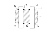
- the thermistor element manufactured by the powder press method has a large warp due to the outer periphery of the sintered body 1 being curved, and a break is formed at the insertion opening of the lead wire 2 which is a Pt wire. 1a may occur.
- the size of the cut 1a also causes variations in resistance value. That is, since the powder and the lead wire 2 are pressed at the same time, the powder and the lead wire 2 are in close contact with each other, and the shrinkage of the thermistor powder at the lead wire joint portion is suppressed during sintering, and the sintered body 1 is greatly warped. May occur.
- the present invention has been made in view of the above-described problems, and provides a method for manufacturing a thermistor element and a thermistor element that can suppress variations in resistance value with high dimensional accuracy and are less prone to cracks, cuts, or warpage. With the goal.
- the thermistor element manufacturing method of the present invention is a thermistor element manufacturing method comprising a thermistor metal oxide sintered body and a plurality of lead wires connected to the thermistor metal oxide sintered body.
- a step of forming a clay by mixing and kneading a thermistor raw material powder made of a metal oxide, an organic binder powder and a solvent, and a plurality of through-holes by extruding the clay with a molding die
- a molding die Forming a rod-shaped green molded body having a shape, drying the rod-shaped green molded body to form a rod-shaped dry molded body, and cutting the rod-shaped dry molded body into a predetermined length
- cutting the molded body into the thermistor metal oxide sintered body by inserting the lead wire into the through-hole of the cut molded body and firing in this state.
- a kneaded material obtained by kneading a thermistor raw material powder, an organic binder powder, and a solvent is extruded by a molding die to form a rod-shaped green molded body, and a cut molded body obtained by cutting the green molded body. Since the lead wire is inserted into the through-hole and fired, a clearance taking into account the thermistor contraction during sintering can be provided between the cut molded body and the lead wire, and the inner diameter of the through-hole is constant.
- the cut molded body and the lead wire are joined during sintering, and the contraction difference between the thermistor in the vicinity of the lead wire joint portion and the portion away from the lead joint portion is reduced. For this reason, warpage hardly occurs after firing, the metal oxide sintered body for the thermistor and the lead wire can be bonded uniformly and firmly, and a high temperature thermistor element resistant to heat cycle can be produced.
- the same shape can be obtained with a highly accurate dimension by adjusting the cutting length, it is possible to efficiently manufacture by suppressing resistance value variation due to dimensional variation.
- the organic binder powder is a water-soluble organic binder powder, and the solvent is water. That is, in this method for producing the thermistor element, the organic binder powder is a water-soluble organic binder powder, so that the kneaded material obtained by kneading the thermistor raw material powder, the water-soluble organic binder powder and water in the drying step is the thermistor.
- organic binder powder insoluble in water and organic solvent such as ethanol, toluene, etc., it is dried more slowly, so it is hard to crack.
- the method for producing the thermistor element of the present invention is characterized in that methylcellulose-based water-soluble organic binder powder is used as the water-soluble organic binder powder. That is, in this method for producing the thermistor element, a methylcellulose binder having a good compatibility with the metal oxide is used as the water-soluble organic binder powder, so that a kneaded material well kneaded with the thermistor raw material powder is obtained, and by extrusion molding. A good rod-shaped green molded body can be obtained.
- the method for producing a thermistor element of the present invention is characterized in that at least one of a plasticizer, a lubricant, a wetting material, or a wax is added to the organic binder powder.
- a plasticizer, a lubricant, a wetting material, or a wax is added to the organic binder powder, so that the powder is wetted with a solvent such as water. Property can be improved, and good extrusion molding becomes possible.
- the drying is preferably natural drying.
- the rod-shaped green molded body is dried with hot air using a heater, moisture drying unevenness is likely to occur, so cracks are likely to occur between the multiple through-holes, and the rod-shaped green molded body tends to be warped. It is easy to cause cracks. In addition, this warpage becomes an obstacle to fixing the molded body when it is subsequently cut.
- the method for manufacturing the thermistor element of the present invention since the rod-shaped green molded body is dried by natural drying to obtain a rod-shaped dry molded body, unevenness of moisture drying hardly occurs and the occurrence of cracks and warpage is also suppressed.
- the term “natural drying” as used herein means that the drying is performed at room temperature over a slow time (a time sufficient for drying). More preferably, drying is performed at a constant temperature and a constant humidity.
- the manufacturing method of the thermistor element of this invention forms one or more flat surfaces in the outer peripheral surface of the said rod-shaped dry molding body, It is characterized by the above-mentioned. That is, in this method of manufacturing the thermistor element, one or more flat surfaces are formed on the outer peripheral surface of the rod-shaped dry molded body, so that the rod-shaped dry molded body can be easily positioned by the flat surface during subsequent cutting.
- the diameter of the through hole of the cut molded body is larger than the diameter of the lead wire, and the firing is performed without inserting the lead wire into the through hole.
- the diameter is set to be smaller than the diameter of the lead wire. That is, in this method of manufacturing the thermistor element, the diameter of the through hole of the cut molded body is larger than the diameter of the lead wire, and when firing is performed without inserting the lead wire into the through hole, the diameter of the lead wire Since it is set to be small, the lead wire can be easily inserted into the through hole before firing, and the lead wire can be firmly joined by shrinkage of the through hole during firing.
- the method for manufacturing the thermistor element of the present invention at least one of the lead wires protruding from the through hole is before the firing and before or after the lead wire is inserted into the through hole of the cut molded body.
- a locking portion that is larger than the diameter of the through hole and bulges outward in the radial direction is formed. That is, in this method of manufacturing the thermistor element, the engaging portion bulging outward in the radial direction larger than the diameter of the through hole is formed on at least one of the lead wires protruding from the through hole by processing such as caulking.
- the locking portion can be positioned with a constant protrusion amount of the lead wire, and variation in the protrusion amount can be suppressed during firing.
- the method for producing the thermistor element of the present invention has a step of placing the cut molded body on a setter in a state where the lead wire is inserted into the through hole during the firing, and in the step, the setter In the installation hole or the installation groove having a diameter or width smaller than the outer diameter of the sintered metal oxide for thermistor formed on the outer diameter and larger than the diameter of the lead wire, The cut molded body is placed on the setter with the lower side of the lead wire inserted. Cutting the lead wire to make the lead wire protrusion constant after firing leads to loss of the lead wire and increases the number of processes, so the position of the lead wire is fixed at the time of firing. It is important to.
- the protrusion amount of the lead wire can be adjusted to be constant by digging a groove that can fix the lead wire and the cut molded body in the setter with the lead wire lying sideways.
- the diameter or width of the thermistor metal oxide sintered body formed on the setter is smaller than the outer diameter and larger than the lead wire diameter. Since the cut molded body is installed on the setter with the locking portion on the upper side and the lower side of the lead wire inserted into the hole or installation groove, the lead wire is suspended in the installation hole or installation groove.
- the lead wire can be fired with a constant protrusion amount. This eliminates the need to adjust the protruding amount of the lead wire after firing, and reduces the loss of the lead wire that is cut to make the length uniform.
- the thermistor element of the present invention is manufactured by the method for manufacturing the thermistor element of the present invention. That is, in this thermistor element, since it is manufactured by the method for manufacturing the thermistor element of the present invention, the occurrence of cracks, breaks or warpage is suppressed, and it has high reliability and the same shape with high dimensional accuracy. Thus, an element with little variation in resistance value and high uniformity of characteristics can be obtained.
- the present invention has the following effects. That is, according to the method for producing the thermistor element according to the present invention, a kneaded material obtained by kneading the thermistor raw material powder, the organic binder powder and the solvent is extruded by a mold for forming a rod-shaped green molded body, Since the lead wire is inserted into the through-hole of the cut molded body that has been cut and fired, warping is unlikely to occur after firing, and the metal oxide sintered body for the thermistor and the lead wire are bonded uniformly and firmly. Thus, a high temperature thermistor element that is resistant to heat cycle can be manufactured.
- the same shape can be obtained with a highly accurate dimension by adjusting the cutting length, it is possible to efficiently manufacture by suppressing resistance value variation due to dimensional variation. Therefore, according to the thermistor element manufactured by this manufacturing method, the occurrence of cracks, cuts or warpage is suppressed and high reliability is obtained, and the same shape is obtained with high dimensional accuracy, and resistance value variation is small. An element having high uniformity of characteristics can be obtained. In particular, it is suitable as a high-temperature measurement sensor that detects the catalyst temperature around the automobile engine and the exhaust system temperature.
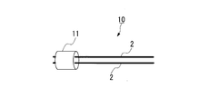
- FIG. 3 is a perspective view showing the thermistor element in the first embodiment of the thermistor element manufacturing method and the thermistor element according to the present invention.
- 1st Embodiment it is simple sectional drawing which shows the extrusion molding machine using the metal mold
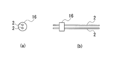
- 1st Embodiment it is the side view and front view which show a rod-shaped green molded object.
- 1st Embodiment it is the side view and front view which show the cutting molded object which inserted the lead wire.
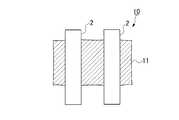
- FIG. 1 It is sectional drawing which shows a thermistor element in the manufacturing method of the thermistor element which concerns on this invention, and the prior art example (powder press product) of the thermistor element.
- the manufacturing method of the thermistor element concerning this invention, and the 2nd embodiment of the thermistor element it is a side view showing before and after caulking processing in the state where the lead wire was inserted in the cut molding.
- 2nd Embodiment in the state which inserted the lead wire in the cutting molding, it is a top view which shows before and after caulking process.
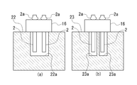
- 2nd Embodiment it is sectional drawing which shows the state which installed the cutting molding body by which the lead wire was inserted in the cutting molding body in the setter without a partition and the setter with a partition.
- FIGS. 1 to 5 a method for manufacturing a thermistor element and a first embodiment of the thermistor element according to the present invention will be described with reference to FIGS. 1 to 5.
- the thermistor element manufacturing method of the present embodiment includes a thermistor metal oxide sintered body 11 and a pair of lead wires 2 connected to the thermistor metal oxide sintered body 11.
- the metal oxide sintered body 11 for the thermistor a perovskite oxide mixed with an insulating material is used.
- the B constant which is a parameter indicating the electrical characteristics of the thermistor element 10, changes the x, y, z amount of (Y 1 ⁇ z La z ) 1 ⁇ y A y (Cr 1 ⁇ x Mn x ) O 3. Adjust by.
- the resistance value increases as the B constant decreases. Therefore, if the resistance cannot be adjusted by changing the shape, it is necessary to mix and sinter the insulator material to increase the resistance value.
- the insulator material is Y 2 O 3 , but this may be changed to another insulator material, for example, ZrO 2 , MgO, Al 2 O 3 , or CeO 2 .
- La 2 O 3 powder is heated and dried at 1000 ° C. for 2 hours, and the remaining hydroxide is regenerated into La 2 O 3 .
- the raw material preparation of La 2 O 3 is used within 2 to 3 hours after heating, or stored in a dry box for 2 to 3 days after heating.
- these powders of La 2 O 3 , Y 2 O 3 , CaCO 3 , SrCO 3 , Cr 2 O 3 and MnO 2 are weighed and placed in a ball mill, and Zr balls and ethanol are mixed in an appropriate amount for about 24 hours. I do.
- the mixture was taken out and dried, followed by firing at 1300 ° C. for 5 hours.
- the calcined powder and a new Y 2 O 3 powder are weighed, a sintering aid CaCO 3 is added, and pulverized with a ball mill using Zr balls and ethanol.
- a sintering aid CaCO 3 is added, and pulverized with a ball mill using Zr balls and ethanol.
- the calcined powder, Y 2 O 3 and CaCO 3 if La is not left alone in the calcined powder, it may be mixed and ground using pure water. The mixing time is about 24 hours, and then dried to obtain a thermistor raw material powder.
- the thermistor raw material powder made of the metal oxide, the organic binder powder, and the solvent are mixed and kneaded to form a clay.
- the organic binder powder a binder that is generally used for extrusion molding and that exhibits high viscosity in a low concentration aqueous solution is used.
- water-soluble organic binder powder is preferable, and examples thereof include methyl cellulose (commonly called MC), ethyl cellulose (EC), polyvinyl alcohol (PVA), polyethylene glycol (PEG), polyethylene oxide (PEO), and the like.
- water is used as the solvent.
- a methylcellulose type is often used, and examples thereof include carboxymethylcellulose (CMC), hydroxybutylmethylcellulose (HBMC), and hydroxypropylmethylcellulose (HPMC).
- CMC carboxymethylcellulose
- HBMC hydroxybutylmethylcellulose
- HPMC hydroxypropylmethylcellulose
- EHEC ethyl hydroxyethyl cellulose
- a plasticizer, a lubricant, a wetting material or a wax is added to these organic binder powders.
- a methyl cellulose (MC) system is adopted as the water-soluble organic binder powder, and a plasticizer, a lubricant, a wetting material, etc. are added to this as pure water and additives, and the mixture is mixed with a mixer.
- a peptizer, a dispersant, a water retention agent, a surfactant, a curing agent, etc. may be added as a molding aid.
- the above-mentioned wet powder containing the water-soluble organic binder is mixed and kneaded using a screw of a raw material kneader to form a clay-like clay.
- the kneading is repeated.
- the clay is put into the extruder 12 and mixed and kneaded while evacuating using a screw (not shown). By kneading while evacuating, bubbles can be prevented from entering the molded body. In addition, if the mixing and kneading is not sufficiently performed, the stability and accuracy of extrusion molding deteriorate. Further, the clay is pressed and squeezed using a screw and extruded through a molding die 13 to form a rod-shaped green molded body 15 having a pair of through holes 14 as shown in FIG. .
- the extrusion molding machine 12 has a structure in which a mixture kneaded while being evacuated can be extruded as it is. Further, as shown in FIG. 2, the molding die 13 is a two-hole molding die, and has a plurality of extrusion holes 13b for extruding clay into a cylindrical hollow mold 13a and a pair. In order to form the through-hole 14, a pair of swine nose bars 13c extending along the axis in the mold 13a is provided.
- a rod-shaped green molding 15 having a diameter of 2.0 mm and a diameter of the through hole 14 (pig nose diameter) of 0.34 mm is formed.
- the extrusion molding it is important to keep the extrusion pressure constant and keep the extrusion speed constant. If the amounts of the water-soluble organic binder powder and water are not appropriate, cracks may occur in the rod-shaped green molded body 15. For example, if the amount of water is too much or too little, even extrusion molding cannot be performed, and the molded body may not come out of the molded body mold 13. Further, even if the molded body comes out, the shape such as the diameter may vary, which causes the resistance value variation of the thermistor element 10 after firing.
- the rod-shaped green molded body 15 is naturally dried in order to suppress warping due to drying shrinkage.
- natural drying is preferable. This is because when drying with hot air using a heater, unevenness in moisture drying is likely to occur, so that cracks are likely to occur between the pair of through holes 14.
- the rod-shaped green molded body 15 is likely to be greatly warped and cracks due to the warpage are prevented. This warpage becomes an obstacle to fixing the rod-shaped green molded body 15 when it is cut thereafter.
- the rod-shaped green molded body 15 is slowly dried for 1 to 2 days in a box having a constant temperature and a constant humidity.
- this moisture drying is performed, moisture is released and the rod-shaped green molded body 15 contracts. Since both the outer diameter of the rod-shaped green molded body 15 and the diameter of the through hole 14 (pig nose diameter) contract, the mold 13 for molded body must be designed in consideration of this moisture contraction.
- the rod-shaped dry molded body is cut into a predetermined length to obtain a cut molded body 16 having a through hole 14 in a pig nose shape. That is, this rod-shaped dry molding is fixed and cut by dicing.
- the rod-shaped dry molded body is cut at an accuracy of 1.00 mm ⁇ 0.02 mm every 1.00 mm. By cutting with this accuracy, the initial resistance error can be suppressed to within 2% after firing.
- the cutting method may be performed by press cutting. However, if the rod-shaped dry molded body is too hard, the blade is chipped at the time of cutting. Therefore, in the case of press-cut cutting, it is necessary to reduce the hardness of the rod-shaped dry molded body.
- the round bar-shaped lead wire 2 is inserted into the pair of through holes 14 of the cut molded body 16 and penetrated.
- a metal wire having a high melting point of 1400 ° C. or higher such as a Pt wire, a wire containing Rh in Pt, a wire containing Ir in Pt, or the like is adopted.
- the cut molded body 16 in a state where the lead wire 2 is inserted into the through hole 14 is subjected to binder removal treatment, and then fired at about 1500 ° C. to obtain the metal oxide sintered body 11 for the thermistor. Element 10 was produced.
- the diameter of the through hole 14 of the rod-shaped green molded body 15 is set so as to be larger than the diameter of the lead wire 2 in consideration of insertability when dried to form a rod-shaped dry molded body. . Further, the diameter of the through hole 14 of the rod-shaped dry molded body and the cut molded body 16 is set to be smaller after firing than the diameter of the lead wire 2 in consideration of the bondability due to shrinkage during sintering.
- the shrinkage rate due to the sintering is obtained by dividing the through hole diameter of the cut molded body 16 by subtracting the through hole diameter after firing without inserting the lead wire into the through hole.
- the kneaded material obtained by kneading the thermistor raw material powder, the organic binder powder, and water (solvent) is extruded by the molding die 13 to form the rod-shaped green molded body 15. Since the lead wire 2 is inserted into the through-hole 14 of the cut molded body 16 that has been cut and fired, the thermistor shrinkage during sintering is considered between the cut molded body 16 and the lead wire 2.
- the through hole 14 has a constant inner diameter
- the cut molded body 16 and the lead wire 2 are joined to each other during the sintering, and there is almost no difference due to the thermistor contraction in the vicinity of the joint portion of the lead wire 2. No.
- warp and cut 1a are not easily generated after firing, and the metal oxide sintered body 11 for the thermistor and the lead wire 2 can be uniformly and firmly joined, and are resistant to heat cycle.
- a high temperature thermistor element can be produced.
- the same shape can be obtained with a highly accurate dimension by adjusting the cutting length of the cut molded body 16, it is possible to efficiently manufacture by suppressing resistance value variation due to dimensional variation.
- the organic binder powder is a water-soluble organic binder powder
- the clay obtained by kneading the thermistor raw material powder the water-soluble organic binder powder and water in the drying step is insoluble in the thermistor raw material powder and water.
- an organic solvent such as ethanol and toluene
- a methyl cellulose (MC) binder that has a good compatibility with metal oxides is used, so that a kneaded clay well mixed with the thermistor raw material powder is obtained, and a good rod-shaped green is obtained by extrusion molding.
- a molded body 15 can be obtained.
- the rod-shaped green molded body 15 is dried by natural drying to obtain a rod-shaped dry molded body, unevenness in moisture drying hardly occurs, and generation of cracks and warpage is also suppressed.
- the diameter of the through hole 14 of the cut molded body 16 is set to be larger than the diameter of the lead wire 2 in consideration of insertability when dried into a rod-shaped dry molded body,
- the diameter of the through hole 14 of the cut molded body 16 is set to be smaller after firing than the diameter of the lead wire 2 in consideration of the bondability due to shrinkage during sintering, so that the metal oxide sintered body for the thermistor 11 and the lead wire 2 can be joined, and the thermistor element 10 can be manufactured.
- the difference between the second embodiment and the first embodiment is that in the first embodiment, the cut molded body 16 into which the straight rod-like lead wire 2 is inserted is fired, whereas in the second embodiment, FIG. As shown in FIG. 8 and before firing, before or after inserting the lead wire 2 into the through hole 14 of the cut molded body 16, the through hole 2 is formed in at least one of the lead wires 2 protruding from the through hole 14. The locking portion 2a bulging outward in the radial direction larger than the diameter is formed.
- the stop 2a is formed by processing such as caulking. Then, the lead wire 2 is inserted into the through hole 2 from the end where the locking portion 2a is not formed.
- the locking portion 2 a bulging outward in the radial direction larger than the diameter of the through hole 2 is provided on one or both of the lead wires 2 protruding from the through hole 14. It is formed by processing such as caulking.
- the locking portion 2a is formed by inserting a blade 21 into a predetermined position of the lead wire 2 from both sides and locally crushing the side portion. 7 (b), the locking portion 2a is formed by inflating in a direction perpendicular to the crushing direction.
- the protruding amount of the lead wire 2 is preferably as small as possible. For example, it is preferable to suppress the protrusion amount within 0.3 mm with respect to the cut molded body 16 having a thickness of 1.0 mm. As a result, the metal oxide sintered body 11 for the thermistor can be provided on the sensor tip side without causing an electrical short circuit.
- 2nd Embodiment As shown to (a) of FIG. 9, it has the process of installing the cutting molded body 16 in the setter 22 in the state which inserted the lead wire 2 in the through-hole 14 in the case of baking.
- the metal oxide sintered body 11 for the thermistor after firing formed in the setter 22 is smaller than the outer diameter, and is locked in the installation groove 22a having a width into which the pair of lead wires 2 can be inserted.
- the cut molded body 16 is placed on the setter 22 with the portion 2a facing upward and the lower side of the lead wire 2 being inserted.
- the size of the installation groove 22a is set smaller than the outer diameter of the sintered body in consideration of shrinkage during sintering, and is set larger than the diameter of the lead wire 2 in order to insert the lead wire 2. .
- the size of the installation groove 22a is set smaller than the outer diameter of 11.
- the reason for this setting is that if the size of the installation groove 22 is set larger than the outer diameter of the metal oxide sintered body 11 for the thermistor, the cut molded body 16 falls into the installation groove 22 and leads This is because the line 2 may come off.
- the setter 22 is made of alumina, for example.
- the installation groove 22a is formed in a slit shape in which a plurality of cut molded bodies 16 can be installed side by side.
- the locking portion 2a bulging outward in the radial direction larger than the diameter of the through hole 14 is formed on at least one of the lead wires 2 protruding from the through hole 14 by processing such as caulking.
- the lead wire 2 is locked by the locking portion 2a when the cut molded body 16 in which the lead wire 2 is inserted is gripped and lifted with the locking portion 2a on the upper side. It is possible to prevent the line 2 from coming off. Further, the locking portion 2a can be positioned with the protrusion amount of the lead wire 2 kept constant, and variations in the protrusion amount during firing can be suppressed.
- the thermistor element when the thermistor element is incorporated in the sensor, it is possible to prevent the occurrence of an electrical short circuit, and it is possible to prevent the occurrence of a change in welding conditions due to a change in the welding position when welding with the SUS wire in the sensor.
- a soft Pt wire as the lead wire 2, it is easy to process such as caulking for forming the locking portion 2a.
- the lower side of the lead wire 2 was inserted into the installation groove 22a having a width smaller than the outer diameter of the sintered metal oxide sintered body 11 for thermistor formed on the setter 22 with the engaging portion 2a on the upper side.
- the cut molded body 16 is installed on the setter 22, so that the lead wire 2 is suspended in the installation groove 22a, so that the protruding amount of the lead wire 2 is constant regardless of the warp of the setter 22, etc. Can be fired in line. This eliminates the need for adjusting the protruding amount of the lead wire 2 after firing, and reduces the loss of the lead wire 2 that is cut to make the lengths uniform.
- the installation groove 22a of the setter 22 has no partition between the pair of inserted lead wires 2, but a partition is provided between the pair of lead wires 2 as shown in FIG. 9B.
- the setter 23 having the installation hole 23a may be adopted.
- the setter 23 for example, a hollow setter 23 using honeycomb ceramics or the like can be used.
- the evaluation results of the thermistor element actually manufactured by the method for manufacturing the thermistor element of the first embodiment are shown below.
- a heat resistance test was performed at 1000 ° C. for 100 hours on the thermistor element after firing. As a result of this heat resistance test, it was confirmed that the electrical resistivity change rate was within 1% in the examples of the present invention as in the case of the powder press product.
- the thermistor element after firing was subjected to a heat cycle test (HCT), and the presence or absence of a resistance value increase rate of 2% due to the occurrence of cracks was examined.
- the conditions for this heat cycle test (HCT) were 100 cycles with room temperature and 1000 ° C. alternated.
- a Pt wire (lead wire 2) having a diameter of 0.20 to 0.31 mm is used for a rod-shaped dry molded body having a diameter of 1.85 mm ⁇ 1.0 mm and a diameter of the through hole 14 (pig nose diameter) of 0.32 mm. ) (Length of about 1 mm) was inserted. The results are shown in Table 1.
- the thermistor element obtained by the powder press method was a sample in which the resistance value increased after the heat cycle.
- the shrinkage ratio due to sintering of the thermistor element of the above embodiment was 19%, and when ⁇ L was 0.04 mm or more, an increase in resistance value due to heat cycle was suppressed.
- variation in a rod was investigated.
- the results are also shown in Table 1 above.
- the resistance value variation 3 ⁇ / ⁇ of the thermistor element obtained in this embodiment was 1 to 2%.
- ⁇ is a standard deviation of the resistance value in the rod
- ⁇ is an average value of the resistance value in the rod. It is possible to manufacture the semiconductor device while suppressing variation in cutting dimensions within 1 to 2%, and as a result, suppressing variation in resistance value.
- 3 ⁇ / ⁇ obtained by the powder pressing method as a comparative example was 8 to 10%. Although weighed the raw materials within 1%, the variation in resistance value in the rod increased due to variations in powder filling during pressing, flashing, insufficient press pressure near the lead wire, etc. End up. These causes are difficult to avoid in the manufacturing method.
- the rod-shaped dry molded body has a cylindrical shape, but one or more flat surfaces may be formed on the outer peripheral surface of the rod-shaped dry molded body.
- the shape in the mold is set so that a flat surface is formed on the outer peripheral surface of the rod-shaped green molded body during extrusion molding.
- the rod-shaped dry molded body can be easily positioned by the flat surface during subsequent cutting.
Landscapes
- Engineering & Computer Science (AREA)
- Chemical & Material Sciences (AREA)
- Ceramic Engineering (AREA)
- Microelectronics & Electronic Packaging (AREA)
- Structural Engineering (AREA)
- Materials Engineering (AREA)
- Manufacturing & Machinery (AREA)
- Organic Chemistry (AREA)
- Physics & Mathematics (AREA)
- Electromagnetism (AREA)
- Inorganic Chemistry (AREA)
- Thermistors And Varistors (AREA)
- Apparatuses And Processes For Manufacturing Resistors (AREA)
Abstract
Description
従来、Pt線を埋め込んだ高温サーミスタの製造方法として、例えば特許文献1に記載されているように、金属線をセラミックス造粒粉と同時にプレスする粉末プレス法が用いられてきた。
サーミスタ素子を使うにあたって、温度検出誤差を抑えるためには、抵抗値のばらつきを抑えることが必須であるが、このばらつきの主要因としては、素子(焼結体)と電極(Pt線)との接触面積及び電極(Pt線)間の長さのばらつきが挙げられる。特に、前者の接触面積のばらつき、つまり造粒粉の量のばらつきに抵抗値ばらつきが強く依存する。
近年、センサの応答性の要求から、サーミスタ素子の小型化が要請されており、例えば素子(焼結体)の大きさで、2mm径×1mm厚さ程度であって、その際に使用する造粒粉の量は数mgとされる。この場合、一定量の粉末を計量により金型に充填する方法では、微小量の計量となるため、高精度で効率よく計量するのが難しい。例えば、造粒粉の量が10mgの場合、抵抗値ばらつきを1%に抑えるためには、0.1mgの秤量精度が必要であるが、天秤を用いて高精度で効率よく計量し、さらに、その計量した粉を、例えば2mm径の穴の開いた金型にこぼすことなく、効率よく入れることは、大変困難である。
また、金型に粉を入れた状態ですり切りにより一定量とする方法では、粉末の充填状態のばらつきにより粉末の量が変化し、プレス後の厚みが変化してしまう不都合があった。
さらに、粉末の金型への充填が十分でない場合には、プレス時にPt線の変形が起き、プレス金型のPt線挿入部へ粉末が入りこみ(ばりの発生)、抵抗値ばらつきの原因となる問題があった。
すなわち、粉末とリード線2とを同時にプレスするため、粉末とリード線2とが密着しており、焼結時にリード線接合部のサーミスタ粉末の収縮が抑えられて、焼結体1に大きな反りが生じる場合があった。
また、リード線2の挿入口近傍では、リード線2とプレス用金型との間に取り出しのためのクリアランスが存在するため、リード線2の挿入口近傍には圧力が十分にかからない。そのため、このまま焼結させると、リード線2の挿入口近傍に切れ目1aが生じてしまい、この切れ目1aが上記反りを助長していると考えられる。
このように、初期状態で焼結体1の反りと挿入口の切れ目1aとがあると、焼結体1とリード線2との熱膨張差があるため、ヒートサイクル(室温と1000℃との間で100回以上)により焼結体1とリード線2との間の接合の破壊が進んでクラックが大きくなり、抵抗値が大きくなってしまうことから、信頼性不十分の要因となる不都合があった。
また、切断長を調整することにより高精度な寸法で同一形状が得られるので、寸法ばらつきによる抵抗値ばらつきを抑えて、効率よく作製することができる。
すなわち、このサーミスタ素子の製造方法では、有機バインダー粉が、水溶性有機バインダー粉であるので、上記乾燥の工程で、サーミスタ原料粉末と水溶性有機バインダー粉と水とを混練した坏土が、サーミスタ原料粉末と水に対して不溶性の有機バインダー粉とエタノール、トルエン等の有機溶剤とを混練した坏土に比べて、ゆっくり乾燥されるため、クラックが入りにくい。
すなわち、このサーミスタ素子の製造方法では、水溶性有機バインダー粉として、金属酸化物との相性が良いメチルセルロース系バインダーを使用するので、サーミスタ原料粉末と良く混練された坏土が得られ、押出成型によって良好なロッド状グリーン成型体を得ることができる。
押出成型の際、粉末間の摩擦が多い、若しくは粉末と水等の溶剤との濡れ性が無いと、押出表面が滑らかにならず、表面欠陥が増えたり、坏土の結合性が乏しくなるため、クラックが生じやすくなるが、本発明のサーミスタ素子の製造方法では、有機バインダー粉に、可塑剤、潤滑剤、湿潤材又はワックスの少なくとも1種を加えるので、粉末と水等の溶剤との濡れ性を向上させることができ、良好な押出成型が可能になる。
ロッド状グリーン成型体を、ヒーターを用いて熱風乾燥させると、水分乾燥のむらが生じやすいため、複数の貫通孔間にクラックが入りやすいと共に、ロッド状グリーン成型体に大きな反りが生じやすく、この反りによるクラックも生じやすくなる。また、この反りは、その後切断する際の成型体固定の障害ともなる。しかしながら、本発明のサーミスタ素子の製造方法では、自然乾燥でロッド状グリーン成型体を乾燥させてロッド状乾燥成型体とするので、水分乾燥のむらが生じにくく、クラックや反りの発生も抑制される。なお、ここで自然乾燥とは、室温で乾燥にゆっくり時間(乾燥に十分な時間)をかけて乾燥させる意味である。より好ましくは、一定温度、一定湿度で乾燥させることが良い。
すなわち、このサーミスタ素子の製造方法では、ロッド状乾燥成型体の外周面に平坦面を1箇所以上形成するので、その後の切断時に平坦面によりロッド状乾燥成型体の位置決めがしやすくなる。
すなわち、このサーミスタ素子の製造方法では、切断成型体の貫通孔の径が、リード線の径よりも大きく、かつリード線を貫通孔に挿入せずに焼成を行った場合にリード線の径より小さくなるように設定されているので、焼成前にリード線を容易に貫通孔に挿入できると共に焼成の際に貫通孔の収縮によってリード線を強固に接合させることができる。
すなわち、このサーミスタ素子の製造方法では、貫通孔から突出するリード線の少なくとも一方に貫通孔の径よりも大きく半径方向外方に膨出した係止部をかしめ等の加工によって形成しておくので、係止部を上側にしてリード線が挿入された状態の切断成型体を掴んで持ち上げた際に、係止部でリード線が係止されることで、リード線が抜けることを防止できる。また、係止部によってリード線の突出量を一定にして位置決めをすることができ、焼成時に突出量のばらつきを抑制することが可能になる。これにより、サーミスタ素子をセンサに組み込む際に、電気短絡の発生を防ぐことができると共に、センサ内SUS線と溶接する際に、溶接位置が変わることによる溶接条件変化の発生を防ぐことができる。なお、リード線として柔らかいPt線を採用することで、上記係止部を形成するためのかしめ等の加工がしやすい。
焼成後にリード線の突出量を一定にするためにリード線を切断加工することは、リード線のロスがあると共に工程の増加を招くことから、焼成時において、リード線の位置を一定にして固定することが重要である。例えば、リード線を横にしてセッターにリード線と切断成型体とを固定できる溝を掘っておくことで、リード線の突出量を一定に調整可能である。しかしながら、焼成を繰り返すとセッターの反りが発生するために、常に同じ突出量で焼成できるとは限らない。この対策として、本発明のサーミスタ素子の製造方法では、セッターに形成された焼成後のサーミスタ用金属酸化物焼結体の外径よりも小さく、かつ、リード線の径より大きい径又は幅の設置孔又は設置溝に、係止部を上側にしてリード線の下側を差し込んだ状態で、切断成型体をセッター上に設置するので、リード線が設置孔又は設置溝の中で宙吊り状態となることで、セッターの反り等に関係なく、リード線の突出量を一定に揃えて焼成することができる。これにより、焼成後にリード線の突出量を調整する加工が不要になると共に、長さを揃えるために切断するリード線のロスが少なくて済む。
すなわち、本発明に係るサーミスタ素子の製造方法によれば、サーミスタ原料粉末と有機バインダー粉と溶剤とを混練した坏土を成型体用金型によって押出成型してロッド状グリーン成型体を形成し、これを切断した切断成型体の貫通孔にリード線を挿入して焼成を行うので、焼成後に反りが生じ難いと共に、サーミスタ用金属酸化物焼結体とリード線とを均一かつ強固に接合することができ、ヒートサイクルに強い高温サーミスタ素子を作製することができる。また、切断長を調整することにより高精度な寸法で同一形状が得られるので、寸法ばらつきによる抵抗値ばらつきを抑えて、効率よく作製することができる。したがって、この製法で作製されたサーミスタ素子によれば、クラック、切れ目又は反りの発生が抑制されて高い信頼性を有していると共に、高い寸法精度で同一形状が得られ、抵抗値ばらつきが少なく特性の均一性が高い素子が得られる。特に、自動車エンジン周りの触媒温度や排気系温度を検出する高温測定用センサとして好適である。
サーミスタ用金属酸化物焼結体11としては、ペロブスカイト型酸化物に絶縁体材料を混合焼結したものが使用される。例えば、一般式:1-w(La1-zYz)1-yAy(Cr1-xMnx)O3+wY2O3(ただし、A=Ca,Sr 0.0≦x≦1.0、0.0≦y≦1.0、0.0≦z≦1.0、0≦w≦0.9)で示される複合酸化物を含む焼結体で構成されている。
次に、これらLa2O3、Y2O3、CaCO3,SrCO3,Cr2O3及びMnO2の各粉末を秤量後にボールミルに入れ、Zrボールとエタノールとを適量入れて約24時間混合を行う。この混合したものを取り出して乾燥させた後、1300℃、5時間にて焼成し、例えば、上記一般式においてx=0.4,y=0,z=0.5とされた(La0.5Y0.5)(Cr0.6Mn0.4)O3の仮焼粉を得る。
上記有機バインダー粉としては、一般に押出成型に用いられるバインダーであって、低濃度水溶液で高粘性を示すものが用いられる。特に、水溶性有機バインダー粉が好ましく、例えば、メチルセルロース系(通称MC)、エチルセルロース系(EC)、ポリビニルアルコール(PVA)、ポリエチレングリコール(PEG)、ポリエチレンオキサイド(PEO)等がある。また、溶剤としては、水が用いられる。
なお、その他、エチルセルロース系では、エチルヒドロキシエチルセルロース(EHEC)が使われる。
本実施形態では、例えば水溶性有機バインダー粉としてメチルセルロース(MC)系を採用し、これに純水と添加剤として可塑剤、潤滑剤、湿潤材等を加えてミキサーで混合し、水溶性有機バインダー入り湿粉とする。なお、さらに成型助剤として、他に解膠剤、分散剤、水分保持剤、界面活性剤、硬化剤等を添加しても構わない。
なお、上記押出成型の際、押出成型圧力を一定にし、押出成型スピードを一定に保つことが重要である。水溶性有機バインダー粉及び水の量が適当な量でないと、ロッド状グリーン成型体15にクラックが生じる場合がある。例えば、水分量が多すぎる若しくは少なすぎると押出成型すらできず、成型体用金型13から成型体が出てこないことがある。また、成型体が出てきたとしても、径がばらつく等の形状が変わることもあり、これは焼成後、サーミスタ素子10の抵抗値ばらつきの要因となる。
なお、ロッド状グリーン成型体15を水分乾燥する際、自然乾燥が好ましい。ヒーターを用いて熱風乾燥させると、水分乾燥のむらが生じやすいため、一対の貫通孔14間にクラックが入りやすいためである。また、ロッド状グリーン成型体15に大きな反りが生じやすくなり、その反りによるクラックが生じることを防ぐためである。なお、この反りは、その後切断する際のロッド状グリーン成型体15固定の障害となる。
この水分乾燥を行うと、水分が抜け、ロッド状グリーン成型体15の収縮が起きる。ロッド状グリーン成型体15の外周径及び貫通孔14の径(豚鼻径)が共に収縮するため、この水分収縮を考慮し、成型体用金型13を設計しなければならない。
すなわち、このロッド状乾燥成型体を固定し、ダイシングによる切断を行う。
例えば、ロッド状乾燥成型体を1.00mm毎、1.00mm±0.02mmの精度で切断する。この精度で切断することにより、焼成後、初期抵抗値誤差を2%以内に抑えることができる。
なお、切断方法については、押切切断で行ってもよい。ただし、ロッド状乾燥成型体があまりに硬いと切断時に刃が欠けてしまうので、押切切断の場合はロッド状乾燥成型体の硬度を下げる必要がある。
上記リード線2としては、1400℃以上の高融点を有する金属線であって、Pt線又はPtにRhが含有されている線、PtにIrが含有されている線等が採用される。
なお、ロッド状グリーン成型体15の貫通孔14の径は、乾燥させてロッド状乾燥成型体となった際に、挿入性を考慮してリード線2の径よりも大きくなるように設定される。
また、ロッド状乾燥成型体及び切断成型体16の貫通孔14の径は、焼結時の収縮による接合性を考慮してリード線2の径よりも焼成後に小さくなるように設定される。
ΔL=リード線径(mm)-(1-収縮率)×切断成型体の貫通孔径(mm)
また、有機バインダー粉が、水溶性有機バインダー粉であるので、上記乾燥の工程で、サーミスタ原料粉末と水溶性有機バインダー粉と水とを混練した坏土が、サーミスタ原料粉末と水に対して不溶性の有機バインダー粉とエタノール、トルエン等の有機溶剤とを混練した坏土に比べて、ゆっくり乾燥されるため、クラックが入りにくい。
特に、水溶性有機バインダー粉として、金属酸化物との相性が良いメチルセルロース(MC)系バインダーを使用するので、サーミスタ原料粉末と良く混練された坏土が得られ、押出成型によって良好なロッド状グリーン成型体15を得ることができる。
また、自然乾燥でロッド状グリーン成型体15を乾燥させてロッド状乾燥成型体とするので、水分乾燥のむらが生じにくく、クラックや反りの発生も抑制される。
また、貫通孔14にリード線2を挿入した後では、貫通孔14から突出するリード線2の一方又は両方に貫通孔2の径よりも大きく半径方向外方に膨出した係止部2aをかしめ等の加工によって形成する。
なお、リード線2の突出量はなるべく小さい方が良い。例えば、1.0mm厚の切断成型体16に対して、0.3mm以内に突出量を抑えることが好ましい。これにより、サーミスタ用金属酸化物焼結体11を、よりセンサ先端側に電気短絡させることなく備え付けることが可能になる。
なお、設置溝22aの大きさは、焼結時の収縮を考慮し、焼結体の外径よりも小さく設定され、リード線2を挿入するため、リード線2の径より大きく設定されている。図9にあるように、スリット(溝)の方向に対し、1対のリード線2が並ぶように、設置溝22aの大きさを調整した場合であっても、サーミスタ用金属酸化物焼結体11の外径よりも小さく設置溝22の大きさが設定されていればよい。このように設定した理由は、もし、設置溝22の大きさがサーミスタ用金属酸化物焼結体11の外径よりも大きく設定されると、切断成型体16が設置溝22に落下し、リード線2が抜ける可能性があるためである。
なお、上記セッター22は、例えばアルミナで形成されている。また、設置溝22aは、複数の切断成型体16を並べて設置可能なスリット状に形成されている。
また、スリット状の溝ではなく、焼結体の外径よりも小さく、かつ、1対のリード線2が挿入できる径より大きい円状の溝を採用しても構わない。
まず、焼成後にサーミスタ素子について、1000℃、100hで耐熱性試験を行った。この耐熱性試験の結果、粉末プレス品同様に、本発明の実施例では、電気抵抗率変化率が1%以内であることを確認した。
なお、このヒートサイクル試験(HCT)の条件は、室温と1000℃とを交互にして100サイクルとした。また、1.85mm径×1.0mm厚さ、貫通孔14の径(豚鼻径)0.32mmのロッド状乾燥成型体に対し、0.20~0.31mm径のPt線(リード線2)(長さ1mm程度)を挿入した。この結果を、表1に示す。

上記実施形態のサーミスタ素子の焼結による収縮率は19%であり、ΔLが0.04mm以上のとき、ヒートサイクルによる抵抗値上昇を抑えられた。
一方、比較例として粉末プレス法で得られた3σ/μは、8~10%であった。原料秤量を1%以内に抑えて実施したが、プレス時の粉末の充填状態のばらつき、ばりの発生、リード線近傍へのプレス圧力不十分等の原因で、ロッド内の抵抗値ばらつきは大きくなってしまう。これらの原因は、製造方法上、避けることが困難である。
Claims (10)
- サーミスタ用金属酸化物焼結体と、該サーミスタ用金属酸化物焼結体に接続された複数のリード線と、を有するサーミスタ素子の製造方法であって、
金属酸化物からなるサーミスタ原料粉末と有機バインダー粉と溶剤とを混合して混練することで坏土とする工程と、
成型体用金型によって前記坏土を押出成型して複数の貫通孔を有したロッド状グリーン成型体を形成する工程と、
前記ロッド状グリーン成型体を乾燥させてロッド状乾燥成型体とする工程と、
前記ロッド状乾燥成型体を所定長さに切断して貫通孔を有する切断成型体とする工程と、
前記切断成型体の前記貫通孔に前記リード線を挿入してこの状態で焼成を行うことで、
前記切断成型体を前記サーミスタ用金属酸化物焼結体とする工程と、を有していることを特徴とするサーミスタ素子の製造方法。 - 請求項1に記載のサーミスタ素子の製造方法において、
前記有機バインダー粉が、水溶性有機バインダー粉であり、前記溶剤が、水であることを特徴とするサーミスタ素子の製造方法。 - 請求項2に記載のサーミスタ素子の製造方法において、
前記水溶性有機バインダー粉として、メチルセルロース系の水溶性有機バインダー粉を使用することを特徴とするサーミスタ素子の製造方法。 - 請求項1に記載のサーミスタ素子の製造方法において、
前記有機バインダー粉に、可塑剤、潤滑剤、湿潤材又はワックスの少なくとも1種を加えることを特徴とするサーミスタ素子の製造方法。 - 請求項1に記載のサーミスタ素子の製造方法において、
前記乾燥が、自然乾燥であることを特徴とするサーミスタ素子の製造方法。 - 請求項1に記載のサーミスタ素子の製造方法において、
前記ロッド状乾燥成型体の外周面に平坦面を1箇所以上形成することを特徴とするサーミスタ素子の製造方法。 - 請求項1に記載のサーミスタ素子の製造方法において、
前記切断成型体の貫通孔の径が、前記リード線の径よりも大きく、かつ前記リード線を前記貫通孔に挿入せずに前記焼成を行った場合に前記リード線の径より小さくなるように設定されていることを特徴とするサーミスタ素子の製造方法。 - 請求項1から7のいずれか一項に記載のサーミスタ素子の製造方法において、
前記焼成の前であって、前記切断成型体の貫通孔に前記リード線を挿入する前又は後に、前記貫通孔から突出する前記リード線の少なくとも一方に前記貫通孔の径よりも大きく半径方向外方に膨出した係止部を形成しておくことを特徴とするサーミスタ素子の製造方法。 - 請求項8に記載のサーミスタ素子の製造方法において、
前記焼成の際に、前記貫通孔に前記リード線を挿入した状態で前記切断成型体をセッターに設置する工程を有し、
該工程において、前記セッターに形成された焼成後の前記サーミスタ用金属酸化物焼結体の外径よりも小さく、かつ、前記リード線の径より大きい径又は幅の設置孔又は設置溝に、前記係止部を上側にして前記リード線の下側を差し込んだ状態で、前記切断成型体を前記セッター上に設置することを特徴とするサーミスタ素子の製造方法。 - 請求項1に記載のサーミスタ素子の製造方法により作製されたことを特徴とするサーミスタ素子。
Priority Applications (2)
| Application Number | Priority Date | Filing Date | Title |
|---|---|---|---|
| CN2009801387983A CN102171774B (zh) | 2008-10-03 | 2009-07-27 | 热敏电阻元件的制造方法和热敏电阻元件 |
| US13/120,804 US8607440B2 (en) | 2008-10-03 | 2009-07-27 | Method of manufacturing a thermistor element |
Applications Claiming Priority (4)
| Application Number | Priority Date | Filing Date | Title |
|---|---|---|---|
| JP2008258742 | 2008-10-03 | ||
| JP2008-258742 | 2008-10-03 | ||
| JP2009064824A JP5267868B2 (ja) | 2008-10-03 | 2009-03-17 | サーミスタ素子の製造方法 |
| JP2009-064824 | 2009-03-17 |
Publications (1)
| Publication Number | Publication Date |
|---|---|
| WO2010038342A1 true WO2010038342A1 (ja) | 2010-04-08 |
Family
ID=42073131
Family Applications (1)
| Application Number | Title | Priority Date | Filing Date |
|---|---|---|---|
| PCT/JP2009/003516 Ceased WO2010038342A1 (ja) | 2008-10-03 | 2009-07-27 | サーミスタ素子の製造方法及びサーミスタ素子 |
Country Status (4)
| Country | Link |
|---|---|
| US (1) | US8607440B2 (ja) |
| JP (1) | JP5267868B2 (ja) |
| CN (1) | CN102171774B (ja) |
| WO (1) | WO2010038342A1 (ja) |
Cited By (1)
| Publication number | Priority date | Publication date | Assignee | Title |
|---|---|---|---|---|
| WO2020090309A1 (ja) * | 2018-10-30 | 2020-05-07 | 株式会社芝浦電子 | サーミスタ焼結体および温度センサ素子 |
Families Citing this family (2)
| Publication number | Priority date | Publication date | Assignee | Title |
|---|---|---|---|---|
| CN107146665A (zh) * | 2017-05-09 | 2017-09-08 | 句容市博远电子有限公司 | 一种低温烧结电阻元件及其制备方法 |
| JP7421840B2 (ja) * | 2019-02-08 | 2024-01-25 | 古河電気工業株式会社 | 光モジュール |
Citations (4)
| Publication number | Priority date | Publication date | Assignee | Title |
|---|---|---|---|---|
| JPH07235405A (ja) * | 1993-12-27 | 1995-09-05 | Komatsu Ltd | サーミスタ焼結体 |
| JPH0831621A (ja) * | 1994-07-19 | 1996-02-02 | Fujitsu Ltd | 厚膜抵抗体及び厚膜抵抗体の抵抗値調整方法 |
| JPH118103A (ja) * | 1997-06-13 | 1999-01-12 | Nippon Soken Inc | ワイドレンジ型サーミスタ素子 |
| JP2000012308A (ja) * | 1998-04-24 | 2000-01-14 | Nippon Soken Inc | サ―ミスタ素子の製造方法 |
Family Cites Families (16)
| Publication number | Priority date | Publication date | Assignee | Title |
|---|---|---|---|---|
| US4200970A (en) * | 1977-04-14 | 1980-05-06 | Milton Schonberger | Method of adjusting resistance of a thermistor |
| JPH0329388A (ja) * | 1989-06-26 | 1991-02-07 | Mita Ind Co Ltd | 電子部品装置 |
| JPH0384390A (ja) * | 1989-08-28 | 1991-04-09 | Toshiba Corp | 焼成用治具 |
| JPH05243006A (ja) * | 1992-03-02 | 1993-09-21 | Rohm Co Ltd | Ptcサーミスタの製造方法 |
| JPH06163206A (ja) * | 1992-11-24 | 1994-06-10 | Tdk Corp | 高温用サーミスタ及びその製造方法 |
| JPH07130504A (ja) * | 1993-11-01 | 1995-05-19 | Tdk Corp | 高温用サーミスタ及びその製造方法 |
| WO1995018455A1 (en) * | 1993-12-27 | 1995-07-06 | Komastsu Ltd. | Sintered thermistor body and thermistor device using it |
| JP2742022B2 (ja) * | 1994-07-15 | 1998-04-22 | 株式会社岡崎製作所 | サーミスター素子の製作方法およびサーミスター |
| JPH0897006A (ja) * | 1994-09-29 | 1996-04-12 | Taiyo Yuden Co Ltd | チップ状セラミック電子部品及びその製造方法 |
| EP0866472B1 (en) * | 1997-03-19 | 2010-08-18 | Denso Corporation | Thermistor element and temperature sensor |
| US6306315B1 (en) * | 1998-02-27 | 2001-10-23 | Denso Corporation | Thermistor device thermistor device manufacturing method and temperature sensor |
| FR2775537B1 (fr) * | 1998-02-27 | 2001-06-22 | Denso Corp | Dispositif de thermistance, methode de fabrication d'un tel dispositif et capteur de temperature |
| JP3757867B2 (ja) * | 2001-03-14 | 2006-03-22 | 株式会社デンソー | 温度センサ |
| JP4024612B2 (ja) * | 2002-07-24 | 2007-12-19 | 日本特殊陶業株式会社 | サーミスタの製造方法 |
| JP2007116577A (ja) * | 2005-10-24 | 2007-05-10 | Activortal Inc | イヤホン用の装飾品 |
| JP5243006B2 (ja) | 2006-12-04 | 2013-07-24 | 三菱エンジニアリングプラスチックス株式会社 | 難燃性ポリアミド樹脂組成物および成形品 |
-
2009
- 2009-03-17 JP JP2009064824A patent/JP5267868B2/ja not_active Expired - Fee Related
- 2009-07-27 WO PCT/JP2009/003516 patent/WO2010038342A1/ja not_active Ceased
- 2009-07-27 US US13/120,804 patent/US8607440B2/en not_active Expired - Fee Related
- 2009-07-27 CN CN2009801387983A patent/CN102171774B/zh not_active Expired - Fee Related
Patent Citations (4)
| Publication number | Priority date | Publication date | Assignee | Title |
|---|---|---|---|---|
| JPH07235405A (ja) * | 1993-12-27 | 1995-09-05 | Komatsu Ltd | サーミスタ焼結体 |
| JPH0831621A (ja) * | 1994-07-19 | 1996-02-02 | Fujitsu Ltd | 厚膜抵抗体及び厚膜抵抗体の抵抗値調整方法 |
| JPH118103A (ja) * | 1997-06-13 | 1999-01-12 | Nippon Soken Inc | ワイドレンジ型サーミスタ素子 |
| JP2000012308A (ja) * | 1998-04-24 | 2000-01-14 | Nippon Soken Inc | サ―ミスタ素子の製造方法 |
Cited By (2)
| Publication number | Priority date | Publication date | Assignee | Title |
|---|---|---|---|---|
| WO2020090309A1 (ja) * | 2018-10-30 | 2020-05-07 | 株式会社芝浦電子 | サーミスタ焼結体および温度センサ素子 |
| JP6738984B1 (ja) * | 2018-10-30 | 2020-08-12 | 株式会社芝浦電子 | サーミスタ焼結体および温度センサ素子 |
Also Published As
| Publication number | Publication date |
|---|---|
| CN102171774A (zh) | 2011-08-31 |
| JP2010109317A (ja) | 2010-05-13 |
| US20110169601A1 (en) | 2011-07-14 |
| JP5267868B2 (ja) | 2013-08-21 |
| US8607440B2 (en) | 2013-12-17 |
| CN102171774B (zh) | 2013-01-02 |
Similar Documents
| Publication | Publication Date | Title |
|---|---|---|
| US8466771B2 (en) | Sintered metal oxide for thermistor, thermistor element, thermistor temperature sensor, and method for producing sintered metal oxide for thermistor | |
| JP5835150B2 (ja) | 積層セラミックコンデンサ | |
| EP2157064B1 (en) | Composition for ceramic extrusion-molded body and method for manufacturing a ceramic extrusion-molded body | |
| JP5267868B2 (ja) | サーミスタ素子の製造方法 | |
| US20110245062A1 (en) | Extrusion molding composition and method for producing extrusion molded part | |
| JP5140441B2 (ja) | サーミスタ素子及び温度センサ | |
| JP2011124446A (ja) | サーミスタ素子 | |
| US20090122462A1 (en) | Electronic Device, Multilayer Ceramic Capacitor and the Production Method Thereof | |
| JP5140450B2 (ja) | サーミスタ素子及び温度センサ | |
| JP2802013B2 (ja) | セラミックスの接合方法 | |
| JP5064838B2 (ja) | ハニカムフィルタ及びその製造方法 | |
| US20090130437A1 (en) | Bonding material with increased reliability and method of manufacturing ceramic bonded body | |
| JP2005035875A (ja) | 焼結構造体の製造方法 | |
| JP2009266396A (ja) | 二珪化モリブデン系セラミック発熱体 | |
| JP3317142B2 (ja) | セラミックシートの製造方法 | |
| JP2011165723A (ja) | サーミスタ素子及びその製造方法 | |
| KR0141656B1 (ko) | 로드 또는 튜브형 세라믹 히터의 제조 방법 | |
| JPH0740322A (ja) | 押出成形装置 | |
| JP4831900B2 (ja) | セラミック筒状部材およびその製造方法 | |
| JP4986604B2 (ja) | スクリュー式の押出成形機 | |
| JPH10305416A (ja) | 非可塑性材料の成形方法 | |
| JP2658581B2 (ja) | 酸化物半導体組成物 | |
| JP5063092B2 (ja) | スクリュー式の押出成形機およびこれを用いた筒状セラミック部材の製造方法 | |
| KR101569401B1 (ko) | 온도센서소자의 제조방법 | |
| EP4069450A1 (en) | Method of extruding a powder metallurgical component |
Legal Events
| Date | Code | Title | Description |
|---|---|---|---|
| WWE | Wipo information: entry into national phase |
Ref document number: 200980138798.3 Country of ref document: CN |
|
| 121 | Ep: the epo has been informed by wipo that ep was designated in this application |
Ref document number: 09817386 Country of ref document: EP Kind code of ref document: A1 |
|
| WWE | Wipo information: entry into national phase |
Ref document number: 13120804 Country of ref document: US |
|
| NENP | Non-entry into the national phase |
Ref country code: DE |
|
| 122 | Ep: pct application non-entry in european phase |
Ref document number: 09817386 Country of ref document: EP Kind code of ref document: A1 |