WO2010032666A1 - 車両の制御装置 - Google Patents
車両の制御装置 Download PDFInfo
- Publication number
- WO2010032666A1 WO2010032666A1 PCT/JP2009/065786 JP2009065786W WO2010032666A1 WO 2010032666 A1 WO2010032666 A1 WO 2010032666A1 JP 2009065786 W JP2009065786 W JP 2009065786W WO 2010032666 A1 WO2010032666 A1 WO 2010032666A1
- Authority
- WO
- WIPO (PCT)
- Prior art keywords
- driving force
- operation mode
- force parameter
- required driving
- target value
- Prior art date
Links
- 239000000446 fuel Substances 0.000 claims abstract description 34
- 230000005540 biological transmission Effects 0.000 claims abstract description 25
- 238000000034 method Methods 0.000 claims description 27
- 230000004044 response Effects 0.000 claims description 27
- 230000008859 change Effects 0.000 claims description 15
- 238000002485 combustion reaction Methods 0.000 claims description 11
- 230000008569 process Effects 0.000 description 20
- 101000659879 Homo sapiens Thrombospondin-1 Proteins 0.000 description 13
- 102100036034 Thrombospondin-1 Human genes 0.000 description 13
- 230000001052 transient effect Effects 0.000 description 13
- 230000001133 acceleration Effects 0.000 description 8
- 238000002347 injection Methods 0.000 description 7
- 239000007924 injection Substances 0.000 description 7
- 230000002542 deteriorative effect Effects 0.000 description 4
- 230000007704 transition Effects 0.000 description 4
- 238000006243 chemical reaction Methods 0.000 description 3
- 230000007246 mechanism Effects 0.000 description 3
- 238000001514 detection method Methods 0.000 description 2
- 238000010586 diagram Methods 0.000 description 2
- 235000014121 butter Nutrition 0.000 description 1
- 239000002826 coolant Substances 0.000 description 1
- 230000000994 depressogenic effect Effects 0.000 description 1
- 238000012986 modification Methods 0.000 description 1
- 230000004048 modification Effects 0.000 description 1
- 230000001629 suppression Effects 0.000 description 1
- 238000011144 upstream manufacturing Methods 0.000 description 1
Images


Classifications
-
- B—PERFORMING OPERATIONS; TRANSPORTING
- B60—VEHICLES IN GENERAL
- B60W—CONJOINT CONTROL OF VEHICLE SUB-UNITS OF DIFFERENT TYPE OR DIFFERENT FUNCTION; CONTROL SYSTEMS SPECIALLY ADAPTED FOR HYBRID VEHICLES; ROAD VEHICLE DRIVE CONTROL SYSTEMS FOR PURPOSES NOT RELATED TO THE CONTROL OF A PARTICULAR SUB-UNIT
- B60W50/00—Details of control systems for road vehicle drive control not related to the control of a particular sub-unit, e.g. process diagnostic or vehicle driver interfaces
- B60W50/08—Interaction between the driver and the control system
- B60W50/082—Selecting or switching between different modes of propelling
-
- B—PERFORMING OPERATIONS; TRANSPORTING
- B60—VEHICLES IN GENERAL
- B60W—CONJOINT CONTROL OF VEHICLE SUB-UNITS OF DIFFERENT TYPE OR DIFFERENT FUNCTION; CONTROL SYSTEMS SPECIALLY ADAPTED FOR HYBRID VEHICLES; ROAD VEHICLE DRIVE CONTROL SYSTEMS FOR PURPOSES NOT RELATED TO THE CONTROL OF A PARTICULAR SUB-UNIT
- B60W10/00—Conjoint control of vehicle sub-units of different type or different function
- B60W10/04—Conjoint control of vehicle sub-units of different type or different function including control of propulsion units
- B60W10/06—Conjoint control of vehicle sub-units of different type or different function including control of propulsion units including control of combustion engines
-
- B—PERFORMING OPERATIONS; TRANSPORTING
- B60—VEHICLES IN GENERAL
- B60W—CONJOINT CONTROL OF VEHICLE SUB-UNITS OF DIFFERENT TYPE OR DIFFERENT FUNCTION; CONTROL SYSTEMS SPECIALLY ADAPTED FOR HYBRID VEHICLES; ROAD VEHICLE DRIVE CONTROL SYSTEMS FOR PURPOSES NOT RELATED TO THE CONTROL OF A PARTICULAR SUB-UNIT
- B60W10/00—Conjoint control of vehicle sub-units of different type or different function
- B60W10/10—Conjoint control of vehicle sub-units of different type or different function including control of change-speed gearings
- B60W10/101—Infinitely variable gearings
-
- B—PERFORMING OPERATIONS; TRANSPORTING
- B60—VEHICLES IN GENERAL
- B60W—CONJOINT CONTROL OF VEHICLE SUB-UNITS OF DIFFERENT TYPE OR DIFFERENT FUNCTION; CONTROL SYSTEMS SPECIALLY ADAPTED FOR HYBRID VEHICLES; ROAD VEHICLE DRIVE CONTROL SYSTEMS FOR PURPOSES NOT RELATED TO THE CONTROL OF A PARTICULAR SUB-UNIT
- B60W30/00—Purposes of road vehicle drive control systems not related to the control of a particular sub-unit, e.g. of systems using conjoint control of vehicle sub-units
- B60W30/18—Propelling the vehicle
- B60W30/188—Controlling power parameters of the driveline, e.g. determining the required power
-
- F—MECHANICAL ENGINEERING; LIGHTING; HEATING; WEAPONS; BLASTING
- F02—COMBUSTION ENGINES; HOT-GAS OR COMBUSTION-PRODUCT ENGINE PLANTS
- F02D—CONTROLLING COMBUSTION ENGINES
- F02D29/00—Controlling engines, such controlling being peculiar to the devices driven thereby, the devices being other than parts or accessories essential to engine operation, e.g. controlling of engines by signals external thereto
- F02D29/02—Controlling engines, such controlling being peculiar to the devices driven thereby, the devices being other than parts or accessories essential to engine operation, e.g. controlling of engines by signals external thereto peculiar to engines driving vehicles; peculiar to engines driving variable pitch propellers
-
- B—PERFORMING OPERATIONS; TRANSPORTING
- B60—VEHICLES IN GENERAL
- B60W—CONJOINT CONTROL OF VEHICLE SUB-UNITS OF DIFFERENT TYPE OR DIFFERENT FUNCTION; CONTROL SYSTEMS SPECIALLY ADAPTED FOR HYBRID VEHICLES; ROAD VEHICLE DRIVE CONTROL SYSTEMS FOR PURPOSES NOT RELATED TO THE CONTROL OF A PARTICULAR SUB-UNIT
- B60W2540/00—Input parameters relating to occupants
- B60W2540/10—Accelerator pedal position
-
- B—PERFORMING OPERATIONS; TRANSPORTING
- B60—VEHICLES IN GENERAL
- B60W—CONJOINT CONTROL OF VEHICLE SUB-UNITS OF DIFFERENT TYPE OR DIFFERENT FUNCTION; CONTROL SYSTEMS SPECIALLY ADAPTED FOR HYBRID VEHICLES; ROAD VEHICLE DRIVE CONTROL SYSTEMS FOR PURPOSES NOT RELATED TO THE CONTROL OF A PARTICULAR SUB-UNIT
- B60W2710/00—Output or target parameters relating to a particular sub-units
- B60W2710/06—Combustion engines, Gas turbines
- B60W2710/0644—Engine speed
-
- B—PERFORMING OPERATIONS; TRANSPORTING
- B60—VEHICLES IN GENERAL
- B60W—CONJOINT CONTROL OF VEHICLE SUB-UNITS OF DIFFERENT TYPE OR DIFFERENT FUNCTION; CONTROL SYSTEMS SPECIALLY ADAPTED FOR HYBRID VEHICLES; ROAD VEHICLE DRIVE CONTROL SYSTEMS FOR PURPOSES NOT RELATED TO THE CONTROL OF A PARTICULAR SUB-UNIT
- B60W2710/00—Output or target parameters relating to a particular sub-units
- B60W2710/10—Change speed gearings
- B60W2710/105—Output torque
-
- F—MECHANICAL ENGINEERING; LIGHTING; HEATING; WEAPONS; BLASTING
- F02—COMBUSTION ENGINES; HOT-GAS OR COMBUSTION-PRODUCT ENGINE PLANTS
- F02D—CONTROLLING COMBUSTION ENGINES
- F02D13/00—Controlling the engine output power by varying inlet or exhaust valve operating characteristics, e.g. timing
- F02D13/02—Controlling the engine output power by varying inlet or exhaust valve operating characteristics, e.g. timing during engine operation
- F02D13/0203—Variable control of intake and exhaust valves
- F02D13/0207—Variable control of intake and exhaust valves changing valve lift or valve lift and timing
-
- F—MECHANICAL ENGINEERING; LIGHTING; HEATING; WEAPONS; BLASTING
- F16—ENGINEERING ELEMENTS AND UNITS; GENERAL MEASURES FOR PRODUCING AND MAINTAINING EFFECTIVE FUNCTIONING OF MACHINES OR INSTALLATIONS; THERMAL INSULATION IN GENERAL
- F16H—GEARING
- F16H61/00—Control functions within control units of change-speed- or reversing-gearings for conveying rotary motion ; Control of exclusively fluid gearing, friction gearing, gearings with endless flexible members or other particular types of gearing
- F16H61/66—Control functions within control units of change-speed- or reversing-gearings for conveying rotary motion ; Control of exclusively fluid gearing, friction gearing, gearings with endless flexible members or other particular types of gearing specially adapted for continuously variable gearings
-
- Y—GENERAL TAGGING OF NEW TECHNOLOGICAL DEVELOPMENTS; GENERAL TAGGING OF CROSS-SECTIONAL TECHNOLOGIES SPANNING OVER SEVERAL SECTIONS OF THE IPC; TECHNICAL SUBJECTS COVERED BY FORMER USPC CROSS-REFERENCE ART COLLECTIONS [XRACs] AND DIGESTS
- Y02—TECHNOLOGIES OR APPLICATIONS FOR MITIGATION OR ADAPTATION AGAINST CLIMATE CHANGE
- Y02T—CLIMATE CHANGE MITIGATION TECHNOLOGIES RELATED TO TRANSPORTATION
- Y02T10/00—Road transport of goods or passengers
- Y02T10/80—Technologies aiming to reduce greenhouse gasses emissions common to all road transportation technologies
- Y02T10/84—Data processing systems or methods, management, administration
Definitions
- the present invention relates to a control device for a vehicle mounted with a continuously variable transmission and driven by an internal combustion engine, and more particularly to a control device for a vehicle capable of switching an operation mode intended to reduce a fuel consumption rate.
- Patent Document 1 discloses a vehicle control device including a continuously variable transmission. According to this control device, an engine output (work rate) corresponding to an accelerator pedal operation amount is reduced to a minimum fuel consumption rate. The target engine speed for realization is calculated, and the speed ratio of the continuously variable transmission is controlled so that the actual engine speed matches the target engine speed.
- Patent Document 1 when the speed ratio of the continuously variable transmission is controlled so as to perform the minimum fuel consumption rate operation, the acceleration response of the engine intended by the driver when the accelerator pedal is depressed rapidly is obtained. Since there is a problem that cannot be obtained, Patent Document 2 discloses a technique for solving this problem.
- Patent Document 2 discloses that the shift control is performed so that the minimum fuel consumption rate operation is performed when the engine operation state is steady, while the target engine output according to the accelerator pedal operation amount, the actual engine output, When the difference is large, control is performed to shift from the minimum fuel consumption rate operation to an operation that provides good acceleration response.
- Patent Document 3 discloses a control device that calculates the target throttle valve opening from the accelerator pedal operation amount and controls the actual throttle valve opening to coincide with the target throttle valve opening.
- a plurality of conversion tables having different conversion characteristics for calculating the target throttle valve opening from the accelerator pedal operation amount are provided, and the conversion table is selected according to the setting of the operation mode switch.
- driving with reduced fuel consumption rate and driving with an emphasis on acceleration response can be performed according to the driver's selection according to the setting of the driving mode switch.
- the driver cannot maintain the accelerator pedal operation amount in a constant state, but performs an operation that changes it smallly (hereinafter referred to as “butter foot operation”), and the engine operation deviates from the minimum fuel consumption rate operation, and the fuel consumption rate is reduced. It sometimes made it worse.
- the present invention has been made paying attention to this point.
- the engine output is appropriately controlled in accordance with the amount of operation of the accelerator pedal, and the fuel consumption rate is deteriorated even in the case where the accelerator pedal is operated by the butterfly. It is an object of the present invention to provide a vehicle control device that can suppress the above.
- the present invention provides a control device for a vehicle which is equipped with a continuously variable transmission (20) and is driven by the internal combustion engine (1) via the continuously variable transmission (20).
- the control device includes a driving force parameter setting means, a driving force control means (3), a target value setting means, a driving means, a target rotational speed setting means, a shift control means, an operation mode switch (15), It has.
- the driving force parameter setting means sets a required driving force parameter (APREQ) indicating a required driving force of the engine based on an operation amount (AP) of an accelerator pedal of the vehicle.
- the driving force control means controls the driving force of the engine, and the target value setting means is a target value (THCMD) of a control amount (TH) of the driving force control means based on the required driving force parameter (APREQ). ) Is set.
- the driving means drives the driving force control means (3) so that the control amount (TH) matches the target value (THCMD).
- the target speed setting means sets the target speed (NEOBJ) of the engine based on the required driving force parameter (APREQ).
- the shift control means controls the continuously variable transmission (20) such that the engine speed (NE) is equal to the target speed (NEOBJ).
- the operation mode switch is provided to switch at least between the first operation mode (normal operation mode or sports operation mode) and the second operation mode (eco operation mode) in which the fuel consumption rate is lower than that of the first operation mode. It has been.
- the driving force parameter setting means is configured to output the required driving force parameter (AP) corresponding to the operation amount (AP) of the accelerator pedal.
- APREQ is set to a value smaller than that in the first operation mode.
- the target value setting means is preset according to the engine speed (NE) and the required driving force parameter (APREQ) when the second operation mode (eco-operation mode) is designated by the operation mode switch.
- the second characteristic switching means for calculating the target value (THCMD), and the first predetermined characteristic (THBE map) includes the required driving force parameter ( In the first predetermined range (RCST1) of APREQ), the target value (THCMD) corresponding to the same engine speed (NE) is set to be constant.
- the required driving force parameter is set based on the operation amount of the accelerator pedal of the vehicle
- the target value of the control amount of the driving force control means is set based on the required driving force parameter
- the driving force control means is driven so that the control amount matches the target value.
- the target engine speed is set based on the required driving force parameter, and the continuously variable transmission is controlled so that the engine speed becomes the target engine speed.
- the target value of the control amount is calculated based on the first predetermined characteristic set in advance according to the engine speed and the required driving force parameter.
- the first predetermined characteristic is set so that the target value corresponding to the same engine speed is constant in the first predetermined range of the required driving force parameter, so that the change in the accelerator pedal operation amount accompanying the butterfly operation is changed. Even if the target driving force parameter is within the first predetermined range, the target value is held substantially constant. Therefore, even when the accelerator pedal is operated by a butterfly, the fuel consumption rate can be prevented from deteriorating.
- the second characteristic switching means responds to the engine speed (NE) and the required driving force parameter (APREQ) when the first operation mode (normal operation mode) is designated by the operation mode switch.
- the target value (THCMD map) is calculated based on a preset second predetermined characteristic (THBN map), and the second predetermined characteristic (THBN map) is a second predetermined range (APREQ) of the required driving force parameter (APREQ).
- THBN map a preset second predetermined characteristic
- THBN map second predetermined characteristic of the required driving force parameter
- RCST2 the target value (THCMD) corresponding to the same engine speed (NE) is set to be constant, and the second predetermined range (RCST2) is greater than the first predetermined range (RCST1). Narrow is desirable.
- the control amount target is set based on the second predetermined characteristic set in advance according to the engine speed and the required driving force parameter. A value is calculated.
- the second predetermined characteristic is set such that a target value corresponding to the same engine speed is constant in the second predetermined range of the required driving force parameter, and the second predetermined range is narrower than the first predetermined range. Is set. Therefore, in the first operation mode, the range in which the target value changes in response to changes in the accelerator pedal operation amount is widened, and acceleration response can be improved compared to the second operation mode.
- the second characteristic switching means is a third predetermined value preset according to the required driving force parameter (APREQ) when the first driving mode (sport driving mode) is designated by the driving mode switch.
- the target value (THCMD) is calculated based on a characteristic (THBS table), and the target value (THCMD) is unambiguous in the third predetermined characteristic (THBS table) corresponding to the required driving force parameter (APREQ). It is desirable that the target value (THCMD) increases as the required driving force parameter (APREQ) increases.
- the target value of the control amount is calculated based on the third predetermined characteristic set in advance according to the required driving force parameter.
- the third predetermined characteristic is set so that the target value is uniquely determined corresponding to the required driving force parameter, and the target value increases as the required driving force parameter increases. Therefore, in the first operation mode, The target value changes corresponding to the change in the accelerator pedal operation amount, and the acceleration response can be improved compared to the second operation mode.
- the shift control means designates the first operation mode (normal operation mode or sport operation mode). It is desirable to slow down the speed change response speed of the continuously variable transmission from time to time.
- the speed change response speed of the continuously variable transmission is controlled to be slower than when the first operation mode is designated. It is possible to reliably prevent the fuel consumption rate from deteriorating when the pedal is operated by the pedal.
- FIG. 1 is a diagram showing a configuration of an internal combustion engine and a continuously variable transmission mounted on a vehicle according to an embodiment of the present invention, and a control device thereof.
- 3 is a flowchart for explaining the overall configuration of throttle valve opening control of an internal combustion engine and shift control of a continuously variable transmission. It is a flowchart of the process which calculates a required driving force parameter (APREQ). It is a figure which shows the map referred by the process of FIG. It is a flowchart of a throttle valve opening control process. It is a figure which shows the map and table referred by the process of FIG.
- APIQ required driving force parameter
- FIG. 1 is a diagram showing a configuration of an internal combustion engine and a continuously variable transmission mounted on a vehicle according to an embodiment of the present invention, and control devices thereof.
- a throttle valve 3 is disposed in the middle of an intake pipe 2 of an internal combustion engine (hereinafter simply referred to as “engine”) 1.
- the throttle valve 3 is provided with a throttle valve opening sensor 4 for detecting the opening TH of the throttle valve 3, and a detection signal thereof is supplied to an electronic control unit (hereinafter referred to as “ECU”) 5.
- ECU electronice control unit
- An actuator 11 that drives the throttle valve 3 is connected to the throttle valve 3, and the operation of the actuator 11 is controlled by the ECU 5.
- the fuel injection valve 6 is provided for each cylinder slightly upstream of the intake valve, and each injection valve is connected to a fuel pump (not shown) and electrically connected to the ECU 5, and the fuel from the ECU 5 The valve opening time and valve opening timing of the injection valve 6 are controlled.
- the ECU 5 detects an engine rotational speed sensor 12 that detects the rotational speed (rotational speed) NE of the engine 1, and an accelerator pedal depression amount (hereinafter referred to as “accelerator pedal operation amount”) AP that is driven by the engine 1.
- An accelerator sensor 13, a vehicle speed sensor 14 for detecting the vehicle speed (traveling speed) VP of the vehicle, and an operation mode switch 15 for setting a vehicle operation mode by the driver are connected. Detection signals and switches of these sensors A signal indicating the setting is supplied to the ECU 5.
- a low fuel consumption rate operation mode (hereinafter referred to as “eco driving mode”) for suppressing the fuel consumption rate, a sports operation mode in which acceleration response of the engine 1 is given priority over suppression of the fuel consumption rate, and low Three operation modes of a normal operation mode, which is an operation mode having an intermediate characteristic between the fuel consumption rate operation mode and the sport operation mode, can be selected.
- Sensors such as an engine coolant temperature sensor, an intake air temperature sensor, and an intake pressure sensor (not shown) are also connected to the ECU 5.
- the output shaft of the engine 1 is connected to a continuously variable transmission (hereinafter referred to as “CVT”) 20, and the output shaft of the CVT 20 drives the drive wheels of the vehicle via a drive mechanism.
- CVT 20 is connected to the ECU 5, and shift control is performed by the ECU 5.
- the ECU 5 shapes an input signal waveform from the above-described sensor, corrects the voltage level to a predetermined level, converts an analog signal value into a digital signal value, a central processing circuit (hereinafter referred to as “CPU”). ”), A storage circuit for storing various calculation programs executed by the CPU, calculation results, and the like, an actuator 11, the fuel injection valve 6, and an output circuit for supplying drive signals to the CVT 20.
- CPU central processing circuit
- the ECU 5 calculates the target opening THCMD of the throttle valve 3 according to the accelerator pedal operation amount AP, the vehicle speed VP, the setting of the operation mode switch 15, and the like, and the detected throttle valve opening TH coincides with the target opening THCMD. Thus, the actuator 11 is driven. Further, the ECU 5 calculates the target engine speed NEOBJ according to the accelerator pedal operation amount AP, the vehicle speed VP, the setting of the operation mode switch 15, and the like, and shifts the CVT 20 so that the engine speed NE matches the target engine speed NEOBJ. Take control.
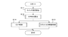
- FIG. 2 is a flowchart for explaining the overall configuration of throttle valve opening control and CVT control by the ECU 5.
- step S11 the setting of the operation mode switch 15 is read, and in step S12, the APREQ calculation process shown in FIG. 3 is executed to calculate the required driving force parameter APREQ.
- step S13 throttle valve opening control is performed based on the required driving force parameter APREQ calculated in step S12, while in step S14, CVT control is performed based on the required driving force parameter APREQ.
- the target engine speed NEOBJ is set according to the required driving force parameter APREQ, and the shift control is performed so that the engine speed NE matches the target engine speed NEOBJ.
- the target engine speed NEOBJ is set so that the minimum fuel consumption rate operation is realized in a predetermined operation state according to the operation mode selected by the operation mode switch 15 and the required driving force parameter APREQ.
- the response speed (transmission response speed) VFB when controlling the engine speed NE to match the target engine speed NEOBJ is set according to the selected operation mode. That is, the eco-driving response speed VFBE is selected in the eco-driving mode, the normal driving response speed VFBN is selected in the normal driving mode, and the sports driving response speed VFBS is selected in the sports driving mode.
- the eco-driving response speed VFBE, the normal driving response speed VFBN, and the sports driving response speed VFBS are set so as to satisfy the relationship of VFBE ⁇ VFBN ⁇ VFBS.
- the response speed VFB is changed by changing a gain coefficient of feedback control for making the engine speed NE coincide with the target engine speed NEOBJ, but for calculating the target engine speed NEOBJ according to the required driving force parameter APREQ.
- the response speed VFB may be substantially changed by changing the map setting for each operation mode.
- FIG. 3 shows a flowchart of processing for calculating the required driving force parameter APREQ. This process is executed by the CPU of the ECU 5 every predetermined time.
- step S21 an APREQE map shown in FIG. 4A is retrieved according to the accelerator pedal operation amount AP and the vehicle speed VP, and an eco-drive request driving force parameter APREQE corresponding to the eco-drive mode is calculated.
- the APREQE map is basically set so that the eco-drive required driving force parameter APREQE increases as the accelerator pedal operation amount AP increases, and the vehicle speed is within a range where the accelerator pedal operation amount AP is smaller than about 70%.
- the eco-drive required driving force parameter APREQE is set to increase as VP increases.
- step S22 an APREQN map shown in FIG. 4B is searched according to the accelerator pedal operation amount AP and the vehicle speed VP, and a normal driving request driving force parameter APREQN corresponding to the normal driving mode is calculated.
- An alternate long and short dash line L10, a thin broken line L11, a thin solid line L12, a thick broken line L13, and a thick solid line L14 shown in FIG. 4B correspond to the predetermined vehicle speeds VP0, VP1, VP2, VP3, and VP4, respectively. That is, the APREQN map is basically set so that the normal driving request driving force parameter APREQN increases as the accelerator pedal operation amount AP increases, and the vehicle speed is within a range where the accelerator pedal operation amount AP is smaller than about 70%.
- the normal operation required driving force parameter APREQN is set so as to increase as VP increases.
- the slopes of the lines L10 to L14 are set to be larger than the slopes of the lines L0 to L4 in a range where the accelerator pedal operation amount AP is smaller than about 40%. Yes.
- step S23 an APREQS map shown in FIG. 4C is retrieved according to the accelerator pedal operation amount AP and the vehicle speed VP, and a sports driving request driving force parameter APREQS corresponding to the sports driving mode is calculated.
- the dashed-dotted line L20, the thin broken line L21, the thin solid line L22, the thick broken line L23, and the thick solid line L24 shown in FIG. 4C correspond to the predetermined vehicle speeds VP0, VP1, VP2, VP3, and VP4, respectively. That is, the APREQS map is basically set so that the sport driving request driving force parameter APREQS increases as the accelerator pedal operation amount AP increases, and the accelerator pedal operation amount AP is smaller than about 70%.
- the sport driving request driving force parameter APREQS is set to increase as the vehicle speed VP increases.
- the slopes of the lines L20 to L24 are set to be larger than the slopes of the lines L10 to L14, respectively, when the accelerator pedal operation amount AP is in the range of about 10% to 40%. Has been.
- step S24 it is determined whether or not the eco operation mode flag FMEC is “1”.
- the eco operation mode flag FMEC is set to “1” when the operation mode switch 15 is set to the eco operation mode. If the answer to step S24 is affirmative (YES), it is determined whether or not a first transient control end flag FTREE is “1”. Immediately after shifting from the other driving mode (normal driving mode or sport driving mode) to the eco driving mode, the first transient control end flag FTREE is “0”, so the process proceeds to step S26, and the required driving force parameter APREQ is set to other.
- the transient control for gradually shifting from the required driving force parameter (APREQN or APREQS) to the eco-driving required driving force parameter APREQE is executed.
- step S27 the required driving force parameter APREQ is set to the eco-driving required driving force parameter APREQE.
- step S28 determines whether or not the sports driving mode flag FMSP is “1”.
- the sports driving mode flag FMSP is set to “1” when the driving mode switch 15 is set to the sports driving mode. If the answer to step S28 is affirmative (YES), it is determined whether or not a second transient control end flag FTRSE is “1”. Immediately after the transition from the other driving mode (the normal driving mode or the eco driving mode) to the sports driving mode, the second transient control end flag FTRSE is “0”.
- the transient control for gradually shifting from the required driving force parameter (APREQN or APREQE) to the sports driving required driving force parameter APREQS is executed.
- step S31 the required driving force parameter APREQ is set to the sports driving required driving force parameter APREQS.
- step S28 the operation mode switch 15 is set to the normal operation mode, so the process proceeds to step S32, and it is determined whether or not the third transient control end flag FTRNE is “1”. Immediately after shifting from another driving mode (sport driving mode or eco driving mode) to the normal driving mode, the third transient control end flag FTRNE is “0”. The transient control for gradually shifting from the required driving force parameter (APREQE or APREQS) to the normal driving required driving force parameter APREQN is executed.
- APREQS required driving force parameter
- step S34 the required driving force parameter APREQ is set to the normal driving required driving force parameter APREQN.
- FIG. 5 is a flowchart of the opening degree control process of the throttle valve 3, and this process is executed by the CPU of the ECU 5 every predetermined time.
- step S41 it is determined whether or not the eco-operation mode flag FMEC is “1”. If the answer to step S41 is affirmative (YES), the engine driving speed parameter APREQ and the engine speed NE are set according to FIG.
- the THBE map shown in a) is searched, and the eco-driving basic target opening THBE is calculated (step S42).
- the eco-drive basic target opening THBE is a basic value of the target opening THCMD applied in the eco-drive mode.
- NE4 for example, 2000 rpm
- NE5 for example, 3000 rpm
- a thick solid line L36 corresponds to a rotational speed of a predetermined rotational speed NE6 (for example, 3500 rpm) or more.
- the THBE map is basically set so that the basic target opening degree THBE for eco-drive increases as the required driving force parameter APREQ increases, and the required driving force parameter APREQ is in the range of about 10% to 70%.
- the eco-driving basic target opening degree THBE is set to increase as the engine speed NE increases. Further, when the engine speed NE is the predetermined speed NE1 and the required driving force parameter APREQ is within the predetermined range RCST1, the eco-driving basic target opening THBE is set so as not to change even if the required driving force parameter APREQ changes. Has been.
- the predetermined range RCST1 is referred to as “constant target opening range RCST1”.
- FIG. 6 (a) shows a constant target opening range RCST1 in which the engine speed NE corresponds to the predetermined speed NE1, but as is apparent from the figure, it is also set at other predetermined speeds NE2 to NE5. ing. However, the constant target opening range RCST1 is set to become narrower as the engine speed NE becomes higher.
- the shift response speed of the CVT 20 is slower than the response speed of the throttle valve opening control, by providing a constant target opening range RCST1 to restrict the change in the throttle valve opening TH, the shift control and the throttle valve opening are controlled.
- the minimum fuel consumption rate operation can be reliably realized by coordinating the control.
- step S43 the basic target throttle valve opening THB is set to the eco-driving basic target opening THBE, and the process proceeds to step S49.
- step S41 the process proceeds to step S44 to determine whether or not the sports driving mode flag FMSP is “1”. If the answer is affirmative (YES), the THBS table shown in FIG. 6C is searched according to the required driving force parameter APREQ, and the sport driving basic target opening degree THBS is calculated (step S45).
- the sports driving basic target opening THBS is a basic value of the target opening THCMD applied in the sports driving mode.
- the THBS table is applied to all engine speeds NE, and the sport driving basic target opening degree THBS is uniquely set corresponding to the required driving force parameter APREQ without depending on the engine speed NE. ing. That is, the sport driving basic target opening THBS is set to be proportional to the required driving force parameter APREQ, as indicated by the solid line L51.
- step S46 the basic target throttle valve opening THB is set to the sports driving basic target opening THBS, and the process proceeds to step S49.
- the operation mode switch 15 is set to the normal operation mode, so the THBN map shown in FIG. 6B is searched according to the required driving force parameter APREQ and the engine speed NE. Then, the normal operation basic target opening THBN is calculated (step S47).
- the normal operation basic target opening THBN is a basic value of the target opening THCMD applied in the normal operation mode.
- a dashed line L41, a thin broken line L42, and a thin solid line L43 shown in FIG. 6B correspond to predetermined engine speeds NE1, NE2, and NE3, respectively, and a thick solid line L44 is equal to or higher than a predetermined rotational speed NE3a (for example, 1750 rpm).
- a predetermined rotational speed NE3a for example, 1750 rpm.
- the THBN map is basically set so that the normal operation basic target opening THBN increases as the required driving force parameter APREQ increases, and the required driving force parameter APREQ is in the range of about 10% to 30%.
- the constant target opening range RCST2 is provided in a range where the engine speed NE is equal to or less than the predetermined speed NE3.
- the constant target opening range RCST2 shown in FIG. 6 (b) is set narrower than the constant target opening range RCST1 of the THBE map shown in FIG. 6 (a).
- step S48 the basic target throttle valve opening THB is set to the normal operation basic target opening THBN, and the process proceeds to step S49.
- step S49 when the basic target throttle valve opening THB changes suddenly as the operation mode is switched or the accelerator pedal operation amount AP suddenly increases, transient control is performed to restrict the change speed.
- step S50 correction for adding a correction term for idle operation is performed to calculate the target opening degree THCMD.
- step S51 limit processing for restricting the target opening degree THCMD within a predetermined upper and lower limit value range is performed.
- the change mode of the target opening degree THCMD is the same as the change mode of the basic target throttle valve opening degree THB, except immediately after switching of the operation mode and the idle operation state.
- step S52 drive control of the actuator 11 is performed so that the detected throttle valve opening TH matches the target opening THCMD.
- the required driving force parameter APREQ is set based on the accelerator pedal operation amount AP, and the basic target throttle valve opening THB is set based on the required driving force parameter APREQ.
- a target opening THCMD is calculated from the valve opening THB. Then, the throttle valve 3 is driven so that the actual throttle valve opening TH becomes the target opening THCMD.
- the target engine speed NEOBJ is set based on the required driving force parameter APREQ, and the CVT 20 is controlled so that the engine speed NE matches the target engine speed NEOBJ.
- the required driving force parameter APREQ corresponding to the accelerator pedal operation amount AP is set smaller than the normal driving mode or the sports driving mode, and the engine speed NE and The basic target throttle valve opening THB is calculated using the THBE map set as shown in FIG. 6A in accordance with the required driving force parameter APREQ.
- the THBE map is set so that the basic target opening THBE corresponding to the same engine speed NE is constant when the required driving force parameter APREQ is in the constant target opening range RCST1, so Even if there is a change in the accelerator pedal operation amount AP, the basic target opening degree THBE is held constant if the required driving force parameter APREQ is within the constant target opening range RCST1. Therefore, even when the accelerator pedal is operated by a butterfly, the fuel consumption rate can be prevented from deteriorating.
- the basic operation basics are obtained using the THBN map shown in FIG. 6B set according to the engine speed NE and the required driving force parameter APREQ.
- a target opening THBN is calculated. Similar to the THBE map, the THBN map is set so that the basic target opening THBN corresponding to the same engine speed NE is constant within the constant target opening range RCST2, and the constant target opening of the THBN map is set.
- the degree range RCST2 is set narrower than the constant target opening range RCST1 of the THBE map. Therefore, in the normal operation mode, the range in which the basic target opening degree THBE changes in response to the change in the accelerator pedal operation amount AP is widened, and acceleration response can be improved compared to the eco operation mode.
- the sport driving basic target opening degree THBS is set using the THBS table shown in FIG. 6C set according to the required driving force parameter APREQ. Calculated.
- the THBS table is set to be proportional to the required driving force parameter APREQ so that the basic target opening degree THBS can be uniquely determined without depending on the engine speed NE corresponding to the required driving force parameter APREQ. Therefore, in the sport driving mode, the basic target throttle valve opening THB is set in proportion to the accelerator pedal operation amount AP, and acceleration response can be improved compared to the eco driving mode and the normal driving mode.
- the throttle valve 3 corresponds to a driving force control means
- the ECU 5 is a driving force parameter setting means, a part of the driving means, a target value setting means, a target rotation speed setting means, a shift control means, a first characteristic switching.
- the second characteristic switching means, and the actuator 11 constitutes a part of the driving means.
- the process of FIG. 3 constitutes driving force parameter setting means and first characteristic switching means
- the present invention is not limited to the above-described embodiment, and various modifications are possible.
- a valve operating mechanism that can continuously change the lift amount and the valve opening period of the intake valve.
- the present invention is also applicable to a vehicle driven by an internal combustion engine equipped with (for example, disclosed in Japanese Patent Application Laid-Open No. 2008-25418).
- the valve mechanism including the intake valve corresponds to the driving force control means
- the control parameter for changing the lift amount and the valve opening period of the intake valve corresponds to the control amount of the driving force control means.
- the present invention can also be applied to a vehicle driven by a diesel engine.
- the driving force is controlled by changing the fuel injection amount. Therefore, the fuel injection valve corresponds to the driving force control means, and the valve opening time of the fuel injection valve corresponds to the control amount.
- the present invention can be applied to control of a hybrid vehicle including an internal combustion engine and a motor (electric motor) as a prime mover for driving the vehicle.
- a hybrid vehicle including an internal combustion engine and a motor (electric motor) as a prime mover for driving the vehicle.
- the fuel consumption rate can be further reduced by increasing the ratio of the motor driving force to the vehicle required driving force.
- the vehicle control device in which the three driving modes of the eco driving mode, the normal driving mode, and the sports driving mode can be selected has been shown.
- the present invention has two modes of the eco driving mode and the normal driving mode.
- the present invention can also be applied to a vehicle control device in which an operation mode can be selected.
- the present invention can be applied to a vehicle control device having a function of coaching an accelerator pedal operation to a driver (instructing a desired accelerator pedal operation amount AP), for example, even for a driver unfamiliar with driving. It is possible to easily perform the operation along the coaching for performing the fuel consumption rate operation.
- Throttle valve drive force control means
- throttle valve opening sensor 5 electronic control unit (driving force parameter setting means, driving means, target value setting means, target rotational speed setting means, shift control means, first characteristic switching means, second characteristic switching means)
- Actuator drive means
- accelerator sensor 14 vehicle speed sensor 15 operation mode switch 20 continuously variable transmission
Landscapes
- Engineering & Computer Science (AREA)
- Chemical & Material Sciences (AREA)
- Combustion & Propulsion (AREA)
- Mechanical Engineering (AREA)
- Transportation (AREA)
- Automation & Control Theory (AREA)
- Human Computer Interaction (AREA)
- General Engineering & Computer Science (AREA)
- Control Of Vehicle Engines Or Engines For Specific Uses (AREA)
- Control Of Transmission Device (AREA)
- Control Of Driving Devices And Active Controlling Of Vehicle (AREA)
- Electrical Control Of Air Or Fuel Supplied To Internal-Combustion Engine (AREA)
Priority Applications (3)
| Application Number | Priority Date | Filing Date | Title |
|---|---|---|---|
| CN2009801360533A CN102159438B (zh) | 2008-09-17 | 2009-09-10 | 车辆的控制装置 |
| EP09814511.3A EP2325062B1 (de) | 2008-09-17 | 2009-09-10 | Steuergerät für ein fahrzeug |
| US13/119,093 US8892316B2 (en) | 2008-09-17 | 2009-09-10 | Control system for vehicle |
Applications Claiming Priority (2)
| Application Number | Priority Date | Filing Date | Title |
|---|---|---|---|
| JP2008237271A JP4818337B2 (ja) | 2008-09-17 | 2008-09-17 | 車両の制御装置 |
| JP2008-237271 | 2008-09-17 |
Publications (1)
| Publication Number | Publication Date |
|---|---|
| WO2010032666A1 true WO2010032666A1 (ja) | 2010-03-25 |
Family
ID=42039490
Family Applications (1)
| Application Number | Title | Priority Date | Filing Date |
|---|---|---|---|
| PCT/JP2009/065786 WO2010032666A1 (ja) | 2008-09-17 | 2009-09-10 | 車両の制御装置 |
Country Status (5)
| Country | Link |
|---|---|
| US (1) | US8892316B2 (de) |
| EP (1) | EP2325062B1 (de) |
| JP (1) | JP4818337B2 (de) |
| CN (1) | CN102159438B (de) |
| WO (1) | WO2010032666A1 (de) |
Cited By (3)
| Publication number | Priority date | Publication date | Assignee | Title |
|---|---|---|---|---|
| CN102416957A (zh) * | 2010-09-28 | 2012-04-18 | 宝马股份公司 | 用于支持驾驶员用以控制消耗地行驶的辅助系统 |
| CN102844593A (zh) * | 2011-04-20 | 2012-12-26 | 丰田自动车株式会社 | 带式无级变速器的控制装置 |
| US20130131940A1 (en) * | 2010-08-04 | 2013-05-23 | Yamaha Hatsudoki Kabushiki Kaisha | Vehicle and drive control device for vehicle |
Families Citing this family (16)
| Publication number | Priority date | Publication date | Assignee | Title |
|---|---|---|---|---|
| KR101157525B1 (ko) * | 2010-09-16 | 2012-06-22 | 주식회사 이엠티 | 차량의 연비 절감을 위한 스로틀 제어방법 |
| JP5742949B2 (ja) * | 2011-09-20 | 2015-07-01 | トヨタ自動車株式会社 | 車両の駆動力制御装置 |
| WO2013046308A1 (ja) | 2011-09-27 | 2013-04-04 | トヨタ自動車株式会社 | 車両の駆動力制御装置 |
| US8682550B2 (en) | 2011-10-14 | 2014-03-25 | Polaris Industries Inc. | Primary clutch electronic CVT |
| US8534413B2 (en) * | 2011-10-14 | 2013-09-17 | Polaris Industries Inc. | Primary clutch electronic CVT |
| JP2013203287A (ja) * | 2012-03-29 | 2013-10-07 | Denso Corp | ハイブリッド車の制御装置 |
| JP6052285B2 (ja) * | 2012-04-02 | 2016-12-27 | 日産自動車株式会社 | 変速比制御装置及び変速比制御方法 |
| EP2974930B1 (de) * | 2013-03-12 | 2019-12-11 | Yamaha Hatsudoki Kabushiki Kaisha | Fahrzeugsteuerungsvorrichtung und motorrad |
| JP5920306B2 (ja) * | 2013-10-02 | 2016-05-18 | トヨタ自動車株式会社 | ハイブリッド車両およびハイブリッド車両の制御方法 |
| JP6149814B2 (ja) | 2014-07-04 | 2017-06-21 | トヨタ自動車株式会社 | ハイブリッド車両 |
| US10648554B2 (en) | 2014-09-02 | 2020-05-12 | Polaris Industries Inc. | Continuously variable transmission |
| US20190092312A1 (en) * | 2017-09-26 | 2019-03-28 | Team Industries, Inc. | Multi-mode cvt controller |
| CA3183788A1 (en) | 2018-03-19 | 2019-09-26 | Polaris Industries Inc. | Continuously variable transmission |
| EP3994375A1 (de) * | 2019-07-01 | 2022-05-11 | TEAM Industries, Inc. | Stufenlos schaltbares getriebe mit einheitlicher klemmenbetätigung |
| CN112406852B (zh) * | 2019-08-20 | 2022-04-15 | 纬湃科技投资(中国)有限公司 | 用于混合动力车辆的控制方法及混合动力车辆 |
| EP4015277A1 (de) * | 2020-12-15 | 2022-06-22 | Kubota Corporation | Arbeitsfahrzeug, steuerungsverfahren- und programm sowie aufzeichnungsmedium |
Citations (10)
| Publication number | Priority date | Publication date | Assignee | Title |
|---|---|---|---|---|
| JPS5839870A (ja) | 1981-09-03 | 1983-03-08 | Nissan Motor Co Ltd | エンジン・無段変速機駆動系統の制御装置 |
| JPS5974341A (ja) | 1982-10-19 | 1984-04-26 | Nissan Motor Co Ltd | 車両用アクセル制御装置 |
| JPS6067243U (ja) * | 1983-10-18 | 1985-05-13 | 日産ディーゼル工業株式会社 | 自動車の省燃費運転制御装置 |
| JPS63248939A (ja) * | 1987-04-06 | 1988-10-17 | Mazda Motor Corp | エンジンのスロツトル弁制御装置 |
| JPH0565037A (ja) * | 1991-09-09 | 1993-03-19 | Mazda Motor Corp | 車両のパワートレイン制御装置 |
| JPH06294464A (ja) * | 1992-07-21 | 1994-10-21 | Robert Bosch Gmbh | 連続調整可能トランスミッション(cvt)付き車両でのトランスミッション被駆動トルクまたはトランスミッション出力の調整装置 |
| JPH06338742A (ja) | 1993-05-31 | 1994-12-06 | Clarion Co Ltd | イコライザ装置 |
| JPH11227500A (ja) * | 1998-02-13 | 1999-08-24 | Mazda Motor Corp | パワートレインの制御装置 |
| JP2005061428A (ja) * | 2003-08-11 | 2005-03-10 | Nissan Motor Co Ltd | 無段変速機の制御装置 |
| JP2008025418A (ja) | 2006-07-19 | 2008-02-07 | Honda Motor Co Ltd | 内燃機関の可変動弁機構 |
Family Cites Families (31)
| Publication number | Priority date | Publication date | Assignee | Title |
|---|---|---|---|---|
| EP0073475B1 (de) * | 1981-08-27 | 1988-02-03 | Nissan Motor Co., Ltd. | Vorrichtung und Verfahren zum Steuern eines Motors und eines stufenlos regelbares Wechselgetriebes |
| JPS6141631A (ja) * | 1984-08-03 | 1986-02-28 | Nissan Motor Co Ltd | エンジン・無段変速機の制御装置 |
| US4793217A (en) * | 1985-09-17 | 1988-12-27 | Toyota Jidosha Kabushiki Kaisha | Method and apparatus for controlling power transmitting system for automotive vehicle, including continuously variable transmission and auxiliary transmission |
| JP2805061B2 (ja) | 1986-08-01 | 1998-09-30 | トヨタ自動車株式会社 | 車両駆動系の制御装置 |
| JPH03121357A (ja) * | 1989-10-04 | 1991-05-23 | Nissan Motor Co Ltd | 無段変速機の変速制御装置 |
| JP2568923B2 (ja) * | 1989-10-16 | 1997-01-08 | 本田技研工業株式会社 | 無段変速機の制御方法 |
| JP3369594B2 (ja) * | 1992-05-29 | 2003-01-20 | 本田技研工業株式会社 | 電気走行車 |
| DE19625936A1 (de) * | 1996-06-28 | 1998-01-08 | Bosch Gmbh Robert | System zur Einstellung einer Getriebeübersetzung |
| US5961418A (en) * | 1996-10-25 | 1999-10-05 | Aisin Aw Co., Ltd. | Infinitely variable transmission |
| JP3409669B2 (ja) * | 1997-03-07 | 2003-05-26 | 日産自動車株式会社 | 無段変速機の変速制御装置 |
| US6066070A (en) * | 1998-04-28 | 2000-05-23 | Toyota Jidosha Kabushiki Kaisha | Control system of vehicle having continuously variable transmission |
| JP3536704B2 (ja) * | 1999-02-17 | 2004-06-14 | 日産自動車株式会社 | 車両の駆動力制御装置 |
| JP3559200B2 (ja) * | 1999-07-13 | 2004-08-25 | 本田技研工業株式会社 | 車両用動力伝達装置の制御装置 |
| JP3546302B2 (ja) * | 1999-08-05 | 2004-07-28 | トヨタ自動車株式会社 | 無段変速機を備えた車両の制御装置 |
| JP3785901B2 (ja) * | 2000-05-19 | 2006-06-14 | トヨタ自動車株式会社 | 無段変速機の変速制御装置 |
| JP3633484B2 (ja) * | 2001-01-22 | 2005-03-30 | トヨタ自動車株式会社 | 内燃機関と無段変速機とを有する車両の制御装置 |
| JP4489333B2 (ja) * | 2001-09-26 | 2010-06-23 | 日産自動車株式会社 | 車両の駆動力制御装置 |
| JP2003172443A (ja) * | 2001-12-10 | 2003-06-20 | Honda Motor Co Ltd | 車両用動力伝達制御装置 |
| JP3648739B2 (ja) * | 2002-03-18 | 2005-05-18 | トヨタ自動車株式会社 | 動力出力装置およびこれを搭載する自動車 |
| JP3977701B2 (ja) * | 2002-07-17 | 2007-09-19 | 日野自動車株式会社 | アクセル制御装置 |
| DE102004028101B4 (de) * | 2003-06-12 | 2008-12-18 | Honda Motor Co., Ltd. | Kraftübertragungsvorrichtung für ein Hybridfahrzeug |
| JP2006298317A (ja) * | 2005-04-25 | 2006-11-02 | Toyota Motor Corp | 駆動力制御装置 |
| JP4946236B2 (ja) * | 2005-08-05 | 2012-06-06 | 日産自動車株式会社 | ロックアップ制御装置 |
| US7490000B2 (en) * | 2006-08-29 | 2009-02-10 | Ford Motor Company | Fuel economy control system and control strategy |
| JP5209258B2 (ja) * | 2006-10-27 | 2013-06-12 | ヤマハ発動機株式会社 | 鞍乗型車両 |
| JP5134238B2 (ja) * | 2006-12-15 | 2013-01-30 | 株式会社小松製作所 | 作業車両のエンジン負荷制御装置 |
| JP2008168866A (ja) * | 2007-01-15 | 2008-07-24 | Toyota Motor Corp | 車両駆動装置の制御方法および制御装置 |
| JP2008207690A (ja) * | 2007-02-27 | 2008-09-11 | Toyota Motor Corp | 車両用駆動装置の制御装置 |
| JP4197037B2 (ja) * | 2007-03-14 | 2008-12-17 | トヨタ自動車株式会社 | ハイブリッド自動車およびその制御方法 |
| JP5098402B2 (ja) * | 2007-04-06 | 2012-12-12 | トヨタ自動車株式会社 | 車両用駆動装置の制御装置 |
| US7801661B2 (en) * | 2007-06-08 | 2010-09-21 | Ford Global Technologies | Power boost system and method |
-
2008
- 2008-09-17 JP JP2008237271A patent/JP4818337B2/ja not_active Expired - Fee Related
-
2009
- 2009-09-10 WO PCT/JP2009/065786 patent/WO2010032666A1/ja active Application Filing
- 2009-09-10 CN CN2009801360533A patent/CN102159438B/zh active Active
- 2009-09-10 US US13/119,093 patent/US8892316B2/en active Active
- 2009-09-10 EP EP09814511.3A patent/EP2325062B1/de not_active Not-in-force
Patent Citations (10)
| Publication number | Priority date | Publication date | Assignee | Title |
|---|---|---|---|---|
| JPS5839870A (ja) | 1981-09-03 | 1983-03-08 | Nissan Motor Co Ltd | エンジン・無段変速機駆動系統の制御装置 |
| JPS5974341A (ja) | 1982-10-19 | 1984-04-26 | Nissan Motor Co Ltd | 車両用アクセル制御装置 |
| JPS6067243U (ja) * | 1983-10-18 | 1985-05-13 | 日産ディーゼル工業株式会社 | 自動車の省燃費運転制御装置 |
| JPS63248939A (ja) * | 1987-04-06 | 1988-10-17 | Mazda Motor Corp | エンジンのスロツトル弁制御装置 |
| JPH0565037A (ja) * | 1991-09-09 | 1993-03-19 | Mazda Motor Corp | 車両のパワートレイン制御装置 |
| JPH06294464A (ja) * | 1992-07-21 | 1994-10-21 | Robert Bosch Gmbh | 連続調整可能トランスミッション(cvt)付き車両でのトランスミッション被駆動トルクまたはトランスミッション出力の調整装置 |
| JPH06338742A (ja) | 1993-05-31 | 1994-12-06 | Clarion Co Ltd | イコライザ装置 |
| JPH11227500A (ja) * | 1998-02-13 | 1999-08-24 | Mazda Motor Corp | パワートレインの制御装置 |
| JP2005061428A (ja) * | 2003-08-11 | 2005-03-10 | Nissan Motor Co Ltd | 無段変速機の制御装置 |
| JP2008025418A (ja) | 2006-07-19 | 2008-02-07 | Honda Motor Co Ltd | 内燃機関の可変動弁機構 |
Non-Patent Citations (1)
| Title |
|---|
| See also references of EP2325062A4 |
Cited By (5)
| Publication number | Priority date | Publication date | Assignee | Title |
|---|---|---|---|---|
| US20130131940A1 (en) * | 2010-08-04 | 2013-05-23 | Yamaha Hatsudoki Kabushiki Kaisha | Vehicle and drive control device for vehicle |
| EP2602463A4 (de) * | 2010-08-04 | 2018-04-11 | Yamaha Hatsudoki Kabushiki Kaisha | Fahrzeug und antriebssteuervorrichtung für ein fahrzeug |
| CN102416957A (zh) * | 2010-09-28 | 2012-04-18 | 宝马股份公司 | 用于支持驾驶员用以控制消耗地行驶的辅助系统 |
| CN102416957B (zh) * | 2010-09-28 | 2016-08-03 | 宝马股份公司 | 用于支持驾驶员用以控制消耗地行驶的辅助系统 |
| CN102844593A (zh) * | 2011-04-20 | 2012-12-26 | 丰田自动车株式会社 | 带式无级变速器的控制装置 |
Also Published As
| Publication number | Publication date |
|---|---|
| CN102159438B (zh) | 2013-12-11 |
| EP2325062B1 (de) | 2013-07-10 |
| JP4818337B2 (ja) | 2011-11-16 |
| EP2325062A4 (de) | 2012-04-04 |
| CN102159438A (zh) | 2011-08-17 |
| JP2010069966A (ja) | 2010-04-02 |
| US8892316B2 (en) | 2014-11-18 |
| US20110166755A1 (en) | 2011-07-07 |
| EP2325062A1 (de) | 2011-05-25 |
Similar Documents
| Publication | Publication Date | Title |
|---|---|---|
| JP4818337B2 (ja) | 車両の制御装置 | |
| JP3815111B2 (ja) | 車両の駆動力制御装置 | |
| JP4503631B2 (ja) | 内燃機関の制御装置 | |
| JP5120323B2 (ja) | パワートレーンのエンジン回転速度制御装置 | |
| JP2011202565A (ja) | 無段変速機の変速制御装置 | |
| KR20090061652A (ko) | 토크 컨버터를 구비한 하이브리드 구동기의 작동 방법 | |
| JP4994794B2 (ja) | 車両のクルーズコントロール装置 | |
| JP3800741B2 (ja) | 無段変速機の足放しアップシフト変速制御装置 | |
| CN111086517B (zh) | 车辆的控制装置 | |
| JP2008239130A (ja) | 車両の制御装置 | |
| JP3577966B2 (ja) | 車両の駆動力制御装置 | |
| US20120310497A1 (en) | Gear-shift control apparatus for automatic transmission | |
| JP5967207B2 (ja) | 車両制御装置および車両の制御方法 | |
| US8965647B2 (en) | Control apparatus for continuously variable transmission | |
| JP6669058B2 (ja) | 車両用駆動装置 | |
| JP2001354051A (ja) | 車両の駆動力制御装置 | |
| JP4854780B2 (ja) | 内燃機関の制御装置 | |
| GB2348298A (en) | Methods for selection of operating mode and control system for an internal combustion engine | |
| JP2007071160A (ja) | 車両の制御装置 | |
| JP4016822B2 (ja) | 無段変速機の変速制御装置 | |
| JP3832241B2 (ja) | 車両の駆動力制御装置 | |
| KR20180053075A (ko) | 작업차의 엔진 특성 제어 방법 | |
| JP6318950B2 (ja) | 車両の制御装置 | |
| JP4412047B2 (ja) | 内燃機関の吸気制御装置 | |
| JP4122585B2 (ja) | 車両の駆動力制御装置 |
Legal Events
| Date | Code | Title | Description |
|---|---|---|---|
| WWE | Wipo information: entry into national phase |
Ref document number: 200980136053.3 Country of ref document: CN |
|
| 121 | Ep: the epo has been informed by wipo that ep was designated in this application |
Ref document number: 09814511 Country of ref document: EP Kind code of ref document: A1 |
|
| WWE | Wipo information: entry into national phase |
Ref document number: 2009814511 Country of ref document: EP |
|
| WWE | Wipo information: entry into national phase |
Ref document number: 13119093 Country of ref document: US |
|
| NENP | Non-entry into the national phase |
Ref country code: DE |