WO2010029703A1 - Machine à laver et à sécher - Google Patents
Machine à laver et à sécher Download PDFInfo
- Publication number
- WO2010029703A1 WO2010029703A1 PCT/JP2009/004280 JP2009004280W WO2010029703A1 WO 2010029703 A1 WO2010029703 A1 WO 2010029703A1 JP 2009004280 W JP2009004280 W JP 2009004280W WO 2010029703 A1 WO2010029703 A1 WO 2010029703A1
- Authority
- WO
- WIPO (PCT)
- Prior art keywords
- washing
- air
- path
- drying machine
- tub
- Prior art date
Links
Images


Classifications
-
- D—TEXTILES; PAPER
- D06—TREATMENT OF TEXTILES OR THE LIKE; LAUNDERING; FLEXIBLE MATERIALS NOT OTHERWISE PROVIDED FOR
- D06F—LAUNDERING, DRYING, IRONING, PRESSING OR FOLDING TEXTILE ARTICLES
- D06F25/00—Washing machines with receptacles, e.g. perforated, having a rotary movement, e.g. oscillatory movement, the receptacle serving both for washing and for centrifugally separating water from the laundry and having further drying means, e.g. using hot air
-
- D—TEXTILES; PAPER
- D06—TREATMENT OF TEXTILES OR THE LIKE; LAUNDERING; FLEXIBLE MATERIALS NOT OTHERWISE PROVIDED FOR
- D06F—LAUNDERING, DRYING, IRONING, PRESSING OR FOLDING TEXTILE ARTICLES
- D06F58/00—Domestic laundry dryers
- D06F58/20—General details of domestic laundry dryers
- D06F58/203—Laundry conditioning arrangements
-
- D—TEXTILES; PAPER
- D06—TREATMENT OF TEXTILES OR THE LIKE; LAUNDERING; FLEXIBLE MATERIALS NOT OTHERWISE PROVIDED FOR
- D06F—LAUNDERING, DRYING, IRONING, PRESSING OR FOLDING TEXTILE ARTICLES
- D06F58/00—Domestic laundry dryers
- D06F58/02—Domestic laundry dryers having dryer drums rotating about a horizontal axis
Definitions
- the present invention relates to a washing / drying machine.
- washing and drying machines generally have a special course in which an object is put into a washing tub and several tens of minutes are operated.
- Specific sterilization / deodorization means include, for example, heating in the tank, utilization of ozone, use of chemicals, etc., but the basic is to apply heat.
- the inside of the washing machine tank has been a concern as a place where bacteria and molds are likely to occur. This retains much moisture in the washing machine due to residual water. Another reason is that a person keeps the clothes in the washing tub until the washing machine is driven, so that germs attached to the clothes enter the tub. Furthermore, the appearance of the washing and drying machine has increased the airtightness of the washing tub, which further increases the heat retention and moisture retention.
- Patent Document 1 describes that the surface of a washing tub is covered with a resin film containing an organic microbial growth inhibitory substance.
- Patent Document 2 discloses disinfecting and antibacterial clothing by supplying Ag ions at the time of rinsing, as well as disinfecting and preventing mold on the washing tub.
- washing debris or the like may adhere to the surface of the washing tub, and bacteria and molds may propagate from there.
- the antibacterial components of the washing machine components do not come into contact with the fungus, fungus, etc., so that the antibacterial effect cannot be exerted and even if added. It has been confirmed that it is not effective.
- the washing / drying machine of the present invention includes a washing tub that accommodates laundry, an outer tub in which the washing tub is rotatably installed, a housing that elastically supports the outer tub, and a water supply device that supplies washing water to the outer tub.
- a heating device that heats the air in the outer tub, a circulating air passage that circulates the air in the outer tub through the heating device, a blower that pumps and circulates the air in the circulating air passage,
- an electrostatic atomization generator for supplying the electromist generation particles into the washing tub and the outer tub, and the electrostatic atomization generator is arranged in the circulation air flow path.
- Such a washing dryer can supply electrostatic atomization generation particles to the outer tub using a circulation air passage used at the time of drying, and can efficiently prevent washing and sterilization of the washing tub and mold. Can be done.
- the electrostatic atomization-generating particles are fine water molecule masses that are charged with electricity, and contain radicals having a high oxidative decomposition action.
- By supplying the electrostatic atomization-generating particles with the electrostatic atomization generator it is possible to realize sterilization, deodorization, and mold growth suppression without using heat as in the prior art. Unlike conventional means for sterilization, deodorization, and mold control, low running costs can be realized by not using heat.
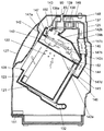
- FIG. 1 is a cross-sectional view showing the main configuration of the washing and drying machine according to Embodiment 1 of the present invention.
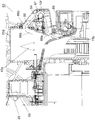
- FIG. 2 is an internal rear view showing the circulation air flow path and the outer tank back of the washing and drying machine.
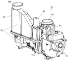
- FIG. 3 is a perspective view showing the inside of the heat pump blower unit of the washing and drying machine.
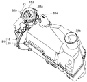
- FIG. 4 is a perspective view of a heat pump blower unit of the washer / dryer.
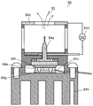
- FIG. 5 is a cross-sectional view showing the inside of the electrostatic atomization generator of the washing / drying machine.
- FIG. 6 is a perspective view showing the vicinity of the fixed plate of the atomizing discharge block of the washer / dryer.
- FIG. 7 is a cross-sectional view showing the inside of the atomizing discharge block of the washing / drying machine.
- FIG. 8 is a longitudinal sectional view of the washing and drying machine according to the second embodiment of the present invention.
- FIG. 9 is a longitudinal sectional view of another part of the washing / drying machine.
- FIG. 10 is another longitudinal sectional view of another part of the washing / drying machine.
- FIG. 1 is a cross-sectional view showing the main configuration of the washing and drying machine according to Embodiment 1 of the present invention
- FIG. 2 is an internal rear view showing the circulation air flow path and the outer tub back of the washing and drying machine
- FIG. It is a perspective view which shows the inside of the heat pump ventilation unit of a dryer.
- the washing tub 2 for storing the laundry is installed in the outer tub 3 so that the rotation axis direction is horizontal or inclined downward from the horizontal direction toward the rear.
- the washing / drying machine 1 includes a drying process in addition to washing, rinsing, and dehydration processes.
- the air in the outer tub 3 is sucked by the blower unit 15 through the circulation blower path 5, dehumidified and heated through the evaporator 31 and the condenser 32, and then repeatedly blown into the outer tub 3 for washing.
- the washing / drying machine 1 is equipped with a heat pump blower unit 81 connected in the middle of the circulation blower path 5.
- the heat pump blower unit 81 is configured by connecting the heat pump device 39 and the blower unit 15.
- the heat pump device 39 includes an evaporator 31 and a condenser 32 that are integrally formed, a compressor 37 that circulates a refrigerant through them, and the like.
- the heat pump device 39 is a heating device that heats the air in the outer tub 3.
- the blower unit 15 is a blower that pumps and circulates the air in the circulation blower path 5. By using the heat pump device 39 as the heating device, heating with high thermal efficiency can be performed.
- an opening portion 11 that is a clothing entrance leading to the opening end of the washing tub 2 is formed corresponding to the horizontal arrangement of the washing tub 2 or the illustrated inclination.
- the door 9 opens and closes the opening 11.
- the opening 11 is formed on the front side of the washing / drying machine main body 44 and is provided on the upward inclined surface.
- the washing and drying machine main body 44 that is a casing elastically supports the outer tub 3 by a suspension.
- the laundry can be taken in and out of the washing tub 2 by opening the door 9.
- the door 9 is provided on the upward inclined surface, the work for putting in and out the laundry can be performed without bending the waist.
- the washing tub 2 has a number of through holes 8 communicating with the outer tub 3 on its peripheral surface, and is provided with stirring protrusions 10 at a plurality of positions in the circumferential direction on the inner peripheral surface.
- the washing tub 2 is rotationally driven in the forward and reverse directions by a motor 7 attached to the rear side of the outer tub 3.
- a water injection pipe 12 and a drain pipe 13 are connected to the outer tub 3 by water, and water is poured into and drained from the outer tub 3 by controlling a water injection valve (not shown) and a drain valve. That is, a water supply apparatus including the water injection pipe 12, the water injection valve, and the like supplies washing water to the outer tub 3.
- the operation of the washing process will be described in order.
- the door 9 is opened, and laundry and detergent are put into the washing tub 2.
- the operation of the washing / drying machine 1 is started, for example, by an operation on the operation panel provided at the upper front of the washing / drying machine 1 through control by a control board or the like provided inside the operation panel.
- a predetermined amount of water is injected into the outer tub 3 from the water injection pipe 12, and the washing tub 2 is rotationally driven by the motor 7 to start the washing process.
- the washing tub 2 By the rotation of the washing tub 2, the laundry stored in the washing tub 2 is lifted in the rotation direction by the stirring protrusion 10 provided on the inner peripheral wall of the washing tub 2, and the stirring operation of dropping from the lifted appropriate height Is repeated. For this reason, the laundry is subjected to tapping and washing.
- the dirty washing liquid is discharged from the drain line 13. And the washing
- water is injected into the outer tub 3 from the water injection pipe 12 to carry out a rinsing process.
- the laundry stored in the washing tub 2 is repeatedly rinsed by the rotation of the washing tub 2 and the stirring operation of being lifted and dropped by the stirring protrusion 10.
- the rinsing process is finished, the water is drained and the laundry is drained by a dehydrating operation of rotating the washing tub 2 at a high speed to finish the washing.
- the door 9 is opened and the laundry is put into the washing tub 2.
- the operation is started through control by a control board or the like provided on the inside of the operation panel by an operation on an operation panel provided on the front upper portion of the washing / drying machine 1, for example.
- the air in the outer tub 3 is sucked through the circulation blower path 5 by the blower unit 15.
- the air in the outer tub 3 is passed through the filter box 5d to the evaporator 31 and the condenser 32, and is dehumidified and heated to be circulated and blown into the outer tub 3. While repeating this circulation, the moisture contained in the clothing is removed and the laundry is dried.
- the rotation mode and the stationary mode of the washing tub 2 can be selected according to the object to be dried.
- FIG. 4 is a perspective view of the heat pump blower unit of the washer / dryer according to Embodiment 1 of the present invention
- FIG. 5 is a sectional view showing the inside of the electrostatic atomization generator of the washer / dryer
- FIG. 6 is the washer / dryer.
- FIG. 7 is a cross-sectional view showing the inside of the atomizing discharge block of the washing / drying machine.
- the operation course of the washing / drying machine 1 includes a washing course in which only a washing process is performed, a drying course in which only drying is performed, a laundry drying course in which washing is continuously performed from drying to drying, and nanoe which performs sterilization and deodorization.
- a washing course in which only a washing process is performed
- a drying course in which only drying is performed
- a laundry drying course in which washing is continuously performed from drying to drying
- nanoe which performs sterilization and deodorization.
- the nano ecourse uses a circulation air passage 5 used in the air circulation in the outer tub 3 in the drying process.
- An electrostatic atomization generator 83 that generates electrostatic atomization generation particles 82 for realizing sterilization and deodorization is provided in the circulation air flow path 5.
- the rotation mode of the washing tub 2 and a stationary mode can be selected according to a target object, and driving
- the Nanoe tank clean mode that automatically exposes the electrostatic atomization generated particles 82 to the washing tub 2 and the outer tub 3 every time after taking out the clothes is installed, and the mode setting is turned on / off It is possible.
- the operation in the nanoe tank clean mode is performed while the washing tub 2 is stationary for about 60 minutes after the laundry course is completed and the door 9 is opened and closed.
- each of these hygiene-conscious courses is set to a course equivalent to washing and drying, and a dedicated operation button is also provided.
- the electrostatic atomization generating particles 82 have a strong oxidative decomposition ability that acts on the object. Therefore, simply by supplying the electrostatic atomization particles 82 without using heat as in the past, sterilization, deodorization, and mold growth control can be easily achieved without worrying about risks such as material deterioration. it can.
- the washing / drying machine 1 is provided with a special course for exposing the electrostatic atomization generating particles 82 to the stored items stored in the washing tub 2 or the surfaces of the washing tub 2 and the outer tub 3.
- the air blowing unit 15 is composed of a centrifugal fan in which a centrifugal type fan 15a is accommodated in a spiral casing 15b.
- the heat pump device 39 and the blower unit 15 are fitted in the suction connection port 15a of the spiral casing 15b with the suction / discharge port 38a, and are connected to each other in a sealing manner.
- the suction / discharge port 38 a is formed in the end wall on one end side in the left and right longitudinal directions of FIG. 3 of the heat pump case 38.
- the suction force of the blower unit 15 acts in the heat pump case 38.
- the suction force of the blower unit 15 acts in the outer tub 3 from the suction introduction port 38b through the suction passage 5a of the circulation blower passage 5 and the filter box 5d. Therefore, the air in the outer tub 3 is sucked into the heat pump case 38 and dehumidified and heated through the evaporator 31 and the condenser 32.
- the dried high-temperature air after dehumidification and heating is sucked into the spiral casing 15b through the suction discharge port 38a and the intake connection port 15c, and from the blowout portion 15d of the spiral casing 15b to the blower bellows connection portion 5b of the circulation blower path 5; The air is blown into the outer tub 3 through the air passage 5c. This is repeated to dry the laundry in the washing tub 2.
- the electrostatic atomization generator 83 is installed in the vicinity of the blowing part 15d.
- the suction inlet 38 b is disposed on the other end side of the heat pump case 38.
- the electrostatic atomization generator 83 is configured to connect the lead wires to the atomization discharge block 84, the transformer printed board 85, the control printed board 86, the element housing 87, the fixed plate 88, and the transformer printed board case 89.
- the transformer printed circuit board 85 generates a high voltage.
- the control printed circuit board 86 controls the atomizing discharge.
- the element housing 87 encloses the atomizing discharge block 84 and forms a bypass path 15f.
- the fixing plate 88 fixes the atomizing discharge block 84 and configures the inlet / outlet shape of the bypass path 15f.
- a transformer printed circuit board 85 is enclosed in the transformer printed circuit board case 89.
- electrostatic atomization generator 83 By installing the electrostatic atomization generator 83 in the circulation air flow path 5, electrostatic atomization is performed in the washing tub 2 and the outer tub 3 with little structural change by utilizing the operation during the drying operation. Generating particles 82 can be supplied. Moreover, the electrostatic atomization generation
- the aluminum heat exchange fin is attenuated by about 70%, and the aluminum fan 15a is attenuated by about 25%. Therefore, it is desirable to install the electrostatic atomization generator 83 in the vicinity of the outer tub 3 without using the aluminum heat exchange fins or the aluminum fan 15a.
- the electrostatic atomization generator 83 of the washing / drying machine 1 according to the first embodiment of the present invention is installed in the vicinity of the blowing unit 15 d of the blower unit 15. Therefore, the transmission loss of the electrostatic atomization generation
- the electrostatic atomization generator 83 is disposed on the side of the washer / dryer main body 44 cut from the movable part on the outer tub 3 side by the blower bellows connection part 5b. Thereby, durability reliability can be improved by not attaching the electrostatic atomization generator 83 which is a precise key device to the outer tank 3 side which vibrates at the time of dehydration.
- the electrostatic atomization generator 83 is configured integrally with a blowing portion 15 d which is a pressure air discharge side of the blower unit 15. Specifically, as shown in FIG. 5, an opening is provided on the wall surface of the spiral casing 15 b and the seal is fixed so as to be covered by the electrostatic atomization generator 83 including the bypass path 15 f. As a result, it is not necessary to newly provide the electrostatic atomization generator 83 in the circulation air flow path 5, and the system becomes simpler and less expensive, and further improves the assemblability and the man-hours. In addition, atomization and air blowing are effective only when integrated as functions, and it is desirable to unitize them.
- the electrostatic atomization generator 83 has a main flow path 15e and a bypass path 15f that merge after branching in two directions inside the unit, and the atomization discharge block 84 is disposed in the bypass path 15f. Yes. Thereby, generation
- the optimum air volume and speed for placing the electrostatic atomization generated particles 82 on the circulating air is the opening area of the fixed plate intake port 88a protruding into the bypass path 15f.
- the optimum wind speed for discharging the electrostatic atomization generating particles 82 is desirably around 1 m / s, and the opening amount of the fixed plate intake port 88a is designed in accordance with this.
- the exhaust side opening 88b portion of the fixed plate 88 winds in parallel with the flow direction of the circulating air in the circulation air flow path 5 to the main flow side path 15e at the junction of the bypass path 15f and the main flow side path 15e.
- a conducting plate 88c is disposed.
- the atomizing discharge block 84 includes a counter electrode 84b, a water supply device 84c, and a voltage application device 84d.
- the voltage application device 84d generates a high voltage between the discharge electrode 84a and the counter electrode 84b. When applied, the water supplied to the discharge electrode 84a is electrostatically atomized.
- the counter electrode 84b is disposed to face the discharge electrode 84a.
- the water supply device 84c supplies water to the discharge electrode 84a.
- Embodiment 1 of the present invention a negative voltage of 4.85 kV is applied between the discharge electrode 84a and the counter electrode 84b to electrostatically atomize water, and feedback is performed so that the discharge current value at that time is about 6 ⁇ A. Control is in progress.
- the discharge electrode 84a side becomes a negative electrode and charges are concentrated, and water attached to the surface of the discharge electrode 84a rises in a conical shape to form a Taylor cone. Then, the charge concentrates at the tip of the Taylor cone to become high density, and the Rayleigh splitting in which water splits and scatters as it is repelled by the repulsive force of the high density charge is repeated. At this time, the formation of the Taylor cone is affected by the wettability of the surface of the discharge electrode 84a. Therefore, if the wettability is low, the predetermined Taylor cone is not formed and electrostatic atomization cannot be performed. It is necessary to secure a predetermined amount.
- the water supply device 84c includes a cooling device including a Peltier element 84e.
- the discharge electrode 84a is cooled by this cooling device, and water is supplied by causing moisture (humidity) in the air to condense on the surface of the distal end portion of the discharge electrode 84a.
- the amount of water required for electrostatic atomization is about 0.5 ml / h.
- the end of the Peltier element 84e on the discharge electrode 84a side is a cooling portion 84f, and the opposite end is a heat dissipation portion 84g.
- the cooling part 84f is connected to the discharge electrode 84a, and the heat radiating part 84g is connected to the heat radiating fin 84h.
- the air flowing in the bypass path 15f of the electrostatic atomization generator 83 is configured to flow in contact with the heat radiating fins 84h, and this air flow is used for heat dissipation when atomizing discharge is performed.
- the necessary heat radiation amount during atomizing discharge is determined, and therefore the minimum required wind speed is determined by determining the heat-dissipating fins.
- 0.5 m / s or more is required, but a sufficient wind speed higher than that is ensured.
- the washer / dryer 1 has a negative pressure with respect to the atmospheric pressure when the air in the outer tub 3 is circulated via the circulation air passage 5.
- a first opening 51 is provided around the filter box 5d.
- the outside air intake section 5h is configured by connecting an opening / closing valve 5g and an outside air introduction duct 5e to the first opening 51.
- a second opening 52 is provided in a part of the circulation air passage 5 in the vicinity of the filter box 5d where the positive pressure or the dynamic pressure of the circulating air acts on the atmospheric pressure.
- the circulating air discharge duct 5f is connected to the 2nd opening part 52, and the circulating air discharge part 5i is comprised.
- the washing / drying machine 1 is designed to be highly airtight for drying, and if the door 9 is closed, there is almost no exchange of air between the outside of the machine and the inside of the tank. Since it is a washing machine, there is not a little water remaining, so the relative humidity in the tank when the door 9 is closed will soon exceed 90%.
- High humidity is not suitable as an environment for discharging, and even when the electrostatic atomization generator 83 is operated, the relative humidity in the tank needs to be 85% or less. Therefore, the abnormal discharge can be prevented from occurring by gradually replacing the air in the outer tub 3 with the outside air.
- the opening / closing valve 5g is opened and the air volume by the blower unit 15 is increased to actively replace the air in the outer tub 3 with the outside air.
- the opening / closing valve 5g is normally opened from the start of the course, and the dehumidifying operation is performed by operating the heat pump device 39 for about 2 minutes after 3 minutes from the start while replacing the air in the outer tub 3 with the outside air. To ensure operational stability.
- the electrostatic atomization generator 83 is operated together with the pressure of the circulating air in the circulating air passage 5 by the air blowing unit 15.
- grains 82 can be efficiently exposed to a target object.
- FIG. 8 is a longitudinal sectional view of the washing / drying machine according to Embodiment 2 of the present invention.
- description of the same configuration, operation, and effect as in the first embodiment will be omitted, and only different points will be described.
- a rotating drum 121 which is a washing tub of a drum type washing and drying machine, is formed in a bottomed cylindrical shape and is provided with a large number of through holes 122 on the entire outer periphery thereof, inside a water receiving tub 123 that is an outer tub. It is rotatably arranged.
- a rotation shaft 124 is provided at a rotational center of the rotating drum 121 so as to be inclined from the horizontal direction, and the axial center direction of the rotating drum 121 is inclined downward from the front side toward the back side.
- a motor 125 attached to the rear surface of the water receiving tank 123 is connected to the rotating shaft 124, and the rotating drum 121 is rotated in the forward and reverse directions.
- Several protruding plates 126 are provided on the inner wall surface of the rotating drum 121.
- the opening provided in the upward inclined surface on the front side of the water receiving tub 123 is covered with a lid 127 so as to be opened and closed, and by opening the lid 127, the laundry can be taken in and out of the rotary drum 121 through the clothing doorway 128. Yes. Since the lid 127 is provided on the upward inclined surface, the laundry can be carried out without bending the waist.
- the water receiving tank 123 is suspended from the washing / drying machine main body 129 by the spring body 130 and the damper 131 so as to be swingable.
- One end of the drainage path 132 is connected to the lower part of the water receiving tank 123, and the other end of the drainage path 132 is connected to the drain valve 133 so that the washing water in the water receiving tank 123 is drained.
- the water supply valve 134 supplies water into the water receiving tank 123 through the water supply path 135.
- the water level detection device 136 detects the water level in the water receiving tank 123.
- the rotation shaft 124 is provided at the rotation center of the rotating drum 121 from the horizontal direction, and the axial center direction of the rotating drum 121 is inclined downward from the front side to the back side.
- a rotating shaft 124 may be provided in the horizontal direction at the rotation center of the rotating drum 121, and the axial center direction of the rotating drum 121 may be disposed in the horizontal direction.
- FIG. 9 is a longitudinal sectional view of another part of the washing and drying machine according to the second embodiment of the present invention.
- the drying function includes a heater (heating device) 137, a blower fan (blower device) 138, and a fan case (part of the circulating air passage) 139 that accommodates the heater 137 and the blower fan 138 therein. Is attached to the washing and drying machine main body 129.
- the body portion of the water receiving tank 123 is provided with a hot air intake port (a part of the circulation air flow path) 140 for taking in air in the water receiving tank 123, and the hot air air blowing port 141 is provided on the back surface of the water receiving tank 123. ing.
- the water receiving tank 123 is integrally provided with a heat exchange path (a part of the circulating air blowing path) 142.
- One end of the heat exchange path 142 communicates with the hot air intake port 140, and the other end is connected to the intake end 139 a of the fan case 139 via a first bellows hose (part of the circulating air path) 143.
- the exhaust end 139 b of the fan case 139 communicates with the warm air blowing port 141 through the second bellows hose 145 and the back surface blowing path 144.
- the rear air blowing path 144 is provided integrally with the water receiving tank 123.
- a back surface through-hole 146 is provided on the back surface of the rotating drum 121 at a position corresponding to the hot air blowing port 141, and air from the hot air blowing port 141 is blown into the rotating drum 121.
- a plate-shaped heat exchange member 147 is attached above the hot air intake port 140 so as to be inclined downward from the front side toward the back side.
- the heat exchange path 142 is divided into a lower heat exchange path 142a and an upper heat exchange path 142b by a heat exchange member 147.
- the lower heat exchange path 142a and the upper heat exchange path 142b communicate with each other on the lower end portion 147b side of the heat exchange member 147 through the communication port 142c.
- the heat exchange path 142 is substantially U-shaped.
- the cooling water supply valve 148 adjusts the supply of cooling water from the water supply cap 150 to the upper end 147 a side of the heat exchange member 147 via the cooling water hose 149.
- the cooling water supply apparatus includes a cooling water supply valve 148, a cooling water hose 149, and a water supply base 150.
- the cross-sectional area of the upper heat exchange path 142b is larger than the cross-sectional area of the communication port 142c.
- the washing process, the rinsing process, the dehydrating process, and the drying process are executed by the control operation of the control device 151.
- the air blown by the rotation of the blower fan 138 is heated to a predetermined temperature by the heater 137 as indicated by the white arrow in FIG. Then, the air is blown into the water receiving tank 123 from the hot air blowing port 141 through the second bellows hose 145 and the back blowing path 144, and further blown into the rotating drum 121 from the back through hole 146.
- the heated hot air deprives moisture from the wet laundry in the rotating drum 121 and becomes hot air having moisture. Thereafter, the hot air having moisture passes through the through-hole 122 from the inside of the rotating drum 121, is discharged to the water receiving tank 123, and is further blown from the hot air intake port 140 to the heat exchange path 142.
- the cooling water supply valve 148 is open.
- the cooling water falls from the water supply cap 150 to the upper end 147a side of the heat exchange member 147, flows on the upper surface 147c of the heat exchange member 147 as indicated by the broken line arrow, and lower heat from the front end of the lower end 147b of the heat exchange member 147. It falls to the exchange path 142a side.
- the cooling water is provided on the bottom surface of the lower heat exchange path 142 a, is discharged into the water receiving tank 123 through the drain hole 152 communicating with the water receiving tank 123, and is discharged from the drum type washing and drying machine via the drainage path 132. To be discharged.
- the wet warm air sent from the hot air intake port 140 into the lower heat exchange path 142a of the heat exchange path 142 first comes into contact with the lower surface 147d of the heat exchange member 147.
- the lower surface 147d is also cooled by the cooling water flowing through the upper surface 147c of the heat exchange member 147, heat exchange is performed between the wet hot air and the lower surface 147d, and the wet hot air is dehumidified. (First dehumidification process).
- the humid hot air is sent to the upper heat exchange path 142b on the lower end 147b side of the heat exchange member 147 through the communication port 142c.
- the wet hot air rolls up and disperses the cooling water falling from the lower end portion 147b of the heat exchange member 147, heat exchange is performed with the scattered cooling water, and the wet hot air is dehumidified (second). Dehumidification process).
- the wet warm air is sent to the upper heat exchange path 142b, and comes into contact with the upper surface 147c of the heat exchange member 147 and the cooling water flowing therethrough.
- the direction in which the cooling water flows and the direction in which the wet warm air flows are opposed to each other.
- the wet warm air is heat-exchanged with the upper surface 147c of the heat exchange member 147 and the cooling water flowing therethrough, and the wet warm air is dehumidified (third dehumidification process).
- the humid hot air that has passed through the three dehumidifying processes of the first dehumidifying process, the second dehumidifying process, and the third dehumidifying process is efficiently cooled and dehumidified air. Then, the air is sent from the intake end 139 a of the fan case 139 into the fan case 139 via the first bellows hose 143 and reaches the blower fan 138.
- the cross-sectional area of the upper heat exchange path 142b is larger than the cross-sectional area of the communication port 142c. Therefore, the flow rate of the wet warm air in the upper heat exchange path 142b is lower than the flow rate in the communication port 142c. Therefore, the scattered cooling water rides on the warm air and falls onto the heat exchange member 147 in the middle of the upper heat exchange path 142b without entering the fan case 139 from the intake end 139a of the fan case 139. As a result, water drops do not reach the heater 137.
- an electrostatic atomization generator 83 is provided in a part of the circulation air flow path, upstream of the blower fan 138 and downstream of the intake end 139a, and an open / close valve 90 for taking in outside air is provided.
- the operation course of the washing / drying machine at the time of drying includes a washing course in which only the washing process is performed, a drying course in which only drying is performed, a laundry drying course in which washing is continuously performed from drying to There are four types of nano e-courses that perform bacteria and deodorization.
- Nano ecourse is an electrostatic atomization generating particle for realizing sterilization and deodorization in the middle of the circulation air flow path using the air circulation path used in the air circulation in the water receiving tank 123 in the drying process.
- An electrostatic atomization generator 83 for generating 82 is provided. Then, the on-off valve 90 is opened so that the upstream side of the blower fan 138 has a negative pressure, and the electrostatic atomization generator 83 blows air to the object in the rotary drum 121 without being adversely affected by the heat of the heater 137.
- This is a dedicated course for exposing the electrostatic atomization generating particles 82.
- the rotation mode and stationary mode of the rotating drum 121 can be selected according to the object, and the operation time is about 35 minutes.
- the nanoe tank clean mode in which the electrostatic atomization generation particles 82 are automatically exposed in the rotating drum 121 and the water receiving tank 123 each time is installed, and the mode setting is turned on. It can be turned off. The operation in this mode is performed while the rotary drum 121 is stationary for about 60 minutes after the laundry course is completed and the lid 127 is opened and closed.
- each of these hygiene-conscious courses is set to a course equivalent to washing and drying, and a dedicated operation button is also provided. Since the electrostatic atomization generating particles 82 have a strong oxidative decomposition ability that acts on the target, it is possible to easily realize sterilization, deodorization, and suppression of mold growth. Therefore, by setting it as a dedicated course, the user can easily select the optimum operation according to the purpose with peace of mind, improving usability.
- the laundry is gradually dried by the air circulation as described above, and the drying process is finished after a predetermined time has elapsed or when the laundry reaches a predetermined dryness.
- the flow rate of the wet warm air in the upper heat exchange path 142b is lower than the flow rate in the communication port 142c. Therefore, the splashed cooling water rides on the warm air and does not enter the fan case 139 or the electrostatic atomization generator 83 from the intake end 139a of the fan case 139, and into the cooling water in which the electrostatic atomization generated particles 82 are scattered. It is not absorbed. In the middle of the upper heat exchanging path 142b, the cooling water falls on the heat exchanging member 147, so that water droplets do not reach the heater 137.
- grains 82 can be exposed in the rotating drum 121 and the water receiving tank 123, without being absorbed by a water
- FIG. 10 is another longitudinal cross-sectional view of another part of the washing / drying machine of Embodiment 2 of the present invention.
- the electrostatic atomization generator 83 is provided in the vicinity of the hot air blowing port 141, it is hardly affected by the heat of the heater 137.
- the circulation air flow path is located above the water level stored in the water receiving tank 123, the water stored in the water receiving tank 123 is difficult to contact the electrostatic atomization generator 83. . Therefore, sufficient sterilization, deodorization, and mold growth suppression can be realized by the electrostatic atomization generating particles 82.
- a bypass path is provided in a part of the circulation air flow path, and an electrostatic atomization generator 83 is provided in the bypass path, so that the main stream at the junction of the bypass path and the main stream side path is provided.
- An air guide plate may be provided in the side path in parallel with the flow direction of the circulating air.
- the washing and drying machine of the present invention protects the laundry in the washing tub, the washing tub and the outer tub from the growth of fungi and mold by supplying electrostatic atomization generating particles to the washing tub and the outer tub. Can always be kept clean. Therefore, it can be applied to water facilities equipment that requires sterilization, mold suppression, and deodorization. In addition, it is suitable for household equipment because it does not incur running costs and is safe and harmless.
Abstract
La présente invention a pour objet une machine à laver et à sécher pourvue d’une cuve de lavage destinée à contenir du linge, d’une cuve externe dans laquelle la cuve de lavage est montée tournante, d’un logement permettant de soutenir élastiquement la cuve externe, d’un dispositif d’alimentation en eau permettant d’apporter l’eau de lavage à la cuve externe, d’un dispositif de chauffage permettant de chauffer l’air dans la cuve externe, d’un passage de fourniture et de circulation d’air dans lequel l’air dans la cuve externe circule par l’intermédiaire du dispositif de chauffage, d’un dispositif de fourniture d’air permettant d’envoyer sous pression l’air dans le passage de distribution et de circulation d’air pour faire circuler l’air dans le passage, et d’un dispositif d’atomisation électrostatique permettant de fournir des particules atomisées de manière électrostatique à l’intérieur de la cuve de lavage et de la cuve externe. Le dispositif d’atomisation électrostatique est monté dans le passage de fourniture et de circulation d’air.
Priority Applications (2)
| Application Number | Priority Date | Filing Date | Title |
|---|---|---|---|
| CN2009801356839A CN102149865B (zh) | 2008-09-12 | 2009-09-01 | 洗涤干燥机 |
| EP09812852.3A EP2319979B1 (fr) | 2008-09-12 | 2009-09-01 | Machine à laver et à sécher |
Applications Claiming Priority (8)
| Application Number | Priority Date | Filing Date | Title |
|---|---|---|---|
| JP2008234682 | 2008-09-12 | ||
| JP2008234684 | 2008-09-12 | ||
| JP2008-234684 | 2008-09-12 | ||
| JP2008-234682 | 2008-09-12 | ||
| JP2008-315361 | 2008-12-11 | ||
| JP2008-315359 | 2008-12-11 | ||
| JP2008315361A JP5098986B2 (ja) | 2008-09-12 | 2008-12-11 | 洗濯乾燥機 |
| JP2008315359A JP5083192B2 (ja) | 2008-09-12 | 2008-12-11 | 洗濯乾燥機 |
Publications (1)
| Publication Number | Publication Date |
|---|---|
| WO2010029703A1 true WO2010029703A1 (fr) | 2010-03-18 |
Family
ID=42497891
Family Applications (1)
| Application Number | Title | Priority Date | Filing Date |
|---|---|---|---|
| PCT/JP2009/004280 WO2010029703A1 (fr) | 2008-09-12 | 2009-09-01 | Machine à laver et à sécher |
Country Status (4)
| Country | Link |
|---|---|
| EP (1) | EP2319979B1 (fr) |
| CN (2) | CN102149865B (fr) |
| TW (1) | TWI383080B (fr) |
| WO (1) | WO2010029703A1 (fr) |
Cited By (4)
| Publication number | Priority date | Publication date | Assignee | Title |
|---|---|---|---|---|
| JP2011200372A (ja) * | 2010-03-25 | 2011-10-13 | Panasonic Corp | 電気掃除機 |
| JP2014140526A (ja) * | 2013-01-24 | 2014-08-07 | Toshiba Corp | 洗濯乾燥機 |
| CN113605044A (zh) * | 2020-10-26 | 2021-11-05 | 松下家电(中国)有限公司 | 衣物护理设备的控制方法 |
| JP7445837B2 (ja) | 2020-10-26 | 2024-03-08 | パナソニックIpマネジメント株式会社 | 衣類処理装置 |
Families Citing this family (8)
| Publication number | Priority date | Publication date | Assignee | Title |
|---|---|---|---|---|
| CN102149865B (zh) * | 2008-09-12 | 2013-12-04 | 松下电器产业株式会社 | 洗涤干燥机 |
| JP6362830B2 (ja) * | 2012-08-23 | 2018-07-25 | 東芝ライフスタイル株式会社 | 家電機器 |
| KR101995429B1 (ko) * | 2013-01-25 | 2019-07-02 | 엘지전자 주식회사 | 의류처리장치 |
| CN104903507B (zh) * | 2013-01-25 | 2017-09-12 | Lg电子株式会社 | 衣物处理设备 |
| JP2017189484A (ja) * | 2016-04-15 | 2017-10-19 | 日立アプライアンス株式会社 | 洗濯乾燥機 |
| JP7450172B2 (ja) * | 2017-09-28 | 2024-03-15 | パナソニックIpマネジメント株式会社 | 食器洗い機 |
| JP7209142B2 (ja) * | 2018-07-13 | 2023-01-20 | パナソニックIpマネジメント株式会社 | 食器乾燥機 |
| JP7042446B2 (ja) * | 2018-10-05 | 2022-03-28 | パナソニックIpマネジメント株式会社 | 食器洗い機 |
Citations (6)
| Publication number | Priority date | Publication date | Assignee | Title |
|---|---|---|---|---|
| JPH08252392A (ja) | 1996-04-08 | 1996-10-01 | Hitachi Ltd | 洗濯機 |
| JP2001276484A (ja) | 2000-03-30 | 2001-10-09 | Toto Ltd | 洗濯機 |
| JP2003135889A (ja) * | 2001-11-08 | 2003-05-13 | Sharp Corp | 乾燥洗濯機 |
| JP2005192901A (ja) * | 2004-01-09 | 2005-07-21 | Sanyo Electric Co Ltd | 洗濯機 |
| JP2006029663A (ja) * | 2004-07-15 | 2006-02-02 | Matsushita Electric Ind Co Ltd | 空気調和機 |
| JP2008194265A (ja) * | 2007-02-14 | 2008-08-28 | Matsushita Electric Ind Co Ltd | ドラム式洗濯乾燥機 |
Family Cites Families (8)
| Publication number | Priority date | Publication date | Assignee | Title |
|---|---|---|---|---|
| JP2002018186A (ja) * | 2000-07-07 | 2002-01-22 | Hitachi Ltd | 洗濯機及びその運転方法 |
| JP2002239285A (ja) * | 2001-02-16 | 2002-08-27 | Nippon Kentetsu Co Ltd | 全自動一槽式洗濯機 |
| US20030126691A1 (en) * | 2001-12-20 | 2003-07-10 | Gerlach Christian Gerhard Friedrich | Fabric article treating method and apparatus |
| JP2005198860A (ja) * | 2004-01-16 | 2005-07-28 | Sanyo Electric Co Ltd | 洗濯機 |
| JP4679384B2 (ja) * | 2006-02-10 | 2011-04-27 | 株式会社東芝 | 洗濯乾燥機 |
| JP4656051B2 (ja) * | 2006-12-15 | 2011-03-23 | パナソニック電工株式会社 | 静電霧化装置 |
| JP4893344B2 (ja) * | 2007-01-31 | 2012-03-07 | パナソニック電工株式会社 | ファンヒータ |
| CN102149865B (zh) * | 2008-09-12 | 2013-12-04 | 松下电器产业株式会社 | 洗涤干燥机 |
-
2009
- 2009-09-01 CN CN2009801356839A patent/CN102149865B/zh active Active
- 2009-09-01 EP EP09812852.3A patent/EP2319979B1/fr not_active Not-in-force
- 2009-09-01 WO PCT/JP2009/004280 patent/WO2010029703A1/fr active Application Filing
- 2009-09-07 TW TW098130066A patent/TWI383080B/zh active
- 2009-09-11 CN CN200920177872XU patent/CN201517170U/zh not_active Expired - Fee Related
Patent Citations (6)
| Publication number | Priority date | Publication date | Assignee | Title |
|---|---|---|---|---|
| JPH08252392A (ja) | 1996-04-08 | 1996-10-01 | Hitachi Ltd | 洗濯機 |
| JP2001276484A (ja) | 2000-03-30 | 2001-10-09 | Toto Ltd | 洗濯機 |
| JP2003135889A (ja) * | 2001-11-08 | 2003-05-13 | Sharp Corp | 乾燥洗濯機 |
| JP2005192901A (ja) * | 2004-01-09 | 2005-07-21 | Sanyo Electric Co Ltd | 洗濯機 |
| JP2006029663A (ja) * | 2004-07-15 | 2006-02-02 | Matsushita Electric Ind Co Ltd | 空気調和機 |
| JP2008194265A (ja) * | 2007-02-14 | 2008-08-28 | Matsushita Electric Ind Co Ltd | ドラム式洗濯乾燥機 |
Non-Patent Citations (1)
| Title |
|---|
| See also references of EP2319979A4 * |
Cited By (4)
| Publication number | Priority date | Publication date | Assignee | Title |
|---|---|---|---|---|
| JP2011200372A (ja) * | 2010-03-25 | 2011-10-13 | Panasonic Corp | 電気掃除機 |
| JP2014140526A (ja) * | 2013-01-24 | 2014-08-07 | Toshiba Corp | 洗濯乾燥機 |
| CN113605044A (zh) * | 2020-10-26 | 2021-11-05 | 松下家电(中国)有限公司 | 衣物护理设备的控制方法 |
| JP7445837B2 (ja) | 2020-10-26 | 2024-03-08 | パナソニックIpマネジメント株式会社 | 衣類処理装置 |
Also Published As
| Publication number | Publication date |
|---|---|
| TWI383080B (zh) | 2013-01-21 |
| CN102149865A (zh) | 2011-08-10 |
| EP2319979A4 (fr) | 2012-05-30 |
| CN201517170U (zh) | 2010-06-30 |
| TW201026921A (en) | 2010-07-16 |
| CN102149865B (zh) | 2013-12-04 |
| EP2319979A1 (fr) | 2011-05-11 |
| EP2319979B1 (fr) | 2013-06-05 |
Similar Documents
| Publication | Publication Date | Title |
|---|---|---|
| WO2010029703A1 (fr) | Machine à laver et à sécher | |
| JP5447587B2 (ja) | 洗濯乾燥機 | |
| EP1445367B1 (fr) | Lave-linge/seche-linge | |
| JP4504388B2 (ja) | ドラム式洗濯乾燥機 | |
| JP5012938B2 (ja) | 洗濯乾燥機 | |
| JP4893714B2 (ja) | 洗濯機 | |
| JP5012937B2 (ja) | 洗濯乾燥機 | |
| JP5447586B2 (ja) | 洗濯乾燥機 | |
| CN101671935B (zh) | 洗涤烘干机 | |
| JP4499769B2 (ja) | ドラム式洗濯乾燥機 | |
| JP4655143B2 (ja) | 洗濯乾燥機 | |
| JP2011067298A (ja) | 乾燥機 | |
| JP5306148B2 (ja) | 洗濯乾燥機 | |
| JP2004350840A (ja) | 洗濯機および洗濯乾燥機 | |
| JP5039081B2 (ja) | ミスト発生装置及び洗濯乾燥機 | |
| JP2020185315A (ja) | 衣類乾燥機 | |
| WO2024029443A1 (fr) | Machine à laver, machine à laver et à sécher, et procédé de stérilisation de la cuve externe d'une machine à laver | |
| JP4930614B2 (ja) | 洗濯乾燥機 | |
| WO2024029444A1 (fr) | Machine à laver et procédé de stérilisation de la cuve externe d'une machine à laver | |
| JP5845410B2 (ja) | 洗濯乾燥機 | |
| JP5857199B2 (ja) | 洗濯乾燥機 | |
| JP2023080773A (ja) | 衣類処理装置 | |
| JP2017070540A (ja) | 衣類処理装置 | |
| JP2009089961A (ja) | ドラム式洗濯乾燥機 |
Legal Events
| Date | Code | Title | Description |
|---|---|---|---|
| WWE | Wipo information: entry into national phase |
Ref document number: 200980135683.9 Country of ref document: CN |
|
| 121 | Ep: the epo has been informed by wipo that ep was designated in this application |
Ref document number: 09812852 Country of ref document: EP Kind code of ref document: A1 |
|
| WWE | Wipo information: entry into national phase |
Ref document number: 2009812852 Country of ref document: EP |
|
| NENP | Non-entry into the national phase |
Ref country code: DE |