WO2010029703A1 - 洗濯乾燥機 - Google Patents
洗濯乾燥機 Download PDFInfo
- Publication number
- WO2010029703A1 WO2010029703A1 PCT/JP2009/004280 JP2009004280W WO2010029703A1 WO 2010029703 A1 WO2010029703 A1 WO 2010029703A1 JP 2009004280 W JP2009004280 W JP 2009004280W WO 2010029703 A1 WO2010029703 A1 WO 2010029703A1
- Authority
- WO
- WIPO (PCT)
- Prior art keywords
- washing
- air
- path
- drying machine
- tub
- Prior art date
Links
Images


Classifications
-
- D—TEXTILES; PAPER
- D06—TREATMENT OF TEXTILES OR THE LIKE; LAUNDERING; FLEXIBLE MATERIALS NOT OTHERWISE PROVIDED FOR
- D06F—LAUNDERING, DRYING, IRONING, PRESSING OR FOLDING TEXTILE ARTICLES
- D06F25/00—Washing machines with receptacles, e.g. perforated, having a rotary movement, e.g. oscillatory movement, the receptacle serving both for washing and for centrifugally separating water from the laundry and having further drying means, e.g. using hot air
-
- D—TEXTILES; PAPER
- D06—TREATMENT OF TEXTILES OR THE LIKE; LAUNDERING; FLEXIBLE MATERIALS NOT OTHERWISE PROVIDED FOR
- D06F—LAUNDERING, DRYING, IRONING, PRESSING OR FOLDING TEXTILE ARTICLES
- D06F58/00—Domestic laundry dryers
- D06F58/20—General details of domestic laundry dryers
- D06F58/203—Laundry conditioning arrangements
-
- D—TEXTILES; PAPER
- D06—TREATMENT OF TEXTILES OR THE LIKE; LAUNDERING; FLEXIBLE MATERIALS NOT OTHERWISE PROVIDED FOR
- D06F—LAUNDERING, DRYING, IRONING, PRESSING OR FOLDING TEXTILE ARTICLES
- D06F58/00—Domestic laundry dryers
- D06F58/02—Domestic laundry dryers having dryer drums rotating about a horizontal axis
Definitions
- the present invention relates to a washing / drying machine.
- washing and drying machines generally have a special course in which an object is put into a washing tub and several tens of minutes are operated.
- Specific sterilization / deodorization means include, for example, heating in the tank, utilization of ozone, use of chemicals, etc., but the basic is to apply heat.
- the inside of the washing machine tank has been a concern as a place where bacteria and molds are likely to occur. This retains much moisture in the washing machine due to residual water. Another reason is that a person keeps the clothes in the washing tub until the washing machine is driven, so that germs attached to the clothes enter the tub. Furthermore, the appearance of the washing and drying machine has increased the airtightness of the washing tub, which further increases the heat retention and moisture retention.
- Patent Document 1 describes that the surface of a washing tub is covered with a resin film containing an organic microbial growth inhibitory substance.
- Patent Document 2 discloses disinfecting and antibacterial clothing by supplying Ag ions at the time of rinsing, as well as disinfecting and preventing mold on the washing tub.
- washing debris or the like may adhere to the surface of the washing tub, and bacteria and molds may propagate from there.
- the antibacterial components of the washing machine components do not come into contact with the fungus, fungus, etc., so that the antibacterial effect cannot be exerted and even if added. It has been confirmed that it is not effective.
- the washing / drying machine of the present invention includes a washing tub that accommodates laundry, an outer tub in which the washing tub is rotatably installed, a housing that elastically supports the outer tub, and a water supply device that supplies washing water to the outer tub.
- a heating device that heats the air in the outer tub, a circulating air passage that circulates the air in the outer tub through the heating device, a blower that pumps and circulates the air in the circulating air passage,
- an electrostatic atomization generator for supplying the electromist generation particles into the washing tub and the outer tub, and the electrostatic atomization generator is arranged in the circulation air flow path.
- Such a washing dryer can supply electrostatic atomization generation particles to the outer tub using a circulation air passage used at the time of drying, and can efficiently prevent washing and sterilization of the washing tub and mold. Can be done.
- the electrostatic atomization-generating particles are fine water molecule masses that are charged with electricity, and contain radicals having a high oxidative decomposition action.
- By supplying the electrostatic atomization-generating particles with the electrostatic atomization generator it is possible to realize sterilization, deodorization, and mold growth suppression without using heat as in the prior art. Unlike conventional means for sterilization, deodorization, and mold control, low running costs can be realized by not using heat.
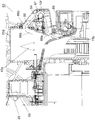
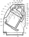
- FIG. 1 is a cross-sectional view showing the main configuration of the washing and drying machine according to Embodiment 1 of the present invention.
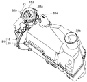
- FIG. 2 is an internal rear view showing the circulation air flow path and the outer tank back of the washing and drying machine.
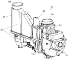
- FIG. 3 is a perspective view showing the inside of the heat pump blower unit of the washing and drying machine.
- FIG. 4 is a perspective view of a heat pump blower unit of the washer / dryer.
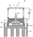
- FIG. 5 is a cross-sectional view showing the inside of the electrostatic atomization generator of the washing / drying machine.
- FIG. 6 is a perspective view showing the vicinity of the fixed plate of the atomizing discharge block of the washer / dryer.
- FIG. 7 is a cross-sectional view showing the inside of the atomizing discharge block of the washing / drying machine.
- FIG. 8 is a longitudinal sectional view of the washing and drying machine according to the second embodiment of the present invention.
- FIG. 9 is a longitudinal sectional view of another part of the washing / drying machine.
- FIG. 10 is another longitudinal sectional view of another part of the washing / drying machine.
- FIG. 1 is a cross-sectional view showing the main configuration of the washing and drying machine according to Embodiment 1 of the present invention
- FIG. 2 is an internal rear view showing the circulation air flow path and the outer tub back of the washing and drying machine
- FIG. It is a perspective view which shows the inside of the heat pump ventilation unit of a dryer.
- the washing tub 2 for storing the laundry is installed in the outer tub 3 so that the rotation axis direction is horizontal or inclined downward from the horizontal direction toward the rear.
- the washing / drying machine 1 includes a drying process in addition to washing, rinsing, and dehydration processes.
- the air in the outer tub 3 is sucked by the blower unit 15 through the circulation blower path 5, dehumidified and heated through the evaporator 31 and the condenser 32, and then repeatedly blown into the outer tub 3 for washing.
- the washing / drying machine 1 is equipped with a heat pump blower unit 81 connected in the middle of the circulation blower path 5.
- the heat pump blower unit 81 is configured by connecting the heat pump device 39 and the blower unit 15.
- the heat pump device 39 includes an evaporator 31 and a condenser 32 that are integrally formed, a compressor 37 that circulates a refrigerant through them, and the like.
- the heat pump device 39 is a heating device that heats the air in the outer tub 3.
- the blower unit 15 is a blower that pumps and circulates the air in the circulation blower path 5. By using the heat pump device 39 as the heating device, heating with high thermal efficiency can be performed.
- an opening portion 11 that is a clothing entrance leading to the opening end of the washing tub 2 is formed corresponding to the horizontal arrangement of the washing tub 2 or the illustrated inclination.
- the door 9 opens and closes the opening 11.
- the opening 11 is formed on the front side of the washing / drying machine main body 44 and is provided on the upward inclined surface.
- the washing and drying machine main body 44 that is a casing elastically supports the outer tub 3 by a suspension.
- the laundry can be taken in and out of the washing tub 2 by opening the door 9.
- the door 9 is provided on the upward inclined surface, the work for putting in and out the laundry can be performed without bending the waist.
- the washing tub 2 has a number of through holes 8 communicating with the outer tub 3 on its peripheral surface, and is provided with stirring protrusions 10 at a plurality of positions in the circumferential direction on the inner peripheral surface.
- the washing tub 2 is rotationally driven in the forward and reverse directions by a motor 7 attached to the rear side of the outer tub 3.
- a water injection pipe 12 and a drain pipe 13 are connected to the outer tub 3 by water, and water is poured into and drained from the outer tub 3 by controlling a water injection valve (not shown) and a drain valve. That is, a water supply apparatus including the water injection pipe 12, the water injection valve, and the like supplies washing water to the outer tub 3.
- the operation of the washing process will be described in order.
- the door 9 is opened, and laundry and detergent are put into the washing tub 2.
- the operation of the washing / drying machine 1 is started, for example, by an operation on the operation panel provided at the upper front of the washing / drying machine 1 through control by a control board or the like provided inside the operation panel.
- a predetermined amount of water is injected into the outer tub 3 from the water injection pipe 12, and the washing tub 2 is rotationally driven by the motor 7 to start the washing process.
- the washing tub 2 By the rotation of the washing tub 2, the laundry stored in the washing tub 2 is lifted in the rotation direction by the stirring protrusion 10 provided on the inner peripheral wall of the washing tub 2, and the stirring operation of dropping from the lifted appropriate height Is repeated. For this reason, the laundry is subjected to tapping and washing.
- the dirty washing liquid is discharged from the drain line 13. And the washing
- water is injected into the outer tub 3 from the water injection pipe 12 to carry out a rinsing process.
- the laundry stored in the washing tub 2 is repeatedly rinsed by the rotation of the washing tub 2 and the stirring operation of being lifted and dropped by the stirring protrusion 10.
- the rinsing process is finished, the water is drained and the laundry is drained by a dehydrating operation of rotating the washing tub 2 at a high speed to finish the washing.
- the door 9 is opened and the laundry is put into the washing tub 2.
- the operation is started through control by a control board or the like provided on the inside of the operation panel by an operation on an operation panel provided on the front upper portion of the washing / drying machine 1, for example.
- the air in the outer tub 3 is sucked through the circulation blower path 5 by the blower unit 15.
- the air in the outer tub 3 is passed through the filter box 5d to the evaporator 31 and the condenser 32, and is dehumidified and heated to be circulated and blown into the outer tub 3. While repeating this circulation, the moisture contained in the clothing is removed and the laundry is dried.
- the rotation mode and the stationary mode of the washing tub 2 can be selected according to the object to be dried.
- FIG. 4 is a perspective view of the heat pump blower unit of the washer / dryer according to Embodiment 1 of the present invention
- FIG. 5 is a sectional view showing the inside of the electrostatic atomization generator of the washer / dryer
- FIG. 6 is the washer / dryer.
- FIG. 7 is a cross-sectional view showing the inside of the atomizing discharge block of the washing / drying machine.
- the operation course of the washing / drying machine 1 includes a washing course in which only a washing process is performed, a drying course in which only drying is performed, a laundry drying course in which washing is continuously performed from drying to drying, and nanoe which performs sterilization and deodorization.
- a washing course in which only a washing process is performed
- a drying course in which only drying is performed
- a laundry drying course in which washing is continuously performed from drying to drying
- nanoe which performs sterilization and deodorization.
- the nano ecourse uses a circulation air passage 5 used in the air circulation in the outer tub 3 in the drying process.
- An electrostatic atomization generator 83 that generates electrostatic atomization generation particles 82 for realizing sterilization and deodorization is provided in the circulation air flow path 5.
- the rotation mode of the washing tub 2 and a stationary mode can be selected according to a target object, and driving
- the Nanoe tank clean mode that automatically exposes the electrostatic atomization generated particles 82 to the washing tub 2 and the outer tub 3 every time after taking out the clothes is installed, and the mode setting is turned on / off It is possible.
- the operation in the nanoe tank clean mode is performed while the washing tub 2 is stationary for about 60 minutes after the laundry course is completed and the door 9 is opened and closed.
- each of these hygiene-conscious courses is set to a course equivalent to washing and drying, and a dedicated operation button is also provided.
- the electrostatic atomization generating particles 82 have a strong oxidative decomposition ability that acts on the object. Therefore, simply by supplying the electrostatic atomization particles 82 without using heat as in the past, sterilization, deodorization, and mold growth control can be easily achieved without worrying about risks such as material deterioration. it can.
- the washing / drying machine 1 is provided with a special course for exposing the electrostatic atomization generating particles 82 to the stored items stored in the washing tub 2 or the surfaces of the washing tub 2 and the outer tub 3.
- the air blowing unit 15 is composed of a centrifugal fan in which a centrifugal type fan 15a is accommodated in a spiral casing 15b.
- the heat pump device 39 and the blower unit 15 are fitted in the suction connection port 15a of the spiral casing 15b with the suction / discharge port 38a, and are connected to each other in a sealing manner.
- the suction / discharge port 38 a is formed in the end wall on one end side in the left and right longitudinal directions of FIG. 3 of the heat pump case 38.
- the suction force of the blower unit 15 acts in the heat pump case 38.
- the suction force of the blower unit 15 acts in the outer tub 3 from the suction introduction port 38b through the suction passage 5a of the circulation blower passage 5 and the filter box 5d. Therefore, the air in the outer tub 3 is sucked into the heat pump case 38 and dehumidified and heated through the evaporator 31 and the condenser 32.
- the dried high-temperature air after dehumidification and heating is sucked into the spiral casing 15b through the suction discharge port 38a and the intake connection port 15c, and from the blowout portion 15d of the spiral casing 15b to the blower bellows connection portion 5b of the circulation blower path 5; The air is blown into the outer tub 3 through the air passage 5c. This is repeated to dry the laundry in the washing tub 2.
- the electrostatic atomization generator 83 is installed in the vicinity of the blowing part 15d.
- the suction inlet 38 b is disposed on the other end side of the heat pump case 38.
- the electrostatic atomization generator 83 is configured to connect the lead wires to the atomization discharge block 84, the transformer printed board 85, the control printed board 86, the element housing 87, the fixed plate 88, and the transformer printed board case 89.
- the transformer printed circuit board 85 generates a high voltage.
- the control printed circuit board 86 controls the atomizing discharge.
- the element housing 87 encloses the atomizing discharge block 84 and forms a bypass path 15f.
- the fixing plate 88 fixes the atomizing discharge block 84 and configures the inlet / outlet shape of the bypass path 15f.
- a transformer printed circuit board 85 is enclosed in the transformer printed circuit board case 89.
- electrostatic atomization generator 83 By installing the electrostatic atomization generator 83 in the circulation air flow path 5, electrostatic atomization is performed in the washing tub 2 and the outer tub 3 with little structural change by utilizing the operation during the drying operation. Generating particles 82 can be supplied. Moreover, the electrostatic atomization generation
- the aluminum heat exchange fin is attenuated by about 70%, and the aluminum fan 15a is attenuated by about 25%. Therefore, it is desirable to install the electrostatic atomization generator 83 in the vicinity of the outer tub 3 without using the aluminum heat exchange fins or the aluminum fan 15a.
- the electrostatic atomization generator 83 of the washing / drying machine 1 according to the first embodiment of the present invention is installed in the vicinity of the blowing unit 15 d of the blower unit 15. Therefore, the transmission loss of the electrostatic atomization generation
- the electrostatic atomization generator 83 is disposed on the side of the washer / dryer main body 44 cut from the movable part on the outer tub 3 side by the blower bellows connection part 5b. Thereby, durability reliability can be improved by not attaching the electrostatic atomization generator 83 which is a precise key device to the outer tank 3 side which vibrates at the time of dehydration.
- the electrostatic atomization generator 83 is configured integrally with a blowing portion 15 d which is a pressure air discharge side of the blower unit 15. Specifically, as shown in FIG. 5, an opening is provided on the wall surface of the spiral casing 15 b and the seal is fixed so as to be covered by the electrostatic atomization generator 83 including the bypass path 15 f. As a result, it is not necessary to newly provide the electrostatic atomization generator 83 in the circulation air flow path 5, and the system becomes simpler and less expensive, and further improves the assemblability and the man-hours. In addition, atomization and air blowing are effective only when integrated as functions, and it is desirable to unitize them.
- the electrostatic atomization generator 83 has a main flow path 15e and a bypass path 15f that merge after branching in two directions inside the unit, and the atomization discharge block 84 is disposed in the bypass path 15f. Yes. Thereby, generation
- the optimum air volume and speed for placing the electrostatic atomization generated particles 82 on the circulating air is the opening area of the fixed plate intake port 88a protruding into the bypass path 15f.
- the optimum wind speed for discharging the electrostatic atomization generating particles 82 is desirably around 1 m / s, and the opening amount of the fixed plate intake port 88a is designed in accordance with this.
- the exhaust side opening 88b portion of the fixed plate 88 winds in parallel with the flow direction of the circulating air in the circulation air flow path 5 to the main flow side path 15e at the junction of the bypass path 15f and the main flow side path 15e.
- a conducting plate 88c is disposed.
- the atomizing discharge block 84 includes a counter electrode 84b, a water supply device 84c, and a voltage application device 84d.
- the voltage application device 84d generates a high voltage between the discharge electrode 84a and the counter electrode 84b. When applied, the water supplied to the discharge electrode 84a is electrostatically atomized.
- the counter electrode 84b is disposed to face the discharge electrode 84a.
- the water supply device 84c supplies water to the discharge electrode 84a.
- Embodiment 1 of the present invention a negative voltage of 4.85 kV is applied between the discharge electrode 84a and the counter electrode 84b to electrostatically atomize water, and feedback is performed so that the discharge current value at that time is about 6 ⁇ A. Control is in progress.
- the discharge electrode 84a side becomes a negative electrode and charges are concentrated, and water attached to the surface of the discharge electrode 84a rises in a conical shape to form a Taylor cone. Then, the charge concentrates at the tip of the Taylor cone to become high density, and the Rayleigh splitting in which water splits and scatters as it is repelled by the repulsive force of the high density charge is repeated. At this time, the formation of the Taylor cone is affected by the wettability of the surface of the discharge electrode 84a. Therefore, if the wettability is low, the predetermined Taylor cone is not formed and electrostatic atomization cannot be performed. It is necessary to secure a predetermined amount.
- the water supply device 84c includes a cooling device including a Peltier element 84e.
- the discharge electrode 84a is cooled by this cooling device, and water is supplied by causing moisture (humidity) in the air to condense on the surface of the distal end portion of the discharge electrode 84a.
- the amount of water required for electrostatic atomization is about 0.5 ml / h.
- the end of the Peltier element 84e on the discharge electrode 84a side is a cooling portion 84f, and the opposite end is a heat dissipation portion 84g.
- the cooling part 84f is connected to the discharge electrode 84a, and the heat radiating part 84g is connected to the heat radiating fin 84h.
- the air flowing in the bypass path 15f of the electrostatic atomization generator 83 is configured to flow in contact with the heat radiating fins 84h, and this air flow is used for heat dissipation when atomizing discharge is performed.
- the necessary heat radiation amount during atomizing discharge is determined, and therefore the minimum required wind speed is determined by determining the heat-dissipating fins.
- 0.5 m / s or more is required, but a sufficient wind speed higher than that is ensured.
- the washer / dryer 1 has a negative pressure with respect to the atmospheric pressure when the air in the outer tub 3 is circulated via the circulation air passage 5.
- a first opening 51 is provided around the filter box 5d.
- the outside air intake section 5h is configured by connecting an opening / closing valve 5g and an outside air introduction duct 5e to the first opening 51.
- a second opening 52 is provided in a part of the circulation air passage 5 in the vicinity of the filter box 5d where the positive pressure or the dynamic pressure of the circulating air acts on the atmospheric pressure.
- the circulating air discharge duct 5f is connected to the 2nd opening part 52, and the circulating air discharge part 5i is comprised.
- the washing / drying machine 1 is designed to be highly airtight for drying, and if the door 9 is closed, there is almost no exchange of air between the outside of the machine and the inside of the tank. Since it is a washing machine, there is not a little water remaining, so the relative humidity in the tank when the door 9 is closed will soon exceed 90%.
- High humidity is not suitable as an environment for discharging, and even when the electrostatic atomization generator 83 is operated, the relative humidity in the tank needs to be 85% or less. Therefore, the abnormal discharge can be prevented from occurring by gradually replacing the air in the outer tub 3 with the outside air.
- the opening / closing valve 5g is opened and the air volume by the blower unit 15 is increased to actively replace the air in the outer tub 3 with the outside air.
- the opening / closing valve 5g is normally opened from the start of the course, and the dehumidifying operation is performed by operating the heat pump device 39 for about 2 minutes after 3 minutes from the start while replacing the air in the outer tub 3 with the outside air. To ensure operational stability.
- the electrostatic atomization generator 83 is operated together with the pressure of the circulating air in the circulating air passage 5 by the air blowing unit 15.
- grains 82 can be efficiently exposed to a target object.
- FIG. 8 is a longitudinal sectional view of the washing / drying machine according to Embodiment 2 of the present invention.
- description of the same configuration, operation, and effect as in the first embodiment will be omitted, and only different points will be described.
- a rotating drum 121 which is a washing tub of a drum type washing and drying machine, is formed in a bottomed cylindrical shape and is provided with a large number of through holes 122 on the entire outer periphery thereof, inside a water receiving tub 123 that is an outer tub. It is rotatably arranged.
- a rotation shaft 124 is provided at a rotational center of the rotating drum 121 so as to be inclined from the horizontal direction, and the axial center direction of the rotating drum 121 is inclined downward from the front side toward the back side.
- a motor 125 attached to the rear surface of the water receiving tank 123 is connected to the rotating shaft 124, and the rotating drum 121 is rotated in the forward and reverse directions.
- Several protruding plates 126 are provided on the inner wall surface of the rotating drum 121.
- the opening provided in the upward inclined surface on the front side of the water receiving tub 123 is covered with a lid 127 so as to be opened and closed, and by opening the lid 127, the laundry can be taken in and out of the rotary drum 121 through the clothing doorway 128. Yes. Since the lid 127 is provided on the upward inclined surface, the laundry can be carried out without bending the waist.
- the water receiving tank 123 is suspended from the washing / drying machine main body 129 by the spring body 130 and the damper 131 so as to be swingable.
- One end of the drainage path 132 is connected to the lower part of the water receiving tank 123, and the other end of the drainage path 132 is connected to the drain valve 133 so that the washing water in the water receiving tank 123 is drained.
- the water supply valve 134 supplies water into the water receiving tank 123 through the water supply path 135.
- the water level detection device 136 detects the water level in the water receiving tank 123.
- the rotation shaft 124 is provided at the rotation center of the rotating drum 121 from the horizontal direction, and the axial center direction of the rotating drum 121 is inclined downward from the front side to the back side.
- a rotating shaft 124 may be provided in the horizontal direction at the rotation center of the rotating drum 121, and the axial center direction of the rotating drum 121 may be disposed in the horizontal direction.
- FIG. 9 is a longitudinal sectional view of another part of the washing and drying machine according to the second embodiment of the present invention.
- the drying function includes a heater (heating device) 137, a blower fan (blower device) 138, and a fan case (part of the circulating air passage) 139 that accommodates the heater 137 and the blower fan 138 therein. Is attached to the washing and drying machine main body 129.
- the body portion of the water receiving tank 123 is provided with a hot air intake port (a part of the circulation air flow path) 140 for taking in air in the water receiving tank 123, and the hot air air blowing port 141 is provided on the back surface of the water receiving tank 123. ing.
- the water receiving tank 123 is integrally provided with a heat exchange path (a part of the circulating air blowing path) 142.
- One end of the heat exchange path 142 communicates with the hot air intake port 140, and the other end is connected to the intake end 139 a of the fan case 139 via a first bellows hose (part of the circulating air path) 143.
- the exhaust end 139 b of the fan case 139 communicates with the warm air blowing port 141 through the second bellows hose 145 and the back surface blowing path 144.
- the rear air blowing path 144 is provided integrally with the water receiving tank 123.
- a back surface through-hole 146 is provided on the back surface of the rotating drum 121 at a position corresponding to the hot air blowing port 141, and air from the hot air blowing port 141 is blown into the rotating drum 121.
- a plate-shaped heat exchange member 147 is attached above the hot air intake port 140 so as to be inclined downward from the front side toward the back side.
- the heat exchange path 142 is divided into a lower heat exchange path 142a and an upper heat exchange path 142b by a heat exchange member 147.
- the lower heat exchange path 142a and the upper heat exchange path 142b communicate with each other on the lower end portion 147b side of the heat exchange member 147 through the communication port 142c.
- the heat exchange path 142 is substantially U-shaped.
- the cooling water supply valve 148 adjusts the supply of cooling water from the water supply cap 150 to the upper end 147 a side of the heat exchange member 147 via the cooling water hose 149.
- the cooling water supply apparatus includes a cooling water supply valve 148, a cooling water hose 149, and a water supply base 150.
- the cross-sectional area of the upper heat exchange path 142b is larger than the cross-sectional area of the communication port 142c.
- the washing process, the rinsing process, the dehydrating process, and the drying process are executed by the control operation of the control device 151.
- the air blown by the rotation of the blower fan 138 is heated to a predetermined temperature by the heater 137 as indicated by the white arrow in FIG. Then, the air is blown into the water receiving tank 123 from the hot air blowing port 141 through the second bellows hose 145 and the back blowing path 144, and further blown into the rotating drum 121 from the back through hole 146.
- the heated hot air deprives moisture from the wet laundry in the rotating drum 121 and becomes hot air having moisture. Thereafter, the hot air having moisture passes through the through-hole 122 from the inside of the rotating drum 121, is discharged to the water receiving tank 123, and is further blown from the hot air intake port 140 to the heat exchange path 142.
- the cooling water supply valve 148 is open.
- the cooling water falls from the water supply cap 150 to the upper end 147a side of the heat exchange member 147, flows on the upper surface 147c of the heat exchange member 147 as indicated by the broken line arrow, and lower heat from the front end of the lower end 147b of the heat exchange member 147. It falls to the exchange path 142a side.
- the cooling water is provided on the bottom surface of the lower heat exchange path 142 a, is discharged into the water receiving tank 123 through the drain hole 152 communicating with the water receiving tank 123, and is discharged from the drum type washing and drying machine via the drainage path 132. To be discharged.
- the wet warm air sent from the hot air intake port 140 into the lower heat exchange path 142a of the heat exchange path 142 first comes into contact with the lower surface 147d of the heat exchange member 147.
- the lower surface 147d is also cooled by the cooling water flowing through the upper surface 147c of the heat exchange member 147, heat exchange is performed between the wet hot air and the lower surface 147d, and the wet hot air is dehumidified. (First dehumidification process).
- the humid hot air is sent to the upper heat exchange path 142b on the lower end 147b side of the heat exchange member 147 through the communication port 142c.
- the wet hot air rolls up and disperses the cooling water falling from the lower end portion 147b of the heat exchange member 147, heat exchange is performed with the scattered cooling water, and the wet hot air is dehumidified (second). Dehumidification process).
- the wet warm air is sent to the upper heat exchange path 142b, and comes into contact with the upper surface 147c of the heat exchange member 147 and the cooling water flowing therethrough.
- the direction in which the cooling water flows and the direction in which the wet warm air flows are opposed to each other.
- the wet warm air is heat-exchanged with the upper surface 147c of the heat exchange member 147 and the cooling water flowing therethrough, and the wet warm air is dehumidified (third dehumidification process).
- the humid hot air that has passed through the three dehumidifying processes of the first dehumidifying process, the second dehumidifying process, and the third dehumidifying process is efficiently cooled and dehumidified air. Then, the air is sent from the intake end 139 a of the fan case 139 into the fan case 139 via the first bellows hose 143 and reaches the blower fan 138.
- the cross-sectional area of the upper heat exchange path 142b is larger than the cross-sectional area of the communication port 142c. Therefore, the flow rate of the wet warm air in the upper heat exchange path 142b is lower than the flow rate in the communication port 142c. Therefore, the scattered cooling water rides on the warm air and falls onto the heat exchange member 147 in the middle of the upper heat exchange path 142b without entering the fan case 139 from the intake end 139a of the fan case 139. As a result, water drops do not reach the heater 137.
- an electrostatic atomization generator 83 is provided in a part of the circulation air flow path, upstream of the blower fan 138 and downstream of the intake end 139a, and an open / close valve 90 for taking in outside air is provided.
- the operation course of the washing / drying machine at the time of drying includes a washing course in which only the washing process is performed, a drying course in which only drying is performed, a laundry drying course in which washing is continuously performed from drying to There are four types of nano e-courses that perform bacteria and deodorization.
- Nano ecourse is an electrostatic atomization generating particle for realizing sterilization and deodorization in the middle of the circulation air flow path using the air circulation path used in the air circulation in the water receiving tank 123 in the drying process.
- An electrostatic atomization generator 83 for generating 82 is provided. Then, the on-off valve 90 is opened so that the upstream side of the blower fan 138 has a negative pressure, and the electrostatic atomization generator 83 blows air to the object in the rotary drum 121 without being adversely affected by the heat of the heater 137.
- This is a dedicated course for exposing the electrostatic atomization generating particles 82.
- the rotation mode and stationary mode of the rotating drum 121 can be selected according to the object, and the operation time is about 35 minutes.
- the nanoe tank clean mode in which the electrostatic atomization generation particles 82 are automatically exposed in the rotating drum 121 and the water receiving tank 123 each time is installed, and the mode setting is turned on. It can be turned off. The operation in this mode is performed while the rotary drum 121 is stationary for about 60 minutes after the laundry course is completed and the lid 127 is opened and closed.
- each of these hygiene-conscious courses is set to a course equivalent to washing and drying, and a dedicated operation button is also provided. Since the electrostatic atomization generating particles 82 have a strong oxidative decomposition ability that acts on the target, it is possible to easily realize sterilization, deodorization, and suppression of mold growth. Therefore, by setting it as a dedicated course, the user can easily select the optimum operation according to the purpose with peace of mind, improving usability.
- the laundry is gradually dried by the air circulation as described above, and the drying process is finished after a predetermined time has elapsed or when the laundry reaches a predetermined dryness.
- the flow rate of the wet warm air in the upper heat exchange path 142b is lower than the flow rate in the communication port 142c. Therefore, the splashed cooling water rides on the warm air and does not enter the fan case 139 or the electrostatic atomization generator 83 from the intake end 139a of the fan case 139, and into the cooling water in which the electrostatic atomization generated particles 82 are scattered. It is not absorbed. In the middle of the upper heat exchanging path 142b, the cooling water falls on the heat exchanging member 147, so that water droplets do not reach the heater 137.
- grains 82 can be exposed in the rotating drum 121 and the water receiving tank 123, without being absorbed by a water
- FIG. 10 is another longitudinal cross-sectional view of another part of the washing / drying machine of Embodiment 2 of the present invention.
- the electrostatic atomization generator 83 is provided in the vicinity of the hot air blowing port 141, it is hardly affected by the heat of the heater 137.
- the circulation air flow path is located above the water level stored in the water receiving tank 123, the water stored in the water receiving tank 123 is difficult to contact the electrostatic atomization generator 83. . Therefore, sufficient sterilization, deodorization, and mold growth suppression can be realized by the electrostatic atomization generating particles 82.
- a bypass path is provided in a part of the circulation air flow path, and an electrostatic atomization generator 83 is provided in the bypass path, so that the main stream at the junction of the bypass path and the main stream side path is provided.
- An air guide plate may be provided in the side path in parallel with the flow direction of the circulating air.
- the washing and drying machine of the present invention protects the laundry in the washing tub, the washing tub and the outer tub from the growth of fungi and mold by supplying electrostatic atomization generating particles to the washing tub and the outer tub. Can always be kept clean. Therefore, it can be applied to water facilities equipment that requires sterilization, mold suppression, and deodorization. In addition, it is suitable for household equipment because it does not incur running costs and is safe and harmless.
Abstract
洗濯物を収容する洗濯槽と、洗濯槽が回転可能に設置された外槽と、外槽を弾性支持する筐体と、外槽に洗濯水を供給する給水装置と、外槽内の空気を加熱する加熱装置と、外槽内の空気が加熱装置を経由して循環する循環送風経路と、循環送風経路内の空気を圧送して循環させる送風装置と、静電霧化発生粒子を洗濯槽および外槽内に供給するための静電霧化発生装置とを備え、静電霧化発生装置は循環送風経路内に配置された洗濯乾燥機。
Description
本発明は、洗濯乾燥機に関する。
近年、生活空間の衛生環境が着目され、除菌や消臭などを実現する衛生配慮商品が市場に多々流通している。ランドリー商品においても、衣類や布製品、革製品、玩具や小物などを除菌、消臭する機能を有する洗濯乾燥機が販売されている。
これらの洗濯乾燥機は一般に、洗濯槽内に対象物を投入し、数十分の運転を行う専用コースを設定している。具体的な除菌・消臭手段については、例えば槽内加熱、オゾン利用、薬剤使用など多岐にわたるが、基本は熱を加えることである。
また、洗濯機の槽内は菌、カビが発生し易い場所として危惧されてきた。これは、洗濯機には残水などによって多くの湿気を保持する。また、人が着衣を洗濯機駆動まで洗濯槽内に保持していることにより、着衣についた雑菌が槽内に入り込むことなどが原因である。更に、洗濯乾燥機の登場によって洗濯槽の気密性が高くなり、より保温性、保湿性が高まったことによる。
そこで、洗濯機には洗濯槽の菌、カビ対策を行う方法がいくつか提案されてきている。例えば洗濯槽内部を、ヒータなどの加熱手段を利用して十分に乾燥させる方法がある。しかしながら、利用者がいつのタイミング、頻度により洗濯槽の乾燥を行えば、効率的に防菌、防カビが可能になるかの判断がつかず、乾燥を頻繁に行うといった事態が生ずる。このように乾燥を利用する頻度が高くなると、多くの時間と電気代とを伴ってしまい、省エネルギーに反することとなる。従って、洗濯槽を乾燥させる方法は菌、カビ対策として良い事であると分かっていても、利用者に活用されない事が多い。
洗濯物および洗濯槽の菌、カビ対策の他の方法として、洗濯槽に使用する樹脂部品あるいは金属部品に抗菌成分を添加して除菌、防カビを行うこともある。例えば特許文献1には洗濯槽の表面を、有機系微生物繁殖抑制物質を配合した樹脂膜にて被覆することが記載されている。
また他の方法として、洗濯時に洗濯槽内部に除菌、防カビ成分を供給する方法も提案されている。例えば特許文献2にはすすぎ時にAgイオンを供給することにより衣類の除菌抗菌を行うとともに、洗濯槽に対する除菌、防カビを実施することが開示されている。
しかしながら、従来の熱を加え除菌、消臭を行う方法は利用者がいつのタイミング、頻度により洗濯槽の乾燥を行えば、防菌、防カビを効率的に行えるかの判断がつかず、乾燥を頻繁に行うといった課題がある。
また従来の除菌、消臭機能では熱を加えるため、熱ストレスへの配慮から対象物に制限があった。この場合、通常の乾燥機能と同等に多くの対象物が使用不可となり、かつ利用者が使用可能な対象物を判断するのは煩雑で難しい。また熱を長時間加えなければならないため、多くの電気を使用する。その他、水をミスト化して衣類に作用させる消臭手段などにおいても、水に濡らすことによる素材へのストレスが考えられる。
また特許文献1の洗濯機では、洗濯槽の表面に洗濯カス等が付着して、そこを起点に菌、カビが繁殖する場合がある。この場合、洗濯カス等の表面に菌、カビ等が繁殖するため、洗濯機の構成部品の抗菌成分が菌、カビ等に接触せず防菌効果を奏することができず、添加してもあまり効果的でないことが確認されている。
さらに特許文献2の洗濯機のように、防カビに必要なAgイオンを防菌の効果が出る程度に供給しようとすると、衣類が黒ずんだり等の洗浄効果そのものへの悪影響も危惧される。また、Agイオン発生にかかる費用も無視できなくなる。したがって洗濯物および洗濯槽の除菌、消臭に対し、より経済的な手段が要望されている。
本発明の洗濯乾燥機は、洗濯物を収容する洗濯槽と、洗濯槽が回転可能に設置された外槽と、外槽を弾性支持する筐体と、外槽に洗濯水を供給する給水装置と、外槽内の空気を加熱する加熱装置と、外槽内の空気が加熱装置を経由して循環する循環送風経路と、循環送風経路内の空気を圧送して循環させる送風装置と、静電霧化発生粒子を洗濯槽および外槽内に供給するための静電霧化発生装置とを備え、静電霧化発生装置は循環送風経路内に配置された構成である。
このような洗濯乾燥機は、乾燥時に使用される循環送風経路を利用して外槽に静電霧化発生粒子を供給することができ、洗濯物、洗濯槽の防菌、防カビを効率的に行える。この静電霧化発生粒子は、電気を帯びた微細な水分子の塊であり、酸化分解作用の高いラジカルを含んでいる。静電霧化発生装置によってこの静電霧化発生粒子を供給することにより、従来のように熱を使うことなく除菌、消臭、カビの発育抑制を実現できる。そして従来の除菌、消臭、カビ抑制の手段と違い、熱を使わないことによる低ランニングコストを実現できる。
本発明の実施の形態に係る洗濯乾燥機について、図を参照しながら以下に説明し本発明の理解に供する。なお以下の説明は本発明の具体例であって、特許請求の範囲の内容を限定するものではない。
(実施の形態1)
図1は本発明の実施の形態1の洗濯乾燥機の要部構成を示す断面図、図2は同洗濯乾燥機の循環送風経路と外槽背部とを示す内部背面図、図3は同洗濯乾燥機のヒートポンプ送風ユニットの内部を示す斜視図である。
図1は本発明の実施の形態1の洗濯乾燥機の要部構成を示す断面図、図2は同洗濯乾燥機の循環送風経路と外槽背部とを示す内部背面図、図3は同洗濯乾燥機のヒートポンプ送風ユニットの内部を示す斜視図である。
図1~図3に示すように洗濯乾燥機1において、洗濯物を収容する洗濯槽2は回転軸方向が水平または後部に向け水平方向から下向き傾斜となるよう回転可能に外槽3内に設置されている。洗濯乾燥機1では洗濯、すすぎ、脱水の各行程に加え、乾燥行程を備える。
乾燥行程は、送風ユニット15により循環送風経路5を通じ外槽3内の空気を吸引し、蒸発器31及び凝縮器32に通し除湿及び加熱した後、外槽3内に送風することを繰り返して洗濯物を乾燥させる行程である。この乾燥行程のために洗濯乾燥機1は、循環送風経路5の途中に接続したヒートポンプ送風ユニット81を搭載している。
ここでヒートポンプ送風ユニット81は、ヒートポンプ装置39と送風ユニット15とを接続して構成されている。またヒートポンプ装置39は、一体に構成された蒸発器31、凝縮器32及びそれらに冷媒を循環させる圧縮機37等から構成されている。このようにヒートポンプ装置39は、外槽3内の空気を加熱する加熱装置である。送風ユニット15は、循環送風経路5内の空気を圧送して循環させる送風装置である。加熱装置として、ヒートポンプ装置39を用いることにより、熱効率のよい加熱を行える。
外槽3の正面側には、洗濯槽2の水平配置ないしは図示する傾斜に対応して、洗濯槽2の開口端に通じる衣類出入口である開口部11が形成されている。扉9は、開口部11を開閉する。開口部11は、洗濯乾燥機本体44の正面側に形成され、上向き傾斜面に設けられている。また筐体である洗濯乾燥機本体44は、外槽3をサスペンションにより弾性支持している。
扉9を開くことにより、洗濯槽2内に対して洗濯物を出し入れすることができる。ここで扉9が上向き傾斜面に設けられているため、洗濯物を出し入れする作業を、腰を屈めることなく実施できる。
洗濯槽2には、その周面に外槽3内に通じる多数の透孔8が形成され、内周面の周方向複数位置に攪拌突起10が設けられている。洗濯槽2は、外槽3の後部側に取り付けられたモータ7によって正転及び逆転方向に回転駆動される。また外槽3には、注水管路12及び排水管路13が配管接続され、注水弁(図示せず)及び排水弁の制御によって外槽3内への注水及び排水がなされる。すなわち注水管路12、注水弁等から構成される給水装置は、外槽3に洗濯水を供給する。
洗濯行程の動作について、順に説明する。扉9を開き、洗濯槽2内に洗濯物及び洗剤を投入する。洗濯乾燥機1の例えば前面上部に設けられた操作パネルでの操作により、操作パネルの内側などに設けられた制御基板などによる制御を通じ、洗濯乾燥機1の運転を開始させる。外槽3内には注水管路12から所定量の注水がなされ、モータ7により洗濯槽2が回転駆動され、洗濯行程が開始される。洗濯槽2の回転により、洗濯槽2内に収容された洗濯物は洗濯槽2の内周壁に設けられた攪拌突起10によって回転方向に持ち上げられ、持ち上げられた適当な高さから落下する攪拌動作が繰り返される。そのため、洗濯物には叩き洗いの作用および洗浄がなされる。所要の洗濯時間の後、汚れた洗濯液は排水管路13から排出される。そして洗濯槽2を高速回転させる脱水動作により、洗濯物に含まれた洗濯液をしぼり出す。その後、外槽3内に注水管路12から注水してすすぎ行程が実施される。このすすぎ行程においても洗濯槽2内に収容された洗濯物は、洗濯槽2の回転および攪拌突起10により持ち上げられて落下する攪拌動作が繰り返され、すすぎが実施される。すすぎ行程が終わると排水され、洗濯槽2を高速回転させる脱水動作により洗濯物の水分を飛ばして洗濯を終了する。
次に、乾燥行程の動作について順に説明する。扉9を開き、洗濯槽2内に洗濯物を投入する。洗濯乾燥機1の例えば前面上部に設けられた操作パネルでの操作により、操作パネルの内側などに設けられた制御基板などによる制御を通じて運転を開始させる。外槽3内の空気は、送風ユニット15により循環送風経路5を通じ吸引される。そして外槽3内の空気は、フィルターボックス5dを経て蒸発器31及び凝縮器32に通し、除湿及び加熱した空気にして外槽3内に循環送風される。この循環を繰り返しながら、衣類に含まれた水分を取り、洗濯物を乾燥させる。乾燥行程においては、乾燥させる対象物に応じ、洗濯槽2の回転モード、静止モードを選択することができる。
図4は本発明の実施の形態1の洗濯乾燥機のヒートポンプ送風ユニットの斜視図、図5は同洗濯乾燥機の静電霧化発生装置の内部を示す断面図、図6は同洗濯乾燥機の霧化放電ブロックの固定板付近を示す斜視図、図7は同洗濯乾燥機の霧化放電ブロックの内部を示す断面図である。
本発明の実施の形態の洗濯乾燥機1の運転コースは、洗濯行程のみを行う洗濯コース、乾燥のみを行う乾燥コース、洗濯から乾燥まで連続で行う洗濯乾燥コース、除菌・消臭を行うナノイー(nanoe:パナソニック(株)の登録商標)コースの4種類の設定がある。図4、図7に示すようにナノイーコースとは、乾燥行程の外槽3内の空気循環において使用される循環送風経路5を利用している。循環送風経路5の途中に、除菌・消臭を実現するための静電霧化発生粒子82を発生させる静電霧化発生装置83を設けている。そして循環送風経路5から送風を行い、外槽3内および洗濯槽2内の対象物に静電霧化発生粒子82を曝露する。ナノイーコースについても、対象物に応じて洗濯槽2の回転モード、静止モードを選択することができ、運転時間は約35分である。
また、洗濯コースの終了後、衣類を取り出してから洗濯槽2および外槽3内に静電霧化発生粒子82を毎回自動にて曝露するナノイー槽クリーンモードを搭載し、モード設定をオン、オフ可能としている。ナノイー槽クリーンモードの運転は、洗濯コースが終了して扉9を開閉した後約60分間、洗濯槽2を静止したまま行われる。
本発明の実施の形態1における洗濯乾燥機1では、これら衛生配慮の各コースを洗濯、乾燥などと同等のコースに設定し、専用操作ボタンも設けている。静電霧化発生粒子82は、対象物に作用する強い酸化分解能力を有している。そのため、従来のように熱を使うことなく、静電霧化発生粒子82を供給するだけで、素材劣化などのリスクを気にすることなく除菌・消臭・カビの発育抑制を手軽に実現できる。このように洗濯乾燥機1は、静電霧化発生粒子82を洗濯槽2内に収納された収納物、または洗濯槽2および外槽3表面に曝露する専用コースを備えている。
よって専用コースとして設定することにより、目的にあわせた最適動作を使用者が簡単に安心して選ぶことができ、使い勝手が向上する。
循環送風経路5について詳しく説明すると、図3、図4に示すように送風ユニット15は、渦巻ケーシング15b内に遠心タイプのファン15aを収容した遠心ファンから構成されている。ヒートポンプ装置39と送風ユニット15とは、吸引排出口38aに渦巻ケーシング15bの吸気接続口15cを嵌め合わせ、互いをシール接続している。ここで吸引排出口38aは、ヒートポンプケース38の図3の左右の長手方向の一端側の端部壁に形成されている。
これにより、送風ユニット15の吸引力はヒートポンプケース38内に作用する。そして送風ユニット15の吸引力は、吸引導入口38bから循環送風経路5の吸引路5a、フィルターボックス5dを介し外槽3内に作用する。そのため外槽3内の空気は、ヒートポンプケース38内に吸引されて蒸発器31および凝縮器32を通して除湿および加熱される。除湿および加熱後の乾燥した高温空気は、吸引排出口38a、吸気接続口15cを通り渦巻ケーシング15b内に吸引され、渦巻ケーシング15bの吹き出し部15dから循環送風経路5の送風蛇腹接続部5b、および送風路5cを通り外槽3内に送風される。これを繰り返して洗濯槽2内の洗濯物を乾燥させる。静電霧化発生装置83は、吹き出し部15dの近傍に設置されている。吸引導入口38bは、ヒートポンプケース38の他端側に配置されている。
図5に示すように静電霧化発生装置83は、霧化放電ブロック84、トランスプリント基板85、制御プリント基板86、素子ハウジング87、固定板88、トランスプリント基板ケース89に、リード線結線を済ませてユニット化したものである。ここでトランスプリント基板85は、高圧を発生する。制御プリント基板86は、霧化放電を制御する。素子ハウジング87は、霧化放電ブロック84を封入しバイパス経路15fを形成する。固定板88は、霧化放電ブロック84を固定し、バイパス経路15fの入口出口形状を構成する。トランスプリント基板ケース89には、トランスプリント基板85が封入されている。
循環送風経路5内に静電霧化発生装置83を設置することにより、乾燥運転時の動作を利用し、構造的な変更をほとんど伴わずに洗濯槽2と外槽3とに静電霧化発生粒子82を供給することができる。また静電霧化発生粒子82は、気体のような拡散性が期待できず、循環送風経路5を流れる風に乗せて移動させ、対象物に曝露する必要がある。この時、ヒートポンプ装置39の蒸発器31および凝縮器32を形成するアルミニウム製熱交換フィン、送風ユニット15に使われるアルミニウム製のファン15aの羽根を通過すると、静電霧化発生粒子82は衝突して大量に消滅してしまいロスが大きくなってしまう。実測でもアルミニウム製熱交換フィンにおいて約70%、アルミニウム製のファン15aにおいて約25%減衰している。よってアルミニウム製熱交換フィンやアルミニウム製のファン15aを介さず、静電霧化発生装置83は外槽3近傍に設置することが望ましい。本発明の実施の形態1の洗濯乾燥機1の静電霧化発生装置83は、送風ユニット15の吹き出し部15d近傍に設置されている。そのため、静電霧化発生粒子82の洗濯槽2および外槽3への伝達ロスを最小限にし、より効率的に除菌・消臭・カビ抑制を行うことができる。
また静電霧化発生粒子82を洗濯槽2および外槽3へ曝露するコースにおいては、循環空気圧送と同時に静電霧化発生装置83を動作させる必要がある。上述したように、機能として霧化と送風とは一体にて初めて効果を発揮するものである。そのため送風手段の最適化された循環空気圧送により、静電霧化発生粒子82を効率よく対象物に曝露させることが必要不可欠となる。
また静電霧化発生装置83は、送風蛇腹接続部5bによって外槽3側の可動部から縁切りされた洗濯乾燥機本体44側に配置されている。これにより精密なキーデバイスである静電霧化発生装置83を、脱水時に振動する外槽3側に取り付けないことにより、耐久信頼性を高めることができる。
さらに図4に示すとおり静電霧化発生装置83は、送風ユニット15の圧送空気吐出側である吹き出し部15dと一体に構成されている。具体的には図5に示すとおり、渦巻ケーシング15bの壁面に開口部を設け、バイパス経路15fを含んだ静電霧化発生装置83により覆うようにしてシール固定したものである。これにより、静電霧化発生装置83を新たに循環送風経路5に配設する必要がなくなり、システムとしてより簡潔で安価な構成となる上に組立性向上、工数削減につながる。また機能として霧化と送風とは一体にして初めて効果を発揮するものであり、ユニット化しておくのが望ましい。
静電霧化発生装置83は、そのユニット内部において2方に分岐した後合流する本流側経路15eとバイパス経路15fとを有し、霧化放電ブロック84はそのバイパス経路15f内に配設されている。これにより、霧化放電ブロック84の放電部をバイパス経路15f内に直接突出させた構成のため危惧される風切り音の発生、循環風量の低下等を回避することができる。
また、バイパス経路15fへの分岐比率を最適化することにより、静電霧化発生粒子82を循環空気に乗せる最適な風量・風速は、バイパス経路15f内に突出する固定板吸気口88aの開口面積を変更して構造的に調整できる。本構成においては、静電霧化発生粒子82を放出するのに最適な風速は1m/s付近が望ましいので、これにあわせた固定板吸気口88aの開口量を設計している。
図6に示すとおり、固定板88の排気側開口88b部分は、バイパス経路15fと本流側経路15eとの合流部の本流側経路15eに、循環送風経路5の循環空気の流れ方向と平行に風導板88cが配置されている。風導板88cがない場合、一旦バイパス経路15fによって分岐された経路が再び合流する部分において、本流側経路15eの空気の流れに乱れが発生し全体の循環流量が低下し、騒音も増大する。また支流(バイパス経路15f)側の空気が、渦巻き状に回転して静電霧化発生粒子82を多量に消失してしまう。しかし合流部の本流側経路15eに循環空気の流れ方向と平行に風導板88cを配置することにより、これを防ぐことができる。
図7に示すように霧化放電ブロック84は、対向電極84b、水供給装置84c、および電圧印加装置84dを備え、電圧印加装置84dにて放電電極84aと対向電極84bとの間に高電圧を印加することにより放電電極84aに供給された水を静電霧化する。ここで対向電極84bは、放電電極84aに対向配置されている。水供給装置84cは、放電電極84aに水を供給する。
本発明の実施の形態1では放電電極84aと対向電極84bとの間に4.85kVの負電圧を印加して水を静電霧化させ、その時の放電電流値が約6μAとなるようにフィードバック制御を行っている。
静電霧化の過程は、高電圧の印加によって放電電極84a側が負電極となって電荷が集中するとともに放電電極84aの表面に付着した水が円錐形状に盛り上がってテイラーコーンが形成される。そしてテイラーコーンの先端に電荷が集中して高密度となり、高密度の電荷の反発力によりはじけるようにして水が分裂・飛散するレイリー分裂を繰り返す。この時、テイラーコーンの形成は放電電極84aの表面の濡れ性に影響されるので、濡れ性が小さいと所定のテイラーコーンが形成されず静電霧化できないため、放電電極84aの表面の水を所定量確保する必要がある。
水供給装置84cは、ペルチェ素子84eからなる冷却装置を備えている。この冷却装置にて放電電極84aを冷却させ、空気中の水分(湿気)を放電電極84aの先端部表面に結露させることにより水を供給する。ここで静電霧化に必要な水量は、0.5ml/h程度である。ペルチェ素子84eの放電電極84a側の端部が冷却部84f、その反対側の端部が放熱部84gとなっている。冷却部84fは放電電極84aに接続され、放熱部84gは放熱フィン84hに接続されている。
静電霧化発生装置83のバイパス経路15f内を流れる空気は、放熱フィン84hに接触させて流れるように構成し、霧化放電を行う時にはこの空気の流れを放熱に利用している。ペルチェ式の霧化放電ユニットの場合、霧化放電時の必要放熱量が決まるため、放熱用のフィンを決定すれば必要最低風速が決まる。本発明の実施の形態1の構成では0.5m/s以上が必要となるが、それ以上の十分な風速を確保している。放熱に循環送風経路5内を循環する空気を利用することにより、本来必要となる放熱装置を廃止することができる。
また図1、図2に示すように本発明の実施の形態1の洗濯乾燥機1は、循環送風経路5を経由して外槽3内の空気を循環する時、大気圧に対して負圧となるフィルターボックス5d周辺に第1の開口部51を設けている。機外空気取り込み部5hは、第1の開口部51に開閉弁5g、および外気導入ダクト5eが接続され構成されている。さらに、大気圧に対して正圧または循環空気の動圧が働くフィルターボックス5d近傍の循環送風経路5の一部に第2の開口部52を設けている。そして第2の開口部52に循環空気放出ダクト5fを接続し、循環空気吐き出し部5iを構成している。
開閉弁5gの開閉により、循環送風経路5の循環空気の一部を外気と入れ替えることができる。静電霧化発生粒子82を曝露する専用コースにおいては、少なくともその行程の初期段階だけでも開閉弁5gを開として、外槽3内の空気を機外空気と入れ替えが必要である。洗濯乾燥機1は乾燥を行うために気密性が高く設計され、扉9を閉めてしまえば機外と槽内との空気の入れ替わりはほとんどない。洗濯機である以上少なからず残水しているため、扉9を閉めた場合の槽内の相対湿度は90%をすぐに上回ってしまう。放電を行う環境として高湿度はふさわしくなく、静電霧化発生装置83を動作させる場合においても、槽内の相対湿度は85%以下が必要となる。そこで外槽3内の空気を外気と徐々に入れ替えることにより、異常放電が起こらないようにすることができる。
このように専用コースの初期において、開閉弁5gを開放するとともに送風ユニット15による風量を増加させ、外槽3内の空気を機外空気と積極的に入れ替える行程を有する。具体的には、コース開始から開閉弁5gを常時開とし、外槽3内の空気を機外空気と入れ替えながら、さらに開始3分後から約2分間、ヒートポンプ装置39を動作させて除湿運転を行い、動作安定性を確保している。
また専用コースは、送風ユニット15による循環送風経路5内の循環空気の圧送と共に静電霧化発生装置83を動作させる。このように霧化と送風とを同時に行うことにより、静電霧化発生粒子82を効率よく対象物に曝露することができる。
(実施の形態2)
図8は、本発明の実施の形態2の洗濯乾燥機の縦断面図である。本発明の実施の形態2では、実施の形態1と同様の構成、作用、効果については説明を省略し、異なる点のみ説明する。
図8は、本発明の実施の形態2の洗濯乾燥機の縦断面図である。本発明の実施の形態2では、実施の形態1と同様の構成、作用、効果については説明を省略し、異なる点のみ説明する。
図8に示すようにドラム式洗濯乾燥機の洗濯槽である回転ドラム121は、有底円筒形に形成し外周部に多数の透孔122を全面に設け、外槽である水受け槽123内に回転自在に配設されている。回転ドラム121の回転中心に水平方向から傾斜させて回転軸124を設け、回転ドラム121の軸心方向を正面側から背面側に向けて下向きに傾斜させて配設している。回転軸124に、水受け槽123の背面に取り付けたモータ125を連結し、回転ドラム121を正転、逆転方向に回転駆動する。回転ドラム121の内壁面には、数個の突起板126を設けている。
水受け槽123の正面側の上向き傾斜面に設けた開口部を蓋体127により開閉自在に覆い、蓋体127を開くことにより衣類出入口128を通して回転ドラム121内に洗濯物を出し入れできるようにしている。蓋体127を上向き傾斜面に設けているため、洗濯物を出し入れする際、腰を屈めることなく行うことができる。
水受け槽123は、洗濯乾燥機本体129よりばね体130とダンパー131とにより揺動可能に吊り下げられている。水受け槽123の下部に排水経路132の一端を接続し、排水経路132の他端を排水弁133に接続して水受け槽123内の洗濯水を排水するようにしている。給水弁134は、給水経路135を通して水受け槽123内に水を給水する。水位検知装置136は、水受け槽123内の水位を検知する。
なお、本発明の実施の形態2では、回転ドラム121の回転中心に水平方向から傾斜させて回転軸124を設け、回転ドラム121の軸心方向を正面側から背面側に向けて下向きに傾斜させて配設している。回転ドラム121の回転中心に水平方向に回転軸124を設け、回転ドラム121の軸心方向を水平方向に配設してもよい。
次に図9を用い、図8とは別の断面における乾燥機能の構成について説明する。図9は、本発明の実施の形態2の洗濯乾燥機の別の部位での縦断面図である。
乾燥機能は、ヒータ(加熱装置)137、送風ファン(送風装置)138、およびヒータ137と送風ファン138とを内部に収容するファンケース(循環送風経路の一部)139から構成され、ファンケース139は洗濯乾燥機本体129に取り付けられている。水受け槽123の胴部には、水受け槽123内の空気を取り入れる温風取入れ口(循環送風経路の一部)140を設け、水受け槽123の背面には温風送風口141を設けている。
また水受け槽123には、熱交換経路(循環送風経路の一部)142が一体に設けられている。熱交換経路142の一端は温風取入れ口140に連通し、他端は第1蛇腹ホース(循環送風経路の一部)143を介してファンケース139の吸気端139aに接続されている。ファンケース139の排気端139bは、第2蛇腹ホース145、背面送風経路144を介し温風送風口141に連通している。ここで背面送風経路144は、水受け槽123に一体に設けられている。
また、回転ドラム121の背面には、温風送風口141と対応する位置に背面透孔146が設けられ、温風送風口141からの送風が回転ドラム121内に送風される。
熱交換経路142には、温風取入れ口140の上方に正面側から背面側に向けて下向きに傾斜させて板状の熱交換部材147が取り付けられている。熱交換経路142は、熱交換部材147により下部熱交換経路142aと上部熱交換経路142bとに分割されている。下部熱交換経路142aと上部熱交換経路142bとは、連通口142cを介して熱交換部材147の下端部147b側において連通している。熱交換経路142は、略U字状である。冷却用給水弁148は、冷却水ホース149を介し給水口金部150から熱交換部材147の上端部147a側への冷却水の給水を調節する。冷却水給水装置は、冷却用給水弁148、冷却水ホース149、および給水口金部150により構成されている。また上部熱交換経路142bの断面積は、連通口142cの断面積より大きくしている。
上記構成のドラム式洗濯乾燥機は、制御装置151による制御動作により洗濯行程、すすぎ行程、脱水行程および乾燥行程が実行される。
次に、上記構成のドラム式洗濯乾燥機の動作を説明する。なお洗濯行程から脱水行程までの動作は、従来の洗濯乾燥機の動作と同じであるので説明を省略する。
乾燥行程において、図9の白抜き矢印にて示すように送風ファン138の回転により送風された空気は、ヒータ137によって所定温度に加熱される。そして第2蛇腹ホース145および背面送風経路144を介し、温風送風口141から水受け槽123内に送風され、さらに背面透孔146から回転ドラム121内に送風される。その加熱された温風は、回転ドラム121内の撹拌されている状態の湿った洗濯物から水分を奪い、湿気を有する温風となる。その後、湿気を有する温風は、回転ドラム121内から透孔122を通り、水受け槽123に排出され、さらに温風取入れ口140から熱交換経路142に送風される。
このとき、冷却用給水弁148は開状態となっている。冷却水は給水口金部150から熱交換部材147の上端部147a側に落下し、破線矢印のように熱交換部材147の上面147cを流れ、熱交換部材147の下端部147bの先端部から下部熱交換経路142a側に落下する。その後、その冷却水は下部熱交換経路142aの底面に設けられ、水受け槽123と連通した水抜き穴152から水受け槽123内に排出され、排水経路132を介してドラム式洗濯乾燥機外に排出される。
温風取入れ口140から熱交換経路142の下部熱交換経路142a内に送られた湿った温風は、まず熱交換部材147の下面147dと接触する。このとき、熱交換部材147の上面147cを流れている冷却水により下面147dも冷却されているので、湿った温風と下面147dとの間において熱交換が行われ、湿った温風は除湿される(第1除湿行程)。
さらに湿った温風は、連通口142cを介し熱交換部材147の下端部147b側において上部熱交換経路142bに送られる。その際湿った温風は、熱交換部材147の下端部147bから落下する冷却水を巻き上げて飛散させ、その飛散した冷却水と熱交換が行われ、湿った温風は除湿される(第2除湿行程)。
その後、湿った温風は上部熱交換経路142bに送られ、熱交換部材147の上面147c、およびそこを流れる冷却水と接触する。このとき、冷却水の流れる方向と湿った温風が流れる方向とは対向している。これにより、湿った温風は、熱交換部材147の上面147c、およびそこを流れる冷却水と熱交換が行われ、湿った温風は除湿される(第3除湿行程)。
このように第1除湿行程、第2除湿行程、および第3除湿行程の3つの除湿行程を経た湿った温風は、効率よく冷却され除湿された空気となる。そして第1蛇腹ホース143を介し、ファンケース139の吸気端139aからファンケース139内に送られ、送風ファン138に至る。
また上記行程において、上部熱交換経路142bの断面積は、連通口142cの断面積より大きくしている。そのため、湿った温風の上部熱交換経路142bにおける流速は、連通口142cにおける流速より低下する。そのため飛散した冷却水はその温風に乗り、ファンケース139の吸気端139aからファンケース139内まで入り込むことなく、上部熱交換経路142bの途中において熱交換部材147上に落下する。その結果、水滴がヒータ137までたどり着くことはない。
図9では、循環送風経路の一部に送風ファン138の上流であって、吸気端139aの下流に静電霧化発生装置83を設け、外気を取り込むための開閉弁90が設けられている。本発明の第1の実施の形態と同様、乾燥時の洗濯乾燥機の運転コースは、洗濯行程のみを行う洗濯コース、乾燥のみを行う乾燥コース、洗濯から乾燥まで連続で行う洗濯乾燥コース、除菌・消臭を行うナノイーコースの4種類がある。ナノイーコースとは、乾燥行程の水受け槽123内の空気循環において使用される循環送風経路を利用して、循環送風経路の途中に除菌・消臭を実現するための静電霧化発生粒子82を発生させる静電霧化発生装置83を設けている。そして開閉弁90を開弁して送風ファン138の上流が負圧となり、静電霧化発生装置83がヒータ137の熱による悪影響を受けることなく、送風することにより回転ドラム121内の対象物に静電霧化発生粒子82を曝露する専用コースである。このコースについても、対象物に応じて回転ドラム121の回転モード、静止モードを選択することができ、運転時間は約35分である。
また、洗濯コースの終了後、衣類を取り出してから回転ドラム121および水受け槽123内に静電霧化発生粒子82を毎回自動にて曝露するナノイー槽クリーンモードを搭載し、モード設定をオン、オフ可能としている。このモードの運転は、洗濯コースが終了して蓋体127を開閉した後に、約60分間回転ドラム121を静止したまま行われる。
本発明の実施の形態2の洗濯乾燥機では、これら衛生配慮の各コースを洗濯、乾燥などと同等のコースに設定し、専用操作ボタンも設けている。静電霧化発生粒子82は、対象物に作用する強い酸化分解能力を有しているため、除菌・消臭・カビの発育抑制を手軽に実現できる。よって専用コースとして設定することにより、目的にあわせた最適動作を使用者が簡単に安心して選ぶことができ、使い勝手が向上する。
上記のような空気の循環により、洗濯物は徐々に乾燥され、所定時間経過後、または洗濯物が所定の乾燥度になると乾燥行程を終了する。
以上のように、本発明の実施の形態2においては乾燥行程時に、湿った温風の上部熱交換経路142bにおける流速は、連通口142cにおける流速より低下する。そのため飛散した冷却水はその温風に乗り、ファンケース139の吸気端139aからファンケース139内や静電霧化発生装置83まで入り込むことなく、静電霧化発生粒子82が飛散した冷却水に吸収されることもない。そして上部熱交換経路142bの途中において、冷却水は熱交換部材147上に落下するので、水滴がヒータ137までたどり着くことはない。そのため、ヒータ137に水が付着して不安全な状態となるのを防止することができ、安全性を確保しながら湿気を有する空気の除湿を効率的に行う。また静電霧化発生粒子82が水分に吸収されることなく、回転ドラム121および水受け槽123内に静電霧化発生粒子82を曝露することができる。
次に図10は、本発明の実施の形態2の洗濯乾燥機の別の部位での他の縦断面図である。図10では、温風送風口141近傍に静電霧化発生装置83を設けているためヒータ137の熱による影響を受けにくい。また循環送風経路は水受け槽123内に溜められる水位よりも上方に位置しているので、水受け槽123内に溜められる水が静電霧化発生装置83に接触しにくい構成となっている。そのため静電霧化発生粒子82により、十分な除菌・消臭・カビの発育抑制を実現できる。
また本発明の実施の形態1のように、循環送風経路の一部にバイバス経路を設けるとともに、バイパス経路に静電霧化発生装置83を設け、バイパス経路と本流側経路との合流部の本流側経路に、循環空気の流れ方向と平行に風導板を設けてもよい。
以上のように、本発明の洗濯乾燥機は、洗濯槽と外槽に静電霧化発生粒子を供給することによって洗濯槽内の洗濯物、洗濯槽および外槽を菌、カビの繁殖から守り、常に清潔な状態に維持することができる。よって除菌・カビ抑制、消臭が必要な水回り設備機器などに適用できる。またランニングコストがかからず安全無害のため、家庭用機器に適する。
1 洗濯乾燥機
2 洗濯槽
3 外槽
5 循環送風経路
5a 吸引路
5b 送風蛇腹接続部
5c 送風路
5d フィルターボックス
5e 外気導入ダクト
5f 循環空気放出ダクト
5g 開閉弁
7,125 モータ
8,122 透孔
9 扉
10 攪拌突起
11 開口部
12 注水管路
13 排水管路
15 送風ユニット
15a ファン
15b 渦巻ケーシング
15c 吸気接続口
15d 吹き出し部
31 蒸発器
32 凝縮器
37 圧縮機
38 ヒートポンプケース
38a 吸引排出口
38b 吸引導入口
39 ヒートポンプ装置
44,129 洗濯乾燥機本体
51 第1の開口部
52 第2の開口部
81 ヒートポンプ送風ユニット
82 静電霧化発生粒子
83 静電霧化発生装置
84 霧化放電ブロック
84a 放電電極
84b 対向電極
84c 水供給装置
84d 電圧印加装置
84e ペルチェ素子
84f 冷却部
84g 放熱部
84h 放熱フィン
85 トランスプリント基板
86 制御プリント基板
87 素子ハウジング
88a 固定板吸気口
88b 排気側開口
88c 風導板
89 トランスプリント基板ケース
90 開閉弁
121 回転ドラム
123 水受け槽
124 回転軸
126 突起板
127 蓋体
128 衣類出入口
130 ばね体
131 ダンパー
132 排水経路
133 排水弁
134 給水弁
135 給水経路
136 水位検知装置
137 ヒータ
138 送風ファン
139 ファンケース
139a 吸気端
139b 排気端
140 温風取入れ口
141 温風送風口
142 熱交換経路
142a 下部熱交換経路
142b 上部熱交換経路
142c 連通口
143 第1蛇腹ホース
144 背面送風経路
145 第2蛇腹ホース
146 背面透孔
147 熱交換部材
147a 上端部
147b 下端部
147c 上面
147d 下面
148 冷却用給水弁
149 冷却水ホース
150 給水口金部
151 制御装置
152 水抜き穴
Claims (10)
- 洗濯物を収容する洗濯槽と、前記洗濯槽が回転可能に設置された外槽と、前記外槽を弾性支持する筐体と、前記外槽に洗濯水を供給する給水装置と、前記外槽内の空気を加熱する加熱装置と、前記外槽内の空気が前記加熱装置を経由して循環する循環送風経路と、前記循環送風経路内の空気を圧送して循環させる送風装置と、静電霧化発生粒子を前記洗濯槽および前記外槽内に供給するための静電霧化発生装置とを備え、前記静電霧化発生装置は前記循環送風経路内に配置されたことを特徴とする洗濯乾燥機。
- 前記加熱装置が圧縮機、蒸発器、凝縮器を収容したヒートポンプ装置であることを特徴とする請求項1記載の洗濯乾燥機。
- 前記静電霧化発生装置は、前記循環送風経路内の循環空気が前記加熱装置および前記送風装置を通過し前記外槽に吹き出される吹き出し部近傍に配置されたことを特徴とする請求項1または2のいずれか一項に記載の洗濯乾燥機。
- 前記静電霧化発生装置は、前記吹き出し部と一体に構成されたことを特徴とする請求項3に記載の洗濯乾燥機。
- 前記静電霧化発生装置は、前記筐体側に配置されたことを特徴とする請求項1または2のいずれか一項に記載の洗濯乾燥機。
- 前記静電霧化発生装置は2方に分岐した後合流する本流側経路とバイパス経路とを有し、前記静電霧化発生装置を構成する霧化放電ブロックが前記バイパス経路内に配置されたことを特徴とする請求項1または2のいずれか一項に記載の洗濯乾燥機。
- 前記バイパス経路と前記本流側経路との合流部の前記本流側経路に、前記循環送風経路内の循環空気の流れ方向と平行に風導板を配置したことを特徴とする請求項6に記載の洗濯乾燥機。
- 前記静電霧化発生装置は、放電電極と、前記放電電極に高電圧を印加するための電圧印加装置と、前記放電電極に水を供給する水供給装置とから構成され、前記水供給装置は前記放電電極を冷却し空気中の水分を結露させて前記放電電極に結露水を生成させるペルチェ素子と、吸熱した熱を放出するための放熱フィンとを備え、前記バイパス経路内を流れる空気を前記放熱フィンに接触させて放熱に利用することを特徴とする請求項6に記載の洗濯乾燥機。
- 前記洗濯槽内に収納された収納物または前記洗濯槽および前記外槽表面に前記静電霧化発生粒子を曝露する専用コースを有することを特徴とする請求項1または2のいずれか一項に記載の洗濯乾燥機。
- 前記専用コースは、前記送風装置による前記循環送風経路内の循環空気の圧送と共に前記静電霧化発生装置を動作させることを特徴とする請求項9に記載の洗濯乾燥機。
Priority Applications (2)
| Application Number | Priority Date | Filing Date | Title |
|---|---|---|---|
| CN2009801356839A CN102149865B (zh) | 2008-09-12 | 2009-09-01 | 洗涤干燥机 |
| EP09812852.3A EP2319979B1 (en) | 2008-09-12 | 2009-09-01 | Washing and drying machine |
Applications Claiming Priority (8)
| Application Number | Priority Date | Filing Date | Title |
|---|---|---|---|
| JP2008-234682 | 2008-09-12 | ||
| JP2008-234684 | 2008-09-12 | ||
| JP2008234684 | 2008-09-12 | ||
| JP2008234682 | 2008-09-12 | ||
| JP2008-315359 | 2008-12-11 | ||
| JP2008315359A JP5083192B2 (ja) | 2008-09-12 | 2008-12-11 | 洗濯乾燥機 |
| JP2008315361A JP5098986B2 (ja) | 2008-09-12 | 2008-12-11 | 洗濯乾燥機 |
| JP2008-315361 | 2008-12-11 |
Publications (1)
| Publication Number | Publication Date |
|---|---|
| WO2010029703A1 true WO2010029703A1 (ja) | 2010-03-18 |
Family
ID=42497891
Family Applications (1)
| Application Number | Title | Priority Date | Filing Date |
|---|---|---|---|
| PCT/JP2009/004280 WO2010029703A1 (ja) | 2008-09-12 | 2009-09-01 | 洗濯乾燥機 |
Country Status (4)
| Country | Link |
|---|---|
| EP (1) | EP2319979B1 (ja) |
| CN (2) | CN102149865B (ja) |
| TW (1) | TWI383080B (ja) |
| WO (1) | WO2010029703A1 (ja) |
Cited By (4)
| Publication number | Priority date | Publication date | Assignee | Title |
|---|---|---|---|---|
| JP2011200372A (ja) * | 2010-03-25 | 2011-10-13 | Panasonic Corp | 電気掃除機 |
| JP2014140526A (ja) * | 2013-01-24 | 2014-08-07 | Toshiba Corp | 洗濯乾燥機 |
| CN113605044A (zh) * | 2020-10-26 | 2021-11-05 | 松下家电(中国)有限公司 | 衣物护理设备的控制方法 |
| JP7445837B2 (ja) | 2020-10-26 | 2024-03-08 | パナソニックIpマネジメント株式会社 | 衣類処理装置 |
Families Citing this family (8)
| Publication number | Priority date | Publication date | Assignee | Title |
|---|---|---|---|---|
| CN102149865B (zh) * | 2008-09-12 | 2013-12-04 | 松下电器产业株式会社 | 洗涤干燥机 |
| JP6362830B2 (ja) * | 2012-08-23 | 2018-07-25 | 東芝ライフスタイル株式会社 | 家電機器 |
| EP2948582B1 (en) | 2013-01-25 | 2022-03-02 | LG Electronics Inc. | Laundry treatment apparatus |
| KR101995429B1 (ko) * | 2013-01-25 | 2019-07-02 | 엘지전자 주식회사 | 의류처리장치 |
| JP2017189484A (ja) * | 2016-04-15 | 2017-10-19 | 日立アプライアンス株式会社 | 洗濯乾燥機 |
| JP7450172B2 (ja) * | 2017-09-28 | 2024-03-15 | パナソニックIpマネジメント株式会社 | 食器洗い機 |
| JP7209142B2 (ja) * | 2018-07-13 | 2023-01-20 | パナソニックIpマネジメント株式会社 | 食器乾燥機 |
| JP7042446B2 (ja) * | 2018-10-05 | 2022-03-28 | パナソニックIpマネジメント株式会社 | 食器洗い機 |
Citations (6)
| Publication number | Priority date | Publication date | Assignee | Title |
|---|---|---|---|---|
| JPH08252392A (ja) | 1996-04-08 | 1996-10-01 | Hitachi Ltd | 洗濯機 |
| JP2001276484A (ja) | 2000-03-30 | 2001-10-09 | Toto Ltd | 洗濯機 |
| JP2003135889A (ja) * | 2001-11-08 | 2003-05-13 | Sharp Corp | 乾燥洗濯機 |
| JP2005192901A (ja) * | 2004-01-09 | 2005-07-21 | Sanyo Electric Co Ltd | 洗濯機 |
| JP2006029663A (ja) * | 2004-07-15 | 2006-02-02 | Matsushita Electric Ind Co Ltd | 空気調和機 |
| JP2008194265A (ja) * | 2007-02-14 | 2008-08-28 | Matsushita Electric Ind Co Ltd | ドラム式洗濯乾燥機 |
Family Cites Families (8)
| Publication number | Priority date | Publication date | Assignee | Title |
|---|---|---|---|---|
| JP2002018186A (ja) * | 2000-07-07 | 2002-01-22 | Hitachi Ltd | 洗濯機及びその運転方法 |
| JP2002239285A (ja) * | 2001-02-16 | 2002-08-27 | Nippon Kentetsu Co Ltd | 全自動一槽式洗濯機 |
| US20030126691A1 (en) * | 2001-12-20 | 2003-07-10 | Gerlach Christian Gerhard Friedrich | Fabric article treating method and apparatus |
| JP2005198860A (ja) * | 2004-01-16 | 2005-07-28 | Sanyo Electric Co Ltd | 洗濯機 |
| JP4679384B2 (ja) * | 2006-02-10 | 2011-04-27 | 株式会社東芝 | 洗濯乾燥機 |
| JP4656051B2 (ja) * | 2006-12-15 | 2011-03-23 | パナソニック電工株式会社 | 静電霧化装置 |
| JP4893344B2 (ja) * | 2007-01-31 | 2012-03-07 | パナソニック電工株式会社 | ファンヒータ |
| CN102149865B (zh) * | 2008-09-12 | 2013-12-04 | 松下电器产业株式会社 | 洗涤干燥机 |
-
2009
- 2009-09-01 CN CN2009801356839A patent/CN102149865B/zh active Active
- 2009-09-01 EP EP09812852.3A patent/EP2319979B1/en not_active Not-in-force
- 2009-09-01 WO PCT/JP2009/004280 patent/WO2010029703A1/ja active Application Filing
- 2009-09-07 TW TW098130066A patent/TWI383080B/zh active
- 2009-09-11 CN CN200920177872XU patent/CN201517170U/zh not_active Expired - Fee Related
Patent Citations (6)
| Publication number | Priority date | Publication date | Assignee | Title |
|---|---|---|---|---|
| JPH08252392A (ja) | 1996-04-08 | 1996-10-01 | Hitachi Ltd | 洗濯機 |
| JP2001276484A (ja) | 2000-03-30 | 2001-10-09 | Toto Ltd | 洗濯機 |
| JP2003135889A (ja) * | 2001-11-08 | 2003-05-13 | Sharp Corp | 乾燥洗濯機 |
| JP2005192901A (ja) * | 2004-01-09 | 2005-07-21 | Sanyo Electric Co Ltd | 洗濯機 |
| JP2006029663A (ja) * | 2004-07-15 | 2006-02-02 | Matsushita Electric Ind Co Ltd | 空気調和機 |
| JP2008194265A (ja) * | 2007-02-14 | 2008-08-28 | Matsushita Electric Ind Co Ltd | ドラム式洗濯乾燥機 |
Non-Patent Citations (1)
| Title |
|---|
| See also references of EP2319979A4 * |
Cited By (4)
| Publication number | Priority date | Publication date | Assignee | Title |
|---|---|---|---|---|
| JP2011200372A (ja) * | 2010-03-25 | 2011-10-13 | Panasonic Corp | 電気掃除機 |
| JP2014140526A (ja) * | 2013-01-24 | 2014-08-07 | Toshiba Corp | 洗濯乾燥機 |
| CN113605044A (zh) * | 2020-10-26 | 2021-11-05 | 松下家电(中国)有限公司 | 衣物护理设备的控制方法 |
| JP7445837B2 (ja) | 2020-10-26 | 2024-03-08 | パナソニックIpマネジメント株式会社 | 衣類処理装置 |
Also Published As
| Publication number | Publication date |
|---|---|
| CN102149865A (zh) | 2011-08-10 |
| TWI383080B (zh) | 2013-01-21 |
| CN201517170U (zh) | 2010-06-30 |
| TW201026921A (en) | 2010-07-16 |
| CN102149865B (zh) | 2013-12-04 |
| EP2319979B1 (en) | 2013-06-05 |
| EP2319979A4 (en) | 2012-05-30 |
| EP2319979A1 (en) | 2011-05-11 |
Similar Documents
| Publication | Publication Date | Title |
|---|---|---|
| WO2010029703A1 (ja) | 洗濯乾燥機 | |
| JP5447587B2 (ja) | 洗濯乾燥機 | |
| EP1445367B1 (en) | Drying/washing machine | |
| JP4504388B2 (ja) | ドラム式洗濯乾燥機 | |
| JP5012938B2 (ja) | 洗濯乾燥機 | |
| JP4893714B2 (ja) | 洗濯機 | |
| JP5012937B2 (ja) | 洗濯乾燥機 | |
| JP5447586B2 (ja) | 洗濯乾燥機 | |
| CN101671935B (zh) | 洗涤烘干机 | |
| JP4499769B2 (ja) | ドラム式洗濯乾燥機 | |
| JP4655143B2 (ja) | 洗濯乾燥機 | |
| JP2011067298A (ja) | 乾燥機 | |
| JP5306148B2 (ja) | 洗濯乾燥機 | |
| JP2004350840A (ja) | 洗濯機および洗濯乾燥機 | |
| JP5039081B2 (ja) | ミスト発生装置及び洗濯乾燥機 | |
| JP2020185315A (ja) | 衣類乾燥機 | |
| WO2024029443A1 (ja) | 洗濯機、洗濯乾燥機、及び洗濯機の外槽の除菌方法 | |
| JP4930614B2 (ja) | 洗濯乾燥機 | |
| WO2024029444A1 (ja) | 洗濯機及び洗濯機の外槽の除菌方法 | |
| JP5845410B2 (ja) | 洗濯乾燥機 | |
| JP5857199B2 (ja) | 洗濯乾燥機 | |
| JP2023080773A (ja) | 衣類処理装置 | |
| JP2017070540A (ja) | 衣類処理装置 | |
| JP2009089961A (ja) | ドラム式洗濯乾燥機 |
Legal Events
| Date | Code | Title | Description |
|---|---|---|---|
| WWE | Wipo information: entry into national phase |
Ref document number: 200980135683.9 Country of ref document: CN |
|
| 121 | Ep: the epo has been informed by wipo that ep was designated in this application |
Ref document number: 09812852 Country of ref document: EP Kind code of ref document: A1 |
|
| WWE | Wipo information: entry into national phase |
Ref document number: 2009812852 Country of ref document: EP |
|
| NENP | Non-entry into the national phase |
Ref country code: DE |