WO2009119771A1 - 積層型固体酸化物形燃料電池用スタック構造体、積層型固体酸化物形燃料電池及びその製造方法 - Google Patents
積層型固体酸化物形燃料電池用スタック構造体、積層型固体酸化物形燃料電池及びその製造方法 Download PDFInfo
- Publication number
- WO2009119771A1 WO2009119771A1 PCT/JP2009/056188 JP2009056188W WO2009119771A1 WO 2009119771 A1 WO2009119771 A1 WO 2009119771A1 JP 2009056188 W JP2009056188 W JP 2009056188W WO 2009119771 A1 WO2009119771 A1 WO 2009119771A1
- Authority
- WO
- WIPO (PCT)
- Prior art keywords
- stack structure
- separator
- solid electrolyte
- electrode layer
- air electrode
- Prior art date
Links
Images


Classifications
-
- H—ELECTRICITY
- H01—ELECTRIC ELEMENTS
- H01M—PROCESSES OR MEANS, e.g. BATTERIES, FOR THE DIRECT CONVERSION OF CHEMICAL ENERGY INTO ELECTRICAL ENERGY
- H01M8/00—Fuel cells; Manufacture thereof
- H01M8/24—Grouping of fuel cells, e.g. stacking of fuel cells
- H01M8/241—Grouping of fuel cells, e.g. stacking of fuel cells with solid or matrix-supported electrolytes
- H01M8/2425—High-temperature cells with solid electrolytes
- H01M8/2432—Grouping of unit cells of planar configuration
-
- H—ELECTRICITY
- H01—ELECTRIC ELEMENTS
- H01M—PROCESSES OR MEANS, e.g. BATTERIES, FOR THE DIRECT CONVERSION OF CHEMICAL ENERGY INTO ELECTRICAL ENERGY
- H01M8/00—Fuel cells; Manufacture thereof
- H01M8/02—Details
- H01M8/0271—Sealing or supporting means around electrodes, matrices or membranes
- H01M8/0276—Sealing means characterised by their form
-
- H—ELECTRICITY
- H01—ELECTRIC ELEMENTS
- H01M—PROCESSES OR MEANS, e.g. BATTERIES, FOR THE DIRECT CONVERSION OF CHEMICAL ENERGY INTO ELECTRICAL ENERGY
- H01M8/00—Fuel cells; Manufacture thereof
- H01M8/02—Details
- H01M8/0202—Collectors; Separators, e.g. bipolar separators; Interconnectors
- H01M8/0258—Collectors; Separators, e.g. bipolar separators; Interconnectors characterised by the configuration of channels, e.g. by the flow field of the reactant or coolant
- H01M8/0263—Collectors; Separators, e.g. bipolar separators; Interconnectors characterised by the configuration of channels, e.g. by the flow field of the reactant or coolant having meandering or serpentine paths
-
- H—ELECTRICITY
- H01—ELECTRIC ELEMENTS
- H01M—PROCESSES OR MEANS, e.g. BATTERIES, FOR THE DIRECT CONVERSION OF CHEMICAL ENERGY INTO ELECTRICAL ENERGY
- H01M8/00—Fuel cells; Manufacture thereof
- H01M8/02—Details
- H01M8/0271—Sealing or supporting means around electrodes, matrices or membranes
- H01M8/028—Sealing means characterised by their material
- H01M8/0282—Inorganic material
-
- H—ELECTRICITY
- H01—ELECTRIC ELEMENTS
- H01M—PROCESSES OR MEANS, e.g. BATTERIES, FOR THE DIRECT CONVERSION OF CHEMICAL ENERGY INTO ELECTRICAL ENERGY
- H01M8/00—Fuel cells; Manufacture thereof
- H01M8/02—Details
- H01M8/0271—Sealing or supporting means around electrodes, matrices or membranes
- H01M8/0286—Processes for forming seals
-
- H—ELECTRICITY
- H01—ELECTRIC ELEMENTS
- H01M—PROCESSES OR MEANS, e.g. BATTERIES, FOR THE DIRECT CONVERSION OF CHEMICAL ENERGY INTO ELECTRICAL ENERGY
- H01M8/00—Fuel cells; Manufacture thereof
- H01M8/24—Grouping of fuel cells, e.g. stacking of fuel cells
- H01M8/2404—Processes or apparatus for grouping fuel cells
-
- H—ELECTRICITY
- H01—ELECTRIC ELEMENTS
- H01M—PROCESSES OR MEANS, e.g. BATTERIES, FOR THE DIRECT CONVERSION OF CHEMICAL ENERGY INTO ELECTRICAL ENERGY
- H01M8/00—Fuel cells; Manufacture thereof
- H01M8/24—Grouping of fuel cells, e.g. stacking of fuel cells
- H01M8/241—Grouping of fuel cells, e.g. stacking of fuel cells with solid or matrix-supported electrolytes
- H01M8/2425—High-temperature cells with solid electrolytes
-
- H—ELECTRICITY
- H01—ELECTRIC ELEMENTS
- H01M—PROCESSES OR MEANS, e.g. BATTERIES, FOR THE DIRECT CONVERSION OF CHEMICAL ENERGY INTO ELECTRICAL ENERGY
- H01M8/00—Fuel cells; Manufacture thereof
- H01M8/24—Grouping of fuel cells, e.g. stacking of fuel cells
- H01M8/2465—Details of groupings of fuel cells
- H01M8/2484—Details of groupings of fuel cells characterised by external manifolds
- H01M8/2485—Arrangements for sealing external manifolds; Arrangements for mounting external manifolds around a stack
-
- H—ELECTRICITY
- H01—ELECTRIC ELEMENTS
- H01M—PROCESSES OR MEANS, e.g. BATTERIES, FOR THE DIRECT CONVERSION OF CHEMICAL ENERGY INTO ELECTRICAL ENERGY
- H01M8/00—Fuel cells; Manufacture thereof
- H01M8/10—Fuel cells with solid electrolytes
- H01M8/12—Fuel cells with solid electrolytes operating at high temperature, e.g. with stabilised ZrO2 electrolyte
- H01M2008/1293—Fuel cells with solid oxide electrolytes
-
- Y—GENERAL TAGGING OF NEW TECHNOLOGICAL DEVELOPMENTS; GENERAL TAGGING OF CROSS-SECTIONAL TECHNOLOGIES SPANNING OVER SEVERAL SECTIONS OF THE IPC; TECHNICAL SUBJECTS COVERED BY FORMER USPC CROSS-REFERENCE ART COLLECTIONS [XRACs] AND DIGESTS
- Y02—TECHNOLOGIES OR APPLICATIONS FOR MITIGATION OR ADAPTATION AGAINST CLIMATE CHANGE
- Y02E—REDUCTION OF GREENHOUSE GAS [GHG] EMISSIONS, RELATED TO ENERGY GENERATION, TRANSMISSION OR DISTRIBUTION
- Y02E60/00—Enabling technologies; Technologies with a potential or indirect contribution to GHG emissions mitigation
- Y02E60/30—Hydrogen technology
- Y02E60/50—Fuel cells
-
- Y—GENERAL TAGGING OF NEW TECHNOLOGICAL DEVELOPMENTS; GENERAL TAGGING OF CROSS-SECTIONAL TECHNOLOGIES SPANNING OVER SEVERAL SECTIONS OF THE IPC; TECHNICAL SUBJECTS COVERED BY FORMER USPC CROSS-REFERENCE ART COLLECTIONS [XRACs] AND DIGESTS
- Y02—TECHNOLOGIES OR APPLICATIONS FOR MITIGATION OR ADAPTATION AGAINST CLIMATE CHANGE
- Y02P—CLIMATE CHANGE MITIGATION TECHNOLOGIES IN THE PRODUCTION OR PROCESSING OF GOODS
- Y02P70/00—Climate change mitigation technologies in the production process for final industrial or consumer products
- Y02P70/50—Manufacturing or production processes characterised by the final manufactured product
Definitions
- the present invention relates to a stack structure for a stacked solid oxide fuel cell, a stacked solid oxide fuel cell, and a manufacturing method thereof.
- a unit consisting of a fuel electrode, a solid electrolyte, and an air electrode is referred to as a single cell. is doing.
- SOFC solid oxide fuel cell
- a fuel electrode and an air electrode of several tens of microns are baked on both sides of the solid electrolyte.
- the electrolyte having the highest resistance is the electrolyte. Therefore, it has been considered to reduce the thickness of the solid electrolyte (for example, Patent Document 1).
- Patent Document 2 an electrode-supported cell in which the solid electrolyte is thinned by replacing the solid electrolyte with an air electrode or fuel electrode having a relatively low internal resistance to a thickness of several hundred microns to several millimeters has been studied (for example, Patent Document 2). .
- the electrode responsible for the mechanical strength in the electrode-supporting cell is porous, and the thickness necessary to ensure the mechanical strength becomes relatively thick.
- the internal resistance of the solid electrolyte itself decreases due to the thinning of the solid electrolyte on the contrary, the internal resistance on the electrode side increases, and the power generation characteristics are not improved as expected.
- an object of the present invention is to provide a stacked SOFC having a stack structure that can ensure the mechanical strength of the SOFC as a whole without depending on the mechanical strength of a single cell. Another object of the present invention is to provide a stacked SOFC having a stack structure that can effectively reduce internal resistance and obtain good power generation characteristics. Another object of the present invention is to provide a stacked SOFC having a stack structure capable of improving thermal shock resistance. Still another object of the present invention is to provide a stacked SOFC having a stack structure that can be easily stacked. Another object of the present invention is to provide a manufacturing method for manufacturing such a stacked SOFC.
- the present inventors do not rely on the existing technical common sense of “ensuring mechanical strength in a single cell”, but by ensuring the mechanical strength as a SOFC as a stack structure, The inventor has obtained the knowledge that a structure as an SOFC can be constructed without being restricted by the thickness of cell elements such as electrodes and solid electrolytes for ensuring mechanical strength. The present inventors have completed the present invention based on these findings. According to the present invention, the following means are provided.
- a plurality of single cells that are stacked including a fuel electrode layer including a fuel electrode and an air electrode layer including an air electrode that are arranged to face each other with a solid electrolyte interposed therebetween,
- a separator interposed between the single cells and separating the single cells; and in each of the fuel electrode layer and the air electrode layer, and at least in terms of thermal expansion and contraction characteristics, is equivalent to the separator or the solid electrolyte.
- a stack structure for a solid oxide fuel cell which is configured to allow a fuel gas and an air gas respectively supplied to the air electrode to flow.
- the unit cell has a thickness of 1 ⁇ m or more and 150 ⁇ m or less for the solid electrolyte, the fuel electrode layer, and the air electrode layer, respectively. If these elements have a thickness within this range, they can be easily integrated to form a single cell. Moreover, strength can be ensured in the stack structure in which the single cells are stacked. Moreover, it is preferable that the said single cell is not provided with the single cell support part which raised the mechanical strength in the inside. This is because it becomes difficult to construct a stack structure by providing the single cell support portion with increased mechanical strength. Moreover, it is preferable that the said seal part has the same composition as the said separator or the said solid electrolyte.
- the seal part includes a part of the separator or the solid electrolyte that extends to the fuel electrode layer or the air electrode layer.
- the unit composed of the single cell and one or two separators combined therewith may be flat as a whole.
- the separator preferably contains a lanthanum-chromium perovskite oxide and zirconia in which a rare earth element is dissolved. More preferably, it consists only of these.
- a solid oxide fuel cell including the stack structure for a solid oxide fuel cell described above.
- a solid oxide fuel cell system provided with the stack structure for solid oxide fuel cells demonstrated above is provided.
- a single cell including a fuel electrode layer including a fuel electrode and an air electrode layer including an air electrode that are arranged to face each other with a solid electrolyte interposed therebetween is separated by a separator.
- a method for producing a stacked solid oxide fuel cell wherein the following (a) and (b): (A) preparing a first sheet containing a solid electrolyte material that is a material of a solid electrolyte or a separator material that is a material of a separator, (b) an electrode material band containing a fuel electrode material or an air electrode material, and at least heat Preparing a second sheet having a non-porous material band for forming a non-porous member material equivalent to the solid electrolyte or the separator with respect to expansion and contraction characteristics, and laminating on the first sheet;
- a method for producing a stacked solid oxide fuel cell comprising the steps of repeatedly performing the above steps to prepare a stacked body and the step of heat-tre
- the non-porous material strip of the second sheet has the same composition as the first sheet.
- the second sheet is preferably produced by a tape casting method.
- the second sheet is produced by casting the electrode material band and the non-porous material band simultaneously.
- a lost material layer made of a lost material that has a pattern of a circulation part of fuel gas or air gas and disappears by the heat treatment on the first sheet.
- the separator material preferably contains a lanthanum-chromium perovskite oxide and zirconia in which a rare earth element is dissolved.
- the present invention relates to a stacked structure for a stacked SOFC, a stacked SOFC including the stacked structure, a SOFC system including the stacked SOFC, a manufacturing method of the stacked SOFC, an electrode sheet in which a gas seal band is integrated, and It relates to the manufacturing method.
- Certain embodiments of the present invention include a plurality of unit cells that are stacked including a fuel electrode layer including a fuel electrode and an air electrode layer including an air electrode that are disposed to face each other with a solid electrolyte interposed therebetween.
- a separator for separating the stacked single cells, and in particular, in each layer of the fuel electrode layer and the air electrode layer, at least in terms of thermal expansion and contraction characteristics, is equivalent to the separator or the solid electrolyte.
- the seal portion is equivalent to the separator or the solid electrolyte with respect to the thermal expansion and contraction characteristics, and the flow of fuel gas and air gas is separated by the seal portion by adopting the above form.
- a continuous phase of the separator and the solid electrolyte integrated through the seal portion is formed between the stacked single cells, and the space between the continuous phases is filled.
- Mechanical strength can be ensured. That is, it does not have to have a single cell support portion that ensures mechanical strength in a single cell, such as a conventional electrolyte support type and electrode support type, and various restrictions to ensure strength in a single cell. Is also avoided or reduced.
- the thermal shock resistance of the above-described continuous phase is good, and such a seal portion is used as a fuel electrode layer and an air electrode. Since it is provided in the layer, the difference in thermal expansion and contraction characteristics between the fuel electrode or air electrode and the solid electrolyte or separator can be alleviated and the thermal shock resistance can be improved.
- the fuel electrode and the air electrode in order to ensure the mechanical strength in a single cell, these thicknesses are set in consideration of the internal resistance and the thermal expansion coefficient. be able to. For this reason, the internal resistance of the stack structure can be effectively reduced, and improvement in power generation characteristics can be expected. In addition, the thermal shock resistance of the stack structure can be effectively improved.
- the fuel gas layer and the air electrode layer are provided with the seal portion capable of separating and flowing the fuel gas and the air gas, and thus the stack structure can be easily stacked. It has become.
- the method for producing a laminated SOFC of the present invention comprises preparing a first sheet made of a solid electrolyte material or a separator material, and a second sheet having an electrode material band and a seal part material band, and laminating them.
- a single-cell stack structure separated by (1) can be formed. Therefore, the stacked SOFC of the present invention can be easily manufactured.
- FIG. 1 shows an example of a stack structure for a stacked SOFC of the present invention
- FIG. 2 shows another example
- FIG. 3 shows another example
- FIG. An example of the manufacturing process of SOFC in an invention is shown. Elements common to these drawings will be described using the same reference numerals.
- the stacked SOFC stack structure shown in these drawings is an example of the stack structure of the present invention and does not limit the present invention. The same applies to the SOFC manufacturing process.
- the stack structure of the present invention can take various forms. Hereinafter, the stack structure of the present invention will be described with reference to FIGS. 1 to 3.
- a stack structure 20 shown in FIG. 1 includes a single cell 2, a separator 14 that is interposed between the stacked single cells 2 and separates the single cells 2, and a fuel gas distribution unit 16 that supplies fuel gas to the fuel electrode 7. And an air gas circulation part 18 for supplying air gas to the air electrode 9.
- the single cell 2 includes a solid electrolyte 4, a fuel electrode layer 6, and an air electrode layer 8.
- the single cell 2 of the present invention is neither a so-called electrolyte support type nor an electrode support type.
- the thickness of the fuel electrode layer 6 and the air electrode layer 8 is preferably 30% or more and 300% or less, respectively, with respect to the thickness of the solid electrolyte 4. This is because warpage and peeling are less likely to occur during firing.
- the solid electrolyte 4 is formed in a layered body having a planar shape approximate to the planar shape of the stack structure 20.
- the planar form can take various shapes such as a square shape, a rectangular shape, and a circular shape depending on the shape of the stack structure 20.
- the thermal expansion coefficient (20 ° C. to 1000 ° C.) of the solid electrolyte 4 is preferably 10 ⁇ 10 ⁇ 6 K ⁇ 1 or more and 12 ⁇ 10 ⁇ 6 K ⁇ 1 or less. This is because if it is within this range, peeling and cracking are unlikely to occur during firing. Considering the residual stress of the stack structure, it is more preferably 10.5 ⁇ 10 ⁇ 6 K ⁇ 1 or more and 11.5 ⁇ 10 ⁇ 6 K ⁇ 1 or less.
- the thickness of the solid electrolyte 4 is not particularly limited, but can be 1 ⁇ m or more and 150 ⁇ m or less. Within this range, when both the fuel electrode layer 6 and the air electrode layer 8 to be described later constitute the single cell 2 and further constitute the stack structure 20 together with the separator 14, appropriate mechanical strength and power generation characteristics can be obtained. it can. More preferably, they are 1 micrometer or more and 100 micrometers or less, More preferably, they are 1 micrometer or more and 40 micrometers or less, More preferably, they are 1 micrometer or more and 20 micrometers or less.
- the fuel electrode layer 6 contains a fuel electrode 7.
- a fuel electrode material which comprises the fuel electrode 7 what is used as a fuel electrode material in well-known SOFC can be used, without specifically limiting. Examples thereof include a mixture of a metal catalyst and a ceramic powder material made of an oxide ion conductor or a composite powder thereof.
- a metal catalyst used at this time a material that is stable in a reducing atmosphere such as nickel, iron, cobalt, noble metals (platinum, ruthenium, palladium, etc.) and has hydrogen oxidation activity can be used.
- the oxide ion conductor those having a fluorite structure or a perovskite structure can be preferably used.
- the fuel electrode 7 is preferably formed of a mixture of an oxide ion conductor and nickel. Moreover, the ceramic material mentioned above can be used individually by 1 type or in mixture of 2 or more types. The fuel electrode 7 can also be configured using a metal catalyst alone.
- the average particle size of the fuel electrode material powder is preferably 10 nm or more and 100 ⁇ m or less, more preferably 50 nm or more and 50 ⁇ m or less, and further preferably 100 nm or more and 10 ⁇ m or less.
- an average particle diameter can be measured according to JISR1619, for example.
- the fuel electrode layer 6 is also formed in a layered body depending on the planar form of the stack structure 20, similar to the solid electrolyte 4.
- the thermal expansion coefficient (20 ° C. to 1000 ° C.) of the fuel electrode layer 6 is preferably 10 ⁇ 10 ⁇ 6 K ⁇ 1 or more and 12.5 ⁇ 10 ⁇ 6 K ⁇ 1 or less. This is because peeling is less likely to occur at the interface with the solid electrolyte within this range. Considering the residual stress of the stack structure, it is more preferably 10 ⁇ 10 ⁇ 6 K ⁇ 1 or more and 12 ⁇ 10 ⁇ 6 K ⁇ 1 or less.
- the thickness of the fuel electrode layer 6 is not particularly limited, but can be 1 ⁇ m or more and 150 ⁇ m or less. Within this range, when the single cell 2 is configured and the stack structure 20 is configured together with the separator 14, appropriate mechanical strength and power generation characteristics can be obtained.
- the fuel electrode layer 6 includes a seal portion 10a in addition to the fuel electrode 7, and the seal portion 10a will be described later.
- the air electrode layer 8 includes an air electrode 9.
- an air electrode material which comprises the air electrode 9 what is used as an air electrode material in a well-known solid oxide fuel cell can be used without specifically limiting.
- a metal oxide made of Co, Fe, Ni, Cr, or Mn having a perovskite structure or the like can be used.
- (Sm, Sr) CoO 3 , (La, Sr) MnO 3 , (La, Sr) CoO 3 , (La, Sr) (Fe, Co) O 3 , (La, Sr) (Fe, Co , Ni) O 3 and the like, and (La, Sr) MnO 3 is preferable.
- the ceramic material mentioned above can be used individually by 1 type or in mixture of 2 or more types.
- the average particle size of the air electrode material powder is preferably 10 nm or more and 100 ⁇ m or less, more preferably 50 nm or more and 50 ⁇ m or less, and further preferably 100 nm or more and 10 ⁇ m or less.
- the thermal expansion coefficient (20 ° C. to 1000 ° C.) of the air electrode layer 8 is preferably 10 ⁇ 10 ⁇ 6 K ⁇ 1 or more and 15 ⁇ 10 ⁇ 6 K ⁇ 1 or less. This is because peeling is less likely to occur at the interface with the solid electrolyte within this range. Considering the residual stress of the stack structure, it is more preferably 10 ⁇ 10 ⁇ 6 K ⁇ 1 or more and 12 ⁇ 10 ⁇ 6 K ⁇ 1 or less.
- the thickness of the air electrode layer 8 is not particularly limited, but can be 1 ⁇ m or more and 150 ⁇ m or less. Within this range, when the single cell 2 is configured and the stack structure 20 is configured together with the separator 14, appropriate mechanical strength and power generation characteristics can be obtained.
- the air electrode layer 8 includes a seal portion 10b in addition to the air electrode 9, and the seal portion 10b will be described later.
- the thicknesses of the solid electrolyte 4, the air electrode layer 6, and the fuel electrode layer 8 are preferably 1 ⁇ m or more and 150 ⁇ m or less. If these elements have a thickness in this range, they can be integrated to form a single cell without being largely limited to adjusting the difference in thermal expansion and contraction characteristics during firing and use. Since such unitary single cells can be formed, the strength can be easily ensured in the stack structure in which the single cells are stacked. More preferably, any element is 1 ⁇ m or more and 100 ⁇ m or less. More preferably, all the elements are 40 ⁇ m or less, and more preferably 20 ⁇ m or less. In addition, in this specification, an average particle diameter can be measured according to JISR1619, for example.
- a plurality of single cells 2 are stacked in a state of being separated from each other by a separator 14.
- the separator 14 preferably has a flat plate shape that can be laminated in the same manner as the solid electrolyte 4, the fuel electrode layer 6, and the air electrode layer 8. This is because such a flat separator is easy to manufacture and the stacking step for obtaining the stack structure 20 is not complicated.
- SOFC separators various kinds of conductive materials known as SOFC separators can be used.
- SOFC separators in addition to a stainless steel metal material, a lanthanum chromite metal ceramic material can be used.
- the separator 14 is preferably a ceramic material that is sintered at a relatively low temperature.
- lanthanum chromium-based oxide LaCrO 3
- lanthanum strontium chromium-based oxide La (1-x) Sr x CrO 3 , 0 ⁇ x ⁇ 0.5
- a ceramic containing a lanthanum-chromium perovskite oxide such as) or a zirconia in which such a lanthanum-chromium perovskite oxide and a rare earth element are dissolved.
- Lanthanum-chromium-based perovskite oxide can be densely sintered at a lower temperature than before. As a result, the separator can be densified at a temperature of about 1400 ° C. or less at which the cell components can be co-sintered.
- Such lanthanum-chromium-based perovskite oxides may contain other metal elements.
- Examples of the rare earth in the rare earth solid solution zirconia include yttrium (Y), scandium (Sc), ytterbium (Yb), cerium (Ce), neodymium (Nd), samarium (Sm), and preferably yttrium (Y ), Scandium (Sc), and ytterbium (Yb), and more preferably yttrium (Y).
- X in the rare earth solid solution zirconia (general formula (1-x) ZrO 2 .xY 2 O 3 , where Y represents a rare earth element) is preferably 0.02 or more and 0.20 or less, more preferably It is 0.02 or more and 0.1 or less.
- the thermal expansion coefficient (20 ° C. to 1000 ° C.) of the separator 14 is preferably 8 ⁇ 10 ⁇ 6 K ⁇ 1 or more and 12 ⁇ 10 ⁇ 6 K ⁇ 1 or less. This is because peeling within the air electrode layer or the fuel electrode layer can be suppressed within this range. Considering the residual stress of the stack structure, it is more preferably 9.5 ⁇ 10 ⁇ 6 K ⁇ 1 or more and 11.5 ⁇ 10 ⁇ 6 K ⁇ 1 or less.
- the thickness of the separator 14 is not particularly limited, but can be 1 ⁇ m or more and 200 ⁇ m or less. Within this range, when the stack structure 20 is configured by stacking so as to separate the single cells 2, appropriate mechanical strength and power generation characteristics can be obtained. Preferably they are 10 micrometers or more and 50 micrometers or less, More preferably, they are 10 micrometers or more and 40 micrometers or less.
- each component of the single cell and the separator 14 have a thickness of each layer of 100 ⁇ m or less.
- the fuel electrode layer 6 includes a seal portion 10 a together with the fuel electrode 7.
- the fuel electrode layer 6 has a seal portion 10 a within the thickness range of the fuel electrode layer 6.
- the seal portion 10 a has a degree that matches the thickness of the fuel electrode layer 6.
- the seal portion 10a is integrated with the peripheral portion of the fuel electrode 7 to constitute the fuel electrode layer 6 as a whole.
- the seal portion 10a is formed to be non-porous so as to exhibit airtightness required for SOFC at least with respect to air gas and fuel gas, and the fuel electrode 7 of the fuel electrode layer 6 is the counter electrode. It is formed so that exposure to air gas supplied to a certain air electrode 9 can be avoided and fuel and air gas can be independently distributed.
- the seal portion 10a is formed at the peripheral edge portion on the open side of the opening 19 of the air gas supply portion 18 to prevent the fuel electrode 7 from being exposed to the air gas.
- the fuel gas circulation part 16 and the air gas circulation part 18 each have a plurality of U-shaped flow path patterns, and the openings 17 and 19 respectively. Are opened only on the A and B sides of the stack structure 20 which are opposed to each other. Therefore, in the embodiment in FIG. 1, the peripheral edge portion where the seal portion 10 a of the fuel electrode layer 6 is disposed is the peripheral edge portion on the B surface side of the stack structure 20 of the fuel electrode 6.
- the gas openings 37a and 37b and the openings 39a and 39b are respectively formed in the stack structure. It will be opened to 40 opposing surfaces. That is, the openings 39a and 39b are opened to the C surface side and the D surface side of the structure 40. Therefore, the seal portion 30a is integrally provided on the peripheral portions on the C surface side and the D surface side of the stack structure 40 of the fuel electrode 7.
- the seal part 10a is formed evenly with the separator 14 or the solid electrolyte 4 at least with respect to thermal expansion and contraction characteristics.
- the term “equivalent to thermal expansion / shrinkage characteristics” means that the separator 14 or the solid electrolyte 4 is the same as the separator 14 or the solid electrolyte 4 in the temperature range given to the SOFC in the production and operation of the SOFC, or within a range that does not significantly impair the integrity of the stack structure 20. is there.
- the range that does not significantly hinder the integrity of the stack structure 20 is from 0.85 times or more the thermal expansion coefficient of the separator 14 or the solid electrolyte 4. It is known that it is about 1.18 times or less.
- the thermal expansion and contraction characteristics of the seal part 10a may be equal to either the separator 14 or the solid electrolyte 4. This is because separation at the interface between the seal portion and the separator 14 or the solid electrolyte 4 can be avoided if it is equal to either.
- the thermal expansion / contraction characteristics of the seal portion 10 a can be equal to the thermal expansion / contraction characteristics of both the solid electrolyte 4 and the separator 14. Such an aspect is most preferable from the viewpoint of improving the mechanical strength and thermal shock resistance of the stack structure 20.
- the seal part 10 a preferably has the same composition as the separator 14 or the solid electrolyte 4. If it is the same composition as any of these, when it integrates with either, it will integrate well, and it can improve the thermal shock resistance of the stack structure 20, and can improve mechanical strength.
- the seal portion 10a has the same composition as the separator 14 or the solid electrolyte 4, it can be said that such a seal portion 10a includes or consists of a part of the separator 14 or the solid electrolyte 4. That is, it can be said that the seal portion 10 a is configured by the portion where the separator 14 or the solid electrolyte 4 extends to the portion other than the fuel electrode 7 of the fuel electrode layer 6.
- the seal portions 10 a and 30 a have the same composition as that of the solid electrolyte 4, and are constituted by a part of the solid electrolyte 4. Yes.
- the seal portion 50 a of the stack structure 60 shown in FIG. 3 has the same composition as the separator 4, and is composed of a part of the separator 4.
- the seal portion 30a when the seal portions 30a and 30b are provided on the peripheral portions on both sides of the fuel electrode 7 and the air electrode 9 of the fuel electrode layer 6 and the air electrode layer 8, respectively, the seal portion 30a
- the thermal expansion / shrinkage characteristics of the separator 14 and the solid electrolyte 4 may be equal. This is because separation at the interface between the seal portion and the separator 14 or the solid electrolyte 4 can be avoided if it is equal to either.
- the thermal expansion / shrinkage characteristics of the seal portion 30 a can be equal to the thermal expansion / shrinkage characteristics of both the solid electrolyte 4 and the separator 14. Such an aspect is most preferable from the viewpoint of improving the mechanical strength and thermal shock resistance of the stack structure 40.
- the air electrode layer 8 includes a seal portion 10 b together with the air electrode 9.
- the seal portion 10 b has the seal portion 10 b within the thickness range of the air electrode layer 8.
- the seal portion 10b has a degree corresponding to the thickness of the air electrode 8.
- the seal portion 10b is integrated with the peripheral portion of the air electrode 9 and constitutes the air electrode layer 8 as a whole, similarly to the seal portion 10a.
- the seal portion 10b is formed so as to prevent the air electrode 9 from being exposed to the fuel gas and to ensure independent flow patterns of the fuel gas and the air gas.
- the seal portion 10b prevents the exposure of the fuel electrode 9 to the air gas, whereas the seal portion 10b prevents the air electrode 9 from being exposed to the fuel gas.
- the same configuration as that of the seal portion 10a can be adopted. That is, the various aspects related to the non-porous property of the seal portion 10a, the air electrode layer 8, and the thermal expansion coefficient that have already been described can be applied as they are.
- the seal portion 10b can also have the same composition as the solid electrolyte 4 or the separator 14 and can include a part thereof, but the seal portion 10a is the same as or any one of these. In some cases, the seal portion 10b is preferably configured in the same manner as the seal portion 10a. By doing so, it is possible to prevent deformation of the stack structure due to thermal expansion and contraction of the seal portion.
- the position of the seal portion 10b in the air electrode 9 or the stack structure 20 is similar to the seal portion 10a in the pattern of the fuel gas flow portion 16 and the air gas flow portion 18, and the stack structure 20 of these two supply portions 16 and 18. It depends on the arrangement form. More specifically, the seal portion 10b is formed at the peripheral edge portion on the open side of the opening 17 of the fuel electrode gas supply portion 16 to prevent the air electrode 9 from being exposed to the fuel gas.
- the fuel gas circulation part 16 and the air gas circulation part 18 each have a plurality of U-shaped flow path patterns, and the respective openings 17 and 19 are stacked structures. It is designed to be opened only at 20 opposing A and B surfaces. Therefore, in the embodiment in FIG. 1, the peripheral portion where the seal portion 10 b of the air electrode layer 8 is disposed is the peripheral portion on the A surface side of the stack structure 20 of the air electrode 9.
- the fuel gas openings 37 a and 37 b are opened to the A surface side and the B surface side of the structure 40. Therefore, the seal portion 30b is integrally provided at the peripheral portions on the A surface side and the B surface side of the stack structure 40 of the air electrode 9.
- the laminated SOFC of the present invention can be composed of the stack structures of various forms described above. For example, it is possible to configure a stacked SOFC by adding appropriate current collecting elements known to those skilled in the art to the constructed stack structure.
- the single cell 2 of the stack structure 20 includes a fuel gas circulation part 16 that supplies fuel gas to the fuel electrode 7 and an air gas circulation part 18 that supplies air gas to the air electrode 9. .
- the pattern and form of these gas circulation parts 16 and 18 are not particularly limited. For example, in addition to the U-shape shown in FIG. 1 and the straight type shown in FIG. In addition, a publicly known mode can be applied to these gas circulation parts in SOFC.
- These supply parts 16 and 18 are preferably hollow flow paths, and more preferably formed on the separator 14 side. In the stack structure 20 according to the present invention, as shown in FIG.
- the gas circulation portions 16 and 18 have a U-shaped flow path pattern, and the openings 17 and 19 are opposed to the stack structure 20.
- a form that is opened only on the surface to perform is preferable. This is because it is sufficient to form the seal portions 10a and 10b in the fuel electrode layer 6 and the air electrode layer 8 only on the open surface of the opening of the gas flow portion to be avoided.
- the unit composed of the single cell 2 and one or two separators 14 combined with the single cell 2 has a flat plate shape as a whole.
- the stack structure 20 as a whole can be configured as a columnar body, and a portion where stress tends to concentrate is less likely to occur, and mechanical strength can be easily obtained. Further, even if stress remains due to the difference in thermal expansion coefficient, it is possible to obtain the stack structure 20 with little peeling or breakage. Furthermore, the manufacturing process of the stacked SOFC can be facilitated.
- the flow path forms of the fuel gas circulation part 16 and the air gas circulation part 18 may not be the same in all the single cells 2 or may be different.
- the stack structure 20 including both the U-shaped channel and the straight channel is not excluded.
- the number of single cells 2 formed by stacking included in the stack structure 20 is not particularly limited. It is preferable to laminate so that the required mechanical strength is expressed.
- the stacked SOFC of the present invention can include the stack structure of the present invention.
- the stack structure of the present invention is provided with a necessary member, that is, a gas supply system from a supply source of fuel gas and air gas to the stack structure, a current collecting member, a casing, etc. Can be built.
- the SOFC system of the present invention can include the stacked SOFC of the present invention.
- the stacked SOFC may be a single unit, but usually includes one or a plurality of modules in which a plurality of stacked SOFCs are combined so as to output intended power.
- the SOFC system can further include elements of a known SOFC system, such as a fuel gas reformer, a heat exchanger, and a turbine.
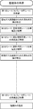
- the method for manufacturing a stacked SOFC of the present invention includes a step of preparing a stacked body that is a precursor of a stack structure, and a step of heat-treating the stacked body.
- FIG. 5 shows an example of this manufacturing process.
- the laminate preparation step includes preparing a first sheet including a solid electrolyte material that is a material of a solid electrolyte or a separator material that is a material of a separator, an electrode material band including a fuel electrode material or an air electrode material, and at least thermal expansion Preparing a second sheet having a sealing material band for forming a non-porous seal portion equivalent to the solid electrolyte or the separator with respect to shrinkage properties, and laminating on the first sheet It is the process of repeating and preparing a laminated body.
- the laminated body is a precursor of a stack structure body, it means what was laminated
- a vanishing material layer for forming an air gas circulation part is formed on a first sheet containing a separator material, and then an electrode material band made of an air electrode material and a solid electrolyte material.
- a second sheet having a sealing material band is laminated.
- seat containing a separator material can be obtained by making the separator material already demonstrated into a sheet according to a conventional method.
- the first sheet and the second sheet are both unfired ceramic sheets that become the intended ceramics by heat treatment after lamination.
- Such a first sheet is, for example, a tape casting method using a coating material such as a knife coater or a doctor blade with a slurry containing a separator material as a main component and an appropriate amount of a binder resin, an organic solvent, and the like. It can be obtained using a sheet forming method by casting.
- a first sheet (unfired ceramic green sheet) can be obtained by drying the obtained sheet according to a conventional method, followed by heat treatment as necessary.
- the separator material is preferably a ceramic powder containing a lanthanum-chromium perovskite oxide and a rare earth element solid solution zirconia.
- the rare earth element-stabilized zirconia the lanthanum-chromium perovskite oxide can be densely sintered even at a firing temperature of about 1400 ° C. or less, and co-sintering with the cell constituent elements becomes possible. Also, high conductivity can be maintained.
- the rare earth solid solution zirconia is preferably 0.05% by mass or more and 10% by mass or less based on the mass of the lanthanum-chromium perovskite oxide ceramics. This is because if it is less than 0.05% by mass, the effect of lowering the sintering temperature is not sufficiently obtained, and even if it exceeds 10% by mass, the conductivity may decrease.
- the second sheet includes a sealing material band made of an air electrode material band and a solid electrolyte material.
- the arrangement of the air electrode material band and the seal material band can be determined based on the design concept of the seal portion already described for the stacked SOFC of the present invention.
- zone (band) can be obtained by sheet forming methods by casting, such as a tape casting method, using coating apparatuses, such as a doctor blade. That is, the slurry having different compositions along the casting direction is discharged at the same time, and the different slurry zones are integrated without being mixed after casting. At this time, such different composition band can be integrally applied by adjusting the fluidity of the slurry for forming different bands.
- the coated material obtained in this way can be dried according to a conventional method, and heat-treated as necessary to obtain a second sheet.
- the slurry for the air electrode material strip can be obtained by slurrying the air electrode material already described according to a conventional method.
- a foaming material etc. can be added to the slurry for air electrode material strips as needed.
- a solid slurry can be used to form a suitable slurry, which can be used for coating.
- the second sheet is laminated on the first sheet prepared in this way.
- the direction of the second sheet relative to the first sheet is such that the anode material band and the seal material band are arranged so as to have an intended stack structure.
- the second material layer is applied after the disappearance material layer is applied by predetermined patterning to form the gas flow part.
- These sheets are preferably laminated.
- first sheet made of a solid electrolyte material
- second sheet having a fuel electrode material body and a seal material band
- the solid electrolyte material and the fuel electrode material slurry may be used by slurrying the above-described solid electrolyte and fuel electrode materials, respectively.
- a foaming agent or the like can be included as necessary in order to ensure the porosity after the heat treatment.
- the types of the first sheet and the second sheet to be laminated are determined according to the stack structure (the structure in which the single cell is separated by the separator) to be finally obtained. The same applies to the directionality of each sheet during lamination.
- the stacking order in the stacking step can be arbitrarily performed as long as the stack structure can be obtained, and is not particularly limited.
- the lamination of the first sheet and the second sheet may be sequentially performed, or these laminated bodies may be laminated after a partial laminated body is produced.
- the various aspects already described in the stack structure of the present invention can be applied to the selection and arrangement of the composition of the sealing material band in the second sheet.
- Various aspects described in the stack structure of the present invention described above can also be applied to the gas circulation part.
- the heat treatment step is a step of heat-treating the laminate as a precursor of the stack structure obtained in the lamination step.
- the heat treatment is carried out so that at least a part of the ceramic material constituting the laminate is sintered to obtain a desired dense or porous fired body.
- all of the cell components and separator are co-sintered.
- the heat treatment can be performed at a temperature of 1250 ° C. to 1550 ° C., and preferably 1300 ° C. to 1500 ° C. More preferably, it is 1300 degreeC or more and 1400 degrees C or less. It can be fired in air.
- the sheets constituting the laminate are integrated by this heat treatment, and the stack structure of the present invention can be obtained. That is, the single cell is separated by the separator, and a stack structure body in which a portion functioning as a seal portion is integrated in advance in the fuel electrode layer or the air electrode layer of the single cell can be obtained at a time. .
- the stack structure can be formed all at once. Obtainable. That is, the stack structure of the present invention having various advantages can be easily obtained.
- the electrode sheet for a stacked SOFC of the present invention has an electrode material band containing a fuel electrode material or an air electrode material, and a seal material band for forming a non-porous seal portion in the stacked SOFC.
- the seal portion can be formed in the fuel electrode layer or the air electrode layer, and thus a reliable and simple seal structure can be provided.
- a stack structure that has a good integrity with an adjacent separator or solid electrolyte and is excellent in mechanical strength by making the sealing material band at least uniform with the solid electrolyte or separator of the stacked SOFC at least in terms of thermal expansion and contraction characteristics. Can be obtained.
- the electrode sheet of the present invention various aspects can be applied to the fuel electrode, air electrode, separator, solid electrolyte, and seal portion already described in the stack structure of the present invention. Moreover, the manufacturing method of the 2nd sheet
- 8YSZ 8YSZ as an electrolyte
- La 0.79 Ca 0.06 Sr 0.15 CrO x (LCaSCr) was used, and each of these slurries was prepared, and a separator sheet and a solid electrolyte sheet were formed into a green sheet having a thickness of 20 ⁇ m to 80 ⁇ m by a tape casting method.
- a 20 ⁇ m-thick green sheet having an air electrode material band and a sealing material band made of a separator material on one end side of the air electrode material band was prepared.
- a green sheet having a thickness of 20 ⁇ m and having a sealing material band was produced. In order to equalize the shrinkage of the green sheet happens to come, the slurry concentration was adjusted for each sheet.
- each of the fuel electrode layer, the air electrode layer, and the solid electrolyte was about 15 ⁇ m.
- the composition of the cross section was confirmed using energy dispersive spectroscopy (EDX).
- EDX energy dispersive spectroscopy
- Example 2 when laminating the separator sheet and the air electrode sheet and the separator sheet and the fuel electrode sheet in Example 1, the carbon paste was screen-printed and fired in the same manner as in Example 1. As a result, it was found that the structure obtained had voids formed in the carbon paste coating region while maintaining the integrity of the entire structure. From the above, it was found that a fine gas flow path can be formed using the disappearing material.
- LCaSCr powder 1% by mass, 2% by mass, 3% by mass, 4% by mass, 5% by mass, and 7% by mass of 3YSZ (3 mol% yttria) with respect to the mass of the oxide powder.
- Stabilized zirconia and about 10% by mass of calcium nitrate were added to the oxide powder and mixed well in a mortar.
- the mixed powder was molded by a uniaxial press (1300 kgf / cm 2 , 5 minutes) and then fired at 1300 ° C. for 5 hours in the air.
- 3YSZ except having not added 3YSZ, the same operation was performed and the comparative example was also produced (calcium nitrate containing 3YSZ "0" mass% sample).
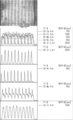
- the volume and weight of the obtained sintered body were determined, and the density was calculated. The results are shown in FIG. Moreover, the result (0 mass% and 1 mass% addition) which observed the cross section of the obtained sintered compact with the scanning electron microscope (SEM) is shown in FIG.
- the density of the lanthanum-calcium-strontium-chromium oxide which was 5.3 g / cm 3 when 3YSZ was not added, was 6% when 3YSZ was added with only 1% by mass, and 5% by mass. It was found that the addition increased 9%. Further, as shown in FIG. 9, it was confirmed by scanning electron microscope (SEM) observation that the crystal grains were refined and dense by adding a small amount of 3YSZ.
Landscapes
- Chemical & Material Sciences (AREA)
- Life Sciences & Earth Sciences (AREA)
- Engineering & Computer Science (AREA)
- Manufacturing & Machinery (AREA)
- Sustainable Development (AREA)
- Sustainable Energy (AREA)
- Chemical Kinetics & Catalysis (AREA)
- Electrochemistry (AREA)
- General Chemical & Material Sciences (AREA)
- Inorganic Chemistry (AREA)
- Fuel Cell (AREA)
- Inert Electrodes (AREA)
Abstract
Description
(a)固体電解質の材料である固体電解質材料又はセパレータの材料であるセパレータ材料を含む第1のシートを準備する工程、(b)燃料極材料又は空気極材料を含む電極材料帯と、少なくとも熱膨張収縮特性に関して前記固体電解質又は前記セパレータと均等な非多孔質部材料を形成するための非多孔質材料帯と、を有する第2のシートを準備し前記第1のシート上に積層する工程、を繰り返し実施して積層体を準備する工程と、前記積層体を熱処理する工程と、を備える、積層型固体酸化物形燃料電池の製造方法が提供される。
本発明のスタック構造体は、各種形態を採ることができるが、以下、図1~図3を参照して、本発明のスタック構造体について説明する。
燃料極層6は、燃料極7とともにシール部10aを備える。燃料極層6は、燃料極層6の厚みの範囲内においてシール部10aを有している。好ましくは、燃料極層6の厚みに一致する程度のシール部10aを有している。シール部10aは、燃料極7の周縁部に一体化されて、全体として燃料極層6を構成している。シール部10aは、少なくとも空気ガス及び燃料ガスに対して、SOFCにおいて要求される程度の気密性を発揮できる程度の非多孔質に形成されており、燃料極層6の燃料極7がその対極である空気極9に供給される空気ガスへ暴露されるのを回避し、燃料ガス及び空気ガスのそれぞれ独立した流通形態を確保できるように形成されている。したがって、燃料極7の周縁部のいずれの箇所に形成されるかは、燃料ガス流通部16や空気ガス流通部18のパターン及びこれらの二つの供給部16、18のスタック構造体20における配置形態に依存している。より具体的には、シール部10aは、空気ガスの供給部18の開口19の開放側となる周縁部に形成されて空気ガスへの燃料極7の暴露を防止している。
空気極層8は、空気極9とともにシール部10bを備える。シール部10bは、空気極層8の厚みの範囲内においてシール部10bを有している。好ましくは、空気極8の厚みに一致する程度のシール部10bを有している。シール部10bは、シール部10aと同様に、空気極9の周縁部に一体化されて、全体として空気極層8を構成している。シール部10bは、空気極9が燃料ガスに暴露されるのを回避し、燃料ガス及び空気ガスのそれぞれ独立した流通形態を確保できるように形成されている。なお、シール部10bは、シール部10aが、燃料極9の空気ガスへの暴露を防止するものであるのに対してシール部10bが空気極9の燃料ガスへの暴露を防止する点以外は、シール部10aと同様の構成を採ることができる。すなわち、既に説明したシール部10aの非多孔質性、空気極層8及び熱膨張係数に関しての各種態様をそのまま適用できる。
図1に示すように、スタック構造体20の単セル2は、燃料極7に燃料ガスを供給する燃料ガス流通部16及び空気極9に空気ガスを供給する空気ガス流通部18を備えている。これらのガス流通部16、18のパターンや形態は特に限定されない。例えば、図1に示すコの字状、図2に示すストレート型のほか、ジグザグ状、放射状、螺旋状等各種パターンが挙げられる。その他、SOFCにおけるこれらガス流通部については公知の態様を適用できる。これらの供給部16,18は、中空状の流路であることが好ましく、より好ましくは、セパレータ14側に形成されている。本発明のスタック構造体20においては、図1に示すように、これらガス流通部16、18は、コの字状の流路パターンを有し、その開口17、19をスタック構造体20の対向する面においてのみ開放される形態が好ましい。こうした形態であると、燃料極層6及び空気極層8においてシール部10a及び10bをそれぞれ回避すべきガス流通部の開口の開放面においてのみ形成すれば足りるからである。
本発明の積層型SOFCは、本発明のスタック構造体を備えることができる。本発明のスタック構造体に対して、適宜必要な部材、すなわち、スタック構造体への燃料ガス及び空気ガスの供給源からのガス供給系、集電部材やケーシング等を備えることで積層型SOFCを構築できる。
本発明のSOFCシステムは、本発明の積層型SOFCを備えることができる。積層型SOFCは、単体であってもよいが、通常、意図した電力を出力するように、積層型SOFCを複数組み合わせたモジュールを1個又は複数個を備えている。SOFCシステムは、さらに、燃料ガス改質装置、熱交換器及びタービン等、公知のSOFCシステムの要素を備えることができる。
本発明の積層型SOFCの製造方法は、図4に示すように、スタック構造体の前駆体である積層体を準備する工程と、この積層体を熱処理する工程と、を備えている。図5には、この製造工程の一例を記載している。
積層体準備工程は、固体電解質の材料である固体電解質材料又はセパレータの材料であるセパレータ材料を含む第1のシートを準備し、燃料極材料又は空気極材料を含む電極材料帯と、少なくとも熱膨張収縮特性に関して前記固体電解質又は前記セパレータと均等な非多孔質性のシール部を形成するためのシール材料帯と、を有する第2のシートを準備して、第1のシート上に積層することを繰り返して、積層体を準備する工程である。なお、ここでいう積層体は、スタック構造体の前駆体であるので、単セルがセパレータにより分離された状態で積層されたものをいう。
熱処理工程は、積層工程で得られたスタック構造体の前駆体としての積層体を熱処理する工程である。熱処理は、積層体を構成するセラミックス材料が少なくとも一部が焼結されて緻密質又は多孔質の所望の焼成体を得られるように実施する。好ましくは、セル構成要素及びセパレータの全てを共焼結させる。例えば、1250℃以上1550℃以下の温度で加熱処理することができ、好ましくは1300℃以上1500℃以下である。より好ましくは1300℃以上1400℃以下である。なお、空気中で焼成することができる。
本発明の積層型SOFC用電極シートは、燃料極材料又は空気極材料を含む電極材料帯と、前記積層型SOFCにおいて非多孔質性のシール部を形成するためのシール材料帯と、を有することができる。本発明のシートによれば、燃料極層又は空気極層の層内においてシール部を形成することができ、このため、確実かつ簡易なシール構造を提供できる。特に、シール材料帯を、少なくとも熱膨張収縮特性に関して積層型SOFCの固体電解質又はセパレータと均等とすることで、隣接するセパレータ又は固体電解質との一体性が良好で機械的強度にも優れるスタック構造体を得ることができる。
Claims (15)
- 固体電解質を挟んで対向状に配置される燃料極を含む燃料極層と空気極を含む空気極層とを含んで積層される複数個の単セルと、
積層される前記単セル間に介在されて前記単セル間を分離するセパレータと、
前記燃料極層及び前記空気極層の各層内にあって、少なくとも熱膨張収縮特性に関して前記セパレータ又は前記固体電解質と均等であって前記燃料極の周縁部又は前記空気極の周縁部に一体化されるとともに隣接する前記セパレータ及び前記固体電解質に一体化される非多孔質性のシール部と、
を備え、
前記燃料極及び前記空気極にそれぞれ供給される燃料ガス及び空気ガスを分離させて流通可能に形成されている、固体酸化物形燃料電池用スタック構造体。 - 前記単セルは、前記固体電解質、前記燃料極層及び前記空気極層の厚みは、それぞれ1μm以上150μm以下である、請求項1に記載のスタック構造体。
- 前記単セル内部に機械的強度を高めた単セル支持部を備えていない請求項1又は2に記載のスタック構造体。
- 前記シール部は、前記セパレータ又は前記固体電解質と同一組成を有する、請求項1~3のいずれかに記載のスタック構造体。
- 前記シール部は、前記燃料極層又は前記空気極層に及ぶ前記セパレータ又は前記固体電解質の一部を含む、請求項1~4のいずれかに記載のスタック構造体。
- 前記単セルとこれに組み合わされる1個又は2個の前記セパレータとからなるユニットは、全体として平板状である、請求項1~5のいずれかに記載のスタック構造体。
- 前記セパレータは、ランタン-クロム系ペロブスカイト型酸化物と希土類元素を固溶させたジルコニアとを含む、請求項1~6のいずれかに記載のスタック構造体。
- 請求項1~7のいずれかに記載の固体酸化物形燃料電池用のスタック構造体を備える、固体酸化物形燃料電池。
- 請求項1~7のいずれかに記載の固体酸化物形燃料電池用のスタック構造体を備える、固体酸化物形燃料電池システム。
- 固体電解質を挟んで対向状に配置される燃料極を含む燃料極層と空気極を含む空気極層ととを含む単セルと積層される当該単セル間をセパレータで分離する積層型固体酸化物形燃料電池の製造方法であって、
以下の(a)及び(b);
(a)固体電解質の材料である固体電解質材料又はセパレータの材料であるセパレータ材料を含む第1のシートを準備する工程、
(b)燃料極材料又は空気極材料を含む電極材料帯と、少なくとも熱膨張収縮特性に関して前記固体電解質又は前記セパレータと均等な非多孔質性のシール部を形成するためのシール材料帯と、を有する第2のシートを準備し前記第1のシート上に積層する工程、
を繰り返し実施して積層体を準備する工程と、
前記積層体を熱処理する工程と、
を備える、積層型固体酸化物形燃料電池の製造方法。 - 前記第2のシートの前記シール材料帯は前記第1のシートと同一組成を有する、請求項10に記載の積層型固体酸化物形燃料電池の製造方法。
- 前記第2のシートを、テープキャスト法で作製する、請求項10又は11に記載の積層型固体酸化物形燃料電池の製造方法。
- 前記第2のシートを、前記電極材料帯と前記非多孔質材料帯とを同時にキャスティングすることによって作製する、請求項12に記載の積層型固体酸化物形燃料電池の製造方法。
- さらに、前記(a)工程後前記(b)工程に先立って、燃料ガス又は空気ガスの流通部のパターンを有し前記第1のシート上に前記熱処理によって消失される消失材料からなる消失材料層を付与する、請求項10~13のいずれかに記載の積層型固体酸化物形燃料電池の製造方法。
- 前記セパレータ材料は、ランタン-クロム系ペロブスカイト型酸化物と希土類元素を固溶させたジルコニアとを含む、請求項10~14のいずれかに記載の積層型固体酸化物形燃料電池の製造方法。
Priority Applications (8)
| Application Number | Priority Date | Filing Date | Title |
|---|---|---|---|
| CA2723238A CA2723238C (en) | 2008-03-26 | 2009-03-26 | Stack structure for laminated solid oxide fuel cell, laminated solid oxide fuel cell and manufacturing method |
| ES09725111.0T ES2502525T3 (es) | 2008-03-26 | 2009-03-26 | Estructura de apilamiento para el apilamiento de pilas de combustible de óxido sólido, el apilamiento de pilas de combustible de óxido sólido y método de producción de la misma |
| US12/934,471 US8658328B2 (en) | 2008-03-26 | 2009-03-26 | Stack structure for laminated solid oxide fuel cell, laminated solid oxide fuel cell and manufacturing method |
| DK09725111.0T DK2273598T3 (en) | 2008-03-26 | 2009-03-26 | Stack structure for a solid oxide fuel cell stack, solid oxide fuel cell stack, and method for making the same |
| KR1020107023238A KR101694134B1 (ko) | 2008-03-26 | 2009-03-26 | 적층형 고체 산화물형 연료 전지용 스택 구조체, 적층형 고체 산화물형 연료 전지 및 그 제조 방법 |
| CN2009801107573A CN102099954B (zh) | 2008-03-26 | 2009-03-26 | 层叠型固体氧化物燃料电池用的堆结构体、层叠型固体氧化物燃料电池及其制造方法 |
| JP2010505799A JP4950334B2 (ja) | 2008-03-26 | 2009-03-26 | 積層型固体酸化物形燃料電池用スタック構造体、積層型固体酸化物形燃料電池及びその製造方法 |
| EP09725111.0A EP2273598B1 (en) | 2008-03-26 | 2009-03-26 | Stack structure for solid oxide fuel cell stack, solid oxide fuel cell stack, and production method for the same |
Applications Claiming Priority (2)
| Application Number | Priority Date | Filing Date | Title |
|---|---|---|---|
| JP2008-080794 | 2008-03-26 | ||
| JP2008080794 | 2008-03-26 |
Publications (1)
| Publication Number | Publication Date |
|---|---|
| WO2009119771A1 true WO2009119771A1 (ja) | 2009-10-01 |
Family
ID=41113958
Family Applications (1)
| Application Number | Title | Priority Date | Filing Date |
|---|---|---|---|
| PCT/JP2009/056188 WO2009119771A1 (ja) | 2008-03-26 | 2009-03-26 | 積層型固体酸化物形燃料電池用スタック構造体、積層型固体酸化物形燃料電池及びその製造方法 |
Country Status (9)
| Country | Link |
|---|---|
| US (1) | US8658328B2 (ja) |
| EP (1) | EP2273598B1 (ja) |
| JP (4) | JP4950334B2 (ja) |
| KR (1) | KR101694134B1 (ja) |
| CN (2) | CN103647100A (ja) |
| CA (1) | CA2723238C (ja) |
| DK (1) | DK2273598T3 (ja) |
| ES (1) | ES2502525T3 (ja) |
| WO (1) | WO2009119771A1 (ja) |
Cited By (8)
| Publication number | Priority date | Publication date | Assignee | Title |
|---|---|---|---|---|
| JP2012003893A (ja) * | 2010-06-15 | 2012-01-05 | Ngk Spark Plug Co Ltd | 固体酸化物形燃料電池及びその製造方法 |
| JP2014501437A (ja) * | 2010-12-28 | 2014-01-20 | ポスコ | 固体酸化物燃料電池とその製造方法および燃料極製造のためのテープキャスティング装置 |
| WO2014122807A1 (ja) * | 2013-02-07 | 2014-08-14 | FCO Power株式会社 | 固体酸化物形燃料電池及びその製造方法 |
| WO2015025642A1 (ja) * | 2013-08-21 | 2015-02-26 | 株式会社村田製作所 | 電気化学素子用セラミック基体及びその製造方法並びに燃料電池及び燃料電池スタック |
| WO2015056320A1 (ja) * | 2013-10-17 | 2015-04-23 | FCO Power株式会社 | 固体酸化物形燃料電池スタックアレイ |
| WO2017154258A1 (ja) * | 2016-03-11 | 2017-09-14 | 日産自動車株式会社 | 燃料電池スタックの製造方法 |
| WO2018042475A1 (ja) * | 2016-08-29 | 2018-03-08 | FCO Power株式会社 | 固体酸化物形燃料電池用セル、固体酸化物形燃料電池スタック及び固体酸化物形燃料電池 |
| WO2023191464A1 (ko) * | 2022-03-31 | 2023-10-05 | 주식회사 에이엠엑스랩 | 박막형 고체산화물 연료전지 패키지 |
Families Citing this family (32)
| Publication number | Priority date | Publication date | Assignee | Title |
|---|---|---|---|---|
| CN103647100A (zh) * | 2008-03-26 | 2014-03-19 | 财团法人日本精细陶瓷中心 | 层叠型固体氧化物燃料电池用的堆结构体、层叠型固体氧化物燃料电池及其制造方法 |
| KR101381658B1 (ko) | 2008-12-18 | 2014-04-08 | 생-고뱅 세라믹스 앤드 플라스틱스, 인코포레이티드 | 도핑을 통한 고소결성 란타넘 스트론튬 티타네이트 연결재 |
| US9561476B2 (en) | 2010-12-15 | 2017-02-07 | Praxair Technology, Inc. | Catalyst containing oxygen transport membrane |
| US9486735B2 (en) | 2011-12-15 | 2016-11-08 | Praxair Technology, Inc. | Composite oxygen transport membrane |
| CN103987681B (zh) | 2011-12-15 | 2016-08-24 | 普莱克斯技术有限公司 | 复合氧气传送膜 |
| US9406963B2 (en) | 2011-12-22 | 2016-08-02 | Saint-Gobain Ceramics & Plastics, Inc. | Solid oxide fuel cell interconnects including a ceramic interconnect material and partially stabilized zirconia |
| JP2014007127A (ja) * | 2012-06-27 | 2014-01-16 | Nippon Telegr & Teleph Corp <Ntt> | 固体酸化物形燃料電池用単セルの製造方法、固体酸化物形燃料電池用単セルおよび固体酸化物形燃料電池 |
| CN104396070B (zh) * | 2012-07-02 | 2016-03-02 | 日产自动车株式会社 | 燃料电池堆 |
| US9969645B2 (en) | 2012-12-19 | 2018-05-15 | Praxair Technology, Inc. | Method for sealing an oxygen transport membrane assembly |
| US9453644B2 (en) | 2012-12-28 | 2016-09-27 | Praxair Technology, Inc. | Oxygen transport membrane based advanced power cycle with low pressure synthesis gas slip stream |
| US9296671B2 (en) | 2013-04-26 | 2016-03-29 | Praxair Technology, Inc. | Method and system for producing methanol using an integrated oxygen transport membrane based reforming system |
| US9611144B2 (en) | 2013-04-26 | 2017-04-04 | Praxair Technology, Inc. | Method and system for producing a synthesis gas in an oxygen transport membrane based reforming system that is free of metal dusting corrosion |
| US9212113B2 (en) | 2013-04-26 | 2015-12-15 | Praxair Technology, Inc. | Method and system for producing a synthesis gas using an oxygen transport membrane based reforming system with secondary reforming and auxiliary heat source |
| US9938145B2 (en) | 2013-04-26 | 2018-04-10 | Praxair Technology, Inc. | Method and system for adjusting synthesis gas module in an oxygen transport membrane based reforming system |
| WO2015054228A2 (en) | 2013-10-07 | 2015-04-16 | Praxair Technology, Inc. | Ceramic oxygen transport membrane array reactor and reforming method |
| BR112016007641B1 (pt) | 2013-10-08 | 2021-05-04 | Praxair Technology, Inc | método para controle de temperatura em um reator, e, reator |
| WO2015084729A1 (en) | 2013-12-02 | 2015-06-11 | Praxair Technology, Inc. | Method and system for producing hydrogen using an oxygen transport membrane based reforming system with secondary reforming |
| CN105980666B (zh) | 2014-02-12 | 2019-04-09 | 普莱克斯技术有限公司 | 用于生成电力的基于氧传输膜反应器的方法和系统 |
| US10822234B2 (en) | 2014-04-16 | 2020-11-03 | Praxair Technology, Inc. | Method and system for oxygen transport membrane enhanced integrated gasifier combined cycle (IGCC) |
| US9789445B2 (en) | 2014-10-07 | 2017-10-17 | Praxair Technology, Inc. | Composite oxygen ion transport membrane |
| CN107431215B (zh) * | 2015-03-26 | 2020-10-16 | 森村索福克科技股份有限公司 | 电化学反应单元和燃料电池堆 |
| US10441922B2 (en) | 2015-06-29 | 2019-10-15 | Praxair Technology, Inc. | Dual function composite oxygen transport membrane |
| US10118823B2 (en) | 2015-12-15 | 2018-11-06 | Praxair Technology, Inc. | Method of thermally-stabilizing an oxygen transport membrane-based reforming system |
| US9938146B2 (en) | 2015-12-28 | 2018-04-10 | Praxair Technology, Inc. | High aspect ratio catalytic reactor and catalyst inserts therefor |
| CN109070014A (zh) | 2016-04-01 | 2018-12-21 | 普莱克斯技术有限公司 | 含催化剂的氧气传送膜 |
| WO2019012666A1 (ja) * | 2017-07-13 | 2019-01-17 | FCO Power株式会社 | 固体酸化物形燃料電池の空気極用材料及びその利用 |
| EP3667788B1 (en) | 2017-08-10 | 2024-05-01 | Nissan Motor Co., Ltd. | Cell structure for fuel cell and fuel cell system |
| CN108336386B (zh) * | 2017-12-28 | 2020-04-17 | 浙江臻泰能源科技有限公司 | 扁管结构固体氧化物电化学器件及其制备方法 |
| US11136238B2 (en) | 2018-05-21 | 2021-10-05 | Praxair Technology, Inc. | OTM syngas panel with gas heated reformer |
| JP7245036B2 (ja) * | 2018-11-28 | 2023-03-23 | 太陽誘電株式会社 | 燃料電池スタックおよびその製造方法 |
| JP7330689B2 (ja) * | 2018-11-28 | 2023-08-22 | 太陽誘電株式会社 | 燃料電池および燃料電池スタック |
| US20230006233A1 (en) * | 2019-11-08 | 2023-01-05 | Hitachi High-Tech Corporation | Fuel Cell and Method for Producing Fuel Cell |
Citations (7)
| Publication number | Priority date | Publication date | Assignee | Title |
|---|---|---|---|---|
| JPS58129766A (ja) * | 1982-01-29 | 1983-08-02 | Hitachi Ltd | 溶融塩型燃料電池 |
| JPH0745295A (ja) * | 1993-07-30 | 1995-02-14 | Sanyo Electric Co Ltd | 固体電解質燃料電池用ガスシール材 |
| JP2003297387A (ja) * | 2002-03-29 | 2003-10-17 | Tdk Corp | 固体電解質燃料電池の製造方法および固体電解質燃料電池 |
| JP2003346842A (ja) | 2002-05-23 | 2003-12-05 | Nissan Motor Co Ltd | 固体酸化物型燃料電池用セル板及びその製造方法 |
| JP2005085522A (ja) | 2003-09-05 | 2005-03-31 | Mitsubishi Materials Corp | 支持膜式固体酸化物形燃料電池 |
| JP2007273429A (ja) * | 2006-03-31 | 2007-10-18 | Dainippon Printing Co Ltd | 固体酸化物形燃料電池、及びその製造方法 |
| JP2008034373A (ja) * | 2006-06-28 | 2008-02-14 | Ngk Insulators Ltd | 固体酸化物形燃料電池、その冷却方法、及び固体酸化物形燃料電池システム |
Family Cites Families (22)
| Publication number | Priority date | Publication date | Assignee | Title |
|---|---|---|---|---|
| JPH01151161A (ja) * | 1987-12-08 | 1989-06-13 | Mitsubishi Electric Corp | 燃料電池 |
| JP2980921B2 (ja) * | 1989-08-29 | 1999-11-22 | 東燃株式会社 | 平板型固体電解質燃料電池 |
| JPH04149966A (ja) * | 1990-10-15 | 1992-05-22 | Ishikawajima Harima Heavy Ind Co Ltd | 固体電解質型燃料電池 |
| JPH05182678A (ja) * | 1992-01-08 | 1993-07-23 | Sanyo Electric Co Ltd | 固体電解質型燃料電池 |
| JP3170868B2 (ja) * | 1992-05-28 | 2001-05-28 | 株式会社村田製作所 | 固体電解質型燃料電池 |
| JP3448876B2 (ja) * | 1992-05-28 | 2003-09-22 | 株式会社村田製作所 | 固体電解質型燃料電池 |
| US5589285A (en) * | 1993-09-09 | 1996-12-31 | Technology Management, Inc. | Electrochemical apparatus and process |
| JPH08124591A (ja) * | 1994-08-29 | 1996-05-17 | Murata Mfg Co Ltd | 固体電解質型燃料電池の製造方法 |
| JPH07245115A (ja) * | 1994-03-03 | 1995-09-19 | Murata Mfg Co Ltd | 固体電解質型燃料電池 |
| JP3791702B2 (ja) * | 1995-09-12 | 2006-06-28 | 財団法人石油産業活性化センター | 平板状固体電解質燃料電池 |
| EP1199760B1 (en) * | 1999-05-31 | 2010-04-21 | Central Research Institute of Electric Power Industry | Unit cell of flat solid electrolytic fuel battery and cell stack comprising the same |
| US6264807B1 (en) * | 1999-11-08 | 2001-07-24 | The United States Of America As Represented By The Secretary Of The Air Force | Ceramic oxygen generation system |
| US6811913B2 (en) * | 2000-11-15 | 2004-11-02 | Technology Management, Inc. | Multipurpose reversible electrochemical system |
| US7279241B2 (en) * | 2004-06-30 | 2007-10-09 | Corning Incorporated | Electrolyte sheet with a corrugation pattern |
| CA2627786C (en) | 2004-11-30 | 2012-03-27 | The Regents Of The University Of California | Braze system with matched coefficients of thermal expansion |
| US7534519B2 (en) * | 2005-09-16 | 2009-05-19 | The United States Of America As Represented By The Administrator Of The National Aeronautics And Space Administration | Symmetrical, bi-electrode supported solid oxide fuel cell |
| CA2623302A1 (en) | 2005-09-20 | 2007-03-29 | Kyocera Corporation | Fuel cell and method for manufacturing the same |
| JP5005947B2 (ja) | 2006-04-19 | 2012-08-22 | 日本電信電話株式会社 | 固体酸化物形燃料電池のガスシール構造 |
| WO2008013498A1 (en) * | 2006-07-26 | 2008-01-31 | Sandvik Intellectual Property Ab | Ferritic chromium steel |
| US7754367B2 (en) * | 2007-06-28 | 2010-07-13 | Delphi Technologies, Inc. | Solid bonded interconnect system in a lightweight solid oxide fuel cell stack |
| CN103647100A (zh) * | 2008-03-26 | 2014-03-19 | 财团法人日本精细陶瓷中心 | 层叠型固体氧化物燃料电池用的堆结构体、层叠型固体氧化物燃料电池及其制造方法 |
| US20090286125A1 (en) * | 2008-04-03 | 2009-11-19 | The University Of Toledo | Bi-electrode supported solid oxide fuel cells having gas flow plenum channels and methods of making same |
-
2009
- 2009-03-26 CN CN201310495422.6A patent/CN103647100A/zh active Pending
- 2009-03-26 WO PCT/JP2009/056188 patent/WO2009119771A1/ja active Application Filing
- 2009-03-26 JP JP2010505799A patent/JP4950334B2/ja not_active Expired - Fee Related
- 2009-03-26 US US12/934,471 patent/US8658328B2/en not_active Expired - Fee Related
- 2009-03-26 KR KR1020107023238A patent/KR101694134B1/ko active IP Right Grant
- 2009-03-26 DK DK09725111.0T patent/DK2273598T3/en active
- 2009-03-26 ES ES09725111.0T patent/ES2502525T3/es active Active
- 2009-03-26 EP EP09725111.0A patent/EP2273598B1/en active Active
- 2009-03-26 CN CN2009801107573A patent/CN102099954B/zh active Active
- 2009-03-26 CA CA2723238A patent/CA2723238C/en not_active Expired - Fee Related
-
2011
- 2011-12-15 JP JP2011275058A patent/JP4950358B2/ja not_active Expired - Fee Related
- 2011-12-21 JP JP2011279668A patent/JP5390587B2/ja active Active
-
2013
- 2013-10-10 JP JP2013213075A patent/JP5767297B2/ja not_active Expired - Fee Related
Patent Citations (7)
| Publication number | Priority date | Publication date | Assignee | Title |
|---|---|---|---|---|
| JPS58129766A (ja) * | 1982-01-29 | 1983-08-02 | Hitachi Ltd | 溶融塩型燃料電池 |
| JPH0745295A (ja) * | 1993-07-30 | 1995-02-14 | Sanyo Electric Co Ltd | 固体電解質燃料電池用ガスシール材 |
| JP2003297387A (ja) * | 2002-03-29 | 2003-10-17 | Tdk Corp | 固体電解質燃料電池の製造方法および固体電解質燃料電池 |
| JP2003346842A (ja) | 2002-05-23 | 2003-12-05 | Nissan Motor Co Ltd | 固体酸化物型燃料電池用セル板及びその製造方法 |
| JP2005085522A (ja) | 2003-09-05 | 2005-03-31 | Mitsubishi Materials Corp | 支持膜式固体酸化物形燃料電池 |
| JP2007273429A (ja) * | 2006-03-31 | 2007-10-18 | Dainippon Printing Co Ltd | 固体酸化物形燃料電池、及びその製造方法 |
| JP2008034373A (ja) * | 2006-06-28 | 2008-02-14 | Ngk Insulators Ltd | 固体酸化物形燃料電池、その冷却方法、及び固体酸化物形燃料電池システム |
Non-Patent Citations (1)
| Title |
|---|
| See also references of EP2273598A4 |
Cited By (13)
| Publication number | Priority date | Publication date | Assignee | Title |
|---|---|---|---|---|
| JP2012003893A (ja) * | 2010-06-15 | 2012-01-05 | Ngk Spark Plug Co Ltd | 固体酸化物形燃料電池及びその製造方法 |
| JP2014501437A (ja) * | 2010-12-28 | 2014-01-20 | ポスコ | 固体酸化物燃料電池とその製造方法および燃料極製造のためのテープキャスティング装置 |
| WO2014122807A1 (ja) * | 2013-02-07 | 2014-08-14 | FCO Power株式会社 | 固体酸化物形燃料電池及びその製造方法 |
| JPWO2014122807A1 (ja) * | 2013-02-07 | 2017-01-26 | FCO Power株式会社 | 固体酸化物形燃料電池及びその製造方法 |
| WO2015025642A1 (ja) * | 2013-08-21 | 2015-02-26 | 株式会社村田製作所 | 電気化学素子用セラミック基体及びその製造方法並びに燃料電池及び燃料電池スタック |
| US9722259B2 (en) | 2013-08-21 | 2017-08-01 | Murata Manufacturing Co., Ltd. | Ceramic substrate for electrochemical element, manufacturing method therefore, fuel cell, and fuel cell stack |
| JPWO2015056320A1 (ja) * | 2013-10-17 | 2017-03-09 | FCO Power株式会社 | 固体酸化物形燃料電池スタックアレイ |
| WO2015056320A1 (ja) * | 2013-10-17 | 2015-04-23 | FCO Power株式会社 | 固体酸化物形燃料電池スタックアレイ |
| WO2017154258A1 (ja) * | 2016-03-11 | 2017-09-14 | 日産自動車株式会社 | 燃料電池スタックの製造方法 |
| US10693154B2 (en) | 2016-03-11 | 2020-06-23 | Nissan Motor Co., Ltd. | Method for manufacturing fuel cell stack |
| WO2018042475A1 (ja) * | 2016-08-29 | 2018-03-08 | FCO Power株式会社 | 固体酸化物形燃料電池用セル、固体酸化物形燃料電池スタック及び固体酸化物形燃料電池 |
| JPWO2018042475A1 (ja) * | 2016-08-29 | 2018-08-30 | FCO Power株式会社 | 固体酸化物形燃料電池用セル、固体酸化物形燃料電池スタック及び固体酸化物形燃料電池 |
| WO2023191464A1 (ko) * | 2022-03-31 | 2023-10-05 | 주식회사 에이엠엑스랩 | 박막형 고체산화물 연료전지 패키지 |
Also Published As
| Publication number | Publication date |
|---|---|
| ES2502525T3 (es) | 2014-10-03 |
| JPWO2009119771A1 (ja) | 2011-07-28 |
| JP5767297B2 (ja) | 2015-08-19 |
| EP2273598A1 (en) | 2011-01-12 |
| JP4950334B2 (ja) | 2012-06-13 |
| KR101694134B1 (ko) | 2017-01-09 |
| US20110111320A1 (en) | 2011-05-12 |
| KR20110005814A (ko) | 2011-01-19 |
| JP4950358B2 (ja) | 2012-06-13 |
| DK2273598T3 (en) | 2014-11-24 |
| US8658328B2 (en) | 2014-02-25 |
| EP2273598A4 (en) | 2012-11-21 |
| CN103647100A (zh) | 2014-03-19 |
| JP2012099493A (ja) | 2012-05-24 |
| CA2723238C (en) | 2017-03-14 |
| EP2273598B1 (en) | 2014-09-03 |
| JP2012109251A (ja) | 2012-06-07 |
| JP2014056824A (ja) | 2014-03-27 |
| CA2723238A1 (en) | 2009-10-01 |
| CN102099954A (zh) | 2011-06-15 |
| CN102099954B (zh) | 2013-11-20 |
| JP5390587B2 (ja) | 2014-01-15 |
Similar Documents
| Publication | Publication Date | Title |
|---|---|---|
| JP5767297B2 (ja) | 積層型固体酸化物形燃料電池用スタック構造体、積層型固体酸化物形燃料電池及びその製造方法 | |
| JP5219298B2 (ja) | 薄い固体酸化物電池 | |
| US8993194B2 (en) | Fuel cell, cell stack, fuel cell module, and fuel cell device | |
| US9065104B2 (en) | Process for manufacturing elementary electrochemical cells for energy- or hydrogen-producing electrochemical systems, in particular of SOFC and HTE type | |
| JP4332639B2 (ja) | 燃料電池セル及びその製法 | |
| JP6174608B2 (ja) | 固体酸化物形燃料電池及びその製造方法 | |
| JP6378337B2 (ja) | 平板型固体酸化物形燃料電池のスタック構造体及び固体酸化物形燃料電池システム | |
| JP4828104B2 (ja) | 燃料電池セル | |
| EP4135077A1 (en) | Solid oxide fuel cell having laminated anode and electrolyte layers and method of making thereof | |
| US20120082920A1 (en) | Co-fired metal interconnect supported sofc | |
| JP5711093B2 (ja) | 固体酸化物形燃料電池のガスセパレート材及び固体酸化物形燃料電池 | |
| JP5981001B1 (ja) | 燃料電池 | |
| EP3979378B1 (en) | Cell, cell stack device, module, and module housing device | |
| JP6507337B2 (ja) | 固体酸化物形燃料電池及びその製造方法 | |
| JP5981000B1 (ja) | 燃料電池 |
Legal Events
| Date | Code | Title | Description |
|---|---|---|---|
| WWE | Wipo information: entry into national phase |
Ref document number: 200980110757.3 Country of ref document: CN |
|
| 121 | Ep: the epo has been informed by wipo that ep was designated in this application |
Ref document number: 09725111 Country of ref document: EP Kind code of ref document: A1 |
|
| DPE1 | Request for preliminary examination filed after expiration of 19th month from priority date (pct application filed from 20040101) | ||
| WWE | Wipo information: entry into national phase |
Ref document number: 2010505799 Country of ref document: JP |
|
| NENP | Non-entry into the national phase |
Ref country code: DE |
|
| ENP | Entry into the national phase |
Ref document number: 20107023238 Country of ref document: KR Kind code of ref document: A |
|
| WWE | Wipo information: entry into national phase |
Ref document number: 3970/KOLNP/2010 Country of ref document: IN |
|
| WWE | Wipo information: entry into national phase |
Ref document number: 2009725111 Country of ref document: EP |
|
| WWE | Wipo information: entry into national phase |
Ref document number: 2723238 Country of ref document: CA |
|
| WWE | Wipo information: entry into national phase |
Ref document number: 12934471 Country of ref document: US |