WO2009098811A1 - 着用物品 - Google Patents
着用物品 Download PDFInfo
- Publication number
- WO2009098811A1 WO2009098811A1 PCT/JP2008/071079 JP2008071079W WO2009098811A1 WO 2009098811 A1 WO2009098811 A1 WO 2009098811A1 JP 2008071079 W JP2008071079 W JP 2008071079W WO 2009098811 A1 WO2009098811 A1 WO 2009098811A1
- Authority
- WO
- WIPO (PCT)
- Prior art keywords
- nonwoven fabric
- stretchable
- elastic member
- leg
- wearing article
- Prior art date
Links
Images


Classifications
-
- A—HUMAN NECESSITIES
- A61—MEDICAL OR VETERINARY SCIENCE; HYGIENE
- A61F—FILTERS IMPLANTABLE INTO BLOOD VESSELS; PROSTHESES; DEVICES PROVIDING PATENCY TO, OR PREVENTING COLLAPSING OF, TUBULAR STRUCTURES OF THE BODY, e.g. STENTS; ORTHOPAEDIC, NURSING OR CONTRACEPTIVE DEVICES; FOMENTATION; TREATMENT OR PROTECTION OF EYES OR EARS; BANDAGES, DRESSINGS OR ABSORBENT PADS; FIRST-AID KITS
- A61F13/00—Bandages or dressings; Absorbent pads
- A61F13/15—Absorbent pads, e.g. sanitary towels, swabs or tampons for external or internal application to the body; Supporting or fastening means therefor; Tampon applicators
- A61F13/45—Absorbent pads, e.g. sanitary towels, swabs or tampons for external or internal application to the body; Supporting or fastening means therefor; Tampon applicators characterised by the shape
- A61F13/49—Absorbent articles specially adapted to be worn around the waist, e.g. diapers
- A61F13/49007—Form-fitting, self-adjusting disposable diapers
- A61F13/49009—Form-fitting, self-adjusting disposable diapers with elastic means
- A61F13/49014—Form-fitting, self-adjusting disposable diapers with elastic means the elastic means is located at the side panels
- A61F13/49015—Form-fitting, self-adjusting disposable diapers with elastic means the elastic means is located at the side panels the elastic means being elastic panels
-
- A—HUMAN NECESSITIES
- A61—MEDICAL OR VETERINARY SCIENCE; HYGIENE
- A61F—FILTERS IMPLANTABLE INTO BLOOD VESSELS; PROSTHESES; DEVICES PROVIDING PATENCY TO, OR PREVENTING COLLAPSING OF, TUBULAR STRUCTURES OF THE BODY, e.g. STENTS; ORTHOPAEDIC, NURSING OR CONTRACEPTIVE DEVICES; FOMENTATION; TREATMENT OR PROTECTION OF EYES OR EARS; BANDAGES, DRESSINGS OR ABSORBENT PADS; FIRST-AID KITS
- A61F13/00—Bandages or dressings; Absorbent pads
- A61F13/15—Absorbent pads, e.g. sanitary towels, swabs or tampons for external or internal application to the body; Supporting or fastening means therefor; Tampon applicators
- A61F13/51—Absorbent pads, e.g. sanitary towels, swabs or tampons for external or internal application to the body; Supporting or fastening means therefor; Tampon applicators characterised by the outer layers
- A61F13/514—Backsheet, i.e. the impermeable cover or layer furthest from the skin
- A61F13/51474—Backsheet, i.e. the impermeable cover or layer furthest from the skin characterised by its structure
- A61F13/51476—Backsheet, i.e. the impermeable cover or layer furthest from the skin characterised by its structure being three-dimensional, e.g. embossed, textured, pleated, or with three-dimensional features, like gathers or loops
-
- A—HUMAN NECESSITIES
- A61—MEDICAL OR VETERINARY SCIENCE; HYGIENE
- A61F—FILTERS IMPLANTABLE INTO BLOOD VESSELS; PROSTHESES; DEVICES PROVIDING PATENCY TO, OR PREVENTING COLLAPSING OF, TUBULAR STRUCTURES OF THE BODY, e.g. STENTS; ORTHOPAEDIC, NURSING OR CONTRACEPTIVE DEVICES; FOMENTATION; TREATMENT OR PROTECTION OF EYES OR EARS; BANDAGES, DRESSINGS OR ABSORBENT PADS; FIRST-AID KITS
- A61F13/00—Bandages or dressings; Absorbent pads
- A61F13/15—Absorbent pads, e.g. sanitary towels, swabs or tampons for external or internal application to the body; Supporting or fastening means therefor; Tampon applicators
- A61F13/51—Absorbent pads, e.g. sanitary towels, swabs or tampons for external or internal application to the body; Supporting or fastening means therefor; Tampon applicators characterised by the outer layers
- A61F13/514—Backsheet, i.e. the impermeable cover or layer furthest from the skin
- A61F13/51474—Backsheet, i.e. the impermeable cover or layer furthest from the skin characterised by its structure
- A61F13/51478—Backsheet, i.e. the impermeable cover or layer furthest from the skin characterised by its structure being a laminate, e.g. multi-layered or with several layers
- A61F13/5148—Backsheet, i.e. the impermeable cover or layer furthest from the skin characterised by its structure being a laminate, e.g. multi-layered or with several layers having an impervious inner layer and a cloth-like outer layer
-
- A—HUMAN NECESSITIES
- A61—MEDICAL OR VETERINARY SCIENCE; HYGIENE
- A61F—FILTERS IMPLANTABLE INTO BLOOD VESSELS; PROSTHESES; DEVICES PROVIDING PATENCY TO, OR PREVENTING COLLAPSING OF, TUBULAR STRUCTURES OF THE BODY, e.g. STENTS; ORTHOPAEDIC, NURSING OR CONTRACEPTIVE DEVICES; FOMENTATION; TREATMENT OR PROTECTION OF EYES OR EARS; BANDAGES, DRESSINGS OR ABSORBENT PADS; FIRST-AID KITS
- A61F13/00—Bandages or dressings; Absorbent pads
- A61F13/15—Absorbent pads, e.g. sanitary towels, swabs or tampons for external or internal application to the body; Supporting or fastening means therefor; Tampon applicators
- A61F13/56—Supporting or fastening means
- A61F13/5622—Supporting or fastening means specially adapted for diapers or the like
- A61F13/5633—Supporting or fastening means specially adapted for diapers or the like open type diaper
- A61F13/5638—Supporting or fastening means specially adapted for diapers or the like open type diaper adjustable open type diapers
-
- A—HUMAN NECESSITIES
- A61—MEDICAL OR VETERINARY SCIENCE; HYGIENE
- A61F—FILTERS IMPLANTABLE INTO BLOOD VESSELS; PROSTHESES; DEVICES PROVIDING PATENCY TO, OR PREVENTING COLLAPSING OF, TUBULAR STRUCTURES OF THE BODY, e.g. STENTS; ORTHOPAEDIC, NURSING OR CONTRACEPTIVE DEVICES; FOMENTATION; TREATMENT OR PROTECTION OF EYES OR EARS; BANDAGES, DRESSINGS OR ABSORBENT PADS; FIRST-AID KITS
- A61F13/00—Bandages or dressings; Absorbent pads
- A61F13/15—Absorbent pads, e.g. sanitary towels, swabs or tampons for external or internal application to the body; Supporting or fastening means therefor; Tampon applicators
- A61F13/56—Supporting or fastening means
- A61F13/5622—Supporting or fastening means specially adapted for diapers or the like
- A61F13/5633—Supporting or fastening means specially adapted for diapers or the like open type diaper
- A61F13/5644—Supporting or fastening means specially adapted for diapers or the like open type diaper having more than one pair of fasteners
-
- A—HUMAN NECESSITIES
- A61—MEDICAL OR VETERINARY SCIENCE; HYGIENE
- A61F—FILTERS IMPLANTABLE INTO BLOOD VESSELS; PROSTHESES; DEVICES PROVIDING PATENCY TO, OR PREVENTING COLLAPSING OF, TUBULAR STRUCTURES OF THE BODY, e.g. STENTS; ORTHOPAEDIC, NURSING OR CONTRACEPTIVE DEVICES; FOMENTATION; TREATMENT OR PROTECTION OF EYES OR EARS; BANDAGES, DRESSINGS OR ABSORBENT PADS; FIRST-AID KITS
- A61F13/00—Bandages or dressings; Absorbent pads
- A61F13/15—Absorbent pads, e.g. sanitary towels, swabs or tampons for external or internal application to the body; Supporting or fastening means therefor; Tampon applicators
- A61F13/56—Supporting or fastening means
- A61F13/62—Mechanical fastening means, ; Fabric strip fastener elements, e.g. hook and loop
- A61F13/622—Fabric strip fastener elements, e.g. hook and loop
Definitions
- the present invention relates to a worn article, and more particularly, to a worn article such as a disposable diaper, defecation training pants, and an incontinence brief.
- Patent Document 1 Japanese Patent Application Laid-Open No. 2003-180748
- the diaper includes a front / rear waist region and a crotch region, and a chassis including a wearer side inner surface and a clothing side outer surface.
- the chassis includes an inner surface sheet that forms an inner surface of the wearer and an outer surface sheet that forms an outer surface on the clothing side, the outer surface sheet is formed of an air-through fiber nonwoven fabric, and a hook element is provided on the inner surface sheet of the rear waist region. By engaging the hook element with the outer surface sheet of the front waist region, the front and rear waist regions are connected to form a pant.
- the engagement force is weaker than that when the hook element is engaged with the loop element, and the engagement may be disengaged when worn. It was.
- the target non-woven fabric an air-through non-woven fabric having a relatively short fiber length is used. There was a problem that. That is, the leg support of the diaper is widened by the movement of the wearer as described above, and the front and rear waist regions connected together are also pulled in the lateral direction. When the front and rear waist regions are pulled, an excessive tensile force is generated in the shear direction between the engaged air-through nonwoven fabric and the hook element, and the air-through nonwoven fabric may be torn.
- the air-through nonwoven fabric has a short fiber length and few entangled ones. Moreover, since the target fiber non-woven fabric is limited to the air-through non-woven fabric, there is a problem that the non-woven fabric cannot be selected according to the other purpose of use.
- the present invention includes a chassis including a longitudinal direction and a lateral direction, a body-side inner surface and a clothing-side outer surface, a front waist region, a rear waist region, and a crotch region positioned between the front and rear waist regions, and the lateral side of the front and rear waist region.
- Fastening means that removably connects the side edges that extend in the longitudinal direction and face each other, and relates to the improvement of a wearing article in which the front and rear waist regions are connected in the circumferential direction by the fastening means.
- the fastening means is detachably engaged with the hook element formed in one of the front and rear waist regions and the hook element formed in either one of the front and rear waist regions.
- Target fiber nonwoven fabric In the laterally inner side of the hook element, an expansion / contraction part that can expand and contract in the lateral direction is formed.
- the chassis includes an inner sheet that forms the body-side inner surface and an outer sheet that forms the clothing-side outer surface, and the outer sheet is formed of the target fiber nonwoven fabric.
- a non-stretchable portion having no stretchability is formed continuously with the stretchable portion inside the stretchable portion in the lateral direction.
- the target fiber nonwoven fabric has fibers oriented in the longitudinal direction.
- the chassis includes a leg elastic member that is attached to the side edge portion in the longitudinal direction in an elongated state, and the elastic part is the leg elastic member when the wearing article is worn. Together with it forms a substantially ring shape.
- the stretchable part includes a plurality of elastic members or belt-like stretchable nonwoven fabrics, and the elastic member or the beltlike stretchable nonwoven fabrics are extended in the transverse direction and spaced apart in the longitudinal direction. It is attached with.
- the fastening means connects the front and rear waist regions by a hook element formed in one of the front and rear waist regions and a target fiber nonwoven fabric formed in either one of the front and rear waist regions and detachably engaged with the hook elements.
- a hook element formed in one of the front and rear waist regions
- a target fiber nonwoven fabric formed in either one of the front and rear waist regions and detachably engaged with the hook elements.
- the chassis includes an inner surface sheet that forms the inner surface on the body side and an outer surface sheet that forms the outer surface on the clothing side, and the outer surface sheet is formed of the target fiber nonwoven fabric, so that it is not necessary to use a loop element. Therefore, the cost can be reduced accordingly.
- the non-stretchable part where no elastic member exists is formed inside the stretchable part in the lateral direction, when the hook element or its periphery is sandwiched and pulled, the tensile force is applied to the chassis via the non-stretchable part. I can tell the whole thing. Therefore, the wearing position of the wearing article can be adjusted by holding the hook element or its periphery.
- the target fiber nonwoven fabric is oriented so that the fibers are oriented in the longitudinal direction.
- the hook element When the hook element is engaged with the target nonwoven fabric and a contracting force is applied to the hook element in the lateral direction of the stretchable portion, the hook element bites into the target nonwoven fabric. Therefore, the engagement between these hook elements and the target nonwoven fabric can be further strengthened.
- the chassis includes a leg-around elastic member attached to the side edge portion in a longitudinally extending state, and the stretchable part forms a substantially annular shape together with the leg-around elastic member when the worn article is worn.
- a leg rest can be formed by the elastic part. Therefore, even when the leg leg spreads accompanying the movement of the wearer, this can be followed, and the tensile force in the shearing direction acting on the fastening means can be reduced.
- the stretchable part includes a plurality of elastic members or belt-like stretchable nonwoven fabrics, and the elastic member or beltlike stretchable nonwoven fabrics are separated in the vertical direction and extend in the lateral direction and are attached in an extended state. Breathability and flexibility can be ensured. Moreover, when an elastic member is attached, durability can be ensured and cost can be reduced.
- FIG. 3 is a sectional view taken along line III-III in FIG. 1. Enlarged view of the hook element. The graph which showed the tensile force and displacement of leg leg.
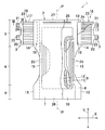
- FIG. 1 is a plan view of a so-called open-type disposable diaper, a part of which is broken for explanation.
- the diaper 1 includes a liquid-absorbing chassis 2 and fastening means 3 formed on the chassis 2.
- the chassis 2 forms front and rear waist regions 4 and 5 continuous in the longitudinal direction Y, and a crotch region 6 positioned between the front and rear waist regions 4 and 5.
- the chassis 2 includes an inner surface sheet 7 that forms a body side inner surface, an outer surface sheet 8 that forms a clothing side outer surface, a liquid absorbing structure 9 interposed between the inner and outer surface sheets 7 and 8, and a liquid absorbing structure.
- a leak-proof sheet 10 interposed between the body 9 and the outer sheet 8.
- the inner sheet 7 can be a breathable nonwoven fabric or the like.
- the liquid absorbing structure 9 includes, for example, a core material 11 made of a mixture of fluff pulp and superabsorbent polymer particles, and a tissue paper 12 enclosing the core material 11.
- the leak-proof sheet 10 has a size that can cover at least the liquid-absorbing structure 9, and can prevent leakage from the liquid-absorbing structure 9 to the clothing side.
- a liquid-impervious plastic film or the like can be used.
- the outer sheet 8 a general nonwoven fabric such as an air-through nonwoven fabric, a spunbond nonwoven fabric, or a point bond nonwoven fabric can be used.
- a spunbond nonwoven fabric and a point bond nonwoven fabric are used.
- the air-through nonwoven fabric is bulky as compared with the spunbond nonwoven fabric and the point bond nonwoven fabric, and since the fiber length is short and the number of interlaced fabrics is small, the air-through nonwoven fabric may be broken by engagement with the hook element.
- the outer sheet 8 various types can be selected according to the characteristics. However, even if any nonwoven fabric is used, the fibers are formed so as to be oriented in the longitudinal direction Y.
- the chassis 2 forms an almost hourglass shape by the inner and outer surface sheets 7 and 8, and is symmetrical to the longitudinal center line PP that bisects the transverse direction X.
- Such a chassis 2 includes a front edge 13, a rear edge 14 and a crotch edge 15 which face the lateral direction X and extend in the longitudinal direction Y in each of the front waist region 4, the rear waist region 5 and the crotch region 6. including.
- the crotch side edge 15 is cut out in a concave shape with respect to the front and rear side edges 13 and 14, thereby forming an hourglass shape.
- the flap 16 is joined to the rear edge 14.
- the flap 16 is formed of two flap sheets 17 and 18 having substantially the same shape and size.
- a liquid-impermeable nonwoven fabric can be used.
- Part of the sheets 17 and 18 are joined to the inner sheet 7 and the outer sheet 8 by welding or adhesion, respectively, at the rear edge portion 14 to form a joint portion 19 that joins the flap 16 and the chassis 2.
- the joint portion 19 is formed so as to extend in the longitudinal direction Y along the rear edge portion 14.
- the flap 16 joins the reinforcing sheet 20 to the sheet 17 by welding or adhesion on the outer side in the lateral direction X facing the joint portion 19.
- the reinforcing sheet 20 includes first and second hook elements 21 and 22. The first and second hook elements 21 and 22 are separated from each other in the longitudinal direction Y.
- a stretchable portion 23 that can be stretched in the lateral direction X is formed between the joint portion 19 of the flap 16 and the reinforcing sheet 20, a stretchable portion 23 that can be stretched in the lateral direction X is formed.
- the elastic part 23 is formed by attaching a plurality of flap elastic members 24 extending in the lateral direction X in an extended state.
- the plurality of flap elastic members 24 are spaced apart from each other at substantially equal intervals in the longitudinal direction Y, and are attached between the sheets 17 and 18 and joined to at least one of these sheets 17 and 18 by welding or adhesion. . Since the flap elastic member 24 is not attached to the joint portion 19, at least the joint portion 19 forms a non-stretchable portion inside the stretchable portion 23 in the lateral direction X.
- the non-stretchable portion does not need to be formed only by the joint portion 19.
- a non-stretchable part may be formed also by the part which is the chassis 2 located inside the horizontal direction X, and other elastic members are not attached.
- a plurality of leg-around elastic members 25 extending in the longitudinal direction Y are attached between the outer surface sheet 8 and the leak-proof sheet 10 inside the crotch side edge 15 of the chassis 2 in the lateral direction X.
- the plurality of leg-around elastic members 25 are attached to each other in a stretched state spaced apart from each other in the lateral direction X.
- the leg-around elastic member 25 needs to extend in the longitudinal direction Y at least in the crotch region 6.
- the leg elastic member 25 can fit the crotch region 6 around the leg when the diaper 1 is worn, and prevents leakage of urine and the like from around the leg.
- the stretchable portion 23 formed by the flap elastic member 24 is positioned outside the leg-around elastic member 25 in the lateral direction X.
- the chassis 2 includes front and rear end portions 26 and 27 that are formed in the front and rear waist regions 4 and 5 and extend in the horizontal direction X so as to face the vertical direction Y, respectively.
- a plurality of elastic waist members 28 extending in the lateral direction X are attached to the rear end portion 27 in an extended state.
- the plurality of waist elastic members 28 are separated from each other in the longitudinal direction Y and are joined between the inner surface sheet 7 and the leak-proof sheet 10 by adhesion or welding.
- the waist elastic member 28 allows the diaper 1 to be fitted to the wearer's waist and prevents leakage from the waist.
- the waist elastic member 28 is attached to a substantially central portion of the rear end portion 27, and both lateral ends thereof do not reach the joint portion 19.
- a non-stretchable portion can be formed together with the joint portion 19 by a portion where the waist elastic member 28 is not attached to the inside of the joint portion 19 in the lateral direction X.
- FIG. 2 is a diagram showing a wearing state of the diaper 1.
- the first and second hook elements 21 and 22 of the flap 16 are engaged with the outer sheet 8 to connect the front and rear waist regions 4 and 5 in the circumferential direction. That is, the nonwoven fabric which is the outer surface sheet 8 is used as the target of the first and second hook elements 21 and 22, and the fastening means 3 is formed by the first and second hook elements 21 and 22 and the outer surface sheet 8. I am going to do that.
- the first and second hook elements 21 and 22 When the first and second hook elements 21 and 22 are engaged with the outer sheet 8 as described above, the first and second hook elements 21 and 22 or the reinforcing sheet 20 of the flap 16 is placed on the longitudinal center line PP side. pull. When the first and second hook elements 21 and 22 or the reinforcing sheet 20 are pulled, the flap elastic member 24 continuous thereto is extended. After the first and second hook elements 21 and 22 and the outer sheet 8 are engaged, the flap elastic member 24 acts so as to contract in the lateral direction X. When the flap elastic member 24 contracts, the first and second hook elements 21, 22 are pulled toward the flap elastic member 24, and a shearing force is generated between the outer surface sheet 8.
- the outer sheet 8 is oriented in the longitudinal direction Y, the first and second hook elements 21 and 22 are caught so as to bite into the fibers of the outer sheet 8.
- these engagement forces can be strengthened, and these engagements can be made difficult to peel off at the time of wearing.
- the engagement force between the first and second hook elements 21 and 22 and the outer surface sheet 8 is different depending on the expansion and contraction stress caused by the flap elastic member 24 of the expansion and contraction part 23. It is desirable to set it to 5.0 N or less. When the stretching stress is smaller than 0.2N, the engagement force between the first and second hook elements 21 and 22 and the outer sheet 8 hardly increases and remains weak. End up. When the stretching stress is greater than 5.0 N, the tightening force on the wearer's entire waist increases, causing skin troubles or the wearer feeling tightness.
- Table 1 shows the relationship between the strength of the shearing force between the first and second hook elements 21 and 22 and the outer surface sheet 8 and the engaging force.
- a and B which are spunbond nonwoven fabrics, as the sample nonwoven fabric, the average value is shown by measuring 30 times for each nonwoven fabric.
- Sample nonwoven fabrics A and B have different basis weights and have different tendencies of engagement force with hook elements.
- the engagement force was measured as follows. The hook element is cut to a length of 100 mm and a width of 30 mm, and the target fiber nonwoven fabric is cut to a length of 150 mm and a width of 50 mm. The cut fiber nonwoven fabric is placed on a test stand, and a hook element is placed on the fiber nonwoven fabric.
- a 700 g roller is reciprocated once from the top of the hook element to engage the non-woven fabric with the hook element.
- a shear force of 100 g, 300 g or 500 g is applied to the fiber nonwoven fabric and the hook element for 10 seconds. Peeling was performed at a speed of 300 mm / min with respect to the test stand at a speed of 300 mm / min, and the engagement force (N) between the hook element and the fiber nonwoven fabric was measured from the resistance acting when peeling.
- the shear force is 0 g, that is, the case where no shear force is applied is also measured.
- the shear force is 0 g, a plurality of samples having an engagement force of 0.02 N or less are confirmed. Since it has been experimentally clarified that the fiber nonwoven fabric and the hook element are peeled off when the engagement force is 0.02 N or less, the shear force is at least 20 g, preferably 100 g or more and 500 g or less. .
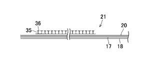
- FIG. 3 is an enlarged cross-sectional view taken along the line III-III in FIG. 1, and FIG. 4 is an enlarged partial plan view of the first hook element 21.
- the first hook element 21 includes a shaft portion 35 orthogonal to the reinforcing sheet 20 and a flange portion 36 orthogonal to the shaft portion 35.
- the flange portion 36 forms a substantially oval shape, and is disposed horizontally long so that the long diameter D is parallel to the horizontal direction X.
- Table 2 shows the measurement results of the engaging force between the hook element and the fiber nonwoven fabric due to the difference in the arrangement of the flanges 36.
- the measurement of the engagement force is the same as the measurement in Table 1, but the shearing force applied to the fiber nonwoven fabric and the hook element is 300 g.
- Sample 1 shown in Table 2 is a case of the present embodiment in which the flange portion 36 is disposed horizontally long so that the long diameter D is parallel to the horizontal direction X.
- Sample 2 has the long diameter D parallel to the vertical direction Y. This is a case where they are arranged vertically.
- the engaging force with the fiber nonwoven fabric forming the outer sheet 8 was 0.09N, and in the case of the vertically long sample 2, it was 0.02N.
- the collar portion 36 is disposed so as to be horizontally long, the engagement force is about 4.5 times higher than when the collar portion 36 is disposed so as to be vertically long. It is inferred that by arranging the ridges 36 so as to be horizontally long, more fibers can be bitten by the fiber nonwoven fabric in which the fibers are oriented in the longitudinal direction Y.
- the engagement with the hook element can be strengthened, and the flange portion of the substantially elliptical hook element is horizontally long.
- the engaging force can be further strengthened.
- the expansion / contraction part 23 which can be expanded-contracted in the horizontal direction X inside the horizontal direction X of a hook element, a hook element and a target fiber nonwoven fabric can be engaged reliably. Therefore, it is possible to prevent the engagement between the hook element and the target fiber nonwoven fabric from being peeled off.
- the hook element it is desirable to use a mechanical fastener made of polyolefin resin.
- the present invention is not limited to this, and various shapes of the flange 36 can be used. Even when the collar portion 36 of any shape is used, since the fiber orientation of the fiber nonwoven fabric is set along the longitudinal direction Y, the engagement force can be increased. Since the engagement between the hook element and the target fiber nonwoven fabric can be strengthened, any fiber nonwoven fabric can be used as the target and is not limited to any fiber nonwoven fabric.
- the flap elastic member 24 may be a general rubber such as a thread rubber or a flat rubber, or may be an elastic film.
- the stretchable portion 23 becomes thick, which may deteriorate the feeling of wearing and breathability, resulting in high costs. These problems are particularly noticeable in an adult diaper having a large diaper 1 and a large area of the flap 16. Therefore, when using an elastic film, it is desirable to use a belt-like film and to dispose them separately.
- a stretchable nonwoven fabric can be used instead of the elastic member. Also in this case, it is preferable to use a belt-like stretchable nonwoven fabric in consideration of wearing feeling and air permeability.
- the stretchable portion 23 can also be formed by combining a stretchable nonwoven fabric and a non-stretchable nonwoven fabric.
- an elastic nonwoven fabric what mixed PP fiber and urethane fiber, for example can be used.
- the stretchable portion 23 can be formed by bonding a non-stretchable nonwoven fabric to the stretched stretchable nonwoven fabric.
- the flap elastic member 24 is not attached to the joint portion 19 inside the stretchable portion 23 in the lateral direction X, and forms a non-stretchable portion.
- the wearing of the diaper 1 can be facilitated by making the joint portion 19 a non-stretchable portion. That is, for example, when wearing a diaper lying on the bed, the diaper 1 is inserted between the wearer's heel and the bed and the flap 16 is pulled to adjust the positional relationship with the heel, The second hook elements 21 and 22 are engaged with the outer sheet 8.
- a large tensile force acts on the flap 16, but if an elastic member is attached across the left and right flaps 16, no matter how much the flaps 16 are pulled, the position of the heel cannot be adjusted. . There is also a possibility that the flap 16 will be pulled too much and this will break.
- a non-stretchable part is formed.
- the position can be adjusted by directly holding the non-stretchable portion.
- the joint portion 19 is formed by four sheets of flap sheets 17 and 18 that form the flap 16 and inner and outer surface sheets 7 and 8 that form the rear waist region 5. Even if it breaks, it will not be torn.
- the flap 16 is provided separately from the chassis 2, but the first and second hook elements 21, 22 and the stretchable part 23 may be formed directly on the chassis 2.
- the flap elastic member 24 is formed outside the leg elastic member 25 in the lateral direction X. Therefore, when the diaper 1 is worn, the flap elastic member 24 is a U-shaped leg along the leg circumference. The surrounding elastic member 25 is positioned between both ends. By locating in this way, the flap elastic member 24 and the leg-surrounding elastic member 25 are apparently connected to each other so as to surround the leg leg in a substantially annular shape. When the wearer wears the diaper 1 and squats down, the leg ring of the diaper 1 is greatly expanded. Distributed. In addition, by forming leg leg by the leg-around elastic member 25 and the flap elastic member 24, it is possible to increase the amount of leg leg extension, and the whole leg leg can follow the movement of the wearer.
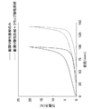
- FIG. 5 shows the measurement of the displacement with respect to the tensile force when the leg leg is formed only by the leg elastic member and when the leg leg is formed by the leg elastic member and the flap elastic member.
- a worn state that is, in a state where the first and second hook elements are engaged with the outer sheet which is the target nonwoven fabric
- two measuring bars are inserted into the leg supports, and one of the measuring bars is fixed and the other Are moved in directions away from each other, and the tensile force (N) applied to the measuring rod at this time and the displacement (mm) of the leg support of the diaper are measured.
- the solid line indicates only the leg elastic member
- the broken line indicates that the leg elastic member and the flap elastic member form a leg leg.
- the amount of displacement hardly changes, but when 5N, the amount of displacement is about 75 mm in the case of only the leg elastic member.
- the length of the elastic member is about 125 mm, which is about 1.7 times longer.
- leg leg by forming leg leg by the leg elastic member 25 and the flap elastic member 24, the tension force is not concentrated on the flap 16, and the first and second hook elements 21 and 22 and the outer sheet. It is possible to suppress the application of an excessive tensile force that shears the engagement portion with 8. Therefore, the first and second hook elements 21 and 22 and the outer surface sheet 8 are not detached from each other when worn, and the front and rear waist regions 4 and 5 are not disconnected.
- the positional relationship between the leg elastic member 25 and the flap elastic member 24 along the leg circumference may be slightly shifted, but in most cases, the leg members are surrounded by the elastic members 24 and 25. It comes to be. In order to surround the leg rest with the leg elastic member 25 and the flap elastic member 24, it is not necessary to be completely annular, and the elastic members 24, 25 may be slightly separated or overlapped.
- the leg elastic member 25 is attached so as to be a straight line, but may be formed to be curved along the shape of the crotch side edge 15.
- the leg-hole elastic member 25 can be curved on the front edge 13 side and straight on the rear edge 14 side. In this case, a non-stretchable portion can be formed in combination with the joint portion 19 on the rear edge portion 14 side.
- the coupling site with the hook element can be maintained flexibly, and the wearing feeling can be hindered. Absent.
- a fiber nonwoven fabric as the target, it is possible to reduce the sound when the hook element is peeled from the target.
- the outer sheet 8 is formed of the target fiber nonwoven fabric, it is not necessary to use a loop element, and the cost can be reduced accordingly. Since the entire outer sheet 8 is the target, the engaging position of the hook element is not restricted, and the hook element can be freely engaged in accordance with the wearer's physique and the like. In addition, since the engagement between the hook element and the target nonwoven fabric can be strengthened, various types of nonwoven fabrics can be targeted without using a special nonwoven fabric.
- FIG. 6 shows a second embodiment.
- a leak-proof cuff 29 is further provided on the body-side inner surface of the inner sheet 7.
- Another feature is the attachment position of the flap elastic member 24.
- the second embodiment is the same as the first embodiment, and the description of the same components is omitted.
- the leak-proof cuff 29 extends in the vertical direction Y across the front and rear end portions 26 and 27 of the chassis 2 and is formed symmetrically with respect to the vertical center line PP and is opposed to the horizontal direction X.
- the leak-proof cuff 29 includes inner and outer edges 30 and 31 facing the lateral direction X and extending in the longitudinal direction Y, and front and rear end edges 32 and 33 facing the longitudinal direction Y and extending in the lateral direction X.
- the outer edge 31 is joined to the inner sheet 7 to form a fixed edge, and the inner edge 30 is a free edge without joining.
- the inner edge 30 is folded outward in the lateral direction X and joined to the inner sheet 7 at the front and rear end edges 32 and 33.
- a cuff elastic member 34 extending in the longitudinal direction Y is attached to the inner edge 30 in an extended state.
- the free edge portion is separated so as to stand up from the inner surface sheet 7 and functions to prevent leakage of urine and the like.
- the plurality of flap elastic members 24 are arranged such that their attachment intervals are different in the vertical direction Y. That is, the interval between the flap elastic members 24 is narrow at the lower side of the flap 16 and the interval is increased at the upper side of the drawing. By narrowing the interval between the flap elastic members 24 in the lower part of the drawing, even when the flap 16 is pulled with an equal force, the body tightening force by the diaper 1 is large under the flap 16, that is, in the vicinity of the legrest. Become. On the other hand, the fastening force by the diaper 1 is relatively small above the flap 16, that is, at the waist side. For example, for people who often lie on a bed or the like, wear diapers 1 with emphasis on leakage prevention, so that the tightening force on the leg support side is increased as in this embodiment. Can do.
- the interval between the flap elastic members 24 is narrowed below the flap 16, but may be narrowed above the flap 16.
- the body can be moved freely, which is effective for a person who can stand or sit. That is, since a moving person places more importance on the displacement of the diaper 1 than prevention of leakage, the tightening on the waist side is often increased.
- a feeling of wear according to the wearer can be realized by changing the extensional stress of the expansion / contraction part 23 of the flap 16 above and below.
- a method of changing the extension magnification of the flap elastic member 24 in the vertical direction Y can be considered.
- the expansion ratio can be increased compared to other members, and when attempting to decrease the extension stress, the expansion ratio can be decreased as compared to other members. it can.
- a method of changing the thickness of the flap elastic member 24 is also conceivable.
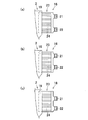
- FIG. 7A As another means for changing the extension stress of the expansion / contraction part 23, a method of changing the positions of the first and second hook elements 21, 22 as shown in FIG.
- the first and second hook elements 21 and 22 are located at substantially the same position from the upper and lower ends of the flap 16, and the elongation stress in the vertical direction is substantially equal.
- FIG. 7B when the second hook element 22 is positioned above the vertical direction Y of the flap 16, that is, on the first hook element 21 side, Elongation stress increases.
- FIG. 6C when the first hook element 21 is positioned below the vertical direction Y of the flap 16, that is, on the second hook element 22 side, the elongation stress is large above the flap 16. Become.
- the extension stress of the expansion / contraction part 23 can be changed, the thing of the extension stress according to a wearer's physique, a lifestyle, etc. can be selected, and the wear feeling according to each wearer Can be realized.
Abstract
Description
ターゲット繊維不織布として、これを構成する繊維長が比較的短いエアスルー不織布を用いることとしているが、エアスルー不織布とフック要素とを係合させた後、着用者が座ったりした場合に、エアスルー不織布が破れてしまうという問題があった。すなわち、着用者の上記のような動きによっておむつの脚刳りが広げられ、これに伴って連結した前後ウエスト域も横方向に引っ張られる。前後ウエスト域が引っ張られると、係合したエアスルー不織布とフック要素との間にせん断方向に過大な引張力が発生し、エアスルー不織布が破れてしまうことがあった。エアスルー不織布は繊維長が短く、互いに交絡している数が少ないからである。
また、ターゲット繊維不織布がエアスルー不織布に限定されるので、他の使用目的に応じた不織布の選択ができないという問題があった。
2 シャーシ
3 ファスニング手段
4 前ウエスト域
5 後ウエスト域
6 股下域
7 内面シート
8 外面シート
13 前側縁部
14 後側縁部
19 接合部(非伸縮部)
21 第1フック要素
22 第2フック要素
23 伸縮部
24 フラップ弾性部材
図1~4は、本発明の第1の実施形態を示したものである。図1は、いわゆるオープンタイプの使い捨ておむつの平面図であり、説明のためその一部を破断させている。おむつ1は、吸液性のシャーシ2と、シャーシ2に形成されたファスニング手段3とを含む。シャーシ2は、縦方向Yに連続する前後ウエスト域4,5と、前後ウエスト域4,5の間に位置する股下域6とを形成している。このシャーシ2は、身体側内面を形成する内面シート7と、着衣側外面を形成する外面シート8と、これら内外面シート7,8の間に介在させた吸液構造体9と、吸液構造体9と外面シート8との間に介在させた防漏シート10とを含む。
フラップ弾性部材24によって形成される伸縮部23は、脚周り弾性部材25よりも横方向Xの外側に位置するようにしている。
ウエスト弾性部材28は、後端部27のほぼ中央部分に取り付けられ、その横方向の両端は、接合部19までは達していない。接合部19の横方向Xの内側においてウエスト弾性部材28が取り付けられていない部分によって、接合部19と相まって非伸縮部を形成することもできる。
係合力の測定は、以下の通りにおこなった。フック要素は長さ100mm、幅30mmに切断し、ターゲットとなる繊維不織布は長さ150mm、幅50mmに切断する。切断した繊維不織布を試験台に載せ、この繊維不織布にフック要素を載せる。フック要素の上から700gのローラを一往復させ、繊維不織布とフック要素とを係合させる。繊維不織布とフック要素とに100g、300gまたは500gのせん断力を10秒間加える。試験台に対して135°の方向で速度300mm/minでピーリングを行い、そのピーリングをした際に作用する抵抗からフック要素と繊維不織布との係合力(N)を測定した。

せん断力が0gの場合には、係合力が0.02N以下であるサンプルが複数確認される。係合力が0.02N以下の場合には繊維不織布とフック要素とが剥がれてしまうことが実験的に解明されていることから、せん断力は少なくとも20g以上とし、100g以上500g以下とすることが好ましい。

フック要素とターゲット繊維不織布との係合を強固にすることができるので、どのような繊維不織布でもターゲットとして用いることができ、いずれかの繊維不織布に限定されることがない。
伸縮部23を伸縮性不織布と非伸縮性不織布とを複合させた構造とすることによって形成することもできる。伸縮性不織布として、例えばPP繊維とウレタン繊維とを混繊したものを用いることができる。この場合、ストレッチさせた伸縮性不織布に非伸縮性不織布を貼りあわせることによって伸縮部23を形成することができる。
図6は第2の実施形態を示したものである。
この第2の実施形態における特徴のひとつは、内面シート7の身体側内面に、更に防漏カフ29を備えていることである。他の特徴はフラップ弾性部材24の取り付け位置にある。これら特徴以外は第1の実施形態と同様であり、同様の構成要素についてはその説明を省略する。
フラップ16の伸縮部23の伸長応力をその上下において変化させることによって、着用者に応じた着用感を実現することができる。
Claims (6)
- 縦方向および横方向と、身体側内面および着衣側外面と、前ウエスト域、後ウエスト域、前後ウエスト域間に位置する股下域とを含むシャーシと、前記前後ウエスト域の前記横方向に対向し前記縦方向に延びる側縁部を互いに着脱可能に連結するファスニング手段とを含み、前記ファスニング手段により前記前後ウエスト域が周方向に連結される着用物品において、
前記ファスニング手段は、前記前後ウエスト域のいずれか一方に形成されたフック要素と、前記前後ウエスト域のいずれか他方に形成され前記フック要素と着脱可能に係合するターゲット繊維不織布とを含むとともに、
前記フック要素の前記横方向内側において、同横方向に伸縮可能な伸縮部を形成することを特徴とする前記着用物品。 - 前記シャーシは、前記身体側内面を形成する内面シートと、前記着衣側外面を形成する外面シートとを含み、
前記外面シートは、前記ターゲット繊維不織布によって形成される請求項1記載の着用物品。 - 前記伸縮部の前記横方向内側には、伸縮性を有しない非伸縮部が同伸縮部と連続して形成される請求項1または2に記載の着用物品。
- 前記ターゲット繊維不織布は、前記縦方向に繊維が配向する請求項1~3のいずれかに記載の着用物品。
- 前記シャーシは、前記側縁部に前記縦方向に伸長状態で取り付けられた脚周り弾性部材を含み、前記伸縮部は、前記着用物品の着用時において前記脚周り弾性部材と相まって略環状を形成する請求項1記載の着用物品。
- 前記伸縮部は複数本の弾性部材または帯状伸縮性不織布を含み、前記弾性部材または前記帯状伸縮性不織布は、前記縦方向に離間して前記横方向に延びて伸長状態で取り付けられる請求項1または5に記載の着用物品。
Priority Applications (6)
| Application Number | Priority Date | Filing Date | Title |
|---|---|---|---|
| EP08872157.6A EP2246020B1 (en) | 2008-02-04 | 2008-11-20 | Wearing article |
| US12/865,906 US8663185B2 (en) | 2008-02-04 | 2008-11-20 | Wearing article |
| BRPI0820515-9A BRPI0820515A2 (pt) | 2008-02-04 | 2008-11-20 | "artigo do vestuário" |
| AU2008349938A AU2008349938B2 (en) | 2008-02-04 | 2008-11-20 | Wearing article |
| CN200880128074.6A CN101969907B (zh) | 2008-02-04 | 2008-11-20 | 穿着用物品 |
| KR1020107019504A KR101536721B1 (ko) | 2008-02-04 | 2008-11-20 | 착용물품 |
Applications Claiming Priority (2)
| Application Number | Priority Date | Filing Date | Title |
|---|---|---|---|
| JP2008-024451 | 2008-02-04 | ||
| JP2008024451A JP5328168B2 (ja) | 2008-02-04 | 2008-02-04 | 着用物品 |
Publications (1)
| Publication Number | Publication Date |
|---|---|
| WO2009098811A1 true WO2009098811A1 (ja) | 2009-08-13 |
Family
ID=40951895
Family Applications (1)
| Application Number | Title | Priority Date | Filing Date |
|---|---|---|---|
| PCT/JP2008/071079 WO2009098811A1 (ja) | 2008-02-04 | 2008-11-20 | 着用物品 |
Country Status (8)
| Country | Link |
|---|---|
| US (1) | US8663185B2 (ja) |
| EP (1) | EP2246020B1 (ja) |
| JP (1) | JP5328168B2 (ja) |
| KR (1) | KR101536721B1 (ja) |
| CN (1) | CN101969907B (ja) |
| AU (1) | AU2008349938B2 (ja) |
| BR (1) | BRPI0820515A2 (ja) |
| WO (1) | WO2009098811A1 (ja) |
Cited By (1)
| Publication number | Priority date | Publication date | Assignee | Title |
|---|---|---|---|---|
| JP2014073251A (ja) * | 2012-10-04 | 2014-04-24 | Uni Charm Corp | 着用物品 |
Families Citing this family (17)
| Publication number | Priority date | Publication date | Assignee | Title |
|---|---|---|---|---|
| BRPI0622115B8 (pt) * | 2006-11-07 | 2021-06-22 | Essity Hygiene & Health Ab | artigo absorvente |
| JP5549252B2 (ja) * | 2010-02-08 | 2014-07-16 | 王子ホールディングス株式会社 | テープ型使い捨ておむつ |
| WO2012073901A1 (ja) * | 2010-11-30 | 2012-06-07 | 花王株式会社 | 使い捨ておむつ及びその製造方法 |
| JP2012120571A (ja) * | 2010-12-06 | 2012-06-28 | Kao Corp | 伸縮性シートの製造方法 |
| JP5787689B2 (ja) * | 2011-09-16 | 2015-09-30 | ユニ・チャーム株式会社 | 使い捨て着用物品 |
| US9993374B2 (en) * | 2011-11-10 | 2018-06-12 | Kimberly-Clark Worldwide, Inc. | Absorbent personal care article having intermeshing flaps |
| US9566198B2 (en) | 2013-03-15 | 2017-02-14 | Dsg Technology Holdings Ltd. | Method of making an absorbent composite and absorbent articles employing the same |
| AU2014233680C1 (en) * | 2013-03-15 | 2018-10-18 | Dsg Technology Holdings Ltd. | Absorbent articles with pulpless riffled core |
| US9789014B2 (en) | 2013-03-15 | 2017-10-17 | Dsg Technology Holdings Ltd. | Method of making an absorbent composite and absorbent articles employing the same |
| CA3186021A1 (en) | 2013-07-03 | 2015-01-08 | Dsg Technology Holdings Limited | An absorbent composite, an absorbent article employing the same, and methods, systems, and apparatus for making the absorbent composite and/or article |
| JP2014036902A (ja) * | 2013-11-27 | 2014-02-27 | Uni Charm Corp | 使い捨ての着用物品 |
| DE112014006398T5 (de) * | 2014-03-28 | 2016-12-22 | Kimberly-Clark Worldwide, Inc. | Absorptionsartikel mit einem Befestigungssystem mit reduziertem Abfall und Verfahren zu dessen Herstellung |
| JP6239052B1 (ja) * | 2016-06-30 | 2017-11-29 | ユニ・チャーム株式会社 | 吸収性物品 |
| JP6239053B1 (ja) * | 2016-06-30 | 2017-11-29 | ユニ・チャーム株式会社 | 吸収性物品 |
| JP7174643B2 (ja) * | 2019-02-18 | 2022-11-17 | ユニ・チャーム株式会社 | 吸収性物品 |
| ES2945646T3 (es) * | 2021-02-22 | 2023-07-05 | Fameccanica Data Spa | Un laminado elástico continuo extensible transversalmente y procedimiento para su producción |
| EP4301300A1 (en) * | 2021-03-02 | 2024-01-10 | Essity Hygiene and Health Aktiebolag | Disposable absorbent hygiene article |
Citations (8)
| Publication number | Priority date | Publication date | Assignee | Title |
|---|---|---|---|---|
| JPH01168510U (ja) * | 1988-05-13 | 1989-11-28 | ||
| JPH06507800A (ja) * | 1991-05-20 | 1994-09-08 | ザ、プロクター、エンド、ギャンブル、カンパニー | 再締結自在の締結装置用不織雌部品およびその製法 |
| JP2001087309A (ja) * | 1999-09-28 | 2001-04-03 | Daio Paper Corp | 使い捨て紙おむつ |
| JP2003180748A (ja) | 2001-12-17 | 2003-07-02 | Daio Paper Corp | 不織布製ターゲットテープおよびこれを用いた吸収性物品 |
| JP2005046225A (ja) * | 2003-07-30 | 2005-02-24 | Uni Charm Corp | 使い捨ておむつ |
| JP2005245555A (ja) * | 2004-03-02 | 2005-09-15 | Daio Paper Corp | 使い捨て紙おむつ |
| JP2005287821A (ja) * | 2004-03-31 | 2005-10-20 | Uni Charm Corp | ウエスト締結手段を有する着用物品 |
| WO2007002929A2 (en) * | 2005-06-29 | 2007-01-04 | The Procter & Gamble Company | Disposable absorbent article containing an unapertured skinless elastomeric layer |
Family Cites Families (18)
| Publication number | Priority date | Publication date | Assignee | Title |
|---|---|---|---|---|
| JPS60199903A (ja) * | 1984-03-17 | 1985-10-09 | 本州キノクロス株式会社 | 使捨ておむつ |
| JPH01168510A (ja) | 1987-12-24 | 1989-07-04 | Tokico Ltd | 車高調整装置 |
| GB2327857B (en) * | 1997-08-01 | 2001-09-26 | Ykk Europ Ltd | A disposable nappy |
| US6589638B1 (en) * | 1997-09-15 | 2003-07-08 | Kimberly-Clark Worldwide, Inc. | Stretch-pillowed bulked laminate useful as an ideal loop fastener component |
| US6045543A (en) * | 1997-11-05 | 2000-04-04 | Kimberly-Clark Worldwide, Inc. | Alignment indicators for use with personal care articles |
| EP0979639A1 (en) * | 1998-08-13 | 2000-02-16 | The Procter & Gamble Company | Method for making fibrous loop member |
| JP4073613B2 (ja) * | 2000-09-01 | 2008-04-09 | ユニ・チャーム株式会社 | 連続フィラメントを有する裏面シートを用いた吸収性物品 |
| US20030069557A1 (en) * | 2001-10-10 | 2003-04-10 | Stacy Driskell | Absorbent garment with integrated elastiziced connector tabs and waistline |
| WO2003034966A1 (en) * | 2001-10-25 | 2003-05-01 | The Procter & Gamble Company | Disposable absorbent article comprising landing zone graphics |
| US6692477B2 (en) * | 2001-12-12 | 2004-02-17 | Paragon Trade Brands, Inc. | Absorbent garment tab having zones of different elasticity |
| US8007485B2 (en) * | 2001-12-31 | 2011-08-30 | Kimberly-Clark Worldwide, Inc. | Mechanical fastening system for an absorbent article |
| JP3830472B2 (ja) * | 2003-07-24 | 2006-10-04 | 花王株式会社 | 吸収性物品 |
| WO2005079720A1 (ja) * | 2004-02-23 | 2005-09-01 | Zuiko Corporation | 着用物品およびその製造方法 |
| US20060058772A1 (en) * | 2004-09-10 | 2006-03-16 | Hamzeh Karami | Absorbent article having a loopless fastening system |
| US20060241560A1 (en) * | 2005-04-22 | 2006-10-26 | Chang Kuo-Shu E | Convertible absorbent article with extensible side panels |
| JP2007075277A (ja) * | 2005-09-13 | 2007-03-29 | Livedo Corporation | 使い捨ておむつ |
| US20070066950A1 (en) * | 2005-09-21 | 2007-03-22 | Nelson Todd L | Disposable absorbent garment with elastic ears |
| WO2007059933A2 (de) * | 2005-11-23 | 2007-05-31 | Wilfried Fenske | Anatomisch geformte, hochelastische elemente für babywindeln und inkontinenzprodukte |
-
2008
- 2008-02-04 JP JP2008024451A patent/JP5328168B2/ja active Active
- 2008-11-20 AU AU2008349938A patent/AU2008349938B2/en active Active
- 2008-11-20 EP EP08872157.6A patent/EP2246020B1/en not_active Not-in-force
- 2008-11-20 WO PCT/JP2008/071079 patent/WO2009098811A1/ja active Application Filing
- 2008-11-20 US US12/865,906 patent/US8663185B2/en not_active Expired - Fee Related
- 2008-11-20 BR BRPI0820515-9A patent/BRPI0820515A2/pt not_active IP Right Cessation
- 2008-11-20 KR KR1020107019504A patent/KR101536721B1/ko active IP Right Grant
- 2008-11-20 CN CN200880128074.6A patent/CN101969907B/zh active Active
Patent Citations (8)
| Publication number | Priority date | Publication date | Assignee | Title |
|---|---|---|---|---|
| JPH01168510U (ja) * | 1988-05-13 | 1989-11-28 | ||
| JPH06507800A (ja) * | 1991-05-20 | 1994-09-08 | ザ、プロクター、エンド、ギャンブル、カンパニー | 再締結自在の締結装置用不織雌部品およびその製法 |
| JP2001087309A (ja) * | 1999-09-28 | 2001-04-03 | Daio Paper Corp | 使い捨て紙おむつ |
| JP2003180748A (ja) | 2001-12-17 | 2003-07-02 | Daio Paper Corp | 不織布製ターゲットテープおよびこれを用いた吸収性物品 |
| JP2005046225A (ja) * | 2003-07-30 | 2005-02-24 | Uni Charm Corp | 使い捨ておむつ |
| JP2005245555A (ja) * | 2004-03-02 | 2005-09-15 | Daio Paper Corp | 使い捨て紙おむつ |
| JP2005287821A (ja) * | 2004-03-31 | 2005-10-20 | Uni Charm Corp | ウエスト締結手段を有する着用物品 |
| WO2007002929A2 (en) * | 2005-06-29 | 2007-01-04 | The Procter & Gamble Company | Disposable absorbent article containing an unapertured skinless elastomeric layer |
Non-Patent Citations (1)
| Title |
|---|
| See also references of EP2246020A4 * |
Cited By (1)
| Publication number | Priority date | Publication date | Assignee | Title |
|---|---|---|---|---|
| JP2014073251A (ja) * | 2012-10-04 | 2014-04-24 | Uni Charm Corp | 着用物品 |
Also Published As
| Publication number | Publication date |
|---|---|
| US20110046597A1 (en) | 2011-02-24 |
| EP2246020A1 (en) | 2010-11-03 |
| KR20100120677A (ko) | 2010-11-16 |
| JP2009183364A (ja) | 2009-08-20 |
| CN101969907B (zh) | 2014-08-06 |
| JP5328168B2 (ja) | 2013-10-30 |
| BRPI0820515A2 (pt) | 2015-06-16 |
| US8663185B2 (en) | 2014-03-04 |
| AU2008349938A1 (en) | 2009-08-13 |
| AU2008349938B2 (en) | 2014-06-05 |
| EP2246020B1 (en) | 2015-01-07 |
| CN101969907A (zh) | 2011-02-09 |
| KR101536721B1 (ko) | 2015-07-14 |
| EP2246020A4 (en) | 2011-12-28 |
Similar Documents
| Publication | Publication Date | Title |
|---|---|---|
| JP5328168B2 (ja) | 着用物品 | |
| JP3640356B2 (ja) | 使い捨ておむつ | |
| US7833207B2 (en) | Pants-type wearing article | |
| JP3652691B2 (ja) | 開放型の使い捨ておむつ | |
| TWI272939B (en) | Wearing article | |
| JP2004024434A (ja) | 開放型の使い捨て着用物品 | |
| JP2003153955A (ja) | 開放型の使い捨ておむつ | |
| TWI480031B (zh) | Wearing items and their folding methods | |
| JP4705405B2 (ja) | パンツ型の使い捨て着用物品 | |
| JP2006158607A (ja) | 使い捨てパンツ | |
| JP4284216B2 (ja) | 開閉式使い捨てパンツ | |
| JP5787689B2 (ja) | 使い捨て着用物品 | |
| JP3975083B2 (ja) | 開放型の使い捨て着用物品 | |
| JP4537263B2 (ja) | 使い捨て吸収性物品およびその製造方法 | |
| JP2005287930A (ja) | 使い捨ておむつ | |
| JP2003290288A5 (ja) | ||
| JP4482426B2 (ja) | 使い捨ておむつ | |
| KR20140135966A (ko) | 완전히 단절된 전방 패널을 갖는 조절 가능한 팬티형 일회용 속옷 | |
| KR101395522B1 (ko) | 착용 물품 | |
| JP2014217583A (ja) | パンツ型着用物品 | |
| JP2012139269A (ja) | 使い捨ておむつ | |
| JP2002263133A (ja) | 使い捨て着用物品 | |
| JP2003079665A (ja) | パンツ型使い捨て着用物品 | |
| JP2014237056A (ja) | 吸収性物品 | |
| JP2012115462A (ja) | 吸収性物品 |
Legal Events
| Date | Code | Title | Description |
|---|---|---|---|
| WWE | Wipo information: entry into national phase |
Ref document number: 200880128074.6 Country of ref document: CN |
|
| 121 | Ep: the epo has been informed by wipo that ep was designated in this application |
Ref document number: 08872157 Country of ref document: EP Kind code of ref document: A1 |
|
| NENP | Non-entry into the national phase |
Ref country code: DE |
|
| WWE | Wipo information: entry into national phase |
Ref document number: 3047/KOLNP/2010 Country of ref document: IN |
|
| WWE | Wipo information: entry into national phase |
Ref document number: 2008349938 Country of ref document: AU |
|
| WWE | Wipo information: entry into national phase |
Ref document number: 2008872157 Country of ref document: EP |
|
| ENP | Entry into the national phase |
Ref document number: 20107019504 Country of ref document: KR Kind code of ref document: A |
|
| ENP | Entry into the national phase |
Ref document number: 2008349938 Country of ref document: AU Date of ref document: 20081120 Kind code of ref document: A |
|
| WWE | Wipo information: entry into national phase |
Ref document number: 12865906 Country of ref document: US |
|
| ENP | Entry into the national phase |
Ref document number: PI0820515 Country of ref document: BR Kind code of ref document: A2 Effective date: 20100804 |