WO2012073901A1 - 使い捨ておむつ及びその製造方法 - Google Patents
使い捨ておむつ及びその製造方法 Download PDFInfo
- Publication number
- WO2012073901A1 WO2012073901A1 PCT/JP2011/077417 JP2011077417W WO2012073901A1 WO 2012073901 A1 WO2012073901 A1 WO 2012073901A1 JP 2011077417 W JP2011077417 W JP 2011077417W WO 2012073901 A1 WO2012073901 A1 WO 2012073901A1
- Authority
- WO
- WIPO (PCT)
- Prior art keywords
- panel
- stretchable
- main body
- tape
- elastic
- Prior art date
Links
Images


Classifications
-
- A—HUMAN NECESSITIES
- A61—MEDICAL OR VETERINARY SCIENCE; HYGIENE
- A61F—FILTERS IMPLANTABLE INTO BLOOD VESSELS; PROSTHESES; DEVICES PROVIDING PATENCY TO, OR PREVENTING COLLAPSING OF, TUBULAR STRUCTURES OF THE BODY, e.g. STENTS; ORTHOPAEDIC, NURSING OR CONTRACEPTIVE DEVICES; FOMENTATION; TREATMENT OR PROTECTION OF EYES OR EARS; BANDAGES, DRESSINGS OR ABSORBENT PADS; FIRST-AID KITS
- A61F13/00—Bandages or dressings; Absorbent pads
- A61F13/15—Absorbent pads, e.g. sanitary towels, swabs or tampons for external or internal application to the body; Supporting or fastening means therefor; Tampon applicators
- A61F13/56—Supporting or fastening means
-
- A—HUMAN NECESSITIES
- A61—MEDICAL OR VETERINARY SCIENCE; HYGIENE
- A61F—FILTERS IMPLANTABLE INTO BLOOD VESSELS; PROSTHESES; DEVICES PROVIDING PATENCY TO, OR PREVENTING COLLAPSING OF, TUBULAR STRUCTURES OF THE BODY, e.g. STENTS; ORTHOPAEDIC, NURSING OR CONTRACEPTIVE DEVICES; FOMENTATION; TREATMENT OR PROTECTION OF EYES OR EARS; BANDAGES, DRESSINGS OR ABSORBENT PADS; FIRST-AID KITS
- A61F13/00—Bandages or dressings; Absorbent pads
- A61F13/15—Absorbent pads, e.g. sanitary towels, swabs or tampons for external or internal application to the body; Supporting or fastening means therefor; Tampon applicators
- A61F13/45—Absorbent pads, e.g. sanitary towels, swabs or tampons for external or internal application to the body; Supporting or fastening means therefor; Tampon applicators characterised by the shape
- A61F13/49—Absorbent articles specially adapted to be worn around the waist, e.g. diapers
- A61F13/49007—Form-fitting, self-adjusting disposable diapers
- A61F13/49009—Form-fitting, self-adjusting disposable diapers with elastic means
- A61F13/49014—Form-fitting, self-adjusting disposable diapers with elastic means the elastic means is located at the side panels
- A61F13/49015—Form-fitting, self-adjusting disposable diapers with elastic means the elastic means is located at the side panels the elastic means being elastic panels
-
- A—HUMAN NECESSITIES
- A61—MEDICAL OR VETERINARY SCIENCE; HYGIENE
- A61F—FILTERS IMPLANTABLE INTO BLOOD VESSELS; PROSTHESES; DEVICES PROVIDING PATENCY TO, OR PREVENTING COLLAPSING OF, TUBULAR STRUCTURES OF THE BODY, e.g. STENTS; ORTHOPAEDIC, NURSING OR CONTRACEPTIVE DEVICES; FOMENTATION; TREATMENT OR PROTECTION OF EYES OR EARS; BANDAGES, DRESSINGS OR ABSORBENT PADS; FIRST-AID KITS
- A61F13/00—Bandages or dressings; Absorbent pads
- A61F13/15—Absorbent pads, e.g. sanitary towels, swabs or tampons for external or internal application to the body; Supporting or fastening means therefor; Tampon applicators
- A61F13/15577—Apparatus or processes for manufacturing
- A61F13/15756—Applying tabs, strips, tapes, loops; Knotting the ends of pads
-
- A—HUMAN NECESSITIES
- A61—MEDICAL OR VETERINARY SCIENCE; HYGIENE
- A61F—FILTERS IMPLANTABLE INTO BLOOD VESSELS; PROSTHESES; DEVICES PROVIDING PATENCY TO, OR PREVENTING COLLAPSING OF, TUBULAR STRUCTURES OF THE BODY, e.g. STENTS; ORTHOPAEDIC, NURSING OR CONTRACEPTIVE DEVICES; FOMENTATION; TREATMENT OR PROTECTION OF EYES OR EARS; BANDAGES, DRESSINGS OR ABSORBENT PADS; FIRST-AID KITS
- A61F13/00—Bandages or dressings; Absorbent pads
- A61F13/15—Absorbent pads, e.g. sanitary towels, swabs or tampons for external or internal application to the body; Supporting or fastening means therefor; Tampon applicators
- A61F13/45—Absorbent pads, e.g. sanitary towels, swabs or tampons for external or internal application to the body; Supporting or fastening means therefor; Tampon applicators characterised by the shape
- A61F13/49—Absorbent articles specially adapted to be worn around the waist, e.g. diapers
-
- A—HUMAN NECESSITIES
- A61—MEDICAL OR VETERINARY SCIENCE; HYGIENE
- A61F—FILTERS IMPLANTABLE INTO BLOOD VESSELS; PROSTHESES; DEVICES PROVIDING PATENCY TO, OR PREVENTING COLLAPSING OF, TUBULAR STRUCTURES OF THE BODY, e.g. STENTS; ORTHOPAEDIC, NURSING OR CONTRACEPTIVE DEVICES; FOMENTATION; TREATMENT OR PROTECTION OF EYES OR EARS; BANDAGES, DRESSINGS OR ABSORBENT PADS; FIRST-AID KITS
- A61F13/00—Bandages or dressings; Absorbent pads
- A61F13/15—Absorbent pads, e.g. sanitary towels, swabs or tampons for external or internal application to the body; Supporting or fastening means therefor; Tampon applicators
- A61F13/56—Supporting or fastening means
- A61F13/5622—Supporting or fastening means specially adapted for diapers or the like
- A61F13/5633—Supporting or fastening means specially adapted for diapers or the like open type diaper
-
- A—HUMAN NECESSITIES
- A61—MEDICAL OR VETERINARY SCIENCE; HYGIENE
- A61F—FILTERS IMPLANTABLE INTO BLOOD VESSELS; PROSTHESES; DEVICES PROVIDING PATENCY TO, OR PREVENTING COLLAPSING OF, TUBULAR STRUCTURES OF THE BODY, e.g. STENTS; ORTHOPAEDIC, NURSING OR CONTRACEPTIVE DEVICES; FOMENTATION; TREATMENT OR PROTECTION OF EYES OR EARS; BANDAGES, DRESSINGS OR ABSORBENT PADS; FIRST-AID KITS
- A61F13/00—Bandages or dressings; Absorbent pads
- A61F13/15—Absorbent pads, e.g. sanitary towels, swabs or tampons for external or internal application to the body; Supporting or fastening means therefor; Tampon applicators
- A61F13/56—Supporting or fastening means
- A61F13/62—Mechanical fastening means, ; Fabric strip fastener elements, e.g. hook and loop
- A61F13/622—Fabric strip fastener elements, e.g. hook and loop
Definitions
- the present invention relates to a disposable diaper and a manufacturing method thereof.
- a substantially vertically long absorbent body provided with a top sheet, a back sheet, and an absorbent body disposed between both sheets, and a pair provided on both side edges along the longitudinal direction of the absorbent body.
- a fastening portion of a fastening tape fixed to an outer edge portion along the longitudinal direction of the main body of each of the pair of elastic panels, and a non-skin-facing surface of the absorbent main body, 2.
- Patent Document 1 describes an unfolded disposable diaper having a stretchable side panel that includes a specific elastomer that slowly recovers.
- FIG. 6 of Patent Document 1 shows an example of the side panel.
- Patent Document 2 describes that the stretchable panel is composed of a breathable stretchable laminate containing polyurethane.
- Patent Document 3 includes a fixing portion fixed to the absorbent main body and a protruding portion protruding from the absorbent main body, and the protruding portion is based on a distal end portion having a fastening portion and the distal end portion.
- a fastening tape composed of an end-side main body portion it is described that a reinforcing non-woven fabric layer is fixed to the fixing portion, the fixing portion of the basic non-woven fabric layer and the front end portion extending over the main body portion and the front end portion.
- the elastic member is fixed in an extended state along the width direction of the main body so as to straddle the fixing portion and the main body portion and straddle the main body portion and the tip portion.
- Patent Document 5 has a support portion (absorbent main body) and a fastening tape as a deployable panel-type disposable diaper, and the fastening tape includes a tip portion, a main body portion, and a fixing portion. It describes what is provided in the width direction of the support part and is fixed to the support part by the fixing part.
- the fastening tape is provided with a plurality of elastic members continuously extending from the tip portion to the fixing portion via the main body portion, and each elastic member is in a non-expanded state at the tip portion and the fixing portion.
- the main body is bonded and fixed in a state of extending in the width direction.
- Patent Document 5 does not describe how to set the adhesive force of each of the front end portion, the main body portion, and the fixed portion of the fastening tape to the elastic member.
- the body shape of a person wearing a disposable diaper usually has an abdomen protruding forward and a dorsal side recessed, and a lower part of the abdomen protrudes rearward, and the presence of a base of the leg causes a lateral
- the width is larger than other parts.
- the degree of elongation when the fastening tape is pulled is relatively small.
- the crotch part of the diaper is located around the hip or leg around which the degree of protrusion is relatively large, the degree of expansion is relatively large.
- Conventional unfolded panel-type disposable diapers have a gap between the waist part and the waist part without being in close contact with the waist part on the back side of the wearer due to the imbalance in the degree of expansion of the stretchable panel when worn. This is likely to occur, and there is a risk of liquid leakage from the gap.
- the present invention relates to providing a disposable diaper that is difficult to be clamped.
- the present invention includes a top sheet, a back sheet, and a vertically long absorbent main body provided with an absorbent body interposed between the two sheets, and a pair of edges fixed to both side edges along the main body longitudinal direction of the absorbent main body.
- a fastening portion of a fastening tape fixed to an outer edge along the longitudinal direction of the body of each of the pair of stretch panels, and fastened to a non-skin facing surface of the absorbent body. It is a disposable diaper that is designed to be worn on.
- the stretchable panel has a stretchable portion that is stretchable in the width direction of the main body, inward of the widthwise direction of the main body from the outer edge, and the stretchable portion is extended to the panel material and the panel material.
- a plurality of elastic members that are fixed and extend in the width direction of the main body, and the plurality of elastic members are arranged at predetermined intervals in the longitudinal direction of the main body and include the outer edge portion.
- the fastening tape is configured to include a tape base material having the fastening portion, and the tape base material includes a tape base end portion fixed to the outer edge portion of the stretchable panel, and the tape base end.
- a tape front end portion that is connected to the outer peripheral portion and protrudes outward in the main body width direction from the outer edge portion and has the fastening portion
- the tape base end portion includes an outer end and an inner side along the main body width direction.
- the inner end is located on the inner side in the longitudinal direction of the main body with respect to the outer end, and the inner end is disposed on the innermost side in the longitudinal direction of the main body among the plurality of elastic members. Located outside the direction.
- the conventional unfolded panel type disposable diaper has a linear elastic member bonded to the panel material with an adhesive at the outer edge of the elastic panel to which the fastening tape attached to the elastic panel is fixed.
- the rigidity of the outer edge of the stretchable panel is increased, and the texture such as softness is deteriorated. Pulling the fastening tape at the time of wearing and trying to fix it to the adherence area on the abdomen may cause the outer edge of the stretchable panel to break, catching on clothes or hitting the skin of the wearer .
- a method of adhering the end of the thread-like elastic member with an adhesive having a narrow width is conceivable. When such a method is adopted, the elastic panel is attached when a diaper is mounted. If it is extended, the thread-like elastic member may come off, and the fixing stability of the elastic member is lowered.
- an object of the present invention relates to providing a disposable diaper having an outer edge portion of a stretchable panel having flexibility and excellent fixing stability of an elastic member constituting the stretchable panel.
- the present invention includes a top sheet, a back sheet, and a vertically long absorbent main body provided with an absorbent body interposed between the two sheets, and a pair of edges fixed to both side edges along the main body longitudinal direction of the absorbent main body.
- a disposable diaper having a stretchable panel, and a fastening tape fixed to an outer edge along the longitudinal direction of the body of each of the pair of stretchable panels, wherein the stretchable panel is fixed to the panel material and the panel material
- a plurality of elastic members extending in the width direction of the main body and having a stretchability in the width direction of the main body and a non-stretchable portion having no stretchability in the width direction of the main body
- the outer edge portion of the stretchable panel includes the non-stretchable portion, and a plurality of the elastic members are arranged at a predetermined interval in the longitudinal direction of the main body, and the panel material is disposed at the stretchable portion.
- the non-stretchable portion extends from the stretchable portion to the non-stretchable portion, and the non-stretchable portion provides a disposable diaper in which the elastic member and the panel material are not joined (hereinafter referred to as the second invention). , This invention).
- FIG. 39 shows a manufacturing process of the stretchable panel (fastening tape) described in Patent Document 5.
- the entirety of each of the plurality of elastic members 90 is orthogonal to the flow direction (MD) of the manufacturing line ( CD) and, as shown in FIG. 39 (b), an adhesive is applied to a portion (center portion of the CD) corresponding to the main body portion of the panel material 991 constituting the stretchable panel, and MD A plurality of linear adhering portions 92 extending to the CD are formed at predetermined intervals on the CD.
- the adhesive is not applied to the portions (the left and right side portions of the CD) corresponding to the tip portion and the fixing portion in the panel material 991. That is, in the panel material 991, the center part of the CD is an adhesive area 91A where an adhesive is applied, and the left and right side parts of the CD are non-adhesive areas 91B where no adhesive is applied.
- each of the plurality of elastic members 90 is brought into contact with the adhesive application surface of the panel material 991 while maintaining the state in which the whole elastic member 90 is extended to CD.
- the center portion of the CD corresponding to the bonding area 91A of the panel material 991 is bonded and fixed to the panel material 991 by the bonding portion 92.
- the left and right side portions of the CD corresponding to the non-bonding area 91B are not bonded and fixed to the panel material 91 but are in a non-fixed state.
- each CD of the plurality of elastic members 90 in the extended state are cut with a cutter outside the CD in the adhesion area 91A of the panel material 991, and the extended state of each elastic member 90 is released. Shrink. Thereby, while the center part of CD of each of the plurality of elastic members 90 is bonded and fixed to the panel material 991 in an expanded state by the bonding part 92, the cut end part of the elastic member 90 generated by such cutting is The panel material 991 contracts on the non-adhesion area 91B to become a non-elongated state.
- FIG. 39D shows a state after the contraction process of the elastic member 90.
- Another panel (not shown) in which an adhesive is applied to both the portion that fixes the elastic member 90 in the extended state and the portion that fixes the non-extended state to the adhesive fixing surface of the elastic member 90 in the panel material 91 after the shrinking step.
- a material is pasted, a plurality of elastic members 90 are sandwiched and fixed by these two panel materials, and a fastening tape is further attached to obtain a target stretchable panel.
- an object of the present invention relates to providing a disposable diaper having a good appearance of an elastic panel and a method for manufacturing the disposable diaper.
- the present invention includes a top sheet, a back sheet, and a vertically long absorbent main body provided with an absorbent body interposed between the two sheets, and a pair of edges fixed to both side edges along the main body longitudinal direction of the absorbent main body.
- a fastening portion of a fastening tape fixed to an outer edge along the longitudinal direction of the body of each of the pair of stretch panels, and fastened to a non-skin facing surface of the absorbent body.
- a disposable diaper adapted to be attached to the elastic panel, wherein the elastic panel includes a panel material and a plurality of elastic members fixed to the panel material and extending in the body width direction.
- the plurality of elastic members are arranged at predetermined intervals in the longitudinal direction of the main body, and the inner edge of the stretchable panel And the outer edge In between, there is a stretchable part having elasticity in the body width direction, and the stretchable part is provided with a plurality of the elastic members crossing the stretchable part in the body width direction on the panel material It is formed by being fixed to the panel material in an extended state at the first adhesive portion, and one end portion of the elastic member that crosses the expansion / contraction portion in the body width direction exists at the outer edge portion of the expansion / contraction panel.
- One end portion of the elastic member existing at the outer edge portion is fixed to the panel material at a second adhesive portion provided on the panel material constituting the outer edge portion, and is viewed in a plan view. It is a linear shape extending in the width direction of the main body, and the second adhesive portion provides a disposable diaper having a lower adhesive force than the first adhesive portion (hereinafter referred to as the third invention). Say).
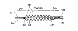
- this invention is a manufacturing method of the said disposable diaper, Comprising: The manufacturing process of the said expansion
- the panel manufacturing process includes 1) a step of fixing a plurality of elastic members in a stretched state by pulling each elastic member in one direction, and fixing the bonded portion to the bonded portion of the panel material provided in advance, to obtain a composite; 2) A contraction step of releasing the extended state of the plurality of elastic members in the composite and contracting each of the elastic members, and in the composite before releasing the extended state, the panel material
- the left and right side portions along the direction orthogonal to the one direction and the center portion of the panel material sandwiched between the left and right side portions are provided with the adhesive portions, and the left and right side portion adhesive portions are Bonding part of the central part Remote adhesion is low, there is provided a method for manufacturing a disposable diaper (hereinafter, when referred
- a deployable type in which a stretchable side panel material that expands and contracts in the width direction of the absorbent main body is attached to a portion disposed on the wearer's back side when worn.
- This type of disposable diaper can be manufactured by adding the side panel material in a separate process from the absorbent main body and adding it to the absorbent main body. Waste generated from the material can be suppressed, which is excellent in terms of environment and cost.
- the abdomen protrudes forward and the dorsal side is recessed. Furthermore, below these portions, the heel portion protrudes rearward, the base portion of the leg extends sideways, and the width increases. Therefore, in the case of a disposable diaper having a side panel that expands and contracts uniformly as a whole, when the side panel is pulled and the diaper is attached, the diaper does not fit into a body shape having three-dimensional unevenness, There is a tendency for a gap to be formed in a slightly depressed portion around the waist.
- Patent Document 6 describes that the tensile stress at the time of elastic deformation of a part of the side panel in the extending direction is made weaker than the tensile stress at the time of elastic deformation in other parts by cutting the elastic member or the like. However, even if a plurality of regions having different tensile stresses at the time of elastic deformation are provided in the extending direction of the side panel, the problem that gaps are likely to occur around the waist of the back is not solved.
- Patent Document 1 describes an absorbent article having a stretchable region containing an elastomer that recovers slowly. However, Patent Document 1 does not describe any configuration that does not create a gap around the waist of the back.
- an object of the present invention is to provide a disposable diaper that is less likely to have a gap on the back side of the wearer and has excellent fit to the body.
- the present invention is a disposable diaper comprising an absorbent main body including an absorbent body and stretchable side panels extending from both side edges of the absorbent main body, and the side panel includes a plurality of side panels between two nonwoven fabrics.
- the elastic member of the book has a stretchable part that is spaced apart, and a tab having a fastening part is provided at the tip, and the stretchable part is in the crossing direction intersecting the extending direction of the side panel.
- the portion located in the area having the tab is a high elongation stress portion having a high elongation stress, and the portion located on the crotch part side in the same direction is extended more than the high elongation stress portion.
- the present invention provides a disposable diaper having a low elongation stress portion with low stress (hereinafter referred to as the fifth invention when referring to the fifth invention).
- a deployable type in which a stretchable side panel material that expands and contracts in the width direction of the absorbent main body is attached to a portion arranged on the wearer's back side when worn.
- Disposable diapers are known. When wearing this disposable diaper, pull the side panel made of side panel material by hand, and fasten the fastening material provided at the tip to the outer surface etc. of the part arranged on the abdomen side of the absorbent main body And fix.
- this stretchable side panel often comes into contact with the wearer's skin when the diaper is worn, it is desired that the stretchable side panel has high air permeability.
- a side panel material for forming a stretchable side panel a panel material using a stretchable film or a panel material using a so-called thread rubber is known.
- a device such as perforating a film has been devised (for example, see Patent Document 2).
- the perforated film is laminated with other sheets such as non-woven fabric, the moisture permeability and air permeability are likely to be lowered. easy.
- the present applicant has proposed a composite stretchable member having a stretchable part composed of two sheet materials and a plurality of elastic members arranged between the two sheet materials in Patent Document 4.
- This composite elastic member has a configuration in which sheets are joined at a large number of dispersed joints, and an elastic member is arranged so as not to pass through those joints and is joined to a sheet material only at both ends thereof. is doing. Since this composite stretchable member has excellent properties such as flexibility, it is also preferable to use it as a constituent material of the stretchable part of the disposable diaper. However, this composite stretchable member is used as a side panel material of the unfolded diaper described above. In such a case, when a strong tensile force is applied to the side panel, if the elastic member fixed at the end portion is removed, the stretchability of the entire region where the elastic member is disposed may be lost.
- an object of the present invention relates to providing a disposable diaper that is excellent in the breathability and fit of the side panel, and that does not impair the stretchability of the side panel even when a strong tensile force is applied.
- the present invention is a disposable diaper including an absorbent main body including an absorbent body and stretchable side panels extending from both side edges of the absorbent main body, and the side panel expands and contracts in the extending direction.
- a plurality of elastic members are arranged between the two nonwoven fabrics at intervals in the crossing direction of the extending direction, and the side panel
- a plurality of continuous joint portions are provided on the leading end side in the outgoing direction, and in each of the continuous joint portions, the plurality of elastic members are continuously arranged in the intersecting direction of the extending direction.
- a large number of fusion parts which are fixed between the two nonwoven fabrics via an adhesive, and are distributed between the two nonwoven fabrics between the base end of the side panel and the continuous joint portion.
- the elastic member It It has an intermediate stretch regions are arranged so as not al, there is provided a disposable diaper (hereinafter, the term sixth invention refers to the present invention).
- the fastening tape is fastened with the stretchable side panel stretched, a large pulling force may be applied near the joint of the fastening tape to the side panel during or during wearing. As a result, the fastening tape may be stretched or torn, or the fastening tape may peel from the side panel.
- the subject of the present invention relates to providing a disposable diaper which is difficult to stretch, tear, peel off, etc. on the fastening tape.
- the present invention is a disposable diaper including an absorbent body, and having an absorptive main body having an abdominal part, a crotch part, and a dorsal part, and side panels extending from both side edges of the absorbent main body in the dorsal part.
- the side panel has a stretchable part in which a plurality of elastic members are respectively disposed between two panel members so as to extend in the extending direction of the side panel, and the tip of the side panel Fastening tape is provided, and the fastening tape has a tape fixing portion fixed in a state of being overlapped with the side panel, and the side panel has the expansion and contraction at a lower adjacent portion of the tape fixing portion.
- the present invention provides a disposable diaper having a plurality of bags produced by contraction of the portion (hereinafter referred to as the seventh invention when referring to the seventh invention).
- an ear part formed from an extensible laminate is formed by joining a chassis including a top sheet, a back sheet, and an absorbent core disposed between the top sheet and the back sheet.
- the diaper made is described, and it is described that the engaging member is arranged on the ear portion.
- the engagement member disposed on the ear part is easily peeled off by the expansion and contraction of the ear part when worn.
- the corners of the engaging member may come into contact with the wearer's skin and damage the skin.
- the present invention relates to a stretchable waist in which a fastening tape in which a hook tape having a large number of engaging protrusions is fixed on a sheet substrate extends from both side edges of a back side portion of a rectangular absorbent main body including an absorbent body.
- the fixed first fixing portion and the second fixing portion to which the fastening tape and the stretchable waist panel are fixed do not overlap, and the lower end edge in the longitudinal direction of the absorbent main body in the first fixing portion
- the lower end edge in the longitudinal direction of the absorbent main body in the sheet base material coincides with the lower end edge in the longitudinal direction of the absorbent main body in the second fixing portion.
- the disposable diaper is located above the lower end edge in the longitudinal direction of the fixed part in the longitudinal direction of the absorbent main body and is separated from the lower end edge in the longitudinal direction of the sheet base material (hereinafter, referred to as “the disposable diaper”).
- the eighth invention refers to this invention).
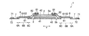
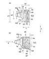
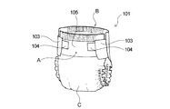
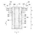
- FIG. 1 is a diagram showing an embodiment of the disposable diaper of the present invention, and is a plan view of the skin facing surface side (surface sheet side) schematically showing a state where the elastic members of the respective parts are extended and expanded in a planar shape.
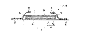
- FIG. 2 is a cross-sectional view schematically showing a cross section taken along the line II of FIG. 1, FIG. 16, and FIG. 29 (cross section of the crotch part in the body width direction).
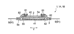
- 3 is a cross-sectional view schematically showing a cross section taken along line II-II in FIG. 1 (cross section in the body width direction of the back side portion).
- 4 is a cross-sectional view schematically showing a cross section taken along the line III-III of FIG. 1, FIG. 16, and FIG.
- FIG. 5 is a side view showing a state in which the fastening tape of the diaper shown in FIG. 1 is fixed to the fixing region.
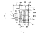
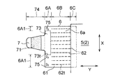
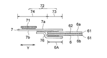
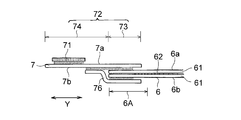
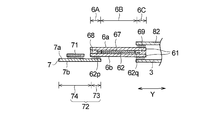
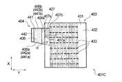
- FIG. 6 is an enlarged view of the main part (expandable panel and fastening tape) of the diaper shown in FIG. 1, and is a plan view on the skin facing surface side schematically illustrating a state in which the elastic member of each part is extended and expanded in a flat shape.
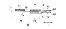
- FIG. 7 is a cross-sectional view schematically showing a cross section of a part of the main part shown in FIG. 6 in the main body width direction.
- 8 (a) and 8 (b) are enlarged views of the main part (expandable panel and fastening tape) of the diaper shown in FIG.
- FIG. 8 (a) is a plan view of the stretchable panel in its natural state.
- FIG. 8B is a plan view showing a state in which the stretchable panel is extended in the stretchable direction.
- FIG. 9 is an enlarged plan view showing a main part (expandable panel and fastening tape) of another embodiment of the disposable diaper of the present invention.
- FIG. 10 is an enlarged plan view showing a main part (expandable panel and fastening tape) of still another embodiment of the disposable diaper of the present invention.
- FIG. 11 is an enlarged plan view showing a main part (expandable panel and fastening tape) of still another embodiment of the disposable diaper of the present invention.
- FIG. 12 is an enlarged plan view showing a main part (expandable panel and fastening tape) of still another embodiment of the disposable diaper of the present invention.
- FIG. 13 is a top view which expands and shows the principal part (expandable panel and fastening tape) of further another embodiment of the disposable diaper of this invention.
- FIG. 14 is sectional drawing which shows typically the cross section of the main body width direction of the principal part (expandable panel and fastening tape) of further another embodiment of the disposable diaper of this invention.
- FIG. 15 is sectional drawing which shows typically the cross section of the main body width direction of the principal part (expandable panel and fastening tape) of further another embodiment of the disposable diaper of this invention.
- FIG. 13 is a top view which expands and shows the principal part (expandable panel and fastening tape) of further another embodiment of the disposable diaper of this invention.
- FIG. 14 is sectional drawing which shows typically the cross section of the main body width direction of the principal part (expandable panel and fast
- FIG. 16 is a figure which shows one Embodiment of the disposable diaper of this invention (2nd invention), The skin opposing surface side (surface sheet) which shows the state which extended the elastic member of each part and was expanded flatly
- FIG. 17 is a cross-sectional view schematically showing a cross section taken along the line II-II of FIG.
- FIG. 18 is a side view showing a state in which the fastening tape of the diaper shown in FIG. 16 is secured to the secured region.
- FIG. 19 is an enlarged view of a main part (expandable panel and fastening tape) of the diaper shown in FIG. 16, and schematically shows a state of the skin facing surface side in a state where the elastic member of each part is extended and expanded in a planar shape.
- FIG. 17 is a cross-sectional view schematically showing a cross section taken along the line II-II of FIG.
- FIG. 18 is a side view showing a state in which the fastening tape of the diaper shown in FIG. 16 is secured to the secured
- FIG. 20 is a cross-sectional view schematically showing a cross section in the main body width direction of a part of the main part shown in FIG. 21 (a) and 21 (b) are enlarged views of the main parts (the elastic panel and the fastening tape) of the diaper shown in FIG. 16, respectively.
- FIG. 21 (a) is a plan view of the natural state of the elastic panel.
- FIG. 21B is a plan view showing a state in which the stretchable panel is extended in the stretchable direction.
- FIG. 22 is an enlarged plan view showing a main part (expandable panel and fastening tape) of another embodiment of the disposable diaper of the present invention.
- FIG. 23 is an enlarged plan view showing a main part (expandable panel and fastening tape) of still another embodiment of the disposable diaper of the present invention.
- FIG. 24 is an enlarged plan view showing a main part (expandable panel and fastening tape) of still another embodiment of the disposable diaper of the present invention.
- FIG. 25 is an enlarged plan view showing a main part (expandable panel and fastening tape) of still another embodiment of the disposable diaper of the present invention.
- FIG. 26 is an enlarged plan view showing a main part (expandable panel and fastening tape) of still another embodiment of the disposable diaper of the present invention.
- FIG. 27 is a cross-sectional view schematically showing a cross section in the main body width direction of the main part (expandable panel and fastening tape) of still another embodiment of the disposable diaper of the present invention.
- FIG. 28 is a cross-sectional view schematically showing a cross section in the main body width direction of the main part (expandable panel and fastening tape) of still another embodiment of the disposable diaper of the present invention.
- FIG. 29 is a view showing an embodiment of the disposable diaper of the present invention (third invention), and schematically shows a skin facing surface side (surface sheet) in which the elastic members of the respective parts are extended and expanded in a planar shape.
- FIG. FIG. 30 is a cross-sectional view schematically showing a cross section taken along line II-II in FIG.
- FIG. 29 (cross section in the body width direction of the back side portion).
- FIG. 31 is a side view showing a state in which the fastening tape of the diaper shown in FIG. 29 is secured to the secured region.
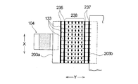
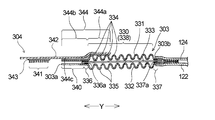
- FIG. 32 is an enlarged plan view schematically showing the stretchable panel of the diaper shown in FIG. 29 and the vicinity thereof.
- FIG. 33 is a cross-sectional view schematically showing a cross section in the body width direction of the stretchable panel shown in FIG. 32 and its vicinity.
- FIG. 34 is a plan view schematically showing, in an enlarged manner, the stretchable panel and the vicinity thereof according to another embodiment of the disposable diaper of the present invention (third invention).
- FIG. 35 is a cross-sectional view schematically showing a cross section of the stretchable panel shown in FIG.
- FIG. 36 is an enlarged plan view schematically showing an expandable panel and the vicinity thereof in still another embodiment of the disposable diaper of the present invention (third invention).
- FIG. 37 is sectional drawing which shows typically the cross section of the main body width direction of the expansion-contraction panel of further another embodiment of the disposable diaper of this invention (3rd invention), and its vicinity.
- 38 (a) to 38 (d) are schematic views of a part of the manufacturing process of the diaper shown in FIG. 29 (manufacturing process of the stretchable panel), respectively.
- 39 (a) to 39 (d) are schematic views of a part of the manufacturing process of a conventional disposable diaper (manufacturing process of the stretchable panel), respectively.
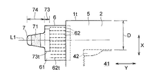
- FIG. 40 is a developed plan view of the disposable diaper according to the first embodiment of the present invention (the fifth invention) as viewed from the surface sheet side.
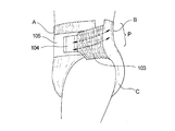
- FIG. 41 is a perspective view showing a wearing state of the disposable diaper shown in FIG. 40.
- FIG. 42 is an enlarged plan view showing the side panel of the disposable diaper shown in FIG. 40 and the vicinity thereof. 43 is an end view (contracted state) taken along the line IV-IV in FIG.
- FIG. 44 is a schematic view of the diaper wearing state of FIG. 40 viewed from the side.
- FIG. 45 is an enlarged plan view (corresponding to FIG. 42) showing the side panel and the vicinity thereof in the second embodiment of the present invention (fifth invention).
- FIG. 46 is an enlarged plan view (corresponding to FIG.
- FIG. 47 is a developed plan view of the disposable diaper according to the first embodiment of the present invention (sixth invention) as viewed from the surface sheet side.
- FIG. 48 is a perspective view showing a wearing state of the disposable diaper shown in FIG. 47.
- FIG. 49 is an enlarged plan view showing the side panel of the disposable diaper shown in FIG. 47 and the vicinity thereof.
- FIG. 50 is an end view (contracted state) taken along the line IV-IV in FIG.
- FIG. 51 is an enlarged plan view (corresponding to FIG. 49) showing the side panel and the vicinity thereof in the second embodiment of the present invention (sixth invention).
- FIG. 52 is an enlarged plan view (corresponding to FIG.
- FIG. 53 shows a so-called rubber drop in the elastic member of the side panel by pulling the side panel in the diaper of the reference form in which the side panel has only one front end side continuous joining portion toward the front end side. It is a reference figure showing a state.
- FIG. 54 is a developed plan view of the disposable diaper according to the first embodiment of the present invention (seventh invention) as viewed from the surface sheet side.
- FIG. 55 is an enlarged plan view (contracted state) of the side panel and the vicinity thereof in the first embodiment as viewed from the diaper outer surface side.
- 56 is a cross-sectional view (contracted state) taken along line III-III in FIG.
- FIG. 57 is a cross-sectional view (contracted state) taken along the line IV-IV in FIG.
- FIG. 58 is a plan view (elongated state) showing the side panel used in the disposable diaper shown in FIG. 54 in a single state.
- FIG. 59 is a side view of the wearing state of the disposable diaper shown in FIG. 54.
- FIG. 60 is an explanatory diagram showing one step in the method of manufacturing the disposable diaper shown in FIG.
- FIG. 61 is an enlarged plan view (corresponding to FIG. 55) of the side panel and its vicinity according to the second embodiment of the present invention (seventh invention) as viewed from the outer surface side of the diaper.
- 62 is a cross-sectional view (contracted state) taken along line VIII-VIII in FIG. FIG.
- FIG. 63 is a plan view (extended state) showing the side panel used in the third and fourth embodiments of the present invention (seventh invention) in a single state.
- FIG. 64 is the top view which looked at the state which expand
- FIG. 65 is an enlarged plan view of a stretchable waist panel provided in the unfolded disposable diaper of FIG. 66 is an enlarged plan view showing a state of the stretchable waist panel when the unfolded disposable diaper of FIG. 64 is worn.
- FIG. 67 is an enlarged plan view of the stretchable waist panel of the unfolded disposable diaper according to the second embodiment of the present invention (eighth invention) (corresponding to FIG. 65).
- FIG. 68 is an enlarged plan view of the stretchable waist panel of the unfolded disposable diaper according to the third embodiment of the present invention (eighth invention) (corresponding to FIG. 65).
- FIG. 69 is an enlarged plan view of a stretchable waist panel having a deployable disposable diaper according to a fourth embodiment of the present invention (eighth invention) (corresponding to FIG. 65).
- FIG. 70 is an enlarged plan view of the stretchable waist panel of the disposable diaper of Reference Example 1 of the eighth invention (corresponding to FIG. 65).
- FIG. 71 is an enlarged plan view of a stretchable waist panel included in the disposable diaper of Reference Example 2 of the eighth invention (corresponding to FIG. 65).
- FIG. 72 is an enlarged plan view of a stretchable waist panel having a disposable diaper of Reference Example 3 of the eighth invention (corresponding to FIG. 65).
- FIG. 73 is an enlarged plan view of the stretchable waist panel of the disposable diaper of Reference Example 4 of the eighth invention (corresponding to FIG. 65).
- FIG. 74 is an enlarged plan view of the stretchable waist panel of the disposable diaper of Reference Example 5 of the eighth invention (corresponding to FIG. 65).
- a disposable diaper 1 is a so-called unfolded panel-type disposable diaper.
- a liquid-permeable top sheet 2 a liquid-impermeable or water-repellent material.
- the top sheet 2 forms the skin facing surface 5 a of the absorbent main body 5, and the back sheet 3 forms the non-skin facing surface 5 b of the absorbent main body 5.
- Each of the top sheet 2 and the back sheet 3 has a rectangular shape and is wider and longer than the absorber 4.
- the top sheet 2 is narrower than the back sheet 3.
- a fastening tape 7 having a fastening portion 71 is provided on the outer edge 6A along the main body longitudinal direction X of each of the pair of stretchable panels 6 and 6, and the disposable diaper 1 is fastened as shown in FIG.
- the fastening portion 71 of the tape 7 is fastened to the non-skin facing surface 5b of the absorbent main body 5 and attached to the wearer.
- a skin opposing surface is a surface turned to a wearer's skin side at the time of wear in a disposable diaper and its structural member
- a non-skin opposing surface is a wearer at the time of wearing in a disposable diaper and its structural member. It is the surface that faces the other side of the skin.
- a longitudinal direction is a direction along the long side of a disposable diaper or its component member
- a width direction is a direction orthogonal to this longitudinal direction.
- the direction indicated by reference sign X in the figure is the longitudinal direction of the absorbent main body 5 (main body longitudinal direction)
- the direction indicated by reference sign Y is the width direction of the absorbent main body 5 (main body width direction).
- the disposable diaper 1 includes an abdominal part A and a dorsal part B, and a crotch C positioned between these A and B.
- the ventral side A is a part located on the stomach side of the diaper wearer
- the back side B is the part located on the back side of the diaper wearer (part having a pair of stretchable panels 6 and 6)
- the crotch part C is It is a part located in the crotch of the wearer of a diaper.
- the abdominal part A, the crotch part C, and the dorsal part B are each when the disposable diaper 1 (absorbent main body 5) is divided into three regions so that the entire length in the main body longitudinal direction X is divided into three equal parts. Corresponds to the area.
- the absorber 4 includes a liquid-retaining absorbent core 41 and a liquid-permeable core wrap sheet 42 that wraps the absorbent core 41.
- the absorbent core 41 has a long shape in the same direction as the absorbent main body 5 (direction directed to the wearer's front-rear direction when worn), and the central portion of the main body longitudinal direction X is confined. Yes.
- the absorbent core 41 is sandwiched between two upper and lower core wrap sheets 42, and the entire areas of the skin facing surface side and the non-skin facing surface side are covered with the core wrap sheet 42.
- the absorbent core 41 and the core wrap sheet 42 may be joined to each other at a predetermined site by an adhesive such as a hot melt adhesive.
- the absorbent main body 5 has an absorbent core non-arranged region D in which the absorbent core 41 is not disposed on at least one end side in the main body longitudinal direction X. More specifically, the total length in the main body longitudinal direction X of the absorbent core 4 is shorter than the total length in the main body longitudinal direction X of the absorbent main body 5, and the absorbent core 4 has the absorption core as shown in FIG.
- the absorbent core non-arrangement region D is formed in each of the abdominal side A and the back side B of the absorbent main body 5 by being disposed in the central portion of the main body longitudinal direction X.
- Absorbent core non-arrangement area D is a part located in a waist part of a wearer of a diaper, and it is a main part length from a waist edge (longitudinal edge) 1t of diaper 1 in back side part A and abdominal side part B, respectively. It is a region having a length of about 10% of the entire length of the main body longitudinal direction X of the diaper 1 inward in the direction X.
- the absorbent core non-arrangement region D in the present embodiment includes the top sheet 2 and the back sheet 3 and may further include the core wrap sheet 42.
- Each side part along the body longitudinal direction X of the absorbent main body 5 is provided with a side sheet 82 to which an elastic member 81 is fixed in an extended state on one side edge part.
- a pair of three-dimensional gathers are formed.
- the left and right leg portions arranged around the wearer's legs are provided with elastic members 83 along the longitudinal direction X of the main body, and the leg portions when worn are contracted by the elastic members 83.
- a pair of leg gathers is formed.
- the pair of side sheets 82 and 82, the top sheet 2, the absorber 4, the elastic members 81 and 83, and the back sheet 3 are integrated by a known joining means such as a hot-melt adhesive.
- the absorbent main body 5 is configured. As shown in FIGS.
- the side seats 82 (three-dimensional gathers) are disposed at the both ends of the three-dimensional gathers in the longitudinal direction X of the three-dimensional gathers at the back side portion A and the ventral side portion B. Is fixed to the surface sheet 2 via an adhesive at the tip portion when the erection stands.
- the adhesive that fixes the side sheet 82 to the top sheet 2 is coated in a straight line extending in the main body longitudinal direction X.
- part with the surface sheet 2 of the side sheet 82 is good also not only the arrangement
- a non-skin facing surface 5 b of the absorbent main body 5 in the abdominal side A of the disposable diaper 1 has an attachment region 55 made of a female member of a mechanical hook-and-loop fastener. Is formed.
- the to-be-attached area 55 is formed by bonding and fixing a female member of a mechanical surface fastener to the non-skin facing surface of the back sheet 3 with a known bonding means (for example, an adhesive or heat seal).
- the fastening part 71 of the fastening tape 7 which consists of a male member of a surface fastener can be detachably fastened.
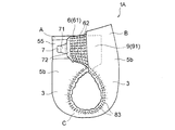
- the abdominal side flaps 9 and 9 are formed in the both-sides edge along the main body longitudinal direction X of the absorptive main body 5 in the abdominal side part A of the disposable diaper 1.
- FIG. The ventral flap 9 is made of a non-stretchable sheet material 91, and the sheet material 91 has an inner edge (side edge near the absorbent main body 5) along the longitudinal direction X of the main body.
- the sheet 3 is fixed by a known joining means such as a hot-melt adhesive.
- each of the pair of stretchable panels 6 and 6 has a body width inwardly in the body width direction Y from the outer edge 6A to which the fastening tape 7 (tape base end 73) is fixed. It has a stretchable part 6B having stretchability in the direction Y. More specifically, the stretchable panel 6 has an outer edge portion 6A and an inner edge portion 6C located on the opposite side of the body width direction Y from the outer edge portion 6A, and these both side edge portions 6A and 6C. An elastic part 6B is provided between them. As shown in FIG. 3, the inner edge 6 ⁇ / b> C of the stretchable panel 6 is fixed between the side sheet 82 and the back sheet 3 by a known joining means such as a hot-melt adhesive.
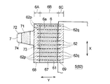
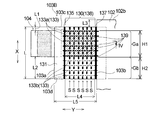
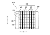
- the stretchable panel 6 (stretchable part 6B) includes a panel member 61 having a rectangular shape (rectangular shape) in plan view, and a plurality of elastic members 62 that are fixed to the panel member 61 in an extended state and extend in the body width direction Y.
- the plurality of elastic members 62 are arranged on the panel member 61 at a predetermined interval in the main body longitudinal direction X. More specifically, the stretchable panel 6 (stretchable part 6B) has a plurality of thread-like elastic members 62 extending in the body width direction Y between the two opposing panel members 61, 61 in the body longitudinal direction X.
- the two panel members 61, 61 that are opposed to each other and are arranged at a predetermined interval are arranged on a plurality of linear joints 63 that extend in the longitudinal direction X of the main body, as shown in FIG. 6. Are joined.
- the plurality of joints 63 are arranged at a predetermined interval in the main body width direction Y.
- Each joint 63 is formed by applying a known adhesive such as a hot-melt adhesive, is continuous over the entire length of the main body longitudinal direction X of the panel material 61, and the expansion / contraction direction Y of the elastic member 62 is A continuous linear joining line is formed along the orthogonal direction.
- Each of the plurality of elastic members 62 extends from the outer edge of the expansion / contraction part 6B to the inner edge over at least the entire length in the body width direction Y of the expansion / contraction part 6B. It overlaps and is being fixed to the inner surface of the panel material 61 by each this junction part 63.
- the stretchable part 6B in the present embodiment is a joint located closest to the absorbent main body 5 in the body width direction Y among the plurality of joints 63 arranged on the stretchable panel 6 (panel material 61). This is a portion sandwiched between the portion 63a and the joint portion 63b located farthest from the main body width direction Y (farthest from the absorbent main body 5).
- the outer edge portion 6A in the present embodiment is a region located on the outer side of the main body width direction Y with respect to the joint portion 63b in the stretchable panel 6.
- the outer edge portion 6 ⁇ / b> A is a non-stretchable region that does not have the elastic member 62 fixed in the stretched state and does not substantially have stretchability in the main body width direction Y unlike the stretchable portion B.
- the adhesive is not used for joining the structural members of the stretchable panel 6.
- “The adhesive joint is not present in the non-stretchable region” means that in the non-stretchable region, the components of the stretchable panel 6 (panel material 61) are joined to each other (other than the components of the stretchable panel 6). This means that the application amount of the adhesive used in the case where the constituent members are directly joined to each other without the intervening member is 0 g / m 2 .
- the adhesive joint portion that is not present in the non-stretchable region here joins the constituent members (panel material 61) of the stretchable panel 6 (directly without interposing other members).
- An adhesive joint that joins the constituent members of the stretchable panel 6 and other members for example, an adhesive joint that joins the panel material 61 and the tape base 72 is not included. Therefore, in the non-stretchable region, there may be an adhesive joint where the constituent members of the stretchable panel 6 and other members are joined by an adhesive.
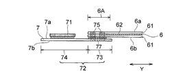
- the tape base material 72 is fixed to the panel material 61 by fusion (fusing portion 75) and an adhesive (adhesive bonding portion 77).
- a known adhesive such as a hot melt adhesive may be used, or other than the adhesive Joining means, for example, fusion such as heat sealing, may be used, or an adhesive and other joining means other than the adhesive may be used in combination.
- the non-stretchable region (outer edge portion 6A) of the stretchable panel 6 located outside the stretchable portion 6B in the main body width direction Y is a component of the stretchable panel 6 (panel material).
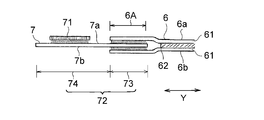
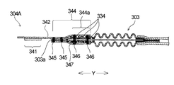
- Fastening tape 7 is configured to include a tape base 72 having a fastening portion 71 as shown in FIGS. 3, 6 and 7.
- the tape base 72 is connected to the tape base end 73 and fixed to the outer edge 6A of the stretchable panel 6, and projects outward from the outer edge 6A in the body width direction Y and is fastened. It has the tape front-end
- the fastening portion 71 is made of a male member of a mechanical surface fastener, and is provided on one side (skin-facing surface) of the tape front end portion 74.
- the above-described secured region 55 made of a female member of a mechanical surface fastener. It can be detachably fastened to.
- the fastening tape 7 is fixed to the non-skin facing surface 6b of the outer edge 6A of the stretchable panel 6 by a tape base end 73 as shown in FIGS.
- the tape base end portion 73 is fixed to the outer edge portion 6A of the stretchable panel 6 by a joining means including fusion, specifically, fusion and adhesive, and the tape base end portion 73 and the stretchable panel 6 (panel In the region where the material 61) overlaps (the tape fixing region of the outer edge portion 6A (non-stretchable region)), as shown in FIGS.
- a plurality of shaped fused portions 75 are formed.
- the outer edge portion 6A is a part of the aforementioned non-stretchable region, and as described above, the adhesive is used to join the constituent members (panel material 61) of the stretchable panel 6 in the non-stretchable region (outer edge portion 6A).
- an adhesive and / or other joining means other than the adhesive may be used as a joining means between the constituent member of the stretchable panel 6 and another member (tape base material 72).
- fusion such as heat sealing
- a combination of fusion and adhesive is employed as the joining means in this embodiment.
- Fusion here is a method in which one or more of a plurality of members (in this embodiment, two panel members 61 and a tape base end portion 73) are heated and melted to join the plurality of members together.
- a known heat sealing method, ultrasonic sealing method, high frequency sealing method and the like can be mentioned.
- the fused portion 75 in the present embodiment is formed by a known heat seal method.
- the heat seal for forming the fused portion 75 may be performed from the skin facing surface 6a side of the outer edge portion 6A (panel material 61) or from the non-skin facing surface 6b side.
- the plurality of fused portions 75 are arranged at predetermined intervals in both the main body longitudinal direction X and the main body width direction Y.
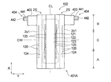
- the tape base end portion 73 has a rectangular shape in plan view, and has an outer end 73 s and an inner end 73 t along the main body width direction Y.
- the outer end 73s and the inner end 73t constitute a pair of short sides of the rectangular tape base end portion 73, and the inner end 73t is located inward in the main body longitudinal direction X relative to the outer end 73s, and In particular, it is close to the crotch C.
- this inner side edge 73t is arrange
- the elastic member (hereinafter also referred to as the innermost elastic member) 62t is located outward (upward in FIG. 6) in the longitudinal direction X of the main body.
- the innermost elastic member 62t is placed with the innermost elastic member 62t in the main body longitudinal direction X and is located inward (lower in FIG. 6) in the main body longitudinal direction X, the expansion and contraction described later is performed. The expansion / contraction characteristics of the panel 6 cannot be obtained.
- the inner end 73t of the tape base end portion 73 which is a fixing portion of the fastening tape 7 to the stretchable panel 6, is the innermost elastic member of the stretchable panel 6. It is located outside the main body longitudinal direction X from 62t, and, as described above, 2) the tape base end portion 73 is fixed to the outer side in the main body width direction Y from the stretchable portion 6B.
- the non-stretchable region (outer edge portion 6A) of the stretchable panel 6 there is no adhesive as a joining means between the constituent members (panel material 61) of the stretchable panel 6, and therefore the non-stretchable region Fastening when the disposable diaper 1 is worn by adopting the two points that the tape non-fixed area (area that does not overlap with the tape base end 73 in the non-stretchable area) is secured.
- FIG. 8A shows a natural state of the stretchable panel 6 (a state where no external force is applied), and FIG. 8B shows a state where the stretchable panel 6 is stretched in the stretchable direction Y.
- the elastic member 62 contracts starting from the outermost joints 62a and 62b of the elastic member 62, and as shown in FIG.
- a plurality of ridges 65 extending in a direction (main body longitudinal direction) X orthogonal to the main body width direction) Y are formed.
- Each flange 65 is formed between adjacent joints 63, 63 (not shown in FIG. 8, see FIG. 6).
- Each ridge 65 is formed so as to protrude from both the skin facing surface 6a and the non-skin facing surface 6b of the stretchable panel 6, and the tip of each ridge 65 in the protruding direction has a convex curved surface having a circular arc cross section. Forming.
- the fastening portion 71 of the fastening tape 7 is fastened to the fastened region 55.
- the tip of the fastening tape 7 is picked with a finger and pulled straight, and when the external force (tensile force) F is applied to the expansion / contraction panel 6 along the expansion / contraction direction Y as shown in FIG.
- Part of the stretchable part 6B located between the tape base end 73 and the absorbent main body 5 in the stretchable panel 6 due to the stretchability of the stretchable panel 6 due to the adoption of the two points 1) and 2) (Hereinafter also referred to as a tape base end adjacent portion) is caused by the external force (tensile force) F of the fastening tape 7 being directly transmitted to the outermost joint portion 62a of the elastic member 62 adjacent to the tape base end portion.
- the outermost joint The elastic member 62 becomes the extended length w6 (see FIG. 8B) without being twisted starting from 62a.
- a fastening tape is provided on a portion (lower part of the stretchable panel 6) located inward of the main body longitudinal direction X (lower in FIG.
- the elastic members 62 and 62t are located inward in the longitudinal direction X of the main body from the inner end 73t of the tape proximal end 73.
- the overlapping elastic member 62 is less likely to be pulled by the external force F accompanying the tension of the fastening tape 7, and the degree of expansion is larger than that of the elastic member 62 overlapping the outermost joint 62a. Therefore, the lower portion of the stretchable panel 6 located inward of the main body longitudinal direction X from the inner end 73t (the outermost joining portion 62b exists) is relatively elongated as compared with the tape base end adjacent portion.
- the lengths w6 ′ and w6 ′′ after extension of the two elastic members 62 at the lower part of the stretchable panel 6 are smaller than the length w6 after stretch of the stretchable part 6B adjacent to the tape base end part, The extension amount of the lower part of the elastic panel 6 is reduced.
- the portion corresponding to the lower portion of the elastic panel 6 described above is Although the peripheral length increases because it hits the bulge of the buttocks and the base of the leg, as described above, the expansion panel 6 has a margin for expansion more than the tape base end portion 73 because the lower part of the expansion panel 6 is in a weakly expanded state.
- the fastening force to the leg periphery of the lower part of the expansion-contraction panel 6 located around a wearer's leg is reduced, and it becomes difficult to attach
- the extended length w6 of the expansion / contraction portion 6B adjacent to the tape base end portion is longer than the extended length w6 ′ of the elastic member 62 below the expansion / contraction panel 6.
- W6 " the contraction force of the tape proximal end adjacent portion is increased, whereby the back end portion (absorbent core) of the disposable diaper 1 located at the waist portion of the wearer's back side. Since the tensile force F is directly transmitted to the non-arranged region D), a gap is less likely to be generated between the wearer's back and the dorsal end during wearing of the disposable diaper 1, and fit and leakage prevention Improves.
- the tape base end portion 73 is fixed to the stretchable panel 6 by the fused portion 75 and the adhesive joint portion 77, so that the fastening tape 7 is pulled during the fastening operation.
- the inconvenience of the fastening tape 7 coming off is avoided, and the rigidity of the tape base end portion 73 is improved by the use of an adhesive and the formation of the fused portion 75. Therefore, even if the fastening tape 7 is pulled, the tape base The end 73 is less likely to be twisted, the difference in tensile force between the tape base end 73 and the lower part of the above-described stretchable panel 6 is increased, and the lower part tends to be in a weakly stretched state, and the effects described above are further achieved. It becomes easy.
- the length w1 (see FIG. 8A) of the stretchable panel 6 in the body longitudinal direction X in the natural state is preferably 50 to 120 mm, and more preferably 60 to 100 mm.
- the length w2 (see FIG. 8 (a)) of the part (outer edge part 6A and the elastic part 6B) of the elastic panel 6 in the natural state extending outward from the absorbent main body 5 in the main body width direction Y is The thickness is preferably 20 to 60 mm, more preferably 25 to 50 mm.
- the length w3 of the tape base end portion 73 in the main body longitudinal direction X is preferably 20 to 100 mm, more preferably 30 to 60 mm.
- the length w4 of the tape base end portion 73 in the body width direction Y is preferably 8 to 20 mm, more preferably 10 to 18 mm.
- the interval w5 (see FIG. 8A) between the adjacent elastic members 62 and 62 is preferably 3 to 15 mm, more preferably 5 to 10 mm.
- the number of the elastic members 62 disposed between the inner end 73t of the tape base end portion 73 and the innermost elastic member 62t is preferably 1 to 15, more preferably 3 to 10.
- top sheet 2 and back sheet 3 various kinds conventionally used in the technical field concerned can be used.
- surface sheet 2 various liquid-permeable sheet materials such as a nonwoven fabric and an apertured film can be used.
- back sheet 3 various liquid impervious materials such as a resin film having no moisture permeability, a resin film having fine pores and moisture permeability, a nonwoven fabric such as a water-repellent nonwoven fabric, and a laminate of these and other sheets.
- water repellent materials can be used.
- the absorbent core 41 constituting the absorbent body 4 a liquid-retaining material conventionally used in the technical field can be used without any particular limitation.
- fibers made of hydrophilic fibers such as wood pulp An aggregate, a fiber aggregate in which particulate water-absorbing resin is held, or the like can be used.
- seat 42 which comprises the absorber 4 liquid permeable sheets, such as paper, a nonwoven fabric, an apertured film, can be used, for example.
- seat 82 the thing similar to the back surface sheet 3 can be used.
- Examples of the panel material 61 constituting the stretchable panel 6 include non-woven fabrics, woven fabrics, knitted fabrics, paper, resin films, and the like by various manufacturing methods such as air-through nonwoven fabric, heat roll nonwoven fabric, spunlace nonwoven fabric, spunbond nonwoven fabric, and meltblown nonwoven fabric. , And a sheet material obtained by laminating and integrating these two or more can be used.
- the tape base material 72 which comprises the fastening tape 7 a laminated body of a nonwoven fabric, a nonwoven fabric, and a resin film etc. can be used, for example.
- the stretchable panel and the fastening tape according to the present invention are not limited to the above-described embodiments, and various forms can be adopted without departing from the spirit of the present invention.
- constituent parts different from the above-described embodiments are mainly described, and the same constituent parts are denoted by the same reference numerals, and the description thereof is omitted.
- the description of the above embodiment is applied as appropriate to components that are not particularly described.
- the two panel members 61, 61 of 6A1 are fused together, and the tape base end portion 73 and the expansion panel 6 are fixed to the tape base end non-fixed region 6A1.
- a plurality of elliptical fusion parts 75 are formed in plan view, similar to the fusion part (not shown in FIG. 9). According to the embodiment shown in FIG.
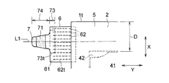
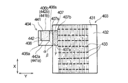
- the imaginary straight line L1 that bisects the tape tip 74 in the body longitudinal direction X is more outward in the body longitudinal direction X than the imaginary straight line L2 that bisects the stretchable panel 6 in the body longitudinal direction X (see FIG. In FIG. 10, it is located at the upper side), that is, at a position far from the crotch C.
- the embodiment shown in FIG. 10 adjusts the positional relationship between the virtual straight line L1 passing through the center of the fastening tape 7 and the virtual straight line L2 passing through the center of the stretchable panel 6 to thereby adjust the inner end 73t of the tape base end 73.
- the distance w7 between the virtual straight line L1 and the virtual straight line L2 is preferably 5 to 25 mm, more preferably 8 to 20 mm.
- a gap is less likely to occur between the wearer's back and the back side end of the diaper 1, and the absorbent core is excreted liquid such as urine. Even when the liquid is absorbed and expanded, the gap is less likely to occur.
- the length (width of the tape front end portion 74) w8 of the main body longitudinal direction X of the tape front end portion 74 is the length of the tape base end portion 73 in the main body longitudinal direction X (tape base end portion).
- the width of 34) is equal to or shorter than w3.
- the “length in the longitudinal direction of the main body of the tape front end” means the maximum length when the length is not constant, and the same applies to the “length in the longitudinal direction of the main body of the tape base end”. is there.
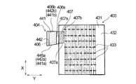
- the fastening tape 7A shown in FIG. 12 has a rectangular shape in plan view, and the length (width) in the longitudinal direction X of the main body 73 and 74 is the same. According to the embodiment shown in FIG.
- the tape base end portion 73 is wider than the tape front end portion 74.
- the tape base end portion 73 is the same width as the tape front end portion 74.
- the distance between the inner end 73t of the tape base end 73 and the inner end 6t of the stretchable panel 6 can be made relatively longer than that of the fastening tape 7,
- the tension force around the wearer's leg and the tension force on the back waist portion The difference is further increased, and the occurrence of the above-described weakly stretched state of the lower portion of the stretchable panel 6 is promoted.
- the length w8 of the tape front end portion 74 in the longitudinal direction X of the main body is the same as the half of the length of the stretchable panel 6 in the longitudinal direction of the body X (the width of the stretchable panel 6) w1.
- the “length in the longitudinal direction of the expansion panel” means the maximum length when the length is not constant.
- the length w8 of the tape front end portion 74 is equal to or shorter than half the length w1 of the stretchable panel 6 as shown in FIG. 6 and the like as well as the fastening tape 7A shown in FIG. It can also be applied to the fastening tape 7 (a fastening tape in which the tape base end portion 73 is wider than the tape leading end portion 74).
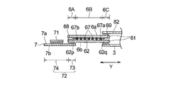
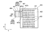
- the embodiment shown in FIG. 13 differs from the previous embodiment in the stretchable panel. That is, in the stretchable panel 6 shown in FIG. 6, the plurality of elastic members 62 are a plurality of continuous linear joints extending in the longitudinal direction X of the main body at the inner edge 6C and the stretchable part 6B of the stretchable panel 6, respectively. 63, and is fixed to the panel material 61 at each joint 63. However, in the stretchable panel 6P shown in FIG. The plurality of elastic members 62 are not fixed to the panel material 61 except for the other end side (the portion where the joint portion 63b exists). That is, in the stretchable part 6B of the stretchable panel 6P shown in FIG.
- the joint part 63a located closest to the inner body width direction Y (closest to the absorbent main body 5) and the outermost part in the body width direction Y are located.
- the plurality of joint portions 66 arranged in the region sandwiched between the joint portions 63b (the furthest from the absorbent main body 5) are respectively formed into a plurality of rectangular small joint portions 66s in plan view in the body longitudinal direction X.
- the plurality of elastic members 62 are not overlapped with the small joints 66a with respect to the plurality of broken joints 66, and the gaps between the small joints 66a and 66a adjacent in the longitudinal direction X of the main body. It arrange
- the elastic member 62 of the expansion / contraction part 6B is not joined to the panel material 61. It is possible to uniformly extend within the stretchable part 6B, and as a result, there is an effect that the marks around the legs are less likely to occur. Moreover, the fall of the moisture permeability of the panel material 61 by an adhesive agent and the increase in rigidity can be prevented.
- the stretchable panel 6P the composite stretchable member described in Patent Document 4 according to the previous application of the present applicant can be used.
- the fastening tape 7 is fixed to the skin facing surface 6 a of the outer edge portion 6 ⁇ / b> A of the stretchable panel 6 by the tape base end portion 73.
- a reinforcing member 76 that reinforces the fastening of the fastening tape 7 to the elastic panel 6 is provided on the non-skin opposing surface 7 b of the fastening tape 7 and the non-skin opposing surface 6 b of the elastic panel 6.
- the reinforcing member 76 for example, a nonwoven fabric or a resin film can be used.
- the tape base material 72 (tape base end portion 73) of the fastening tape 7 is sandwiched and fixed between the two panel materials 61, 61 facing each other constituting the stretchable panel 6. is doing.
- the reinforcing member 76 can also be applied to the embodiment shown in FIG. That is, in the embodiment shown in FIG. 7, the reinforcing member 76 is provided on the skin facing surface 7 a of the fastening tape 7 and the skin facing surface 6 a of the stretchable panel 6 rather than the fastening portion 71 in the tape leading end portion 74 of the fastening tape 7. It can be fixed so as to straddle the inner part in the width direction Y (the part sandwiched between the fastening part 71 and the panel member 61) and the outer edge part 6A.
- a disposable diaper 1A according to an embodiment of the present invention is a so-called unfolded panel-type disposable diaper.
- a top sheet 2 a liquid-impermeable or water-repellent (hereinafter collectively referred to as “liquid-impermeable”) back sheet 3, and a liquid-retaining absorbent 4 disposed between the two sheets 2 and 3.
- It has a longitudinally long absorbent main body 5 (long in one direction X) and a pair of elastic panels 6 and 6 fixed to both side edges along the main body longitudinal direction X of the absorbent main body 5.
- the top sheet 2 forms the skin facing surface 5 a of the absorbent main body 5, and the back sheet 3 forms the non-skin facing surface 5 b of the absorbent main body 5.
- Each of the top sheet 2 and the back sheet 3 has a rectangular shape and is wider and longer than the absorber 4.
- the top sheet 2 is narrower than the back sheet 3.
- a fastening tape 7 having a fastening portion 71 is provided on the outer edge 6A along the main body longitudinal direction X of each of the pair of stretchable panels 6 and 6, and the disposable diaper 1A is fastened as shown in FIG.
- the fastening portion 71 of the tape 7 is fastened to the non-skin facing surface 5b of the absorbent main body 5 and attached to the wearer.
- the disposable diaper 1A of the present embodiment will be described in more detail.
- the disposable diaper 1A includes an abdominal part A, a back part B, and a crotch part C positioned between these A and B.
- the ventral side A is a part located on the stomach side of the diaper wearer
- the back side B is the part located on the back side of the diaper wearer (part having a pair of stretchable panels 6 and 6)
- the crotch part C is It is a part located in the crotch of the wearer of a diaper.
- the abdominal part A, the crotch part C, and the dorsal part B are each when the disposable diaper 1A (absorbent main body 5) is divided into three regions so that the entire length in the main body longitudinal direction X is divided into three equal parts. Corresponds to the area.
- the disposable diaper 1 ⁇ / b> A of the present embodiment has the same structure as the absorbent main body 5 and the abdominal flap 9 in the disposable diaper 1 described above. And a ventral flap 9. Therefore, about the absorptive main body 5 and the abdominal side flap 9, the description about the disposable diaper 1 mentioned above (including a more preferable structure and a modification) is applied also to the disposable diaper 1A of this embodiment.
- each of the pair of stretchable panels 6, 6 is a rectangular (rectangular) panel material 61 in plan view, and a plurality of panels that are fixed to the panel material 61 and extend in the body width direction Y.
- the main body width direction Y includes an elastic part 6B that includes the elastic member 62 and has elasticity in the main body width direction Y, and a non-extension part 6A that does not have elasticity in the main body width direction Y.
- the outer edge portion 6A of the stretchable panel 6 to which the fastening tape 7 (tape base end portion 73) is fixed is non-stretchable, and the entire region is the non-stretchable portion 6A.
- the stretchable panel 6 will be further described.
- the stretchable panel 6 includes a non-stretchable outer edge portion 6A, and the outer edge portion 6A is located on the opposite side of the body width direction Y.
- the inner edge portion 6C is provided, and a stretchable elastic portion 6B is provided between the both side edge portions 6A, 6C.
- the stretchable panel 6 has an inner edge 6 ⁇ / b> C along the body longitudinal direction X fixed between the side sheet 82 and the back sheet 3 by a known joining means such as a hot-melt adhesive. ing.
- a known joining means such as a hot-melt adhesive.
- each of the pair of stretchable panels 6 and 6 is preferably fixed to the absorbent main body 5 at a portion where the elastic member 62 is not disposed in the inner edge portion 6C. That is, in a plan view as shown in FIG. 19, the elastic main body 5 and the panel material 61 are not present at the portion where the absorbent main body 5 and the stretchable panel 6 (inner edge portion 6C) overlap. This is preferable in terms of strengthening the adhesiveness.
- the plurality of elastic members 62 are arranged at a predetermined interval in the longitudinal direction X of the main body, are fixed to the panel material 61 in an expanded state by the expansion / contraction part 6B, and extend from the expansion / contraction part 6B to the non-extension / contraction part. (Outer edge) extends to 6A. More specifically, the stretchable panel 6 (stretchable part 6B) has a plurality of thread-like elastic members 62 extending in the main body width direction Y between the two opposing panel members 61, 61 in the main body longitudinal direction X. As shown in FIG.
- two panel members 61, 61 that are arranged to be intervened at a predetermined interval are connected to a plurality of linear joint portions 63 that extend in the longitudinal direction X of the main body.
- the plurality of joints 63 are arranged at a predetermined interval in the main body width direction Y.
- Each joint 63 is formed by applying a known adhesive such as a hot-melt adhesive, is continuous over the entire length of the main body longitudinal direction X of the panel material 61, and the expansion / contraction direction Y of the elastic member 62 is A continuous linear joining line is formed along the orthogonal direction.
- Each of the plurality of elastic members 62 reaches the inner edge side from the outer edge side of the elastic part 6B over the entire length of the elastic part 6B in the body width direction Y. Furthermore, the elastic part 6B and the non-elastic part It extends from the boundary with 6A to the non-stretchable portion 6A side and enters the non-stretchable portion 6A. That is, the non-expandable portion (outer edge portion) 6A of the stretchable panel 6 has one end portion of the elastic member 62 that crosses the stretchable portion 6B in the main body width direction Y as shown in FIG. In FIG. 19, for ease of explanation, the joint portion 63 is described so that it can be clearly recognized from the outside. However, this is not necessarily the case.
- the plurality of elastic members 62 overlap with the plurality of joints 63, respectively, and are fixed to the inner surface of the panel material 61 at the joints 63.
- the panel material 61 and the elastic member 62 are not joined, and the elastic member 62 in the outer edge portion 6A is not stretched (natural state). It is said that.
- the outer edge portion 6A is a non-stretchable portion 6A in which the panel material 61 and the elastic member 62 are not joined.
- the extension length of the elastic member 62 from the stretchable portion 6B to the non-stretchable portion (outer edge portion) 6A is the non-stretchable portion among the plurality of linear joint portions 63 in the stretchable portion 6B. It is longer than the interval between the two joints 63b, 63 closest to 6A. That is, as shown in FIG. 19, the length La of the elastic member 62 extending toward the non-stretchable portion 6 ⁇ / b> A is the outermost portion in the body width direction Y among the plurality of joint portions 63 arranged on the stretchable panel 6. This is longer than the distance Lb (see FIG.
- the part joined by the joining parts 63b and 63 in the elastic member 62 (part existing in the stretchable part 6B). Becomes a stretched state and a contraction force is generated in the part, and the contraction force exceeds the fixing force to the panel member 61 of the part by the joint portions 63b and 63, the elasticity corresponding to the extension length La.
- One end of the member 62 may move inward in the body width direction Y beyond the joint 63b due to the contraction of the part (so-called rubber removal occurs), and there is a possibility that the inconvenience of completely entering the expansion / contraction part 6B may occur.
- the extension length La is preferably 0.8-2.
- Each of the plurality of elastic members 62 may extend from the boundary between the expansion / contraction part 6B and the inner edge part 6C toward the inner edge part 6C and enter the inner edge part 6C.
- the other end of the elastic member 62 that crosses the stretchable part 6B in the body width direction Y may exist.
- the elastic member 62 (the other end portion of the elastic member 62) in the inner edge portion 6C is in a non-expanded state (natural state), similarly to the elastic member 62 (one end portion of the elastic member 62) in the outer edge portion 6A.
- the inner edge portion 6C is a non-stretchable portion 6C in which the panel material 61 and the elastic member 62 are not joined.
- the stretchable part 6B in the present embodiment is a joint located closest to the absorbent main body 5 in the body width direction Y among the plurality of joints 63 arranged on the stretchable panel 6 (panel material 61). This is a portion sandwiched between the portion 63a and the joint portion 63b located farthest from the main body width direction Y (farthest from the absorbent main body 5).
- the non-stretchable portion (outer edge portion) 6A in the present embodiment is a region located outside the main body width direction Y with respect to the joint portion 63b in the stretchable panel 6.
- the outer edge portion 6A is not in an expanded state like the stretchable portion B but has an end portion of the elastic member 62 in a natural state, and is substantially non-stretchable in the body width direction Y. 6A.
- one end of the plurality of elastic members 62 is present in a non-stretched state in the region located outside (non-stretchable portion 6A)
- the constituent members (panel material 61) of the stretchable panel 6 are joined by an adhesive. There is no adhesive joint portion, and no adhesive is used for joining the constituent members of the stretchable panel 6 in the non-stretchable portion 6A.
- the adhesive joint portion does not exist in the non-stretchable region” means that in the non-stretchable portion 6A, the constituent members (panel material 61) of the stretchable panel 6 are joined to each other (other than the constituent members of the stretchable panel 6). This means that the application amount of the adhesive used for bonding the constituent members directly without joining the members is 0 g / m 2 .
- the adhesive joint portion that is not present in the non-stretchable portion 6A here joins the constituent members (panel material 61) of the stretchable panel 6 to each other (directly without interposing other members).
- An adhesive joint that joins the constituent members of the stretchable panel 6 and other members for example, an adhesive joint that joins the panel material 61 and the tape base 72 is not included. Therefore, the non-stretchable portion 6A may include an adhesive joint portion in which the constituent members of the stretchable panel 6 and other members are joined by an adhesive.
- the tape base material 72 is fixed to the panel material 61 at the tape base end portion 73 by fusion (fusion portion 75) and an adhesive (adhesive bonding portion 77).
- the tape base end portion 73 is preferably fixed to the outer edge portion 6A of the stretchable panel 6 with an adhesive and a plurality of fused portions 75a.
- a known adhesive such as a hot-melt adhesive may be used, or other than the adhesive Joining means, for example, fusion such as heat sealing, may be used, or an adhesive and other joining means other than the adhesive may be used in combination.
- one end portion of the plurality of elastic members 62 is provided on the non-stretchable portion (outer edge portion) 6A of the stretchable panel 6 located outside the stretchable portion 6B in the body width direction Y.
- the non-stretchable portion (outer edge portion) 6A of the stretchable panel 6 located outside the stretchable portion 6B in the body width direction Y.
- the constituent members of the stretchable panel 6 (panel material 61)
- the non-stretchable portion 6A Definitive, fastening tape 7 regions (base tape 72) is attached difference in stiffness between the (region overlapping a tape base end portion 73, hereinafter also referred to as tape fixing area) is large.
- Fastening tape 7 includes a tape base material 72 having a fastening portion 71 as shown in FIGS. 17, 19, and 20.
- the tape base 72 is connected to the tape base end 73 and fixed to the outer edge 6A of the stretchable panel 6, and projects outward from the outer edge 6A in the body width direction Y and is fastened. It has the tape front-end
- the fastening portion 71 is made of a male member of a mechanical surface fastener, and is provided on one side (skin-facing surface) of the tape front end portion 74.
- the above-described secured region 55 made of a female member of a mechanical surface fastener. It can be detachably fastened to.
- the fastening tape 7 is fixed to the non-skin facing surface 6b of the outer edge portion (non-stretchable portion) 6A of the stretchable panel 6 by the tape base end portion 73 as shown in FIGS. Yes.
- the fastening tape 7 (tape base end portion 73) is fixed to the outer edge portion 6A of the stretchable panel 6 by a joining means including fusion, specifically, fusion and adhesive.
- a joining means including fusion, specifically, fusion and adhesive.
- a plurality of shaped fused portions 75 are formed.
- the non-stretchable portion (outer edge portion) 6A no adhesive is used for joining the constituent members (panel material 61) of the stretchable panel 6, but the constituent members of the stretchable panel 6 and other members (tape)
- an adhesive and / or other joining means other than the adhesive may be used.
- a combination of fusing and adhesive is employed as the joining means.
- Fusion here is a method in which one or more of a plurality of members (in this embodiment, two panel members 61 and a tape base end portion 73) are heated and melted to join the plurality of members together.
- the fused portion 75 in the present embodiment is formed by a known heat seal method.
- the heat seal for forming the fused portion 75 may be performed from the skin facing surface 6a side of the outer edge portion 6A (panel material 61) or from the non-skin facing surface 6b side.
- the plurality of fused portions 75 are arranged at predetermined intervals in both the main body longitudinal direction X and the main body width direction Y.
- the fused portion 75 is described so that it can be clearly recognized from the outside, but this is not always the case.
- FIGS. 16, 17, 18, and 21 to 28 showing the tape base end portion 73 other than FIGS. 19 and 20, the fused portion 75 is not shown for ease of explanation. ing.
- the tape base end portion 73 has a rectangular shape in plan view, and has an outer end 73 s and an inner end 73 t along the body width direction Y.
- the outer end 73s and the inner end 73t constitute a pair of short sides of the rectangular tape base end portion 73, and the inner end 73t is located inward in the main body longitudinal direction X relative to the outer end 73s, and In particular, it is close to the crotch C.
- this inner side edge 73t is arrange
- the plurality of elastic members 62 extend from the stretchable part 6B to the outer edge part (non-stretchable part) 6A, respectively, and 2) the outside The elastic member 62 at the edge 6A is in a non-extended state (natural state), and 3) the panel member 61 and the elastic member 62 are not joined at the outer edge 6A.
- the diaper 1 ⁇ / b> A is mounted, the mounting characteristics of the stretchable panel 6 when the fastening tape 7 is fixed to the fixed region 55 are formed.
- the outer edge 6 ⁇ / b> A of the stretch panel 6 has flexibility, and the elastic member 62 does not move even when the stretch panel 6 is stretched in the body width direction Y when mounted. Since it does not come off from the joint part 63b located on the outermost side in the width direction Y, the end part fixing of the elastic member 62 is made excellent in stability.
- the inner end 73t of the tape base end portion 73 which is a fixing portion of the fastening tape 7 to the elastic panel 6, is more than the innermost elastic member 62t of the elastic panel 6. Is located outside the main body longitudinal direction X, and, as described above, 5) located outside the main body width direction Y than the telescopic portion 6B and the tape base end 73 is fixed.
- the non-stretchable portion (outer edge portion) 6A of the stretchable panel 6 does not have an adhesive as a joining means between the constituent members (panel material 61) of the stretchable panel 6, and therefore, one of the non-stretchable portions 6A.
- FIG. 21A shows a natural state (a state where no external force is applied) of the stretchable panel 6, and FIG. 21B shows a state where the stretchable panel 6 is extended in the stretchable direction Y.
- the elastic member 62 contracts starting from the outermost joints 62a and 62b of the elastic member 62, and as shown in FIG.
- a plurality of ridges 65 extending in a direction (main body longitudinal direction) X orthogonal to the main body width direction) Y are formed.
- Each flange 65 is formed between adjacent joints 63 and 63 (not shown in FIG. 21; see FIG. 19).
- Each ridge 65 is formed so as to protrude from both the skin facing surface 6a and the non-skin facing surface 6b of the stretchable panel 6, and the tip of each ridge 65 in the protruding direction has a convex curved surface having a circular arc cross section. Forming.
- Part of the stretchable part 6B located between the tape base end 73 and the absorbent main body 5 in the stretchable panel 6 due to the stretchability of the stretchable panel 6 due to the adoption of the two points 4) and 5) (Hereinafter also referred to as a tape base end adjacent portion) is caused by the external force (tensile force) F of the fastening tape 7 being directly transmitted to the outermost joint portion 62a of the elastic member 62 adjacent to the tape base end portion.
- the outermost The elastic member 62 becomes the extended length w6 (see FIG. 21 (b)) without being twisted starting from the side joining portion 62a.
- a fastening tape is provided at a portion (lower part of the stretchable panel 6) located inward of the main body longitudinal direction X (downward in FIG. 21B) than the inner end 73 t of the tape base end 73 in the stretchable panel 6.
- 7 tape base end portion 73
- the outermost joint portion 62b of the elastic member 62 including 62t is pulled closer to the absorbent main body 5 side (back side portion B side) than the outermost joint portion 62a adjacent to the tape base end portion.
- FIG. 21 (b) the outer side in the width direction of the lower part of the expansion / contraction part 6B is twisted and is in a slightly extended state.
- the elastic members 62 and 62t are located inward in the longitudinal direction X of the main body from the inner end 73t of the tape proximal end 73.
- the overlapping elastic member 62 is less likely to be pulled by the external force F accompanying the tension of the fastening tape 7, and the degree of expansion is larger than that of the elastic member 62 overlapping the outermost joint 62a. Therefore, the lower portion of the stretchable panel 6 located inward of the main body longitudinal direction X from the inner end 73t (the outermost joining portion 62b exists) is relatively elongated as compared with the tape base end adjacent portion.
- the lengths w6 ′ and w6 ′′ after extension of the two elastic members 62 at the lower part of the stretchable panel 6 are smaller than the length w6 after stretch of the stretchable part 6B adjacent to the tape base end part, The extension amount of the lower part of the elastic panel 6 is reduced.
- the portion corresponding to the lower portion of the stretchable panel 6 described above is Although the perimeter length increases because it hits the bulge of the buttocks and the base of the leg, as described above, the lower part of the stretchable panel 6 is in a weakly stretched state, so that the stretchable panel 6 has a margin for extension than the tape base end 73.
- the fastening force to the leg periphery of the lower part of the expansion-contraction panel 6 located around a wearer's leg is reduced, and it becomes difficult to attach
- the extended length w6 of the elastic portion 6B adjacent to the tape base end portion is longer than the extended length w6 ′ of the elastic member 62 below the elastic panel 6.
- W6 " the contraction force of the tape proximal end adjacent portion is increased, and thereby the back end portion (absorbent core) of the disposable diaper 1A located at the waist portion on the wearer's back side. Since the tensile force F is directly transmitted to the non-arranged region D), it becomes difficult to create a gap between the wearer's back and the dorsal end during wearing of the disposable diaper 1A, and fit and leakage prevention Improve.
- the tape base end portion 73 is fixed to the stretchable panel 6 by the fused portion 75 and the adhesive joint portion 77, so that the fastening tape 7 is pulled during the fastening operation.
- the inconvenience of the fastening tape 7 coming off is avoided, and the rigidity of the tape base end portion 73 is improved by the use of an adhesive and the formation of the fused portion 75. Therefore, even if the fastening tape 7 is pulled, the tape base The end 73 is less likely to be twisted, the difference in tensile force between the tape base end 73 and the lower part of the above-described stretchable panel 6 is increased, and the lower part tends to be in a weakly stretched state, and the effects described above are further achieved. It becomes easy.
- the length w1 (see FIG. 21A) of the stretchable panel 6 in the body longitudinal direction X in the natural state is preferably 50 to 120 mm, and more preferably 60 to 100 mm.
- the length w2 (see FIG. 21 (a)) of the portion (outer edge 6A and stretchable portion 6B) of the stretchable panel 6 in the natural state extending outwardly from the absorbent main body 5 in the body width direction Y is The thickness is preferably 20 to 60 mm, more preferably 25 to 50 mm.
- the length w3 of the tape base end portion 73 in the main body longitudinal direction X is preferably 20 to 100 mm, and more preferably 30 to 60 mm.
- the length w4 of the tape base end portion 73 in the body width direction Y is preferably 8 to 20 mm, more preferably 10 to 18 mm.
- the interval w5 (see FIG. 21A) between the adjacent elastic members 62, 62 is preferably 3 to 15 mm, more preferably 5 to 10 mm.
- the number of the elastic members 62 disposed between the inner end 73t of the tape base end portion 73 and the innermost elastic member 62t is preferably 1 to 15, more preferably 3 to 10.
- the stretchable panel and the fastening tape according to the present invention are not limited to the disposable diaper 1A described above, and various forms can be employed without departing from the spirit of the present invention.
- a different component from 1A of disposable diapers of embodiment mentioned above is mainly explained, the same component attaches the same numerals, and explanation is omitted.
- the description of the above embodiment is applied as appropriate to components that are not particularly described.
- the two panel members 61, 61 are intermittently disposed in the tape non-fixed region of the outer edge (non-stretchable portion) 6 ⁇ / b> A of the stretchable panel 6. 75 are joined together. That is, an area in which the tape base end portion 73 is not fixed and includes two opposing panel members 61, 61 in the outer edge 6A of the stretchable panel 6 (the tape non-fixed area).
- the two panel members 61, 61 of 6A1 are intermittently fused to each other by the fusion part 75, and the fusion fixing the tape base end part 73 and the expansion panel 6 to the tape non-fixed region 6A1.
- a plurality of elliptical fusion parts 75 are formed intermittently as in the case of the attachment part (not shown in FIG. 22). According to the embodiment shown in FIG. 22, it is possible to prevent the panel material 61 constituting the tape non-fixed region 6 ⁇ / b> A ⁇ b> 1 from being peeled off or twisted without disturbing the above-described weakly extended state of the lower portion of the stretchable panel 6.
- the virtual straight line L1 that bisects the tape tip 74 in the main body longitudinal direction X is more outward in the main body longitudinal direction X than the virtual straight line L2 that bisects the telescopic panel 6 in the main body longitudinal direction X (see FIG. In FIG. 23, it is located at the upper side), that is, at a position far from the crotch C.
- the embodiment shown in FIG. 23 adjusts the positional relationship between the virtual straight line L1 passing through the center of the fastening tape 7 and the virtual straight line L2 passing through the center of the stretchable panel 6 to thereby adjust the inner end 73t of the tape base end 73.
- the distance w7 between the virtual straight line L1 and the virtual straight line L2 is preferably 5 to 25 mm, more preferably 8 to 20 mm.
- a gap is less likely to be generated between the wearer's back and the back side end of the diaper 1A, and the absorbent core is excreted liquid such as urine. Even when the liquid is absorbed and expanded, the gap is less likely to occur.
- the length (width of the tape front end portion 74) w8 of the main body longitudinal direction X of the tape front end portion 74 is the length of the tape base end portion 73 in the main body longitudinal direction X (tape base end portion).
- the width of 34) is equal to or shorter than w3.
- the “length in the longitudinal direction of the main body of the tape front end” means the maximum length when the length is not constant, and the same applies to the “length in the longitudinal direction of the main body of the tape base end”. is there.
- the fastening tape 7A shown in FIG. 25 has a rectangular shape in plan view, and the length (width) in the longitudinal direction X of the main body 73 and 74 is the same. According to the embodiment shown in FIG.
- the tape leading end portion 74 when an external force F is applied to the tape leading end portion 74 along the main body width direction Y and pulled, the external force F has the same width as that of the tape leading end portion 74. Since it is transmitted straight to the portion 73, it is difficult for the peripheral portion of the tape base end portion 73 of the stretchable panel 6 to be broken. Further, in the above-described fastening tape 7, the tape base end portion 73 is wider than the tape front end portion 74. However, in the fastening tape 7A shown in FIG. 25, the tape base end portion 73 is the same width as the tape front end portion 74.
- the distance between the inner end 73t of the tape base end portion 73 and the inner end 6t of the stretchable panel 6 can be made relatively longer than the fastening tape 7,
- the fastening tape 7A to the secured region 55 see FIGS. 16, 4 and 18
- the tensile force around the wearer's leg and the tensile force toward the waist on the back side The difference is further increased, and the occurrence of the above-described weakly stretched state of the lower portion of the stretchable panel 6 is promoted.
- the length w8 of the tape front end portion 74 in the main body longitudinal direction X is the same as or half the length of the main body longitudinal direction X of the stretchable panel 6 (width of the stretchable panel 6) w1.
- the “length in the longitudinal direction of the expansion panel” means the maximum length when the length is not constant.
- the length w8 of the tape front end portion 74 is equal to or shorter than the half of the length w1 of the stretchable panel 6 as shown in FIG. 19 and the like as well as the fastening tape 7A shown in FIG. It can also be applied to the fastening tape 7 (a fastening tape in which the tape base end portion 73 is wider than the tape front end portion 74).
- the embodiment shown in FIG. 26 differs from the previous embodiment in the stretchable panel. That is, in the stretchable panel 6 shown in FIG. 19, the plurality of elastic members 62 are in an extended state with a plurality of continuous linear joints 63 extending in the longitudinal direction X of the main body in the stretchable part 6 ⁇ / b> B of the stretchable panel 6. It overlaps and is fixed to the panel material 61 at each of the joint portions 63 and exists in a non-stretchable portion (outer edge portion) 6A in a natural state (non-stretched state).
- a plurality of elastic members 62 are fixed to the panel material 61 except for one end side (a portion where the joint portion 63a exists) and the other end side (a portion where the joint portion 63b exists) of the body width direction Y of the stretchable portion 6B.
- the expansion / contraction part 6B of the expansion / contraction panel 6P shown in FIG. 26 it is located in the innermost part in the main body width direction Y (closest to the absorbent main body 5) and the outermost part in the main body width direction Y.
- the plurality of joint portions 66 arranged in the region sandwiched between the joint portions 63b (the furthest from the absorbent main body 5) are respectively formed into a plurality of rectangular small joint portions 66s in plan view in the body longitudinal direction X. Are arranged so as to form a line at a predetermined interval, and are in a broken line shape extending in the longitudinal direction X of the main body in plan view.
- the plurality of elastic members 62 are not overlapped with the small joints 66a with respect to the plurality of broken joints 66, and the gaps between the small joints 66a and 66a adjacent in the longitudinal direction X of the main body.
- the elastic member 62 of the expansion / contraction part 6 ⁇ / b> B has a relatively large number of portions that are not joined to the panel material 61. Without being restricted, it is possible to uniformly extend within the stretchable part 6B, and as a result, there is an effect that the marks around the legs are less likely to occur. Moreover, the fall of the moisture permeability of the panel material 61 by an adhesive agent and the increase in rigidity can be prevented.
- the stretchable panel 6P the composite stretchable member described in Patent Document 4 according to the previous application of the present applicant can be used.
- 27 and FIG. 28 are different from the above-described embodiment (see FIG. 20) in the form of joining the fastening tape 7 to the stretchable panel 6 in each of the embodiments. 27 and FIG. 28 can be applied to the fastening tape 7A.
- the fastening tape 7 is fixed to the skin facing surface 6 a of the outer edge portion 6 ⁇ / b> A of the stretchable panel 6 by the tape base end portion 73.
- a reinforcing member 76 that reinforces the fastening of the fastening tape 7 to the elastic panel 6 is provided on the non-skin opposing surface 7 b of the fastening tape 7 and the non-skin opposing surface 6 b of the elastic panel 6.
- the reinforcing member 76 for example, a nonwoven fabric or a resin film can be used.
- the tape base material 72 (tape base end portion 73) of the fastening tape 7 is sandwiched and fixed between two opposing panel members 61, 61 constituting the stretchable panel 6. is doing.
- the reinforcing member 76 can also be applied to the embodiment shown in FIG. That is, in the embodiment shown in FIG. 20, the reinforcing member 76 is provided on the skin facing surface 7 a of the fastening tape 7 and the skin facing surface 6 a of the stretchable panel 6, rather than the fastening portion 71 at the tape leading end portion 74 of the fastening tape 7. It can be fixed so as to straddle the inner part of the width direction Y (the part sandwiched between the fastening part 71 and the panel material 61) and the outer edge part 6A.
- the disposable diaper 1B of the present embodiment which is an embodiment of the present invention (third invention), is a so-called unfolded panel type disposable diaper, as shown in FIGS. 29, 2, 30, and 4.
- a liquid-permeable top sheet 2 a liquid-impermeable or water-repellent (hereinafter collectively referred to as “liquid-impermeable”) back sheet 3 and a liquid-retaining property disposed between the two sheets 2 and 3
- a longitudinally long absorbent body 5 (long in one direction X) provided with the absorbent body 4 and a pair of elastic panels 6 and 6 fixed to both side edges along the longitudinal direction X of the absorbent body 5. is doing.
- the top sheet 2 forms the skin facing surface 5 a of the absorbent main body 5, and the back sheet 3 forms the non-skin facing surface 5 b of the absorbent main body 5.
- Each of the top sheet 2 and the back sheet 3 has a rectangular shape and is wider and longer than the absorber 4.
- the top sheet 2 is narrower than the back sheet 3.
- a fastening tape 7 having a fastening portion 71 is provided on the outer edge 6A along the main body longitudinal direction X of each of the pair of stretchable panels 6 and 6, and the disposable diaper 1B is fastened as shown in FIG.
- the fastening portion 71 of the tape 7 is fastened to the non-skin facing surface 5b of the absorbent main body 5 and attached to the wearer.
- the disposable diaper 1B of the present embodiment will be described in more detail.
- the disposable diaper 1B includes an abdominal part A and a dorsal part B and a crotch part C positioned between these A and B.
- the ventral side A is a part located on the stomach side of the diaper wearer
- the back side B is the part located on the back side of the diaper wearer (part having a pair of stretchable panels 6 and 6)
- the crotch part C is It is a part located in the crotch of the wearer of a diaper.
- the abdominal side A, the crotch C, and the dorsal side B are each when the disposable diaper 1B (absorbent main body 5) is divided into three regions so that the entire length in the main body longitudinal direction X is divided into three equal parts. Corresponds to the area.
- the disposable diaper 1B of the present embodiment has the same structure as the absorbent main body 5 and the abdomen flap 9 in the disposable diaper 1 described above. And a ventral flap 9. Therefore, about the absorptive main body 5 and the abdominal side flap 9, the description about the disposable diaper 1 mentioned above (including a more preferable structure and a modification) is applied also to the disposable diaper 1B of this embodiment.
- each of the pair of stretchable panels 6 and 6 has a rectangular (rectangular) panel member 61 in plan view, and is fixed to the panel member 61 and extends in the body width direction Y.
- a plurality of elastic members 62 are included.
- the stretchable panel 6 is fixed to the absorbent main body 5 at the inner edge 6C along the longitudinal direction X of the main body. More specifically, the inner edge 6C is a side sheet 82. And a back sheet 3 are fixed by a known joining means such as a hot-melt adhesive.
- the plurality of elastic members 62 are arranged on the panel material 61 with a predetermined interval in the main body longitudinal direction X.
- 32 and 33 show the expandable panel 6 which is the main part of the present invention in an enlarged manner.
- 32 and 33 only one of the pair of stretchable panels 6 and 6 and its peripheral part are shown, but the other stretchable panel 6 and its peripheral part not shown are also shown in FIG. It is configured as shown in FIG.
- FIGS. 32 and 33 between the inner edge 6C and the outer edge 6A of the elastic panel 6, there is an elastic part 6B having elasticity in the body width direction Y.
- the stretchable part 6B has a plurality of elastic members 62 that cross the stretchable part 6B in the body width direction Y and is fixed to the panel material 61 in a stretched state by a first adhesive part 67 provided on the panel material 61. Is formed.
- the stretchable part 6 ⁇ / b> B includes a plurality of thread-like elastic members 62 extending in the body width direction Y between the two opposing panel members 61, 61 constituting the stretchable panel 6.
- the two panel members 61, 61 facing each other are formed in a stretched state with a predetermined interval therebetween, and a plurality of continuous linear first adhesive portions 67 extending in the longitudinal direction X of the main body are formed. Are joined.
- the plurality of first adhesive portions 67 are arranged at predetermined intervals in the body width direction Y in the stretchable portion 6B of the stretchable panel 6, as shown in FIGS.
- Each first adhesive portion 67 is provided by applying a known adhesive such as a hot-melt adhesive to a predetermined portion of the panel material 61 and is continuous over the entire length of the panel material 61 in the longitudinal direction X of the main body.
- a continuous linear joining line is formed along a direction orthogonal to the expansion / contraction direction Y of the elastic member 62.
- Each of the plurality of elastic members 62 overlaps with the plurality of first adhesive portions 67 and is fixed to the inner surface of the panel material 61 by each first adhesive portion 67.
- the first adhesive portion 67 is described so that it can be clearly recognized from the outside, but this is not always the case.
- the expansion / contraction part 6B in this embodiment is located in the innermost part of the body width direction Y among the plurality of linear first adhesive parts 67 arranged on the expansion / contraction panel 6 (panel material 61) (absorbent body).
- 5 is a portion sandwiched between a first adhesive portion 67a that is closest to 5 and a first adhesive portion 67b that is located on the outermost side in the main body width direction Y (farthest from the absorbent main body 5).
- the outer edge 6A in the present embodiment is a portion of the stretchable panel 6 that is located outward in the main body width direction Y with respect to the linear first adhesive portion 67b, and the inner edge 6C in the present embodiment. Is a portion of the stretchable panel 6 that is located inward in the main body width direction Y with respect to the linear first adhesive portion 67a.
- the plurality of elastic members 62 contracts starting from the first adhesive portions 67a and 67b located at both ends in the body width direction Y of the stretchable portion 6B.
- the material 61 forms a plurality of ridges (not shown) extending in a direction (main body longitudinal direction) X orthogonal to the expansion / contraction direction (main body width direction) Y. Each ridge is formed between adjacent first adhesive portions 67 and 67 (a portion where no adhesive is applied).
- Each wrinkle is formed so as to protrude from both the skin facing surface 6a and the non-skin facing surface 6b of the stretchable panel 6, and the tip in the protruding direction of each wrinkle forms a convex curved surface having an arcuate cross section.
- the plurality of elastic members 62 are continuous over the entire length in the main body width direction Y of the expansion / contraction part 6B, and further enter the outer edge part 6A and the inner edge part 6C. Yes.
- the outer edge 6A of the elastic panel 6 has one end 62p of the elastic member 62 that crosses the elastic part 6B in the body width direction Y, and the other end of the elastic member 62 is present on the inner edge 6C. 62q exists.
- One end 62p of the elastic member 62 existing on the outer edge 6A of the stretchable panel 6 is attached to the panel material 61 by a second adhesive portion 68 provided on the panel material 61 constituting the outer edge 6A (stretchable panel 6). It is a straight line that is fixed and extends in the body width direction Y in plan view as shown in FIG. Further, the other end 62q of the elastic member 62 existing on the inner edge 6C of the stretchable panel 6 is formed by a third adhesive portion 69 provided on the panel material 61 constituting the inner edge 6C (stretchable panel 6). It is a linear shape that is fixed to the material 61 and extends in the body width direction Y in plan view as shown in FIG.
- both end portions 62p and 62q in the length direction of each of the plurality of elastic members 62 extending in the body width direction Y constituting the stretchable panel 6 are linearly extending in the body width direction Y in plan view.
- both the end portions 62p and 62q are irregularly shrunk individually like a cut end portion of the elastic member 90 shown in FIG.
- the external appearance of the stretchable panel 6 is improved, thereby making it possible to give a good impression about the quality and the like of the diaper 1B, and the reliability of the diaper 1B is increased.
- the outer edge 6A of the stretchable panel 6 to which the fastening tape 7 is fixed is a part that is easily visible from the outside, and one end 62p of the elastic member 62 located on the outer edge 6A having such high visibility. It is particularly effective to improve the appearance of the stretchable panel 6 that is linear.
- Both ends 62p, 62q in the length direction of the elastic member 62 existing on the outer edge 6A and the inner edge 6C of the stretchable panel 6 are bent like the cut end of the elastic member 90 shown in FIG. Similar to the central portion in the length direction of the elastic member 62 existing in the expansion / contraction part 6B (a portion other than both end portions 62p and 62q in the elastic member 62), it becomes a linear shape extending in the main body width direction Y. This is mainly because the second adhesive portion 68 and the third adhesive portion 69 are provided by applying an adhesive to the outer edge portion 6A and the inner edge portion 6C.
- the elastic member 62 is obtained by cutting and contracting the stretched elastic member 62 pulled in one direction at a predetermined portion, similarly to the elastic member 90 shown in FIG. 39 (d).
- the portions 62p and 62q are cut end portions generated by such cutting, and are obtained through a process of contracting from the extended state on the outer edge portion 6A and the inner edge portion 6C. Since the bonding portions 68 and 69 are provided on the edge portion 6A and the inner edge portion 6C, the degree of freedom of movement in the main body width direction X is limited by the bonding portions 68 and 69 when the both end portions 62p and 62q contract. On the other hand, both end portions 62p and 62q that were initially in an elongated state contract smoothly in the main body width direction Y, and finally become a straight line extending in the main body width direction Y in plan view.
- the first adhesion of the expansion / contraction part 6B in which the second adhesion part 68 of the outer edge part 6A and the third adhesion part 69 of the inner edge part 6C can fix the elastic member 62 to the panel material 61 in an extended state.
- the adhesive force is equal to or greater than that of the portion 67 (67a, 67b)
- the contraction of the both end portions 62p, 62q of the elastic member 62 in the manufacturing process of the stretchable panel 6 described above is hindered.
- 62p and 62q may be commercialized while protruding from the elastic member 62.
- the adhesive strength of each of the second adhesive portion 68 and the third adhesive portion 69 is set lower than the adhesive strength of the first adhesive portion 67 (67a, 67b). That is, the adhesive force of the first adhesive portion 67 is set to such an extent that the stretched elastic member 62 can be fixed to the panel material 61 as it is, whereas the second adhesive portion 68 and the third adhesive portion 69. With respect to each adhesive force, the elastic member 62 in the stretched state cannot be fixed to the panel material 61 as it is, and ultimately the elastic member 62 is limited while restricting the freedom of movement when the elastic member 62 contracts. It is set so as to allow the shrinkage of the film. In addition, although the adhesive force of the 2nd adhesion part 68 and the 3rd adhesion part 69 is usually set to the same, it may differ.
- the adhesive strength of the adhesive portions 67, 68, 69 can be adjusted by the amount and type of adhesive applied. Therefore, as described above, as a method for reducing the adhesive force of the second adhesive portion 68 and the third adhesive portion 69 as compared with the first adhesive portion 67, for example, A) A method in which the application amount of the constituting adhesive is less than the application amount of the adhesive constituting the adhesive portion 67, or B) As an adhesive constituting the adhesive portions 68 and 69, from an adhesive constituting the adhesive portion 67 Also, a method using a material having a low adhesive strength may be used, and the methods A) and B) may be combined.
- the adhesive which comprises the adhesion parts 67, 68, 69
- it can select suitably from what is normally used in this kind of absorbent article.
- the method A) is preferable, and the second adhesive portion 68 or the third adhesive portion 69 preferably has a smaller amount of adhesive applied than the first adhesive portion 67.
- the adhesive application amount V1 of the first adhesive portion 67, the adhesive application amount V2 of the second adhesive portion 68, and the adhesive application amount V3 of the third adhesive portion 69 are respectively the panel material 61 and the elasticity. It is preferable to adjust appropriately according to the kind of member 62, especially the kind of elastic member 62. Further, the application amount V1 is preferably adjusted to an amount that allows the elastic member 62 to be securely fixed to the panel material 61. The elastic member 62 is preferably adjusted to an amount that can be smoothly contracted in the body width direction Y while restricting the degree of freedom of movement of the portion 62q) in the body width direction X.
- the coating amount V1 is preferably 5 to 90 g / m 2 , more preferably 30 to 70 g / m 2 .
- the coating amounts V2 and V3 are preferably 0.3 to 3.0 g / m 2 , more preferably 0.5 to 2.0 g / m 2 , respectively.
- the application quantity of an adhesive agent here means the application quantity in the state which the adhesive agent dried.
- Each of the second adhesive portion 68 and the third adhesive portion 69 applies an adhesive uniformly (so-called solid coating) over the entire area of a predetermined portion (the outer edge portion 6A or the inner edge portion 6C of the stretchable panel 6). You may form, or you may apply
- the first adhesive part 67 having a relatively high adhesive force causes the plurality of elastic members 62 to be applied to the panel material 61 in a state where the stretched state in the initial stage of manufacture is substantially maintained.
- the plurality of elastic members 62 are affected by the influence of the second adhesive portion 68 and the third adhesive portion 69 having relatively low adhesive strength.
- the stretched state at the initial stage of manufacture is not maintained, and both the end portions 62p and 62q are in a non-stretched state or in a weakly stretched state with a lower degree of stretching than the portion fixed to the stretchable portion 6B of the elastic member 62. Yes.
- the plurality of elastic members 62 are partially different in extension. Accordingly, in the stretchable panel 6, the stretchable portion 6B located at the center in the body width direction Y has stretchability in the body width direction Y, while the stretchable portion 6B is sandwiched in the body width direction Y. Both the outer edge 6A and the inner edge 6C located on the left and right sides are substantially non-stretchable parts that do not have stretchability in the main body width direction Y.
- the diaper 1B of the present embodiment will be further described.
- the dimensions and number of various members are preferably set as follows.
- the lengths of the linear end portions 62p and 62q of the elastic member 62 [lengths extending from the expansion / contraction portion 6B (adhesive portions 67a and 67b) in the body width direction Y) are the outer edge portion 6A and the inner edge portion 6C. It is preferably 20 to 90%, more preferably 45 to 70% with respect to the length (width) of the main body in the width direction X.
- the length of the part (outer edge part 6A and extension part 6B) of the extension panel 6 in the natural state (in the state where no external force is applied) extending from the absorbent body 5 in the body width direction Y is preferably It is 20 to 60 mm, more preferably 25 to 50 mm.
- the interval between the adjacent elastic members 62, 62 is preferably 3 to 15 mm, more preferably 5 to 10 mm.
- Fastening tape 7 is configured to include a tape base material 72 having a fastening portion 71 as shown in FIGS. 32 and 33.
- the tape base material 72 is fixed to the outer edge portion 6A of the stretchable panel 6 in a plan view and has a rectangular tape base end portion 73, and is connected to the tape base end portion 73 in the body width direction Y from the outer edge portion 6A. It has a tape tip 74 that protrudes outward and has a fastening portion 71.
- the fastening portion 71 is made of a male member of a mechanical hook-and-loop fastener, and is provided on the skin-facing surface of the tape base material 72. It can be detachably fastened.
- the fastening tape 7 is fixed to the non-skin facing surface 6b of the outer edge 6A of the stretchable panel 6 with an adhesive at the tape base end 73 as shown in FIG.
- a heat seal method, an ultrasonic seal method, a high frequency seal method or the like may be used instead of the adhesive, and the adhesive and the fusion are used together. You may do it.
- the stretchable panel and the fastening tape according to the present invention are not limited to the disposable diaper 1B described above, and various forms can be adopted without departing from the spirit of the present invention.
- a different component from the disposable diaper 1B of embodiment mentioned above is mainly explained, the same component attaches the same numerals, and explanation is omitted.
- the description of the above embodiment is applied as appropriate to components that are not particularly described.
- the first adhesive portion 67 provided on the expansion / contraction portion 6B of the expansion / contraction panel 6 has a linear shape extending in the main body longitudinal direction X as shown in FIGS. 32 and 33.
- the adhesive is uniformly applied (so-called solid coating) over the entire inner surface of the panel member 61 constituting the stretchable part 6B.
- both ends of each of the plurality of elastic members 62 are the same as in the above-described embodiment. Since the parts 62p and 62q are straight when viewed in plan, the effect of improving the appearance of the stretchable panel 6 is achieved.
- the stretchable part 6B is different from the above-described embodiment in the stretchable part 6B. That is, in the stretchable panel 6 shown in FIG. 32, the plurality of elastic members 62 overlap with the plurality of continuous linear first adhesive portions 67 extending in the main body longitudinal direction X, respectively, in the stretchable portion 6B. Although it was being fixed to the panel material 61 with the adhesion part 67, in the expansion-contraction part 6B shown in FIG. 36, the one end side (site
- the first adhesive part 67a located closest to the inner body width direction Y (closest to the absorbent main body 5) and the outermost part in the body width direction Y are located.
- a plurality of adhesive portions 66 arranged in a region sandwiched between the first adhesive portions 67b (farthest from the absorbent main body 5) have a plurality of rectangular small joint portions 66s in a plan view. It is configured to be arranged in a row at a predetermined interval in the direction X, and has a broken line shape extending in the longitudinal direction X of the main body in plan view.
- the plurality of elastic members 62 are not overlapped with the small joints 66a with respect to the plurality of broken joints 66, and the gaps between the small joints 66a and 66a adjacent in the longitudinal direction X of the main body. It arrange
- the embodiment shown in FIG. 36 is different from the previous embodiment in the fastening tape. That is, the fastening tape 7A shown in FIG. 36 has a rectangular shape in plan view. The length in the direction X (the width of the tape tip 74) is the same.
- the fastening tape 7 is fixed to the skin facing surface 6 a of the outer edge portion 6 ⁇ / b> A of the stretchable panel 6 by the tape base end portion 73.
- a reinforcing member 76 that reinforces the fastening of the fastening tape 7 to the elastic panel 6 is provided on the non-skin opposing surface 7 b of the fastening tape 7 and the non-skin opposing surface 6 b of the elastic panel 6. And the outer edge 6 ⁇ / b> A of the stretchable panel 6.
- the reinforcing member 76 for example, a nonwoven fabric or a resin film can be used.
- the reinforcing member 76 can also be applied to the embodiment shown in FIG. That is, in the embodiment shown in FIG. 33, the reinforcing member 76 is provided on the skin facing surface 7 a of the fastening tape 7 and the skin facing surface 6 a of the stretchable panel 6, rather than the fastening portion 71 at the tape front end portion 74 of the fastening tape 7. It can be fixed so as to straddle the inner part of the width direction Y (the part sandwiched between the fastening part 71 and the panel material 61) and the outer edge part 6A.
- the manufacturing method of the disposable diaper 1B of this embodiment includes a manufacturing process of the stretchable panel 6 and the stretchable panel 6 obtained in the manufacturing process by using a constituent member (back surface) of the absorbent main body 5. Sheet 3, side sheet 82, etc.).
- FIG. 38 shows an outline of the manufacturing process of the stretchable panel according to this embodiment.
- the manufacturing process of the elastic panel of the present embodiment is as follows: 1) In a stretched state, the plurality of elastic members 62 are each pulled in one direction [direction perpendicular to the flow direction (MD) of the manufacturing line (CD)]. A step of obtaining the composite 6 ′ by fixing the adhesive portions 67, 68, 69 to the adhesive portions 67, 68, 69 of the panel material 61 provided in advance; and 2) a plurality of elastic members 62 in the composite 6 ′. And a contraction step of contracting each elastic member 62.
- the manufacturing process of the expansion panel of this embodiment can be implemented using a well-known manufacturing apparatus as described in Patent Document 5.
- the plurality of elastic members 62 are brought into an extended state in which the whole is pulled by a CD.
- the plurality of elastic members 62 in the stretched state are wound around the manufacturing apparatus in a state of being arranged on the MD at a predetermined interval.
- one panel material 61 is prepared, and an adhesive is applied to one surface of the panel material 61 to provide adhesive portions 67, 68, and 69.
- FIG. 38B shows an adhesive application surface of the panel material 61 provided with the adhesive portions 67, 68, and 69.
- the panel material 61 has a rectangular shape in plan view, and a plurality of continuous linear adhesive portions 67 extending in the longitudinal direction (MD) are provided in the center portion 6B ′ of the width direction (CD) of the panel material 61, Adhesive portions 68 and 69 are provided on the left and right side portions 6A ′ and 6C ′ of the CD, respectively.
- Each of the bonding portions 68 and 69 is formed by uniformly applying (solid coating) an adhesive to the entire area of the left and right side portions 6A ′ and 6C ′ of the panel material 61. Between the adhesive portions 67 and 67 adjacent to the CD, no adhesive is applied and a non-adhesive portion is formed.
- the plurality of elastic members 62 are brought into contact with the adhesive application surface of the panel material 61 while maintaining the stretched state in which each of the elastic members 62 is pulled by the CD, and fixed to the panel material 61 by the adhesive portions 67, 68, and 69. Then, a composite of the panel material 61 and the elastic member 62 is obtained.
- a composite of the panel material 61 and the elastic member 62 is obtained.
- another panel material 61 having the same dimensions as the panel material 61 is used, and these two panel materials are used.
- a plurality of elastic members 62 are sandwiched simultaneously by 61 and 61 to obtain a composite 6 ′. As shown in FIG.
- FIG. 38 (c) shows a composite 6 ′ having a configuration in which a plurality of elastic members 62 are sandwiched and fixed between two panel members 61, 61.
- the two panel members 61 and 61 are joined and integrated with each other by bonding portions 67, 68 and 69.
- the bonding portions 68 and 69 of the left and right side portions 6A ′ and 6C ′ of the CD of the panel material 61 are the panel material 61.
- the adhesive force is lower than the adhesive portion 67 of the central portion 6B ′ of the CD.
- the adhesive strength of the adhesive portions 67, 68, 69 is as described above.
- the adhesive portions 68 and 69 are formed with an adhesive application amount smaller than that of the adhesive portion 67, so that the adhesive force of the adhesive portions 68 and 69 is relatively lowered.
- each elastic member 62 in the composite 6 ′ is released, and each elastic member 62 is contracted. More specifically, each of the stretched elastic members 62 is not shown in a total of two locations, the outside of the CD of the side portion 6A ′ of the panel material 61 and the outside of the CD of the side portion 6C ′. It cut
- the portion located at the center portion 6B ′ of the CD of the panel member 61 is bonded and fixed to the panel member 61 while being stretched by the bonding portion 67 having a relatively high adhesive force.
- both end portions 62p and 62q of the elastic member 62 generated by such cutting are moved into the panel material 61 by contraction from the outside position of the CD of the panel material 61 at the beginning of cutting, and the CD of the panel material 61
- the left and right side portions 6A ′ and 6C ′ continue to contract, and finally are bonded and fixed to the panel material 61 by the bonding portions 68 and 69 in a non-extended state or a weakly extended state. In this way, the stretchable panel 6 shown in FIG. 38 (d) is obtained.
- the center portion 6B ′ of the panel material 61 becomes the stretchable portion 6B of the stretchable panel 6, the side portion 6A ′ of the panel material 61 becomes the outer edge portion 6A of the stretchable panel 6, and the side portion 6C ′ of the panel material 61 becomes the stretchable panel 6 of the stretchable panel 6. It becomes the inner edge 6C.
- the movement of both ends 62p and 62q of the elastic member 62 when contracted is limited by the adhesive portions 68 and 69 having a relatively low adhesive force, and thus the one end portion 62p and the inner edge of the outer edge portion 6A.
- the other end portion 62q of the portion 6C is a straight line extending in the CD (width direction of the stretchable panel 6) in plan view, and is bonded and fixed to the panel material 61.
- the elastic panel 6 obtained in the manufacturing process of the elastic panel is attached to a predetermined location of the separately manufactured absorbent main body 5 to obtain a target disposable diaper 1B.
- the absorptive main body 5 can be manufactured by the same method as the manufacturing method of this kind of absorbent article.
- the disposable diaper 101 according to the first embodiment of the present invention includes an absorbent main body 102 including an absorbent body 123 and stretchability extending from both side edges of the absorbent main body 102.
- Side panels 103, 103 are provided.
- the disposable diaper 201 according to the first embodiment of the present invention includes an absorbent main body 102 including an absorbent body 123 and stretchability extending from both side edges of the absorbent main body 102.
- Side panels 203, 203 are provided. As shown in FIG.
- the disposable diaper 301 of 1st Embodiment of this invention (7th invention) contains the absorber 123, and the absorptive main body 2 which has the abdominal part A, the crotch C, and the back part B. And side panels 303 and 303 extending from both side edges of the absorbent main body 2 in the back side portion B.
- the stretchable side panel is a stretchable panel in the present invention.
- the absorbent main body 102 in the disposable diapers 101, 201, 301 includes a liquid-permeable top sheet 121, a liquid-impermeable or water-repellent back sheet 122, and these A liquid retaining absorbent 123 interposed between the two sheets 121 and 122;
- the absorbent main body 102 includes a top sheet 121 that forms the inner surface of the diapers 101, 201, and 301, and a back sheet 122 that forms the outer surface of the diapers 101, 201, and 301.
- the two sheets 121 and 122 are formed by interposing an absorbent body 123 therebetween.
- the absorbent main body 102 is provided with three-dimensional guard forming sheets 124 and 124 along both sides in the longitudinal direction.
- the three-dimensional guard forming sheet 124 is fixed to the top sheet 121 and the back sheet 122 extending from the side edge of the top sheet on both sides in the longitudinal direction of the absorbent main body 102.
- Each three-dimensional guard forming sheet 124 has a three-dimensional guard-forming elastic member 125 in the vicinity of the inner edge in the width direction (Y direction) of the absorbent main body 102 along the end edge. Due to the contraction force of the elastic member 125, a portion having a predetermined width from the edge is separated from the topsheet 121 to form a three-dimensional guard.
- elastic members 126 for forming leg gathers are disposed in portions disposed around the legs on both sides in the longitudinal direction of the absorbent main body 102. At the time of wearing, leg gathers are formed by the contraction of the elastic member 126, and the leg fits well.
- the absorptive main body 102 has, when worn, a vertically long shape having an abdominal part A located on the abdomen side of the wearer, a back side part B located on the back side, and a crotch part C located on the crotch part.
- the side panels 103, 103, 203, 203, 303, 303 extend from the left and right edges of the absorbent main body 102 on the back side B in a direction (Y direction) orthogonal to the longitudinal direction of the absorbent main body 102. I'm out. Further, the side panels 103, 103, 203, 203 are provided with a tab 104 with a fastening portion 141 on the leading end side in the extending direction (Y direction).
- Fastening tapes 304 are also provided at the front end portions in the extending direction (Y direction) of the side panels 303 and 303 in the disposable diaper 301.
- the tab 104 with the fastening portion 141 corresponds to the fastening tape in the present invention. Therefore, the tab 104 is also referred to as the fastening tape 104 hereinafter.
- a landing zone 105 for fixing the fixing portions 141 and 341 is provided on the outer surface of the ventral portion A of the diapers 101, 201, and 301. When the diapers 101 and 201 are attached, a fastening tape is provided. 104, 304 is pulled by hand, and the fastening tape 104 is pressed against the landing zone 105 as shown in FIGS.
- the fastening tapes 104 and 304 are composed of tape base materials 142 and 342 and male members 143 and 343 of mechanical surface fasteners joined to the tape base materials 142 and 342 to form fastening portions 141 and 341.
- the diaper 101 is formed symmetrically with respect to the longitudinal center line CL of the absorbent main body 102 as shown in FIG. Therefore, the configuration of the side panels 103 and 103 will be mainly described with respect to the configuration of the left side panel in FIG. 40, but the configuration of the right side panel has the same configuration except that it is bilaterally symmetric.
- the diaper 201 is formed symmetrically with respect to the longitudinal center line CL of the absorbent main body 102 as shown in FIG. Therefore, the configuration of the side panels 203 and 203 will be mainly described with respect to the configuration of the left side panel in FIG. 47, but the configuration of the right side panel is the same except that it is bilaterally symmetric.
- the diaper 301 is formed symmetrically with respect to the longitudinal center line CL of the absorbent main body 102 as shown in FIG. Therefore, although the configuration of the side panels 303 and 303 will be mainly described with respect to the configuration of the left side panel in FIG. 54, the configuration of the right side panel has the same configuration except that it is bilaterally symmetric.
- the side panels 103 and 203 have a rectangular shape in a state where they are expanded in a planar shape. Further, as shown in FIGS. 42 and 43, the side panels 103 and 203 include two nonwoven fabrics 131 and 132 and a plurality of elastic members 133 disposed therebetween. Each of the elastic members 133 extends along the extending direction (Y direction) of the side panels 103 and 203, which is the same as the width direction of the absorbent main body 102, and a plurality of the elastic members 133 are orthogonal to the extending direction. They are arranged at substantially equal intervals in the orthogonal direction (X direction). The extending direction of the side panels 103 and 203 along the width direction of the absorbent main body 102 is also simply referred to as the Y direction, and the direction intersecting the extending direction of the side panel is also simply referred to as the X direction.
- the plurality of elastic members 133 arranged on the side panels 103 and 203 form the expansion / contraction portions 130 and 230 that expand and contract in the Y direction on the side panels 103 and 203.
- the stretchable portions 130 and 230 may extend over the entire length of the side panels 103 and 203 in the Y direction. The portions except for the stretchable portions 130 and 230.
- the stretchable parts 130 and 230 are stretched in the Y direction of the side panels 103 and 203 by the elastic stretching force of the elastic member 133.
- the stretchable part 130 of the side panel 103 intersects with the extending direction (X direction) of the side panel 103 (
- the portion (hatched portion in FIG. 42) located in the range H1 having the tab 104 in the Y direction is a high elongation stress portion Ga having a high elongation stress, and the high elongation stress portion Ga in the same direction (Y direction).
- the portion located closer to the crotch portion C side is a low elongation stress portion Gb having a lower elongation stress than the high elongation stress portion Ga.
- the high extension stress portion Ga and the low extension stress portion Gb are a portion having a relatively high extension stress and a portion having a low extension stress when the two are compared.
- the “elongation stress” is a load at 100% elongation per unit length of the side panel 103 in the Y direction, and is preferably obtained by the following method.
- the elongation stress was obtained by a tensile test using an Shimadzu autograph.
- the test piece is cut out from the diaper 101 together with the portion (main body attachment portion) where the side panel is attached to the main body, and the length of the diaper in the Y direction is the total length of the side panel, and the length (width) in the X direction is 25 mm.
- the non-stretchable region on the tape mounting side of the side panel 103 and the main body mounting portion of the test piece were gripped by a chuck and extended at a tensile speed of 300 mm / min.
- the side panel 103 is disposed between the two nonwoven fabrics 131 and 132 on the leading end 103a side in the extending direction (Y direction). However, it has the front end side fixing
- the elastic members 133 arranged on the side panel 103 are all arranged so as to extend between the distal end side fixing portion 135 and the proximal end side fixing portion 137, and the distal end side fixing portion 135 and the proximal end are arranged.
- Each of the side fixing portions 137 is fixed between the nonwoven fabrics 131 and 132 via adhesives 135A and 137A.
- the expansion / contraction part 130 which expands-contracts in the X direction.
- the two non-woven fabrics 131 and 132 are fused at a large number of dispersedly fused portions 139 and the elastic member 133 is arranged so as not to pass through these fused portions 139.
- the flexible stretchable portion 138 is provided. More specifically, a large number of dot-shaped fusion parts 139 are formed between the nonwoven fabric 131 and 132 by heat embossing between the distal end side fixing part 135 and the proximal end side fixing part 137.
- dot-like fused portions 139 are dispersed in the Y direction and X direction of the side panel 103.
- the dot-shaped fusion part 139 forms a fusion part row S in which a plurality (11 in the illustrated example) of dot-like fusion parts 139 are arranged in series in the X direction. S is formed in a plurality of rows (six rows in the illustrated example) in the Y direction.
- the elastic part 130 which is the flexible elastic part 138
- all of the plurality of elastic members 133 arranged on the side panel are arranged so as to pass between the dot-shaped fusion parts 139 and 139 adjacent in the X direction.
- Each elastic member 133 is arranged so as not to pass through the dot-shaped fusion part 139. Therefore, these elastic members 133 are not joined to any of the nonwoven fabrics 131 and 132 between the distal end side fixing portion 135 and the proximal end side fixing portion 137.
- the nonwoven fabrics 131 and 132 are in strong contact with the elastic member 133 as compared with other portions of the stretchable portion 130.
- the elastic member 133 is coated on one of the nonwoven fabrics 131 and 132 with the adhesives 135A and 137A for forming the distal end side fixing portion 135 and the proximal end side fixing portion 137, and then on the coated portion, An elastic member is arranged in an extended state, and the other non-woven fabric is arranged on the elastic member while maintaining the extended state, and then fixed integrally between the non-woven fabrics 131 and 132 by pressurizing them integrally.
- the dot-shaped fusion part 139 is formed by performing hot embossing after fixing the elastic member 133 between the nonwoven fabrics 131 and 132.
- the side panel 103 in the diaper 101 of the first embodiment has an expansion rate of the elastic member 133 when the elastic member 133 is arranged in the range H1 having the tab 104 in the X direction.
- the elongation rate of the elastic member 133 higher when the elastic member 133 arranged in the range H2 not having the tab 104 located on the C side is set higher, the high elongation stress portion Ga and the low elongation stress portion Gb described above are used. Is formed. Therefore, since it is not necessary to use a plurality of types of elastic members of different types and thicknesses in forming the high extension stress portion Ga and the low extension stress portion Gb on the side panel 103, the burden of material management and the reduction of manufacturing costs are reduced. From the viewpoint of the above. However, it is also possible to use elastic members of different types and thicknesses for the high elongation stress portion Ga and the low elongation stress portion Gb.
- the tab 104 When the diaper 101 of the first embodiment is attached to the wearer, the tab 104 is pulled against the landing zone 105 in a state where the tab 104 is pulled by hand and the side panel 103 is extended.
- the portion located in the range H1 having the tab 104 in the stretchable portion 130 is the high elongation stress portion Ga. Therefore, by simply pulling the tab 104 and attaching the diaper 101, As shown in FIG. 44, the contraction force of the side panel 103 can be concentratedly applied to a portion of the back side portion B that contacts the recessed portion P of the wearer's back. Therefore, a gap between the wearer's skin and the diaper is unlikely to occur in the recessed portion P of the wearer's back.
- the side panel 103 has a portion H2 located below (in the crotch C side) the range H1 having the tab 104, and the low elongation stress portion having a lower elongation stress than the high elongation stress portion Ga in the portion H2. Since it has Gb, it is not necessary to apply unnecessary pulling force around the wearer's leg, and it is possible to prevent the mark from being attached.
- the high elongation stress portion Ga has an elongation stress per 25 mm in length in the X direction of the side panel 103 measured by the method for measuring the elongation stress.
- the elongation stress measured by the same measuring method per 25 mm in the length of the side panel 103 in the X direction is preferably 0.3 N to 2.5 N, particularly 0.5 N to 2.0 N.
- the elongation stress of the high extension stress portion Ga is a ratio (the former / the latter) of the low extension stress portion Gb to the expansion stress. 1.3 to 3.0 times, particularly 1.4 to 2.5 times.
- the elastic members 133 when the elastic members 133 are fixed at different elongation rates to form the high elongation stress portion Ga and the low elongation stress portion Gb, the elastic members 133 are arranged in the high elongation stress portion Ga.
- the stretch rate of the elastic member 133a is 2.0 to 4.0 times, particularly 2.5 to 3.5 times from the viewpoint of ease of pulling at the time of wearing and fit around the stomach.
- the stretch rate of the elastic member 133b disposed in the low elongation stress portion Gb is 1.1 to 3.0 times, particularly 1.2 to 2.5 times. It is preferable from the point.
- the elongation rate of the elastic member 133a disposed in the high elongation stress portion Ga has a ratio (the former / the latter) to the elongation rate of the elastic member 133b disposed in the low elongation stress portion Gb is 1.3 to 3.0. In particular, it is preferably 1.4 to 2.5. It is preferable that 3 to 10, particularly 4 to 8 elastic members are arranged in the high elongation stress portion Ga, and 1 to 9, particularly 2 to 8 elastic members are also arranged in the low elongation stress portion Gb. It is preferable that the members are arranged.
- the elongation rate of the elastic member of each part is calculated
- required by the following method. ⁇ Method for measuring elongation rate of elastic member> On the side panel in the contracted (natural length) state, two marks are made at predetermined intervals in the X direction. Next, the side panel is extended until it reaches the design dimension (same as the dimension when it is spread in a flat state with no influence of the elastic member), and the distance between the marks is measured. From the measured values before and after the expansion, the expansion magnification is obtained by the following formula. [Elongation time interval] / [Retraction time interval] Elongation rate (times)
- the distance L1 from the upper end 103c of the side panel 103 to the tab 104 is 0 to 30% of the total length L of the side panel 103 in the X direction, particularly 5%.
- the distance L2 from the lower end 103d of the side panel 103 to the tab 104 is preferably 30 to 60%, particularly preferably 35 to 55%, of the total length L in the X direction of the side panel 103.
- the distance L2 is preferably larger than the distance L1, and the difference (L2 ⁇ L1) between the distance L2 and the distance L1 is 10 to 55% of the total length L, particularly 15 to 50. % Is preferred.
- the total length L in the X direction of the side panel 103 is preferably 15 to 25%, particularly 16 to 20%, of the total length in the X direction (measured along the center line CL) of the absorbent main body 102.
- the distance L3 from the edge 102b on the back side in the longitudinal direction of the main body 102 to the side panel 103 is preferably 0 to 2.5 cm, particularly preferably 0.5 to 2.0 cm.
- the total length L of the side panel 103 in the X direction, the distances L1 and L2 are measured at the position of the distal end 103a of the side panel 103, and the distance L3 is measured at the position of the base end 103b of the side panel 103.
- the dimensions and the like of each part of the side panel material are the same as the dimensions when the elastic member such as an elastic member is extended and the side panel is expanded in a flat shape without any influence of the elastic member. Measured in a state expanded to.
- the length L4 (see FIG. 42) of the stretchable portion 130 is the total length of the side panel 103 in the extending direction (Y direction). With respect to L5 (see FIG. 42), it is preferably 65 to 95%, more preferably 75 to 90%. In addition, it is preferable that the high elongation stress portion Ga and the low elongation stress portion Gb have the same length in the Y direction.
- the fusion part 139 formed in the stretchable part 130, the high extension stress part Ga, and the low extension stress part Gb has a plurality of fusion part rows S in the Y direction in which a plurality of fusion parts 139 are arranged in series in the X direction. Forming a line. Therefore, when the elastic member 133 contracts, the two non-woven fabrics 131 and 132 between the fused portion rows S are easily deformed into a convex cross section in a direction away from the elastic member 133, and a plurality of elastic members 133 are formed. It is easy to form a ridge 134 extending in the X direction across the board. Therefore, in the stretchable part 130, the high extension stress part Ga, and the low extension stress part Gb, the part that hits the wearer's skin is flexible, and the touch that hits the wearer's side part or leg is also excellent.
- the constituent materials of the diapers 101 and 201 will be described.
- the nonwoven fabrics 131 and 132 constituting the side panels 103 and 203 and the tape base material 142 of the tab 104 include various nonwoven fabrics and the like conventionally used for absorbent articles such as disposable diapers and sanitary napkins, without any particular limitation. Can be used.
- As the top sheet 121, the back sheet 122, and the absorbent body 123 constituting the absorbent main body 102 those conventionally used for absorbent articles such as disposable diapers and sanitary napkins can be used without particular limitation. .
- a hydrophilic and liquid-permeable nonwoven fabric can be used as the top sheet 121, and a liquid-impermeable or water-repellent resin film or a laminate of a resin film and a nonwoven fabric is used as the back sheet 122.
- the absorbent body 123 an aggregate of fibers such as pulp fibers (which may be a nonwoven fabric) or an absorbent core formed by holding particles of a water-absorbing polymer on the core, a core wrap made of water-permeable thin paper or nonwoven fabric. What was covered with the sheet
- As the three-dimensional guard forming sheet 124 constituting the three-dimensional guard a stretchable film, a nonwoven fabric, a woven fabric, or a laminated sheet thereof can be used.
- the elastic member 133, the elastic member 125 constituting the three-dimensional guard, and the leg elastic member 126 include natural rubber, polyurethane, polystyrene-polyisoprene copolymer, polystyrene-polybutadiene copolymer, polyethylene acrylate-ethylene-
- a thread-like or string-like elastic member made of an ⁇ -olefin copolymer or the like can be used.
- As the thread-like or string-like elastic member in addition to a circular or square cross section, a narrow band shape such as an elliptical or rectangular cross section can be used, and a multifilament type can also be used. .
- the width (or diameter) of the elastic member 133 in the side panel 103 is, for example, 0.1 to 1 mm, and preferably 0.2 to 0.8 mm.
- a member obtained by attaching a hook member of a mechanical fastener to one surface of a tape base material such as a nonwoven fabric by heat fusion, an adhesive, or the like can be used.
- the disposable diaper of other embodiment differs in the structure of a side panel from the disposable diaper 103 of 1st Embodiment.
- differences from the first embodiment will be mainly described, and description of similar points will be omitted.
- the description related to the first embodiment is applied as appropriate including the preferable configuration.
- an adhesive (not shown) is used between the two nonwoven fabrics 131 and 132 in the whole area from P1 to P2 in the Y direction of the side panel 103A.
- the range indicated by reference numeral 130A in the drawing is an expandable portion 130A that expands and contracts in the Y direction.
- the stretchable part 130 ⁇ / b> A in the second embodiment has a portion located in the range H ⁇ b> 1 having the tab 104 in the direction (X direction) intersecting the extending direction (Y direction) of the side panel 103.
- the elastic members 133a are arranged at a relatively narrow pitch, and the portion is a high elongation stress portion Ga having a high elongation stress.
- the elastic member is arranged at a pitch wider than the high elongation stress portion Ga in the portion located on the crotch portion C side with respect to the high elongation stress portion Ga in the same direction (X direction).
- the low elongation stress portion Gb has a lower elongation stress than the portion Ga.
- the portion of the stretchable portion 130A located in the range H1 having the tab 104 in the X direction of the side panel 103 is the high elongation stress portion Ga, while the range H1 having the tab 104.
- the diaper according to the first embodiment has a portion H2 located below (in the crotch C) and the portion H2 is a low elongation stress portion Gb having a lower elongation stress than the high elongation stress portion Ga. The same effect is produced.
- the elastic members 133 are arranged in the high elongation stress portion Ga.
- the arrangement pitch of the elastic members 133a is such that the ratio (the former / the latter) to the arrangement pitch of the elastic members 133b arranged in the low elongation stress portion Gb is 0.1 to 0.6, particularly 0.2 to 0.5.
- the pitch of the elastic member the distance between the same positions of the elastic member in the X direction (the center position in the X direction, etc.) is measured.
- an elastic member 133a having a relatively large thickness Is provided with an elastic member 133a having a relatively large thickness, and this portion is a high extension stress portion Ga having a high extension stress.
- an elastic member 133b having a thickness relatively smaller than that of the high elongation stress portion Ga is disposed in a portion located on the crotch portion C side with respect to the high elongation stress portion Ga in the same direction (X direction).
- the low elongation stress portion Gb has a lower elongation stress than the high elongation stress portion Ga.
- the side panel 103B of the third embodiment has an X direction between the distal end side fixing portion 135 and the proximal end side fixing portion 137 in the extending direction (X direction).
- the entire stretchable part 130 is fused between the two nonwoven fabrics 131 and 132 at a large number of the fused parts 139 that are arranged in a distributed manner, and the elastic member 133 is The flexible stretchable portion 138 is arranged so as not to pass through the fused portion 139.
- the portion of the stretchable portion 130 located in the range H1 having the tab 104 in the Y direction of the side panel 103 is the high elongation stress portion Ga, while the range H1 having the tab 104
- the diaper of the first embodiment has a portion H2 located below (in the crotch C side) and the portion H2 is a low elongation stress portion Gb having a lower elongation stress than the high elongation stress portion Ga. The same effect is produced.
- the width of the elastic member 133a disposed in the high extension stress portion Ga or As for the diameter is preferably 1.5 to 10, particularly 2 to 8.
- the stretchable portions 130 and 130A of the side panel are extended per unit length on the upper end 103c side of the range H1 having the tab 104 in the direction (Y direction) intersecting the extending direction (Y direction) of the side panel.
- the stress may have a second low elongation stress portion that is lower than the high elongation stress portion Ga in the range H ⁇ b> 1 having the tab 104.
- the length in the X direction of the second low elongation stress portion is preferably shorter than the length in the X direction of the low elongation stress portion Gb located on the crotch part side from the high elongation stress portion Ga, more preferably 50%.
- it is more preferably 20% or less.
- the stretchable portion 130 may be partially a flexible stretchable portion 138 instead of the entire Y direction.
- the number of the fused part rows S formed in the flexible stretchable part 138 should also be 3 to 12, or 13 or more (for example, 5 to 20) instead of the 6 shown in FIGS. You can also.
- the number of dot-like fusion parts 139 constituting the fusion part row S can also be appropriately determined according to the number of elastic members 133 arranged on the side panel.
- the shape of the dot-like fusion part 139 can be an appropriate shape such as a rectangle, an ellipse, a circle, an ellipse, a rhombus, a triangle, or a pentagon.
- a line or a strip-like joint part in which the two nonwoven fabrics are continuously joined in the Y direction by an adhesive or heat seal may be provided.
- the number of elastic members 133 arranged on one side panel can be changed as appropriate, for example, 5 to 20, preferably about 10 to 15.
- the fastening portion of the tab 104 may be an adhesive portion to which an adhesive is applied instead of the male member of the mechanical surface fastener.
- the landing zone for fastening the fastening part 141 made of the male member of the mechanical hook-and-loop fastener may be formed by joining a female member of the mechanical hook-and-loop fastener to the outer surface of the back sheet 122.
- the outer surface may be made of a non-woven fabric with high engagement properties, and the predetermined area may be a landing zone.
- the fused portion 139 may be formed by ultrasonic embossing or high-frequency embossing in addition to heat embossing.
- distal end side joint portion and the proximal end side joint portion may be formed by heat embossing, ultrasonic embossing, fusion by high frequency embossing or the like instead of the adhesive.
- junction part by combined use such as an adhesive agent and hot embossing, may be sufficient.
- FIG. 43 shows an example in which the tape substrate 142 of the tab 104 is fixed between the nonwoven fabrics 131 and 132 via an adhesive 142A.
- the tape base material 142 may be fixed by heat bonding such as hot embossing or the like, and the outer surface of the non-woven fabric 132 (surface not the non-woven fabric 131 side) may be bonded by an adhesive or heat-sealing.
- the fixing of the side panel 103 to the absorbent main body 102 is the same, and FIG. 43 shows an example in which the side panel is fixed between the three-dimensional guard forming sheet 124 and the back sheet 122 with an adhesive 127.
- the side panel may be fixed between the sheets constituting the absorbent main body 102 by heat fusion or the like, and the side panel is on the outer surface (the surface not the three-dimensional guard forming sheet 124 side) side of the back sheet 122. Further, it may be joined by an adhesive or heat fusion.
- the disposable diaper may not have a three-dimensional guard, and the side panel may be fixed between the top sheet and the back sheet or on the top sheet at both sides of the absorbent main body 102.
- the side panel 203 has three strip-like continuous joints 235 on the distal end side in the extending direction (Y direction). These continuous joints 235 (hereinafter also referred to as “tip-side continuous joints”) are formed by joining two nonwoven fabrics 131 and 132 via an adhesive 235A as shown in FIG.
- the adhesive 235 ⁇ / b> A is continuously arranged in the X direction of the side panel 203 as shown in FIG. 49.
- the adhesive 235 ⁇ / b> A forming the continuous joint 235 is arranged so as to fix all the elastic members 133 arranged on the side panel 203 to the nonwoven fabric 131 and / or 132.
- the adhesive 235 ⁇ / b> A that forms the continuous joint 235 is disposed from the position where the elastic member 133 is closest to the upper end edge 203 c of the side panel 203 to the position where the elastic member 133 is closest to the lower end edge 203 d.
- the continuous junction part 235 is formed over the full length of the side panel 203 in the X direction.
- the upper edge 203c of the side panel 203 is an edge located on the waist end 102b side of the diaper in the X direction of the side panel 203, and the lower end edge 203d is the crotch C side of the diaper in the X direction of the side panel 203.
- the adhesive 235A that forms a continuous joint is obtained by applying an elastic member 133 on one of the non-woven fabrics 131 and 132, and then placing the other non-woven fabric thereon. It may be applied to both the nonwoven fabrics 131 and 132, and the elastic member 133 may be sandwiched between the coated portions. The same applies to an adhesive 137 ⁇ / b> A (described later) and an adhesive (not shown) that forms the central continuous joint 140.
- the width W1 (see FIG. 49) in the Y direction of the front end side continuous joining portion 235 is from the viewpoint of making a hard part as much as possible in the side panel and the necessity of firmly fixing the elastic member 133 between the nonwoven fabrics 131 and 132. It is preferably 1 to 6 mm, particularly 2 to 5 mm.
- the width W2 (see FIG. 49) between the front end side continuous joint portions 235 adjacent in the Y direction is 2 to 8 mm, particularly 3 to 3 in terms of efficient expression of elastic properties of the elastic member and visual impression. It is preferable that it is 6 mm.
- a non-joint part 136 is not joined between the non-woven fabric 131 and the non-woven fabric 132. Neither between the member 133 and the nonwoven fabric 132 nor between the nonwoven fabric 131 and the nonwoven fabric 132 is joined.
- the Y-direction length L1 (a tip-side continuous joint closest to the tip 203a) is formed.
- the distance from the edge on the distal end 203a side of 235 to the end edge on the proximal end 203b side in the distal end side continuous joint 235 closest to the proximal end 203b) is relative to the length L2 of the stretchable portion 230 of the side panel 203 It is preferably 10 to 50%, more preferably 20 to 40%.
- the dimensions described in the present specification are the same as the dimensions when the elastic member such as the elastic member 133 is extended and the side panel is expanded in a planar shape without any influence of the elastic member. Measure in the expanded state.
- the side panel 203 in the present embodiment also has a base end side continuous joint portion 237 having the same configuration as the above-described front end side continuous joint portion 235 on the base end side in the extending direction (Y direction). .
- the base end side continuous joining portion 237 is also formed by joining the two nonwoven fabrics 131 and 132 through an adhesive 237A.
- the adhesive 237A is also formed on the side panel 203 as shown in FIG. Are arranged continuously in the X direction.
- the adhesive 237 ⁇ / b> A that forms the proximal-side continuous joint 237 is disposed so as to fix all the elastic members 133 disposed on the side panel 203 to the nonwoven fabric 131 and / or 132.
- the adhesive 237A that forms the proximal-side continuous joint 237 is also disposed from the position where the elastic member 133 is closest to the upper end edge 203c of the side panel 203 to the position where the elastic member 133 is closest to the lower end edge 203d. It is preferable that the base end side continuous joint portion 237 intersects all the elastic members 133 in a plan view of the side panel 203. Moreover, it is also preferable that the base end side continuous junction part 237 is formed over the full length of the side panel 203 in the X direction.
- the width W3 (see FIG. 49) in the Y direction of the base end side continuous joint portion 237 is required to firmly fix the elastic member 133 between the nonwoven fabrics 131 and 132 in view of avoiding a hard part as much as possible on the side panel. From 1 to 6 mm, particularly from 2 to 5 mm is preferable.
- the side panel 203 in the present embodiment has a large number of fusion parts 139 in which the two nonwoven fabrics 131 and 132 are dispersedly arranged between the base end 203b of the side panel and the distal-side continuous joining part 235.
- the elastic member 133 has a middle expansion / contraction region 238 that is fused and disposed so as not to pass through the fused portion 139.
- the non-woven fabric 131, 132 is heated by heat embossing.
- the dot-like fusion part 139 in this embodiment forms a fusion part row S in which a plurality (11 in the illustrated example) of dot-like fusion parts 139 are arranged in series in the X direction.
- the partial row S is formed in a plurality of rows (four rows in the illustrated example) in the Y direction.
- all of the plurality of elastic members 133 arranged on the side panel are arranged so as to pass between the dot-shaped fused portions 139 and 139 adjacent in the X direction.
- the member 133 is also arranged so as not to pass through the dot-like fusion part 139.
- These elastic members 133 are not joined to any of the nonwoven fabrics 131 and 132 in the intermediate stretchable region 238. However, between the adjacent fusion parts 139 and 139 in the fusion part row S, the nonwoven fabrics 131 and 132 are in strong contact with the elastic member 133 as compared with other parts in the intermediate stretchable region 238.
- the tab 104 When the diaper 201 of the first embodiment is attached to the wearer, the tab 104 is pressed against the landing zone 105 and pulled in a state where the tab 104 is pulled by hand and the side panel 203 is extended. As described above, when the diaper 201 is worn or during wearing of the diaper 201 so worn, a strong tensile force may be applied to the side panel 203.
- the diaper 201 of the present embodiment even when a strong tensile force is applied to the side panel 203, the end portion to which the tensile force is applied, particularly the end portion on the distal end side having the tab 104 where the force is easily concentrated, Since the plurality of continuous joint portions 235 are provided, even if the elastic member 133 is removed from one continuous joint portion 235, the fixed state by the other continuous joint portions 235 is maintained, so that the stretchability of the entire side panel is maintained. Is prevented from being damaged. On the other hand, for example, as shown in FIG. 53, when the front end side continuous joint 235 is one, if the elastic member 133 fixed by the joint 235 is detached from the joint 235, The stretched state of the elastic member is released, and the stretchability of the entire stretchable portion of the side panel may be impaired.
- the proximal end 203b side of the side panel 203 in the Y direction is more likely to be in direct contact with the skin during wearing of the diaper 201.
- the intermediate stretchable region 238 in the diaper 201 of the present embodiment is disposed in a portion that is relatively easy to hit the skin, but the nonwoven fabrics 131 and 132 are joined together by the fusion portions 139 that are dispersedly arranged, and thus the side panel 203. Excellent moisture permeability and breathability are maintained, and skin troubles due to stuffiness are unlikely to occur.
- fusion part 139 is not continuously formed in the X direction of a side panel, the intermediate
- region 238 is flexible.
- the touch which touches skin is gentle and it is hard to give a wearer a discomfort.
- the side panel 203 of the present embodiment is not easily necked-in when extended, the tensile force is dispersed throughout the panel, and the skin contact is more gentle.
- the side panel 203 of the present embodiment has the distal end side continuous joint portion 235 having the above-described configuration on the side panel base end 203b side, the side panel 203 is pulled out to the elastic member 133 also on the side panel base end side. Is unlikely to occur. For this reason, the stretchability of the side panel 203 is more reliably prevented.
- the fusion part 139 formed in the intermediate expansion / contraction region 238 forms a plurality of fusion part rows S in the Y direction in which a plurality of fusion parts 139 are arranged in series in the X direction. Therefore, when the elastic member 133 contracts, the two non-woven fabrics 131 and 132 between the fused portion rows S are easily deformed into a convex cross section in a direction away from the elastic member 133, and a plurality of elastic members 133 are formed. It is easy to form the ridge 134 extending in the Y direction across the surface. Therefore, the portion of the intermediate stretchable region 238 that touches the wearer's skin becomes more flexible and the follow-up deformability is further improved, so that the touch and the like that touches the skin is further improved.
- the length L3 (see FIG. 49) of the intermediate stretchable region 238 in the Y direction is the length L2 of the stretchable portion 230 of the side panel 203 (see FIG.49). 50% to 90%, and more preferably 60% to 80%. Further, the total length in the Y direction of the fused portion row S is preferably 5 to 40%, more preferably 10 to 20%, with respect to the length L3 in the Y direction of the intermediate stretchable region 238. preferable.
- the width (or diameter) of the elastic member 133 in the side panel 203 is, for example, 0.1 to 3 mm, and preferably 0.5 to 2 mm.
- a member obtained by attaching a hook member of a mechanical fastener to one surface of a tape base material such as a nonwoven fabric by heat fusion, an adhesive, or the like can be used. It is preferable from the viewpoints of manufacturing cost, simplification of the manufacturing process, and the like that the elastic members 133 arranged on one side panel are arranged with the same type at the same elongation rate.
- the disposable diaper of 2nd Embodiment differs in the structure of a side panel from 1st Embodiment.
- differences from the first embodiment will be mainly described, and description of similar points will be omitted. For the points not particularly mentioned, the description regarding the first embodiment is applied as appropriate.
- two distal-side continuous joints 235 and one proximal-side continuous joint 237 are formed.
- a central continuous joint 240 is formed between the distal-side continuous joint 235 and the proximal-side continuous joint 237 in the extending direction (Y direction) of the side panel 203A.
- an intermediate stretchable region 238A and an intermediate stretchable region 238B are formed on both sides of the central continuous joint 240 in the Y direction.
- a plurality of rows of fused portions S having the same configuration as the fused portion rows in the intermediate stretchable region 238 of the side panel 203 in the first embodiment are formed.
- the intermediate stretchable regions 238A and 238B have the same configuration as that of the intermediate stretchable region 238 of the first embodiment, except that the number of the fused portion rows S is different.
- the front end side continuous joining part 235 formed in the side panel 203A has the same configuration as that of the front end side continuous joining part 235 in the first embodiment except that the number provided is different, and the side panel 203A.
- the base end side continuous joint portion 237 formed in the above has the same configuration as the base end side continuous joint portion 237 in the first embodiment.
- the central continuous joint 240 is also formed by joining the two nonwoven fabrics 131 and 132 via an adhesive (not shown), and the adhesive is also used as a side panel as shown in FIG. It is continuously arranged in the X direction of 203A.
- the adhesive forming the central continuous joint 240 is disposed so as to fix all the elastic members 133 disposed on the side panel 203 ⁇ / b> A to the nonwoven fabric 131 and / or 132.
- the adhesive forming the central continuous joint 240 is also disposed from the position of the elastic member 133 closest to the upper end edge 203c of the side panel 203A to the position of the elastic member 133 closest to the lower end edge 203d.
- the central continuous joint 240 intersects all the elastic members 133 in a plan view of the side panel 203A. It is also preferable that the center continuous joint 240 is formed over the entire length of the side panel 203 in the X direction.
- the width W4 in the Y direction of the central continuous joint 240 is from the viewpoint of making the side panel as hard as possible and the need to firmly fix the elastic member 133 between the nonwoven fabrics 131 and 132. It is preferably 1 to 6 mm, particularly 2 to 5 mm. Depending on the second embodiment, the same effects as the first embodiment can be obtained, and the following effects can be obtained. Usually, on the front end side of the side panel, the pulling direction when pulling to be attached is inclined or twisted, and a load is easily applied to the nonwoven fabric and the adhesive coating portion.
- the nonwoven fabric is subjected to a tensile force that is not parallel to the twisting or stretching direction due to the movement of the abdomen or legs, and a large load is applied. For this reason, the elastic member is likely to come off particularly at the elastic member fixing portion close to the tape base material joining portion.
- the central continuous joint 240 is provided in the vicinity of the central portion of the side panel 203A where the load applied to the nonwoven fabric 131, 132 and the adhesive coating portion due to the pulling direction at the time of mounting and the operation after mounting is less affected.
- a plurality of proximal-side continuous joints 237 may be provided separated in the Y direction in the same manner as the distal-side continuous joint 235.
- FIG. 52 shows an example in which two distal end side continuous joining portions 235 are provided.
- the number of the front end side continuous joints 235 may be two as shown in FIG. 52 instead of three as shown in FIG. 49, or four or more (for example, 4 to 8 etc.).
- the number of fusion part rows S formed in the intermediate expansion / contraction region 238 is one, two, three, five or more (for example, 4 to 15) instead of the four shown in FIG.
- the number of dot-like fusion parts 139 constituting the fusion part row S can also be appropriately determined according to the number of elastic members 133 arranged on the side panel.
- the shape of the dot-like fusion part 139 can be an appropriate shape such as a rectangle, an ellipse, a circle, an ellipse, a rhombus, a triangle, or a pentagon.
- the number of elastic members 133 arranged on one side panel can be changed as appropriate, for example, 5 to 20, preferably about 10 to 15.
- the fastening portion of the tab 104 may be an adhesive portion to which an adhesive is applied instead of the male member of the mechanical surface fastener.
- the landing zone for fastening the fastening part 141 made of the male member of the mechanical hook-and-loop fastener may be formed by joining a female member of the mechanical hook-and-loop fastener to the outer surface of the back sheet 122.
- the outer surface may be made of a non-woven fabric with high engagement properties, and the predetermined area may be a landing zone.
- a male member or the like of a mechanical hook-and-loop fastener may be directly fixed near the front end 203a of the side panel 203 to form the fastening portion 141.
- regions 238, 238A, 238B etc. may be formed by ultrasonic embossing and high frequency embossing other than heat embossing.
- FIG. 50 shows an example in which the tape base material 142 of the tab 104 is fixed between the nonwoven fabrics 131 and 132 with an adhesive 142A.
- the tape base material 142 may be fixed by heat bonding such as hot embossing or the like, and the outer surface of the non-woven fabric 132 (surface not the non-woven fabric 131 side) may be bonded by an adhesive or heat-sealing.
- the fixing of the side panel 203 to the absorbent main body 102 is the same, and FIG. 50 shows an example in which the side panel is fixed between the solid guard forming sheet 124 and the back sheet 122 with an adhesive 127.
- the side panel may be fixed between the sheets constituting the absorbent main body 102 by heat fusion or the like, and the side panel is on the outer surface (the surface not the solid guard forming sheet 124 side) side of the back sheet 122. Further, it may be joined by an adhesive or heat fusion.
- the disposable diaper may not have a three-dimensional guard, and the side panel may be fixed between the top sheet and the back sheet or on the top sheet at both sides of the absorbent main body 102.
- the side panel 303 includes two nonwoven fabrics (panel materials) 331 and 332, and a plurality of pieces disposed therebetween. And an elastic member 333. Further, the side panel 303 has a substantially rectangular shape both in the extended state and in the naturally contracted state.
- Each of the elastic members 333 extends along the extending direction (Y direction) of the side panel 303, which is the same direction as the width direction of the absorbent main body 102, and a plurality of the elastic members 333 are orthogonal to the extending direction. They are arranged at substantially equal intervals in the (X direction). Further, the extending direction of the side panel 303 along the width direction of the absorbent main body 102 is also simply referred to as the Y direction, and the direction intersecting the extending direction of the side panel is also simply referred to as the X direction.
- the plurality of elastic members 333 arranged on the side panel 303 form an expansion / contraction part 330 that expands and contracts in the Y direction on the side panel 303.
- the expansion / contraction part 330 expands / contracts in the Y direction of the side panel 303 by the elastic expansion / contraction force of the elastic member 333.
- the side panel 303 has two nonwoven fabrics 331 on the leading end 303a side in the extending direction (Y direction).
- 332 has a distal end side fixing portion 336 continuously joined along the X direction, and between the two nonwoven fabrics 331, 332 on the base end 303b side in the extending direction (Y direction), It has the base end side fixing
- the elastic members 333 arranged on the side panel 303 are all arranged so as to extend between the distal end side fixing portion 336 and the proximal end side fixing portion 337, and the distal end side fixing portion 336 and the proximal end are arranged.
- Each of the side fixing portions 337 is fixed between the nonwoven fabrics 331 and 332 via adhesives 336a and 337a.
- the expansion / contraction part 330 which expands-contracts in the Y direction, and the whole expansion / contraction part 330 is flexible expansion-contraction.
- Part 338 In the flexible stretchable portion 338, as shown in FIG. 58, the two nonwoven fabrics 331 and 332 are fused at a large number of dispersedly fused portions 339 and the elastic member 333 is fused. The part 339 is arranged not to pass through.
- the dot-shaped fusion part 339 forms a fusion part row S in which a plurality (11 in the illustrated example) are serially arranged in the X direction, and the fusion part row S is arranged in the Y direction. Multiple rows (8 rows in the illustrated example) are formed.
- the expansion / contraction part 330 which is the flexible expansion / contraction part 338
- all of the plurality of elastic members 333 arranged on the side panel 303 are arranged so as to pass between the dot-shaped fusion parts 339 and 339 adjacent in the X direction.
- Each elastic member 333 is arranged so as not to pass through the dot-like fusion part 339. Therefore, these elastic members 333 are not joined to any of the nonwoven fabrics 331 and 332 between the distal end side fixing portion 336 and the proximal end side fixing portion 337.
- the nonwoven fabrics 331 and 332 are in strong contact with the elastic member 333 as compared with other parts of the stretchable part 330.
- the two nonwoven fabrics 331 and 332 between the fused part rows S are deformed in the direction away from the elastic member 333, respectively, so that ridges 334 and 335 extending in the X direction are formed. Yes.
- the nonwoven fabric 331 disposed on the outer surface side of the diaper forms a ridge 334
- the nonwoven fabric 332 disposed on the inner surface side of the diaper forms a ridge 335 at a position overlapping the ridge 334 in the Y direction.
- Both the flange 334 and the flange 335 extend in the X direction across the plurality of elastic members 333.
- the fastening tape 304 has a tape fixing portion 344 fixed to be overlapped with the side panel 303, and a portion of the tape fixing portion 344 located on the expansion / contraction portion 330.
- 344a is fixed on the flanges 334, 334 generated by contraction of the expansion / contraction part 330.
- the tape fixing portion 344 is bonded to the outer surface side of the diaper of the nonwoven fabric 331 via the adhesive 344c, and the portion 344a located on the stretchable portion 330 is bonded to at least the tops of the plurality of ridges 334. Yes.
- fixed part 344 has overlapped with the several ridges 335,335 formed of the nonwoven fabric 332, as shown in FIG.
- the tape fixing portion 344 is provided on a part R1 of the side panel 303 in the X direction.
- the side panel 303 has a portion R2 that extends downward from the tape fixing portion 344 in the X direction.
- the length L2 (see FIG. 55) is preferably 25 to 70%, particularly 35 to 60% of the total length L in the X direction.
- the side panel 303 in this embodiment has non-stretchable parts 340 on both sides of the stretchable part 330 in the Y direction.
- the non-stretchable portion 340 on the front end side of the side panel 303 is a non-joined portion in which the elastic member 333 is not joined to any of the nonwoven fabrics 331 and 332.
- the elastic member 333 and the non-woven fabric 331 are formed as a non-stretchable portion 340 between the two non-woven fabrics 331 and 332 by an adhesive having a low basis weight as compared with the adhesive or the like of the distal end side fixing portion or the proximal end side fixing portion.
- 332 may be provided with a weakly joined portion weakly joined to such an extent that a deviation may occur.
- the fastening tape 304 When the diaper 301 of the present embodiment is attached to the wearer, the fastening tape 304 is pulled by hand, and the fastening tape 304 is extended to the landing zone 105 with the side panel 303 extended as shown in FIG. I will stop against.
- a large tensile force is likely to be applied in the vicinity of the joint (tape fixing portion 344) of the fastening tape 304 to the side panel 303 at the time of wearing or during wearing.
- the circumference of the wearer in the vicinity of the lower portion of the side panel 303 is long through the base of the wearer's foot and the buttocks, and is subject to an expansion / contraction load due to the movement of the wearer's legs.
- the tape fixing portion 344 when the tape fixing portion 344 is fixed only to the flat panel material of the non-stretchable portion 340 located on the outer side in the Y direction with respect to the stretchable portion 330, the tape fixing portion 344 extends near the lower edge portion of the fastening tape 304.
- the tearing is easy to start, and the fastening tape 304 is easily peeled off from the side panel 303.
- the extension of the vicinity of the lower edge of the fastening tape 304 means, for example, that the front end of the fastening tape faces upward in the X direction, and is fixed to the outer surface of the wearer's ventral side of the absorbent main body 102. There is an inconvenience that it is difficult to attach while smoothly extending in the direction of fitting (Y direction).
- the diaper 301 of the present embodiment has a plurality of ridges 334 and 334 generated by contraction of the expansion / contraction part 330 in the lower adjacent portion 4N of the tape fixing part 344.
- the lower adjacent portion 4N is flexibly deformed to relieve the tensile force applied near the lower edge portion 344d of the tape fixing portion 344. Therefore, the fastening tape 304 is effectively prevented from being stretched or torn, or the fastening tape 304 being peeled off from the side panel 303.
- Such an effect is more reliably exhibited when a part 344a of the tape fixing part 344 is fixed on the flange 334 generated by contraction of the expansion / contraction part 330, like the side panel 303 of the present embodiment. .
- the tape fixing portion 344 in the present embodiment includes a portion 344a fixed on the stretchable portion 330 and a portion 344b fixed on the non-stretchable portion 340 on the distal end side of the side panel 303. have.
- the number of the hooks 334 located in the lower adjacent part 4N of the tape fixing part 344 and the number of the hooks 334 existing in the part overlapping with the tape fixing part 344 are three, but both are plural. Is more preferable, 2 to 6 is more preferable, and 2 to 4 is more preferable.
- the stretchable portion 330 in the present embodiment is the flexible stretchable portion 338 having the above-described configuration, and is excellent in the flexibility and deformability in the Y direction of the flanges 334 and 335, so that the applied effect is more reliably achieved.
- the constituent material of the diaper 301 is demonstrated.
- the tape base material 342 of the nonwoven fabrics 331 and 332 constituting the side panel 303 and the fastening tape 304 various nonwoven fabrics conventionally used for absorbent articles such as disposable diapers and sanitary napkins are used without particular limitation. be able to.
- a panel material which comprises the side panel 303, and the tape base material 342 of a fastening tape it can replace with a nonwoven fabric and can also use the sheet
- top sheet 121, the back sheet 122, and the absorbent body 123 constituting the absorbent main body 102 those conventionally used for absorbent articles such as disposable diapers and sanitary napkins can be used without any particular limitation.
- a hydrophilic and liquid-permeable nonwoven fabric can be used as the top sheet 121, and a liquid-impermeable or water-repellent resin film or a laminate of a resin film and a nonwoven fabric is used as the back sheet 122. be able to.
- the absorbent body 123 an aggregate of fibers such as pulp fibers (which may be a nonwoven fabric) or an absorbent core in which water-absorbing polymer particles are held by this, a core wrap made of water-permeable thin paper or nonwoven fabric. What was covered with the sheet
- a stretchable film, a nonwoven fabric, a woven fabric, or a laminate sheet thereof can be used as the three-dimensional guard 124 constituting the three-dimensional guard.
- Examples of the elastic member 333, the elastic member 125 constituting the three-dimensional guard, and the leg elastic member 126 include natural rubber, polyurethane, polystyrene-polyisoprene copolymer, polystyrene-polybutadiene copolymer, polyethylene acrylate-ethylethylene, etc.
- a thread-like or string-like elastic member made of an ⁇ -olefin copolymer or the like can be used.
- As the thread-like or string-like elastic member in addition to a circular or square cross section, a thin band shape such as an elliptical or rectangular cross section can be used, and a multifilament type can also be used. .
- the preferable manufacturing method of the diaper 301 of 1st Embodiment is a side panel manufacturing process of the side panel, and a side panel so that the said fastening tape may overlap the shrinkable expansion-contraction part in the manufactured side panel. And a fastening tape joining step for joining to.
- the elastic member 333 is fixed in an extended state between the two non-woven fabrics (panel materials) 331 and 332 constituting the side panel, and the side panel 303 as shown in FIG. 58 is manufactured.
- the elastic member 333 is interposed between the applied portions.
- the other nonwoven fabric is placed on these elastic members while maintaining the stretched state, and they are pressed using a nip roller or a known press device. And integrate.
- the dot-shaped fusion part 339 is formed using heat embossing, ultrasonic embossing, high-frequency embossing, or the like.
- an adhesive 344c is applied to a predetermined part on one side.
- the tape base material 342 of the tape is stacked on the side panel 303 so as to be overlapped with the contracted expansion / contraction section 330 of a part of the adhesive coating section, and they are pressed using a nip roller or a known press device. And integrate.
- the fastening tape to be joined to the side panel 303 in the fastening tape joining process may be one in which the male member 343 of the mechanical surface fastener is already fixed and the fastening portion 341 is formed at that time, The thing before forming the fastening part 341 may be sufficient.
- the composite of the fastening tape and the side panel thus obtained is publicly known as a component sheet of the absorbent main body 102, for example, a composite sheet in which the three-dimensional guard forming sheets 124 are bonded to both sides of the surface sheet 121.
- the disposable diaper 301 is obtained by further joining the other constituent members of the absorbent main body 102, for example, the back sheet 122 and the absorbent body 123.
- the fastening tape joining step may be performed after the side panel 303 manufactured in the side panel manufacturing step is fixed to the constituent members of the main body 102.
- the point which is not demonstrated especially regarding a manufacturing method can be performed similarly to the conventional manufacturing method of the disposable diaper which has a side panel.
- the disposable diaper of other embodiment differs from the diaper 301 of 1st Embodiment in the structure of a side panel and / or a fastening tape.
- differences from the diaper 301 of the first embodiment will be mainly described, and description of similar points will be omitted.
- description regarding the diaper 301 of 1st Embodiment is applied suitably including a preferable structure.
- the fastening tape 304A is provided in the aspect different from 1st Embodiment in the side panel 303 of the same structure as the diaper 301 of 1st Embodiment. That is, as shown in FIGS. 61 and 62, the fastening tape 304 ⁇ / b> A according to the second embodiment overlaps the tape base material 342 on one side of the side panel 303 and the auxiliary sheet 347 on the other side of the side panel 303. These are fixed to the side panel 303 by heating and pressurizing them integrally by hot embossing with the side panel 303 interposed therebetween.
- auxiliary sheet 347 a nonwoven fabric, a laminated body of a nonwoven fabric and a resin sheet, or the like is used.
- an adhesive is applied to one side of the tape base material 342 to form a fastening portion 341.
- a plurality of ridges 334 and 334 generated by contraction of the expansion / contraction part 330 are formed in the lower adjacent portion 4N of the tape fixing part 344.
- the tape fixing portion 344 is fixed to the side panel 303 by dot-like fused portions 345 and 346 formed by hot embossing, and a part 344a of the tape fixing portion 344 is contracted by the expansion / contraction portion 330. It is fixed on the ridge 334 produced in this way. Therefore, according to the second embodiment, the same effect as the first embodiment can be obtained.
- the side panel 303A in the third and fourth embodiments has an intersecting direction in which the two nonwoven fabrics (panel materials) 331 and 332 intersect the extending direction (Y direction) of the side panel ( A plurality of continuous joint portions 336 ′ continuously joined in the (X direction) are provided in the extending direction.
- the elastic member 333 is fixed between the panel members 331 and 332 via an adhesive (not shown) at each continuous joint 336 ′.
- the non-woven fabrics (panel materials) 331 and 332 between the adjacent continuous joint portions 336 ′ and 36 ′ swell out in directions away from each other, and on both sides of the side panel 303A, A plurality of ridges (not shown) extending along the X direction are formed.
- a fastening tape having the same configuration as the fastening tape in the first embodiment is fixed to the side panel 303A in the third embodiment in the same manner as in the first embodiment.
- a fastening tape having the same configuration as the fastening tape in the second embodiment is fixed to the side panel 303A in the same manner as in the second embodiment.
- a part of the tape fixing portion of the fastening tape is fixed on the ridge generated by the contraction of the expansion / contraction portion 330, and the expansion / contraction portion is provided at a lower adjacent portion of the tape fixing portion. A plurality of wrinkles generated by the contraction of 330 are formed. Therefore, the same effect as the first embodiment can be obtained.
- the stretchable portion 330 may be partially a flexible stretchable portion 338 instead of the entire Y direction.
- the number of the fused part rows S formed in the flexible stretchable part 338 may be 1 to 7, or 9 or more (for example, 4 to 15 etc.) instead of the 8 shown in FIG.
- the number of dot-like fusion parts 339 constituting the fusion part row S can also be appropriately determined according to the number of elastic members 333 arranged on the side panel.
- the shape of the dot fusion part 339 can be an appropriate shape such as a rectangle, an ellipse, a circle, an ellipse, a rhombus, a triangle, or a pentagon.
- the number of elastic members 333 disposed on one side panel can be changed as appropriate, for example, 5 to 20, preferably about 10 to 15.
- the fastening portions of the fastening tapes 304 and 4A may be adhesive portions to which an adhesive is applied instead of the male member of the mechanical surface fastener.
- the landing zone for fastening the fastening portion made of the male member of the mechanical hook-and-loop fastener may be formed by joining the female member of the mechanical hook-and-loop fastener to the outer surface of the back sheet 122, or the outer surface of the back sheet 122. May be made of a non-woven fabric with high engagement properties, and the predetermined area may be a landing zone.
- a ventral side panel may be provided on both sides of the absorptive main body 102 in the ventral side A, and a fastening portion 341 of the fastening tape may be fastened to the ventral side panel.
- melting part 346 may each be formed by ultrasonic embossing and high frequency embossing other than a heat embossing process.
- the distal end side fixed portion and the proximal end side fixed portion may be formed by heat embossing, ultrasonic embossing, fusion by high frequency embossing, or the like instead of the adhesive.
- the junction part by combined use, such as an adhesive agent and hot embossing, may be sufficient.
- the tape base material 342 of the fastening tapes 304 and 4A is fixed to the surface of the nonwoven fabric 331 on the outer side of the diaper. It may be fixed to the surface on the side).
- fixed part 344 may be fixed only on the expansion-contraction part 330 of the side panel 303, and may not be fixed on the non-expandable part 340 of the front end side of the side panel 303. Further, the non-stretchable portion 340 on the front end side may be substantially free.
- FIG. 56 shows an example in which the side panel is fixed between the three-dimensional guard forming sheet 124 and the back sheet 122 with an adhesive (not shown).
- the side panel may be fixed between the sheets constituting the absorbent main body 102 by heat fusion or the like, or the side panel is on the outer surface (the surface not the solid guard forming sheet 124 side) side of the back sheet 122. You may join by an adhesive agent, heat sealing
- the side panel may be one in which any one or more of the fused part rows S in the side panel 303 are replaced by the continuous joint 336 ′, or any one of the continuous joints 336 ′ in the side panel 303A.
- the above (preferably two or more continuous in the Y direction) may be replaced with the fused portion row S.
- the disposable diaper may not have a three-dimensional guard, and the side panel may be fixed between the top sheet and the back sheet or on the top sheet at both sides of the absorbent main body 102.
- the disposable diaper 401A according to the first embodiment of the eighth invention fixes a hook tape 441 having a large number of engaging protrusions onto a sheet base 442.
- the fastening tape 40404 is a disposable diaper fixed to a stretchable waist panel 403 extending from both side edges 2s1, 2s1 of the back side B of the rectangular absorbent main body 102 including the absorbent body 123.
- the diaper 401A is formed symmetrically with respect to the center line CL. Therefore, in the following description, the left and right symmetrical parts will be mainly described.
- the “X” direction shown in each figure is the longitudinal direction of the diaper 401A and is a direction parallel to the center line CL.
- the “Y” direction shown in each figure is the width direction of the diaper 401A.
- the direction is perpendicular to the center line CL.
- the diaper 401A will be specifically described.
- the diaper 401A has a ventral side A located on the abdomen side of the wearer, a dorsal side B positioned on the dorsal side, and a ventral side A and the dorsal side B between the diapers 401A.
- This is a deployable disposable diaper having an absorbent main body 102 having a crotch portion C positioned thereon, and elastic waist panels 403 and 403 extending from both side edges 2s1 and 2s1 of the back side B of the absorbent main body 102, respectively. .
- the absorbent main body 102 has a rectangular shape in a state where the absorbent main body 102 is expanded in a planar shape.
- the rectangular absorbent main body 102 includes a liquid-permeable top sheet 121, a liquid-impermeable or water-repellent back sheet 122, and a liquid interposed between the two sheets 21 and 22. And a retaining absorbent 123.
- the absorbent main body 102 includes a top sheet 121 that forms the inner surface of the diaper 401 and a back sheet 122 that forms the outer surface of the diaper 401, with an absorber 123 interposed between the two sheets 21 and 22. It is formed by joining. Further, as shown in FIG.
- the top sheet 121 is formed such that the length in the Y direction is shorter than the length in the Y direction of the back sheet 122.
- the absorbent main body 102 is provided with side sheets 124 on both side portions 2 s and 2 s in the X direction via a surface sheet 121.
- the side sheet 124 is a skin-facing surface of the top sheet 121 and is disposed and fixed over the entire side portion in the X direction.
- the end portion of each side seat 124 in the Y direction is a free end, and an elastic portion for forming a three-dimensional gather is formed near the free end of the crotch portion C.
- the member 125 is disposed and fixed in an elongated state in the longitudinal direction (X direction), and when worn, a portion having a predetermined width from the free end is separated from the top sheet 121 by the contraction force of the elastic member to form a three-dimensional gather. To do. Further, as shown in FIG.
- leg gathers are arranged and fixed in an extended state in the longitudinal direction (X direction) at the flap portion in the crotch C. When worn, leg gathers are formed by the contraction force of the elastic members. Is done.
- the elastic waist panel 403 As the elastic waist panel 403, a composite in which an elastomer film, a net made of an elastomer, and a plurality of thread-like thread-like elastic bodies are arranged and fixed between two nonwoven fabrics can be used.
- a composite As shown in FIG. 64, a composite is used in which a plurality of thread-like elastic bodies are arranged and fixed between two nonwoven fabrics.
- the thread-like elastic body includes not only those having a substantially circular or square cross section but also those having a narrow band shape such as a rectangular cross section.
- the elastic waist panel 403 of the diaper 401A has a rectangular shape in a state where the elastic waist panel 403 is expanded in a planar shape. As shown in FIG.
- the elastic waist panel 403 of the diaper 401A has two sheets 431, 432 and a plurality of substantially circular cross-sections arranged in an extended state between the two sheets 431, 432.
- the elastic waist panel 403 of the diaper 401A has a thread-like elastic body 433 that extends in the Y direction between two rectangular sheets 431 and 432 having the same shape and the same size, and is arranged at substantially equal intervals in the X direction. Thus, it is integrally fixed by means such as adhesive or fusion.
- the elastic waist panel 403 of the diaper 401A thus formed has an end on the inner side in the Y direction (center line CL side) on the back side of the absorbent main body 102 by a known means such as adhesive or fusion. It is fixed to the part B, and is provided continuously outside the back side part B in the Y direction.
- Fastening tape 404 has a hook tape 441 having a large number of engaging protrusions and a sheet base 442, and is formed by fixing hook tape 441 to one surface of sheet base 442.
- the sheet base 442 has a rectangular shape that is long in the width direction (Y direction) of the absorbent main body 102, as shown in FIGS. That is, the sheet base 442 of the diaper 401A has both end edges in the X direction of the sheet base 442, specifically, the upper edge 442b and the lower edge 442a are parallel to the width direction (Y direction) of the absorbent main body 102. It is a long rectangular shape extending in the Y direction.
- Fastening tape 404 formed by fixing hook tape 441 to the skin facing surface of such rectangular sheet base material 442 is fixed to stretchable waist panel 403.
- the sheet base material 442 has a rectangular shape, it is possible to easily manufacture each fastening tape 404 by cutting a continuous body of the fastening tape 404 and to suppress material loss.
- the center of gravity G1 of the fastening tape 404 is located above the center of gravity G2 of the elastic waist panel 403 in the longitudinal direction (X direction),
- the entire fastening tape 404 is positioned above the center of gravity G2 of the stretchable waist panel 403 in the longitudinal direction (X direction).
- the entire fastening tape 404 is positioned above the center of gravity G2 of the stretchable waist panel 403 in the longitudinal direction (X direction), but the entire fastening tape 404 is upward.
- the center of gravity G1 of the fastening tape 404 may be located above the center of gravity G2 of the stretchable waist panel 403 in the longitudinal direction (X direction).
- the disposable diaper of the present invention has a first fixing portion 406 to which a hook tape 441 and a sheet base material 442 are fixed, a fastening tape 404 and a stretchable waist panel 403. And a second fixing portion 407.
- the first fixing portion 406 and the second fixing portion 407 do not overlap each other, and the diaper 401A is spaced apart with a gap d1 in the Y direction as shown in FIG.
- the hook tape 441 and the second fixing portion 407 to which the fastening tape 404 and the elastic waist panel 403 are fixed are likely to bend in the X direction in FIG. This impairs the fit when wearing diapers.
- the contraction force of the stretchable waist panel 403 applied to the hook tape 441 when the diaper is worn is the first fixing portion 406.
- the upper edge 441b and the lower edge 441a of the hook tape 441 as well as the inner edge 406s of the hook tape 441 are warped.
- the upper edge 441b and the lower edge 441a of the hook tape 441 are warped.
- the warped portion is caught on clothes worn on the diaper, and the hook tape 441 is peeled off from the target sheet during wearing.
- the distance d1 is preferably 0 to 20 mm.
- the longitudinal direction (X direction) lower end edge 406a of the absorbent main body 102 in the first fixing portion 406 and the longitudinal direction (X direction) lower end edge 442a of the absorbent main body 102 in the sheet base material 442 are one. I'm doing it.
- the hook tape 441 of the diaper 401A has a rectangular shape that is long in the X direction.
- the upper end edge 441b and the lower end edge 441a in the X direction of the hook tape 441 and the upper end edge 442b and the lower end edge 442a in the X direction of the sheet base material 442 have the same shape, respectively.
- the upper end edge 441b and the lower end edge 441a of the hook tape 441 coincide with the upper end edge 442b and the lower end edge 442a of the sheet base material 442, respectively. Further, the entire surface of the hook tape 441 is fixed to one surface (skin facing surface) of the sheet base material 442. Therefore, as shown in FIG. 65, the upper end edge 406b and the lower end edge 406a in the X direction of the first fixing portion 406 coincide with the upper end edge 442b and the lower end edge 442a in the X direction of the sheet base 442, respectively. . As shown in FIG. 65, the first fixing portion 406 of the diaper 401A has the same shape as the hook tape 441 of the diaper 401A, and is formed in a rectangular shape that is long in the X direction.
- the lower end edge 407a in the longitudinal direction (X direction) of the absorbent main body 102 in the second fixing portion 407 is lower than the lower end edge 406a in the longitudinal direction (X direction) of the absorbent main body 102 in the first fixing portion 406. Is located above the longitudinal direction (X direction) of the absorbent main body 102 and is spaced from the lower end edge 442a of the longitudinal direction (X direction) of the absorbent main body 102 of the sheet base material 442.
- the fastening tape 404 and the stretchable waist panel 403 are fixed to the stretchable waist panel over the entire end of the fastening tape 404 on the inner side in the Y direction (center line CL side).
- the lower end edge 407a in the X direction of the second fixing portion 407 and the lower end edge 406a in the X direction of the first fixing portion 406 are not arranged at the same position in the X direction.
- the lower end edge 407a in the X direction of the portion 407 is located above the lower end edge 406a in the X direction of the first fixing portion 406, and the lower end edge 407a in the X direction of the second fixing portion 407 is the sheet base material. It is spaced apart from the lower end edge 442a in the X direction of 442 with a gap d2.
- the upper end edge 407b in the X direction of the second fixing portion 407 and the upper end edge 442b in the X direction of the sheet base material 442 coincide with each other.
- the fastening tape 404 and the stretchable waist panel 403 are fixed via the second fixing portion 407, but between the lower end edge 407a of the second fixing portion 407 and the lower end edge 442a of the sheet base material 442. It is not fixed.
- the second fixing portion 407 of the diaper 401A is formed in a rectangular shape that is long in the X direction.
- An angle ⁇ formed by a straight line connecting ⁇ and a virtual straight line parallel to the center line CW extending in the width direction (Y direction) of the absorbent main body 102 is preferably 30 to 90 °, and preferably 60 to 90 °. More preferably.
- the reason for the preferable range of the angle ⁇ is specifically described below.
- the shrinkage force of the elastic waist panel 403 is always applied to the fastening tape 404 in the waistline direction during and during the wearing of the diaper.
- the center of gravity G1 of the fastening tape 404 is located above the center of gravity G2 of the stretchable waist panel 403 in the longitudinal direction (X direction) of the absorbent main body 102, it is closer to the lower end side than the upper end side of the fastening tape 404. As a result, contraction force is applied. Further, peeling of the lower end edge 441a of the hook tape 441 in the first fixing portion 406 from the lower end edge 442a of the sheet base material 442 is caused by the lower end edge 442a of the sheet base material 442, particularly the absorbent main body 102 in the first fixing portion 406. Of the inner edge 406s in the longitudinal direction (X direction) at the lowest end point ⁇ .
- a distance d2 between the lower end edge 407a of the second fixing portion 407 and the lower end edge 442a of the sheet base material 442 is preferably 2 to 20 mm, and more preferably 5 to 15 mm.
- the ratio (d2 / L) of the distance d2 to the length L in the X direction of the sheet base material 442 is preferably 50 to 90, and more preferably 65 to 75.
- the diaper 401A has a target sheet (not shown) that engages with the fastening tape 404 on the back sheet 122 of the abdominal side A of the absorbent main body 102.
- top sheet 121 and the back sheet 122 constituting the absorbent main body 102 any one can be used without particular limitation as long as it is normally used for absorbent articles such as disposable diapers.
- a hydrophilic and liquid-permeable nonwoven fabric can be used as the top sheet 121, and a liquid-impermeable or water-repellent resin film or a laminate of a resin film and a nonwoven fabric is used as the back sheet 122. be able to.
- an aggregate of fibers such as pulp fibers (which may be a nonwoven fabric) or an absorbent core formed by holding particles of a water-absorbing polymer on the core, a core wrap made of water-permeable thin paper or nonwoven fabric. What was covered with the sheet
- a stretchable film, a nonwoven fabric, a woven fabric, or a laminated sheet thereof can be used.
- the elastic member 125 for forming a three-dimensional gather and the elastic member 126 for forming a leg gather include natural rubber, polyurethane, polystyrene-polyisoprene copolymer, polystyrene-polybutadiene copolymer, polyethylene- ⁇ such as ethyl acrylate-ethylene.
- a thread-like stretchable material made of an olefin copolymer or the like can be used.
- the sheets 431 and 432 constituting the stretchable waist panel 403 can be used without particular limitation as long as they are normally used for absorbent articles such as disposable diapers.
- a water-repellent nonwoven fabric for example, a spunbond nonwoven fabric (S) and a melt blown nonwoven fabric (M) are laminated in a specific layer order and combined (for example, SM or SMS). , SMMS, etc.) can be used.
- the thread-like elastic body 433 constituting the stretchable waist panel 403 natural rubber (or synthetic rubber), polyurethane spandex elastic fiber, or the like can be used.
- natural rubber synthetic rubber
- an elastic body having a thickness of 0.2 to 1.5 mm and a width of 0.5 to 2 mm is used.
- Such natural rubber (synthetic rubber) preferably has a stress at 100% elongation of a single yarn of 5 to 65 gf, more preferably 15 to 50 gf. It is preferable to arrange a single yarn of natural rubber (synthetic rubber) having such a stress so as to have an elongation ratio of 100% or more, particularly 150% or more.
- the stretch ratio is the ratio of the length of the stretched portion to the natural length. For example, when a stretch of 10 cm is stretched to 20 cm, the stretch rate is 100%.
- a polyurethane spandex elastic fiber is used as the thread-like elastic body 433, one having a single yarn size of 300 to 1500 dtex, particularly 500 to 1200 dtex can be preferably used.
- Decitex is a unit representing the thickness of a yarn, and a yarn of 1 g at 10,000 m is called 1 dtex. It is preferable to arrange such spandex elastic fibers so as to have an elongation ratio of 100% or more, particularly 150% or more.
- the sheet base 442 constituting the fastening tape 404 can be used without particular limitation as long as it is normally used for absorbent articles such as disposable diapers.
- a water-repellent nonwoven fabric or the like can be used as the sheet base material 442.
- hook tape 441 which has many engaging protrusions which constitute fastening tape 404, if it is usually used for absorbent articles, such as a disposable diaper, it can use without restriction.
- the engaging protrusions of the hook tape 44 “magic tape (registered trademark)” (manufactured by Kuraray Co., Ltd.), “Quicklon (registered trademark)” (manufactured by XKK), “Majikuros (registered trademark)” (Kanebo Bell)
- the male member etc. in the touch company etc. can be used.
- the target sheet a target sheet that can fasten the engaging protrusion by pressing the engaging protrusion can be used without particular limitation.
- the female member in the various well-known mechanical hook-and-loop fastener mentioned above and the nonwoven fabric rich in engagement can be used.
- an adhesive used for absorbent articles such as disposable diapers is usually used.
- the fixing of the hook tape 441 and the sheet base material 442 (first fixing portion 406) and the fixing of the fastening tape 404 and the stretchable waist panel 403 (second fixing portion 407) usually absorb a disposable diaper or the like.
- Adhesives used for adhesive articles, fusing means such as heat embossing, ultrasonic embossing, and high-frequency embossing are used.
- the diaper 401A is formed with the fastening tape 404 so that the center of gravity G1 of the fastening tape 404 is located above the center of gravity G2 of the elastic waist panel 403 in the X direction.
- the first fixing part 406 and the second fixing part 407 do not overlap.
- the X direction lower end edge 406a of the first fixing portion 406 and the X direction lower end edge 442a of the sheet base material 442 coincide with each other, and the X of the second fixing portion 407 is aligned.
- the lower end edge 407a in the direction is located above the lower end edge 406a in the X direction of the first fixing portion 406 in the X direction, and is formed away from the lower end edge 442a in the X direction of the sheet base material 442.
- the fastening tape 404 is always subjected to contraction force in the circumferential direction by the stretchable waist panel 403 during and during wearing.
- the lower end edge 407a of the second fixing portion 407 is located above the lower end edge 406a of the first fixing portion 406 and is separated from the lower end edge 442a of the sheet base material 442, as shown in FIG.
- the lower end edge 442a of the sheet base material 442 constituting the fastening tape 404 at the time of wearing and during wearing is less likely to be contracted in the trunk direction by the stretchable waist panel 403, and the lower end edge 442a is difficult to extend. Further, the contraction force in the waist direction is not easily applied to the lower end edge 406a of the first fixing portion 406. Accordingly, the contraction force in the circumferential direction on the lower end edge 442a of the sheet base material 442 and the lower end edge 406a of the first fixing portion 406 is difficult to concentrate, and the lower end edge 441a of the hook tape 441 is the lower end edge 442a of the sheet base material 442. It is difficult to peel off from the skin, it is difficult to damage the wearer's skin, and the feeling of use is improved.
- the disposable diaper of 2nd Embodiment of this invention is demonstrated based on FIG.
- the disposable diaper 401B of 2nd Embodiment (henceforth "diaper 401B")
- a different point from the disposable diaper 401A of 1st Embodiment is demonstrated.
- the point which is not demonstrated in particular is the same as that of the diaper 401A, and the description of the diaper 401A is appropriately applied.
- the outer edge 407 s is in contact with and in contact with the outer edge 407 s, the first fixing portion 406 and the second fixing portion 407 do not overlap.
- the inner edge 441s in the X direction of the hook tape 441 and the outer edge 403s in the X direction of the stretchable waist panel 403 have the same shape and are arranged at the same position in the Y direction.
- the inner edge 441 s of the hook tape 441 coincides with the outer edge 403 s of the stretchable waist panel 403. Further, the entire surface of the hook tape 441 is fixed to one surface (skin facing surface) of the sheet base material 442. Therefore, as shown in FIG. 67, the inner edge 406s in the X direction of the first fixing portion 406 and the outer edge 407s in the X direction of the second fixing portion 407 coincide with each other, and the interval d1 is 0 mm.
- a material for forming the disposable diaper 401B of the second embodiment will be described.
- the disposable diaper 401B of 2nd Embodiment it is the same as that of the formation material of 401 A of disposable diapers of 1st Embodiment.
- the effect at the time of using the disposable diaper 401B of 2nd Embodiment of this invention mentioned above is demonstrated.
- About the effect of disposable diaper 401B of 2nd Embodiment a different point from the effect of disposable diaper 401A of 1st Embodiment is demonstrated.
- the point which is not demonstrated especially is the same as that of the disposable diaper 401A of 1st Embodiment, and description of the effect of the disposable diaper 401A of 1st Embodiment is applied suitably.
- the diaper 401B has an angle ⁇ of 90 °, and is formed such that the inner edge 406s of the first fixing part 406 and the outer edge 407s of the second fixing part 407 coincide with each other. Therefore, the shrinkage force in the waist direction by the elastic waist panel 403 during and during wearing is not easily concentrated on the lowest end point ⁇ of the inner edge 406s in the longitudinal direction (X direction) of the first fixing portion 406, and the hook tape 441 is further difficult to peel off from the sheet base material 442, hardly damages the wearer's skin, and the usability is improved.
- the disposable diaper of 3rd Embodiment of this invention is demonstrated based on FIG.
- the disposable diaper 401C (henceforth "diaper 401C") of 3rd Embodiment
- a different point from the disposable diaper 401A of 1st Embodiment is demonstrated.
- the point which is not demonstrated in particular is the same as that of the diaper 401A, and the description of the diaper 401A is appropriately applied.
- the sheet base material 442 is formed in a trapezoidal shape.
- the trapezoidal sheet base material 442 of the diaper 401C has a length of the upper base on the outer side in the Y direction that is shorter than the length of the lower base on the inner side (center line CL side).
- An upper end edge 442b of the base material 442 extends in parallel with the width direction (Y direction) of the absorbent main body 102.
- the interval between the upper end edge 442b and the lower end edge 442a is gradually shortened outward in the Y direction.
- the hook tape 441 of the diaper 401C has an upper end edge 441b extending in parallel to the Y direction, and the length of the upper base on the outer side in the Y direction is the lower base on the inner side (center line CL side). It is a trapezoid shape shorter than the length of.
- the upper end edge 441b and the lower end edge 441a in the X direction of the hook tape 441 and the upper end edge 442b and the lower end edge 442a in the X direction of the sheet base material 442 have the same shape, respectively.
- the upper end edge 441b and the lower end edge 441a of the hook tape 441 coincide with the upper end edge 442b and the lower end edge 442a of the sheet base material 442, respectively. Further, the entire surface of the hook tape 441 is fixed to one surface (skin facing surface) of the sheet base material 442. For this reason, as shown in FIG. 68, the upper end edge 406b and the lower end edge 406a in the X direction of the first fixing portion 406 and the upper end edge 442b and the lower end edge 442a in the X direction of the sheet base material 442 coincide with each other. .
- the first fixing portion 406 of the diaper 401C has the same shape as the hook tape 441 of the diaper 401C, the upper end edge 406b extends parallel to the Y direction, and the length of the upper base on the outer side in the Y direction is the same.
- the first fixing portion 406 of the diaper 401C has a distance between the upper edge 406b and the lower edge 406a outward in the Y direction.
- the trapezoidal shape is shorter than the length of the lower base on the inner side (center line CL side). It gradually becomes shorter toward.
- the lower end edge 407a in the longitudinal direction (X direction) of the absorbent main body 102 in the second fixing portion 407 is lower than the lower end edge 406a in the longitudinal direction (X direction) of the absorbent main body 102 in the first fixing portion 406. Is located above the longitudinal direction (X direction) of the absorbent main body 102 and is spaced from the lower end edge 442a of the longitudinal direction (X direction) of the absorbent main body 102 of the sheet base material 442.
- the second fixing portion 407 of the diaper 401C is formed in a rectangular shape that is long in the X direction.
- the first fixing portion 406 of the diaper 401C is formed in a trapezoidal shape in which the length of the upper base on the outer side in the Y direction is shorter than the length of the lower base on the inner side (center line CL side). Yes. Therefore, as shown in FIG. 68, the lower end edge 407a of the second fixing portion 407 of the diaper 401C is located at the uppermost position in the X direction among the lower end edges 406a of the first fixing portion 406 of the diaper 401C ( (The outermost point in the Y direction at the lower end edge 406a) is located above the X direction.
- a material for forming the disposable diaper 401C of the third embodiment will be described.
- the disposable diaper 401C of 3rd Embodiment it is the same as that of the formation material of 401 A of disposable diapers of 1st Embodiment.
- the effect at the time of using the disposable diaper 401C of 3rd Embodiment of this invention mentioned above is demonstrated.
- About the effect of disposable diaper 401C of 3rd Embodiment a different point from the effect of disposable diaper 401A of 1st Embodiment is demonstrated.
- the point which is not demonstrated especially is the same as that of the disposable diaper 401A of 1st Embodiment, and description of the effect of the disposable diaper 401A of 1st Embodiment is applied suitably.
- the diaper 401C is formed so that the lower end edge 442a of the sheet base material 442 is not parallel to the Y direction (width direction) but is a straight line inclined so as to be positioned upward as it goes outward in the Y direction.
- the fastening tape 404 has a shape that hardly hinders the operation of the wearer pulling up the leg while wearing, and the usability is improved.
- the disposable diaper of 4th Embodiment of this invention is demonstrated based on FIG.
- the disposable diaper 401D hereinafter "diaper 401D"
- a different point from the disposable diaper 401A of 1st Embodiment is demonstrated.
- the point which is not demonstrated in particular is the same as that of the diaper 401A, and the description of the diaper 401A is appropriately applied.
- a sheet base material 442 is formed in a trapezoidal shape.
- the trapezoidal sheet base material 442 of the diaper 401D has a diaper in which the length of the upper base on the outer side in the Y direction is shorter than the length of the lower base on the inner side (center line CL side).
- the interval between the upper edge 442b and the lower edge 442a is gradually shortened outward in the Y direction.
- the hook tape 441 of the diaper 401D has a trapezoidal shape in which the length of the upper base on the outer side in the Y direction is shorter than the length of the lower base on the inner side (center line CL side).
- the upper end edge 441b and the lower end edge 441a in the X direction of the hook tape 441 and the upper end edge 442b and the lower end edge 442a in the X direction of the sheet base material 442 have the same shape, respectively. Since they are arranged at the same position, the upper end edge 441b and the lower end edge 441a of the hook tape 441 coincide with the upper end edge 442b and the lower end edge 442a of the sheet base material 442, respectively.
- the entire surface of the hook tape 441 is fixed to one surface (skin facing surface) of the sheet base material 442. Therefore, as shown in FIG. 69, the upper end edge 406b and the lower end edge 406a in the X direction of the first fixing portion 406 and the upper end edge 442b and the lower end edge 442a in the X direction of the sheet base material 442 coincide with each other. .
- the first fixing portion 406 of the diaper 401D has the same shape as the hook tape 441 of the diaper 401D, and the length of the upper base on the outer side in the Y direction is lower than the inner side (center line CL side).
- the first fixing part 406 of the diaper 401D has a trapezoidal shape shorter than the bottom length, and the distance between the upper edge 406b and the lower edge 406a is gradually shortened outward in the Y direction.
- the lower end edge 407a in the longitudinal direction (X direction) of the absorbent main body 102 in the second fixing portion 407 is lower than the lower end edge 406a in the longitudinal direction (X direction) of the absorbent main body 102 in the first fixing portion 406. Is located above the longitudinal direction (X direction) of the absorbent main body 102 and is spaced from the lower end edge 442a of the longitudinal direction (X direction) of the absorbent main body 102 of the sheet base material 442.
- the second fixing portion 407 of the diaper 401D is formed in a rectangular shape that is long in the X direction.
- the first fixing portion 406 of the diaper 401D is formed in a trapezoidal shape in which the length of the upper base on the outer side in the Y direction is shorter than the length of the lower base on the inner side (center line CL side). Yes. Therefore, as shown in FIG. 69, the lower end edge 407a of the second fixing portion 407 of the diaper 401D is located at the highest position in the X direction among the lower end edges 406a of the first fixing portion 406 of the diaper 401D ( (The outermost point in the Y direction at the lower end edge 406a) is located above the X direction.
- disposable diaper 401D of the fourth embodiment The forming material of the disposable diaper 401D of the fourth embodiment will be described.
- disposable diaper 401D of 4th Embodiment it is the same as that of the formation material of disposable diaper 401A of 1st Embodiment.
- the diaper 401D is formed so that the lower end edge 442a of the sheet base material 442 is not parallel to the Y direction (width direction) but is a straight line inclined so as to be positioned upward as it goes outward in the Y direction.
- the upper edge 442b of the sheet base material 442 is not parallel to the Y direction (width direction), but is formed to be a straight line that is inclined downward as it goes outward in the Y direction.
- the fastening tape 404 has a shape that hardly hinders the operation of the wearer pulling up the leg while wearing, and is difficult to press even when the wearer inflates the stomach, which improves usability.
- the disposable diaper of the present invention is not limited to the disposable diaper 401A of the first embodiment, the disposable diaper 401B of the second embodiment, the disposable diaper 401C of the third embodiment, and the disposable diaper 401D of the fourth embodiment. Instead, it can be changed as appropriate. Moreover, each component in the disposable diaper of the above-mentioned 1st, 2nd, 3rd, 4th, 5th embodiment can be implemented suitably combining in the range which does not impair the meaning of this invention.
- the second fixing portion. 407 is formed in a rectangular shape that is long in the X direction, but may not be rectangular.
- the lower end edge 407a of the second fixing portion 407 is positioned above the lower end edge 406a of the first fixing portion 406 in the X direction.
- the point located at the lowest position in the X direction among the lower end edges 407a of the first fixed portion 406 is located higher in the X direction than the point located at the uppermost position in the X direction among the lower edge 406a of the first fixing portion 406.
- a stretchable waist panel In the disposable diapers 401A, 1B, 1C, and 1D of the first, second, third, and fourth embodiments described above, as shown in FIGS. 65, 67, 68, and 69, a stretchable waist panel. In a state where 403 is expanded in a planar shape, the shape is rectangular, but the shape may not be rectangular.
- the disposable diaper of the present invention may be a disposable diaper for infants or adults.
- the following additional notes (disposable diapers) are further disclosed with respect to the embodiment described above.
- a vertically long absorbent main body having a top sheet, a back sheet, and an absorbent body interposed between the two sheets, and a pair of stretches fixed to both side edges along the longitudinal direction of the main body of the absorbent main body
- a fastening portion of a fastening tape fixed to an outer edge portion along the longitudinal direction of the main body of each of the pair of elastic panels, and fastened to the non-skin facing surface of the absorbent main body to the wearer.
- a disposable diaper designed to be worn, The stretchable panel has a stretchable portion that is stretchable in the width direction of the main body, inward of the widthwise direction of the main body from the outer edge, and the stretchable portion is extended to the panel material and the panel material.
- a plurality of elastic members that are fixed and extend in the width direction of the main body, and the plurality of elastic members are disposed at predetermined intervals in the longitudinal direction of the main body, In the region including the outer edge portion and located outside of the stretchable portion of the stretchable panel with respect to the width direction of the main body, there is an adhesive joint portion in which the constituent members of the stretchable panel are joined by an adhesive.
- the fastening tape is configured to include a tape base material having the fastening portion, and the tape base material includes a tape base end portion fixed to the outer edge portion of the stretchable panel, and the tape base end.
- a tape front end portion that is connected to the outer peripheral portion and protrudes outward in the main body width direction from the outer edge portion and has the fastening portion
- the tape base end portion includes an outer end and an inner side along the main body width direction.
- the inner end is located on the inner side in the longitudinal direction of the main body with respect to the outer end, and the inner end is disposed on the innermost side in the longitudinal direction of the main body among the plurality of elastic members. Disposable diapers located outside the direction.
- the stretchable panel includes a stretchable portion having stretchability in the body width direction and a non-stretchable portion not stretchable in the body width direction in the body width direction, and the outside of the stretchable panel
- the edge includes the non-stretchable portion;
- the plurality of elastic members are fixed to the panel material in the stretched state by the stretchable portion and extend from the stretchable portion to the non-stretchable portion, and the elastic member and the panel material are joined at the non-stretchable portion.
- the disposable diaper according to [1] which is not made.
- [3] The disposable diaper according to [1] or [2], wherein panel members constituting the stretchable panel are directly joined in the non-stretchable region.
- the application amount of an adhesive used for joining panel materials constituting the stretchable panel in the non-stretchable region is 0 g / m 2 according to any one of [1] to [3].
- the stretch panel is fixed to the absorbent main body at an inner edge along the longitudinal direction of the stretch panel. Between the inner edge portion and the outer edge portion of the elastic panel, there is an elastic portion having elasticity in the main body width direction, and the elastic portion is a plurality of crossing the elastic portion in the main body width direction.
- the elastic member of the book is formed by being fixed to the panel material in an expanded state at a first adhesive portion provided on the panel material,
- the outer edge of the elastic panel has one end of the elastic member that crosses the elastic part in the body width direction, and the one end of the elastic member existing on the outer edge is the outer edge.
- the disposable diaper according to [1], wherein the adhesive strength is lower than that of the adhesive portion. [6]
- Each of the first adhesive portion and the second adhesive portion is provided by applying an adhesive to the panel material, and the second adhesive portion is formed from the first adhesive portion.
- the other end portion of the elastic member that crosses the stretchable portion in the body width direction is present at the inner edge portion of the stretchable panel, and the other end portion of the elastic member located at the inner edge portion is The third adhesive portion is fixed to the panel material at a third adhesive portion provided on the panel material constituting the inner edge and extends in the body width direction in plan view, and the third adhesive portion is The disposable diaper according to [5] or [6], wherein the adhesive strength is lower than that of the first adhesive portion.
- the adhesive application amount V1 of the first adhesive portion is 5 to 90 g / m 2 , preferably 30 to 70 g / m 2 , according to any one of [5] to [7].
- Disposable diapers [9]
- the coating amount V2 of the adhesive in the second adhesive portion is 0.3 to 3.0 g / m 2 , preferably 0.5 to 2.0 g / m 2 [5] to [8] The disposable diaper as described in any one of these.
- the coating amount V3 of the adhesive in the third adhesive portion is 0.3 to 3.0 g / m 2 , preferably 0.5 to 2.0 g / m 2 [5] to [9] The disposable diaper as described in any one of these.
- the stretch panel includes a non-stretchable outer edge portion and a non-stretchable inner edge portion located on the opposite side of the body width direction from the outer edge portion.
- the disposable diaper as described in any one of Claims. [12] The disposable diaper according to any one of [1] to [11], wherein the elastic member at the outer edge portion is in an unstretched state. [13] The disposable diaper according to any one of [1] to [12], wherein the elastic member at the inner edge portion is in an unstretched state. [14] The disposable diaper according to any one of [1] to [13], wherein the stretchable panel has a quadrangular shape in plan view.
- the length w2 of the stretchable panel in the natural state extending outward from the absorbent main body in the body width direction Y is 20 to 60 mm, preferably 25 to 50 mm.
- the length of the tape front end in the main body longitudinal direction is the same as or shorter than half the length of the telescopic panel in the main body longitudinal direction.
- Disposable diapers [19]
- the imaginary straight line that bisects the front end of the tape in the longitudinal direction of the main body is located on the outer side in the longitudinal direction of the main body with respect to the imaginary straight line that bisects the stretchable panel in the longitudinal direction of the main body.
- the disposable diaper as described in any one of Claims.
- the absorbent body according to any one of [1] to [19], wherein the absorbent body includes a liquid-retaining absorbent core and a liquid-permeable core wrap sheet that wraps the absorbent core. Disposable diapers.
- the absorptive core non-arrangement region is a portion located in the waist part of the diaper wearer, and the main body length extends from the waist edge (longitudinal edge) 1t of the diaper in each of the back side part and the abdomen side part
- the disposable diaper according to [21] which is a region having a length of about 10% of the entire length of the main body longitudinal direction X in the direction X.
- the absorbent core has a long shape in the same direction as the absorbent main body (direction directed to the wearer's front-rear direction when worn), and the central portion of the main body longitudinal direction X is constricted [20].
- the outer edge portion of the stretchable panel includes a non-stretchable portion that does not have stretchability in the width direction of the main body, and is longer than the tape base end portion at the outer edge portion of the stretchable panel.
- the disposable diaper according to any one of [1] to [28], wherein a tape non-fixing region located inward in the direction is the non-stretchable portion.
- a plurality of the elastic members in the stretchable part are fixed to the panel member by a plurality of linear joints extending in the longitudinal direction of the main body, according to any one of [1] to [29] The disposable diaper described.
- the extension length of the elastic member from the stretchable portion to the non-stretchable portion is longer than the interval between two joint portions closest to the non-stretchable portion among the plurality of joint portions [30].
- Disposable diapers described in 1. [32] The ratio (La / Lb) between the extension length La of the elastic member and the distance Lb between the joints located on the outermost side in the body width direction Y is 0.8 to 2. The disposable diaper described. [33] Any one of [1] to [32], wherein the elastic panel is fixed to the absorbent main body at a portion where the elastic member is not disposed at the inner edge along the longitudinal direction of the main body. Disposable diapers described in 1.
- the stretchable panel has a stretchable portion in which a plurality of the elastic members are spaced apart from each other, and a tab having a fastening portion corresponding to the fastening tape is provided at the tip portion.
- a portion located in a range having the tab in the crossing direction intersecting the extending direction of the stretchable panel is a high stretch stress portion having a high stretch stress, and the high stretch stress portion in the same direction.
- the disposable diaper according to any one of [1] to [33], wherein a portion located closer to the crotch portion is a low elongation stress portion having a lower elongation stress than the high elongation stress portion.
- the stretch rate of the elastic member disposed in the range having the tabs in the intersecting direction of the stretchable panel is higher than the stretch rate of the elastic member disposed on the crotch part side than the range,
- the disposable diaper according to [34] wherein a high elongation stress portion and the low elongation stress portion are formed.
- the pitch of the elastic members arranged in the range having the tabs in the intersecting direction of the stretchable panel is narrower than the pitch of the elastic members arranged on the crotch part side than the range, the high elongation
- the disposable diaper according to [34] wherein the stress portion and the low elongation stress portion are formed.
- the height of the elastic member disposed in the range having the tabs in the intersecting direction of the stretchable panel is larger than the thickness of the elastic member disposed on the crotch part side than the range.
- the stretchable panel has a plurality of continuous joints on the distal end side in the extending direction, and in each of the continuous joints, the plurality of elastic members are in the extending direction. Are fixed between the non-woven fabric as the panel material through an adhesive continuously arranged in the crossing direction of Between the base end of the stretchable panel and the continuous joint, the panel members are fused at a number of dispersedly arranged fused portions, and the elastic member passes through the fused portions.
- the disposable diaper according to [38] wherein in the intermediate stretchable region, a plurality of rows of fused portions in which a plurality of fused portions are arranged in series in the intersecting direction are formed in the extending direction.
- the stretchable panel has a base end side continuous joint portion on the base end side in the extending direction, and in the base end side continuous joint portion, the plurality of elastic members are the extension members.
- a central continuous joint is formed between the continuous joint formed on the distal end side in the extending direction of the stretchable panel and the base end side continuous joint, and the central continuous joint is The intermediate stretchable region is formed on both sides of the sandwich, and in the central continuous joint portion, an adhesive in which the plurality of elastic members are continuously arranged in the crossing direction of the extending direction of the stretchable panel is provided.
- the fastening tape has a tape fixing portion fixed in a state of being overlapped with the elastic panel, and the elastic panel is generated by contraction of the elastic portion at a lower adjacent portion of the tape fixing portion.
- the extensible panel has, on the distal end side in the extending direction, a distal end side fixing portion in which the two panel members are continuously joined along the intersecting direction intersecting the extending direction.
- the disposable diaper according to [34] to [43], which has a flexible stretchable part arranged so as not to pass through the fused part.
- the stretchable panel has a plurality of continuous joints in the extending direction in which the panel members are continuously joined in the intersecting direction intersecting the extending direction of the side panel.
- the center of gravity of the fastening tape is located above the center of gravity of the stretchable panel in the longitudinal direction of the absorbent main body,
- the first fixing part to which the hook tape and the tape base material are fixed and the second fixing part to which the fastening tape and the elastic panel are fixed do not overlap,
- the longitudinal lower end edge of the absorbent main body in the first fixing portion and the longitudinal lower end edge of the absorbent main body in the tape base material are coincident,
- the lower end edge in the longitudinal direction of the absorbent main body in the second fixing part is located above the lower end edge in the longitudinal direction of the first fixing part in the longitudinal direction of the absorbent main body, and the sheet base material
- the disposable diaper according to any one of [1] to [45] which is spaced apart from a lower edge in the longitudinal direction.
- Example 1 a disposable diaper having the structure shown in the first embodiment of the eighth invention shown in FIGS. 64 and 65 described above was produced.
- the absorbent main body 102 including the absorbent body a product obtained by cutting a Marys (registered trademark) smooth air-through manufactured by Kao Corporation into a rectangular shape in an expanded and expanded state as shown in FIG. 64 is used. It was.
- An SMS nonwoven fabric having a basis weight of 13 g / m 2 was used for the two rectangular sheets 431 and 432 constituting the stretchable waist panel 403.
- the two sheets 431 and 432 had a length in the Y direction of 100 mm and a length in the X direction of 84 mm.
- the stretchable waist panel 403 is a continuous striped strip in the X direction, in which a thread-like elastic body 433 is stretched at a stretch ratio of 200% between two sheets 431 and 432 at an interval of 7 mm in the X direction. It was prepared by fixing with a hot melt adhesive (basis weight 50 g / m 2 ) applied to (applying part 2 mm, non-applying part 4 mm).
- the rectangular hook tape 441 having a large number of engaging protrusions constituting the fastening tape 404 had a length in the Y direction of 20 mm and a length in the X direction of 25 mm.
- An SMS nonwoven fabric having a basis weight of 55 g / m 2 was used for the rectangular sheet base material 442 constituting the fastening tape 404.
- the sheet base material 442 had a length in the Y direction of 50 mm and a length in the X direction of 35 mm.
- the fastening tape 404 was prepared by fixing the hook tape 441 and the sheet base material 442 with a hot melt adhesive (basis weight 20 g / m 2 ) applied in a planar shape.
- the first fixing portion 406 has a rectangular shape that is the same shape as the hook tape 441.
- the fastening tape 404 and the stretchable waist panel 403 are coated with a hot melt adhesive (basis weight 20 g / m 2 ) in a planar shape, and the center of gravity G1 of the fastening tape 404 is more in the X direction than the center of gravity G2 of the stretchable waist panel 403. It fixed with the 2nd fixing
- the second fixing portion 407 has a rectangular shape, the length in the Y direction is 10 mm, and the length in the X direction is 25 mm.
- the distance d1 between the first fixing part 406 and the second fixing part 407 was 5 mm
- the distance d2 between the lower edge 407a of the second fixing part 407 and the lower edge 442a of the sheet base material 442 was 10 mm
- the angle ⁇ formed by the straight line connecting the lowest end point ⁇ of the first fixed part 406 and the lowest end point ⁇ of the second fixed part 407 and the virtual straight line parallel to the center line CW was 63 °.
- the elastic waist panel 403 to which the fastening tape 404 is fixed as described above is applied to the absorbent main body 102 by applying a hot melt adhesive (basis weight 30 g / m 2 ) in a planar shape. And produced.
- Example 2 a disposable diaper having the structure shown in the second embodiment having the stretchable waist panel 403 shown in FIG. 67 described above was produced.
- the disposable diaper of Example 2 the disposable diaper was produced like Example 1 except changing the space
- the distance d1 between the first fixing part 406 and the second fixing part 407 is 0 mm, and the distance between the lower edge 407a of the second fixing part 407 and the lower edge 442a of the sheet base material 442.
- d2 was 10 mm.
- the angle ⁇ formed by the straight line connecting the lowest end point ⁇ of the first fixed part 406 and the lowest end point ⁇ of the second fixed part 407 and the virtual straight line parallel to the center line CW was 90 °.
- Example 3 a disposable diaper having the structure shown in the first embodiment shown in FIGS. 64 and 65 was manufactured.
- the disposable diaper of Example 3 was produced like Example 1 except changing the space
- the distance d1 between the first fixing part 406 and the second fixing part 407 is 10 mm, and the distance between the lower edge 407a of the second fixing part 407 and the lower edge 442a of the sheet base material 442.
- d2 was 10 mm.
- the angle ⁇ formed by the straight line connecting the lowest end point ⁇ of the first fixed part 406 and the lowest end point ⁇ of the second fixed part 407 and the virtual straight line parallel to the center line CW was 45 °.
- Example 4 a disposable diaper having the structure shown in the third embodiment having the stretchable waist panel 403 shown in FIG. 68 described above was produced.
- a disposable diaper was produced in the same manner as in Example 1 except for the shape of the hook tape 441, the shape of the sheet base material 442, the shape of the first fixing portion 406, the interval d2 and the angle ⁇ formed. did.
- the hook tape 441 used in Example 4 has a trapezoidal shape, the X direction length of the upper base on the outer side in the Y direction is 36.5 mm, the X direction length of the lower base is 38.5 mm, and the height in the Y direction is 20 mm. there were.
- the sheet base material 442 used in Example 4 has a trapezoidal shape, the X-direction length of the upper base on the outer side in the Y direction is 35 mm, the X-direction length of the lower base is 40 mm, and the height in the Y-direction is 50 mm.
- fixed part 406 in the disposable diaper of Example 4 was the trapezoid shape same shape as the hook tape 441 used for Example 4.
- the angle ⁇ formed by the straight line connecting the lowest end point ⁇ of the first fixed part 406 and the lowest end point ⁇ of the second fixed part 407 and the virtual straight line parallel to the center line CW was 70 °.
- the distance d2 in the disposable diaper of Example 4 is the distance between the lower end edge 407a of the second fixing portion 407 and the point positioned at the top in the X direction among the lower end edges 406a of the first fixing portion 406. It is.
- Example 5 the disposable diaper of the structure shown in 4th Embodiment which has the elastic waist panel 403 shown in FIG. 69 mentioned above was produced.
- a disposable diaper was produced in the same manner as in Example 1 except for the shape of the hook tape 441, the shape of the sheet base material 442, the shape of the first fixing portion 406, the interval d2 and the angle ⁇ formed. did.
- the hook tape 441 used in Example 5 has a trapezoidal shape, the X-direction length of the upper base on the outer side in the Y direction is 35.5 mm, the X-direction length of the lower base is 39.5 mm, and the height in the Y direction is 20 mm. there were.
- the sheet substrate 442 used in Example 5 has a trapezoidal shape, the X-direction length of the upper base on the outer side in the Y direction is 32.5 mm, the lower base length is 42.5 mm, and the height in the Y direction is 50 mm. It was.
- fixed part 406 in the disposable diaper of Example 5 was trapezoid shape same as the hook tape 441 used for Example 5.
- the angle ⁇ formed by the straight line connecting the lowest end point ⁇ of the first fixed part 406 and the lowest end point ⁇ of the second fixed part 407 and the virtual straight line parallel to the center line CW was 70 °.
- the distance d2 in the disposable diaper of Example 5 is the distance between the lower end edge 407a of the second fixing portion 407 and the point positioned at the top in the X direction among the lower end edges 406a of the first fixing portion 406. It is.
- Reference Example 1 a disposable diaper having a stretchable waist panel 403 shown in FIG. 70 was produced.
- the disposable diaper of the reference example 1 was produced like Example 1 except the shape of the 2nd fixing
- fixed part 407 in the disposable diaper of the reference example 1 was the rectangular shape ranging between the upper end edge 442b and the lower end edge 442a of the sheet
- the distance d1 between the first fixing part 406 and the second fixing part 407 is 5 mm, and the distance between the lower edge 407a of the second fixing part 407 and the lower edge 442a of the sheet base material 442.
- d2 was 0 mm.
- Reference Example 2 a disposable diaper having a stretchable waist panel 403 shown in FIG. 71 was produced.
- the disposable diaper of the reference example 1 the disposable diaper was produced like Example 1 except the shape of the 1st fixing
- the first fixing part 406 in the disposable diaper of Reference Example 2 was formed in a rectangular shape with a gap of 10 mm between the lower end edge 406a of the first fixing part 406 and the lower end edge 442a of the sheet base material 442.
- fixed part 407 in the disposable diaper of the reference example 2 was the rectangular shape ranging between the upper end edge 442b and the lower end edge 442a of the sheet
- d2 was 0 mm.
- An angle ⁇ formed by a straight line connecting the lowest end point ⁇ of the first fixed part 406 and the lowest end point ⁇ of the second fixed part 407 and a virtual straight line parallel to the center line CW was 117 °.
- Reference Example 3 a disposable diaper having a stretchable waist panel 403 shown in FIG. 72 was produced.
- the first fixing part 406 in the disposable diaper of Reference Example 3 was formed in a rectangular shape with a gap of 10 mm between the lower end edge 406a of the first fixing part 406 and the lower end edge 442a of the sheet base material 442.
- the distance d1 between the first fixing part 406 and the second fixing part 407 is 5 mm, and the distance between the lower edge 407a of the second fixing part 407 and the lower edge 442a of the sheet base material 442.
- d2 was 10 mm.
- Reference Example 4 a disposable diaper having a stretchable waist panel 403 shown in FIG. 73 was produced.
- the disposable diaper of Reference Example 4 except for the shape of the hook tape 441, the shape of the sheet base material 442, the shape of the first fixing portion 406, the shape of the second fixing portion 407, and the interval d2, it is the same as in Example 1.
- a disposable diaper was prepared.
- the hook tape 441 used in Reference Example 4 has a trapezoidal shape, the X-direction length of the upper base on the outer side in the Y direction is 32 mm, the lower base length is 28 mm, and the height in the Y direction is 20 mm.
- the sheet base material 442 used in Reference Example 4 has a trapezoidal shape, the X-direction length of the upper base on the outer side in the Y direction is 35 mm, the X-direction length of the lower base is 25 mm, and the height in the Y-direction is 50 mm.
- fixed part 406 in the disposable diaper of the reference example 4 was trapezoid shape same as the hook tape 441 used for the reference example 4.
- Reference Example 5 a disposable diaper having a stretchable waist panel 403 shown in FIG. 74 was produced.
- a disposable diaper was produced in the same manner as in Example 1 except that the interval d1 and the formed angle ⁇ were changed.
- the distance d1 between the first fixing part 406 and the second fixing part 407 was ⁇ 5 mm, and the first fixing part 406 and the second fixing part 407 overlapped.
- the distance d2 between the lower end edge 407a of the second fixing portion 407 and the lower end edge 442a of the sheet base material 442 was 10 mm.
- An angle ⁇ formed by a straight line connecting the lowest end point ⁇ of the first fixed part 406 and the lowest end point ⁇ of the second fixed part 407 and a virtual straight line parallel to the center line CW was 117 °.
- the ventral part of the disposable diaper of Example 1 is cut out and fixed to a flat experimental table so that the target sheet is on the upper surface.
- the elastic waist panel 403 to which the fastening tape 404 is fixed is cut out along the fixing portion with the absorbent main body 102, and the hook tape 441 of the fastening tape 404 is engaged on the target sheet, and then the elastic waist panel While holding the absorbent main body 102 side of 403 so as to be orthogonal to the target sheet width direction, the elastic waist panel 403 is pulled and fixed along the width direction of the target sheet until it reaches 200%.
- the shape of the fused portion 75 in a plan view is not limited to an elliptical shape, and a plurality of relatively small small fused portions such as a continuous linear shape and a dot shape are arranged in a row at predetermined intervals.
- Various shapes such as a broken line shape and a lattice shape can be selected.
- all the portions of only the one embodiment described above can be used as appropriate.
- both end portions 62p and 62q in the length direction (main body width direction Y) of the elastic member 62 constituting the stretchable panel 6 are flat. It is a straight line extending in the main body width direction Y as viewed, but at least one end portion 62p of the elastic member 62 existing on the outer edge 6A of the stretchable panel 6 is a straight line extending in the main body width direction Y in plan view.
- the other end 62q existing in the inner edge 6C may not be linear extending in the main body width direction Y. That is, no adhesive may be applied to the inner edge portion 6C, and the third adhesive portion 69 may not be provided.
- all the portions of only the one embodiment described above can be used as appropriate.
- the disposable diaper of the present invention is in close contact with the wearer's back, hardly creates a gap, effectively prevents liquid leakage from the gap, and appropriately tightens the wearer's leg with good fit. It is difficult to make a trace of tightening.
- the fastening tape attached to the stretchable panel is pulled straight in the waistline direction and the fastening portion is fastened to a predetermined fastening area, Since the substantial extension length on the inner end side of the main body in the longitudinal direction of the body becomes longer, the tightening force around the wearer's leg is reduced, thereby making it possible to prevent the tightening mark from being attached.
- the disposable diaper of the present invention (the second invention) is gentle to the wearer's skin because the outer edge of the elastic panel has flexibility, and has excellent fixing stability of the elastic member constituting the elastic panel. Therefore, even if the elastic panel is expanded and contracted at the time of wearing, the elastic member is difficult to come off.
- a disposable diaper having a good appearance of the stretchable panel is provided.
- the disposable diaper of the present invention (the fifth invention)
- a gap is hardly generated on the wearer's back side, and the fit to the body is excellent.
- the breathability and fit of the side panel are excellent, and the stretchability of the side panel is hardly impaired even when a strong tensile force is applied.
- the disposable diaper of the present invention (seventh invention) is not easily stretched, torn, peeled off or the like on the fastening tape.
- the hook tape is difficult to peel off from the sheet base material, the wearer's skin is hardly damaged, and the feeling of use is improved.
Abstract
Description
前記伸縮パネルは、前記外側縁部よりも本体幅方向内方に、本体幅方向に伸縮性を有する伸縮部を有しており、該伸縮部は、パネル材と、該パネル材に伸長状態で固定され且つ本体幅方向に延びる複数本の弾性部材とを含んで構成されており、該複数本の弾性部材は、本体長手方向に所定間隔を置いて配置されており、前記外側縁部を含む、前記伸縮パネルの前記伸縮部よりも本体幅方向外方に位置する領域には、該伸縮パネルの構成部材どうしが接着剤によって接合された、接着剤接合部が存在していない。
前記ファスニングテープは、前記止着部を有するテープ基材を含んで構成されており、該テープ基材は、前記伸縮パネルの前記外側縁部に固定されたテープ基端部と、該テープ基端部に連接され該外側縁部から本体幅方向外方に突出し且つ該止着部を有する、テープ先端部とを有しており、該テープ基端部は、本体幅方向に沿う外側端及び内側端を有し、該外側端よりも本体長手方向内方に位置する、該内側端が、前記複数本の弾性部材のうち本体長手方向の最内方に配置された、弾性部材よりも本体長手方向外方に位置している。
また、この伸縮性のサイドパネルは、おむつの着用時に、着用者の肌に接する場合も多いため、通気性が高いことが望まれる。
伸縮性のサイドパネルを形成するサイドパネル材としては、伸縮性のフィルムを用いたパネル材や、所謂糸ゴムを用いたパネル材が知られており、フィルムを用いたパネル材においては、通気性を高めるためにフィルムを穿孔するなどの工夫がされている(例えば、特許文献2参照)。しかし、穿孔したフィルムを不織布等の他のシートと積層すると透湿性や通気性が低下し易く、また、穿孔したフィルムを引き伸ばすとネックインにより開口面積が減少して透湿性や通気性が低下し易い。
第1発明の一実施形態の使い捨ておむつ1は、いわゆる展開型のパネルタイプの使い捨ておむつであり、図1~図4に示すように、液透過性の表面シート2、液不透過性ないし撥水性(以下、これらを総称して液不透過性という)の裏面シート3及びこれら両シート2,3間に介在配置された液保持性の吸収体4を備えた縦長の(一方向Xに長い)吸収性本体5と、該吸収性本体5の本体長手方向Xに沿う両側縁部に固定された一対の伸縮パネル6,6とを有している。表面シート2は、吸収性本体5の肌対向面5aを形成し、裏面シート3は、吸収性本体5の非肌対向面5bを形成している。表面シート2及び裏面シート3は、それぞれ、矩形状をなし、吸収体4より幅広で長い。表面シート2は裏面シート3より幅が狭い。一対の伸縮パネル6,6それぞれの本体長手方向Xに沿う外側縁部6Aには、止着部71を有するファスニングテープ7が設けられており、使い捨ておむつ1は、図5に示すように、ファスニングテープ7の止着部71を、吸収性本体5の非肌対向面5bに止着して着用者に装着するようになされている。
自然状態における伸縮パネル6の本体長手方向Xの長さw1(図8(a)参照)は、好ましくは50~120mm、更に好ましくは60~100mmである。
自然状態における伸縮パネル6の、吸収性本体5から本体幅方向Yの外方に延出している部分(外側縁部6A及び伸縮部6B)の長さw2(図8(a)参照)は、好ましくは20~60mm、更に好ましくは25~50mmである。
テープ基端部73の本体長手方向Xの長さw3(図8(a)参照)は、好ましくは20~100mm、更に好ましくは30~60mmである。
テープ基端部73の本体幅方向Yの長さw4(図8(a)参照)は、好ましくは8~20mm、更に好ましくは10~18mmである。
隣り合う弾性部材62,62の間隔w5(図8(a)参照)は、好ましくは3~15mm、更に好ましくは5~10mmである。
テープ基端部73の内側端73tと最内方弾性部材62tとの間に配置される弾性部材62の本数は、好ましくは1~15本、更に好ましくは3~10本である。
一対の伸縮パネル6,6は、それぞれ、図19に示すように、平面視して四角形形状(矩形形状)のパネル材61と、パネル材61に固定され且つ本体幅方向Yに延びる複数本の弾性部材62とを含んで構成され、且つ本体幅方向Yに伸縮性を有する伸縮部6Bと、本体幅方向Yに伸縮性を有さない非伸縮部6Aとを本体幅方向Yに有している。ファスニングテープ7(テープ基端部73)が固定されている、伸縮パネル6の外側縁部6Aは非伸縮性であり、その全域が非伸縮部6Aである。
自然状態における伸縮パネル6の本体長手方向Xの長さw1(図21(a)参照)は、好ましくは50~120mm、更に好ましくは60~100mmである。
自然状態における伸縮パネル6の、吸収性本体5から本体幅方向Yの外方に延出している部分(外側縁部6A及び伸縮部6B)の長さw2(図21(a)参照)は、好ましくは20~60mm、更に好ましくは25~50mmである。
テープ基端部73の本体長手方向Xの長さw3(図21(a)参照)は、好ましくは20~100mm、更に好ましくは30~60mmである。
テープ基端部73の本体幅方向Yの長さw4(図21(a)参照)は、好ましくは8~20mm、更に好ましくは10~18mmである。
隣り合う弾性部材62,62の間隔w5(図21(a)参照)は、好ましくは3~15mm、更に好ましくは5~10mmである。
テープ基端部73の内側端73tと最内方弾性部材62tとの間に配置される弾性部材62の本数は、好ましくは1~15本、更に好ましくは3~10本である。
一対の伸縮パネル6,6は、それぞれ、図29及び図30に示すように、平面視して四角形形状(矩形形状)のパネル材61と、パネル材61に固定され且つ本体幅方向Yに延びる複数本の弾性部材62とを含んで構成されている。伸縮パネル6は、図30に示すように、本体長手方向Xに沿う内側縁部6Cにて吸収性本体5に固定されており、より具体的には、その内側縁部6Cが、サイドシート82と裏面シート3との間にホットメルト型接着剤等の公知の接合手段により固定されている。複数本の弾性部材62は、図29に示すように、本体長手方向Xに所定間隔を置いてパネル材61に配置されている。
伸縮パネル6の外側縁部6Aには、伸縮部6Bを本体幅方向Yに横断する弾性部材62の一端部62pが存しており、内側縁部6Cには、該弾性部材62の他端部62qが存している。
弾性部材62の直線状の両端部62p,62qそれぞれの長さ〔伸縮部6B(接着部67a、67b)から本体幅方向Yへの延出長さ〕は、外側縁部6A及び内側縁部6Cの本体幅方向Xの長さ(幅)に対し、好ましくは20~90%、更に好ましくは45~70%である。
自然状態(外力を加えない状態)における伸縮パネル6の、吸収性本体5から本体幅方向Yの外方に延出している部分(外側縁部6A及び伸縮部6B)の長さは、好ましくは20~60mm、更に好ましくは25~50mmである。
隣り合う弾性部材62,62の間隔は、好ましくは3~15mm、更に好ましくは5~10mmである。
本発明(第5発明)の第1実施形態の使い捨ておむつ101は、図40に示すように、吸収体123を含む吸収性本体102と、該吸収性本体102の両側縁から延出する伸縮性のサイドパネル103,103を備えている。
本発明(第6発明)の第1実施形態の使い捨ておむつ201は、図47に示すように、吸収体123を含む吸収性本体102と、該吸収性本体102の両側縁から延出する伸縮性のサイドパネル203,203を備えている。
本発明(第7発明)の第1実施形態の使い捨ておむつ301は、図54に示すように、吸収体123を含み、腹側部A、股下部C及び背側部Bを有する吸収性本体2と、背側部Bにおける該吸収性本体2の両側縁から延出するサイドパネル303,303を備えている。伸縮性のサイドパネルは、本発明における伸縮性パネルである。
使い捨ておむつ101,201,301における吸収性本体102は、図40、図47及び図54に示すように、液透過性の表面シート121と、液不透過性又は撥水性の裏面シート122と、これら両シート121,122間に介在された液保持性の吸収体123とを有している。吸収性本体102は、図40、図47及び図54に示すように、おむつ101,201,301の内面をなす表面シート121と、おむつ101,201,301の外面をなす裏面シート122とを、これら両シート121,122間に吸収体123を介在させて接合することにより形成されている。
また、サイドパネル103,103,203,203は、それぞれの延出方向(Y方向)の先端側に、止着部141付きのタブ104が設けられている。使い捨ておむつ301におけるサイドパネル303,303にも、それぞれの延出方向(Y方向)の先端部に、ファスニングテープ304が設けられている。なお、止着部141付きのタブ104は、本願発明におけるファスニングテープに相当するので、以下、タブ104をファスニングテープ104ともいう。一方、おむつ101,201,301の腹側部Aの外面には、止着部141,341を止着させるランディングゾーン105が設けられており、おむつ101,201を装着する際には、ファスニングテープ104,304を手で引っ張り、そのファスニングテープ104を、図41、図48及び図59に示すように、ランディングゾーン105に押し付け、該ファスニングテープ104をランディングゾーン105に止着して着用者に装着するようになされている。ファスニングテープ104,304は、テープ基材142,342と、該テープ基材142,342に接合されて止着部141,341を形成する機械的面ファスナーのオス部材143,343とからなる。
また、「伸長応力」は、サイドパネル103のY方向の単位長さ当たりの100%伸長時の荷重であり、下記方法により求めることが好ましい。
伸長応力は、島津製作所オートグラフによる引張試験により求めた。試験片は、おむつ101からサイドパネルを本体に取り付けられた部分(本体取付け部)ごと切り出し、おむつのY方向の長さがサイドパネルの全長、X方向の長さ(幅)が25mmの試験片を得た。当該試験片におけるサイドパネル103のテープ取付け側の非伸縮領域と、本体取付け部分とをチャックで把持し、引張速度300mm/minで伸長させた。自然に収縮した状態の長さからサイドパネルを設計寸法(弾性部材の影響を一切排除した状態で平面状に広げた時の寸法と同じ(サイドパネル103を構成する不織布が破れない状態の範囲で))となるまで伸長させた時(100%伸長時)の荷重(フルスケール:50N)を求め、これを、X方向の単位長さ(25mm)当たりの100%伸長時の荷重とした。
より具体的には、先端側固定部135と基端側固定部137との間に、不織布131,132間が熱エンボス加工により熱融着された多数のドット状融着部139が形成されており、それらのドット状融着部139は、サイドパネル103のY方向及びX方向に分散している。また、ドット状融着部139は、複数個(図示例では11個)のドット状融着部139がX方向に直列してなる融着部列Sを形成しており、その融着部列Sが、Y方向に複数列(図示例では6列)形成されている。
そのため、サイドパネル103に、高伸長応力部Ga及び低伸長応力部Gbを形成するに当たり、種類や太さが異なる複数種類の弾性部材を用いる必要がないため、資材管理の負担や製造コストの軽減等の観点から好ましい。但し、高伸長応力部Ga及び低伸長応力部Gbに、種類や太さ等が異なる弾性部材を用いることもできる。
本実施態様のおむつ101によれば、伸縮部130における、タブ104を有する範囲H1に位置する部分が高伸長応力部Gaとなっているため、タブ104を引っ張り、おむつ101を装着するだけで、図44に示すように、サイドパネル103の収縮力を、背側部Bにおける、着用者の背中の窪んだ部分Pに当接する部分に集中的に作用させることができる。そのため、着用者の背中の窪んだ部分Pに、着用者の肌とおむつとの間の隙間が生じ難い。
また、隙間の発生を防止しつつ、脚周りの跡付きを防止する観点から、高伸長応力部Gaの前記伸長応力は、前記低伸長応力部Gbの前記伸縮応力に対する比(前者/後者)が、1.3~3.0倍、特に1.4~2.5倍であることが好ましい。
また、高伸長応力部Gaに配される弾性部材133aの伸長率は、低伸長応力部Gbに配される弾性部材133bの伸長率に対する比(前者/後者)が、1.3~3.0、特に1.4~2.5であることが好ましい。
高伸長応力部Gaには、3~10本、特に4~8本の弾性部材が配されていることが好ましく、低伸長応力部Gbにも、1~9本、特に2~8本の弾性部材が配されていることが好ましい。
<弾性部材の伸長率の測定方法>
収縮(自然長)状態のサイドパネルに、X方向に所定の間隔で2ヶ所の印を付ける。次に、サイドパネルを設計寸法(弾性部材の影響を一切排除した状態で平面状に広げた時の寸法と同じ)となるまで伸長させ、その時の印の間隔を測定する。この伸長前後の測定値から、下記の式により伸長倍率として求める。
[伸長時間隔]/[収縮時間隔]=伸長率(倍)
なお、サイドパネル103のX方向の全長L、前記距離L1,L2は、サイドパネル103の先端103aの位置、前記距離L3は、サイドパネル103の基端103bの位置において測定する。
サイドパネル材の各部の寸法等は、弾性部材等の弾性部材を伸長させて、サイドパネルを設計寸法(弾性部材の影響を一切排除した状態で平面状に広げたときの寸法と同じ)となるまで拡げた状態で測定する。
また、高伸長応力部Gaと低伸長応力部Gbは、Y方向の長さが同じであることが好ましい。
サイドパネル103,203を構成する不織布131,132、タブ104のテープ基材142としては、従来、使い捨ておむつ、生理用ナプキン等の吸収性物品に用いられている各種の不織布等を、特に制限なく用いることができる。
吸収性本体102を構成する表面シート121、裏面シート122、吸収体123としては、それぞれ、従来、使い捨ておむつ、生理用ナプキン等の吸収性物品に用いられるもの等を、特に制限なく用いることができる。例えば、表面シート121としては、親水性且つ液透過性の不織布等を用いることができ、裏面シート122としては、液不透過性又は撥水性の樹脂フィルムや樹脂フィルムと不織布の積層体等を用いることができる。吸収体123としては、パルプ繊維等の繊維の集合体(不織布であっても良い)又はこれに吸水性ポリマーの粒子を保持させてなる吸収性コアを、透水性の薄紙や不織布からなるコアラップシートで被覆したもの等を用いることができる。立体ガードを構成する立体ガード形成用シート124としては、伸縮性のフィルム、不織布、織物またはそれらの積層シート等を用いることができる。
サイドパネル103における弾性部材133の幅(又は径)は、例えば、0.1~1mmであり、好ましくは0.2~0.8mmである。
タブ104としては、不織布等のテープ基材の一方の面上にメカニカルファスナーのフック部材を熱融着や接着剤等により貼り付けてなるものを用いることができる。
第2実施形態における伸縮部130Aは、図45に示すように、サイドパネル103の延出方向(Y方向)と交差する方向(X方向)におけるタブ104を有する範囲H1に位置する部分には、弾性部材133aが相対的に狭いピッチで配され、当該部分が、伸長応力の高い高伸長応力部Gaとなっている。他方、同方向(X方向)における高伸長応力部Gaよりも股下部C側に位置する部分には、高伸長応力部Gaよりも広いピッチで弾性部材が配され、当該部分が、高伸長応力部Gaよりも伸長応力が低い低伸長応力部Gbとなっている。
第2実施形態においても、サイドパネル103Aに、高伸長応力部Ga及び低伸長応力部Gbを形成するに当たり、種類や太さが異なる複数種類の弾性部材を用いる必要がないため、資材管理の負担や製造コストの軽減等の観点から好ましい。但し、高伸長応力部Ga及び低伸長応力部Gbに、種類や太さ等が異なる弾性部材を用いることもできる。
高伸長応力部Gaには、3~12本、特に4~10本の弾性部材が配されていることが好ましく、低伸長応力部Gbにも、1~8本、特に2~6本の弾性部材が配されていることが好ましい。
第3実施形態のサイドパネル103Bは、第1実施形態のサイドパネル103と同様に、延出方向(X方向)における、先端側固定部135と基端側固定部137との間が、X方向に伸縮する伸縮部130となっており、該伸縮部130の全体が、2枚の不織布131,132間が、分散配置された多数の融着部139において融着されていると共に弾性部材133が、それらの融着部139を通らないように配されている柔軟伸縮部138となっている。
融着部列Sに代えて、2枚の不織布間が、接着剤又はヒートシール等により、Y方向に連続して接合されている線又は帯状の接合部を設けても良い。
また、一枚のサイドパネルに配する弾性部材133の本数も、適宜に変更することができ、例えば、5~20本とすることができ、好ましくは10~15本程度である。
また、融着部139は、熱エンボス加工の他、超音波エンボス、高周波エンボスにより形成したものであっても良い。また、先端側接合部及び基端側接合部も、接着剤に代えて、熱エンボス加工、超音波エンボス、高周波エンボスによる融着等により形成したものであっても良い。また、接着剤と熱エンボス加工等の併用による接合部であっても良い。
サイドパネル103の吸収性本体102に対する固定も同様であり、図43には、サイドパネルを、立体ガード形成用シート124と裏面シート122との間に接着剤127を介して固定した例を示したが、サイドパネルを、吸収性本体102を構成するシート間に熱融着等により固定しても良いし、サイドパネルを、裏面シート122の外面(立体ガード形成用シート124側ではない面)側に接着剤や熱融着等により接合しても良い。
また、使い捨ておむつは、立体ガードを有しないものであっても良く、サイドパネルを、吸収性本体102の両側部において、表面シートと裏面シートとの間や表面シート上に固定しても良い。
また、連続接合部を形成する接着剤235Aは、不織布131,132の何れか一方に塗工した後、その塗工部上に弾性部材133を配し、その上に他方の不織布を配したものであっても良いし、不織布131,132の両者に塗工し、その塗工部同士間に弾性部材133を挟んだものであっても良い。後述する接着剤137Aや中央連続接合部140を形成する接着剤(図示せず)についても同様である。
また、Y方向に隣り合う先端側連続接合部235どうし間の幅W2(図49参照)は、弾性部材の伸縮物性の効率的な発現と視覚的印象の点から、2~8mm、特に3~6mmであることが好ましい。隣り合う連続接合部235どうし間は、不織布131と不織布132との間が接合されていない非接合部136となっており、非接合部136においては、弾性部材133と不織布131との間、弾性部材133と不織布132との間及び不織布131と不織布132との間の何れもが接合されていない。
本明細書中に記載の寸法は、弾性部材133等の弾性部材を伸長させて、サイドパネルを設計寸法(弾性部材の影響を一切排除した状態で平面状に広げたときの寸法と同じ)となるまで拡げた状態で測定する。
具体的には、先端側連続接合部235のうちの最も基端203b側の先端側連続接合部235と基端側連続接合部237との間に、不織布131,132間が熱エンボス加工により熱融着された多数のドット状融着部139が形成されており、それらのドット状融着部139は、サイドパネル203のY方向及びX方向に分散している。
本実施形態におけるドット状融着部139は、複数個(図示例では11個)のドット状融着部139がX方向に直列してなる融着部列Sを形成しており、その融着部列Sが、Y方向に複数列(図示例では4列)形成されている。
そして、それらの弾性部材133は、中間伸縮領域238においては、何れの不織布131,132にも接合されていない。但し、融着部列S内の隣り合う融着部139,139間においては、不織布131,132が、中間伸縮領域238における他の部位に比して強く弾性部材133に接触している。
そのようにして、おむつ201を装着する際、あるいは、そのようにして装着したおむつ201の着用中には、サイドパネル203に、強い引っ張り力が加わることがある。
本実施態様のおむつ201によれば、サイドパネル203に強い引っ張り力が加わった場合であっても、引っ張り力のかかる端部、特に力が集中し易いタブ104を有する先端側の端部に、複数本の連続接合部235を有するため、一本の連続接合部235から弾性部材133が抜けてしまっても、他の連続接合部235による固定状態は維持されるため、サイドパネル全体の伸縮性が損なわれることは防止される。これに対して、例えば、図53に示すように、先端側連続接合部235が1本の場合には、その接合部235で固定されていた弾性部材133がその接合部235から外れると、その弾性部材の伸長状態が解除され、サイドパネルの伸縮部全体の伸縮性が損なわれる恐れがある。
また、融着部列SのY方向の合計長さは、中間伸縮領域238のY方向の長さL3に対して、5~40%であることが好ましく、10~20%であることがより好ましい。
タブ104としては、不織布等のテープ基材の一方の面上にメカニカルファスナーのフック部材を熱融着や接着剤等により貼り付けてなるものを用いることができる。
一枚のサイドパネルに配置する弾性部材133は、同一種類のものを同一の伸長率で配することが、製造コストや製造工程の簡易化等の観点から好ましい。
そして、Y方向における、中央連続接合部240を挟む両側に、中間伸縮領域238A及び中間伸縮領域238Bが形成されている。
中間伸縮領域238A,238Bには、それぞれ、第1実施形態におけるサイドパネル203の中間伸縮領域238における融着部列と同様の構成を有する融着部列Sが複数列形成されている。中間伸縮領域238A,238Bは、それぞれ、融着部列Sの本数が異なる以外は、第1実施形態の中間伸縮領域238と同様の構成を有している。
また、サイドパネル203Aに形成された先端側連続接合部235は、設けられた本数が異なる以外は、第1実施形態における先端側連続接合部235と同様の構成を有しており、サイドパネル203Aに形成された基端側連続接合部237は、第1実施形態における基端側連続接合部237と同様の構成を有している。
第2実施形態によっては、第1実施形態と同様の効果が得られるほか、以下の効果が得られる。
通常、サイドパネルの先端側では、装着しようと引っ張る際の引っ張り方向が斜めになったりねじれたりして不織布と接着剤塗工部分に負荷がかかりやすい。また、装着中においても腹部や脚の動きにより不織布にヨレや伸長方向に平行でない引っ張り力がかかり大きな負荷がかかる。このため、テープ基材接合部分に近い弾性部材固定部では特に弾性部材の抜けが生じやすい。一方、第2実施形態では、装着時の引っ張り方向や装着後の動作による不織布131,132と接着剤塗工部分にかかる負担が影響しにくいサイドパネル203Aの中央部付近に中央連続接合部240を設けることで、より効果的に弾性部材133の抜けを防ぎ伸縮部230全体の伸縮性が失われることを防ぐことが出来る。
また、一枚のサイドパネルに配する弾性部材133の本数も、適宜に変更することができ、例えば、5~20本とすることができ、好ましくは10~15本程度である。
また、サイドパネル203の先端203a近傍に、直接、機械的面ファスナーのオス部材等を固定して止着部141としても良い。
また、中間伸縮領域238,238A,238B等に設ける融着部139は、熱エンボス加工の他、超音波エンボス、高周波エンボスにより形成したものであっても良い。
サイドパネル203の吸収性本体102に対する固定も同様であり、図50には、サイドパネルを、立体ガード形成用シート124と裏面シート122との間に接着剤127を介して固定した例を示したが、サイドパネルを、吸収性本体102を構成するシート間に熱融着等により固定しても良いし、サイドパネルを、裏面シート122の外面(立体ガード形成用シート124側ではない面)側に接着剤や熱融着等により接合しても良い。
また、使い捨ておむつは、立体ガードを有しないものであっても良く、サイドパネルを、吸収性本体102の両側部において、表面シートと裏面シートとの間や表面シート上に固定しても良い。
弾性部材333は、それぞれ、吸収性本体102の幅方向と同方向であるサイドパネル303の延出方向(Y方向)に沿って延びており、複数本が、該延出方向と直交する直交方向(X方向)に略等しい間隔を開けて配されている。また、吸収性本体102の幅方向に沿うサイドパネル303の延出方向を単にY方向、サイドパネルの延出方向に交差する方向を単にX方向ともいう。
サイドパネル303は、装着時における吸収性本体102の背中部分のフィット性向上と、サイドパネル303の脚周りに対するつっぱりの防止の観点から、テープ固定部344より下方に延出する部分R2のX方向の長さL2(図55参照)が、X方向の全長Lの25~70%、特に35~60%であることが好ましい。
このようにして装着したおむつにおいては、装着の際や着用中に、ファスニングテープ304のサイドパネル303に対する接合部(テープ固定部344)付近に大きな引っ張り力が掛かり易い。特に、サイドパネル303の下部付近における着用者の周囲長は、着用者の足の付け根や臀部を通り長く、また、着用者の脚の動きにより伸縮の負荷がかかり易い。そのため、テープ固定部344を、伸縮部330よりもY方向の外方側に位置する非伸縮部340の平坦なパネル材のみに固定した場合には、ファスニングテープ304の下縁部付近に伸びや破れが発止し易く、ファスニングテープ304のサイドパネル303からの剥離も生じ易い。なお、ファスニングテープ304の下縁部付近が伸びることは、例えば、ファスニングテープの先端部がX方向の上側に向くことになり、吸収性本体102における着用者の腹側外面に止着する際に、試着する方向(Y方向)にスムーズに伸ばしながら止着しづらくなるといった不都合がある。
斯かる効果は、本実施形態のサイドパネル303のように、テープ固定部344の一部344aが、伸縮部330が収縮して生じた襞334上に固定されていると一層確実に奏される。
サイドパネル303を構成する不織布331,332、ファスニングテープ304のテープ基材342としては、従来、使い捨ておむつ、生理用ナプキン等の吸収性物品に用いられている各種の不織布等を、特に制限なく用いることができる。また、サイドパネル303を構成するパネル材や、ファスニングテープのテープ基材342としては、不織布に代えて、樹脂フィルムや、不織布と樹脂フィルムとを積層一体化したシート等を用いることもできる。
サイドパネルの製造工程においては、サイドパネルを構成する2枚の不織布(パネル材)331,332間に、弾性部材333を伸長状態で固定し、図58に示すようなサイドパネル303を製造する。例えば、先端側固定部336及び基端側固定部337を形成するための接着剤336a,337aを、不織布331,332の何れか一方に塗工した後、弾性部材333を、その塗工部間に架け渡すようにして伸長状態で配し、更にその伸長状態を維持しながら、それらの弾性部材上に他方の不織布を配し、それらを、ニップローラーや公知のプレス装置等を用いて加圧して一体化させる。また、不織布331,332間に弾性部材333を配した後、熱エンボス加工、超音波エンボス加工、高周波エンボス加工等を用いて、ドット状融着部339を形成する。
なお、ファスニングテープ接合工程は、サイドパネルの製造工程で製造したサイドパネル303を、本体102の構成部材に固定した後に行っても良い。また、製造方法に関し特に説明しない点は、サイドパネルを有する使い捨ておむつの従来の製造方法と同様に行うことができる。
即ち、第2実施形態におけるファスニングテープ304Aは、図61及び図62に示すように、サイドパネル303の片面側にテープ基材342を重ねると共に該サイドパネル303の他面側に補助シート347を重ね、両者間にサイドパネル303を介在させた状態で、これらを熱エンボス加工により一体的に加熱及び加圧することにより、サイドパネル303に固定されている。補助シート347としては、不織布や、不織布と樹脂シートとの積層体等が用いられる。第2実施形態のファスニングテープ304Aには、テープ基材342の片面に粘着剤が塗工されて止着部341が形成されている。
そのため、第2実施形態によれば、第1実施形態と同様の効果が得られる。
そして、収縮状態のサイドパネル303Aにおいては、隣り合う連続接合部336',36'どうし間における不織布(パネル材)331,332が互いに離れる方向に膨出して、サイドパネル303Aの両面のそれぞれに、X方向に沿って延びる複数本の襞(図示せず)が形成される。
第3及び第4実施形態においても、ファスニングテープのテープ固定部の一部が、伸縮部330の収縮により生じた襞上に固定されており、また、テープ固定部の下方隣接部位に、伸縮部330の収縮により生じた複数本の襞が形成されている。
そのため、第1実施形態と同様の効果が得られる。
また、一枚のサイドパネルに配する弾性部材333の本数も、適宜に変更することができ、例えば、5~20本とすることができ、好ましくは10~15本程度である。
また、融着部339、融着部345及び融着部346は、それぞれ、熱エンボス加工の他、超音波エンボス、高周波エンボスにより形成したものであっても良い。また、先端側固定部及び基端側固定部も、接着剤に代えて、熱エンボス加工、超音波エンボス、高周波エンボスによる融着等により形成したものであっても良い。また、接着剤と熱エンボス加工等の併用による接合部であっても良い。
また、テープ固定部344は、サイドパネル303の伸縮部330上のみに固定され、サイドパネル303の先端側の非伸縮部340上には固定されていないものであっても良い。また、先端側の非伸縮部340自体を実質的に有しないものであっても良い。
また、使い捨ておむつは、立体ガードを有しないものであっても良く、サイドパネルを、吸収性本体102の両側部において、表面シートと裏面シートとの間や表面シート上に固定しても良い。
おむつ401Aは、図64に示すように、中心線CLに対して左右対称に形成されている。従って以下の説明では、左右対称な部分については、主に、左側について説明する。
尚、各図中に示す「X」方向は、おむつ401Aの長手方向であり、中心線CLに平行な方向であり、各図中に示す「Y」方向は、おむつ401Aの幅方向であり、中心線CLに垂直な方向である。以下、具体的に、おむつ401Aについて説明する。
第2固定部407の下端縁407aとシート基材442の下端縁442aとの間隔d2は、2~20mmであることが好ましく、5~15mmであることが更に好ましい。シート基材442のX方向の長さLに対する間隔d2の比(d2/L)は、50~90であることが好ましく、65~75であることが更に好ましい。
吸収性本体102を構成する表面シート121、裏面シート122としては、それぞれ、通常、使い捨ておむつ等の吸収性物品に用いられるものであれば、特に制限なく用いることができる。例えば、表面シート121としては、親水性且つ液透過性の不織布等を用いることができ、裏面シート122としては、液不透過性又は撥水性の樹脂フィルムや樹脂フィルムと不織布の積層体等を用いることができる。吸収体123としては、パルプ繊維等の繊維の集合体(不織布であっても良い)又はこれに吸水性ポリマーの粒子を保持させてなる吸収性コアを、透水性の薄紙や不織布からなるコアラップシートで被覆したもの等を用いることができる。立体ギャザーを形成するサイドシート124としては、伸縮性のフィルム、不織布、織物またはそれらの積層シート等を用いることができる。
立体ギャザー形成用の弾性部材125及びレッグギャザー形成用の弾性部材126としては、天然ゴム、ポリウレタン、ポリスチレン-ポリイソプレン共重合体、ポリスチレン-ポリブタジエン共重合体、アクリル酸エチル-エチレン等のポリエチレン-αオレフィン共重合体等からなる糸状の伸縮性材料を用いることができる。
糸状弾性体433としてポリウレタンのスパンデックス弾性繊維を用いる場合には、単糸のサイズが300~1500デシテックスのもの、特に500~1200デシテックスのものを好ましく用いることができる。デシテックスは糸の太さを表す単位であり、10000mで1gある糸を1デシテックスと呼ぶ。このようなスパンデックス弾性繊維を、100%以上、特に150%以上の伸長倍率となるように配することが好ましい。
また、フックテープ441とシート基材442との固定(第1固定部406)、ファスニングテープ404と伸縮性ウエストパネル403との固定(第2固定部407)には、通常、使い捨ておむつ等の吸収性物品に用いられる接着剤やヒートエンボス、超音波エンボス、高周波エンボス等の融着手段が用いられる。
おむつ401Aは、図64,図65に示すように、ファスニングテープ404の重心G1が伸縮性ウエストパネル403の重心G2よりもX方向上方に位置するようにファスニングテープ404が配されて形成されており、第1固定部406と第2固定部407とが重なっていない。また、おむつ401Aは、図64,図65に示すように、第1固定部406のX方向下端縁406aとシート基材442のX方向下端縁442aとが一致し、第2固定部407のX方向下端縁407aが、第1固定部406のX方向下端縁406aよりもX方向上方に位置し、シート基材442のX方向下端縁442aから離間して形成されている。このように形成されたおむつ401Aを着用すると、図66に示すように、着用時及び着用中に、ファスニングテープ404には、伸縮性ウエストパネル403による胴周り方向の収縮力が常に掛かるようになる。しかし、第2固定部407の下端縁407aが、第1固定部406の下端縁406aよりも上方に位置し、シート基材442の下端縁442aから離間しているので、図66に示すように、着用時及び着用中のファスニングテープ404を構成するシート基材442の下端縁442aには、伸縮性ウエストパネル403による胴周り方向の収縮力が掛かり難く、下端縁442aが延び難い。また、第1固定部406の下端縁406aにも前記胴周り方向の収縮力が掛かり難い。従って、シート基材442の下端縁442a及び第1固定部406の下端縁406aへの前記胴周り方向の収縮力が集中し難く、フックテープ441の下端縁441aがシート基材442の下端縁442aから剥がれ難く、着用者の肌を傷つけ難く、使用感が向上する。
第2実施形態の使い捨ておむつ401B(以下、「おむつ401B」ともいう)については、第1実施形態の使い捨ておむつ401Aと異なる点について説明する。特に説明しない点は、おむつ401Aと同様であり、おむつ401Aの説明が適宜適用される。
第2実施形態の使い捨ておむつ401Bの効果については、第1実施形態の使い捨ておむつ401Aの効果と異なる点について説明する。特に説明しない点は、第1実施形態の使い捨ておむつ401Aの効果と同様であり、第1実施形態の使い捨ておむつ401Aの効果の説明が適宜適用される。
第3実施形態の使い捨ておむつ401C(以下、「おむつ401C」ともいう)については、第1実施形態の使い捨ておむつ401Aと異なる点について説明する。特に説明しない点は、おむつ401Aと同様であり、おむつ401Aの説明が適宜適用される。
第3実施形態の使い捨ておむつ401Cの効果については、第1実施形態の使い捨ておむつ401Aの効果と異なる点について説明する。特に説明しない点は、第1実施形態の使い捨ておむつ401Aの効果と同様であり、第1実施形態の使い捨ておむつ401Aの効果の説明が適宜適用される。
第4実施形態の使い捨ておむつ401D(以下、「おむつ401D」ともいう)については、第1実施形態の使い捨ておむつ401Aと異なる点について説明する。特に説明しない点は、おむつ401Aと同様であり、おむつ401Aの説明が適宜適用される。
第4実施形態の使い捨ておむつ401Dの効果については、第1実施形態の使い捨ておむつ401Aの効果と異なる点について説明する。特に説明しない点は、第1実施形態の使い捨ておむつ401Aの効果と同様であり、第1実施形態の使い捨ておむつ401Aの効果の説明が適宜適用される。
また、上述の第1,第2,第3,第4実施形態の使い捨ておむつ401A,1B,1C,1Dにおいては、図65,図67,図68,図69に示すように、伸縮性ウエストパネル403が、平面状に拡げた状態において、長方形状であるが長方形状でなくてもよい。
前述した実施形態に関し、更に以下の付記(使い捨ておむつ)を開示する。
前記伸縮パネルは、前記外側縁部よりも本体幅方向内方に、本体幅方向に伸縮性を有する伸縮部を有しており、該伸縮部は、パネル材と、該パネル材に伸長状態で固定され且つ本体幅方向に延びる複数本の弾性部材とを含んで構成されており、該複数本の弾性部材は、本体長手方向に所定間隔を置いて配置されており、
前記外側縁部を含む、前記伸縮パネルの前記伸縮部よりも本体幅方向外方に位置する領域には、該伸縮パネルの構成部材どうしが接着剤によって接合された、接着剤接合部が存在しておらず、
前記ファスニングテープは、前記止着部を有するテープ基材を含んで構成されており、該テープ基材は、前記伸縮パネルの前記外側縁部に固定されたテープ基端部と、該テープ基端部に連接され該外側縁部から本体幅方向外方に突出し且つ該止着部を有する、テープ先端部とを有しており、該テープ基端部は、本体幅方向に沿う外側端及び内側端を有し、該外側端よりも本体長手方向内方に位置する、該内側端が、前記複数本の弾性部材のうち本体長手方向の最内方に配置された、弾性部材よりも本体長手方向外方に位置している使い捨ておむつ。
[2]前記伸縮パネルは、本体幅方向に伸縮性を有する伸縮部と、本体幅方向に伸縮性を有さない非伸縮部とを本体幅方向に有しており、前記伸縮パネルの前記外側縁部が該非伸縮部を含んでおり、
複数本の前記弾性部材は、前記伸縮部で前記パネル材に伸長状態で固定され且つ該伸縮部から前記非伸縮部に延出しており、該非伸縮部では該弾性部材と該パネル材とが接合されていない[1]に記載の使い捨ておむつ。
[3]前記非伸縮領域において、前記伸縮パネルを構成するパネル材どうしが直接接合されている[1]又は[2]に記載の使い捨ておむつ。
[4]前記非伸縮領域において、前記伸縮パネルを構成するパネル材どうしの接合に用いられる接着剤の塗布量が0g/m2である[1]~[3]の何れか一項に記載の使い捨ておむつ。
[5]前記伸縮パネルは、該伸縮パネルの本体長手方向に沿う内側縁部にて前記吸収性本体に固定されており、
前記伸縮パネルの前記内側縁部と前記外側縁部との間に、本体幅方向に伸縮性を有する伸縮部が存しており、該伸縮部は、該伸縮部を本体幅方向に横断する複数本の前記弾性部材が、前記パネル材に設けられた第1の接着部にて該パネル材に伸長状態で固定されて形成されており、
前記伸縮パネルの前記外側縁部に、前記伸縮部を本体幅方向に横断する前記弾性部材の一端部が存しており、該外側縁部に存する該弾性部材の一端部は、該外側縁部を構成する前記パネル材に設けられた第2の接着部にて該パネル材に固定され且つ平面視して本体幅方向に延びる直線状であり、該第2の接着部は、前記第1の接着部よりも接着力が低い、[1]に記載の使い捨ておむつ。
[6]前記第1の接着部及び前記第2の接着部は、それぞれ、前記パネル材に接着剤を塗布して設けられており、該第2の接着部は、該第1の接着部よりも該接着剤の塗布量が少ない[5]に記載の使い捨ておむつ。
[7]前記伸縮パネルの前記内側縁部に、前記伸縮部を本体幅方向に横断する前記弾性部材の他端部が存しており、該内側縁部に存する該弾性部材の他端部は、該内側縁部を構成する前記パネル材に設けられた第3の接着部にて該パネル材に固定され且つ平面視して本体幅方向に延びる直線状であり、該第3の接着部は、前記第1の接着部よりも接着力が低い[5]又は[6]に記載の使い捨ておむつ。
[8]前記第1の接着部の接着剤の塗布量V1は、5~90g/m2、好ましくは30~70g/m2である[5]~[7]の何れか一項に記載の使い捨ておむつ。
[9]前記第2の接着部の接着剤の塗布量V2は、0.3~3.0g/m2、好ましくは0.5~2.0g/m2である[5]~[8]の何れか一項に記載の使い捨ておむつ。
[10]前記第3の接着部の接着剤の塗布量V3は、0.3~3.0g/m2、好ましくは0.5~2.0g/m2である[5]~[9]の何れか一項に記載の使い捨ておむつ。
[11]前記伸縮パネルは、非伸縮性の外側縁部と、該外側縁部とは本体幅方向の反対側に位置する非伸縮性の内側縁部とを有する[1]~[10]の何れか一項に記載の使い捨ておむつ。
[12]前記外側縁部における前記弾性部材は、非伸長状態とされている[1]~[11]の何れか一項に記載の使い捨ておむつ。
[13]前記内側縁部における弾性部材は、非伸長状態とされている[1]~[12]の何れか一項に記載の使い捨ておむつ。
[14]前記伸縮パネルは、平面視して四角形形状である、[1]~[13]の何れか一項に記載の使い捨ておむつ。
[15]自然状態における伸縮パネルの本体長手方向Xの長さw1が、50~120mm、好ましくは60~100mmである、[1]~[14]の何れか一項に記載の使い捨ておむつ。
[16]自然状態における伸縮パネルの、吸収性本体から本体幅方向Yの外方に延出している部分の長さw2が、20~60mm、好ましくは25~50mmである、[1]~[15]の何れか一項に記載の使い捨ておむつ。
[17]前記テープ先端部の本体長手方向の長さが、前記テープ基端部の本体長手方向の長さと同じかそれよりも短い[1]~[16]の何れか一項に記載の使い捨ておむつ。
[18]前記テープ先端部の本体長手方向の長さが、前記伸縮パネルの本体長手方向の長さの半分と同じかそれよりも短い[1]~[17]の何れか一項に記載の使い捨ておむつ。
[19]前記テープ先端部を本体長手方向に二分する仮想直線が、前記伸縮パネルを本体長手方向に二分する仮想直線よりも本体長手方向外方に位置している[1]~[18]の何れか一項に記載の使い捨ておむつ。
[20]前記吸収体は、液保持性の吸収性コア及び該吸収性コアを包む液透過性のコアラップシートを含んで構成されている[1]~[19]の何れか一項に記載の使い捨ておむつ。
[21]前記吸収性本体は、その本体長手方向Xの少なくとも一端部側に、吸収性コアが配置されていない吸収性コア非配置領域を有している[20]に記載の使い捨ておむつ。
[22]前記吸収性コア非配置領域は、おむつの着用者のウエスト部に位置する部位であり、背側部及び腹側部それぞれにおけるおむつのウエスト端縁(長手方向端縁)1tから本体長手方向Xの内方におむつの本体長手方向X全長のおよそ10%の長さの領域である[21]に記載の使い捨ておむつ。
[23]前記吸収性コア非配置領域は、表面シート及び裏面シートを含んで構成されており、更にコアラップシートを含んで構成されている[21]又は[22]に記載の使い捨ておむつ。
[24]前記テープ先端部を本体長手方向に二分する仮想直線が、前記吸収性コア非配置領域を本体幅方向に横断している[21]~[23]の何れか一項に記載の使い捨ておむつ。
[25]前記吸収性コアは、前記吸収性本体と同方向(着用時に着用者の前後方向に向けられる方向)に長い形状を有し、本体長手方向Xの中央部が括れている[20]~[24]の何れか一項に記載の使い捨ておむつ。
[26]前記テープ基端部は、前記伸縮パネルの前記外側縁部に、融着を含む接合手段により固定されている[1]~[25]の何れか一項に記載の使い捨ておむつ。
[27]前記テープ基端部は、伸縮パネルの外側縁部に、融着及び接着剤により固定されている[1]~[26]の何れか一項に記載の使い捨ておむつ。
[28]前記伸縮パネルの前記外側縁部に、前記テープ基端部が固定されておらず且つ複数枚の前記パネル材を含んで構成されている領域が存しており、該領域における該複数枚のパネル材が、互いに融着されている[1]~[27]の何れか一項に記載の使い捨ておむつ。
[29]前記伸縮パネルの前記外側縁部が、本体幅方向に伸縮性を有さない非伸縮部を含んでおり、該伸縮パネルの前記外側縁部における、前記テープ基端部よりも本体長手方向内方に位置する、テープ非固定領域が、前記非伸縮部である[1]~[28]の何れか一項に記載の使い捨ておむつ。
[30]前記伸縮部における複数本の前記弾性部材は、本体長手方向に延びる複数の直線状の接合部で、前記パネル材に固定されている[1]~[29]の何れか一項に記載の使い捨ておむつ。
[31]前記弾性部材の前記伸縮部から前記非伸縮部への延出長さは、複数の前記接合部のうちで該非伸縮部に最も近い2本の接合部の間隔よりも長い[30]に記載の使い捨ておむつ。
[32]前記弾性部材の延出長さLaと本体幅方向Yの最外方に位置する接合部どうしの間隔Lbとの比(La/Lb)が0.8~2である[30]に記載の使い捨ておむつ。
[33]前記伸縮パネルは、その本体長手方向に沿う内側縁部における前記弾性部材が配置されていない部位で、前記吸収性本体に固定されている[1]~[32]の何れか一項に記載の使い捨ておむつ。
[34]前記伸縮パネルは、複数本の前記弾性部材が離間配置された伸縮部を有し、先端部に、前記ファスニングテープに相当する、止着部を有するタブが設けられており、
前記伸縮部は、前記伸縮パネルの延出方向と交差する交差方向における前記タブを有する範囲に位置する部分が、伸長応力が高い高伸長応力部となっており、同方向における該高伸長応力部よりも股下部側に位置する部分が、該高伸長応力部よりも伸長応力が低い低伸長応力部となっている、[1]~[33]の何れか一項に記載の使い捨ておむつ。
[35]前記伸縮パネルの前記交差方向における前記タブを有する範囲に配された弾性部材の伸長率が、該範囲よりも股下部側に配された弾性部材の伸長率よりも高いことにより、前記高伸長応力部及び前記低伸長応力部が形成されている、[34]に記載の使い捨ておむつ。
[36]前記伸縮パネルの前記交差方向における前記タブを有する範囲に配された弾性部材のピッチが、該範囲よりも股下部側に配された弾性部材のピッチよりも狭いことにより、前記高伸長応力部及び前記低伸長応力部が形成されている、[34]に記載の使い捨ておむつ。
[37]前記伸縮パネルの前記交差方向における前記タブを有する範囲に配された弾性部材の太さが、該範囲よりも股下部側に配された弾性部材の太さよりも太いことにより、前記高伸長応力部及び前記低伸長応力部が形成されている、[34]に記載の使い捨ておむつ。
[38]前記伸縮パネルは、その延出方向の先端側に、複数本の連続接合部を有しており、該連続接合部のそれぞれにおいては、前記複数本の弾性部材が、前記延出方向の交差方向に連続的に配された接着剤を介して、前記パネル材としての不織布間に固定されており、
前記伸縮パネルの基端と前記連続接合部との間に、前記パネル材間が、分散配置された多数の融着部において融着されていると共に前記弾性部材が、それらの融着部を通らないように配されている中間伸縮領域を有している、[1]~[37]の何れか一項に記載の使い捨ておむつ。
[39]前記中間伸縮領域に、複数個の前記融着部が前記交差方向に直列した融着部列が、前記延出方向に複数列形成されている、[38]に記載の使い捨ておむつ。
[40]前記伸縮パネルは、その延出方向の基端側に、基端側連続接合部を有しており、該基端側連続接合部においては、前記複数本の弾性部材が、前記延出方向の交差方向に連続的に配された接着剤を介して前記パネル材間に固定されている、請求項[38]又は[39]記載の使い捨ておむつ。
[41]前記伸縮パネルの延出方向の先端側に形成された前記連続接合部と前記基端側連続接合部との間に、中央連続接合部が形成されており、該中央連続接合部を挟む両側に、前記中間伸縮領域が形成されており、前記中央連続接合部においては、前記複数本の弾性部材が、前記伸縮パネルの延出方向の交差方向に連続的に配された接着剤を介して前記パネル材間に固定されている、[40]に記載の使い捨ておむつ。
[42]前記ファスニングテープは、前記伸縮パネルに重ねた状態に固定されたテープ固定部を有し、前記伸縮パネルは、該テープ固定部の下方隣接部位に、前記伸縮部が収縮して生じた複数本の襞を有している、[1]~[41]の何れか一項に記載の使い捨ておむつ。
[43]前記テープ固定部は、少なくとも一部が、前記伸縮部が収縮して生じた襞上に固定されている、[1]~[42]の何れか一項に記載の使い捨ておむつ。
[44]前記伸縮パネルは、その延出方向の先端側に、前記2枚のパネル材間が、該延出方向と交差する交差方向に沿って連続的に接合されている先端側固定部を有し、その延出方向の基端側に、前記2枚のパネル材間が、該延出方向と交差する交差方向に沿って連続的に接合されている先端側固定部を有し、該先端側固定部と該基端側固定部との間に、前記伸縮部として、前記2枚のパネル材間が、分散配置された多数の融着部において融着されていると共に前記弾性部材が、それらの融着部を通らないように配されている柔軟伸縮部を有している、[34]~[43]記載の使い捨ておむつ。
[45]前記伸縮パネルは、前記パネル材間が、該サイドパネルの延出方向と交差する交差方向に連続的に接合されている連続接合部を、該延出方向に複数本有しており、隣り合う連続接合部どうし間に前記襞が形成されている、[1]~[43]の何れか一項に記載の使い捨ておむつ。
[46]前記ファスニングテープの重心が前記伸縮パネルの重心よりも前記吸収性本体の長手方向上方に位置しており、
前記フックテープと前記テープ基材とが固定された第1固定部と、前記ファスニングテープと前記伸縮パネルとが固定された第2固定部とは重なっておらず、
前記第1固定部における前記吸収性本体の長手方向下端縁と前記テープ基材における前記吸収性本体の長手方向下端縁とは一致しており、
前記第2固定部における前記吸収性本体の長手方向下端縁は、前記第1固定部の前記長手方向下端縁よりも前記吸収性本体の長手方向上方に位置しており、前記シート基材の前記長手方向下端縁から離間している、[1]~[45]の何れか一項に記載の使い捨ておむつ。
[47]前記テープ基材は、前記吸収性本体の幅方向に長い長方形状である[46]に記載の使い捨ておむつ。
[48]前記第1固定部における前記吸収性本体の長手方向内側縁と前記第2固定部における前記吸収性本体の長手方向外側縁とが一致し接している[46]又は[47]に記載の使い捨ておむつ。
[49]前記第1固定部における前記吸収性本体の長手方向内側縁の最下端点及び前記第2固定部における前記吸収性本体の長手方向外側縁の最下端点を結ぶ直線と、前記吸収性本体の幅方向に延びる中心線に平行な仮想直線とのなす角が、30~90°である[46]~[48]の何れか1項に記載の使い捨ておむつ。
実施例1では、上述した図64,図65に示す第8発明の第1実施形態に示す構造の使い捨ておむつを作製した。吸収体を含む吸収性本体102には、花王株式会社製のメリーズ(登録商標)さらさらエアスルーを、図64に示すように、伸長させて拡げた状態で長方形状となるようにカットしたものを用いた。
伸縮性ウエストパネル403を構成する長方形状の2枚のシート431,432には、坪量13g/m2のSMS不織布を用いた。2枚のシート431,432は、Y方向の長さが100mm、X方向の長さが84mmであった。伸縮性ウエストパネル403を構成する複数本の糸状弾性体433には780デシテックスのスパンデックス弾性繊維を用いた。伸縮性ウエストパネル403は、2枚のシート431,432の間に、糸状弾性体433を200%の伸長倍率に伸長したものをX方向に7mmの間隔で配し、X方向に連続な縞状(塗布部2mm、非塗布部4mm)に塗布されたホットメルト接着剤(坪量50g/m2)で固定して作製した。
ファスニングテープ404を構成する多数の係合突起を有する長方形状のフックテープ441は、Y方向の長さが20mm、X方向の長さが25mmであった。ファスニングテープ404を構成する長方形状のシート基材442には、坪量55g/m2のSMS不織布を用いた。
シート基材442は、Y方向の長さが50mm、X方向の長さが35mmであった。ファスニングテープ404は、フックテープ441及びシート基材442を面状に塗布されたホットメルト接着剤(坪量20g/m2)で固定して作製した。尚、第1固定部406は、フックテープ441と同一形状の長方形状であった。
第1固定部406と第2固定部407との間隔d1は5mmであり、第2固定部407の下端縁407aとシート基材442の下端縁442aとの間隔d2は10mmであった。第1固定部406の最下端点αと第2固定部407の最下端点βを結ぶ直線と中心線CWに平行な仮想直線とのなす角γは63°であった。
実施例1の使い捨ておむつは、上述のようにファスニングテープ404を固定した伸縮性ウエストパネル403を、面状にホットメルト接着剤(坪量30g/m2)を塗布して吸収性本体102に固定して作製した。
実施例2では、上述した図67に示す伸縮性ウエストパネル403を有する第2実施形態に示す構造の使い捨ておむつを作製した。実施例2の使い捨ておむつにおいては、間隔d1、なす角γを変更する以外は、実施例1と同様にして使い捨ておむつを作製した。
実施例2の使い捨ておむつにおいては、第1固定部406と第2固定部407との間隔d1は0mmであり、第2固定部407の下端縁407aとシート基材442の下端縁442aとの間隔d2は10mmであった。第1固定部406の最下端点αと第2固定部407の最下端点βを結ぶ直線と中心線CWに平行な仮想直線とのなす角γは90°であった。
実施例3では、上述した図64,65に示す第1実施形態に示す構造の使い捨ておむつを作製した。実施例3の使い捨ておむつにおいては、間隔d1、なす角γを変更する以外は、実施例1と同様にして使い捨ておむつを作製した。
実施例3の使い捨ておむつにおいては、第1固定部406と第2固定部407との間隔d1は10mmであり、第2固定部407の下端縁407aとシート基材442の下端縁442aとの間隔d2は10mmであった。第1固定部406の最下端点αと第2固定部407の最下端点βを結ぶ直線と中心線CWに平行な仮想直線とのなす角γは45°であった。
実施例4では、上述した図68に示す伸縮性ウエストパネル403を有する第3実施形態に示す構造の使い捨ておむつを作製した。実施例4の使い捨ておむつにおいては、フックテープ441の形状、シート基材442の形状、第1固定部406の形状、間隔d2及びなす角γ以外は、実施例1と同様にして使い捨ておむつを作製した。
実施例4に用いるフックテープ441は、台形状であり、Y方向外方側の上底のX方向長さが36.5mm下底のX方向長さが38.5mmY方向の高さが20mmであった。実施例4に用いるシート基材442は、台形状であり、Y方向外方側の上底のX方向長さが35mm下底のX方向長さが40mmY方向の高さが50mmであった。尚、実施例4の使い捨ておむつにおける第1固定部406は、実施例4に用いるフックテープ441と同一形状の台形状であった。
実施例4の使い捨ておむつにおいては、第1固定部406と第2固定部407との間隔d1は5mmであり、第2固定部407の下端縁407aとシート基材442の下端縁442aとの間隔d2は14mmであった。第1固定部406の最下端点αと第2固定部407の最下端点βを結ぶ直線と中心線CWに平行な仮想直線とのなす角γは70°であった。
尚、実施例4の使い捨ておむつにおける間隔d2は、第2固定部407の下端縁407aと第1固定部406の下端縁406aの中で最もX方向の最上方に位置する点との間の距離である。
実施例5では、上述した図69に示す伸縮性ウエストパネル403を有する第4実施形態に示す構造の使い捨ておむつを作製した。実施例5の使い捨ておむつにおいては、フックテープ441の形状、シート基材442の形状、第1固定部406の形状、間隔d2及びなす角γ以外は、実施例1と同様にして使い捨ておむつを作製した。
実施例5に用いるフックテープ441は、台形状であり、Y方向外方側の上底のX方向長さが35.5mm下底のX方向長さが39.5mmY方向の高さが20mmであった。実施例5に用いるシート基材442は、台形状であり、Y方向外方側の上底のX方向長さが32.5mm下底の長さが42.5mmY方向の高さが50mmであった。尚、実施例5の使い捨ておむつにおける第1固定部406は、実施例5に用いるフックテープ441と同一形状の台形状であった。
実施例5の使い捨ておむつにおいては、第1固定部406と第2固定部407との間隔d1は5mmであり、第2固定部407の下端縁407aとシート基材442の下端縁442aとの間隔d2は14mmであった。第1固定部406の最下端点αと第2固定部407の最下端点βを結ぶ直線と中心線CWに平行な仮想直線とのなす角γは70°であった。
尚、実施例5の使い捨ておむつにおける間隔d2は、第2固定部407の下端縁407aと第1固定部406の下端縁406aの中で最もX方向の最上方に位置する点との間の距離である。
参考例1では、図70に示す伸縮性ウエストパネル403を有する使い捨ておむつを作製した。参考例1の使い捨ておむつにおいては、第2固定部407の形状及び間隔d2以外は、実施例1と同様にして使い捨ておむつを作製した。
参考例1の使い捨ておむつにおける第2固定部407は、シート基材442の上端縁442bと下端縁442aとの間に亘る長方形状であった。
参考例1の使い捨ておむつにおいては、第1固定部406と第2固定部407との間隔d1は5mmであり、第2固定部407の下端縁407aとシート基材442の下端縁442aとの間隔d2は0mmであった。
参考例2では、図71に示す伸縮性ウエストパネル403を有する使い捨ておむつを作製した。参考例1の使い捨ておむつにおいては、第1固定部406の形状、第2固定部407の形状、間隔d2及びなす角γ以外は、実施例1と同様にして使い捨ておむつを作製した。
参考例2の使い捨ておむつにおける第1固定部406は、第1固定部406の下端縁406aとシート基材442の下端縁442aとの間に間隔10mmを空けて長方形状に形成した。
参考例2の使い捨ておむつにおける第2固定部407は、シート基材442の上端縁442bと下端縁442aとの間に亘る長方形状であった。
参考例2の使い捨ておむつにおいては、第1固定部406と第2固定部407との間隔d1は5mmであり、第2固定部407の下端縁407aとシート基材442の下端縁442aとの間隔d2は0mmであった。第1固定部406の最下端点αと第2固定部407の最下端点βを結ぶ直線と中心線CWに平行な仮想直線とのなす角γは117°であった。
参考例3では、図72に示す伸縮性ウエストパネル403を有する使い捨ておむつを作製した。参考例3の使い捨ておむつにおいては、第1固定部406の形状以外は、実施例1と同様にして使い捨ておむつを作製した。
参考例3の使い捨ておむつにおける第1固定部406は、第1固定部406の下端縁406aとシート基材442の下端縁442aとの間に間隔10mmを空けて長方形状に形成した。
参考例3の使い捨ておむつにおいては、第1固定部406と第2固定部407との間隔d1は5mmであり、第2固定部407の下端縁407aとシート基材442の下端縁442aとの間隔d2は10mmであった。
参考例4では、図73に示す伸縮性ウエストパネル403を有する使い捨ておむつを作製した。参考例4の使い捨ておむつにおいては、フックテープ441の形状、シート基材442の形状、第1固定部406の形状、第2固定部407の形状及び間隔d2以外は、実施例1と同様にして使い捨ておむつを作製した。
参考例4に用いるフックテープ441は、台形状であり、Y方向外方側の上底のX方向長さが32mm下底の長さが28mmY方向の高さが20mmであった。参考例4に用いるシート基材442は、台形状であり、Y方向外方側の上底のX方向長さが35mm下底のX方向長さが25mmY方向の高さが50mmであった。尚、参考例4の使い捨ておむつにおける第1固定部406は、参考例4に用いるフックテープ441と同一形状の台形状であった。
参考例4の使い捨ておむつにおいては、第1固定部406と第2固定部407との間隔d1は5mmであり、第2固定部407の下端縁407aとシート基材442の下端縁442aとの間隔d2は0mmであった。
参考例5では、図74に示す伸縮性ウエストパネル403を有する使い捨ておむつを作製した。参考例5の使い捨ておむつにおいては、間隔d1、なす角γを変更する以外は、実施例1と同様にして使い捨ておむつを作製した。
参考例5の使い捨ておむつにおいては、第1固定部406と第2固定部407との間隔d1は-5mmであり、第1固定部406と第2固定部407とが重なっていた。また、参考例5の使い捨ておむつにおいては、第2固定部407の下端縁407aとシート基材442の下端縁442aとの間隔d2は10mmであった。第1固定部406の最下端点αと第2固定部407の最下端点βを結ぶ直線と中心線CWに平行な仮想直線とのなす角γは117°であった。
実施例1~5、参考例1~5の各使い捨ておむつについて、下記の方法により、フックテープ441とシート基材442との剥がれ易さを評価すると共に、フックテープ441の下端縁441aの反り返りを評価した。フックテープ441の下端縁441aの反り返りを評価した理由は、着用中にフックテープ441の下端縁441aが反り返ると、おむつの上に着用する服等に引っかかり、着用中にフックテープ441がターゲットシートから剥がれる起因となるからである。尚、剥がれ易さ及び反り返りのそれぞれについて、実施例1~5、参考例1~5の使い捨ておむつを評価した。これらの結果を下記表1に示す。
実施例1の使い捨ておむつを用いて説明する。先ず、実施例1の使い捨ておむつの腹側部を切り出してターゲットシートが上面となるように平面の実験台に固定する。一方でファスニングテープ404が固定された伸縮性ウエストパネル403を吸収性本体102との固定部に沿って切り出し、ファスニングテープ404のフックテープ441をターゲットシート上に係合させた後、伸縮性ウエストパネル403の吸収性本体102側がターゲットシート幅方向と直交するように保持しながら、ターゲットシートの幅方向に沿って、伸縮性ウエストパネル403が200%伸長になる状態まで引っ張り、固定する。その状態でフックテープ441のターゲットシートに対しての反り返り状態を観察した。また、伸縮性ウエストパネル403を伸長状態で5分間放置した後に、フックテープ441のフックテープ441とシート基材442との剥がれ状態を観察した。実施例2~5、参考例1~5の使い捨ておむつについても同様に観察した。
下記を基準に判定した。
×××:フックテープの剥離が第1固定部406の下端縁441aに沿って点αから4mm以上。
××:フックテープの剥離が第1固定部406の下端縁441aに沿って点αから2mm以上~4mm未満。
×:フックテープの剥離が第1固定部406の下端縁441aに沿って点αから1mm以上~2mm未満。
○:フックテープの剥離が第1固定部406の下端縁441aに沿って点αから1mm未満。
<反り返りの評価>
下記を基準に判定した。
×:ターゲットシートに対してフックテープの浮きが認められる。
○:ターゲットシートに対してフックテープの浮きが認められない。

Claims (14)
- 表面シート、裏面シート及びこれら両シート間に介在配置された吸収体を備えた縦長の吸収性本体と、該吸収性本体の本体長手方向に沿う両側縁部に固定された一対の伸縮パネルとを有し、一対の該伸縮パネルそれぞれの本体長手方向に沿う外側縁部に固定されたファスニングテープの止着部を、該吸収性本体の非肌対向面に止着して着用者に装着するようになされている使い捨ておむつであって、
前記伸縮パネルは、前記外側縁部よりも本体幅方向内方に、本体幅方向に伸縮性を有する伸縮部を有しており、該伸縮部は、パネル材と、該パネル材に伸張状態で固定され且つ本体幅方向に延びる複数本の弾性部材とを含んで構成されており、該複数本の弾性部材は、本体長手方向に所定間隔を置いて配置されており、
前記外側縁部を含む、前記伸縮パネルの前記伸縮部よりも本体幅方向外方に位置する領域には、該伸縮パネルの構成部材どうしが接着剤によって接合された、接着剤接合部が存在しておらず、
前記ファスニングテープは、前記止着部を有するテープ基材を含んで構成されており、該テープ基材は、前記伸縮パネルの前記外側縁部に固定されたテープ基端部と、該テープ基端部に連接され該外側縁部から本体幅方向外方に突出し且つ該止着部を有する、テープ先端部とを有しており、該テープ基端部は、本体幅方向に沿う外側端及び内側端を有し、該外側端よりも本体長手方向内方に位置する、該内側端が、前記複数本の弾性部材のうち本体長手方向の最内方に配置された、弾性部材よりも本体長手方向外方に位置している使い捨ておむつ。 - 前記伸縮パネルは、本体幅方向に伸縮性を有する伸縮部と、本体幅方向に伸縮性を有さない非伸縮部とを本体幅方向に有しており、前記伸縮パネルの前記外側縁部が該非伸縮部を含んでおり、
複数本の前記弾性部材は、前記伸縮部で前記パネル材に伸張状態で固定され且つ該伸縮部から前記非伸縮部に延出しており、該非伸縮部では該弾性部材と該パネル材とが接合されていない請求項1記載の使い捨ておむつ。 - 前記伸縮パネルは、該伸縮パネルの本体長手方向に沿う内側縁部にて前記吸収性本体に固定されており、
前記伸縮パネルの前記内側縁部と前記外側縁部との間に、本体幅方向に伸縮性を有する伸縮部が存しており、該伸縮部は、該伸縮部を本体幅方向に横断する複数本の前記弾性部材が、前記パネル材に設けられた第1の接着部にて該パネル材に伸張状態で固定されて形成されており、
前記伸縮パネルの前記外側縁部に、前記伸縮部を本体幅方向に横断する前記弾性部材の一端部が存しており、該外側縁部に存する該弾性部材の一端部は、該外側縁部を構成する前記パネル材に設けられた第2の接着部にて該パネル材に固定され且つ平面視して本体幅方向に延びる直線状であり、該第2の接着部は、前記第1の接着部よりも接着力が低い、請求項1又は2記載の使い捨ておむつ。 - 前記テープ基端部は、前記伸縮パネルの前記外側縁部に、融着を含む接合手段により固定されている請求項1~3の何れか一項に記載の使い捨ておむつ。
- 前記伸縮パネルの前記外側縁部に、前記テープ基端部が固定されておらず且つ複数枚の前記パネル材を含んで構成されている領域が存しており、該領域における該複数枚のパネル材が、互いに融着されている請求項1~4の何れか一項に記載の使い捨ておむつ。
- 前記伸縮パネルの前記外側縁部が、本体幅方向に伸縮性を有さない非伸縮部を含んでおり、該伸縮パネルの前記外側縁部における、前記テープ基端部よりも本体長手方向内方に位置する、テープ非固定領域が、前記非伸縮部である請求項1~5の何れか一項に記載の使い捨ておむつ。
- 前記伸縮部における複数本の前記弾性部材は、本体長手方向に延びる複数の直線状の接合部で、前記パネル材に固定されている請求項1~6の何れか一項に記載の使い捨ておむつ。
- 前記弾性部材の前記伸縮部から前記非伸縮部への延出長さは、複数の前記接合部のうちで該非伸縮部に最も近い2本の接合部の間隔よりも長い請求項7記載の使い捨ておむつ。
- 前記伸縮パネルは、その本体長手方向に沿う内側縁部における前記弾性部材が配置されていない部位で、前記吸収性本体に固定されている請求項1~8の何れか一項に記載の使い捨ておむつ。
- 前記伸縮パネルは、複数本の前記弾性部材が離間配置された伸縮部を有し、先端部に、前記ファスニングテープに相当する、止着部を有するタブが設けられており、
前記伸縮部は、前記伸縮パネルの延出方向と交差する交差方向における前記タブを有する範囲に位置する部分が、伸長応力が高い高伸長応力部となっており、同方向における該高伸長応力部よりも股下部側に位置する部分が、該高伸長応力部よりも伸長応力が低い低伸長応力部となっている、請求項1~9の何れか一項に記載の使い捨ておむつ。 - 前記伸縮パネルは、その延出方向の先端側に、複数本の連続接合部を有しており、該連続接合部のそれぞれにおいては、前記複数本の弾性部材が、前記延出方向の交差方向に連続的に配された接着剤を介して、前記パネル材としての不織布間に固定されており、
前記伸縮パネルの基端と前記連続接合部との間に、前記パネル材間が、分散配置された多数の融着部において融着されていると共に前記弾性部材が、それらの融着部を通らないように配されている中間伸縮領域を有している、請求項1~10の何れか一項に記載の使い捨ておむつ。 - 前記ファスニングテープは、前記伸縮パネルに重ねた状態に固定されたテープ固定部を有し、前記伸縮パネルは、該テープ固定部の下方隣接部位に、前記伸縮部が収縮して生じた複数本の襞を有している、請求項1~11の何れか一項に記載の使い捨ておむつ。
使い捨ておむつ。 - 前記テープ固定部は、少なくとも一部が、前記伸縮部が収縮して生じた襞上に固定されている、請求項1~12の何れか一項に記載の使い捨ておむつ。
- 前記ファスニングテープの重心が前記伸縮パネルの重心よりも前記吸収性本体の長手方向上方に位置しており、
前記フックテープと前記テープ基材とが固定された第1固定部と、前記ファスニングテープと前記伸縮パネルとが固定された第2固定部とは重なっておらず、
前記第1固定部における前記吸収性本体の長手方向下端縁と前記テープ基材における前記吸収性本体の長手方向下端縁とは一致しており、
前記第2固定部における前記吸収性本体の長手方向下端縁は、前記第1固定部の前記長手方向下端縁よりも前記吸収性本体の長手方向上方に位置しており、前記シート基材の前記長手方向下端縁から離間している、請求項1~13の何れか一項に記載の使い捨ておむつ。
Priority Applications (5)
| Application Number | Priority Date | Filing Date | Title |
|---|---|---|---|
| KR1020137013673A KR101501145B1 (ko) | 2010-11-30 | 2011-11-28 | 일회용 기저귀 및 그 제조 방법 |
| EP11845619.3A EP2647360B1 (en) | 2010-11-30 | 2011-11-28 | Disposable diaper and method for producing same |
| MYPI2013700776A MY163620A (en) | 2010-11-30 | 2011-11-28 | Disposable diaper and method for making same |
| RU2013128616/12A RU2580990C2 (ru) | 2010-11-30 | 2011-11-28 | Подгузник одноразового использования и способ его изготовления |
| CN201180057754.5A CN103237533B (zh) | 2010-11-30 | 2011-11-28 | 一次性尿布及其制造方法 |
Applications Claiming Priority (14)
| Application Number | Priority Date | Filing Date | Title |
|---|---|---|---|
| JP2010266040A JP4976536B2 (ja) | 2010-11-30 | 2010-11-30 | 使い捨ておむつ |
| JP2010-266040 | 2010-11-30 | ||
| JP2010-273190 | 2010-12-08 | ||
| JP2010273190A JP5764316B2 (ja) | 2010-12-08 | 2010-12-08 | 使い捨ておむつ |
| JP2010-277355 | 2010-12-13 | ||
| JP2010277355A JP5783711B2 (ja) | 2010-12-13 | 2010-12-13 | 使い捨ておむつ |
| JP2010-277626 | 2010-12-14 | ||
| JP2010278381A JP5721419B2 (ja) | 2010-12-14 | 2010-12-14 | 使い捨ておむつ |
| JP2010-278381 | 2010-12-14 | ||
| JP2010277626A JP2012125313A (ja) | 2010-12-14 | 2010-12-14 | 使い捨ておむつ及びその製造方法 |
| JP2010281308A JP5764319B2 (ja) | 2010-12-17 | 2010-12-17 | 使い捨ておむつ |
| JP2010-281308 | 2010-12-17 | ||
| JP2010-290014 | 2010-12-27 | ||
| JP2010290014A JP4976541B1 (ja) | 2010-12-27 | 2010-12-27 | 使い捨ておむつ |
Publications (1)
| Publication Number | Publication Date |
|---|---|
| WO2012073901A1 true WO2012073901A1 (ja) | 2012-06-07 |
Family
ID=46171833
Family Applications (1)
| Application Number | Title | Priority Date | Filing Date |
|---|---|---|---|
| PCT/JP2011/077417 WO2012073901A1 (ja) | 2010-11-30 | 2011-11-28 | 使い捨ておむつ及びその製造方法 |
Country Status (7)
| Country | Link |
|---|---|
| EP (1) | EP2647360B1 (ja) |
| KR (1) | KR101501145B1 (ja) |
| CN (1) | CN103237533B (ja) |
| MY (1) | MY163620A (ja) |
| RU (1) | RU2580990C2 (ja) |
| TW (1) | TWI584792B (ja) |
| WO (1) | WO2012073901A1 (ja) |
Cited By (9)
| Publication number | Priority date | Publication date | Assignee | Title |
|---|---|---|---|---|
| JP2014004334A (ja) * | 2013-05-02 | 2014-01-16 | Uni Charm Corp | 使い捨ての着用物品 |
| WO2014042088A1 (ja) * | 2012-09-12 | 2014-03-20 | 花王株式会社 | 使い捨ておむつ |
| WO2014069142A1 (ja) * | 2012-10-31 | 2014-05-08 | 花王株式会社 | 使い捨ておむつ |
| JP2014090724A (ja) * | 2012-10-31 | 2014-05-19 | Kao Corp | 使い捨ておむつ |
| WO2014103452A1 (ja) * | 2012-12-25 | 2014-07-03 | 花王株式会社 | 使い捨ておむつ |
| WO2014103464A1 (ja) * | 2012-12-25 | 2014-07-03 | 花王株式会社 | 使い捨ておむつ |
| JP2014124198A (ja) * | 2012-12-25 | 2014-07-07 | Kao Corp | 使い捨ておむつ |
| US10980679B2 (en) | 2016-05-20 | 2021-04-20 | The Procter & Gamble Company | Absorbent article having waist gasketing element |
| US11963855B2 (en) | 2016-05-20 | 2024-04-23 | The Procter & Gamble Company | Absorbent article having waist gasketing element |
Families Citing this family (24)
| Publication number | Priority date | Publication date | Assignee | Title |
|---|---|---|---|---|
| JP6205244B2 (ja) * | 2012-11-09 | 2017-09-27 | 花王株式会社 | 使い捨ておむつ |
| DE112014002253T5 (de) | 2013-05-03 | 2016-02-18 | The Procter & Gamble Company | Dehnlaminate umfassende Absorptionsartikel |
| JP5579334B1 (ja) * | 2014-01-14 | 2014-08-27 | ユニ・チャーム株式会社 | 使い捨ておむつ及びその製造方法 |
| JP5580949B1 (ja) * | 2014-04-09 | 2014-08-27 | ユニ・チャーム株式会社 | 使い捨ておむつ |
| JP5591413B1 (ja) * | 2014-04-14 | 2014-09-17 | ユニ・チャーム株式会社 | 吸収性物品 |
| WO2016031850A1 (ja) * | 2014-08-29 | 2016-03-03 | 株式会社瑞光 | 使い捨て着用物品およびその製造方法 |
| CN107205858B (zh) * | 2015-01-30 | 2020-08-18 | 大王制纸株式会社 | 吸收性物品及其制造方法 |
| JP6412861B2 (ja) * | 2015-12-28 | 2018-10-24 | ユニ・チャーム株式会社 | 吸収性物品 |
| DE102016102684A1 (de) | 2016-02-16 | 2017-08-17 | Paul Hartmann Ag | Inkontinenzwegwerfwindel |
| EP3496691B1 (en) * | 2016-08-12 | 2024-03-20 | The Procter & Gamble Company | Absorbent article with an ear portion |
| CN109475452A (zh) | 2016-08-12 | 2019-03-15 | 宝洁公司 | 带有耳片部分的吸收制品 |
| US10568776B2 (en) | 2016-08-12 | 2020-02-25 | The Procter & Gamble Company | Method and apparatus for assembling absorbent articles |
| EA037820B1 (ru) * | 2016-08-31 | 2021-05-25 | Юничарм Корпорейшн | Способ и устройство для изготовления листообразного элемента для впитывающего изделия |
| JP7008631B2 (ja) * | 2016-10-14 | 2022-01-25 | 株式会社瑞光 | 伸縮シート、それを用いた着用物品および伸縮シートの製造装置 |
| KR102414560B1 (ko) * | 2016-12-28 | 2022-06-28 | 유니챰 가부시키가이샤 | 흡수성 물품 |
| WO2018183315A1 (en) | 2017-03-27 | 2018-10-04 | The Procter & Gamble Company | Elastomeric laminates with crimped spunbond fiber webs |
| WO2019043885A1 (ja) * | 2017-08-31 | 2019-03-07 | 花王株式会社 | パンツ型吸収性物品 |
| WO2020054864A1 (ja) * | 2018-09-13 | 2020-03-19 | 王子ホールディングス株式会社 | 吸収性物品 |
| US11944522B2 (en) | 2019-07-01 | 2024-04-02 | The Procter & Gamble Company | Absorbent article with ear portion |
| WO2022186739A1 (en) * | 2021-03-02 | 2022-09-09 | Essity Hygiene And Health Aktiebolag | Disposable absorbent hygiene article |
| EP4059482A1 (en) * | 2021-03-19 | 2022-09-21 | Fameccanica.Data S.p.A. | A transversely extensible continuous elastic laminate, and a method for producing the same |
| EP4059483A1 (en) * | 2021-03-19 | 2022-09-21 | Fameccanica.Data S.p.A. | A transversely extensible continuous elastic laminate, and a method for producing the same |
| CN114053036B (zh) * | 2021-12-02 | 2022-08-26 | 瑞光(上海)电气设备有限公司 | 一种裤型吸收性物品的制造方法 |
| CN114028079B (zh) * | 2021-12-02 | 2022-09-06 | 瑞光(上海)电气设备有限公司 | 一种裤型吸收性物品 |
Citations (11)
| Publication number | Priority date | Publication date | Assignee | Title |
|---|---|---|---|---|
| JPH0421798B2 (ja) | 1985-11-12 | 1992-04-13 | Shimizu Construction Co Ltd | |
| JPH08191860A (ja) * | 1995-01-11 | 1996-07-30 | Procter & Gamble Co:The | 使い捨ておむつ |
| JP2004174210A (ja) * | 2002-09-30 | 2004-06-24 | Uni Charm Corp | 使い捨てオムツ |
| JP2005080859A (ja) | 2003-09-08 | 2005-03-31 | Kao Corp | 複合伸縮部材及びその製造方法 |
| JP2006255392A (ja) * | 2005-02-16 | 2006-09-28 | Oji Nepia Kk | 使い捨ておむつ |
| JP2008526386A (ja) | 2005-01-10 | 2008-07-24 | ザ プロクター アンド ギャンブル カンパニー | 緩慢に回復する弾性材を含む伸縮性領域を備えた吸収性物品 |
| JP2008295836A (ja) | 2007-05-31 | 2008-12-11 | Daio Paper Corp | テープ式使い捨ておむつ |
| JP2009072472A (ja) | 2007-09-21 | 2009-04-09 | Daio Paper Corp | テープ式使い捨ておむつ |
| JP2009523524A (ja) | 2006-01-17 | 2009-06-25 | ザ プロクター アンド ギャンブル カンパニー | 通気性のある伸張性積層体を有する吸収性物品 |
| JP2010022550A (ja) | 2008-07-18 | 2010-02-04 | Daio Paper Corp | テープ式使い捨ておむつ及びその製造方法 |
| JP2010227508A (ja) * | 2009-03-30 | 2010-10-14 | Daio Paper Corp | 吸収性物品 |
Family Cites Families (6)
| Publication number | Priority date | Publication date | Assignee | Title |
|---|---|---|---|---|
| MY106077A (en) * | 1990-05-09 | 1995-03-31 | Kao Corp | Disposable diapers. |
| US6200299B1 (en) * | 1995-01-11 | 2001-03-13 | The Procter & Gamble Company | Disposable diaper having stress relaxing structures and fasteners positioned for improved fit |
| US20050215972A1 (en) * | 2004-03-29 | 2005-09-29 | Roe Donald C | Disposable absorbent articles with zones comprising elastomeric components |
| CN101083968B (zh) * | 2005-01-10 | 2011-12-21 | 宝洁公司 | 包括缓慢恢复拉伸层压材料的吸收制品 |
| US20070073260A1 (en) * | 2005-09-29 | 2007-03-29 | The Procter & Gamble Company | Absorbent article with improved garment-like character |
| JP5328168B2 (ja) * | 2008-02-04 | 2013-10-30 | ユニ・チャーム株式会社 | 着用物品 |
-
2011
- 2011-11-28 EP EP11845619.3A patent/EP2647360B1/en active Active
- 2011-11-28 MY MYPI2013700776A patent/MY163620A/en unknown
- 2011-11-28 CN CN201180057754.5A patent/CN103237533B/zh active Active
- 2011-11-28 RU RU2013128616/12A patent/RU2580990C2/ru active
- 2011-11-28 WO PCT/JP2011/077417 patent/WO2012073901A1/ja active Application Filing
- 2011-11-28 KR KR1020137013673A patent/KR101501145B1/ko active IP Right Grant
- 2011-11-30 TW TW100144104A patent/TWI584792B/zh not_active IP Right Cessation
Patent Citations (11)
| Publication number | Priority date | Publication date | Assignee | Title |
|---|---|---|---|---|
| JPH0421798B2 (ja) | 1985-11-12 | 1992-04-13 | Shimizu Construction Co Ltd | |
| JPH08191860A (ja) * | 1995-01-11 | 1996-07-30 | Procter & Gamble Co:The | 使い捨ておむつ |
| JP2004174210A (ja) * | 2002-09-30 | 2004-06-24 | Uni Charm Corp | 使い捨てオムツ |
| JP2005080859A (ja) | 2003-09-08 | 2005-03-31 | Kao Corp | 複合伸縮部材及びその製造方法 |
| JP2008526386A (ja) | 2005-01-10 | 2008-07-24 | ザ プロクター アンド ギャンブル カンパニー | 緩慢に回復する弾性材を含む伸縮性領域を備えた吸収性物品 |
| JP2006255392A (ja) * | 2005-02-16 | 2006-09-28 | Oji Nepia Kk | 使い捨ておむつ |
| JP2009523524A (ja) | 2006-01-17 | 2009-06-25 | ザ プロクター アンド ギャンブル カンパニー | 通気性のある伸張性積層体を有する吸収性物品 |
| JP2008295836A (ja) | 2007-05-31 | 2008-12-11 | Daio Paper Corp | テープ式使い捨ておむつ |
| JP2009072472A (ja) | 2007-09-21 | 2009-04-09 | Daio Paper Corp | テープ式使い捨ておむつ |
| JP2010022550A (ja) | 2008-07-18 | 2010-02-04 | Daio Paper Corp | テープ式使い捨ておむつ及びその製造方法 |
| JP2010227508A (ja) * | 2009-03-30 | 2010-10-14 | Daio Paper Corp | 吸収性物品 |
Cited By (18)
| Publication number | Priority date | Publication date | Assignee | Title |
|---|---|---|---|---|
| CN104619291A (zh) * | 2012-09-12 | 2015-05-13 | 花王株式会社 | 一次性尿布 |
| WO2014042088A1 (ja) * | 2012-09-12 | 2014-03-20 | 花王株式会社 | 使い捨ておむつ |
| WO2014069142A1 (ja) * | 2012-10-31 | 2014-05-08 | 花王株式会社 | 使い捨ておむつ |
| JP2014090724A (ja) * | 2012-10-31 | 2014-05-19 | Kao Corp | 使い捨ておむつ |
| CN104703567A (zh) * | 2012-10-31 | 2015-06-10 | 花王株式会社 | 一次性尿布 |
| JP2014124198A (ja) * | 2012-12-25 | 2014-07-07 | Kao Corp | 使い捨ておむつ |
| JP2014124197A (ja) * | 2012-12-25 | 2014-07-07 | Kao Corp | 使い捨ておむつ |
| JP2014124199A (ja) * | 2012-12-25 | 2014-07-07 | Kao Corp | 使い捨ておむつ |
| WO2014103464A1 (ja) * | 2012-12-25 | 2014-07-03 | 花王株式会社 | 使い捨ておむつ |
| WO2014103452A1 (ja) * | 2012-12-25 | 2014-07-03 | 花王株式会社 | 使い捨ておむつ |
| CN104837455A (zh) * | 2012-12-25 | 2015-08-12 | 花王株式会社 | 一次性尿布 |
| TWI600417B (zh) * | 2012-12-25 | 2017-10-01 | Kao Corp | Abandoned diapers |
| RU2647603C2 (ru) * | 2012-12-25 | 2018-03-16 | Као Корпорейшн | Подгузник одноразового использования |
| JP2014004334A (ja) * | 2013-05-02 | 2014-01-16 | Uni Charm Corp | 使い捨ての着用物品 |
| US10980679B2 (en) | 2016-05-20 | 2021-04-20 | The Procter & Gamble Company | Absorbent article having waist gasketing element |
| US11648158B2 (en) | 2016-05-20 | 2023-05-16 | The Procter & Gamble Company | Absorbent article having waist gasketing element |
| US11679039B2 (en) | 2016-05-20 | 2023-06-20 | The Procter & Gamble Company | Absorbent article having waist gasketing element |
| US11963855B2 (en) | 2016-05-20 | 2024-04-23 | The Procter & Gamble Company | Absorbent article having waist gasketing element |
Also Published As
| Publication number | Publication date |
|---|---|
| EP2647360B1 (en) | 2018-06-20 |
| CN103237533A (zh) | 2013-08-07 |
| EP2647360A1 (en) | 2013-10-09 |
| KR101501145B1 (ko) | 2015-03-10 |
| TWI584792B (zh) | 2017-06-01 |
| EP2647360A4 (en) | 2016-07-20 |
| RU2580990C2 (ru) | 2016-04-10 |
| TW201320977A (zh) | 2013-06-01 |
| KR20140041389A (ko) | 2014-04-04 |
| CN103237533B (zh) | 2015-09-02 |
| RU2013128616A (ru) | 2015-01-10 |
| MY163620A (en) | 2017-10-13 |
Similar Documents
| Publication | Publication Date | Title |
|---|---|---|
| WO2012073901A1 (ja) | 使い捨ておむつ及びその製造方法 | |
| JP4783723B2 (ja) | 伸縮性止着テープ及びその製造方法、並びにテープ型おむつ | |
| JP5764319B2 (ja) | 使い捨ておむつ | |
| JPWO2004037146A1 (ja) | 使い捨て着用物品 | |
| JP4502882B2 (ja) | 使い捨ておむつの製造方法 | |
| JP5843350B2 (ja) | 使い捨ておむつ | |
| JP5595837B2 (ja) | テープタイプ使い捨ておむつ | |
| JP5097481B2 (ja) | 伸縮性止着テープを備えたテープ型おむつ | |
| JP2008148818A (ja) | 使い捨ておむつ | |
| JP7376741B2 (ja) | 展開型着用物品 | |
| JP5975810B2 (ja) | 使い捨ておむつ | |
| JP6099130B2 (ja) | パッドタイプ使い捨ておむつ | |
| JP4976541B1 (ja) | 使い捨ておむつ | |
| JP4750545B2 (ja) | 使い捨て紙おむつ | |
| JP4976536B2 (ja) | 使い捨ておむつ | |
| JP5513034B2 (ja) | 展開型着用物品 | |
| JP5721419B2 (ja) | 使い捨ておむつ | |
| WO2022070793A1 (ja) | パンツ型吸収性物品 | |
| JP6188590B2 (ja) | 使い捨てのパンツ型着用物品 | |
| RU2750576C1 (ru) | Одноразовый подгузник типа трусов | |
| JP5722011B2 (ja) | 吸収性物品 | |
| RU2387433C2 (ru) | Поглощающее изделие, которому может быть придано несколько конфигураций | |
| JP5783711B2 (ja) | 使い捨ておむつ | |
| JP5734622B2 (ja) | 使い捨ておむつ | |
| JP2022050193A (ja) | 吸収性物品 |
Legal Events
| Date | Code | Title | Description |
|---|---|---|---|
| 121 | Ep: the epo has been informed by wipo that ep was designated in this application |
Ref document number: 11845619 Country of ref document: EP Kind code of ref document: A1 |
|
| WWE | Wipo information: entry into national phase |
Ref document number: 2011845619 Country of ref document: EP |
|
| ENP | Entry into the national phase |
Ref document number: 20137013673 Country of ref document: KR Kind code of ref document: A |
|
| NENP | Non-entry into the national phase |
Ref country code: DE |
|
| ENP | Entry into the national phase |
Ref document number: 2013128616 Country of ref document: RU Kind code of ref document: A |