US9751571B2 - Different materials panel structure - Google Patents
Different materials panel structure Download PDFInfo
- Publication number
- US9751571B2 US9751571B2 US15/112,004 US201515112004A US9751571B2 US 9751571 B2 US9751571 B2 US 9751571B2 US 201515112004 A US201515112004 A US 201515112004A US 9751571 B2 US9751571 B2 US 9751571B2
- Authority
- US
- United States
- Prior art keywords
- panel
- section
- rivet
- outer panel
- panel structure
- Prior art date
- Legal status (The legal status is an assumption and is not a legal conclusion. Google has not performed a legal analysis and makes no representation as to the accuracy of the status listed.)
- Expired - Fee Related
Links
Images


Classifications
-
- B—PERFORMING OPERATIONS; TRANSPORTING
- B62—LAND VEHICLES FOR TRAVELLING OTHERWISE THAN ON RAILS
- B62D—MOTOR VEHICLES; TRAILERS
- B62D29/00—Superstructures, understructures, or sub-units thereof, characterised by the material thereof
- B62D29/008—Superstructures, understructures, or sub-units thereof, characterised by the material thereof predominantly of light alloys, e.g. extruded
-
- B—PERFORMING OPERATIONS; TRANSPORTING
- B21—MECHANICAL METAL-WORKING WITHOUT ESSENTIALLY REMOVING MATERIAL; PUNCHING METAL
- B21J—FORGING; HAMMERING; PRESSING METAL; RIVETING; FORGE FURNACES
- B21J15/00—Riveting
-
- B—PERFORMING OPERATIONS; TRANSPORTING
- B21—MECHANICAL METAL-WORKING WITHOUT ESSENTIALLY REMOVING MATERIAL; PUNCHING METAL
- B21J—FORGING; HAMMERING; PRESSING METAL; RIVETING; FORGE FURNACES
- B21J15/00—Riveting
- B21J15/02—Riveting procedures
- B21J15/025—Setting self-piercing rivets
-
- B—PERFORMING OPERATIONS; TRANSPORTING
- B23—MACHINE TOOLS; METAL-WORKING NOT OTHERWISE PROVIDED FOR
- B23K—SOLDERING OR UNSOLDERING; WELDING; CLADDING OR PLATING BY SOLDERING OR WELDING; CUTTING BY APPLYING HEAT LOCALLY, e.g. FLAME CUTTING; WORKING BY LASER BEAM
- B23K11/00—Resistance welding; Severing by resistance heating
- B23K11/10—Spot welding; Stitch welding
- B23K11/11—Spot welding
- B23K11/115—Spot welding by means of two electrodes placed opposite one another on both sides of the welded parts
-
- B—PERFORMING OPERATIONS; TRANSPORTING
- B60—VEHICLES IN GENERAL
- B60J—WINDOWS, WINDSCREENS, NON-FIXED ROOFS, DOORS, OR SIMILAR DEVICES FOR VEHICLES; REMOVABLE EXTERNAL PROTECTIVE COVERINGS SPECIALLY ADAPTED FOR VEHICLES
- B60J5/00—Doors
- B60J5/04—Doors arranged at the vehicle sides
- B60J5/0468—Fixation or mounting means specific for door components
- B60J5/0469—Fixation or mounting means specific for door components for door panels, e.g. hemming
-
- B—PERFORMING OPERATIONS; TRANSPORTING
- B60—VEHICLES IN GENERAL
- B60J—WINDOWS, WINDSCREENS, NON-FIXED ROOFS, DOORS, OR SIMILAR DEVICES FOR VEHICLES; REMOVABLE EXTERNAL PROTECTIVE COVERINGS SPECIALLY ADAPTED FOR VEHICLES
- B60J5/00—Doors
- B60J5/04—Doors arranged at the vehicle sides
- B60J5/048—Doors arranged at the vehicle sides characterised by the material
- B60J5/0483—Doors arranged at the vehicle sides characterised by the material lightweight metal, e.g. aluminum, magnesium
-
- B—PERFORMING OPERATIONS; TRANSPORTING
- B62—LAND VEHICLES FOR TRAVELLING OTHERWISE THAN ON RAILS
- B62D—MOTOR VEHICLES; TRAILERS
- B62D25/00—Superstructure or monocoque structure sub-units; Parts or details thereof not otherwise provided for
- B62D25/08—Front or rear portions
- B62D25/10—Bonnets or lids, e.g. for trucks, tractors, busses, work vehicles
- B62D25/105—Bonnets or lids, e.g. for trucks, tractors, busses, work vehicles for motor cars
-
- B—PERFORMING OPERATIONS; TRANSPORTING
- B62—LAND VEHICLES FOR TRAVELLING OTHERWISE THAN ON RAILS
- B62D—MOTOR VEHICLES; TRAILERS
- B62D25/00—Superstructure or monocoque structure sub-units; Parts or details thereof not otherwise provided for
- B62D25/08—Front or rear portions
- B62D25/10—Bonnets or lids, e.g. for trucks, tractors, busses, work vehicles
- B62D25/12—Parts or details thereof
-
- B—PERFORMING OPERATIONS; TRANSPORTING
- B62—LAND VEHICLES FOR TRAVELLING OTHERWISE THAN ON RAILS
- B62D—MOTOR VEHICLES; TRAILERS
- B62D27/00—Connections between superstructure or understructure sub-units
- B62D27/02—Connections between superstructure or understructure sub-units rigid
- B62D27/023—Assembly of structural joints
-
- B—PERFORMING OPERATIONS; TRANSPORTING
- B62—LAND VEHICLES FOR TRAVELLING OTHERWISE THAN ON RAILS
- B62D—MOTOR VEHICLES; TRAILERS
- B62D27/00—Connections between superstructure or understructure sub-units
- B62D27/02—Connections between superstructure or understructure sub-units rigid
- B62D27/026—Connections by glue bonding
-
- F—MECHANICAL ENGINEERING; LIGHTING; HEATING; WEAPONS; BLASTING
- F16—ENGINEERING ELEMENTS AND UNITS; GENERAL MEASURES FOR PRODUCING AND MAINTAINING EFFECTIVE FUNCTIONING OF MACHINES OR INSTALLATIONS; THERMAL INSULATION IN GENERAL
- F16B—DEVICES FOR FASTENING OR SECURING CONSTRUCTIONAL ELEMENTS OR MACHINE PARTS TOGETHER, e.g. NAILS, BOLTS, CIRCLIPS, CLAMPS, CLIPS OR WEDGES; JOINTS OR JOINTING
- F16B19/00—Bolts without screw-thread; Pins, including deformable elements; Rivets
- F16B19/04—Rivets; Spigots or the like fastened by riveting
- F16B19/05—Bolts fastening by swaged-on collars
-
- F—MECHANICAL ENGINEERING; LIGHTING; HEATING; WEAPONS; BLASTING
- F16—ENGINEERING ELEMENTS AND UNITS; GENERAL MEASURES FOR PRODUCING AND MAINTAINING EFFECTIVE FUNCTIONING OF MACHINES OR INSTALLATIONS; THERMAL INSULATION IN GENERAL
- F16B—DEVICES FOR FASTENING OR SECURING CONSTRUCTIONAL ELEMENTS OR MACHINE PARTS TOGETHER, e.g. NAILS, BOLTS, CIRCLIPS, CLAMPS, CLIPS OR WEDGES; JOINTS OR JOINTING
- F16B5/00—Joining sheets or plates, e.g. panels, to one another or to strips or bars parallel to them
- F16B5/04—Joining sheets or plates, e.g. panels, to one another or to strips or bars parallel to them by means of riveting
-
- B—PERFORMING OPERATIONS; TRANSPORTING
- B23—MACHINE TOOLS; METAL-WORKING NOT OTHERWISE PROVIDED FOR
- B23K—SOLDERING OR UNSOLDERING; WELDING; CLADDING OR PLATING BY SOLDERING OR WELDING; CUTTING BY APPLYING HEAT LOCALLY, e.g. FLAME CUTTING; WORKING BY LASER BEAM
- B23K2101/00—Articles made by soldering, welding or cutting
- B23K2101/006—Vehicles
-
- B—PERFORMING OPERATIONS; TRANSPORTING
- B23—MACHINE TOOLS; METAL-WORKING NOT OTHERWISE PROVIDED FOR
- B23K—SOLDERING OR UNSOLDERING; WELDING; CLADDING OR PLATING BY SOLDERING OR WELDING; CUTTING BY APPLYING HEAT LOCALLY, e.g. FLAME CUTTING; WORKING BY LASER BEAM
- B23K2103/00—Materials to be soldered, welded or cut
- B23K2103/18—Dissimilar materials
- B23K2103/20—Ferrous alloys and aluminium or alloys thereof
-
- F—MECHANICAL ENGINEERING; LIGHTING; HEATING; WEAPONS; BLASTING
- F16—ENGINEERING ELEMENTS AND UNITS; GENERAL MEASURES FOR PRODUCING AND MAINTAINING EFFECTIVE FUNCTIONING OF MACHINES OR INSTALLATIONS; THERMAL INSULATION IN GENERAL
- F16B—DEVICES FOR FASTENING OR SECURING CONSTRUCTIONAL ELEMENTS OR MACHINE PARTS TOGETHER, e.g. NAILS, BOLTS, CIRCLIPS, CLAMPS, CLIPS OR WEDGES; JOINTS OR JOINTING
- F16B11/00—Connecting constructional elements or machine parts by sticking or pressing them together, e.g. cold pressure welding
- F16B11/006—Connecting constructional elements or machine parts by sticking or pressing them together, e.g. cold pressure welding by gluing
-
- F—MECHANICAL ENGINEERING; LIGHTING; HEATING; WEAPONS; BLASTING
- F16—ENGINEERING ELEMENTS AND UNITS; GENERAL MEASURES FOR PRODUCING AND MAINTAINING EFFECTIVE FUNCTIONING OF MACHINES OR INSTALLATIONS; THERMAL INSULATION IN GENERAL
- F16B—DEVICES FOR FASTENING OR SECURING CONSTRUCTIONAL ELEMENTS OR MACHINE PARTS TOGETHER, e.g. NAILS, BOLTS, CIRCLIPS, CLAMPS, CLIPS OR WEDGES; JOINTS OR JOINTING
- F16B5/00—Joining sheets or plates, e.g. panels, to one another or to strips or bars parallel to them
- F16B5/0096—Joining sheets or plates, e.g. panels, to one another or to strips or bars parallel to them by using permanent deformation
-
- F—MECHANICAL ENGINEERING; LIGHTING; HEATING; WEAPONS; BLASTING
- F16—ENGINEERING ELEMENTS AND UNITS; GENERAL MEASURES FOR PRODUCING AND MAINTAINING EFFECTIVE FUNCTIONING OF MACHINES OR INSTALLATIONS; THERMAL INSULATION IN GENERAL
- F16B—DEVICES FOR FASTENING OR SECURING CONSTRUCTIONAL ELEMENTS OR MACHINE PARTS TOGETHER, e.g. NAILS, BOLTS, CIRCLIPS, CLAMPS, CLIPS OR WEDGES; JOINTS OR JOINTING
- F16B5/00—Joining sheets or plates, e.g. panels, to one another or to strips or bars parallel to them
- F16B5/08—Joining sheets or plates, e.g. panels, to one another or to strips or bars parallel to them by means of welds or the like
Definitions
- the present invention relates to a different materials panel structure including two or more metallic members made of different materials. More specifically, the present invention relates to a different materials panel structure that is used in, for example, an automobile body.
- an automobile panel structure such as a hood (bonnet), a door, or a trunk, is a hollow structure including an outer panel (outer plate) and an inner panel (inner plate).
- outer panel outer plate
- inner panel inner plate
- the materials of the outer panel and the inner panel may be changed to aluminum alloy plates, they are sometimes formed into a different materials panel structure in which materials having characteristics that are in accordance with the required characteristics of the panels are used in combination.
- the outer panel that is required to have, for example, designability, to be light in weight, and to have collision energy absorbability may be formed from an aluminum alloy plate and the inner panel whose shape is complicated and has a large forming depth may be formed from a steel plate having excellent formability.
- an adhesive layer that is also an insulating layer for preventing electrolytic corrosion is formed between the outer panel and the inner panel by using a thermosetting resin, such as an epoxy resin, a polyester resin, or a phenol resin.
- Patent Literature 1 The method described in Patent Literature 1 above is very effective for preventing the hem section from being displaced if the welded joint can be provided with sufficient strength.
- a fragile intermetallic compound such as Al 2 Fe 5 , which is an aluminum-iron intermetallic compound
- a joining interface of a welded portion as a result of which a sufficient joining strength may not be obtained.
- Patent Literature 2 As a welding method that does not cause such an intermetallic compound to be formed, a method in which spot welding using a rivet made of the same type of material as one of the materials is performed is proposed (refer to Patent Literature 2).
- Patent Literature 2 When a rivet described in Patent Literature 2 is used to join an outer panel made of an aluminum alloy and an inner panel made of steel to each other, since the rivet and the inner panel are both made of steel, a fragile intermetallic compound, such as Al 2 Fe 5 , is not formed in the joint.
- a different materials panel structure includes an outer panel that is made of a first metallic material; an inner panel that is disposed at a lower surface side of the outer panel and that is made of a second metallic material having a melting point that is higher than that of the first metallic material; and a rivet that is made of the same type of material as the second metallic material and that includes a head section and a shaft section, wherein the outer panel includes a hemmed section that is formed by bending a peripheral edge portion of the outer panel and that holds the inner panel via an adhesive layer, wherein, with the head section of the rivet remaining on a surface of the outer panel, the shaft section of the rivet penetrates towards the inner panel from a lower surface side of the hemmed section of the outer panel, and an end of the shaft section is spot-welded to the inner panel, wherein the inner panel includes a protruding section at a location thereof that faces the rivet, the protruding section extending in an axial direction of the rivet, and wherein a heat insulation section including the adhesive layer or the adhesive layer and
- At least one of the head section and the shaft section of the rivet may be caulked to the outer panel.
- a portion of the rivet that contacts the outer panel may include a film having a resistivity that is higher than that of the inner panel.
- the different materials panel structure according to the present invention may include an adhesive layer between the outer panel and the inner panel.
- the rivet may be joined to, for example, a corner of the inner panel.
- the different materials panel structure may be such that, for example, the first metallic material is aluminum or an aluminum alloy, and the second metallic material is iron or an iron alloy.
- the formation of the bulging portion in the outer panel can also be reduced, a different materials panel structure having excellent appearance can be provided.
- FIG. 1A is a schematic view of a deformation process of a different materials panel structure caused by thermal expansion and contraction when bake-coating panels.
- FIG. 1B is an enlarged sectional view of a hemmed section in FIG. 1A .
- FIG. 2A is a schematic view of an example in which an existing spot welding method using a rivet is used to join panels.
- FIG. 2B is a schematic sectional view of a bulging portion that is formed in an outer panel during the spot welding.
- FIG. 3 is a bottom view of an engine hood, which is an exemplary different materials panel structure.
- FIG. 4 is a sectional view of a hemmed section of a different materials panel structure according to an embodiment.
- FIG. 5A is a schematic perspective view of an exemplary shape of a protruding section or a convex section of an inner panel.
- FIG. 5B is a schematic perspective view of an exemplary shape of the protruding section or the convex section of the inner panel.
- FIG. 5C is a schematic perspective view of an exemplary shape of the protruding section or the convex section of the inner panel.
- FIG. 5D is a schematic perspective view of an exemplary shape of the protruding section or the convex portion of the inner panel.
- FIG. 5E is a schematic perspective view of an exemplary shape of the protruding section or the convex portion of the inner panel.
- FIG. 5G is a schematic perspective view of an exemplary shape of the protruding section of the inner panel.
- FIG. 6A is a sectional view of a rivet in an axial direction thereof, showing an exemplary structure of the rivet.
- FIG. 6B is a sectional view of a rivet in an axial direction thereof, showing an exemplary structure of the rivet.
- FIG. 6C is a sectional view of a rivet in an axial direction thereof, showing an exemplary structure of the rivet.
- FIG. 6D is a sectional view of a rivet in an axial direction thereof, showing an exemplary structure of the rivet.
- FIG. 7A is a schematic sectional view of a combination of the protruding section of the inner panel and a rivet.
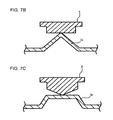
- FIG. 7B is a schematic sectional view of a combination of the protruding section of the inner panel and a rivet.
- FIG. 7C is a schematic sectional view of a combination of the protruding section of the inner panel and a rivet.
- FIG. 7D is a schematic sectional view of a combination of the protruding section of the inner panel and a rivet.
- FIG. 8B is a schematic sectional view showing the rivet mounting method in terms of the order of steps.
- FIG. 9A is a schematic sectional view showing a different rivet mounting method in terms of the order of steps.
- FIG. 9B is a schematic sectional view showing the different rivet mounting method in terms of the order of steps.
- FIG. 9C is a schematic sectional view showing the different rivet mounting method in terms of the order of steps.
- FIGS. 1A and 1B are schematic views of a deformation process of a different materials panel structure 101 caused by thermal expansion and contraction when bake-coating panels.
- FIG. 1A is a schematic view of the entire different materials panel structure 101
- FIG. 1B is an enlarged sectional view of a hemmed section 104 thereof.
- an outer panel 102 is formed from an aluminum alloy plate
- an inner panel 103 is formed from a steel plate.
- the linear expansion coefficient of the outer panel 102 is greater than the linear expansion coefficient of the inner panel 103 .
- the inner panel 103 is disposed at a lower-surface side of the outer panel 102 .
- the outer panel 102 contracts. This phenomenon corresponds to a change in the linear length of the outer panel 102 . This causes the outer panel 102 of the different materials panel structure 101 shown in FIG. 1A to warp upward. When such a warping occurs in the outer panel 102 , the entire different materials panel structure 101 or corners of the different materials panel structure 101 are deformed. Therefore, it is difficult to form an automobile panel having high form accuracy.
- FIG. 2A is a schematic view of a structure when the different materials panel structure using a rivet 106 is subjected to spot welding.
- a portion to which the rivet is joined is provided with a heat insulation section, which includes an adhesive layer or an adhesive layer and a gap, between the inner panel and the outer panel in order to prevent the welding heat from being transferred to the outer panel.
- FIG. 3 is a bottom view of an engine hood, which is an exemplary different materials panel structure 1 .
- FIG. 4 is a sectional view of a hemmed section 4 of the different materials panel structure 1 according to the embodiment. As shown in FIG. 3 , in the different materials panel structure 1 according to the embodiment, the hemmed section 4 is formed by bending peripheral edge portions of an outer panel 2 , and sandwiching end portions of an inner panel 3 by the bent portions. In addition to being applicable to the hood (bonnet) shown in FIG. 3 , the different materials panel structure 1 according to the embodiment is applicable to various other types of members for an automobile body, such as a trunk and a door panel. Naturally, the solid shape, the planar shape, and a hem processing range differ according to the application of these panels.
- the outer panel 2 is a flat-plate-like member that is curved in a three-dimensional arc shape in its entirety towards an outer side of a vehicle body.
- the outer panel 2 is formed by forming, for example, an aluminum plate or an aluminum alloy plate into a predetermined shape by using various forming methods, such as press forming.
- the aluminum alloy used in the outer panel 2 may be selected as appropriate in accordance with required characteristics of a vehicle body structure that is used, such as strength, formability, and corrosion resistance.
- As the aluminum alloy for the outer panel 2 for example, aluminum alloys, such as 3000 series, 5000 series, 6000 series, and 7000 series aluminum alloys, in conformity with JIS and AA Standard may be used.
- Si/Mg silicon-magnesium ratio
- the outer panel 2 is formed, such 6000 series aluminum alloy plates ensure formability by reduced strength (yield strength).
- the 6000 series aluminum alloy plates have a characteristic (bake hardening characteristic or BH characteristic) in which the strength (yield strength) is increased, when the 6000 series aluminum alloy plates undergo age-hardening due to an artificial aging treatment for a short time of 10 to 50 minutes at a low temperature of 150 to 180° C. in a subsequent baking operation.
- the aforementioned aluminum alloy material is, for example, subjected to solution treatment and hardening (temper designation T 4 ) and subsequent aging treatment (temper symbol T 6 , etc.), and overaging treatment (temper symbol T 7 ), so that a press forming material of the outer panel 2 is formed.
- the thickness (plate thickness) of the aluminum alloy plate for the outer panel 2 is generally selected from thicknesses in the range of 0.5 to 3 mm as appropriate.
- the aluminum alloy plate is too thin, the required strength and rigidity as an automobile member may not be ensured.
- the aluminum alloy plate is too thick, the weight of the automobile body cannot be reduced, as a result of which hem processing becomes difficult to perform.
- the inner panel 3 is a member that has the shape of a hat in cross section (that is, its cross-sectional shape is a cross-sectional HAT shape).
- the inner panel 3 is formed by forming, for example, an iron plate or an iron alloy plate, such as a steel plate, into a predetermined shape by using various forming methods, such as press forming.
- the inner panel 3 includes a hollow protruding section 3 a on at least a portion of the inner panel 3 to which a rivet 6 is joined.
- the melting point of the inner panel 3 is higher than the melting point of the outer panel 2 .
- FIGS. 5A to 5G are each a schematic perspective view of an exemplary shape of the protruding section 3 a of the inner panel 3 .
- the external shape of the protruding section 3 a of the inner panel 3 is not particularly limited to certain external shapes as long as it is a hollow protruding section.
- the protruding section 3 a may have various shapes, such as a conical shape shown in FIG. 5A , a circular truncated conical shape shown in FIG. 5B , a frustum shape shown in FIG. 5C , a rectangular column shape shown in FIG. 5D , a dome shape shown in FIG. 5E , and a bead shape shown in FIG. 5F .
- the height of the protruding section 3 a is also not particularly limited to certain heights, and may be selected as appropriate according to an application member. However, the height is desirably in the range of 0.1 to 2.0 mm, and more desirably in the range of 0.3 to 1.5 mm.
- a heat insulation section 8 that includes an adhesive layer or an adhesive layer and a gap is formed between the protruding section 3 a and the outer panel 2 , and heat of a melted portion 7 that is produced during welding and joining operations can be prevented from being transferred to the outer panel 2 .
- the thickness (plate thickness) of the steel plate is selected from thicknesses in the range of 0.3 to 3 mm as appropriate.
- the steel plate is too thin, the required strength and rigidity as an automobile member may not be ensured.
- the steel plate is too thick, it becomes difficult to reduce the weight of the automobile body.
- the hemmed section 4 is formed by hem bending (bending) the peripheral edge portions of the outer panel 2 .
- the hemmed section 4 joins the outer panel 2 to the inner panel 3 via an adhesive layer 9 .
- the adhesive layer 9 is described later.
- FIGS. 6A to 6D are each a sectional view of an exemplary rivet structure.
- FIGS. 7A to 7D are each a schematic sectional view of a combination of the protruding section 3 a of the inner panel and the rivet 6 .
- FIGS. 8A and 8B are schematic sectional views showing a rivet- 6 mounting method in terms of the order of steps
- FIGS. 9A, 9B, and 9C are schematic sectional views showing a different rivet- 6 mounting method in terms of the order of steps.
- the rivet 6 includes a head section 6 a and a shaft section 6 b .
- the shape of the rivet 6 is not particularly limited to certain shapes, so that the rivet 6 may have a shape whose end has a conical shape as shown in FIGS. 6A and 6D , or whose end is flat as shown in FIGS. 6B and 6C .
- the shape and size of the head section 6 a and the shaft section 6 b may be selected as appropriate according to use and method.
- the combination of the rivet 6 and the protruding section 3 a of the inner panel 3 is also not particularly limited to certain combinations.
- the protruding section 3 a has a conical shape or a pyramidal shape
- the protruding section 3 a has a circular truncated conical shape or a frustum shape
- the rivet 6 whose end has a conical shape may be brought into contact with and welded to the protruding section 3 a as shown in FIG. 7C
- the rivet 6 may be welded with an end of the rivet 6 being pushed into the protruding section 3 a as shown in FIG. 7D .
- the rivet 6 that is used is one that is made of the same type of metallic material as the inner panel 3 . Therefore, a fragile intermetallic compound is not formed at a joint, so that the joining strength can be kept high. When the joining strength between the rivet 6 and the inner panel 3 is low, hem displacement can no longer be sufficiently prevented.
- the inner panel 3 is made of a steel material
- by also forming the rivet 6 out of a steel material, such as soft steel it is possible to perform spot welding by using an existing steel material spot welding line.
- a portion of the rivet 6 that contacts the outer panel 2 be provided with a film made of a material having a resistivity that is higher than that of the material of the inner panel 3 , such as a steel material.
- the high-resistance film that is provided on the rivet 6 include a film made of a metal having a relatively high resistivity, such as zinc, lead, or aluminum; a film made of a synthetic resin, such as a polyester resin or a silicone resin, a film made of an oxide of iron (mill scale), and an electroless Ni—P plated film.
- the high-resistance film that is provided on the rivet 6 may be an insulating film that is formed by using a commercially available surface treatment agent, such as DISGO (registered trademark), GEOMET (registered trademark), or LAFRE (registered trademark).
- the head section 6 a and/or the shaft section 6 b of the rivet 6 be caulked to the outer panel 2 .
- the rivet 6 is no longer removed during transport until a welding step. Therefore, after the welding, it is possible to maintain the minimum joining strength with respect to the outer panel 2 even if the adhesive layer 9 deteriorates with time.
- the caulking may be performed by driving the rivet 6 into the outer panel 2 and causing the member to be fastened (the outer panel 2 ) to undergo plastic flow to the head section 6 a .
- the caulking may be performed by, with a preparation hole formed in the member to be fastened (the outer panel 2 ) in advance, causing the member to be fastened (the outer panel 2 ) to undergo plastic flow and to be caulked to the head section 6 a of the rivet 6 .
- the preparation hole is formed by punching out a portion 2 a of the outer panel 2 with punching jigs 11 a and 11 b .
- the rivet 6 including the shaft section 6 b having a diameter that is smaller than that of the preparation hole is inserted into the preparation hole, and upsetting is performed on the rivet 6 in an axial direction to thicken the shaft section 6 b , so that the rivet 6 can be caulked to the outer panel 2 .
- the different materials panel structure 1 includes the adhesive layer 9 between the outer panel 2 and the inner panel 3 .
- the peripheral edge portions of the outer panel 2 are folded back, the peripheral edge portions of the outer panel 2 sandwich the peripheral edge portions of flanges of the inner panel 3 via the adhesive layer 9 , so that they are integrated with each other. Therefore, the hemmed section 4 having a layered structure in which the peripheral edge portions of the outer panel 2 and the peripheral edge portions of the flanges of the inner panel 3 are combined with each other via the adhesive layer 9 is formed, so that they are integrated with each other as the different materials panel structure 1 .
- thermosetting resin adhesive can prevent electrolytic corrosion that occurs when different materials, that is, aluminum and iron, directly contact each other, and can increase the joining strength between the different materials (different materials panel structure). Therefore, it is desirable that the adhesive be applied around (so as to surround) the entire peripheral edge portions of the outer panel 2 .
- thermoplastic resin adhesive that forms the adhesive layer 9 only needs to be an adhesive that hardens when baking and hardening the automobile body panels, and that can exhibit the required adhesive strength as the different materials panel structure.
- thermoplastic resin adhesive that forms the adhesive layer 9 include an epoxy resin adhesive, a polyester resin adhesive, and a phenol resin adhesive.
- an end of the shaft section 6 b of the rivet 6 and the inner panel 3 are welded to each other by resistance spot welding. Even if the adhesive layer 9 exists between the inner panel 3 and the outer panel 2 , the resistance spot welding can be performed while removing the adhesive layer 9 at a joint by pressing the electrodes. Therefore, the resistance spot welding is suitable from the viewpoint of joining strength.
- the plate used be a block member or a panel that is made of a material having high thermal conductivity, such as a steel plate, or having a flow path that allows a coolant to flow therethrough.
- the protruding section 3 a is formed at a joint of the inner panel 3 . Therefore, the heat insulation section 8 that includes the adhesive layer or the adhesive layer and the gap is formed at a back surface of the protruding section 3 a so as to be disposed between the protruding section 3 a and the outer panel 2 . Further, since the protruding section 3 a is hollow, the heat insulation section 8 that includes the adhesive layer or the adhesive layer and the gap is thickly formed. This blocks or considerably reduces heat transfer to the outer panel 2 . As a result, the softening of the outer panel 2 is reduced, so that bulging of the outer panel 2 that occurs when an end of the rivet is pushed can be suppressed.
- the hollow protruding section 3 a is formed at a portion of the inner panel 3 to which the rivet 6 is joined, and the heat insulation section 8 that includes the adhesive layer or the adhesive layer and the gap is formed between the inner panel 3 and the outer panel 2 . Therefore, welding heat is no longer directly transferred to the outer panel 2 . As a result, a softened portion is less likely to be formed on the outer panel 2 , so that a bulging portion is not formed in the outer panel 2 . Accordingly, it is possible to manufacture an automobile panel having excellent appearance without, for example, making small adjustments.
- the rivet and the outer panel were sandwiched by a pair of electrodes.
- the pressing force being from 5 kN to 300 kN
- the current value being from 1 kA to 10 kA
- the energizing time being from 10 milliseconds to 40 milliseconds
- spot welding was performed.
- a heat insulation section of approximately 0.5 mm was formed between the inner panel and the outer panel according to Example 1.
- Comparative Example 1 a structure, in which an inner panel without a protruding section was sandwiched in a hemmed section of an outer panel via a layer of adhesive, and a rivet, which was the same as that in Example 1, was driven into the outer panel, was prepared.
- Comparative Example 2 a structure, in which an inner panel was joined to an outer panel by using only an adhesive without driving a rivet into the outer panel was prepared.
- An outer surface of the outer panel after the welding was measured by using a 3D shape measuring instrument (WYCO NT9300, manufactured by VECCO).
- Example 1 and Comparative Example 2 in which welding was not performed a bulging portion was not formed in the outer panel, and that the unevenness of a surface of the outer panel at a joint was 15 ⁇ m or less and the smoothness of the surface of the outer panel was good.
- Example 2 Although there were no hem displacements in the hemmed joints in Example 1 and Comparative Example 1, the hemmed joints were displaced by approximately 10 mm in Comparative Example 2.
- Tensile test pieces were formed by cutting the hemmed joints after the welding in Example 1 and Comparative Example 1 to a width of 30 mm. Then, an end portion of the hemmed section of each outer panel and its corresponding inner panel were chucked, and was pulled in a perpendicular direction (an axial direction) with respect to the shaft of its corresponding rivet to confirm breakage states of the joints.
- Example 1 and Comparative Example 1 were both 3 kN.
- the breakage position was not at a welded metallic portion. Breakage of a base material (plug failure) occurred at a side of the GA steel material. Therefore, it was confirmed that good joint strength was obtained.
Landscapes
- Engineering & Computer Science (AREA)
- Mechanical Engineering (AREA)
- General Engineering & Computer Science (AREA)
- Chemical & Material Sciences (AREA)
- Combustion & Propulsion (AREA)
- Transportation (AREA)
- Architecture (AREA)
- Structural Engineering (AREA)
- Connection Of Plates (AREA)
- Body Structure For Vehicles (AREA)
- Superstructure Of Vehicle (AREA)
- Standing Axle, Rod, Or Tube Structures Coupled By Welding, Adhesion, Or Deposition (AREA)
- Resistance Welding (AREA)
Applications Claiming Priority (5)
| Application Number | Priority Date | Filing Date | Title |
|---|---|---|---|
| JP2014022827 | 2014-02-07 | ||
| JP2014-022827 | 2014-02-07 | ||
| JP2014236158A JP5908052B2 (ja) | 2014-02-07 | 2014-11-21 | 異材パネル構造体 |
| JP2014-236158 | 2014-11-21 | ||
| PCT/JP2015/051199 WO2015118931A1 (ja) | 2014-02-07 | 2015-01-19 | 異材パネル構造体 |
Publications (2)
| Publication Number | Publication Date |
|---|---|
| US20160339966A1 US20160339966A1 (en) | 2016-11-24 |
| US9751571B2 true US9751571B2 (en) | 2017-09-05 |
Family
ID=53777738
Family Applications (1)
| Application Number | Title | Priority Date | Filing Date |
|---|---|---|---|
| US15/112,004 Expired - Fee Related US9751571B2 (en) | 2014-02-07 | 2015-01-19 | Different materials panel structure |
Country Status (6)
| Country | Link |
|---|---|
| US (1) | US9751571B2 (de) |
| EP (1) | EP3103706A4 (de) |
| JP (1) | JP5908052B2 (de) |
| KR (1) | KR101800569B1 (de) |
| CN (1) | CN105722748B (de) |
| WO (1) | WO2015118931A1 (de) |
Cited By (5)
| Publication number | Priority date | Publication date | Assignee | Title |
|---|---|---|---|---|
| US20190203754A1 (en) * | 2017-12-28 | 2019-07-04 | Honda Motor Co., Ltd. | Device and method of applying a sealant around a structural adhesive to prevent corrosion |
| US20200368802A1 (en) * | 2019-05-20 | 2020-11-26 | Kabushiki Kaisha Kobe Seiko Sho (Kobe Steel, Ltd.) | Method for manufacturing vehicular side door, door component, and side door |
| US20210115954A1 (en) * | 2018-05-17 | 2021-04-22 | Atlas Copco Ias Uk Limited | Method for joining two workpieces |
| US11027496B2 (en) | 2018-02-01 | 2021-06-08 | Dr. Ing. H.C. F. Porsche Aktiengesellschaft | Adhesive bonding and sealing of seams and joints |
| US11549535B2 (en) | 2017-04-19 | 2023-01-10 | Nhk Spring Co., Ltd. | Joined body, automobile seat frame, and joining method |
Families Citing this family (32)
| Publication number | Priority date | Publication date | Assignee | Title |
|---|---|---|---|---|
| DE102014018994A1 (de) * | 2014-12-18 | 2016-06-23 | GM Global Technology Operations LLC (n. d. Gesetzen des Staates Delaware) | Fahrzeugkarosserie mit geklebtem Fahrzeugdach sowie Verfahren zur Herstellung eines Kraftfahrzeuges |
| JP6109271B2 (ja) * | 2015-02-06 | 2017-04-05 | 株式会社神戸製鋼所 | 接合構造体、及び接合構造体の製造方法 |
| JP2016190627A (ja) * | 2015-03-31 | 2016-11-10 | 三菱重工業株式会社 | 構造体製造装置、構造体製造方法、および構造体 |
| JP6411993B2 (ja) * | 2015-12-25 | 2018-10-24 | 株式会社神戸製鋼所 | 異材接合構造体 |
| JP6574724B2 (ja) * | 2016-03-08 | 2019-09-11 | 株式会社神戸製鋼所 | 異材パネル構造体 |
| CN105818866B (zh) * | 2016-03-28 | 2019-04-05 | 福建省汽车工业集团云度新能源汽车股份有限公司 | 一种汽车引擎盖及加工方法 |
| US20200298340A1 (en) * | 2016-03-30 | 2020-09-24 | Panasonic Intellectual Property Management Co., Ltd. | Joint structure |
| CN106218729B (zh) * | 2016-07-29 | 2018-04-17 | 奇瑞汽车股份有限公司 | 一种汽车前舱盖总成 |
| CN109641312B (zh) * | 2016-08-27 | 2021-12-28 | 有限会社新城控股 | 结合装置 |
| WO2018142994A1 (ja) * | 2017-01-31 | 2018-08-09 | パナソニックIpマネジメント株式会社 | 接合構造 |
| US10611125B2 (en) * | 2017-02-06 | 2020-04-07 | GM Global Technology Operations LLC | Method for joining dissimilar metals and articles comprising the same |
| WO2018193839A1 (ja) * | 2017-04-19 | 2018-10-25 | 日本発條株式会社 | 接合体、自動車用シートフレームおよび接合方法 |
| JP6819517B2 (ja) * | 2017-09-05 | 2021-01-27 | トヨタ自動車株式会社 | 車体構造 |
| KR102398894B1 (ko) | 2017-12-08 | 2022-05-18 | 현대자동차주식회사 | 하이브리드 도어의 헤밍 구조 및 하이브리드 도어의 헤밍 방법 |
| KR20190070414A (ko) | 2017-12-13 | 2019-06-21 | 현대자동차주식회사 | 하이브리드 도어의 헤밍 구조 |
| KR102398893B1 (ko) * | 2017-12-13 | 2022-05-18 | 현대자동차주식회사 | 하이브리드 도어의 헤밍 구조 |
| DE102018107563B4 (de) * | 2018-03-29 | 2022-03-03 | Infineon Technologies Austria Ag | Halbleitervorrichtung mit kupferstruktur und verfahren zur herstellung einer halbleitervorrichung |
| CN109396627A (zh) * | 2018-09-26 | 2019-03-01 | 首钢集团有限公司 | 异种材料连接装置及连接方法 |
| CN111098938B (zh) * | 2018-10-26 | 2023-08-15 | 蔚来(安徽)控股有限公司 | 用于车身结构的部件及其制造方法 |
| KR102142786B1 (ko) * | 2018-11-30 | 2020-08-07 | 주식회사 포스코 | 헤밍 방법 및 이를 이용하여 가공된 패널 조립체 |
| JP7421135B2 (ja) * | 2019-03-27 | 2024-01-24 | 日本製鉄株式会社 | 継手構造、自動車部品及び継手構造の製造方法 |
| US11286005B2 (en) * | 2019-09-03 | 2022-03-29 | Honda Motor Co., Ltd. | Hood frame reinforcement for deflection mitigation |
| DE102019007558A1 (de) * | 2019-10-30 | 2021-05-06 | Man Truck & Bus Se | Baukastensystem und Verbindungseinrichtung für Kraftfahrzeug-Luftleitelemente |
| DE102020119196A1 (de) * | 2020-07-21 | 2022-01-27 | Bayerische Motoren Werke Aktiengesellschaft | Außenhautbauteil für ein Kraftfahrzeug und Verfahren zur Herstellung eines Außenhautbauteils |
| JP7405717B2 (ja) * | 2020-08-28 | 2023-12-26 | 株式会社神戸製鋼所 | 異材接合方法、及び接合体 |
| KR20220101372A (ko) * | 2021-01-11 | 2022-07-19 | 현대자동차주식회사 | 열팽창율이 다른 이종 재질로 이루어지는 차량용 패널어셈블리 |
| US11465227B2 (en) * | 2021-02-12 | 2022-10-11 | GM Global Technology Operations LLC | System and method for manufacturing high-strength bonded metal sheets for a battery cell |
| EP4350158A4 (de) * | 2021-05-26 | 2024-10-16 | Nippon Steel Corporation | Fahrzeugplattenstruktur |
| CN113623298A (zh) * | 2021-08-11 | 2021-11-09 | 上汽通用汽车有限公司 | 一种金属板与复合材料板的连接结构及连接工艺 |
| KR20230091625A (ko) | 2021-12-16 | 2023-06-23 | 주식회사 포스코 | 적층복합패널의 점용접방법 |
| US20230416576A1 (en) * | 2022-06-23 | 2023-12-28 | Rivian Ip Holdings, Llc | Adhesive additive for electrical conductivity and methods for manufacturing the same |
| KR102845491B1 (ko) * | 2022-11-03 | 2025-08-13 | 주식회사 새한산업 | 차체 후드 제조방법 |
Citations (11)
| Publication number | Priority date | Publication date | Assignee | Title |
|---|---|---|---|---|
| JPS5680380A (en) | 1979-12-04 | 1981-07-01 | Mazda Motor Corp | Fixing inner and outer plate of lid or the like for motorcar |
| JPS61202621A (ja) | 1985-03-05 | 1986-09-08 | 三菱農機株式会社 | コンバインにおける穀稈揚送供給装置 |
| US4738560A (en) * | 1984-10-12 | 1988-04-19 | Bayerische Motoren Werke Ag | Welding seam for the connection of two thin sheet metal members |
| JPH07214338A (ja) | 1994-01-28 | 1995-08-15 | Nippon Steel Corp | 鉄系金属材料とアルミニウム系金属材料との接合方法 |
| US6528176B1 (en) * | 1999-06-09 | 2003-03-04 | Sanyo Machine Works, Ltd. | Structure of hemmed together metal plate materials |
| US6806436B2 (en) * | 2000-12-06 | 2004-10-19 | Toyota Shatai Kabushiki Kaisha | Series spot welding method, device for carrying out the method, and electrodes employed in the method or the device |
| WO2007063646A1 (ja) | 2005-11-29 | 2007-06-07 | Kabushiki Kaisha Kobe Seiko Sho | 異材接合体 |
| JP2007283313A (ja) | 2006-04-12 | 2007-11-01 | Kobe Steel Ltd | 異材接合体 |
| CN101590598A (zh) | 2008-05-28 | 2009-12-02 | 株式会社神户制钢所 | 钢材和轻合金材的异种材料的接合方法 |
| JP2014000580A (ja) | 2012-06-18 | 2014-01-09 | Kobe Steel Ltd | 異材接合体、異材接合体用構造体、及び、異材接合体用リベット |
| US9180548B2 (en) * | 2008-06-06 | 2015-11-10 | GM Global Technology Operations LLC | Method for one-sided, one step joining of a metal sheet stack |
Family Cites Families (5)
| Publication number | Priority date | Publication date | Assignee | Title |
|---|---|---|---|---|
| JPS61202821A (ja) * | 1985-03-06 | 1986-09-08 | Mazda Motor Corp | 積層合板を備えた板材の接合方法 |
| ITTO980547A1 (it) * | 1998-06-25 | 1999-12-25 | Pierino Garnero | Procedimento per l'esecuzione di punti di saldatura elettrica a resi- stenza fra una prima lamiera costituita da un materiale non saldabile |
| JP2007185690A (ja) * | 2006-01-13 | 2007-07-26 | Honda Motor Co Ltd | 車体部材のヘミング接合方法およびヘミング接合構造 |
| JP5704798B2 (ja) * | 2009-03-11 | 2015-04-22 | 株式会社神戸製鋼所 | 異材接合方法 |
| JP5952596B2 (ja) | 2012-03-08 | 2016-07-13 | 株式会社神戸製鋼所 | 異材パネル構造体およびその製造方法 |
-
2014
- 2014-11-21 JP JP2014236158A patent/JP5908052B2/ja not_active Expired - Fee Related
-
2015
- 2015-01-19 US US15/112,004 patent/US9751571B2/en not_active Expired - Fee Related
- 2015-01-19 WO PCT/JP2015/051199 patent/WO2015118931A1/ja not_active Ceased
- 2015-01-19 EP EP15746942.0A patent/EP3103706A4/de not_active Withdrawn
- 2015-01-19 CN CN201580002593.8A patent/CN105722748B/zh not_active Expired - Fee Related
- 2015-01-19 KR KR1020167021393A patent/KR101800569B1/ko not_active Expired - Fee Related
Patent Citations (12)
| Publication number | Priority date | Publication date | Assignee | Title |
|---|---|---|---|---|
| JPS5680380A (en) | 1979-12-04 | 1981-07-01 | Mazda Motor Corp | Fixing inner and outer plate of lid or the like for motorcar |
| US4427869A (en) | 1979-12-04 | 1984-01-24 | Toyo Kogyo Co., Ltd. | Method for manufacturing panel assemblies for automobiles |
| US4738560A (en) * | 1984-10-12 | 1988-04-19 | Bayerische Motoren Werke Ag | Welding seam for the connection of two thin sheet metal members |
| JPS61202621A (ja) | 1985-03-05 | 1986-09-08 | 三菱農機株式会社 | コンバインにおける穀稈揚送供給装置 |
| JPH07214338A (ja) | 1994-01-28 | 1995-08-15 | Nippon Steel Corp | 鉄系金属材料とアルミニウム系金属材料との接合方法 |
| US6528176B1 (en) * | 1999-06-09 | 2003-03-04 | Sanyo Machine Works, Ltd. | Structure of hemmed together metal plate materials |
| US6806436B2 (en) * | 2000-12-06 | 2004-10-19 | Toyota Shatai Kabushiki Kaisha | Series spot welding method, device for carrying out the method, and electrodes employed in the method or the device |
| WO2007063646A1 (ja) | 2005-11-29 | 2007-06-07 | Kabushiki Kaisha Kobe Seiko Sho | 異材接合体 |
| JP2007283313A (ja) | 2006-04-12 | 2007-11-01 | Kobe Steel Ltd | 異材接合体 |
| CN101590598A (zh) | 2008-05-28 | 2009-12-02 | 株式会社神户制钢所 | 钢材和轻合金材的异种材料的接合方法 |
| US9180548B2 (en) * | 2008-06-06 | 2015-11-10 | GM Global Technology Operations LLC | Method for one-sided, one step joining of a metal sheet stack |
| JP2014000580A (ja) | 2012-06-18 | 2014-01-09 | Kobe Steel Ltd | 異材接合体、異材接合体用構造体、及び、異材接合体用リベット |
Non-Patent Citations (1)
| Title |
|---|
| International Search Report and Written Opinion issued Apr. 21, 2015 in PCT/JP2015/051199 filed Jan. 19, 2015. |
Cited By (7)
| Publication number | Priority date | Publication date | Assignee | Title |
|---|---|---|---|---|
| US11549535B2 (en) | 2017-04-19 | 2023-01-10 | Nhk Spring Co., Ltd. | Joined body, automobile seat frame, and joining method |
| US20190203754A1 (en) * | 2017-12-28 | 2019-07-04 | Honda Motor Co., Ltd. | Device and method of applying a sealant around a structural adhesive to prevent corrosion |
| US11060543B2 (en) * | 2017-12-28 | 2021-07-13 | Honda Motor Co., Ltd. | Device and method of applying a sealant around a structural adhesive to prevent corrosion |
| US11027496B2 (en) | 2018-02-01 | 2021-06-08 | Dr. Ing. H.C. F. Porsche Aktiengesellschaft | Adhesive bonding and sealing of seams and joints |
| US20210115954A1 (en) * | 2018-05-17 | 2021-04-22 | Atlas Copco Ias Uk Limited | Method for joining two workpieces |
| US11873857B2 (en) * | 2018-05-17 | 2024-01-16 | Atlas Copco Ias Uk Limited | Method for joining two workpieces |
| US20200368802A1 (en) * | 2019-05-20 | 2020-11-26 | Kabushiki Kaisha Kobe Seiko Sho (Kobe Steel, Ltd.) | Method for manufacturing vehicular side door, door component, and side door |
Also Published As
| Publication number | Publication date |
|---|---|
| JP5908052B2 (ja) | 2016-04-26 |
| EP3103706A1 (de) | 2016-12-14 |
| KR101800569B1 (ko) | 2017-11-22 |
| EP3103706A4 (de) | 2017-09-20 |
| US20160339966A1 (en) | 2016-11-24 |
| CN105722748A (zh) | 2016-06-29 |
| CN105722748B (zh) | 2018-08-03 |
| JP2015164840A (ja) | 2015-09-17 |
| WO2015118931A1 (ja) | 2015-08-13 |
| KR20160105889A (ko) | 2016-09-07 |
Similar Documents
| Publication | Publication Date | Title |
|---|---|---|
| US9751571B2 (en) | Different materials panel structure | |
| JP5704798B2 (ja) | 異材接合方法 | |
| JP6278154B2 (ja) | 抵抗スポット溶接方法および溶接部材の製造方法 | |
| JP6148136B2 (ja) | 異材接合体の製造方法 | |
| US20080026247A1 (en) | Method and apparatus for bonding dissimilar materials made from metals | |
| KR102001797B1 (ko) | 이재 패널 구조체 | |
| US20180222150A1 (en) | Method for joining dissimilar metals and articles comprising the same | |
| JP2015062911A (ja) | 異材接合体の製造方法 | |
| JP2008284570A (ja) | 異種金属の接合方法及び接合装置 | |
| JP2016161078A (ja) | 異材接合用リベット及び異材接合方法 | |
| JPWO2017033455A1 (ja) | 抵抗スポット溶接方法および溶接部材の製造方法 | |
| JP2010065916A (ja) | 熱交換器及びその製造方法 | |
| JP7255652B2 (ja) | ウェルドボンド継手の製造方法 | |
| JP2007144473A (ja) | 異材接合体 | |
| JP7364902B2 (ja) | リベット接合継手構造の製造方法、リベット接合継手構造および自動車部品 | |
| JP6094440B2 (ja) | 異種金属材料の抵抗溶接方法及び車両用部品 | |
| JP7485242B1 (ja) | 溶接部材およびその製造方法 | |
| WO2018088367A1 (ja) | 接合構造体及びその製造方法 | |
| JP6424264B2 (ja) | 接合体、自動車用シートフレームおよび接合方法 | |
| JP2008036704A (ja) | アルミ製品と鋼材製品との接合用継ぎ手及びそれを用いた接合方法 | |
| KR102241138B1 (ko) | 이종소재 패치워크 및 이의 제조방법 | |
| JP2007283313A (ja) | 異材接合体 | |
| JP6591952B2 (ja) | 接合構造体及びその製造方法 | |
| KR102871621B1 (ko) | 용접 이음매, 용접 부재 및 그 제조 방법, 그리고 저항 스폿 용접 방법 | |
| JP2025070084A (ja) | 金属接合体の製造方法 |
Legal Events
| Date | Code | Title | Description |
|---|---|---|---|
| AS | Assignment |
Owner name: KABUSHIKI KAISHA KOBE SEIKO SHO (KOBE STEEL, LTD.) Free format text: ASSIGNMENT OF ASSIGNORS INTEREST;ASSIGNORS:IWASE, TETSU;IMAMURA, YOSHIHAYA;REEL/FRAME:039167/0529 Effective date: 20150601 |
|
| STCF | Information on status: patent grant |
Free format text: PATENTED CASE |
|
| MAFP | Maintenance fee payment |
Free format text: PAYMENT OF MAINTENANCE FEE, 4TH YEAR, LARGE ENTITY (ORIGINAL EVENT CODE: M1551); ENTITY STATUS OF PATENT OWNER: LARGE ENTITY Year of fee payment: 4 |
|
| FEPP | Fee payment procedure |
Free format text: MAINTENANCE FEE REMINDER MAILED (ORIGINAL EVENT CODE: REM.); ENTITY STATUS OF PATENT OWNER: LARGE ENTITY |
|
| LAPS | Lapse for failure to pay maintenance fees |
Free format text: PATENT EXPIRED FOR FAILURE TO PAY MAINTENANCE FEES (ORIGINAL EVENT CODE: EXP.); ENTITY STATUS OF PATENT OWNER: LARGE ENTITY |
|
| STCH | Information on status: patent discontinuation |
Free format text: PATENT EXPIRED DUE TO NONPAYMENT OF MAINTENANCE FEES UNDER 37 CFR 1.362 |
|
| FP | Lapsed due to failure to pay maintenance fee |
Effective date: 20250905 |