US9599316B2 - Light source device using monochromatic light to excite stationary phosphor layers - Google Patents
Light source device using monochromatic light to excite stationary phosphor layers Download PDFInfo
- Publication number
- US9599316B2 US9599316B2 US14/414,029 US201314414029A US9599316B2 US 9599316 B2 US9599316 B2 US 9599316B2 US 201314414029 A US201314414029 A US 201314414029A US 9599316 B2 US9599316 B2 US 9599316B2
- Authority
- US
- United States
- Prior art keywords
- light
- wavelength
- light source
- monochromatic
- phosphor layer
- Prior art date
- Legal status (The legal status is an assumption and is not a legal conclusion. Google has not performed a legal analysis and makes no representation as to the accuracy of the status listed.)
- Active, expires
Links
Images


Classifications
-
- F—MECHANICAL ENGINEERING; LIGHTING; HEATING; WEAPONS; BLASTING
- F21—LIGHTING
- F21V—FUNCTIONAL FEATURES OR DETAILS OF LIGHTING DEVICES OR SYSTEMS THEREOF; STRUCTURAL COMBINATIONS OF LIGHTING DEVICES WITH OTHER ARTICLES, NOT OTHERWISE PROVIDED FOR
- F21V13/00—Producing particular characteristics or distribution of the light emitted by means of a combination of elements specified in two or more of main groups F21V1/00 - F21V11/00
- F21V13/02—Combinations of only two kinds of elements
- F21V13/08—Combinations of only two kinds of elements the elements being filters or photoluminescent elements and reflectors
-
- F—MECHANICAL ENGINEERING; LIGHTING; HEATING; WEAPONS; BLASTING
- F21—LIGHTING
- F21V—FUNCTIONAL FEATURES OR DETAILS OF LIGHTING DEVICES OR SYSTEMS THEREOF; STRUCTURAL COMBINATIONS OF LIGHTING DEVICES WITH OTHER ARTICLES, NOT OTHERWISE PROVIDED FOR
- F21V13/00—Producing particular characteristics or distribution of the light emitted by means of a combination of elements specified in two or more of main groups F21V1/00 - F21V11/00
- F21V13/12—Combinations of only three kinds of elements
- F21V13/14—Combinations of only three kinds of elements the elements being filters or photoluminescent elements, reflectors and refractors
-
- F—MECHANICAL ENGINEERING; LIGHTING; HEATING; WEAPONS; BLASTING
- F21—LIGHTING
- F21V—FUNCTIONAL FEATURES OR DETAILS OF LIGHTING DEVICES OR SYSTEMS THEREOF; STRUCTURAL COMBINATIONS OF LIGHTING DEVICES WITH OTHER ARTICLES, NOT OTHERWISE PROVIDED FOR
- F21V9/00—Elements for modifying spectral properties, polarisation or intensity of the light emitted, e.g. filters
- F21V9/08—Elements for modifying spectral properties, polarisation or intensity of the light emitted, e.g. filters for producing coloured light, e.g. monochromatic; for reducing intensity of light
-
- F—MECHANICAL ENGINEERING; LIGHTING; HEATING; WEAPONS; BLASTING
- F21—LIGHTING
- F21V—FUNCTIONAL FEATURES OR DETAILS OF LIGHTING DEVICES OR SYSTEMS THEREOF; STRUCTURAL COMBINATIONS OF LIGHTING DEVICES WITH OTHER ARTICLES, NOT OTHERWISE PROVIDED FOR
- F21V9/00—Elements for modifying spectral properties, polarisation or intensity of the light emitted, e.g. filters
- F21V9/14—Elements for modifying spectral properties, polarisation or intensity of the light emitted, e.g. filters for producing polarised light
-
- G—PHYSICS
- G02—OPTICS
- G02B—OPTICAL ELEMENTS, SYSTEMS OR APPARATUS
- G02B27/00—Optical systems or apparatus not provided for by any of the groups G02B1/00 - G02B26/00, G02B30/00
- G02B27/10—Beam splitting or combining systems
- G02B27/1006—Beam splitting or combining systems for splitting or combining different wavelengths
- G02B27/102—Beam splitting or combining systems for splitting or combining different wavelengths for generating a colour image from monochromatic image signal sources
-
- G—PHYSICS
- G03—PHOTOGRAPHY; CINEMATOGRAPHY; ANALOGOUS TECHNIQUES USING WAVES OTHER THAN OPTICAL WAVES; ELECTROGRAPHY; HOLOGRAPHY
- G03B—APPARATUS OR ARRANGEMENTS FOR TAKING PHOTOGRAPHS OR FOR PROJECTING OR VIEWING THEM; APPARATUS OR ARRANGEMENTS EMPLOYING ANALOGOUS TECHNIQUES USING WAVES OTHER THAN OPTICAL WAVES; ACCESSORIES THEREFOR
- G03B21/00—Projectors or projection-type viewers; Accessories therefor
- G03B21/14—Details
- G03B21/20—Lamp housings
- G03B21/2006—Lamp housings characterised by the light source
- G03B21/2013—Plural light sources
-
- G—PHYSICS
- G03—PHOTOGRAPHY; CINEMATOGRAPHY; ANALOGOUS TECHNIQUES USING WAVES OTHER THAN OPTICAL WAVES; ELECTROGRAPHY; HOLOGRAPHY
- G03B—APPARATUS OR ARRANGEMENTS FOR TAKING PHOTOGRAPHS OR FOR PROJECTING OR VIEWING THEM; APPARATUS OR ARRANGEMENTS EMPLOYING ANALOGOUS TECHNIQUES USING WAVES OTHER THAN OPTICAL WAVES; ACCESSORIES THEREFOR
- G03B21/00—Projectors or projection-type viewers; Accessories therefor
- G03B21/14—Details
- G03B21/20—Lamp housings
- G03B21/2006—Lamp housings characterised by the light source
- G03B21/2033—LED or laser light sources
- G03B21/204—LED or laser light sources using secondary light emission, e.g. luminescence or fluorescence
-
- G—PHYSICS
- G03—PHOTOGRAPHY; CINEMATOGRAPHY; ANALOGOUS TECHNIQUES USING WAVES OTHER THAN OPTICAL WAVES; ELECTROGRAPHY; HOLOGRAPHY
- G03B—APPARATUS OR ARRANGEMENTS FOR TAKING PHOTOGRAPHS OR FOR PROJECTING OR VIEWING THEM; APPARATUS OR ARRANGEMENTS EMPLOYING ANALOGOUS TECHNIQUES USING WAVES OTHER THAN OPTICAL WAVES; ACCESSORIES THEREFOR
- G03B21/00—Projectors or projection-type viewers; Accessories therefor
- G03B21/14—Details
- G03B21/20—Lamp housings
- G03B21/2073—Polarisers in the lamp house
-
- G—PHYSICS
- G03—PHOTOGRAPHY; CINEMATOGRAPHY; ANALOGOUS TECHNIQUES USING WAVES OTHER THAN OPTICAL WAVES; ELECTROGRAPHY; HOLOGRAPHY
- G03B—APPARATUS OR ARRANGEMENTS FOR TAKING PHOTOGRAPHS OR FOR PROJECTING OR VIEWING THEM; APPARATUS OR ARRANGEMENTS EMPLOYING ANALOGOUS TECHNIQUES USING WAVES OTHER THAN OPTICAL WAVES; ACCESSORIES THEREFOR
- G03B21/00—Projectors or projection-type viewers; Accessories therefor
- G03B21/14—Details
- G03B21/20—Lamp housings
- G03B21/208—Homogenising, shaping of the illumination light
-
- G—PHYSICS
- G03—PHOTOGRAPHY; CINEMATOGRAPHY; ANALOGOUS TECHNIQUES USING WAVES OTHER THAN OPTICAL WAVES; ELECTROGRAPHY; HOLOGRAPHY
- G03B—APPARATUS OR ARRANGEMENTS FOR TAKING PHOTOGRAPHS OR FOR PROJECTING OR VIEWING THEM; APPARATUS OR ARRANGEMENTS EMPLOYING ANALOGOUS TECHNIQUES USING WAVES OTHER THAN OPTICAL WAVES; ACCESSORIES THEREFOR
- G03B33/00—Colour photography, other than mere exposure or projection of a colour film
- G03B33/10—Simultaneous recording or projection
- G03B33/12—Simultaneous recording or projection using beam-splitting or beam-combining systems, e.g. dichroic mirrors
-
- H—ELECTRICITY
- H04—ELECTRIC COMMUNICATION TECHNIQUE
- H04N—PICTORIAL COMMUNICATION, e.g. TELEVISION
- H04N9/00—Details of colour television systems
- H04N9/12—Picture reproducers
- H04N9/31—Projection devices for colour picture display, e.g. using electronic spatial light modulators [ESLM]
- H04N9/3102—Projection devices for colour picture display, e.g. using electronic spatial light modulators [ESLM] using two-dimensional electronic spatial light modulators
- H04N9/3111—Projection devices for colour picture display, e.g. using electronic spatial light modulators [ESLM] using two-dimensional electronic spatial light modulators for displaying the colours sequentially, e.g. by using sequentially activated light sources
-
- H—ELECTRICITY
- H04—ELECTRIC COMMUNICATION TECHNIQUE
- H04N—PICTORIAL COMMUNICATION, e.g. TELEVISION
- H04N9/00—Details of colour television systems
- H04N9/12—Picture reproducers
- H04N9/31—Projection devices for colour picture display, e.g. using electronic spatial light modulators [ESLM]
- H04N9/3141—Constructional details thereof
- H04N9/315—Modulator illumination systems
- H04N9/3158—Modulator illumination systems for controlling the spectrum
-
- H—ELECTRICITY
- H04—ELECTRIC COMMUNICATION TECHNIQUE
- H04N—PICTORIAL COMMUNICATION, e.g. TELEVISION
- H04N9/00—Details of colour television systems
- H04N9/12—Picture reproducers
- H04N9/31—Projection devices for colour picture display, e.g. using electronic spatial light modulators [ESLM]
- H04N9/3141—Constructional details thereof
- H04N9/315—Modulator illumination systems
- H04N9/3164—Modulator illumination systems using multiple light sources
Definitions
- the present invention relates to a light source device, more particularly to a light source device used in a projection display device.
- LED light emitting diode
- laser light sources including a plurality of laser emitting elements
- Patent reference 1 discloses a light source device in which excitation light excites a phosphor, and the excited phosphor outputs light (output light) in a certain wavelength band when it returns to its ground state.
- the excitation light radiated from the excitation light source irradiates a phosphor wheel.
- the phosphor wheel has a segment area with a phosphor layer that emits light in a red wavelength band, a segment area with a phosphor layer that emits light in a green wavelength band, and a segment area with a phosphor layer that emits light in a blue wavelength band.
- LEDs or laser emitting elements are used as the excitation light source.
- a wheel motor spins the phosphor wheel so that the excitation light excites the phosphor of the color in each segment area in turn.
- Patent reference 1 proposes a light source device that outputs output light of each color (light in the wavelength band of each color) in turn.
- phosphors of three colors are disposed in segment areas that are placed in a separated arrangement in the circumferential direction of the phosphor wheel. That is, the output light of each color is output at a different time, which constrains the controlled emission of the output light of each color (the light in the wavelength band of each color). Since the period during which output light of each color (light in the wavelength band of each color) is emitted is restricted, that is, control of the amount of emitted light of each color must take place within a restricted emission period. Control of the amount of emitted light of each color in correspondence to the input image is consequently restricted.
- An object of the present invention is therefore to provide a light source device that uses a plurality of types of light emitted from a plurality of phosphor layers, mitigates the restrictions on the emission periods, and improves the controllability of the amount of emitted light of each color.
- a light source device has a first monochromatic light source group for outputting first polarized light with a fixed polarization direction, a second monochromatic light source group for outputting second polarized light with a fixed polarization direction, a polarization selection and wavelength selection element, a first phosphor layer for emitting light in a first wavelength band when excited, and a second phosphor layer for emitting light in a second wavelength band when excited.
- the polarization selection and wavelength selection element directs the first polarized light onto the first phosphor layer by transmitting the first polarized light and directs the second polarized light onto the second phosphor layer by reflecting the second polarized light, and reflects the light in the first wavelength band emitted from the first phosphor layer and transmits the light in the second wavelength band emitted from the second phosphor layer.
- a plurality of types of light emitted from a plurality of phosphor layers are used, the restrictions on the emission periods can be mitigated, and the controllability of the amount of emitted light of each color can be improved.
- FIG. 1 is a diagram schematically illustrating a configuration of a light source device and a projection display device according to a first embodiment of the invention.
- FIG. 2 is a frontal view schematically illustrating the first monochromatic light source group and the second monochromatic light source group in FIG. 1 .
- FIGS. 3( a ) and 3( b ) are a side view and a frontal view schematically illustrating the shape of the polarization selection and wavelength selection element in FIG. 1 .
- FIG. 4 is a diagram illustrating polarization separation characteristics and wavelength separation characteristics of the polarization selection and wavelength selection element in FIG. 1 .
- FIG. 5 is a perspective view schematically illustrating a light intensity uniformization element in FIG. 1 .
- FIG. 6 is a diagram illustrating polarization separation characteristics and wavelength separation characteristics of another polarization selection and wavelength selection element that can be used in the first embodiment.
- FIG. 7 is a diagram schematically illustrating a configuration of a light source device and a projection display device according to a second embodiment of the invention.
- FIG. 8 is a diagram illustrating polarization separation characteristics of a polarization selection element in FIG. 7 .
- FIG. 9 is a diagram schematically illustrating a configuration of a light source device and a projection display device according to a third embodiment of the invention.
- FIGS. 10( a ) and 10( b ) are schematic frontal views illustrating a lens array in FIG. 9 .
- FIG. 11 is a diagram schematically illustrating a configuration of a light source device and a projection display device according to a fourth embodiment of the invention.
- FIG. 12 is a diagram that explains a reference standard of an axis of polarization (polarization direction).
- FIGS. 13( a ) and 13( b ) are diagrams illustrating wavelength separation characteristics of two wavelength selection elements shown in FIG. 11 .
- FIG. 14 is a diagram illustrating wavelength separation characteristic when the two wavelength separation elements shown in FIG. 11 are implemented with a single wavelength selection element.
- FIG. 15 is a diagram showing an exemplary relative light intensity curve (relative light intensity at each wavelength) of light emitted by excitation of a phosphor layer for color green and a phosphor layer for color red.
- FIG. 16 is a diagram schematically illustrating a variation of the configuration of the light source device and the projection display device according to the fourth embodiment of the invention.
- FIG. 17 is a diagram schematically illustrating a variation of the configuration of the light source device and the projection display device according to the fourth embodiment of the invention.
- FIG. 18 is a diagram illustrating polarization separation characteristics of a color separation element.
- FIG. 19 is a diagram schematically illustrating a configuration of a light source device and a projection display device according to a fifth embodiment of the invention.
- FIG. 20 is a diagram illustrating wavelength selection characteristic of a color separation element.
- FIG. 21 is a diagram illustrating wavelength selection characteristic of a color separation element.
- FIG. 22 is a diagram illustrating wavelength selection characteristic of a color separation element.
- Patent reference 2 proposes a light source device that outputs light in a green wavelength band and light in a blue wavelength band in turn by means of a matrix arrangement of a plurality of blue laser light sources and a rotating phosphor wheel, and outputs red light from an independent red LED (see, for example, paragraphs 0072-0088 and FIGS. 1, 8, and 9 in patent reference 2).
- this light source device uses an LED having a large emitting surface and a large scattering angle as a red light source, however, there is a problem of low light utilization efficiency.
- FIG. 1 is a diagram schematically illustrating a configuration of a projection display device 1 including a light source device 4 according to a first embodiment of the invention.
- FIG. 1 shows an orthogonal XYZ coordinate system.
- the X-axis direction is the vertical direction in FIG. 1 .
- the down-to-up direction in FIG. 1 is the positive X-axis direction; the up-to-down direction is the negative X-axis direction.
- a lens group 13 , a light reflecting element 12 , first collimating lenses 11 a , second collimating lenses 11 b , first monochromatic light sources 10 a , and second monochromatic light sources 10 b are disposed on the positive X-axis side of a polarization selection and wavelength selection element 14 .
- the Y-axis direction is the direction perpendicular to the drawing sheet on which FIG. 1 is depicted.
- the positive Y-axis direction is the direction from the reverse side (back side) to the front side of the drawing sheet; the negative Y-axis direction is the direction from the front side to the reverse side (back side) of the drawing sheet.
- the Z-axis direction is the horizontal direction in FIG. 1 .
- a color separation element 19 is disposed on the positive Z-axis side of the polarization selection and wavelength selection element 14 .
- a ‘color separation element’ is a ‘wavelength selection element’.
- the projection display device 1 includes the light source device 4 , the light intensity uniformization element 72 , the image display element or a light valve 74 , and the projection optics 75 as shown in FIG. 1 .
- the projection display device 1 may also include the focusing lens 71 , the relay lens group 73 , and the screen 76 . Light flux output from the light source device 4 is focused onto an incidence surface 72 a of the light intensity uniformization element 72 by the focusing lens 71 .
- FIG. 1 shows an example in which the light valve 74 is a transmissive image display element (e.g., a transmissive liquid crystal display element or the like).
- the image display element is a transmissive liquid crystal display element, polarizing plates must be placed on an incidence side and an exit side of the liquid crystal display element, but they are omitted here for convenience.
- the light valve 74 may be a reflective image display element (e.g., a reflective liquid crystal display element, a digital micromirror device (DMD), or the like).
- the projection display device 1 may have a rear projection type of configuration in which the screen 76 is transmissive and the displayed image is observed through the screen (from a position on the positive Z-axis side of the screen 76 ).
- the projection display device 1 may have a front projection type of configuration in which the displayed image is observed from the front of the screen (from a position on the negative Z-axis side of the screen 76 ).
- the shapes and arrangement of the focusing lens 71 , the light intensity uniformization element 72 , the relay lens group 73 , the light valve 74 , the projection optics 75 , and the screen 76 are not limited to the illustrated example; many variations are possible.
- the term ‘light valve’ denotes an image display element.
- the ‘image display element’ is an element for converting light into image light.
- image light denotes light carrying image information (i.e., light that has been spatially modulated according to image information). An example using a light valve will be described below.
- the light source device 4 in the first embodiment includes a first monochromatic light source group 1000 a , a second monochromatic light source group 1000 b , a polarization selection and wavelength selection element (also referred to as a ‘polarization selection-wavelength selection element’) 14 , a first phosphor layer 16 a , and a second phosphor layer 16 b .
- the light source device 4 in the first embodiment may further include a first collimating lens group 1100 a , a second collimating lens group 1100 b , a light reflecting element 12 , a lens group 13 , a first focusing lens group 15 a , and a second focusing lens group 15 b .
- the light source device 4 in the first embodiment may include third monochromatic light sources 17 a , 17 b , third collimating lenses 18 a , 18 b , and a color separation element 19 , as shown in FIG. 1 .
- FIG. 2 is a frontal view schematically illustrating the first monochromatic light source group 1000 a and the second monochromatic light source group 1000 b in FIG. 1 .
- the first monochromatic light sources 10 a and the second monochromatic light sources 10 b in FIG. 2 alternate in two orthogonal directions. The ‘two orthogonal directions’ are the vertical direction and the horizontal direction in FIG. 2 .
- the first monochromatic light source group 1000 a includes a plurality of first monochromatic light sources 10 a .
- the first monochromatic light sources 10 a output first polarized light having a fixed polarization direction.
- the first collimating lens group 1100 a includes a plurality of first collimating lenses 11 a .
- the first monochromatic light sources 10 a and the first collimating lenses 11 a are in one to one correspondence.
- the light output from the first monochromatic light sources 10 a is collimated by the first collimating lenses 11 a .
- Other arrangements of the plurality of first monochromatic light sources 10 a may be used.
- the term ‘polarized light’ denotes light having a fixed polarization direction; ‘light having a fixed polarization direction’ is, for example, linearly polarized light whose plane of polarization is limited to a single plane.
- Linearly polarized light whose plane of polarization is limited to a single plane will be referred to here as polarized light for convenience, but output of elliptically polarized light as well as linearly polarized light is also contemplated.
- Elliptically polarized light can produce the same effects as linearly polarized light.
- the second monochromatic light source group 1000 b includes a plurality of second monochromatic light sources 10 b .
- the second monochromatic light sources 10 b output second polarized light having a fixed polarization direction.
- the polarization direction of the second polarized light differs by 90 degrees from the polarization direction of the first polarized light.
- the second collimating lens group 1100 b includes a plurality of second collimating lenses 11 b .
- the second monochromatic light sources 10 b and the second collimating lenses 11 b are in one to one correspondence. Light output from the second monochromatic light sources 10 b is collimated by the second collimating lenses 11 b .
- Other arrangements of the plurality of second monochromatic light sources 10 b may also be used.
- Each of the plurality of first monochromatic light sources 10 a is, for example, a blue laser light emitting element (blue laser diode).
- Each of the plurality of second monochromatic light sources 10 b is, for example, a blue laser light emitting element (blue laser diode).
- the first embodiment describes a case in which the wavelength band of the light output from the first monochromatic light sources 10 a and the wavelength band of the light emitted from the second monochromatic light source 10 b are the same.
- the wavelength band of the light output from the first monochromatic light sources 10 a may differ, however, from the wavelength band of the light output from the second monochromatic light sources 10 b.
- the light (e.g., blue laser light) emitted from the first monochromatic light sources 10 a is the first polarized light having a fixed polarization direction.
- the light (e.g., blue laser light) emitted from the second monochromatic light source 10 b is the second polarized light having a fixed polarization direction.
- the polarization direction of the first polarized light differs by 90 degrees from the polarization direction of the second polarized light.
- the first polarized light incident on the polarization selection and wavelength selection element 14 is p-polarized light and the second polarized light is s-polarized light.
- the first collimating lens group 1100 a includes the plurality of first collimating lenses 11 a .
- the first monochromatic light sources 10 a and the first collimating lenses 11 a are in one to one correspondence.
- the light output from the first monochromatic light sources 10 a is collimated by the first collimating lenses 11 a.
- the second collimating lens group 1100 b includes the plurality of second collimating lenses 11 b .
- the second monochromatic light sources 10 b and the second collimating lenses 11 b are in one to one correspondence.
- the light output from the second monochromatic light sources 10 b is collimated by the second collimating lenses 11 b.
- the first collimating lens group 1100 a and the second collimating lens group 1100 b may each be a single unitary lens array. If the first collimating lens group 1100 a and the second collimating lens group 1100 b are each a single unitary lens array, it is possible to mitigate the reduction in light utilization efficiency caused by installation variations of the first collimating lenses 11 a and the second collimating lenses 11 b .
- installation variations denotes variations in the positions of parts determined by their machining tolerances or assembly tolerances.
- ‘Installation variations’ are caused by lens eccentricity etc.
- ‘Eccentricity’ means that an optical axis of a lens or an optical element deviates from an intended optical axis.
- Eccentricity includes eccentricity (decentering) arising from an offset of an optical axis of a lens or an optical element in a plane perpendicular to an ideal optical axis, and eccentricity (tilt) arising when an optical axis of a lens or an optical element is inclined from or rotated with respect to an ideal optical axis.
- eccentricity decentering
- tilt eccentricity
- installation variations of the first collimating lenses 11 a and the second collimating lenses 11 b can be suppressed by mold precision and forming precision.
- the light reflecting element 12 bends the light path of the first polarized light that has been output from the first monochromatic light sources 10 a and has passed through the first collimating lenses 11 a by 90 degrees.
- the light reflecting element 12 also bends the light path of the second polarized light that has been output from the second monochromatic light sources 10 b and has passed through the second collimating lenses 11 b by 90 degrees.
- the light reflecting surface of the light reflecting element 12 is preferably formed with, for example, a silver coating that can efficiently reflect blue light.
- the size of the light source device 4 can thereby be reduced by shortening its length in the X-axis direction.
- the lens group 13 has functions such as, for example, collimating and reducing the diameter of the light flux from the light reflecting element 12 .
- the lens group 13 includes, for example, a first lens and a second lens.
- the configuration of the lens group 13 is not limited to the example shown in FIG. 1 .
- the lens group 13 may consist of a single lens.
- the lens group 13 may also consist of three or more lenses.
- the light source device 4 may be configured without the lens group 13 .
- the following embodiments show optical elements for reducing the diameter of the light flux as the lens group.
- the first focusing lens group 15 a focuses the first polarized light in combination with the lens group 13 , for example.
- the first focusing lens group 15 a includes a first focusing lens 15 a 1 and a second focusing lens 15 a 2 .
- the configuration of the first focusing lens group 15 a is not limited to the example shown in FIG. 1 .
- the first focusing lens group 15 a may consist of a single lens.
- the first focusing lens group 15 a may also consist of three or more lenses. Allowing for a single or multiple-lens configuration, the first focusing lens group 15 a may be denoted as a first focusing element 15 a.
- the second focusing lens group 15 b focuses the second polarized light in combination with the lens group 13 .
- the second focusing lens group 15 b includes a first focusing lens 15 b 1 and a second focusing lens 15 b 2 .
- the configuration of the second focusing lens group 15 b is not limited to the example shown in FIG. 1 .
- the second focusing lens group 15 b may consist of a single lens.
- the second focusing lens group 15 b may also consist of three or more lenses. Allowing for a single or multiple-lens configuration, the second focusing lens group 15 b may be denoted as a second focusing element 15 b.
- the first phosphor layer 16 a receives the first polarized light as excitation light.
- the first phosphor layer 16 a is excited by the first polarized light and thereby emits light in a first wavelength band.
- the light in the first wavelength band is, for example, light in a red wavelength band.
- the second phosphor layer 16 b receives the second polarized light as excitation light.
- the second phosphor layer 16 b is excited by the second polarized light and thereby emits light in a second wavelength band.
- the light in the second wavelength band is, for example, light in a green wavelength band.
- FIGS. 3( a ) and 3( b ) are a side view and a frontal view schematically illustrating the shape of the polarization selection and wavelength selection element 14 in FIG. 1 .
- FIG. 3( a ) is the side view.
- FIG. 3( b ) is the frontal view.
- the polarization selection and wavelength selection element 14 has a polarization selection function and a wavelength selection function.
- the ‘polarization selection function’ is a function that reflects or transmits light according to the direction of polarization of the light.
- the ‘wavelength selection function’ is a function that reflects or transmits light according to the wavelength of the light.
- the polarization selection and wavelength selection element 14 has property of transmitting p-polarized light and reflecting s-polarized light (a polarization selection function) and property of separating colors formed in a multilayer dielectric film (a wavelength selection function).
- the polarization selection and wavelength selection element 14 transmits the first polarized light by means of its polarization selection function.
- the first focusing lens group 15 a collects the first polarized light and directs the collected light onto the first phosphor layer 16 a .
- the polarization selection and wavelength selection element 14 reflects the second polarized light by means of its polarization selection function.
- the second focusing lens group 15 b collects the second polarized light and directs the collected light onto the second phosphor layer 16 b.
- the polarization selection and wavelength selection element 14 uses its wavelength selection function to reflect the light in the first wavelength band emitted from the first phosphor layer 16 a .
- the polarization selection and wavelength selection element 14 uses its wavelength selection function to transmit the light in the second wavelength band emitted from the second phosphor layer 16 b.
- FIG. 4 is a schematic diagram illustrating optical transmission characteristics of the polarization selection and wavelength selection element 14 with respect to wavelength.
- the horizontal axis represents wavelength [nm] of light and the vertical axis represents optical transmittance [%].
- a curve 200 p represents the optical transmission characteristic for p-polarized light incident on the polarization selection and wavelength selection element 14 .
- the curve 200 p is shown by a dot-dash line.
- a curve 200 s represents the optical transmission characteristic for s-polarized light incident on the polarization selection and wavelength selection element 14 .
- the curve 200 s is shown by a dotted line.
- the polarization selection and wavelength selection element 14 has different optical transmission characteristics for p-polarized light and s-polarized light.
- the curve 200 p in FIG. 4 shows the optical transmittance increasing from a wavelength of 430 nm (more precisely speaking, near 430 nm), and becoming 100% at a wavelength of 445 nm (more precisely speaking, near 445 nm).
- the curve 200 p also shows the optical transmittance decreasing from a wavelength of 595 nm (more precisely speaking, near 595 nm) and becoming 0% at a wavelength of 610 nm (more precisely speaking, near 610 nm).
- the curve 200 s shows the optical transmittance increasing from a wavelength of 445 nm (more precisely speaking, near 445 nm), and becoming 100% at a wavelength of 460 nm (more precisely speaking, near 460 nm).
- the curve 200 s also shows the optical transmittance decreasing from a wavelength of 575 nm (more precisely speaking, near 575 nm) and becoming 0% at a wavelength of 590 nm (more precisely speaking, near 590 nm).
- the expression ‘more precisely speaking’ indicates that variations in characteristics that occur when actual parts are manufactured are taken into consideration. The same applies to the following description.
- the polarization selection and wavelength selection element 14 can be used as a polarization selection element for light in the wavelength bands W1 and W2 indicated by the double-headed arrows in FIG. 4 .
- the polarization selection and wavelength selection element 14 can also be used as a wavelength selection element (a color band filter) for light of wavelengths other than the wavelength bands W1 and W2 indicated by the double-headed arrows in FIG. 4 .
- a wavelength selection element a color band filter
- the wavelength band W1 is a band from 440 nm to 450 nm (more precisely speaking, a band from approximately 440 nm to approximately 450 nm).
- the wavelength band W2 is a band from 585 nm to 600 nm (more precisely speaking, a band from approximately 585 nm to approximately 600 nm).
- the wavelength band W2 on the longer wavelength side is generally wider than the wavelength band W1 on the shorter wavelength side here.
- the optical transmittance of p-polarized light is 90% or more and the optical reflectance of s-polarized light is 90% or more. Characteristics at wavelengths less than 440 nm do not matter.
- the optical transmittance of p-polarized light may be 30% and the optical reflectance of s-polarized light may be 60%.
- the wavelength band for which the polarization selection function is used is used.
- the optical transmittance and optical reflectance characteristics for polarized light in the range from 440 nm to 450 nm are important.
- this embodiment uses the wavelength selection function but does not use the polarization selection function, so the wavelength band W2 is less important, as long as polarized light of red wavelengths is reflected. If the wavelength band W2 extends from 585 nm to 600 nm, that is, the reflectance of light of wavelengths longer than 600 nm is preferably high regardless of the polarization direction.
- the blue laser light used for excitation is indicated by a curve 200 in FIG. 4 . Since the curve 200 indicates laser light, it has a relatively narrow wavelength band.
- the wavelength band of the blue laser light used for excitation is, for example, the band from 444 nm to 446 nm.
- FIG. 4 illustrates the characteristics of the polarization selection and wavelength selection element 14 when the first phosphor layer 16 a outputs light in the red wavelength band and the second phosphor layer 16 b outputs light in the green wavelength band.
- the center wavelength of the first polarized light from the first monochromatic light sources 10 a is 445 [nm] and the center wavelength of the second polarized light from the second monochromatic light sources 10 b is also 445 [nm].
- the curve 200 s of the polarization selection and wavelength selection element 14 it suffices for the curve 200 s of the polarization selection and wavelength selection element 14 to be reflective below 470 nm and the curve 200 p to be reflective below 460 nm. That is, 90% or more of the p-polarized light should be transmitted and 90% or more of the s-polarized light should be reflected in the wavelength band from 460 nm to 470 nm.
- the light transmitted through the polarization selection and wavelength selection element 14 is focused onto the first phosphor layer 16 a by the first focusing lens group 15 a .
- the light reflected by the polarization selection and wavelength selection element 14 is focused onto the second phosphor layer 16 b by the second focusing lens group 15 b .
- the first focusing lens group 15 a and the second focusing lens group 15 b are preferably of different design here.
- the lenses 15 a 1 and 15 b 1 are spherical lenses and the lenses 15 a 2 and 15 b 2 are aspherical lenses, for example, thicknesses, curvatures, and positions of the lenses 15 a 1 and 15 b 1 nearest the phosphor layers 16 a and 16 b , respectively, are designed corresponding to the color of light excited from the phosphor layers 16 a and 16 b .
- the lens 15 a 1 is the lens nearest the first phosphor layer 16 a .
- the lens 15 b 1 is the lens nearest the second phosphor layer 16 b .
- the lens 15 a 2 is the lens second nearest the first phosphor layer 16 a .
- the lens 15 b 2 is the lens second nearest the second phosphor layer 16 b .
- the second nearest lenses 15 a 2 and 15 b 2 are aspherical lenses, so from the viewpoint of cost, it is preferable that they be shared. In this case, for the second nearest lenses 15 a 2 and 15 b 2 it is preferable to select a low-dispersion glass material.
- the term ‘low-dispersion’ means that the Abbe number is large.
- the term ‘low-dispersion’ also means that the wavelength dependency of the refractive index is small.
- the first phosphor layer 16 a is excited by the excitation light to emit light in the red wavelength band.
- the second phosphor layer 16 b is excited by the excitation light to emit light in the green wavelength band.
- the case of excitation by blue laser light is described here. That is, the excitation light is blue laser light.
- the third monochromatic light sources 17 a and 17 b are, for example, blue laser light sources.
- the third collimating lenses 18 a and 18 b output light that are output from the third monochromatic light sources 17 a and 17 b , respectively, as collimated light fluxes.
- the color separation element 19 is formed as, for example, a multilayer dielectric film.
- the color separation element 19 has the property of transmitting the colors red and green and reflecting the color blue.
- the light from the third monochromatic light sources 17 a , 17 b is reflected by the color separation element 19 .
- the light from the third monochromatic light sources 17 a , 17 b is then focused by the focusing lens 71 onto the light intensity uniformization element 72 .
- the light incident from the polarization selection and wavelength selection element 14 onto the color separation element 19 is transmitted through the color separation element 19 .
- the light incident from the polarization selection and wavelength selection element 14 onto the color separation element 19 is then focused by the focusing lens 71 onto the light intensity uniformization element 72 .
- FIG. 5 is a perspective view of the light intensity uniformization element 72 .
- the light intensity uniformization element 72 uniformizes the light intensity of light entering from the incidence surface 72 a , in the cross section of the light flux. ‘In the cross section of the light flux’ means in a plane orthogonal to the optical axis C1 of the light intensity uniformization element 72 . To ‘uniformize the light intensity’ is to reduce illuminance irregularities.
- the light intensity uniformization element 72 outputs a light flux with a uniformized light intensity from its exit surface 72 b . That is, the light intensity uniformization element 72 has the function of uniformizing the light intensity of the incident light flux within a plane orthogonal to the optical axis C1 and outputting the resultant light flux.
- the light intensity uniformization element 72 is generally made from glass, plastic, or some other transparent material.
- One possible light intensity uniformization element 72 is a polygonal columnar rod configured to have totally reflecting inside walls. That is, it is a columnar member whose plane cross section orthogonal to the optical axis C1 is a polygon.
- Another possible light intensity uniformization element 72 is a pipe (tubular member) with a polygonal cross sectional shape built with light reflecting surfaces on the inside.
- the light intensity uniformization element 72 reflects incident light multiple times by using the total reflection effect at the interface between the transparent material and air, and then outputs the light from the exit surface 72 b .
- the light intensity uniformization element 72 When the light intensity uniformization element 72 is a pipe with a polygonal cross section, the light intensity uniformization element 72 reflects incident light multiple times by using the reflective effect of inwardly facing surface mirrors, and then outputs the light from the exit surface 72 b .
- the light intensity uniformization element 72 can internally reflect light multiple times if it has an appropriate length in the direction of propagation of the light flux. The light that has been internally reflected multiple times floods the exit surface 72 b of the light intensity uniformization element 72 . This provides a uniform light intensity distribution on the exit surface 72 b of the light intensity uniformization element 72 .
- the relay lens group 73 in FIG. 1 has a three-lens configuration, but this is not a limitation.
- the relay lens group 73 may be configured with four lenses and may use aspherical lenses. Besides lenses, the relay lens group 73 may be configured to use flat mirrors and curved mirrors to guide the light flux to the light valve 74 .
- the light valve 74 is, for example, a liquid crystal light valve or a DMD.
- a projection display device using a liquid crystal light valve uses a first lens array and a second lens array with a plurality of lens cells arranged in a matrix to uniformize the light intensity and provides a polarization conversion element in the stage following the second lens array to align the polarization direction, thereby increasing the light utilization efficiency.
- a projection display device 1 as shown in FIG.
- the first embodiment shows a single DMD but three DMDs may be used. In that case, the first embodiment makes it possible to keep red light, green light, and blue light turned on at all times, suppressing the reduction in brightness due to the effect of time division driving of the DMD.
- the light source device 4 and the projection display device 1 use the polarization selection and wavelength selection element 14 to separate the laser light from the blue laser light emitting elements that form the light source for excitation. If the blue laser light emitting elements are turned on constantly, it becomes possible to output red light and green light constantly. If the blue laser light emitting elements with different polarizations are turned on selectively, quantities of light of each color can be output according to the input image. Consequently, the effect of improved light utilization efficiency can be obtained from the light source device 4 and the projection display device 1 .
- the focusing lens groups for the first phosphor layer 16 a and the second phosphor layer 16 b can be independent, so they can be designed for the colors red and green.
- the light source device 4 and the projection display device 1 can therefore produce the effect of enhanced efficiency in concentrating light onto the light intensity uniformization element 72 .
- FIG. 6 is a schematic diagram showing another example of the optical transmission characteristics of the polarization selection and wavelength selection element 14 with respect to wavelength.
- the horizontal axis represents wavelength [nm] of light and the vertical axis represents optical transmittance [%].
- a curve 201 p represents the optical transmission characteristic for p-polarized light incident on the polarization selection and wavelength selection element 14 .
- a curve 201 s represents the optical transmittance characteristic for s-polarized light incident on the polarization selection and wavelength selection element 14 .
- the polarization selection and wavelength selection element 14 has different optical transmission characteristics for p-polarized light and s-polarized light.
- the curve 201 s in FIG. 6 shows the optical transmittance decreasing from a wavelength of 430 nm (more precisely speaking, near 430 nm), and becoming 0% at a wavelength of 445 nm (more precisely speaking, near 445 nm).
- the curve 201 s also shows the optical transmittance increasing from a wavelength of 595 nm (more precisely speaking, near 595 nm) and becoming 100% at a wavelength of 610 nm (more precisely speaking, near 610 nm).
- the curve 201 p shows the optical transmittance decreasing from a wavelength of 445 nm (more precisely speaking, near 445 nm), and becoming 0% at a wavelength of 460 nm (more precisely speaking, near 460 nm).
- the curve 201 p also shows the optical transmittance increasing from a wavelength of 575 nm (more precisely speaking, near 575 nm) and becoming 100% at a wavelength of 590 nm (more precisely speaking, near 590 nm).
- This difference in optical transmission characteristics causes light in wavelength bands W3 and W4 indicated by double-headed arrows in FIG. 6 to be transmitted through the polarization selection and wavelength selection element 14 if the light is p-polarized light and reflected by the polarization selection and wavelength selection element 14 if the light is s-polarized light. That is, the polarization selection and wavelength selection element 14 can be used as a polarization selection element for light in the wavelength bands W3 and W4 indicated by the double-headed arrows in FIG. 6 .
- the polarization selection and wavelength selection element 14 can also be used as a wavelength selection element (a color band filter) for light of wavelengths other than the wavelength bands W3 and W4 indicated by the double-headed arrows in FIG. 6 .
- the wavelength band W3 is a band from 440 nm to 450 nm (more precisely speaking, a band from approximately 440 nm to approximately 450 nm); the wavelength band W4 is a band from 585 nm to 600 nm (more precisely speaking, a band from approximately 585 nm to approximately 600 nm).
- the wavelength band W4 on the longer wavelength side is generally wider than the wavelength W3 on the shorter wavelength side here.
- the optical transmittance of p-polarized light is 90% or more and the reflectance of s-polarized light is 90% or more. Characteristics at wavelengths less than 440 nm do not matter.
- the optical transmittance of p-polarized light may be 60% and the reflectance of s-polarized light may be 30%. What matters here is the optical transmittance and reflectance characteristics for polarized light in the range from 440 nm to 450 nm, in which the polarization selection function is used.
- the wavelength band W4 is less important, as long as polarized light of a red wavelength is transmitted. If the wavelength band W4 extends from 585 nm to 600 nm, the transmittance of light of wavelengths longer than 600 nm is preferably high regardless of the polarization direction.
- the blue laser light used for excitation is indicated by a curve 200 in FIG. 6 . Since the curve 200 indicates laser light, it has a relatively small wavelength band. In FIG. 6 , the wavelength band of the blue laser light used for excitation is, for example, from 444 nm to 446 nm.
- FIG. 6 illustrates the characteristics of the polarization selection and wavelength selection element 14 when the first phosphor layer 16 a outputs light in the green wavelength band and the second phosphor layer 16 b outputs light in the red wavelength band.
- the center wavelength of the first polarized light from the first monochromatic light sources 10 a is 445 [nm] and the center wavelength of the second polarized light from the second monochromatic light sources 10 b is also 445 [nm].
- the curve 201 p of the polarization selection and wavelength selection element 14 it suffices for the curve 201 p of the polarization selection and wavelength selection element 14 to be transmissive below 470 nm and the curve 201 s to be transmissive below 460 nm. That is, 90% or more of the p-polarized light should be transmitted and 90% or more of the s-polarized light should be reflected in the wavelength band from 460 nm to 470 nm.
- the first embodiment shows a case in which the first phosphor layer 16 a and the second phosphor layer 16 b are coated onto flat plates.
- the first phosphor layer 16 a and the second phosphor layer 16 b may, however, be coated onto rotary plates turned by a driving force of a motor or the like.
- the first phosphor layer 16 a is coated onto a first rotary plate and the second phosphor layer 16 b is coated onto a second rotary plate.
- a heat sink or some other type of cooling structure is generally provided on the rear surface of each of the first phosphor layer 16 a and the second phosphor layer 16 b .
- the cooling structure may be omitted. This is because when a rotary plate is used, the position of light irradiation is constantly changing, which mitigates an increase in the temperature of the phosphor.
- the third monochromatic light sources 17 a and 17 b are blue laser emitting elements, but they may be blue LEDs. In this case, however, since an LED has a wide light divergence angle, it is necessary for the third collimating lens 18 a and the third collimating lens 18 b to be aspherical lenses or for the number of lenses to be increased. Alternatively, they must be aspherical lenses as used for the first focusing lens groups 15 a and 15 b , in order to collimate the light flux.
- the light source device 4 includes the first monochromatic light source group 1000 a , the second monochromatic light source group 1000 b , the polarization selection and wavelength selection element 14 , the first phosphor layer 16 a , and the second phosphor layer 16 b .
- the first monochromatic light source group 1000 a outputs the first polarized light having a fixed polarization direction.
- the second monochromatic light source group 1000 b outputs the second polarized light having a fixed polarization direction.
- the first phosphor layer 16 a When excited, the first phosphor layer 16 a outputs light in the first wavelength band.
- the second phosphor layer 16 b outputs light in the second wavelength band.
- the polarization selection and wavelength selection element 14 transmits the first polarized light to direct the first polarized light onto the first phosphor layer 16 a and reflects the second polarized light to direct the second polarized light onto the second phosphor layer 16 b .
- the polarization selection and wavelength selection element 14 reflects the light in the first wavelength band emitted from the first phosphor layer 16 a and transmits the light in the second wavelength band emitted from the second phosphor layer 16 b.
- the second polarized light has a polarization direction differing by 90 degrees from the polarization direction of the first polarized light.
- the light source device 4 includes the first focusing lens element 15 a disposed on the light path of the first polarized light between the polarization selection and wavelength selection element 14 and the first phosphor layer 16 a , and the second focusing lens element 15 b disposed on the light path of the second polarized light between the polarization selection and wavelength selection element 14 and the second phosphor layer 16 b .
- the focusing lens groups 15 a and 15 b may be described as the focusing elements 15 a and 15 b.
- the light source device 4 has a third monochromatic light source group 1700 and the color separation element 19 .
- the third monochromatic light source group 1700 outputs light in a third wavelength band.
- the color separation element 19 brings the light path of light in the third wavelength band into coincidence with the common light path shared by the light path of the light in the first wavelength band that has been reflected by the polarization selection and wavelength selection element 14 and the light path of the light in the second wavelength band that has been transmitted through the polarization selection and wavelength selection element 14 .
- the first polarized light is p-polarized light at the time of incidence on the polarization selection and wavelength selection element 14 ; the second polarized light is s-polarized light at the time of incidence on the polarization selection and wavelength selection element 14 .
- the first polarized light is blue laser light; the second polarized light is blue laser light.
- the first focusing lens element 15 a and the second focusing lens element 15 b have different optical characteristics.
- the light source device 4 further includes the optical element 13 , disposed on a common path shared by the light path of the first polarized light between the first monochromatic light source group 1000 a and the polarization selection and wavelength selection element 14 and the light path of the second polarized light between the second monochromatic light source group 1000 b and the polarization selection and wavelength selection element 14 , for reducing the flux diameter of the first polarized light and the flux diameter of the second polarized light.
- the optical element for reducing the light flux diameters is shown as a lens group.
- the light in the first wavelength band is the light emitted by the first phosphor layer 16 a .
- the light in the second wavelength band is the light emitted by the second phosphor layer 16 b.
- the projection display device 1 includes the light source device 4 , the light intensity uniformization element 72 , the light valve 74 , and the projection optics 75 .
- the light intensity uniformization element 72 uniformizes the intensity of the light from the light source device 4 .
- the light valve 74 changes the uniformized light generated by the light intensity uniformization element 72 to image light.
- the projection optics 75 enlarge and project the image light generated by the light valve 74 .
- the projection display device 1 may further include the screen 76 onto which the image light is projected by the projection optics 75 .
- This type of projection display device 1 is referred to as, for example, a rear projection television.
- a rear projection television is a large-sized television that uses a built-in projector to display an image by projecting it onto a rear surface of a screen that looks like a display panel.
- FIG. 7 is a diagram schematically illustrating a configuration of a projection display device 2 including a light source device 5 according to a second embodiment of the invention.
- FIG. 7 shows an orthogonal XYZ coordinate system.
- the X-axis direction is the vertical direction in FIG. 7 .
- the down-to-up direction in FIG. 7 is the positive X-axis direction; the up-to-down direction is the negative X-axis direction.
- a lens group 23 , a polarization selection element 22 , first collimating lenses 21 a , second collimating lenses 21 b , first monochromatic light sources 20 a , and second monochromatic light sources 20 b are disposed on the positive X-axis side of a polarization selection and wavelength selection element 24 .
- the Y-axis direction is the direction perpendicular to the drawing sheet on which FIG. 7 is depicted.
- the positive Y-axis direction is the direction from the reverse side (back side) to the front side of the drawing sheet; the negative Y-axis direction is the direction from the front side to the reverse side (back side) of the drawing sheet.
- the Z-axis direction is the horizontal direction in FIG. 7 .
- the left-to-right direction in FIG. 7 is the positive Z-axis direction; the right-to-left direction is the negative Z-axis direction.
- a color separation element 29 , a focusing lens 71 , a light intensity uniformization element 72 , a relay lens group 73 , an image display element 74 , projection optics 75 , and a screen 76 are disposed on the positive Z-axis side of the polarization selection and wavelength selection element 24 .
- the light source device 5 in the second embodiment differs from the light source device 4 in the first embodiment in that it uses the polarization selection element 22 in place of the light reflecting element 12 .
- FIG. 7 components that are the same as components shown in FIG. 1 (in the first embodiment) are given the same reference characters and descriptions are omitted.
- the components that are the same as components in the first embodiment are the focusing lens 71 , the light intensity uniformization element 72 , the relay lens group 73 , the image forming element 74 , the projection optics 75 , and the screen 76 .
- the components in the second embodiment that are shown with reference characters differing from those used in the first embodiment but whose configurations and functions are the same as those of the components in the first embodiment are the first monochromatic light sources 20 a , the second monochromatic light sources 20 b , the first collimating lenses 21 a , the second collimating lenses 21 b , the first monochromatic light source group 2000 a , the second monochromatic light source group 2000 b , the lens group 23 , the polarization selection and wavelength selection element 24 , the first focusing lens group 25 a , the second focusing lens group 25 b , the first phosphor layer 26 a , the second phosphor layer 26 b , the third monochromatic light sources 27 a , 27 b , the third collimating lenses 28 a , 28 b , and the color separation element 29 .
- the projection display device 2 includes the light source device 5 , the light intensity uniformization element 72 , the image display element or the light valve 74 , and the projection optics 75 as shown in FIG. 7 .
- the projection display device 2 may also include the focusing lens 71 , the relay lens group 73 , and the screen 76 .
- the light source device 5 according to the second embodiment includes the first monochromatic light source group 2000 a , the second monochromatic light source group 2000 b , the polarization selection and wavelength selection element 24 , the first phosphor layer 26 a , the second phosphor layer 26 b , and the polarization selection element 22 as shown in FIG. 7 .
- the light source device 5 may also include a first collimating lens group 2100 a , a second collimating lens group 2100 b , the lens group 23 , the first focusing lens group 25 a , and the second focusing lens group 25 b .
- the light source device 5 in the second embodiment may include the third monochromatic light sources 27 a , 27 b , the third collimating lenses 28 a , 28 b , and the color separation element 29 , as shown in FIG. 7 .
- the light source device 5 positions first monochromatic light source group 2000 a that outputs the first polarized light and the first collimating lens group 2100 a away from the second monochromatic light source group 2000 b that outputs second polarized light and the second collimating lens group 2100 b .
- the first polarized light output from the first monochromatic light source group 2000 a strikes one surface of the polarization selection element 22 (the surface facing toward the upper right in FIG. 7 ) at an incidence angle of 45 degrees here.
- the second polarized light output from the second monochromatic light source group 2000 b strikes the other surface of the polarization selection element 22 (the surface facing toward the lower left in FIG. 7 ) at an incidence angle of 45 degrees.
- the polarization selection element 22 is used to make the first polarized light and the second polarized light into a light flux directed toward the polarization selection and wavelength selection element 24 . That is, in FIG. 7 , the polarization selection element 22 transmits the first polarized light. The polarization selection element 22 also reflects the second polarized light. The polarization selection element 22 combines the first polarized light and the second polarized light into a single light flux. The light flux combined by the polarization selection element 22 is output from the polarization selection element 22 toward the lens group 23 .
- the light source device 5 according to the second embodiment is the same as the light source device 4 according to the first embodiment.
- the second embodiment provides enhanced flexibility in selecting the arrangement of the first monochromatic light sources 20 a and the second monochromatic light sources 20 b , resulting in easier design.
- the array density of the light sources can be improved, they can output more light. That is, the polarization selection element 22 combines the first polarized light and the second polarized light, and in comparison with the first embodiment, can thereby create a more narrow light flux with the same quantity of light. The quantity of light per unit area in the light flux therefore increases in the second embodiment.
- the components other than the lens group 23 e.g., the polarization selection and wavelength selection element 24 , the color separation element 29 , and the focusing lens 71 ) can be smaller in size.
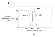
- FIG. 8 is a schematic diagram showing optical transmission characteristics of the polarization selection element 22 .
- the horizontal axis represents the wavelength [nm] of light and the vertical axis represents optical transmittance [%].
- a curve 400 p represents optical transmission characteristic for p-polarized light incident on the polarization selection element 22 .
- the curve 400 p is shown by a dot-dash line.
- a curve 400 s represents optical transmission characteristic for s-polarized light incident on the polarization selection element 22 .
- the curve 400 s is shown by a dotted line.
- the polarization selection element 22 has different optical transmission characteristics for p-polarized light and s-polarized light.
- the characteristics of the polarization selection element 22 when the first monochromatic light sources 20 a and the second monochromatic light sources 20 b are blue laser emitting elements are as shown in FIG. 8 .
- the curve 400 p shows the optical transmittance decreasing from a wavelength of 445 nm (more precisely speaking, near 445 nm), and becoming 0% at a wavelength of 460 nm (more precisely speaking, near 460 nm).
- the curve 400 s shows the optical transmittance decreasing from a wavelength of 430 nm (more precisely speaking, near 430 nm) and becoming 0% at a wavelength of 445 nm (more precisely speaking, near 445 nm).
- the polarization selection element 22 can be used as a polarization selection element for the light in the wavelength band W5 indicated by the double-headed arrow in FIG. 8 .
- the polarization selection element 22 can also be used as a wavelength selection element (a color band filter) for light of wavelengths other than the wavelength band W5 indicated by the double-headed arrow in FIG. 8 .
- the wavelength band W5 is a band from 440 nm to 450 nm.
- the optical transmittance of p-polarized light is 90% or more and the reflectance of s-polarized light is 90% or more. Characteristics at wavelengths less than 440 nm do not matter. For example, at 425 nm, the optical transmittance of p-polarized light may be 60% and the reflectance of s-polarized light may be 30%. What matters here is the optical transmittance and reflectance characteristics for polarized light in the range from 440 nm to 450 nm, in which the polarization selection function is used.
- the polarization selection element 22 has the property of reflecting light with wavelengths longer than 460 [nm]. This example assumes that the center wavelengths of the first monochromatic light sources 20 a and the second monochromatic light sources 20 b are 445 [nm]. However, the center wavelengths may be 465 [nm]. In this case, it suffices for the curve 400 p of the polarization selection element 22 to be transmissive below 470 nm and the curve 400 s to be transmissive below 460 nm. The light with a wavelength of 465 [nm] only has to excite the first phosphor layer 26 a to output red light.
- the light with a wavelength of 465 [nm] only has to excite the second phosphor layer 26 b to output green light.
- the colors excited here by the first phosphor layer 26 a and the second phosphor layer 26 b are determined by the properties of the polarization selection element 22 .
- the polarization selection element 22 is formed with a multilayer dielectric film having the properties of a color separation filter.
- the polarization selection element 22 is a flat plate-shaped element. The case in which the first monochromatic light sources 20 a output p-polarized light and the second monochromatic light sources 20 b output s-polarized light is shown.
- the characteristics of the polarization selection and wavelength selection element 24 are the same as the characteristics of the polarization selection and wavelength selection element 14 in the first embodiment.
- the polarization selection and wavelength selection element 24 has the optical transmission characteristics with respect to wavelength similar to those in FIG. 4 or 6 .
- FIG. 4 shows a characteristic for the case in which the first phosphor layer 26 a outputs light in a red wavelength band. It also shows a characteristic for the case in which the second phosphor layer 26 b outputs light in a green wavelength band.
- FIG. 6 shows a characteristic for the case in which the first phosphor layer 26 a outputs light in a green wavelength band. It also shows a characteristic for the case in which the second phosphor layer 26 b outputs light in a red wavelength band.
- the polarized components of the first polarized light output from the first monochromatic light sources 20 a and the second polarized light output from the second monochromatic light sources 20 b are not 100% polarized.
- the first polarized light includes polarized light with slightly different polarization components.
- the second polarized light also includes polarized light with slightly different polarization components. The second embodiment enables the polarization selection and wavelength selection element 24 to reject the light of s-polarized components incident from the first monochromatic light sources 20 a .
- the polarization selection and wavelength selection element 24 can also reject the light of p-polarized components incident from the second monochromatic light sources 20 b .
- the polarization selection element 22 can reject the light of s-polarized components incident from the first monochromatic light sources 20 a .
- the polarization selection element 22 can reject the light of p-polarized components incident from the second monochromatic light sources 20 b.
- the polarization selection element 22 when only the first monochromatic light sources 20 a are lit, for example, light of s-polarized components in the light output from the first monochromatic light sources 20 a is reflected by the polarization selection element 22 . This eliminates light of s-polarized components directed toward the second phosphor layer 26 b from the light output from the first monochromatic light sources 20 a . Consequently the second phosphor layer 26 b (green phosphor) does not radiate light, which can prevent mixing of the colors red and green.
- the second embodiment also enables more space to be provided between the first monochromatic light sources 20 a and the second monochromatic light sources 20 b than in the first embodiment.
- the light sources in light source devices are heat generating elements. By providing more space between the first monochromatic light sources 20 a and the second monochromatic light sources 20 b , the concentration of these heat generating elements is reduced, which enables the heat to dissipate more easily. This improves the light output efficiency of the first monochromatic light sources 20 a and second monochromatic light sources 20 b .
- the cooling structure for the light sources can also be simplified. In addition, the light source device can be smaller.
- the polarization selection element 22 and the polarization selection and wavelength selection element 24 are given equivalent optical transmission characteristics (the characteristics in FIG. 4 or 6 ), it is also possible to prevent color mixing caused by less than 100% polarization of the polarized components of the first polarized light and the polarized components of the second polarized light.
- the first polarized light is light output from the first monochromatic light sources 20 a .
- the second polarized light is light output from the second monochromatic light sources 20 b . Accordingly, by giving the polarization selection element 22 and the polarization selection and wavelength selection element 24 equivalent optical transmission characteristics, color mixing can be prevented.
- the polarization selection element 22 and the polarization selection and wavelength selection element 24 can be processed in the same lot.
- the second embodiment also produces the effect of preventing color mixing caused by variations of ⁇ 5 nm or more from 445 nm in the center wavelengths of the first monochromatic light sources 20 a and the second monochromatic light sources 20 b.
- the polarization selection element 22 transmits one of the first polarized light and the second polarized light and reflects the other, thereby aiming the direction of propagation of the first polarized light and the direction of propagation of the second polarized light toward the polarization selection and wavelength selection element 24 .
- optical transmission characteristics indicating variations in the optical transmittance with respect to wavelength of the polarization selection and wavelength selection element 24 and the optical transmission characteristics indicating variations in the optical transmittance with respect to wavelength of the polarization selection element 22 are the same. Provided it has a polarization selection characteristic, however, the polarization selection element 22 can be effective in preventing color mixing even if it does not have the same characteristics as the polarization selection and wavelength selection element 24 .
- FIG. 9 is a diagram schematically illustrating a configuration of a projection display device 3 including a light source device 6 according to a third embodiment.
- FIG. 9 shows an orthogonal XYZ coordinate system.
- the X-axis direction is the vertical direction in FIG. 9 .
- the down-to-up direction in FIG. 9 is the positive X-axis direction; the up-to-down direction is the negative X-axis direction.
- a lens group 33 , a light reflecting element 32 , first collimating lenses 31 a , second collimating lenses 31 b , first monochromatic light sources 30 a , and second monochromatic light sources 30 b are disposed on the positive X-axis side of a polarization selection and wavelength selection element 34 .
- the Y-axis direction is the direction perpendicular to the drawing sheet on which FIG. 9 is depicted.
- the positive Y-axis direction is the direction from the reverse side (back side) to the front side of the drawing sheet; the negative Y-axis direction is the direction from the front side to the reverse side (back side) of the drawing sheet.
- the Z-axis direction is the horizontal direction in FIG. 9 .
- the left-to-right direction in FIG. 9 is the positive Z-axis direction; the right-to-left direction is the negative Z-axis direction.
- a color separation element 39 , a focusing lens 71 , a light intensity uniformization element 72 , a relay lens group 73 , an image display element 74 , projection optics 75 , and a screen 76 are disposed on the positive Z-axis side of the polarization selection and wavelength selection element 34 .
- the light source device 6 in the third embodiment differs from the light source device 4 in the first embodiment in that it further includes a lens array group 80 and a lens 81 .
- FIG. 9 components that are the same as components shown in FIG. 1 (in the first embodiment) are given the same reference characters and descriptions are omitted.
- the components that are the same as components in the first embodiment are the focusing lens 71 , the light intensity uniformization element 72 , the relay lens group 73 , image display element 74 , the projection optics 75 , and the screen 76 .
- the components in the third embodiment that are shown with reference characters differing from those used in the first embodiment but whose configurations and functions are the same as those of the components in the first embodiment are the first monochromatic light sources 30 a , the second monochromatic light sources 30 b , the first collimating lenses 31 a , the second collimating lenses 31 b , the first monochromatic light source group 3000 a , the second monochromatic light source group 3000 b , the lens group 33 , the polarization selection and wavelength selection element 34 , a first focusing lens group 35 a , a second focusing lens group 35 b , a first phosphor layer 36 a , a second phosphor layer 36 b , third monochromatic light sources 37 a , 37 b , third collimating lenses 38 a , 38 b , and the color separation element 39 .
- the projection display device 3 includes the light source device 6 , the light intensity uniformization element 72 , the image display element or the light valve 74 , and the projection optics 75 as shown in FIG. 9 .
- the projection display device 3 may also include the focusing lens 71 , the relay lens group 73 , and the screen 76 .
- the light source device 6 according to the third embodiment includes the first monochromatic light source group 3000 a , the second monochromatic light source group 3000 b , the polarization selection and wavelength selection element 34 , the first phosphor layer 36 a , the second phosphor layer 36 b , and the lens array group 80 as shown in FIG. 9 .
- the light source device 6 in the third embodiment may also include a first collimating lens group 3100 a , a second collimating lens group 3100 b , the light reflecting element 32 , the first focusing lens group 35 a , the second focusing lens group 35 b , and the lens 81 .
- the light source device 6 in the third embodiment may include the third monochromatic light sources 37 a , 37 b , the third collimating lenses 38 a , 38 b , and the color separation element 39 , as shown in FIG. 9 .
- the light source device 6 is the same as the light source device 4 in the first embodiment.
- Light fluxes output from the first monochromatic light sources 30 a and the second monochromatic light sources 30 b are reflected by the light reflecting element 32 and their diameters are reduced by the lens group 33 .
- the light fluxes output from the first monochromatic light sources 30 a are focused through the lens array group 80 , the lens 81 , and the first focusing lens group 35 a into a specific shape on the first phosphor layer 36 a .
- the light fluxes output from the second monochromatic light sources 30 b are focused through the lens array group 80 , the lens 81 , and the second focusing lens group 35 b into a specific shape on the second phosphor layer 36 b.
- FIGS. 10( a ) and 10( b ) are schematic frontal views illustrating a first lens array 80 a and a second lens array 80 b .
- FIG. 10( a ) shows the first lens array 80 a .
- FIG. 10( b ) shows the second lens array 80 b .
- the lens array group 80 includes the first lens array 80 a and the second lens array 80 b .
- the first lens array 80 a includes a plurality of lens cells 80 a 1 arrayed in the horizontal and vertical directions.
- the second lens array 80 b includes a plurality of lens cells 80 b 1 arrayed in the horizontal and vertical directions.
- the ‘horizontal and vertical directions’ here denote the directions of mutually orthogonal axes on a plane.
- the shapes of the lens cells 80 a 1 and 80 b 1 are not particularly limited.
- the shapes of the lens cells 80 a 1 and 80 b 1 are, however, preferably similar to the shape of the incidence surface 72 a of the light intensity uniformization element 72 .
- the shape of the lens cells 80 a 1 in the first lens array 80 a is focused onto the first phosphor layer 36 a and second phosphor layer 36 b . That is, the incidence surface of the first lens array 80 a is in an optically conjugate relation with the first phosphor layer 36 a .
- the incidence surface of the first lens array 80 a is also in an optically conjugate relation with the second phosphor layer 36 b .
- An ‘optically conjugate relation’ is a relationship in which light emitted from one point forms an image at the other point.
- the lens cells 80 a 1 and 80 b 1 in FIGS. 10( a ) and 10( b ) are square in shape.
- the shapes of the lens cells 80 a 1 and 80 b 1 are preferably generally similar to the shape of the light valve 74 .
- the shape of the incidence surface of the first lens array 80 a is preferably similar to the shape of the incidence surface 72 a of the light intensity uniformization element 72 .
- the lens array group 80 has the effect of reducing the density of the light fluxes focused onto the first phosphor layer 36 a and the second phosphor layer 36 b .
- the efficiency (external quantum efficiency) of the excitation light on the first phosphor layer 36 a and the second phosphor layer 36 b is degraded by the influence of local increases in temperature. Therefore, it is preferable to focus the light as evenly as possible to uniformize the temperature distribution, thereby improving the external quantum efficiency.
- a means such as a light diffusion plate disposed following the lens array group 80 to reduce the focused density on the first phosphor layer 36 a and the second phosphor layer 36 b .
- a light diffusion plate disturbs the polarization direction of the light.
- following denotes the side toward which the light propagates (i.e., the downstream side in the direction of light propagation) from a position through which the light is transmitted.
- preceding denotes the side away from which the light propagates (i.e., the upstream side in the direction of light propagation) from a position through which the light is transmitted.
- the light intensity uniformization element 72 , the relay lens group 73 , the light valve 74 , the projection optics 75 , and the screen 76 are disposed following the focusing lens 71 .
- the light valve 74 , the relay lens group 73 , the light intensity uniformization element 72 , and the focusing lens 71 are disposed preceding the projection optics 75 .
- the use of the lens array group 80 can solve the above problem of the incidence of a light flux of high optical density on the phosphor surfaces.
- the shape of the incidence surface of the first lens array 80 a can be selected to enhance the focusing efficiency of the light focused onto the light intensity uniformization element 72 .
- the lens 81 is preferably disposed following the lens array group 80 .
- the lens 81 suppresses the dispersion of light that has passed through the lens array group 80 , thereby suppressing a reduction in the amount of light reaching the first focusing lens group 35 a or the second focusing lens group 35 b . This enables light to be focused efficiently onto the first phosphor layer 36 a and the second phosphor layer 36 b.
- the light flux preceding the lens array group 80 is preferably collimated as well as possible. This can efficiently guide the light flux output from the lens array group 80 to the first phosphor layer 36 a and the second phosphor layer 36 b.
- the lens cells 80 a 1 of the first lens array 80 a and the lens cells 80 b 1 of the second lens array 80 b may be mutually eccentric. Making the lens cells 80 a 1 , 80 b 1 eccentric enhances the light focusing efficiency and the uniformity of the light intensity on the first phosphor layer 36 a and the second phosphor layer 36 b.
- the lens 81 is provided in the third embodiment, even if the lens 81 is omitted, it is still possible to focus the light flux into a desired shape on the first phosphor layer 36 a and the second phosphor layer 36 b.
- the first polarized light output from the first monochromatic light sources 30 a reaches the first phosphor layer 36 a .
- the second polarized light output from the second monochromatic light sources 30 b reaches the second phosphor layer 36 b .
- the light output from the third monochromatic light sources 37 a and 37 b is combined with the light excited in the first phosphor layer 36 a and the second phosphor layer 36 b , and reaches the light intensity uniformization element 72 . Accordingly, the amount of red light, the amount of green light, and the amount of blue light can be controlled at the corresponding light sources.
- the light source device and the light sources in the third embodiment can be controlled so as not to emit more light than necessary, thereby lengthening the service life of the light source. It also becomes possible to respond to various color balances in the image to be displayed. That is, in order to display a strongly red image, the individual light sources 30 a , 30 b , 37 a and 37 b can be controlled to increase the optical intensity of red light and reduce the output of green light and blue light.
- the invention in the third embodiment can be used as a light source not only for rear projection television sets, and for frontal projectors and front projection display devices that project images onto a wall or a screen, but also for in-vehicle display devices and other applications.
- the inventions according to the first, second, fourth, and fifth embodiments can also be used as light sources not only for rear projection television sets, and for frontal projectors and front projection display devices that project images onto a wall or a screen, but also for in-vehicle display devices and other applications.
- Another wavelength selection element having an optical transmission band including both the wavelength band of the first polarized light output from the first monochromatic light source group 3000 a and the wavelength band of the second polarized light output from the second monochromatic light source group 3000 b may also be provided.
- This wavelength selection element is disposed on the light path from the first monochromatic light source group 3000 a and the second monochromatic light source group 3000 b to the polarization selection and wavelength selection element 34 .
- the light source device 6 includes the first lens array 80 a including the array of the lens cells 80 a 1 and the second lens array 80 b including the array of the lens cells 80 b 1 , and has the lens array group 80 with the first lens array 80 a and the second lens array 80 b arranged facing each other.
- the first lens array 80 a is disposed on the common light path shared by the light path of the first polarized light from the first monochromatic light source group 3000 a to the polarization selection and wavelength selection element 34 and the light path of the second polarized light from the second monochromatic light source group 3000 b to the polarization selection and wavelength selection element 34 , and the incidence surface of the first lens array 80 a is in an optically conjugate relation with the first phosphor layer 36 a and the second phosphor layer 36 b.
- FIG. 11 is a diagram schematically illustrating a configuration of a projection display device 8 including a light source device 7 according to a fourth embodiment of the invention.
- FIG. 11 shows an orthogonal XYZ coordinate system.
- the X-axis direction is the vertical direction in FIG. 11 .
- the down-to-up direction in FIG. 1 is the positive X-axis direction; the up-to-down direction is the negative X-axis direction.
- Wavelength selection elements 44 and 54 , a lens group 13 , first collimating lenses 11 a , second collimating lenses 11 b , first monochromatic light sources 10 a , and second monochromatic light sources 10 b are disposed on the positive X-axis side of a polarization selection and wavelength selection element 14 .
- the Y-axis direction is the direction perpendicular to the drawing sheet on which FIG. 7 is depicted.
- the positive Y-axis direction is the direction from the reverse side (back side) to the front side of the drawing sheet; the negative Y-axis direction is the direction from the front side to the reverse side (back side) of the drawing sheet.
- the Z-axis direction is the horizontal direction in FIG. 11 .
- the left-to-right direction in FIG. 11 is the positive Z-axis direction; the right-to-left direction is the negative Z-axis direction.
- a color separation element 19 , a focusing lens 71 , a light intensity uniformization element 72 , a relay lens group 73 , an image display element 74 , projection optics 75 , and a screen 76 are disposed on the positive Z-axis side of the polarization selection and wavelength selection element 14 .
- the light source device 7 in the fourth embodiment differs from the light source device 4 in the first embodiment in that it includes the wavelength selection elements 44 and 54 .
- the light source device 7 in the fourth embodiment further differs from the light source device 4 in the first embodiment in that it does not include a light reflecting element 12 .
- FIG. 11 components that are the same as components shown in FIG. 1 (in the first embodiment) are given the same reference characters and descriptions are omitted.
- a center wavelength of the first monochromatic light source group 1000 a and a center wavelength of the second monochromatic light source group 1000 b deviate from their design value (in the range from 440 nm to 450 nm)
- a portion of first polarized light output from the first monochromatic light source group 1000 a is reflected by the polarization selection and wavelength selection element 14 and reaches the second phosphor layer 16 b .
- a portion of second polarized light output from the second monochromatic light source group 1000 b is transmitted through the polarization selection and wavelength selection element 14 and reaches the first phosphor layer 16 a .
- color mixing occurs.
- the fourth embodiment will be described on the assumption that the design value of the center wavelength of the first monochromatic light source group 1000 a and the center wavelength of the second monochromatic light source group 1000 b is 445 nm.
- the wavelength selection elements 44 and 54 that transmit light with wavelengths near 445 nm in the range from 440 nm to 450 nm
- the aforementioned color mixing can be suppressed.
- color mixing due to deviation in the polarization direction of light was dealt with in the second embodiment
- color mixing due to deviation in the wavelength of light will be dealt with in the fourth embodiment.
- the fourth embodiment can prevent color mixing due to deviation of the wavelength of light.
- the fourth embodiment also makes a distance from the first monochromatic light sources 10 a and the second monochromatic light sources 10 b to the lens group 13 shorter than in the first embodiment. This shortens the dimension of the light source device 4 in the X-axis direction, so the light source device 4 can be made more compact.
- the wavelength selection elements 44 and 54 in FIG. 11 are disposed between the lens group 13 and the polarization selection and wavelength selection element 14 .
- the wavelength selection element 44 is disposed on the side nearer the lens group 13 (in the positive X-axis direction); the wavelength selection element 54 is disposed on the side nearer the polarization selection and wavelength selection element 14 (in the negative X-axis direction).
- a light diffusion element 64 is disposed between the lens group 13 and the wavelength selection element 44 .
- the fourth embodiment will be described for the case in which the polarization selection and wavelength selection element 14 has the optical transmission characteristics shown in FIG. 4 .
- the center wavelength of the second monochromatic light source group 1000 b is 450 nm or more, a portion of s-polarized light in the second polarized light is transmitted through the polarization selection and wavelength selection element 14 and reaches the first phosphor layer 16 a .
- the center wavelength of the first monochromatic light source group 1000 a is 440 nm or less, a portion of p-polarized light in the first polarized light is reflected by the polarization selection and wavelength selection element 14 and reaches the second phosphor layer 16 b .
- the center wavelengths of the first monochromatic light source group 1000 a and the second monochromatic light source group 1000 b deviate from the vicinity of 445 nm (within the range from 440 nm to 450 nm) to a short wave side or long wave side, color mixing occurs. Therefore, it is preferable to place the wavelength selection elements 44 , 54 that transmit only light of wavelengths near 445 nm between the light sources 10 a , 10 b and the polarization selection and wavelength selection element 14 .
- the polarization selection and wavelength selection element 14 has different optical transmission characteristics for p-polarized light and s-polarized light.
- the optical transmission characteristics of p-polarized light and the optical transmission characteristics of s-polarized light therefore show different features.
- p-polarized light and s-polarized light show the same optical transmission characteristics. That is, the polarization selection and wavelength selection element 14 has the property of losing its polarization selection function when light enters the polarization selection and wavelength selection element 14 at an incident angle of 0 degrees.
- FIG. 12 is a diagram illustrating p-polarized light and s-polarized light.
- FIG. 12 is a diagram illustrating a reference plane of a polarization axis (polarization direction).
- the reference plane 121 is a plane that includes an optical axis (indicated by a right-pointing arrow in FIG. 12 ) of a light ray 1200 incident on a reflecting element 120 and an optical axis (indicating by an upward-pointing arrow in FIG. 12 ) of the light ray 1200 reflected by the reflecting element 120 .
- Light with a polarization axis parallel to the reference plane 121 is p-polarized light; light with a polarization axis orthogonal to the reference plane 121 is s-polarized light.
- the wavelength selection elements 44 and 54 show the same optical transmission characteristics for both p-polarized light and s-polarized light, as mentioned above.
- the p-s polarization separation width e.g., the width of the wavelength band W1 and the width of the wavelength band W2 in FIG. 4
- the p-s separation width e.g., the width of the wavelength band W1 and the width of the wavelength band W2 in FIG. 4
- FIGS. 13( a ) and 13( b ) are schematic diagrams showing wavelength separation characteristics (optical transmission characteristics) of the wavelength selection elements 44 and 54 .
- the vertical axis represents optical transmittance [%] and the horizontal axis represents wavelength [nm] of light.
- FIG. 13( a ) shows the optical transmission characteristic of the wavelength selection element 44 ;
- FIG. 13( b ) shows the optical transmission characteristic of the wavelength selection element 54 .
- the wavelength selection element 44 reflects light with wavelengths of 450 nm or more. That is, the wavelength selection element 44 reflects light on the long wavelength side of 450 nm.
- a transmittance curve 130 a indicating the optical transmission characteristic of the wavelength selection element 44 may be shifted toward the short wavelength side of 450 nm.
- the wavelength selection element 54 reflects light having wavelengths of 440 nm or less. That is, wavelength selection element 54 reflects light on the short wavelength side of 440 nm.
- a transmittance curve 130 b indicating the optical transmission characteristic of the wavelength selection element 54 may be shifted toward the long wavelength side of 440 nm.
- FIG. 14 is a schematic diagram showing the wavelength separation characteristic when a single element is employed as the wavelength selection elements 44 and 54 .
- the vertical axis represents optical transmittance [%] and the horizontal axis represents wavelength [nm] of light.
- the optical transmission characteristic shown in FIG. 14 is a characteristic that transmits light in the wavelength range from 440 nm to 450 nm.
- the wavelength selection elements 44 , 54 have the property of transmitting light with wavelengths in the range from 440 nm to 450 nm. For this reason, the wavelength selection elements can be combined into a single element if it provides an incidence surface having the optical transmission characteristic of the wavelength selection element 44 and an output surface having the characteristic of the wavelength selection element 54 .
- the single wavelength selection element configuration allows the light source device 7 to be more compact.
- the wavelength of the light that passes through the wavelength selection element 44 and the wavelength selection element 54 may be within the range from 440 nm to 450 nm. Accordingly, the wavelength characteristics of the wavelength selection elements 44 , 54 for wavelengths deviating greatly from 440 nm and 450 nm are immaterial.
- the wavelength selection element 44 is shown as having the property of reflecting light on the long wavelength side of 450 nm (optical transmittance is 0%) and the property of transmitting light on the short wavelength side of 450 nm (optical transmittance is 100%).
- the wavelength selection element 44 however may have the property of reflecting light with a wavelength of 400 nm, which deviates greatly from 440 nm and 450 nm.
- the light diffusion element 64 may be provided between the first monochromatic light source group 1000 a and the wavelength selection elements 44 , 54 .
- the light diffusion element 64 may also be provided between the second monochromatic light source group 1000 b and the wavelength selection elements 44 , 54 .
- the light diffusion element 64 has the function of varying an angle of light. This enables a reduction of the intensity of light returning directly to the first monochromatic light source group 1000 a and the second monochromatic light source group 1000 b .
- the light diffusion element 64 may be disposed at any position as long as it is between the first monochromatic light source group 1000 a and the second monochromatic light source group 1000 b and the wavelength selection elements 44 , 54 .
- the light diffusion element 64 may be disposed in the lens group 13 . If the light diffusion element 64 has low light diffusivity, it has little effect on the degree of polarization of the light.
- color mixing due to variations in the degree of polarization of the monochromatic light source groups 1000 a , 1000 b is not taken into consideration.
- the configuration in the second embodiment is preferable.
- the fourth embodiment can be considered preferable, however, from the viewpoints of reducing the size and manufacturing cost of the light source device.
- a portion of the red light output from the first phosphor layer 16 a is transmitted through the polarization selection and wavelength selection element 14 .
- a portion of the green light output from the second phosphor layer 16 b is reflected by the polarization selection and wavelength selection element 14 .
- a portion of the light output from the first phosphor layer 16 a and the second phosphor layer 16 b is thereby returned to the monochromatic light source groups 1000 a , 1000 b.
- FIG. 15 is a schematic diagram showing an example of relative light intensity with respect to wavelength (a curve 200 G) of the light excited in the phosphor layer for the color green.
- FIG. 15 is also a diagram showing an example of relative light intensity with respect to wavelength (a curve 200 R) of the light excited in the phosphor layer for the color red.
- the vertical axis on the right side of FIG. 15 represents relative light intensity [%].
- the vertical axis on the left side of FIG. 15 represents optical transmittance [%].
- the horizontal axis in FIG. 15 represents wavelength [nm].
- a curve 200 p represents optical transmission characteristic of p-polarized light incident on the polarization selection and wavelength selection element 14 .
- the curve 200 p is shown by a dot-dash line.
- a curve 200 s represents optical transmission characteristic of s-polarized light incident on the polarization selection and wavelength selection element 14 .
- the curve 200 s is shown by a dashed line with short dashes.
- the curve 200 G represents green excited light.
- the curve 200 G is shown by a dashed line with long dashes.
- a center wavelength of the curve 200 G is 550 nm.
- the green excited light has a non-uniform polarization direction.
- a portion of light of s-polarized components on the long wavelength side of 575 nm is reflected by the polarization selection and wavelength selection element 14 and returns to the monochromatic light source groups 1000 a , 1000 b .
- the curve 200 R represents red excited light.
- the curve 200 R is shown by a dash-dot-dot line.
- a center wavelength of the curve 200 R is 620 nm.
- the red excited light also has a non-uniform polarization direction.
- a portion of light of p-polarized components on the short wavelength side of 610 nm is transmitted by the polarization selection and wavelength selection element 14 and returns to the monochromatic light source groups 1000 a , 1000 b.
- the wavelength selection elements 44 , 54 reflect light on the long wavelength side of 450 nm. Accordingly, they have the further effect of reducing the return of light from the first phosphor layer 16 a and the second phosphor layer 16 b.
- the additional wavelength selection elements 44 and 54 have an optical transmission band that includes both the wavelength band of the first polarized light output from the first monochromatic light source group 1000 a and the wavelength band of the second polarized light output from the second monochromatic light source group 1000 b .
- the wavelength selection elements 44 and 54 are disposed on the light path from the first monochromatic light source group 1000 a and the second monochromatic light source group 1000 b to the polarization selection and wavelength selection element 14 .
- a center wavelength of the light emitted from the first monochromatic light source group 1000 a is 465 nm.
- the light emitted from the second monochromatic light source group 1000 b is s-polarized light with a center wavelength of 445 nm.
- the light emitted from the first monochromatic light source group 1000 a is transmitted through the polarization selection and wavelength selection element 14 and reaches the first phosphor layer 16 a , thereby exciting it to generate red light.
- the polarization direction of the light emitted from the first monochromatic light source group 1000 a does not matter.
- the second monochromatic light source group 1000 b emits the s-polarized light with the center wavelength of 445 nm.
- the light emitted from the second monochromatic light source group 1000 b is reflected by the polarization selection and wavelength selection element 14 and reaches the second phosphor layer 16 b , thereby exciting it to generate green light.
- the light emitted from the first monochromatic light source group 1000 a is p-polarized light with a center wavelength of 445 nm.
- a center wavelength of the light emitted from the second monochromatic light source group 1000 b is 465 nm.
- the light emitted from the first monochromatic light source group 1000 a is transmitted through the polarization selection and wavelength selection element 14 and reaches the first phosphor layer 16 a , where it generates green excited light.
- the light emitted from the second monochromatic light source group 1000 b is reflected by the polarization selection and wavelength selection element 14 and reaches the second phosphor layer 16 b , where it generates red excited light.
- the polarization direction of the light emitted from the second monochromatic light source group 1000 b does not matter.
- the difference between the (half value) position of 50% optical transmittance of p-polarized light on the short wavelength side and the position of 50% optical transmittance of s-polarized light on the short wavelength side ranges from about 10 nm to 20 nm. Accordingly, when the difference between the center wavelength of the first monochromatic light source group 1000 a and the center wavelength of the second monochromatic light source group 1000 b is 20 nm or less, the monochromatic light sources on the short wavelength side become capable of making light reach the phosphor layer by use of polarization characteristics, thereby increasing the efficiency of the light.
- the polarization direction of the monochromatic light source group with the center wavelength of 465 nm need not be orthogonal or parallel to the polarization axis of the polarization selection and wavelength selection element 14 . More precisely speaking, it is not necessary for a majority of the components to be orthogonal or parallel to the polarization axis. For example, a rotational polarization direction (circular polarization) is allowable.
- the first variation of the fourth embodiment presents a configuration of the light source device 7 in which light emitted from the first monochromatic light source group 1000 a is p-polarized light with a center wavelength of 445 nm and a center wavelength of light emitted from the second monochromatic light source group 1000 b is 465 nm.
- This configuration is applicable to the first, second, or third embodiment. In such cases, it suffices for the polarization selection and wavelength selection element 14 to have the optical transmission characteristics shown in FIG. 6 . This enables the occurrence of color mixing to be suppressed without the need to consider the polarization direction of the second monochromatic light source group 1000 b.
- the first variation of the fourth embodiment also presents a configuration of the light source device 7 in which a center wavelength of the light emitted from the first monochromatic light source group 1000 a is 465 nm and the light emitted from the second monochromatic light source group 1000 b is s-polarized light with a center wavelength of 445 nm.
- This type of configuration is applicable to the first, second, or third embodiment. In this case, it suffices for the polarization selection and wavelength selection element 14 to have the optical transmission characteristics shown in FIG. 4 .
- the difference between the center wavelengths of the first monochromatic light source group 1000 a and the second monochromatic light source group 1000 b is greater than 20 nm, it is possible to use only the function of the polarization selection and wavelength selection element 14 as a wavelength selection element to maintain a high light utilization efficiency while suppressing the occurrence of color mixing.
- the center wavelength of the second polarized light differs from the center wavelength of the first polarized light.
- the first polarized light is light output by the first monochromatic light sources 10 a .
- the second polarized light is light output by the second monochromatic light sources 10 b.
- the optical transmission band of the wavelength selection elements 44 , 54 includes the wavelength band of the first polarized light output from the first monochromatic light source group 1000 a and the wavelength band of the second polarized light output from the second monochromatic light source group 1000 b . Accordingly, when the center wavelength of the light emitted from the first monochromatic light source group 1000 a is 445 nm and the center wavelength of the light emitted from the second monochromatic light source group 1000 b is 465 nm, it suffices for the wavelength of light that has passed through the wavelength selection element 44 and the wavelength selection element 54 to be within the range from 440 nm to 470 nm.
- the wavelength selection elements 44 , 54 thereby reflect light on the long wavelength side of 470 nm. Accordingly, they have the further effect of suppressing the return of light from the first phosphor layer 16 a and the second phosphor layer 16 b.
- FIG. 16 is a diagram schematically illustrating a configuration of a projection display device 9 a in a second variation of the fourth embodiment.
- the projection display device 9 a according to the second variation differs from the projection display device 8 shown in FIG. 11 in that it includes third monochromatic light sources 47 a and 47 b , third collimating lenses 48 a and 48 b , and a color separation element (light path alteration element) 49 instead of the third monochromatic light sources 17 a and 17 b , the third collimating lenses 18 a and 18 b , and the color separation element 19 .
- the third monochromatic light sources 47 a and 47 b constitute a third monochromatic light source group 4700 .
- the projection display device 9 a in the second variation also differs from the projection display device 8 in FIG. 11 , in which the color separation element 19 is disposed between the polarization selection and wavelength selection element 14 and the focusing lens 71 , in that the color separation element 49 is disposed between the focusing lens 71 and the light intensity uniformization element 72 .
- the third monochromatic light sources 47 a and 47 b are disposed so as to emit a light flux in the negative X-axis direction.
- the third collimating lenses 48 a and 48 b are disposed in the negative X-axis direction from the third monochromatic light sources 47 a and 47 b .
- the third collimating lenses 48 a and 48 b collimate the light emitted from the third monochromatic light sources 47 a and 47 b .
- a focusing lens 300 is disposed in the negative X-axis direction from the third monochromatic light sources 47 a and 47 b .
- the focusing lens 300 focuses the light emitted from the third monochromatic light sources 47 a and 47 b onto the incidence surface 72 a of the light intensity uniformization element 72 .
- the light flux may be directed onto the light intensity uniformization element 72 without use of the focusing lens 300 , by making the optical axes of the third collimating lenses 48 a and 48 b eccentric with respect to the optical axes of the third monochromatic light sources 47 a and 47 b .
- the color separation element 49 is disposed in the negative X-axis direction from the focusing lens 300 .
- the third monochromatic light source group 4700 outputs light in a third wavelength band.
- the color separation element (light path alteration element) 49 brings the light path of the light in the third wavelength band into coincidence with the common light path shared by the light path of the light in the first wavelength band that has been reflected by the polarization selection and wavelength selection element 14 and the light path of the light in the second wavelength band that has been transmitted through the polarization selection and wavelength selection element 14 .
- a light source device 7 a uses the focusing lens 71 to focus light in the first wavelength band reflected by the polarization selection and wavelength selection element 14 and light in the second wavelength band transmitted through the polarization selection and wavelength selection element 14 onto the light intensity uniformization element 72 .
- the light path altering element 49 is disposed between the focusing lens 71 and the light intensity uniformization element 72 , in place of the color separation element 19 .
- Light fluxes output from the first phosphor layer 16 a and the second phosphor layer 16 b are focused onto the light intensity uniformization element 72 through the focusing lens 71 .
- Light fluxes emitted from the third monochromatic light sources 47 a and 47 b are focused onto the light intensity uniformization element 72 via the color separation element 49 . Therefore, the light emitted from the third monochromatic light sources 47 a and 47 b takes a light path differing and independent from that of the light entering the light intensity uniformization element 72 from the polarization selection and wavelength selection element 14 . This enables a space between the polarization selection and wavelength selection element 14 and the focusing lens 71 to be reduced. The length in the Z-axis direction is therefore shortened, enabling the device to be more compact.
- the color separation element 49 has the property of reflecting the light flux in the wavelength band of the third monochromatic light sources 47 a and 47 b and transmitting the light that enters the light intensity uniformization element 72 from the polarization selection and wavelength selection element 14
- the configuration of the third monochromatic light sources 47 a and 47 b , the third collimating lenses 48 a and 48 b , and the color separation element 49 shown in the second variation can be employed in embodiments other than those described above.
- the projection display device 1 in the first embodiment shown in FIG. 1 can employ the configuration of the third monochromatic light sources 47 a and 47 b , the third collimating lenses 48 a and 48 b , and the color separation element 49 described in the second variation instead of the third monochromatic light sources 17 a and 17 b , the third collimating lenses 18 a and 18 b , and the color separation element 19 .
- the projection display device 3 in the third embodiment shown in FIG. 9 can employ the configuration described in the second variation instead of the third monochromatic light sources 37 a and 37 b , the third collimating lenses 38 a and 38 b , and the color separation element 39 .
- the light source device 7 a includes the third monochromatic light source group 4700 and the light path altering element 49 .
- the third monochromatic light source group 4700 outputs light in the third wavelength band.
- the light path altering element 49 brings the light path of the light in the third wavelength band into coincidence with the common light path shared by the light path of light in the first wavelength band that has been reflected by the polarization selection and wavelength selection element 14 and the light path of light in the second wavelength band that has been transmitted through the polarization selection and wavelength selection element 14 .
- the light source device 7 a includes the focusing lens 71 for focusing light in the first wavelength band reflected by the polarization selection and wavelength selection element 14 and light in the second wavelength band transmitted through the polarization selection and wavelength selection element 14 onto the light intensity uniformization element 72 .
- the light path altering element 49 is disposed between the focusing lens 71 and the light intensity uniformization element 72 .
- FIG. 17 is a diagram schematically illustrating a configuration of a projection display device 9 b in a third variation of the fourth embodiment.
- the projection display device 9 b in the third variation of the fourth embodiment employs a third phosphor layer 56 c instead of the blue laser light sources 17 a and 17 b .
- the projection display device 9 b according to the third variation differs from the projection display device 8 shown in FIG.
- third monochromatic light sources 57 third collimating lenses 58 , a lens group 53 , a color separation element (light path alteration element) 59 , a third focusing lens group 55 c , and the third phosphor layer 56 c instead of the third monochromatic light sources 17 a and 17 b , the third collimating lenses 18 a and 18 b , and the color separation element 19 in the projection display device 8 shown in FIG. 11 .
- the plurality of third monochromatic light sources 57 constitute a third monochromatic light source group 5700 .
- the third monochromatic light sources 57 are disposed so as to emit light fluxes in the negative X-axis direction.
- a center wavelength of the third monochromatic light sources 57 is, for example, 405 nm.
- the third collimating lenses 58 are disposed in correspondence to the third monochromatic light sources 57 in the negative X-axis direction from the third monochromatic light sources 57 . That is, one third collimating lens 58 is provided per third monochromatic light source 57 .
- the plurality of third collimating lenses 58 constitute a third collimating lens group 5800 .
- the third collimating lenses 58 convert the light fluxes output from the third monochromatic light sources 57 into collimated light.
- the lens group 53 is disposed in the negative X-axis direction from the third collimating lenses 58 . Like the lens group 13 , the lens group 53 has the functions of reducing the diameter of and collimating the light flux emitted from the third monochromatic light source 57 .
- the lens group 53 includes, for example, a first lens and a second lens.
- the configuration of the lens group 53 is not limited to the example shown in FIG. 17 .
- the lens group 53 may have a single-lens configuration.
- the lens group 53 may also be configured with three or more lenses.
- the lens groups 13 and 53 may be omitted from a configuration of a light source device 7 b.
- the color separation element 59 is disposed in the negative X-axis direction from the lens group 53 .
- the light collimated after diameter reduction by the lens group 53 is transmitted through the color separation element 59 and propagates in the negative X-axis direction.
- the characteristics of the color separation element 59 differ from those of the color separation elements 19 , 49 shown in the fourth embodiment.
- the horizontal axis represents wavelength [nm] of light and the vertical axis represents optical transmittance [%].
- a curve 170 s in FIG. 18 shown by a dashed line, represents the optical transmission characteristic of s-polarized light.
- a curve 170 p shown by a dot-dash line, represents the optical transmission characteristic of p-polarized light.
- the color separation element 59 transmits 90% or more of the light in the wavelength band from 400 nm to 410 nm.
- the optical transmission characteristic of the color separation element 59 for s-polarized light starts decreasing from, for example, 410 nm (more precisely speaking, near 410 nm) and becomes 0% at 425 nm (more precisely speaking, near 425 nm).
- the optical transmission characteristic for s-polarized light starts increasing from 490 nm (more precisely speaking, near 490 nm) and becomes 100% at 505 nm (more precisely speaking, near 505 nm).
- the optical transmission characteristic of p-polarized light of the color separation element 59 starts decreasing from 420 nm (more precisely speaking, near 420 nm), and becomes 0% at 435 nm (more precisely speaking, near 435 nm).
- the optical transmission characteristic for p-polarized light starts increasing from 475 nm (more precisely speaking, near 475 nm) and becomes 100% at 490 nm (more precisely speaking, near 490 nm).
- the color separation element 59 to reflect only light in the blue wavelength band from 435 nm to 475 nm. That is, excitation light, which has a center wavelength of 405 nm, light in the green wavelength band, and light in the red wavelength band pass through the color separation element 59 . Light in the blue wavelength band is reflected by the color separation element 59 . It is thereby possible to form white light from phosphor light of the three colors of red, green, and blue. An example in which light in the wavelength band from 435 nm to 475 nm is reflected has been shown, but the color separation element 59 may have the property of reflecting light in, for example, the wavelength band from 450 nm to 480 nm.
- the third focusing lens group 55 c is disposed in the negative X-axis direction from the color separation element 59 .
- the third focusing lens group 55 c in combination with the lens group 53 , for example, focuses light that has been collimated after diameter reduction by the lens group 53 .
- the third focusing lens group 55 c includes a first focusing lens 55 c 1 and a second focusing lens 55 c 2 .
- the first focusing lens 55 c 1 is the lens nearest the third phosphor layer 56 c .
- the second focusing lens 55 c 2 is the lens second nearest the third phosphor layer 56 c .
- the configuration of the third focusing lens group 55 c is not limited to the example shown in FIG. 17 .
- the third focusing lens group 55 c may be configured with a single lens.
- the third focusing lens group 55 c may also be configured with three or more lenses.
- the third phosphor layer 56 c is disposed in the negative X-axis direction from the third focusing lens group 55 c .
- the light focused by the third focusing lens group 55 c enters the third phosphor layer 56 c as excitation light.
- the third phosphor layer 56 c is excited by the light focused by the third focusing lens group 55 c to emit light in the third wavelength band.
- the light in the third wavelength band is, for example, light in the blue wavelength band.
- the light output from the third phosphor layer 56 c may be light in the blue wavelength band with a center wavelength of 460 nm. More precisely speaking, it may be light with a center wavelength near 460 nm.
- the light in the third wavelength band propagates in the positive X-axis direction. After being reflected by the color separation element 59 , the light in the third wavelength band propagates in the positive Z-axis direction. The light in the third wavelength band reflected by the color separation element 59 propagates on the same light path as the common light path shared by the light in the first wavelength band reflected by the polarization selection and wavelength selection element 14 and the light in the second wavelength band transmitted through the polarization selection and wavelength selection element 14 . After that, the light in the third wavelength band is focused onto the light intensity uniformization element 72 by the focusing lens 71 .
- FIG. 19 is a diagram schematically illustrating a configuration of a projection display device 90 including a light source device 7 c according to a fifth embodiment.
- FIG. 9 shows an orthogonal XYZ coordinate system.
- the X-axis direction is the vertical direction in FIG. 19 .
- the down-to-up direction in FIG. 9 is the positive X-axis direction; the up-to-down direction is the negative X-axis direction.
- a lens group 23 , a color separation element 62 , first collimating lenses 21 a , second collimating lenses 21 b , first monochromatic light sources 20 a , and second monochromatic light sources 20 b are disposed on the positive X-axis side of a color separation element 65 .
- the Y-axis direction is the direction perpendicular to the drawing sheet on which FIG. 19 is depicted.
- the positive Y-axis direction is the direction from the reverse side (back side) to the front side of the drawing sheet; the negative Y-axis direction is the direction from the front side to the reverse side (back side) of the drawing sheet.
- the Z-axis direction is the horizontal direction in FIG. 19 .
- the left-to-right direction in FIG. 19 is the positive Z-axis direction; the right-to-left direction is the negative Z-axis direction.
- a color separation element 69 , a focusing lens 71 , a light intensity uniformization element 72 , a relay lens group 73 , an image display element 74 , projection optics 75 , and a screen 76 are disposed on the positive Z-axis side of the color separation element 65 .
- the light source device 7 c according to the fifth embodiment differs from the light source device 5 in the second embodiment in that it uses the color separation element 69 , a third focusing lens group 25 c , and a third phosphor layer 26 c instead of the color separation element 29 , the third collimating lenses 28 a and 28 b , and the third monochromatic light sources 27 a and 27 b , replaces the polarization selection element 22 with the color separation element 62 , and replaces the polarization selection and wavelength selection element 24 with the color separation element 65 .
- the light source device 7 c differs from the light source device 5 in that it further includes third collimating lenses 21 c and third monochromatic light sources 20 c.
- FIG. 19 components that are the same as components shown in FIG. 7 (in the second embodiment) are given the same reference characters and descriptions are omitted.
- the components that are the same as components in the second embodiment are a first monochromatic light source group 2000 a , a second monochromatic light source group 2000 b , a first collimating lens group 2100 a , a second collimating lens group 2100 b , the lens group 23 , a first focusing lens group 25 a , a second focusing lens group 25 b , a first phosphor layer 26 a , a second phosphor layer 26 b , the focusing lens 71 , the light intensity uniformization element 72 , the relay lens group 73 , the image display element 74 , the projection optics 75 , and the screen 76 .
- the second monochromatic light sources 20 b , the second monochromatic light source group 2000 b , the second collimating lenses 21 b , the second collimating lens group 2100 b , the second focusing lens group 25 b , the second phosphor layer 26 b , and the lens group 23 had characteristics adapted for green light when the polarization selection and wavelength selection element 24 in FIG. 4 was used; in the fifth embodiment their characteristics will be described as adapted for blue light. As set forth later, the characteristics of the color separation element 65 differ from the characteristics of the polarization selection and wavelength selection element 24 in FIG. 4 .
- the projection display device 90 includes the light source device 7 c , the light intensity uniformization element 72 , the image display element or the light valve 74 , and the projection optics 75 as shown in FIG. 19 .
- the projection display device 90 may also include the focusing lens 71 , the relay lens group 73 , and the screen 76 .
- the light source device 7 c according to the fifth embodiment includes the first monochromatic light source group 2000 a , the second monochromatic light source group 2000 b , the color separation element 65 , the first phosphor layer 26 a , and the second phosphor layer 26 b as shown in FIG. 19 .
- the light source device 7 c may also include a third monochromatic light source group 2000 c , the color separation element 69 , the third phosphor layer 26 c , and the color separation element 62 .
- the light source device 7 c according to the fifth embodiment may include the first collimating lens group 2100 a , the second collimating lens group 2100 b , a third collimating lens group 2100 c , lens groups 23 and 63 , the first focusing lens group 25 a , the second focusing lens group 25 b , and the third focusing lens group 25 c.
- the third phosphor layer 26 c is disposed at the position of the third monochromatic light sources 27 a and 27 b .
- the third focusing lens group 25 c is disposed at the position of the third collimating lenses 28 a and 28 b.
- the polarization and polarization direction of light emitted from the first monochromatic light sources 20 a , light emitted from the second monochromatic light sources 20 b , and light emitted from the third monochromatic light sources 20 c do not matter. That is, the light output from the first monochromatic light sources 20 a , the light output from the second monochromatic light sources 20 b , and the light output from the third monochromatic light sources 20 c may be s-polarized light, p-polarized light, or elliptically polarized light.
- the first light sources 20 a are excitation light sources with a center wavelength of 460 nm, used for the color red.
- the second light sources 20 b are excitation light sources with a center wavelength of 405 nm, used for the color blue.
- the third light sources 20 c are excitation light sources with a center wavelength of 445 nm, used for the color green.
- the center wavelength of the first light sources 20 a may be 445 nm, but this embodiment will describe the case of 460 nm.
- the color separation element 62 has the function of transmitting the light emitted by the first light sources 20 a with a center wavelength of 460 nm.
- the color separation element 62 also has the function of reflecting the light emitted by the second light sources 20 b with a center wavelength of 405 nm.
- the color separation element 62 has characteristics similar to the characteristics shown in FIG. 4 at wavelengths equal to 500 nm or less. That is, the color separation element 62 has characteristics that reflect light with a center wavelength of 405 nm and transmit light of a center wavelength of 460 nm, regardless of the polarization direction. It may have the same characteristics as in FIG. 4 , but 500 nm or less was mentioned here because it is the characteristics on the short wavelength side that are important.
- the light emitted by the first light sources 20 a is output in the negative X-axis direction.
- the light emitted from the first light sources 20 a is collimated by the first collimating lenses 21 a .
- the light emitted from the first light sources 20 a is transmitted through the color separation element 62 and becomes collimated light with a light flux diameter reduced by the lens group 23 .
- the light emitted from the first light sources 20 a is then transmitted through the color separation element 65 .
- the light flux emitted from the first light sources 20 a is focused onto the first phosphor layer 26 a for the color red by the first focusing lens group 25 a.
- the light emitted by the second light sources 20 b is output in the positive Z-axis direction.
- the light emitted from the second light sources 20 b is collimated by the second collimating lenses 21 b . After that, it is reflected by the color separation element 62 , propagates in the negative X-axis direction, and becomes collimated light with a light flux diameter reduced by the lens group 23 .
- the light emitted from the second light sources 20 b is then reflected in the negative Z-axis direction by the color separation element 65 . After being reflected by the color separation element 65 , the light flux emitted from the second light sources 20 b is focused onto the second phosphor layer 26 b for the color blue by the second focusing lens group 25 b.
- the color separation element 65 has the property of transmitting light in a blue wavelength band and the property of reflecting red light.
- the color separation element 65 displays, for example, the same optical transmission characteristics as in FIG. 4 .
- the term ‘light in a blue wavelength band’ here denotes light with a wavelength from 450 nm to 480 nm.
- the term ‘light in a red wavelength band’ denotes light with a wavelength from 585 nm to 630 nm.
- the term ‘light in a green wavelength band’ denotes light with a wavelength from 500 nm to 580 nm.
- the light emitted from the first phosphor layer 26 a for the color red propagates in the positive X-axis direction, is reflected in the positive Z-axis direction by the color separation element 65 , and propagates toward the color separation element 69 .
- the light emitted from the second phosphor layer 26 b for the color blue propagates in the positive Z-axis direction, passes through the color separation element 65 , and propagates toward the color separation element 69 .
- the light emitted from the first phosphor layer 26 a for the color red and reflected by the color separation element 65 and the light emitted from the second phosphor layer 26 b for the color blue and transmitted through the color separation element 65 propagate on a common light path.
- the color separation element 69 transmits light in the blue wavelength band and light in the red wavelength band.
- the color separation element 69 also reflects light in the green wavelength band.
- FIG. 20 is a diagram illustrating the wavelength selection characteristics of the color separation element 69 .
- the horizontal axis represents wavelength [nm] of light and the vertical axis represents optical transmittance [%].
- a curve 210 s in FIG. 20 shown by a dashed line, represents the optical transmission characteristic for s-polarized light.
- a curve 210 p shown by a dot-dash line, shows the optical transmission characteristic for p-polarized light. For s-polarized light, for example, as shown in FIG.
- the optical transmittance decreases from a wavelength of 465 nm (more precisely speaking, near 465 nm) and becomes 0% at a wavelength of 480 nm (more precisely speaking, near 480 nm).
- the optical transmittance characteristic for s-polarized light also starts increasing from a wavelength of 585 nm (more precisely speaking, near 585 nm) and becomes 100% at a wavelength of 600 nm (more precisely speaking, near 600 nm).
- the optical transmittance decreases from a wavelength of 475 nm (more precisely speaking, near 475 nm) and becomes 0% at a wavelength of 490 nm (more precisely speaking, near 490 nm).
- the optical transmittance for p-polarized light also starts increasing from a wavelength of 570 nm (more precisely speaking, near 570 nm) and becomes 100% at a wavelength of 585 nm (more precisely speaking, near 585 nm).
- Light in the red wavelength band and light in the blue wavelength band pass through the color separation element 69 and proceed toward the focusing lens 71 .
- a light flux in the green wavelength band is emitted from the third phosphor layer 26 c .
- the third phosphor layer 26 c is disposed on the negative X-axis side of the color separation element 69 .
- the excitation light sources of the third phosphor layer 26 c are the third monochromatic light sources 20 c .
- the third monochromatic light sources 20 c are disposed on the positive X-axis side of the color separation element 69 .
- a center wavelength of the third monochromatic light sources 20 c is 445 nm.
- the third monochromatic light sources 20 c output light in the negative X-axis direction.
- the output light is collimated by the third collimating lenses 21 c .
- the flux diameter of the collimated light flux is reduced by a lens group 63 .
- the lens group 63 includes, for example, a first lens and a second lens.
- the configuration of the lens group 63 is not limited to the example shown in FIG. 19 .
- the lens group 63 may be configured with a single lens.
- the lens group 63 may also be configured with three or more lenses.
- the light source device 7 c may be configured without the lens group 63 .
- the collimated light with the reduced flux diameter propagates toward the color separation element 69 .
- the collimated light with the reduced flux diameter is transmitted through the color separation element 69 .
- the collimated light with the reduced light flux diameter is focused by the third focusing lens group 25 c onto the third phosphor layer 26 c for the color green.
- the focused light excites the third phosphor layer 26 c .
- the third phosphor layer 26 c outputs green light in the positive X-axis direction.
- the light in the green wavelength band is collimated by the third focusing lens group 25 c , reflected by the color separation element 69 , and then propagates in the positive Z-axis direction.
- the light in the green wavelength band reflected by the color separation element 69 propagates on the same light path as the light in the red wavelength band reflected by the color separation element 65 and the light in the blue wavelength band transmitted through color separation element 65 . After that, the green light propagates toward the focusing lens 71 .
- the configuration following (on the positive Z-axis side of) the focusing lens 71 is the same as in FIG. 7 , so a description will be omitted.
- the first monochromatic light sources 20 a and the second monochromatic light sources 20 b may be arranged in the same way as the light sources in the first embodiment. In that case, the color separation element 62 is replaced with a light reflecting element (light reflecting mirror) 12 .
- each color can be turned on without temporal constraints.
- the positions of the second phosphor layer 26 b for the color blue and the first phosphor layer 26 a for the color red may be interchanged.
- the color separation element 65 has wavelength characteristics that reflect light emitted from the second monochromatic light sources 20 b for the color red, transmit light emitted from the first monochromatic light sources 20 a for the color blue, reflect light emitted from the first phosphor layer 26 a for the color blue, and transmit light emitted by the second phosphor layer 26 b for the color red. In short, it suffices for the color separation element 65 to have characteristics similar to the characteristics in FIG. 18 .
- the fifth embodiment uses the first light sources 20 a as an excitation light source for the color red and the third light sources 20 c as an excitation light source for the color green. It is also possible, however, to give the first light sources 20 a a center wavelength of 445 nm and use the first light sources 20 a as an excitation light source for the color green.
- the color separation element 62 has the property of reflecting light with a center wavelength of 405 nm and transmitting light with a center wavelength of 445 nm. It suffices for the color separation element 65 to reflect light with a center wavelength of 405 nm, transmit light with a center wavelength of 445 nm, transmit light in the blue wavelength band, and reflect light in the green wavelength band.
- the color separation elements 62 and 65 may have the characteristics shown in FIG. 21 .
- FIG. 21 is a diagram illustrating the wavelength selection characteristics of the color separation element.
- the horizontal axis represents wavelength [nm] of light and the vertical axis represents optical transmittance [%].
- a curve 220 s shown by a dashed line, represents the optical transmission characteristic for s-polarized light.
- a curve 220 p shown by a dot-dash line, represents the optical transmission characteristic for p-polarized light.
- the optical transmittance increases from a wavelength of 425 nm (more precisely speaking, near 425 nm) and becomes 100% at a wavelength of 440 nm (more precisely speaking, near 440 nm).
- the optical transmittance characteristic for s-polarized light also starts decreasing from a wavelength of 470 nm (more precisely speaking, near 470 nm) and becomes 0% at a wavelength of 485 nm (more precisely speaking, near 485 nm).
- the optical transmittance increases from a wavelength of 415 nm (more precisely speaking, near 415 nm) and becomes 100% at a wavelength of 430 nm (more precisely speaking, 430 nm).
- the optical transmittance characteristic for p-polarized light also starts decreasing from a wavelength of 485 nm (more precisely speaking, near 485 nm) and becomes 0% at a wavelength of 500 nm (more precisely speaking, near 500 nm).
- the first phosphor layer 26 a emits green light and the third phosphor layer 26 c emits red light. Accordingly, since the third light sources 20 c become the excitation light source for the color red, it is necessary to take the characteristics of the color separation element 69 into consideration. In this case, the center wavelength of the third light sources 20 c is 445 nm or 460 nm.
- the color separation element 69 must have characteristics such that light in the red wavelength band is reflected and light in the blue and green wavelength bands is transmitted. Accordingly, the color separation element 69 may have the characteristics shown in FIG. 22 .
- FIG. 22 is a diagram illustrating the wavelength selection characteristics of the color separation element.
- the horizontal axis represents wavelength [nm] of light and the vertical axis represents optical transmittance [%].
- a curve 230 s shown by a dashed line, represents the optical transmittance characteristic for s-polarized light.
- a curve 230 p shown by a dot-dash line, represents the optical transmission characteristic for p-polarized light.
- the optical transmittance characteristic for s-polarized light starts decreasing from a wavelength of 570 nm (more precisely speaking, near 570 nm) and becomes 0% at a wavelength of 585 nm (more precisely speaking, near 585 nm).
- the optical transmittance characteristic for p-polarized light starts decreasing from a wavelength of 585 nm (more precisely speaking, near 585 nm) and becomes 0% at a wavelength of 600 nm (more precisely speaking, near 600 nm). This enables the color separation element 69 to reflect only light in the red wavelength band.
- the difference between the center wavelength of 405 nm of the excitation light sources 20 b for the color blue and the center wavelength of 445 nm of the excitation light sources 20 a for the color green is 40 nm. Consequently, it is possible to separate light from the excitation light sources 20 b for the color blue from light from the excitation light sources 20 a for the color green by use of the color separation element 65 even without taking the difference between the optical transmission characteristic of the s-polarized light and the optical transmission characteristic of the p-polarized light into consideration.
- the difference in center wavelength between the excitation light sources is preferably at least 30 nm or more here.
- the light source device 7 c includes the first monochromatic light source group 2000 a , the second monochromatic light source group 2000 b , the wavelength selection element 65 , the first phosphor layer 26 a , and the second phosphor layer 26 b .
- the first monochromatic light source group 2000 a outputs first light.
- the second monochromatic light source group 2000 b outputs second light with a different center wavelength from the first light.
- the first phosphor layer 26 a is excited and thereby emits light in a first wavelength band.
- the second phosphor layer 26 b is excited and thereby emits light in a second wavelength band.
- the wavelength selection element 65 transmits the first light, thereby directing the first light onto the first phosphor layer 26 a .
- the wavelength selection element 65 reflects the second light, thereby directing the second light onto the second phosphor layer 26 b .
- the wavelength selection element 65 reflects the light in the first wavelength band emitted from the first phosphor layer 26 a .
- the wavelength selection element 65 transmits the light in the second wavelength band emitted from the second phosphor layer 26 b .
- the wavelength selection element 65 causes the reflected light in the first wavelength band and the transmitted light in the second wavelength band to propagate on a shared light path.
- One of the first phosphor layer 26 a and the second phosphor layer is a phosphor layer emitting blue light.
- a ‘wavelength selection element’ is a ‘color separation element’.
Applications Claiming Priority (3)
| Application Number | Priority Date | Filing Date | Title |
|---|---|---|---|
| JP2012-198116 | 2012-09-10 | ||
| JP2012198116 | 2012-09-10 | ||
| PCT/JP2013/072850 WO2014038434A1 (ja) | 2012-09-10 | 2013-08-27 | 光源装置 |
Publications (2)
| Publication Number | Publication Date |
|---|---|
| US20150167932A1 US20150167932A1 (en) | 2015-06-18 |
| US9599316B2 true US9599316B2 (en) | 2017-03-21 |
Family
ID=50237046
Family Applications (1)
| Application Number | Title | Priority Date | Filing Date |
|---|---|---|---|
| US14/414,029 Active 2033-11-06 US9599316B2 (en) | 2012-09-10 | 2013-08-27 | Light source device using monochromatic light to excite stationary phosphor layers |
Country Status (6)
| Country | Link |
|---|---|
| US (1) | US9599316B2 (ja) |
| JP (2) | JP5922781B2 (ja) |
| CN (1) | CN104603689B (ja) |
| DE (1) | DE112013004405B4 (ja) |
| TW (1) | TWI497113B (ja) |
| WO (1) | WO2014038434A1 (ja) |
Cited By (6)
| Publication number | Priority date | Publication date | Assignee | Title |
|---|---|---|---|---|
| US20190018308A1 (en) * | 2016-01-20 | 2019-01-17 | Seiko Epson Corporation | Light source device and projector |
| US10474022B2 (en) | 2017-08-02 | 2019-11-12 | Seiko Epson Corporation | Illuminator and projector |
| US10948812B2 (en) | 2018-07-02 | 2021-03-16 | Casio Computer Co., Ltd. | Light source unit and projector |
| US20210349379A1 (en) * | 2020-05-06 | 2021-11-11 | Coretronic Corporation | Wavelength conversion module and projector |
| EP3792690A4 (en) * | 2018-05-10 | 2022-03-09 | Appotronics Corporation Limited | LIGHT SOURCE SYSTEM, PROJECTION DEVICE AND LIGHTING DEVICE |
| US11281085B2 (en) * | 2018-11-15 | 2022-03-22 | Carl Zeiss Jena Gmbh | Illumination device for a projector having a light modulator |
Families Citing this family (36)
| Publication number | Priority date | Publication date | Assignee | Title |
|---|---|---|---|---|
| JP6186987B2 (ja) * | 2013-07-26 | 2017-08-30 | セイコーエプソン株式会社 | 光源ユニットおよび投射型表示装置 |
| WO2015162767A1 (ja) * | 2014-04-24 | 2015-10-29 | Necディスプレイソリューションズ株式会社 | レーザー光源、レーザー光源を備えたプロジェクタ、レーザー光源製造方法 |
| JP6524612B2 (ja) * | 2014-05-23 | 2019-06-05 | 日亜化学工業株式会社 | 光源装置 |
| WO2015189947A1 (ja) * | 2014-06-12 | 2015-12-17 | Necディスプレイソリューションズ株式会社 | 光源装置およびプロジェクタ |
| CN105223761B (zh) * | 2014-07-01 | 2017-05-24 | 中强光电股份有限公司 | 投影装置及照明系统 |
| JP6413409B2 (ja) * | 2014-07-09 | 2018-10-31 | セイコーエプソン株式会社 | 照明装置、プロジェクターおよびプロジェクターの制御方法 |
| JP6578631B2 (ja) * | 2014-07-09 | 2019-09-25 | セイコーエプソン株式会社 | 照明装置およびプロジェクター |
| TWI561773B (en) * | 2014-08-06 | 2016-12-11 | Delta Electronics Inc | Six-primary solid state illuminator and operating method using the same |
| TWI534509B (zh) | 2014-08-19 | 2016-05-21 | 台達電子工業股份有限公司 | 固態光源及其操作方法 |
| JP6464644B2 (ja) * | 2014-09-30 | 2019-02-06 | 日亜化学工業株式会社 | 光源装置及びこの光源装置を備えたプロジェクタ |
| FR3032283B1 (fr) * | 2015-02-02 | 2018-01-26 | Bnl Eurolens | Lentille ophtalmique, notamment pour lunettes de soleil |
| WO2016157365A1 (ja) | 2015-03-30 | 2016-10-06 | Necディスプレイソリューションズ株式会社 | プロジェクター及び画像光投射方法 |
| JP6768191B2 (ja) * | 2015-08-26 | 2020-10-14 | カシオ計算機株式会社 | 光源装置及び投影装置 |
| CN107193177B (zh) * | 2016-03-14 | 2020-11-17 | 深圳光峰科技股份有限公司 | 一种光源系统及其投影装置 |
| JP2017167416A (ja) * | 2016-03-17 | 2017-09-21 | セイコーエプソン株式会社 | 光源装置及びプロジェクター |
| US10551031B2 (en) | 2016-05-20 | 2020-02-04 | Sony Corporation | Light source apparatus and projection display apparatus |
| JP6759888B2 (ja) * | 2016-09-06 | 2020-09-23 | セイコーエプソン株式会社 | 照明装置及びプロジェクター |
| JP2018124538A (ja) * | 2017-01-27 | 2018-08-09 | パナソニックIpマネジメント株式会社 | 光源装置および投写型表示装置 |
| JP6880897B2 (ja) * | 2017-03-27 | 2021-06-02 | セイコーエプソン株式会社 | 照明装置及びプロジェクター |
| US10261401B2 (en) * | 2017-08-01 | 2019-04-16 | Panasonic Intellectual Property Management Co. Ltd. | Light source device and projection display apparatus |
| WO2019033672A1 (zh) * | 2017-08-18 | 2019-02-21 | 海信集团有限公司 | 双色激光光源和激光投影机 |
| JP6968339B2 (ja) * | 2017-11-17 | 2021-11-17 | ウシオ電機株式会社 | 蛍光光源装置 |
| JP7108901B2 (ja) * | 2018-02-26 | 2022-07-29 | パナソニックIpマネジメント株式会社 | 照明装置及び投写型表示装置 |
| JP7122592B2 (ja) * | 2018-04-09 | 2022-08-22 | パナソニックIpマネジメント株式会社 | 照明装置、照明システム及び投写型画像表示装置 |
| CN208172483U (zh) | 2018-05-16 | 2018-11-30 | 中强光电股份有限公司 | 投影机、照明系统及扩散元件 |
| JP6951671B2 (ja) * | 2018-07-02 | 2021-10-20 | カシオ計算機株式会社 | 光源装置及び投影装置 |
| JP7031567B2 (ja) * | 2018-11-29 | 2022-03-08 | 株式会社リコー | 光源光学系、光源装置及び画像投射装置 |
| JP7223252B2 (ja) * | 2018-12-18 | 2023-02-16 | カシオ計算機株式会社 | 光源装置及び投影装置 |
| JP7268421B2 (ja) * | 2019-03-18 | 2023-05-08 | 株式会社リコー | 光源光学系、光源装置及び画像投射装置 |
| JP6752924B2 (ja) * | 2019-04-10 | 2020-09-09 | キヤノン株式会社 | 照明装置およびこれを用いた画像表示装置 |
| JP2021047366A (ja) | 2019-09-20 | 2021-03-25 | セイコーエプソン株式会社 | 光源装置およびプロジェクター |
| US20230139540A1 (en) * | 2020-03-16 | 2023-05-04 | Sharp Nec Display Solutions, Ltd. | Light source device and projector |
| DE102020116897B4 (de) | 2020-06-26 | 2023-09-07 | L A P Gmbh Laser Applikationen | Laserprojektor mit zwei Laserdioden |
| CN114200754A (zh) * | 2020-09-17 | 2022-03-18 | 深圳光峰科技股份有限公司 | 光源装置及激光投影系统 |
| DE102021102799A1 (de) | 2021-02-05 | 2022-08-11 | OSRAM Opto Semiconductors Gesellschaft mit beschränkter Haftung | Laserdiodenanordnung, beleuchtungseinheit und laserprojektionsvorrichtung |
| DE102021102798A1 (de) | 2021-02-05 | 2022-08-11 | OSRAM Opto Semiconductors Gesellschaft mit beschränkter Haftung | Laserlichtquellenanordnung, beleuchtungseinheit und laserprojektionsvorrichtung |
Citations (27)
| Publication number | Priority date | Publication date | Assignee | Title |
|---|---|---|---|---|
| JPH04104120A (ja) | 1990-08-23 | 1992-04-06 | Topcon Corp | 色分解光学系 |
| JP2001042431A (ja) | 1999-07-30 | 2001-02-16 | Nitto Kogaku Kk | 光源装置およびプロジェクタ装置 |
| US20060227302A1 (en) | 2005-04-11 | 2006-10-12 | Lumileds Lighting U.S., Llc | Illuminators using reflective optics with recycling and color mixing |
| JP2008293838A (ja) | 2007-05-25 | 2008-12-04 | Nikon Corp | 光源装置 |
| JP2010085740A (ja) | 2008-09-30 | 2010-04-15 | Casio Computer Co Ltd | 光源装置及びプロジェクタ |
| JP2011048044A (ja) | 2009-08-26 | 2011-03-10 | Seiko Epson Corp | プロジェクター |
| CN102141723A (zh) | 2010-01-29 | 2011-08-03 | 日立民用电子株式会社 | 投影型影像显示装置 |
| CN102141722A (zh) | 2010-01-29 | 2011-08-03 | 日立民用电子株式会社 | 投影型影像显示装置 |
| US20110292349A1 (en) | 2010-05-27 | 2011-12-01 | Panasonic Corporation | Light source device, lighting device and image display device using such light device |
| US20110310353A1 (en) * | 2010-05-31 | 2011-12-22 | Sanyo Electric Co., Ltd. | Light source device and projection display apparatus |
| US20120008098A1 (en) | 2010-07-06 | 2012-01-12 | Seiko Epson Corporation | Light source device and projector |
| JP2012013977A (ja) | 2010-07-01 | 2012-01-19 | Seiko Epson Corp | 光源装置及びプロジェクター |
| JP2012044189A (ja) | 2011-09-05 | 2012-03-01 | Seiko Epson Corp | 光源装置、画像表示装置及びモニタ装置 |
| JP2012079622A (ja) | 2010-10-05 | 2012-04-19 | Seiko Epson Corp | 光源装置及びプロジェクター |
| US20120127435A1 (en) | 2010-10-21 | 2012-05-24 | Panasonic Corporation | Light source device and image display apparatus |
| CN102483555A (zh) | 2009-10-16 | 2012-05-30 | 松下电器产业株式会社 | 光学元件的制造方法 |
| CN102478754A (zh) | 2010-11-29 | 2012-05-30 | 精工爱普生株式会社 | 光源装置和投影机 |
| US20120133903A1 (en) * | 2010-11-30 | 2012-05-31 | Panasonic Corporation | Light source device and projection display apparatus |
| US20120147334A1 (en) | 2010-06-22 | 2012-06-14 | Tetsuro Mizushima | Laser projector |
| WO2012077192A1 (ja) | 2010-12-08 | 2012-06-14 | Necディスプレイソリューションズ株式会社 | 照明光学系、およびそれを備えた投写型表示装置 |
| US20120162614A1 (en) * | 2010-12-28 | 2012-06-28 | JVC Kenwood Corporation | Light Source Device |
| JP2012123948A (ja) | 2010-12-06 | 2012-06-28 | Seiko Epson Corp | 光源装置及びプロジェクター |
| US20120182525A1 (en) * | 2009-09-28 | 2012-07-19 | Nec Corporation | Light source device and projection - type display device using same |
| JP2012141495A (ja) | 2011-01-05 | 2012-07-26 | Seiko Epson Corp | 光源装置及びプロジェクター |
| JP2012156182A (ja) | 2011-01-24 | 2012-08-16 | Jvc Kenwood Corp | 蛍光物質を用いた光源装置 |
| US8382288B2 (en) * | 2009-08-27 | 2013-02-26 | Seiko Epson Corporation | Projector with solid state light source |
| US20130135593A1 (en) * | 2010-09-16 | 2013-05-30 | Hiroyuki Saitou | Illumination optical system and projector using the same |
Family Cites Families (7)
| Publication number | Priority date | Publication date | Assignee | Title |
|---|---|---|---|---|
| JP3944648B2 (ja) * | 2003-11-28 | 2007-07-11 | セイコーエプソン株式会社 | 照明装置及びプロジェクタ |
| KR101179639B1 (ko) * | 2007-11-30 | 2012-09-05 | 아카데미 오브 옵토-일렉트로닉스, 차이니즈 아카데미 오브 사이언시스 | 프로젝션 시스템을 위한 광원 및 프로젝션 디스플레이 장치 |
| WO2011092842A1 (ja) * | 2010-01-29 | 2011-08-04 | Necディスプレイソリューションズ株式会社 | 照明光学系とこれを用いたプロジェクタ |
| WO2011160693A1 (en) * | 2010-06-24 | 2011-12-29 | Osram Ag | Light source unit with phosphor element |
| WO2012042563A1 (ja) * | 2010-09-29 | 2012-04-05 | 日立コンシューマエレクトロニクス株式会社 | 投射型映像表示装置 |
| EP2642178B1 (en) * | 2010-11-17 | 2020-06-17 | Nec Display Solutions, Ltd | Light source apparatus, lighting apparatus, and projection-type display apparatus |
| JP5605866B2 (ja) * | 2010-12-08 | 2014-10-15 | Necディスプレイソリューションズ株式会社 | 照明光学系、およびそれを備えた投写型表示装置 |
-
2013
- 2013-08-27 US US14/414,029 patent/US9599316B2/en active Active
- 2013-08-27 CN CN201380046739.XA patent/CN104603689B/zh active Active
- 2013-08-27 DE DE112013004405.6T patent/DE112013004405B4/de active Active
- 2013-08-27 JP JP2014534312A patent/JP5922781B2/ja active Active
- 2013-08-27 WO PCT/JP2013/072850 patent/WO2014038434A1/ja active Application Filing
- 2013-09-02 TW TW102131489A patent/TWI497113B/zh not_active IP Right Cessation
-
2016
- 2016-04-14 JP JP2016080866A patent/JP6227042B2/ja active Active
Patent Citations (37)
| Publication number | Priority date | Publication date | Assignee | Title |
|---|---|---|---|---|
| JPH04104120A (ja) | 1990-08-23 | 1992-04-06 | Topcon Corp | 色分解光学系 |
| JP2001042431A (ja) | 1999-07-30 | 2001-02-16 | Nitto Kogaku Kk | 光源装置およびプロジェクタ装置 |
| US20060227302A1 (en) | 2005-04-11 | 2006-10-12 | Lumileds Lighting U.S., Llc | Illuminators using reflective optics with recycling and color mixing |
| JP2006332042A (ja) | 2005-04-11 | 2006-12-07 | Philips Lumileds Lightng Co Llc | 再循環及び色混合を備えた反射光学機器を使用する照明器 |
| JP2008293838A (ja) | 2007-05-25 | 2008-12-04 | Nikon Corp | 光源装置 |
| JP2010085740A (ja) | 2008-09-30 | 2010-04-15 | Casio Computer Co Ltd | 光源装置及びプロジェクタ |
| JP2011048044A (ja) | 2009-08-26 | 2011-03-10 | Seiko Epson Corp | プロジェクター |
| US8382288B2 (en) * | 2009-08-27 | 2013-02-26 | Seiko Epson Corporation | Projector with solid state light source |
| US20120182525A1 (en) * | 2009-09-28 | 2012-07-19 | Nec Corporation | Light source device and projection - type display device using same |
| CN102483555A (zh) | 2009-10-16 | 2012-05-30 | 松下电器产业株式会社 | 光学元件的制造方法 |
| CN102141723A (zh) | 2010-01-29 | 2011-08-03 | 日立民用电子株式会社 | 投影型影像显示装置 |
| JP2011158502A (ja) | 2010-01-29 | 2011-08-18 | Hitachi Consumer Electronics Co Ltd | 投写型映像表示装置 |
| CN102141722A (zh) | 2010-01-29 | 2011-08-03 | 日立民用电子株式会社 | 投影型影像显示装置 |
| US20110187999A1 (en) | 2010-01-29 | 2011-08-04 | Hitachi Consumer Electronics Co., Ltd. | Projection type display apparatus |
| US20110187998A1 (en) | 2010-01-29 | 2011-08-04 | Hitachi Consumer Electronics Co., Ltd. | Projection type display apparatus |
| US20110292349A1 (en) | 2010-05-27 | 2011-12-01 | Panasonic Corporation | Light source device, lighting device and image display device using such light device |
| JP2012008549A (ja) | 2010-05-27 | 2012-01-12 | Panasonic Corp | 光源装置およびこれを用いた照明装置ならびに画像表示装置 |
| US20110310353A1 (en) * | 2010-05-31 | 2011-12-22 | Sanyo Electric Co., Ltd. | Light source device and projection display apparatus |
| US20120147334A1 (en) | 2010-06-22 | 2012-06-14 | Tetsuro Mizushima | Laser projector |
| JP2012013977A (ja) | 2010-07-01 | 2012-01-19 | Seiko Epson Corp | 光源装置及びプロジェクター |
| US20120008098A1 (en) | 2010-07-06 | 2012-01-12 | Seiko Epson Corporation | Light source device and projector |
| JP2012018208A (ja) | 2010-07-06 | 2012-01-26 | Seiko Epson Corp | 光源装置及びプロジェクター |
| US20130135593A1 (en) * | 2010-09-16 | 2013-05-30 | Hiroyuki Saitou | Illumination optical system and projector using the same |
| JP2012079622A (ja) | 2010-10-05 | 2012-04-19 | Seiko Epson Corp | 光源装置及びプロジェクター |
| JP2012108486A (ja) | 2010-10-21 | 2012-06-07 | Panasonic Corp | 光源装置および画像表示装置 |
| US20120127435A1 (en) | 2010-10-21 | 2012-05-24 | Panasonic Corporation | Light source device and image display apparatus |
| US20120133904A1 (en) | 2010-11-29 | 2012-05-31 | Seiko Epson Corporation | Light source device and projector |
| CN102478754A (zh) | 2010-11-29 | 2012-05-30 | 精工爱普生株式会社 | 光源装置和投影机 |
| US20120133903A1 (en) * | 2010-11-30 | 2012-05-31 | Panasonic Corporation | Light source device and projection display apparatus |
| JP2012123948A (ja) | 2010-12-06 | 2012-06-28 | Seiko Epson Corp | 光源装置及びプロジェクター |
| WO2012077192A1 (ja) | 2010-12-08 | 2012-06-14 | Necディスプレイソリューションズ株式会社 | 照明光学系、およびそれを備えた投写型表示装置 |
| US20130242264A1 (en) | 2010-12-08 | 2013-09-19 | Nec Display Solutions, Ltd. | Lighting optical system and projection display device including the same |
| JP2012141411A (ja) | 2010-12-28 | 2012-07-26 | Jvc Kenwood Corp | 光源装置 |
| US20120162614A1 (en) * | 2010-12-28 | 2012-06-28 | JVC Kenwood Corporation | Light Source Device |
| JP2012141495A (ja) | 2011-01-05 | 2012-07-26 | Seiko Epson Corp | 光源装置及びプロジェクター |
| JP2012156182A (ja) | 2011-01-24 | 2012-08-16 | Jvc Kenwood Corp | 蛍光物質を用いた光源装置 |
| JP2012044189A (ja) | 2011-09-05 | 2012-03-01 | Seiko Epson Corp | 光源装置、画像表示装置及びモニタ装置 |
Cited By (6)
| Publication number | Priority date | Publication date | Assignee | Title |
|---|---|---|---|---|
| US20190018308A1 (en) * | 2016-01-20 | 2019-01-17 | Seiko Epson Corporation | Light source device and projector |
| US10474022B2 (en) | 2017-08-02 | 2019-11-12 | Seiko Epson Corporation | Illuminator and projector |
| EP3792690A4 (en) * | 2018-05-10 | 2022-03-09 | Appotronics Corporation Limited | LIGHT SOURCE SYSTEM, PROJECTION DEVICE AND LIGHTING DEVICE |
| US10948812B2 (en) | 2018-07-02 | 2021-03-16 | Casio Computer Co., Ltd. | Light source unit and projector |
| US11281085B2 (en) * | 2018-11-15 | 2022-03-22 | Carl Zeiss Jena Gmbh | Illumination device for a projector having a light modulator |
| US20210349379A1 (en) * | 2020-05-06 | 2021-11-11 | Coretronic Corporation | Wavelength conversion module and projector |
Also Published As
| Publication number | Publication date |
|---|---|
| TWI497113B (zh) | 2015-08-21 |
| TW201423158A (zh) | 2014-06-16 |
| JP2016170422A (ja) | 2016-09-23 |
| DE112013004405T5 (de) | 2015-06-11 |
| US20150167932A1 (en) | 2015-06-18 |
| CN104603689B (zh) | 2017-06-23 |
| JP6227042B2 (ja) | 2017-11-08 |
| WO2014038434A1 (ja) | 2014-03-13 |
| DE112013004405B4 (de) | 2020-10-08 |
| CN104603689A (zh) | 2015-05-06 |
| JPWO2014038434A1 (ja) | 2016-08-08 |
| JP5922781B2 (ja) | 2016-05-24 |
Similar Documents
| Publication | Publication Date | Title |
|---|---|---|
| US9599316B2 (en) | Light source device using monochromatic light to excite stationary phosphor layers | |
| US20170343891A1 (en) | Light source apparatus and projector | |
| US9551917B2 (en) | Light source unit and projection display system using same | |
| US10372027B2 (en) | Illuminator and projector | |
| US8840251B2 (en) | Light collecting optical system and projection-type image display apparatus | |
| US9864263B2 (en) | Optical unit, optical apparatus using the same, light source apparatus, and projection display apparatus | |
| WO2010061699A1 (ja) | 薄型バックライトシステムおよびこれを用いた液晶表示装置 | |
| WO2019071951A1 (zh) | 复眼透镜组及投影装置 | |
| US10564531B2 (en) | Light source device and projector | |
| WO2020110464A1 (en) | Light source optical system, light source device, and image projection apparatus | |
| JP2020034696A (ja) | 光源装置、及び投写型映像表示装置 | |
| US11175574B2 (en) | Light source apparatus and projector | |
| JP4622925B2 (ja) | 照明装置及びプロジェクタ | |
| JP2008122949A (ja) | 光源装置、プロジェクタ | |
| JP7400417B2 (ja) | 光源光学系、光源装置及び画像表示装置 | |
| WO2011103807A1 (zh) | 图像投影系统及其光路合成器 | |
| US20200201157A1 (en) | Light source apparatus and projector | |
| JP2008102193A (ja) | 偏光変換素子、照明装置及び画像表示装置 | |
| JP2017053876A (ja) | 投写型画像表示装置 | |
| US9851631B2 (en) | Light source optical system and projection display apparatus employing the same | |
| WO2021260877A1 (ja) | 光源装置およびプロジェクタ | |
| JP2022146401A (ja) | 光源装置およびプロジェクター | |
| JP4893780B2 (ja) | 照明装置及びこれを備えたプロジェクタ | |
| CN114253063B (zh) | 光源装置和投影仪 | |
| WO2021186612A1 (ja) | 光源装置およびプロジェクタ |
Legal Events
| Date | Code | Title | Description |
|---|---|---|---|
| AS | Assignment |
Owner name: MITSUBISHI ELECTRIC CORPORATION, JAPAN Free format text: ASSIGNMENT OF ASSIGNORS INTEREST;ASSIGNORS:YAMADA, AKIHIRO;SAWANAKA, TOMOHIKO;YAGYU, SHINJI;AND OTHERS;SIGNING DATES FROM 20141128 TO 20141202;REEL/FRAME:034684/0819 |
|
| STCF | Information on status: patent grant |
Free format text: PATENTED CASE |
|
| MAFP | Maintenance fee payment |
Free format text: PAYMENT OF MAINTENANCE FEE, 4TH YEAR, LARGE ENTITY (ORIGINAL EVENT CODE: M1551); ENTITY STATUS OF PATENT OWNER: LARGE ENTITY Year of fee payment: 4 |