US8918450B2 - Server apparatuses, server control programs, and client apparatuses for a computer system in which created drawing data is transmitted to the client apparatuses - Google Patents
Server apparatuses, server control programs, and client apparatuses for a computer system in which created drawing data is transmitted to the client apparatuses Download PDFInfo
- Publication number
- US8918450B2 US8918450B2 US11/674,514 US67451407A US8918450B2 US 8918450 B2 US8918450 B2 US 8918450B2 US 67451407 A US67451407 A US 67451407A US 8918450 B2 US8918450 B2 US 8918450B2
- Authority
- US
- United States
- Prior art keywords
- data
- drawing data
- tile
- unit
- area
- Prior art date
- Legal status (The legal status is an assumption and is not a legal conclusion. Google has not performed a legal analysis and makes no representation as to the accuracy of the status listed.)
- Expired - Fee Related, expires
Links
Images


Classifications
-
- H—ELECTRICITY
- H04—ELECTRIC COMMUNICATION TECHNIQUE
- H04N—PICTORIAL COMMUNICATION, e.g. TELEVISION
- H04N1/00—Scanning, transmission or reproduction of documents or the like, e.g. facsimile transmission; Details thereof
- H04N1/42—Systems for two-way working, e.g. conference systems
-
- H—ELECTRICITY
- H04—ELECTRIC COMMUNICATION TECHNIQUE
- H04N—PICTORIAL COMMUNICATION, e.g. TELEVISION
- H04N1/00—Scanning, transmission or reproduction of documents or the like, e.g. facsimile transmission; Details thereof
- H04N1/32—Circuits or arrangements for control or supervision between transmitter and receiver or between image input and image output device, e.g. between a still-image camera and its memory or between a still-image camera and a printer device
- H04N1/32101—Display, printing, storage or transmission of additional information, e.g. ID code, date and time or title
- H04N1/32106—Display, printing, storage or transmission of additional information, e.g. ID code, date and time or title separate from the image data, e.g. in a different computer file
- H04N1/32117—Display, printing, storage or transmission of additional information, e.g. ID code, date and time or title separate from the image data, e.g. in a different computer file in a separate transmission or protocol signal prior to or subsequent to the image data transmission, e.g. in digital identification signal [DIS], in non standard setup [NSS] or in non standard field [NSF]
-
- H—ELECTRICITY
- H04—ELECTRIC COMMUNICATION TECHNIQUE
- H04N—PICTORIAL COMMUNICATION, e.g. TELEVISION
- H04N2201/00—Indexing scheme relating to scanning, transmission or reproduction of documents or the like, and to details thereof
- H04N2201/32—Circuits or arrangements for control or supervision between transmitter and receiver or between image input and image output device, e.g. between a still-image camera and its memory or between a still-image camera and a printer device
- H04N2201/3201—Display, printing, storage or transmission of additional information, e.g. ID code, date and time or title
- H04N2201/3225—Display, printing, storage or transmission of additional information, e.g. ID code, date and time or title of data relating to an image, a page or a document
- H04N2201/3245—Display, printing, storage or transmission of additional information, e.g. ID code, date and time or title of data relating to an image, a page or a document of image modifying data, e.g. handwritten addenda, highlights or augmented reality information
Definitions
- This invention relates to server apparatuses, server control programs, and client apparatuses in a computer system configured to cause all of the applications input and output at a client personal computer (PC) to run on a server in a client-server system connected via a network, such as a local area network (LAN).
- PC personal computer
- LAN local area network
- Each of the individual PC terminals connected to a network has run a document creation application or a spreadsheet application independently and created various files.
- the various files have been stored in the storage unit of the PC terminal or in an external storage medium, such as a magnetic disk, an optical disk, or a small semiconductor memory, or have been transferred to and stored in a storage unit managed by a server on the network.
- a recent client-server system has introduced a server-based computing (SBC) system [thin client system] configured to run all the applications input and output at each PC terminal (or client PC) on the server and manage all the created files on the server side (refer to, for example, Jpn. Pat. Appln. KOKAI Publication No. 2004-171063 and Jpn. Pat. Appln. KOKAI Publication No. 2003-158534).
- SBC server-based computing
- the drawing data of the application executed on the server side is transferred to the client PC, which then displays the drawing data (for example, Jpn. Pat. Appln. KOHYO Publication No. 2004-503862).
- drawing data for the application software program executed on the server side is transferred to the client PC.
- the drawing data is displayed on the client PC. Therefore, when the amount of drawing data to be processed increases or when the number of client PCs connected to the server increases, the server's burden of transferring the drawing data to the client increases. This causes the following problems: the response speed between the server and the client drops and the number of client PCs to be connected has to be limited drastically.
- the present drawing data stored in a present drawing data storage unit is compared with the preceding drawing data stored in a preceding drawing data storage unit for each of the drawing areas divided by an area dividing unit and it is determined whether there is a change in the preceding drawing data for each of the drawing areas in the present drawing data. Then, a control is performed where the drawing data in a drawing area determined to have a change by a comparison decision unit is transmitted to the client apparatus, except for a drawing area of the present drawing data determined to have no change by the comparison decision unit.
- This makes it possible to remarkably reduce the amount of data transferred to the client apparatus as a result of a change in the drawing and therefore transfer the drawing data at high speed.
- realizing the area dividing unit and the comparison decision unit in a hardware circuit makes it possible to reduce a load on the server CPU for high-speed transfer of drawing data and increase the number of client apparatuses to be connected.
- a drawing area of present drawing data received from the server apparatus is read pixel data item by pixel data item and it is determined whether the pixel data item is specific data with no change in the drawing.
- the display on the display screen is updated according to a pixel data item other than a pixel data item determined to be specific data by the pixel data decision unit. This causes the pixel data part with no change to be replaced with specific data on the server apparatus side and the drawing area where all of the pixel data has been replaced with the specific data is not transferred, which makes it possible to reduce the amount of transferred data remarkably.
- FIG. 1 is a block diagram showing the configuration of a thin client system which includes a server apparatus 10 and its client apparatuses 20 a , 20 b , . . . according to an embodiment of the invention;
- FIG. 2 shows a state where drawing data created at the server apparatus 10 of the thin client system is transferred to the client apparatus 20 , (A) showing a change in the drawing data at the server apparatus 10 , (B) showing transfer drawing data when the drawing data has changed, and (C) showing the display output state of the transferred drawing data;
- FIG. 3 shows in detail transfer drawing data H created by an accelerator circuit 101 on the basis of an area Q′ of changed drawing data G′ at the server apparatus 10 of the thin client system;
- FIG. 4 is a block diagram showing the circuit configuration of the server apparatus 10 in the thin client system
- FIG. 5 is a block diagram showing the circuit configuration of the accelerator circuit 101 in the server apparatus 10 of the thin client system
- FIG. 6 is a block diagram showing the configuration of an image comparing circuit lie in the accelerator circuit 101 of the server apparatus 10 ;
- FIG. 7 is a block diagram showing the configuration of a color sensing circuit e 18 of the image comparing circuit 11 e in the accelerator circuit 101 of the server apparatus 10 ;
- FIG. 8 is a block diagram showing the configuration of a tile comparing circuit e 19 of the image comparing circuit 11 e in the accelerator circuit 101 of the server apparatus 10 ;
- FIG. 9 is a block diagram showing the configuration of a compression circuit 11 f in the accelerator circuit 101 of the server apparatus 10 ;
- FIG. 10 is a compression method decision table f 11 T included in a compression method decision circuit f 11 in the compression circuit 11 f;
- FIG. 11 is a flowchart to help explain an overall operation control in the server apparatus 10 of the thin client system
- FIG. 12 shows a transfer data thread process by client (step SA) accompanying a service process in the server apparatus, (A) showing its flowchart and (B) showing a transfer data format in tiles;
- FIG. 13 is a flowchart to help explain an accelerator circuit activating process executed when the accelerator circuit 101 of the server apparatus 10 is started;
- FIG. 14 is a flowchart to help explain a response time sensing process accompanying the accelerator circuit activating process at the server apparatus 10 ;
- FIG. 15 is a flowchart to help explain a software difference process (part 1 ) for each divided tile when control is passed to a software process as a result of the transfer data thread process by client at the server apparatus 10 ;
- FIG. 16 is a flowchart to help explain a software difference process (part 2 ) for each divided tile when control is passed to a software process as a result of the transfer data thread process by client at the server apparatus 10 ;
- FIG. 17 is a flowchart to help explain a number-of-colors counting and transmittable color setting process for each divided tile accompanying the software difference process in the software process at the server apparatus 10 ;
- FIG. 18 is a flowchart to help explain a software optimum encoding process for each divided tile when control is passed to the software process as a result of the transfer data thread process by client at the server apparatus 10 ;
- FIG. 19 is a block diagram showing a circuit configuration of the client apparatus 20 in the thin client system.
- FIG. 20 is a block diagram showing a circuit configuration of an accelerator circuit 21 in the client apparatus 20 of the thin client system.
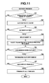
- FIG. 21 is a flowchart to help explain an overall operation control in the client apparatus 20 of the thin client system.
- FIG. 1 is a block diagram showing the configuration of a thin client system which includes a server apparatus 10 and its client terminals 20 a , 20 b , . . . according to an embodiment of the invention.
- the thin client system includes a server apparatus 10 and a plurality of client apparatuses 20 a , 20 b , . . . which are connected to a network N composed of a local area network (LAN) or a wide area network (WAN).
- LAN local area network
- WAN wide area network
- the server apparatus 10 has a plurality of application programs, including a document creating program, a spreadsheet program, a mail handling program, an Internet connection program, and a Web display program, and is activated according to the operation input signal from the client apparatuses 20 a , 20 b , . . . connected to the server apparatus 10 and executes the process.
- application programs including a document creating program, a spreadsheet program, a mail handling program, an Internet connection program, and a Web display program
- drawing data for display output created as a result of the execution of an application program corresponding to the operation input signals from the client apparatuses 20 a , 20 b , . . . is not only converted into transfer drawing data by accelerator circuits 101 a , 101 b , . . . but also compressed by the optimum compression method according to the contents of the drawing data and the state of communication with the client apparatuses 20 a , 20 b , . . . and transmitted (transferred) to the accessing client apparatuses 20 a , 20 b, . . . .
- the drawing data transferred from the server apparatus 10 is decoded at the accelerator circuits (circuit boards) 21 a , 21 b , . . . of the respective client apparatuses and is displayed on the respective display sections.
- each of the client apparatuses 20 a , 20 b , . . . of the thin client system has only an input function corresponding to the user operation on a keyboard or a mouse and an output function, such as an LCD section or a printer, and has neither its own application function nor data file management function.
- the data file created by various processes executed at the server apparatus 10 according to the operation input signals from the client apparatuses 20 a , 20 b , . . . is stored by user account or as a common file in the server apparatus 10 or a storage unit, such as a magnetic disk, managed by the server apparatus 10 .
- FIG. 2 shows a state where drawing data created at the server apparatus 10 of the thin client system is transferred to the client apparatus 20 .
- A shows a change in the drawing data at the server apparatus 10 .
- B shows transfer drawing data when the drawing data has changed.
- C shows the display output state of the transferred drawing data at the client apparatus.
- the transfer drawing data H is created by comparing the area Q′ clipped according to the changed part P from the changed drawing data G′ with the same area Q in the unchanged drawing data G and converting the background coinciding area R into transmittable drawing data (image data) S (color data requiring no rewriting).
- image data color data requiring no rewriting
- the transfer drawing data H is written in the coordinate position corresponding to the image changed area Q′ on the unchanged drawing data G, with the transmittable image data S removed, which enables the drawing data G′ after the change to be displayed.
- the transfer drawing data H created at the accelerator circuit 101 of the server apparatus 10 is compressed and transferred by the optimum compression method in terms of both compression coefficient and image quality selected according to the contents (the number of colors) of the drawing data and the state (response speed) of communication with the client apparatus 20 at that time, the amount of drawing data to be transferred can be reduced further without degrading the drawing quality.
- FIG. 3 shows in detail transfer drawing data H created by the accelerator circuit 101 on the basis of the area Q′ of the changed drawing data G′ at the server apparatus 10 of the thin client system.
- the areas of tiles T in a horizontal line are collectively called one block.
- the area Q′ is a rectangular area Q′ obtained by clipping the image-changed part P in the horizontal and vertical directions
- the area size (lateral) clipped only in the horizontal direction may be a strip-shaped area Q′, or the area size (640 pixels) of the drawing data G (G′) itself.
- the accelerator circuit 101 compares, in tiles, the image in the area Q′ according to the image change with the image in the area Q in the same position of the unchanged drawing data G and converts the individual pixels in the background coinciding area R into transmittable image data S (color data requiring no rewriting) as shown by (B) in FIG. 3 .
- a transmittable color tile so obtained by converting the entire area of one tile (T) into transmittable color data S is not transferred.
- transfer drawing data H obtained by compressing the area of difference from the unchanged drawing data G
- the transfer drawing data H is compressed by the optimum compression method and the resulting data together with the coordinate position of the tile on the display screen is transferred to the client apparatus 20 .
- the accelerator circuit (circuit board) 21 of the client apparatus 20 decodes the transfer drawing data H obtained by compressing the unchanged drawing data G in tiles and then simply writes the decoded data in the coordinate position of the tile, with the image pixels converted into transmittable data S removed, thereby making it possible to display the changed drawing data G′ created at the server apparatus 10 .
- the accelerator circuit 101 of the server apparatus 10 compresses and encrypts the created transfer drawing data H optimally and transfers the resulting data to the client apparatus 20 .
- the compression efficiency can be increased without degrading its picture quality. Accordingly, as described above, the compression ratio of the drawing data area converted into transmittable color data S in the transfer drawing data H is very high.
- the processing burden on the server apparatus 10 can be alleviated remarkably and the increase of client apparatuses 20 a , 20 b , . . . or the like can be dealt with easily.
- FIG. 4 is a block diagram showing the circuit configuration of the server apparatus 10 in the thin client system.
- the server apparatus 10 includes a CPU 102 serving as a computer.
- a ROM 104 , a RAM 105 , and a display unit 106 are connected via a high-speed bus 103 to the CPU 102 .
- the accelerator circuit (circuit board) 101 is further connected to the CPU 102 .
- the accelerator circuit 101 is provided with a VRAM 107 .
- an input section 109 such as a keyboard, an external storage HDD (Hard Disk Drive) 110 , and a control section 111 for transmission and reception to and from the client apparatus 20 .
- HDD Hard Disk Drive
- the CPU 102 controls the operation of various parts of the circuitry using the RAM 105 as a working memory according to the system program and various application programs previously stored in the ROM 104 .
- the various programs are started and executed according to the key input signal from the input section 109 or the processing command signals and the like corresponding to the user operation received via the transmission/reception control section 111 from the client apparatus 20 .
- various items of data created by the application program started and executed according to the user command signal from the client apparatus 20 are caused to correspond to, for example, the user ID and are stored in the external storage HDD 110 .
- display drawing data is converted into transfer drawing data H at the accelerator circuit (circuit board) 101 using the VRAM 107 (see FIGS. 2 and 3 ).
- the transfer drawing data is compressed and encrypted optimally, the resulting data is transferred from the transmission/reception control section 111 to the client apparatus 20 .
- FIG. 5 is a block diagram showing the circuit configuration of the accelerator circuit 101 in the server apparatus 10 of the thin client system.
- the accelerator circuit 101 includes an interface circuit (I/F circuit) 11 a connected to the high-speed bus 103 from the server CPU 102 .
- I/F circuit interface circuit
- the VRAM 107 is connected via a memory controller 11 b.
- VRAM 107 display drawing data created by each application program started and executed at the CPU 102 according to the operation command signals from the individual client apparatuses 20 a , 20 b , . . . are allocated and stored as display A, display B, . . . for the respective client apparatuses 20 a , 20 b , Further in the VRAM 107 , transfer drawing data H converted and created at the accelerator circuit 101 on the basis of the individual drawing data items A, B, . . . are compressed and encrypted optimally and the resulting data items are stored as result A, result B.
- an image scaler 11 c which are for creating transfer drawing data H (result A, result B, . . . ) from the created display drawing data (display A, display B, . . . ) are connected.
- the individual circuits 11 c to 11 g for creating the transfer drawing data H operate according to a command code set in a command setting register 11 h via the interface circuit 11 a by the CPU 102 .
- the image scaler 11 c is for reducing the drawing data created by an application program corresponding to the operation command signal for each of the client apparatuses 20 a , 20 b , . . . to the display screen size for each of the client apparatuses 20 a , 20 b . . . .
- the drawing data whose size has been adjusted by the image scaler 11 c are stored as display A, display B, . . . in the VRAM 107 via the memory controller 11 b.
- the tile division circuit 11 d is for setting tile division number (length ⁇ width pixels per tile) according to the area size and tile-dividing the display drawing data (display A, display B, . . . ) read from the VRAM 107 .
- the image size of the drawing data (display A) for, for example, the client apparatus 20 a read from the VRAM 107 is 480 ⁇ 640 pixels as shown in FIGS. 2 and 3 , 16 ⁇ 16 pixels per tile (T) and a tile division is performed.
- the area setting size per tile (T) in the tile division may be set to the image size of drawing data, such as 8 ⁇ 8 pixels or 32 ⁇ 32 pixels.
- the image comparing circuit 11 e is for comparing the changed drawing data G′ (see FIG. 2 ) read from the VRAM 107 with the unchanged drawing data G (see FIG. 2 ) read from the VRAM 107 in units of one tile (T) divided by the tile dividing circuit 11 d and converting the image pixels with no change (difference) into transmittable color data S (see FIG. 3 ).
- the compression circuit 11 f compresses the data optimally and the encryption circuit 11 g encrypts the compressed data.
- the encrypted data is stored as a unit image of transfer drawing data H in the VRAM 107 .
- the CPU 102 reads the transfer drawing data and transfers it to the client apparatus 20 a.
- an image tile obtained by converting all of the image pixels in one tile (T) into transmittable color data S is not transferred to the client apparatus 20 a.
- the image comparing circuit lie, compression circuit 11 f , and encryption circuit 11 g convert the unchanged pixels of the changed drawing data (present drawing data) G′ into transmittable color data and compress and encrypt the data optimally only in a block area including the image-changed part P (see FIG. 2 ).
- FIG. 6 is a block diagram showing the configuration of the image comparing circuit 11 e in the accelerator circuit 101 of the server apparatus 10 .
- the preceding (unchanged) drawing data G created by the application started according to the operation command signal from the client apparatus 20 and the present (changed) drawing data G′ are stored. Further in the VRAM 107 , difference-compressed drawing data h (transfer drawing data H) created according to the difference between the present drawing data G′ and the preceding drawing data G and compressed and encrypted optimally is stored.
- the begin one block of data (in this case, 640 long ⁇ 16 wide in pixels: 40 tiles) in the present drawing data G′ is set in a present drawing data comparison 640 ⁇ 16 pixel register e 14 is set via a DMA circuit e 13 .
- the CPU 102 sets the start address of and the number of bytes in the preceding drawing data stored in the VRAM 107 in a preceding drawing start address register e 15 and a preceding drawing byte number register e 16 , respectively, the beginning one block of data (40 tiles) in the preceding drawing data G is set in a preceding drawing data comparison 640 ⁇ 16 pixel register e 17 is set via the DMA circuit e 13 .
- One block of data (40 tiles) of the present drawing data G′ set in the present drawing data comparison 640 ⁇ 16 pixel register e 14 is read in tiles (16 ⁇ 16 pixels) with 40 tiles in parallel with one another are read into the color sensing circuit e 18 (see FIG. 7 ). While transmittable color data S is specified by the number of colors used in each tile and the sensing of unused colors, 40 tiles are read in parallel with one another in the same tiles into the tile comparing circuit e 19 (see FIG. 8 ).
- the tile comparing circuit e 19 compares one block of the present drawing data G′ read from the present drawing data comparison 640 ⁇ 16 pixel register e 14 with one block of the preceding drawing data G read from the preceding drawing data comparison 640 ⁇ 16 pixel register e 17 according to a comparison command signal from the CPU 102 in such a manner that drawing color data items are compared pixel by pixel in units of 40 tiles arranged in parallel. Then, the tile comparing circuit e 19 replaces the drawing color data on the pixels with no change (difference) in the image of the present drawing one-tile data with transmittable color data S of the corresponding one-tile data specified by the color sensing circuit e 18 .
- One block of data for 40 tiles obtained by replacing the drawing color data on the pixels with no change (difference) in the image with transmittable color data S on a tile basis at the tile comparing circuit e 19 is stored in a comparison result storage 640 ⁇ 16 pixel register e 20 .
- One block of data after the conversion of unchanged pixels into transmittable colors stored in the comparison result storage 640 ⁇ 16 pixel register e 20 is compressed and encrypted optimally in units of one block of data by the compression circuit 11 f and encryption circuit 11 g , respectively.
- the resulting data is stored as difference-compressed drawing data h into the VRAM 107 .
- a rewrite area decision circuit e 21 the number of block areas including the image-changed part P (see FIG. 2 ) in the present drawing data G′ stored in the VRAM 107 is set by the CPU 102 .
- the rewrite area decision circuit e 21 determines whether the input block data coincides with the set number of block areas each time the encryption circuit 11 g outputs a one-block end signal. If the input block data does not coincide with the set number of block areas, the rewrite area decision circuit e 21 outputs a signal for the comparison of the next block data to a +16 line circuit e 22 .
- the rewrite area decision circuit e 21 outputs to the CPU 102 an area block end signal which notifies the end of the creation of difference-compressed drawing data h in the present (changed) drawing data G′.
- the +16 line circuit e 22 updates the start address of the present drawing data G′ set in the present drawing start address register ell according to a comparison command signal for the next block data from the rewrite area decision circuit e 21 by adding 16 lines corresponding to one tile to the start address in the Y (longitudinal) direction.
- the +16 line circuit e 22 has added 16 lines, the number of lines may be set suitably according to the processing unit of drawing data. For example, when processing is done in units of, for example, 32 lines or 64 lines, 32 lines or 64 lines are added, respectively.
- the storage capacity of the present drawing data comparison 640 ⁇ 16 pixel register e 14 and the preceding drawing data comparison 640 ⁇ 16 pixel register e 17 and other circuits are set according to the processing unit of drawing data.
- a drawing data replacing register e 23 replaces the present drawing data G′ in the VRAM 107 with the preceding drawing data G via the DMA circuit e 13 when the CPU 102 has created and set new present (changed) drawing data G′, and writes the new present (changed) drawing data as present drawing data G′ over the old one.
- FIG. 7 is a block diagram showing the configuration of the color sensing circuit e 18 of the image comparing circuit 11 e in the accelerator circuit 101 of the server apparatus 10 .
- the color sensing circuit e 18 arranges one block of data (40 tiles) to be read into the tile comparing circuit e 19 in the present drawing data G′ stored in the present drawing data comparison 640 ⁇ 16 pixel register e 14 in such a manner that one block of data is arranged tile by tile in parallel with one another and stores the resulting data into a storage 16 ⁇ 16 pixel register 18 a.
- the color sensing circuit e 18 is composed of as many units of the processing circuit arranged in parallel as correspond to 40 tiles.
- One tile of data stored in the storage 16 ⁇ 16 pixel register 18 a is read by a one-pixel read circuit 18 b pixel by pixel and is not only sent to a one-pixel coincidence circuit 18 c but also set in a color register write circuit 18 d.
- the one-pixel coincidence circuit 18 c detects the agreement/disagreement of color data on one pixel read by the one-pixel read circuit 18 b with color data on the preceding read pixel in the present one-tile data read from a color register 18 f by a color register read circuit 18 e.
- a next color register read circuit 18 g updates the read position of the color register 18 f by the color register read circuit 18 e . If the one-pixel coincide circuit 18 c detects the agreement, a next pixel read circuit 18 h updates the read pixel in the storage 16 ⁇ 16 pixel register 18 a by the one-pixel read circuit 18 b.
- the color data on the disagreement-sensed pixel set in the color register write circuit 18 d is additionally stored in the color register 18 f and the color number count of the one-tile data in the color-number count register 18 i is updated.
- drawing color data on one pixel read sequentially by the one-pixel read circuit 18 b differs from and disagrees with drawing color data on the preceding pixel
- the different color data is additionally stored in the color register 18 f .
- the color number count in the color-number count register 18 i is updated.
- an END circuit 18 j detects the completion of the reading of 256 pixels corresponding to one tile of data and outputs a one-tile end signal.
- a sort circuit 18 k sorts the individual drawing color data items used in this tile stored in the color register 18 f in ascending order of color code.
- a discontinuous data sensing circuit 18 m is for detecting the first color code at which the continuation of the color codes ends and the color codes become discontinuous, in the process of sorting the drawing color codes (color codes) in ascending order at the sort circuit 18 k .
- the first color data in the color codes and unused in the detected tile is determined to be transmittable color data S in the one-tile data and is set in a transmittable color data specify register 19 d in the tile comparing circuit e 19 (see FIG. 8 ). Since unused color data in one tile is used as transmittable color data S, data indicating a transmittable color is unnecessary. However, if the code is not used in a bit train representing color codes, a specific code in the codes may be set uniquely as transmittable color data S.
- transmittable color data may be determined uniquely. In this case, the color sensing circuit e 18 is not needed. Furthermore, when transmittable color data is determined, the smallest color code used in the tile may be detected and used as transmittable color data S.
- FIG. 8 is a block diagram showing the configuration of the tile comparing circuit e 19 of the image comparing circuit 11 e in the accelerator circuit 101 of the server apparatus 10 .
- the tile comparing circuit e 19 of FIG. 8 is composed of as many one-tile processing circuits arranged in parallel as correspond to 40 tiles. As in the color sensing circuit e 18 , one block of data (40 tiles) read from the present drawing data comparison 640 ⁇ 16 pixel register e 14 is processed in parallel on a tile basis.
- a 16 ⁇ 16 pixel read circuit 19 a reads one tile (16 ⁇ 16 pixels) of data from each of one block of data in the present drawing data G′ stored in the present drawing data comparison 640 ⁇ 16 pixel register e 14 and one block of data in the preceding drawing data stored in the preceding drawing data comparison 640 ⁇ 16 pixel register e 17 .
- a 256-pixel parallel processing circuit 19 j processes drawing color data on the corresponding pixel in parallel for 256 pixels in one tile of data in each of the present drawing data G′ read from the 16 ⁇ 16 pixel read circuit 19 a and the preceding drawing data G.
- a one-pixel subtraction circuit 19 b of the 256 pixel parallel processing circuit 19 j subtracts drawing color data on the present drawing one pixel from drawing color data on the preceding pixel and outputs the result of the subtraction to a drawing color converting circuit 19 c.
- the drawing color converting circuit 19 c causes the present drawing color data to remain the drawing color data on the pixel.
- the drawing color converting circuit 19 c converts drawing color data on the pixel into transmittable color data S which is a drawing color not found in the tile and is set in a transmittable color data specify register 19 d by the color sensing circuit e 18 .
- One tile of data in the present drawing data G′ obtained by converting the pixels with no change in the drawing into transmittable data S by the 256-pixel parallel processing circuit 19 j is stored in a comparison result storage 16 ⁇ 16 pixel register 19 e .
- This data is stored in parallel with other 39 tiles of data obtained by processing 40 tiles of data in parallel into the comparison result storage 640 ⁇ 16 pixel register e 20 in the form of one-block data.
- the end sensing circuit 19 f When detecting the completion of the one-block (one-tile) process, the end sensing circuit 19 f outputs the one-tile end signal to a +1 count circuit 19 g , thereby updating the reading of the next present drawing block (tile) data from the present drawing 640 ⁇ 16 pixel register e 14 by the 16 ⁇ 16 pixel read circuit 19 a and the reading of the next preceding drawing block (tile) data from the preceding drawing 640 ⁇ 16 pixel register e 17 .
- the end sensing circuit 19 f outputs the one-block end signal to a compression circuit f 12 , thereby starting an optimum compression operation of the one-block data stored in the comparison result storage 640 ⁇ 16 pixel register e 20 .
- a transmittable color sensing circuit 19 h detects whether all of the pixels (256 pixels) in the tile are tile data with no change in the drawing converted into transmittable color data S for each tile in one-block data obtained by the parallel processing of 40 tiles stored in the comparison result storage 640 ⁇ 16 pixel register e 20 . Then, the transmittable color sensing circuit 19 h writes the detected value for each tile in one block into a transfer acknowledge register 19 i in such a manner that a tile (transmittable tile) where the conversion of all the pixels (256 pixels) into transmittable color data S has been sensed is determined to be “0” and the other tiles (drawing tiles) are determined to be “1.”
- the transfer acknowledge register 19 i stores sequentially the detected value “0” or “1” for each tile in one block subjected to the comparing process at the tile comparing circuit e 19 and detected block by block at the transmittable color sensing circuit 19 h for the entire area of each block data including the image changed part P in the present drawing data G′.
- the transmittable tile value “0” or the drawing tile value “1” for each tile in the entire block area corresponding to the image change stored in the transfer acknowledge register 19 i is read into the CPU 102 when the difference-compressed drawing data h about the present drawing data G′ created by the compared block data (equivalent to 40 tiles) sequentially stored in the comparison result storage 640 ⁇ 16 pixel register e 20 is transferred to the client apparatus 20 .
- the tile data with a transmittable tile value of “0” where all the pixels (256 pixels) have been converted into transmittable color data S is not transferred. Only the difference compression tile data with a drawing tile value of “1” is transferred.
- FIG. 9 is a block diagram showing the configuration of the compression circuit 11 f in the accelerator circuit 101 of the server apparatus 10 .
- FIG. 10 is a compression method decision table f 11 T included into compression method decision circuit f 11 of the compression circuit 11 f.
- the compression circuit 11 f is for optimally compressing one tile by one tile one-block data compared at the image comparing circuit 11 e and sequentially stored in the comparison result storage 640 ⁇ 16 pixel register e 20 .
- the compression circuit 11 f includes a compression method decision circuit f 11 .
- the compression method decision circuit f 11 stores a compression method decision table f 11 T as shown in FIG. 10 . According to the color number count (X, Y, Z) of each of the 40 tiles in one-block drawing data detected by the color sensing circuit (see FIG.
- the compression method decision circuit f 11 determines optimally on any one of the PRE (Rise-and-Run-length Encoding) method, the GIF (Graphics Interchange Format)/PNG (Portable Network Graphics) encoding method, and the JPEG (Joint Photographic Coding Experts Group) encoding method as a method of compressing data one tile by one tile in one-block data sequentially stored in the comparison result storage 640 ⁇ 16 pixel register e 20 .
- An encode value signal for specifying the encoding method optimally determined by the compression method decision circuit f 11 is output to a compression select circuit f 14 .
- the RRE encoding method which has a high compression efficiency when adjacent pixels have a high same-color continuity is set as the compression method, regardless of the response time (A, B, C) of the client apparatus 20 .
- the GIF/PNG encoding method which has a high compression efficiency when adjacent pixels have a high same-color continuity giving priority to image quality is set as the compression method.
- Quality means the image quality of the result of the processing.
- Quality is low (close to 0), this means that the image quality is low and the compression ratio is high.
- Quality is high (close to 9), this means that the image quality is relatively high and the compression ratio is relatively low.
- the compression select circuit f 14 selectively distributes and outputs one-tile data to be compressed read from the comparison result storage 640 ⁇ 16 pixel register e 20 or present drawing data comparison 640 ⁇ 16 pixel register e 14 to an RRE encoder f 15 , a GIF/PNG encoder f 16 , or a JPEG encoder f 17 .
- the JPEG encoding method (Quality 9 to Quality 0 ) at the JPEG encoder f 17 is a lossy compression method, the decoded drawing data cannot be restored in pixels completely to its original state.
- the JPEG encoding method (Quality 9 to Quality 0 ) is determined on the basis of the compression method decision table f 11 T (see FIG. 10 ). Only in a case (Z) where the color number count of a tile to be compressed is very large, or 256 or more colors, as when the compression method decision circuit f 11 outputs encode values J 9 to J 0 , the compression select circuit f 14 selects the present drawing data comparison 640 ⁇ 16 pixel register e 14 and the corresponding tile data in the present drawing one-block data not converted (difference-compressed) into transmittable color data S by the tile comparing circuit e 19 is set to the JPEG encoder f 17 , which compresses the data optimally.
- the JPEG encoding method (Quality 9 to Quality 0 ) at the JPEG encoder f 17 is a lossless compression method, such as JPEG 2000
- the decoded drawing data can be restored in pixels completely to its original state.
- one-tile data to be compressed is read from one-block data in the comparison result storage 640 ⁇ 16 pixel register e 20 converted (difference-compressed) into transmittable color data S by the tile comparing circuit e 19 .
- the selecting operation for one-tile data by the compression select circuit f 14 is detected by an end sensing circuit f 18 .
- an end sensing circuit f 18 According to a one-tile end sense signal output from the end sensing circuit f 18 , not only does a tile read circuit f 19 output a next one-tile read command signal to the comparison result storage 640 ⁇ 16 pixel register e 20 , but a determined data read circuit f 20 also outputs a determined compression method read command signal for the next tile to be compressed to the compression method decision circuit f 11 .
- one-tile data compressed sequentially by the RRE encoder f 15 , GIF/PNG encoder f 16 , or JPEG encoder f 17 is output to a sequence encryption circuit 11 g , which encrypts the data and stores the resulting data as difference-compressed drawing data h in the VRAM 107 each time one block has been finished.
- the difference-compressed drawing data h in the VRAM 107 is created by writing transmittable color data S into the pixels with no change in the drawing on a tile basis for each block in the n block data clipped according to the image-changed part P from the preceding data G in the present drawing data G′ and then compressing and encrypting the resulting data optimally in terms of compression ratio and image quality.
- FIG. 11 is a flowchart to help explain an overall operation control in the server apparatus 10 of the thin client system.
- step S 1 When the server apparatus 20 has received a connection request signal from the client apparatuses 20 a , 20 b , . . . (step S 1 ), the client apparatuses 20 a , 20 b , . . . requesting the connection are authenticated on the basis of confirmation and collation, such as IDs or passwords (step S 2 ).
- step S 3 If it is determined that the authentication is acceptable (step S 3 ), the IDs for the client apparatuses 20 a , 20 b , . . . authenticated as acceptance are issued (step S 4 ).
- a transfer data thread process for each connected client apparatus (see FIG. 12 ) is started, thereby starting and executing applications corresponding to various requests from the client apparatuses 20 a , 20 b , . . . and creating and transmitting and receiving the resulting data (step SA).
- step S 5 When a disconnection request has been received from the client apparatus 20 in the connecting process (step S 5 ), the process of creating data and transmitting and receiving the data to and from the client apparatus 20 a requesting the disconnection is terminated (step S 6 ).
- step S 7 the process of creating data and transmitting and receiving the data to and from all the connected client apparatuses 20 a , 20 b , . . . is terminated (step S 8 ).
- FIG. 12 shows a transfer data thread process by client (step SA) accompanying a service process in the server apparatus 10 , (A) showing its flowchart and (B) showing a transfer data format in tiles.
- step A 1 when the applications according to various requests from the connected client apparatuses 20 a , 20 b , . . . are started and executed and the process of creating data and transmitting and receiving the data is carried out (step A 1 ), for example, as shown by (A) in FIG. 2 , if it has been determined that, for example, the present drawing data G′ has been updated with respect to the preceding drawing data G (step A 2 ), the starting point coordinates (X, Y) of the drawing area Q′ corresponding to the image changed part P resulting from the drawing update, the horizontal and vertical size (h, w), and its number of drawing colors are analyzed (step A 3 ). Then, it is determined whether the area size of the drawing area Q′ is larger than a preset area size Dt and/or the number of drawing colors is larger than a preset number of colors Dc (step A 4 ).
- the processing burden on the server apparatus 10 will be heavier.
- the accelerator circuit (circuit board) 101 explained in FIGS. 4 to 11 as a result of the control processes in step A 5 to step A 13 , the difference-compressed drawing data h corresponding to the drawing area Q′ is created and compressed and encrypted optimally and the data is transferred to the client apparatus 20 corresponding to the execute application (step A 4 ⁇ A 5 to A 13 ).
- the processing burden on the server apparatus 10 will be lighter.
- the software process mainly composed of a software difference process ( FIGS. 15 to 17 ) and a software optimum encoding process ( FIG. 18 ) explained later in step A 14 to step A 21 , the difference-compressed drawing data h corresponding to the drawing area Q′ is created and compressed and encrypted optimally and the data is transferred to the client apparatus 20 corresponding to the execute application (step A 4 A 14 to A 21 ).
- step A 4 if control is passed to the hardware process mainly carried out by the accelerator circuit (circuit board) 10 (step A 4 (YES)), it is determined whether the accelerator circuit 101 of the server apparatus 10 is idle and usable (step A 5 ). If it has been determined that the accelerator circuit 101 can be used, the accelerator circuit 101 is started up (step A 5 ⁇ AB).
- FIG. 13 is a flowchart to help explain an accelerator circuit activating process executed when the accelerator circuit 101 of the server apparatus 10 is started.
- step B 1 When the starting point coordinates (X, Y) of and the horizontal and vertical size (h, w) of the drawing area Q′ corresponding to the image changed part P of the present drawing data G′ created by the running application according to the operation command signal from the client apparatus 20 are obtained (step B 1 ), the communication response time of the client apparatus 20 corresponding to the running application is detected (step B 2 (see FIG. 14 )).
- FIG. 14 is a flowchart to help explain a response time sensing process accompanying the accelerator circuit activating process at the server apparatus 10 .
- the communication response time Nx of the client apparatus 20 is measured and stored temporarily (step B 24 ) and then is added to the total measured response time Ny up to the preceding measurement, thereby calculating a new total measured response time Ny (step B 25 ).
- the counter i is counted up (step B 28 ) at regular intervals of time, for example, at intervals of 800 ms, (step B 27 ) ten times, thereby calculating a total measured response time Ny (step B 24 to step B 26 ).
- the measuring time interval 800 ms of the response time (step B 27 ) has to be set longer than the response time decision condition 500 ms in the compression method decision table f 11 T (see FIG. 10 ).
- step B 24 When the total measured response time Ny for ten times has been calculated in the repetitive processing in step B 24 to step B 28 , the total measured response time Ny is divided by “10,” thereby calculating its average response time Nt (step B 26 ⁇ step B 29 ).
- step B 3 the start address of and the number of bytes in the drawing area Q′ corresponding to the image change in the present drawing data G′ stored in the VRAM 107 are set in the present drawing start address register ell and its present drawing byte number register e 12 in the image comparing circuit 11 e (see FIG. 6 ) of the accelerator circuit 101 , respectively (step B 3 ).
- step B 4 the start address of and the number of bytes in the preceding drawing data G corresponding to the image-changed drawing area Q′ are set in the preceding drawing start address register e 15 and its preceding drawing byte number register e 16 in the same image comparing circuit 11 e , respectively.
- a comparison start signal is output to the tile comparing circuit e 19 of the image comparing circuit 11 e in the accelerator circuit 101 (step B 5 ).
- the number of block areas corresponding to the image changed drawing area Q′ in the present drawing data G′ is set in the rewrite area decision circuit e 21 of the same image comparing circuit 11 e (step B 6 ).
- the response time information Nt measured in the process of detecting the communication response time of the client apparatus 20 in step B 2 is set in the client response time information circuit f 13 of the compression circuit (see FIG. 9 ) in the accelerator circuit 101 (step B 7 ).
- the image scaler process at the image scaler 11 c the tile division process at the tile dividing circuit 11 d , the image comparing process at the image comparing circuit 11 e , the optimum compression process at the compression circuit 11 f , and the encryption process at the encryption circuit 11 g are carried out in a hardware circuit as explained in FIGS. 5 to 10 .
- difference-compressed drawing data h is created for each block (40 tiles) of data corresponding to the image-changed drawing area Q′ in the present drawing data G′ and the resulting data is stored sequentially into the VRAM 107 (step AB).
- difference-compressed drawing data h is created for each of the block areas corresponding to the image-changed drawing area Q′ in the present drawing data G′.
- the rewrite area decision circuit e 21 outputs an area block end signal, thereby completing the series of processes (step B 8 ⁇ END).
- step AB In the hardware process (step AB) at the accelerator circuit 101 , when an interrupt signal indicating the end of one block is generated (step A 6 ), one-tile data in the one block of difference-compressed data h is read (step A 7 ) and, at the same time, the transmittable color detected value (transmittable tile value “0” or drawing tile value “1”) corresponding to the one tile stored in the transfer acknowledge register 19 i (see FIG. 8 ) is read. Then, it is determined whether the detected value is the drawing tile value “1” including a drawing-changed image pixel or the transmittable tile value “0” obtained by converting all the image pixels into transmittable color data S (step A 8 ).
- the one-tile data is created as transfer data to whose header the coordinates on the present drawing data G′, the transmittable color code, the compression method, and the forwarding client ID are added as shown by (B) in FIG. 12 (step A 9 ).
- the one-tile data is then transferred to the client apparatus 20 with the ID shown in the header (step A 10 ).
- step A 11 if it has been determined that all of the tiles (40 tiles) in one block of difference-compressed data h have not been transferred yet (step A 11 (NO)), the next one-tile data in the same block of data is specified (step A 12 ) and the next one-tile data in the one block of difference-compressed data h is read (step A 7 ).
- step A 8 if it has been determined that the transmittable tile value “0” indicating all the image pixels have been converted into transmittable color data S has been read from the transfer acknowledge register 19 i in the one-tile data read from one block of difference-compressed data h in step A 8 (step A 8 (NO)), the one-tile data is not transferred and the next one-tile data in the same block of data is specified (step A 12 ), thereby reading the next one-tile data in the one block of difference-compressed data h (step A 7 ).
- step A 8 to step A 12 the process of creating transfer data in the one-tile data and the process of transmitting the data to the client apparatus 20 when the drawing tile value “1” has been read from the transfer acknowledge register 19 i (step A 8 to step A 12 ), or the process of not transferring the one-tile data when the transmittable tile value “0” has been read from the transfer acknowledge register 19 i (step A 8 ⁇ step A 12 ) are carried out repeatedly.
- step A 11 YES
- step A 6 since the rewrite area decision circuit e 21 has generated no area block end signal, it is determined that the tile-unit transfer of all the blocks of difference-compressed drawing data h has not been completed (step A 13 (NO)), the accelerator circuit 101 is waited for to output one-block end signal (step A 6 ).
- step AB the accelerator circuit 101
- step A 6 the accelerator circuit 101
- the process of creating transfer data in the one-tile data and the process of transmitting the data to the client apparatus 20 when the drawing tile value “1” has been read from the transfer acknowledge register 19 i (steps A 7 , A 8 to step A 12 ), or the process of not transferring the one-tile data when the transmittable tile value “0” has been read from the transfer acknowledge register 19 i (steps A 7 , A 8 ⁇ step A 12 ) are carried out repeatedly for one-tile data sequentially read from the one block of difference-compressed data h.
- difference-compressed data h for each block (40 tiles) corresponding to the image-changed drawing area Q′ in the present drawing data G′ created by the accelerator circuit 101 is transferred or not transferred to the client (ID) unit 20 according to the drawing tile value “1” or the transmittable tile value “0” on a one-tile basis.
- step A 13 YES
- the hardware process at the accelerator circuit 101 makes it possible to create as transfer data at high speed the difference-compressed drawing data h obtained by writing transmittable color data S into the unchanged image pixels in tiles in the image-changed drawing area Q′ in the present drawing data G′ and compressing the resulting data optimally.
- the transmittable detected tile “0” obtained by converting all the image pixels in one tile into transmittable color data S is not transferred to the client apparatus 20 . Only the drawing detected tile “1” with a change in the image is transferred. Only a changed tile division part is extracted from the preceding drawing data G in the updated present drawing data G′ and is compressed optimally, thereby realizing a minimum amount of transfer data, while maintaining the image quality. Further, it is possible to transfer the drawing data created and updated by the application to the client apparatus at a high speed with a high quality.
- step A 4 if it has been determined that the area size of the image-changed drawing area Q′ in the present drawing data G′ is equal to or smaller than the preset area size Dt and/or the number of drawing colors is equal to or smaller than the preset number of colors Dc, control is passed to the software process mainly composed of a software difference process ( FIGS. 15 to 17 ) and a software optimum encoding process ( FIG. 18 ) explained later (step A 4 (NO)).
- the drawing area Q′ corresponding to the image change is read (step A 14 ) and tile division is performed in such a manner that a 16 ⁇ 16 pixel area or a 64 ⁇ 64 pixel area is assigned to one tile (step A 15 ).
- control is passed to a software difference process as shown in FIGS. 15 to 17 (step AE).
- FIG. 15 is a flowchart to help explain a software difference process (part 1 ) for each divided tile when control is passed to a software process as a result of the transfer data thread process by client at the server apparatus 10 .
- FIG. 16 is a flowchart to help explain a software difference process (part 2 ) for each divided tile when control is passed to the software process as a result of the transfer data thread process by client at the server apparatus 10 .
- FIG. 17 is a flowchart to help explain a number-of-colors counting and transmittable color setting process for each divided tile accompanying a software difference process in the software process at the server apparatus 10 .
- control is passed to the number-of-colors counting and transmittable color setting process in FIG. 17 , thereby setting a transmittable color by the count of the color number for a first tile data item divided in the drawing area Q′.
- step F 1 When the number-of-colors counting and transmittable color setting process is started, counter i, a drawing color data storage array X [255], a drawing color data storage variable Y, a drawing color setting variable Z, a color data holding array C [255], and a color number counter variable CC are set in the RAM 105 (step F 1 ).
- step F 9 NO
- color data item (code) next to (+1) the color data item (code) C[i] is set as transmittable color Z of the tile (step F 13 ).
- step F 15 a similar determining process is carried out repeatedly (step F 15 ⁇ F 14 , F 15 ). Then, if it has been determined that the color data item (code) j counted up does not coincide with each of the color data items (codes) C[i . . . ] sorted in ascending order, the counted-up color data item (code) j which does not coincide with the color data items (codes) C[i . . . ]sorted in ascending order for the first time is set as transmittable color Z for the tile (step F 16 ).
- step EF color data the tile does not have is set as its transmittable color Z in the number-of-colors counting and transmittable color setting process of FIG. 17. Then, the pixel coordinates (X0, Y0) of the starting point of the one-tile area and the pixel coordinates (X1, Y1) of its ending point are obtained (steps E 1 , E 2 ).
- step E 8 pixel data pd 0 obtained from the present drawing one-tile data is not the same as (or differs from) pixel data pd 1 in the same position obtained from the preceding one-tile data (step E 8 (NO))
- pixel data pd 0 after the change is written in the pixel position indicated by the moving counter (Xt, Yt) in the one-tile data transfer image area (step E 10 ).
- step E 6 the process of acquiring present drawing pixel data pd 0 in a position to which the pixel specify position is moved one pixel horizontally and the preceding pixel data pd 1 (steps E 6 , E 7 ) and the process of writing pixel data pd 0 after the change or transmittable color data pd 2 into a transfer image area according to the presence or absence of a change in the image (steps E 8 to E 10 ) are repeated.
- step E 4 control is returned to the processes in step E 4 and forward.
- step E 6 the process of acquiring present drawing pixel data pd 0 from the horizontal starting point position to which the pixel specify position has been moved one pixel vertically and the preceding pixel data pd 1 (steps E 6 , E 7 ) and the process of writing pixel data pd 0 after the change or transmittable color data pd 2 into a transfer image area according to the presence or absence of a change in the image (steps E 8 to E 10 ) are repeated.
- step E 6 , E 7 the process of acquiring present drawing pixel data pd 0 in each pixel specify position on one-tile data and the preceding pixel data pd 1 (steps E 6 , E 7 ) and the process of writing pixel data pd 0 after the change or transmittable color data pd 2 into a transfer image area according to the presence or absence of a change in the image (steps E 8 to E 10 ) are repeated (steps E 4 to E 13 ).
- step E 12 determines whether the vertical moving counter Yt counted up has exceeded the ending point coordinate Y1 (Yt>Y1) (step E 4 (NO)) and one-tile data transfer image area where changed pixel data is used as pixel data pd 0 as it is and unchanged pixel data is converted into transmittable color data pd 2 has been formed from the present drawing on-tile data
- step AJ the software difference process of the tile is completed and control proceeds to a software optimum encoding process of FIG. 18.
- FIG. 18 is a flowchart to help explain a software optimum encoding process for each divided tile when control is passed to a software process as a result of the transfer data thread process by client at the server apparatus 10 .
- step AE color number data on the one-tile data transfer image area formed by using the changed pixel data as pixel data pd 0 as it is and converting the unchanged pixel data into transmittable color data pd 2 is read in the software difference process (step AE) in FIGS. 15 and 16 (step J 1 ). Then, it is determined whether all the pixel data items in the one-tile data transfer image area are one-tile data with a change, not transmittable color data pd 2 , or whether all the pixel data items are one-tile data with no change or transmittable color data pd 2 (step J 2 ).
- step J 2 If it has been determined that all the pixel data items in the one-tile data transfer image area are one-tile data with a change, not transmittable color data pd 2 (step J 2 (YES)), it is determined whether the number of colors in the one-tile data is smaller than 256 colors (or equal to or larger than 256 colors) (step J 3 ). If it has been determined that the number of colors is smaller than 256 colors (step J 3 (YES)), it is further determined whether the number of colors is three colors or more (or 2 colors or less) (step J 4 ).
- step J 4 If it has been determined in step J 4 that the number of colors in the one-tile data is two colors or less (step J 4 (NO)), a compression process is carried out by an RRE circuit whose compression method has a high compression ratio when the continuity of the same colors in adjacent pixels is high (step J 11 ).
- step J 4 a compression process is carried out by a GIF circuit or a PNG circuit whose compression method has a high compression ratio when the continuity of the same colors in adjacent pixels, giving priority to image quality, is high (step J 6 ).
- step J 3 If it has been determined in step J 3 that the number of colors in the one-tile data is as large as 256 colors or more (step J 3 (NO)), a compression process is carried out by a JPEG circuit (JPEG 2000) with a low compression (high quality) in a communication state where a high-speed transfer with the response time with the client apparatus 20 being less than 500 ms is possible (step J 9 ).
- JPEG 2000 JPEG 2000
- step J 3 if it has been determined in step J 3 that the number of colors in the one-tile data is as large as 256 colors or more (step J 3 (NO)), if a low-speed transfer is carried out with the response time with the client apparatus 20 being 500 ms more (steps J 7 , J 8 (NO)), a compression process is carried out by a JPEG circuit (JPEG 2000) with a high compression (low quality) (step J 10 ).
- the selection of the compression method is supposed to include the selection of compression ratios in the same compression method. For example, when the number of colors is large in the same JPEG compression, the compression ratio is made high. When the number of colors is small in the same JPEG compression, the compression ratio is made low. This makes it possible to keep the transfer data flowing through the network constant and use the network channels efficiently, which produces the effect of suppressing the deterioration of the display quality of the client apparatus.
- the one-tile data is not only stored as transfer data (step J 11 ) but also encrypted (step J 12 ).
- the optimally compressed and encrypted transfer one-tile data (see (B) in FIG. 12 ) is created as one-tile transfer data to whose header the coordinates on the present drawing data G′, the transmittable color code, the compression method, and the forwarding client ID are added (step A 18 ).
- the resulting one-tile transfer data is transferred to the client apparatus 20 with the ID shown in the header.
- step A 21 the next divided one-tile data item in the drawing area Q′ is read (step A 21 ) and a one-tile data transfer image area is created and compressed and encrypted optimally in the software difference process and optimum encoding process in steps AE, AJ as described above.
- step J 2 in the software optimum encoding process if it has been determined that all the pixel data items in the one-tile data transfer image area are transmittable color data pd 2 and one-tile data with no change (step J 2 (NO)), the one-tile data item is not transferred and the next divided one-tile data item in the drawing area Q′ is read (step A 21 ) and a one-tile data transfer image area is created and compressed and encrypted optimally in the software difference process and optimum encoding process in steps AE, AJ as described above.
- the process of creating transfer data obtained by compressing and encrypting the one-tile data when it has been determined that all the pixel data items are one-tile data with a change, not transmittable color data pd 2 and the process of transmitting the transfer data to the client apparatus 20 are carried out repeatedly.
- the process of not transferring the one-tile data when all the pixel data items are transmittable color data pd 2 and one-tile data with no change is carried out repeatedly.
- step A 20 if it has been determined that the tile-unit transfer of all the divided tile data items has been completed (step A 20 (YES)), control returns to step A 2 , where the update of the next drawing data resulting from the execution of the application is waited for to be determined.
- the software process makes it possible to create transfer data obtained by writing transmittable color data Z(pd 2 ) into the unchanged image pixels tile by tile in the image-changed drawing area Q′ in the present drawing data G′ and compressing the resulting data optimally.
- the transfer data obtained by converting all the image pixels in one tile into transmittable color data Z(pd 2 ) is not transferred to the client apparatus 20 . Only the transfer data with a change in the data is transferred to the client apparatus 20 . Consequently, only the changed tile divided parts are extracted from the preceding drawing data G in the updated present drawing data G′ and are compressed optimally, which minimizes the amount of transfer data while maintaining the image quality. This makes it possible to transmit the drawing data created and updated by the application to the client apparatus at a high speed with a high quality.
- FIG. 19 is a block diagram showing a circuit configuration of the client apparatus 20 in the thin client system.
- the client apparatus 20 includes a CPU 22 serving as a computer. Not only a ROM 24 and a RAM 25 but also the accelerator circuit 21 is connected via a bus 23 to the CPU 22 .
- the accelerator circuit 21 is provided with a VRAM 26 . Drawing data written in the VRAM 26 is output to a display unit 27 , which displays the drawing data.
- an input section 28 such as a keyboard, an external storage HDD (Hard Disk Drive) 29 , a USB/parallel/serial interface 31 for connecting various external units 30 , including an authentication device, a bar-code reader, a CCD camera, a printer, and a wireless device, a transmission/reception control section (wired/wireless) 32 for transmitting and receiving data to and from the server apparatus 10 .
- an input section 28 such as a keyboard, an external storage HDD (Hard Disk Drive) 29 , a USB/parallel/serial interface 31 for connecting various external units 30 , including an authentication device, a bar-code reader, a CCD camera, a printer, and a wireless device, a transmission/reception control section (wired/wireless) 32 for transmitting and receiving data to and from the server apparatus 10 .
- an input section 28 such as a keyboard, an external storage HDD (Hard Disk Drive) 29 , a USB/parallel/serial interface 31 for connecting
- the CPU 22 controls the operation of various parts of the circuitry using the RAM 25 as a working memory according to a system program previously stored in the ROM 24 .
- the system program is started and executed according to the key input signal from the input section 28 or the application response signal and transfer drawing data received via the transmission/reception control section 32 from the server apparatus 10 .
- various data items created by executing the application program in the server apparatus 10 are read and stored into the external storage HDD 29 .
- the created and transferred display drawing data is decoded at the accelerator circuit 21 .
- the decoded data is written into the VRAM 26 and displayed on the display unit 27 .
- FIG. 20 is a block diagram showing a circuit configuration of the accelerator circuit 21 in the client apparatus 20 of the thin client system.
- a one-tile of transfer drawing data (see (B) in FIG. 12 ) corresponding to the drawing area Q′ in the present drawing data G′ created, compressed optimally, and encrypted by the hardware process carried out by the accelerator circuit 101 of the server apparatus 10 or by the software process and transferred sequentially in units of one-tile data is stored in a header data/16 ⁇ 16 compressed-image data register 211 .
- the coordinates of the display position of the one-tile data read from the header data of the tile of transfer drawing data stored in the header data/16 ⁇ 16 compressed-image data register 211 are set in a display coordinate register 212 .
- the transmittable color data S (Z) in the one-tile data and the compression method are set in a transmittable color and compression method decision register 213 .
- the transmittable color data S(Z) is also set in a transmittable color register 214 .
- the tile of transfer drawing data stored in the header data/16 ⁇ 16 compressed-image data register 211 is decoded at a 16 ⁇ 16 compressed-image data decoder 215 according to the compression method for the one-tile data set in the transmittable color and compression method decision register 213 .
- the resulting data is stored in a 16 ⁇ 16 decompressed-image data register 216 .
- the decompressed one-tile drawing data stored in the 16 ⁇ 16 decompressed-image data register 216 is read pixel data item by pixel data item by a one-pixel read circuit 217 .
- a one-pixel decision circuit 218 determines whether the one-pixel data item is transmittable color data S(Z) for the one-tile data item set in the transmittable color register 214 .
- the one-pixel read circuit 217 updates the pixel read position according to a command signal from a next pixel command circuit 219 and reads the next one-pixel data item.
- a memory controller 220 writes image data on the pixel read this time into the VRAM 26 according to the coordinates representing the display position of the one-tile data set in the display coordinate register 212 .
- the one-pixel read circuit 217 updates the pixel read position according to the command signal output from the next pixel command circuit 219 , thereby reading the next one-pixel data item.
- FIG. 21 is a flowchart to help explain an overall operation control in the client apparatus 20 of the thin client system.
- step K 1 an initial screen set by default together with various initial setting processes is displayed on the display unit 27 (step K 2 ), going into an event waiting state (step K 3 ).
- step K 5 when the CPU 22 has received the key code as a result of the operation of the keyboard on the input section 28 (step K 5 ⁇ step K 6 ), the received key code is protocol-converted (step K 12 ) and subjected to a packet communication process (step K 13 ). The resulting signal is transmitted to the server apparatus 10 according to a transfer command (step K 14 ).
- step K 9 when the mouse cursor has been moved on the display screen as a result of the operation of the mouse at the input section 28 (step K 7 ⁇ step K 8 ) and the data extracted according to the operation of the mouse is received by the CPU 22 (step K 9 ), the received extracted data is protocol-converted (step K 12 ) and subjected to a packet communication process (step K 13 ). The resulting data is transmitted to the server apparatus 10 according to a transfer command (step K 14 ).
- step K 10 when data from various external units connected via the USB/parallel/serial interface 31 are received by the CPU 22 (step K 10 ⁇ step K 11 ), the received data is protocol-converted (step K 12 ) and subjected to a packet communication process (step K 13 ). The resulting data is transmitted to the server apparatus 10 according to a transfer command (step K 14 ).
- step K 4 when one tile of transfer drawing data transmitted from the server apparatus 10 is received via the network N (LAN) (step K 4 ), the TCP-IP protocol header is analyzed and extracted (step K 15 ), the coordinates indicating the display position of the one-tile data are transferred and set in a display coordinate register 212 (step K 16 ), and the one tile of drawing data is transferred to the accelerator circuit 21 (see FIG. 20 ) (step K 17 ).
- step K 18 when the accelerator circuit 21 has output a one-tile end signal (step K 18 ), a display command is output (step K 19 ), causing the display screen data to be updated on the basis of the one-tile of transfer drawing data written in the VRAM 26 of the accelerator circuit 21 .
- the client apparatus 20 it is determined whether the drawing data optimally compressed, encrypted, and transferred tile data item by tile data item from the server apparatus 10 is transmittable color data S(Z) set in the one-tile data decoded one-pixel data item by one-pixel data item by the accelerator circuit 21 .
- the display of pixel data with no image change, transmittable color data (S), is not updated. Only the display of pixel data with an image change, not transmittable color data S(Z), is updated. Consequently, it is possible to display and update the drawing data transferred and received from the server apparatus 10 at high speed without imposing a heavy burden on the CPU 22 even at the client apparatus 20 .
- the software optimum encoding process for each divided tile when control is passed to the software process as a result of the transfer data thread process by client shown in the flowchart of FIG. 18 can be stored as a computer-executable program into an external recording medium, such as a memory card (e.g., a ROM card or a RAM card), a magnetic disk (e.g., a floppy disk or a hard disk), an optical disk (e.g., a CD-ROM or a DVD), or a semiconductor memory, and be distributed.
- a memory card e.g., a ROM card or a RAM card
- a magnetic disk e.g., a floppy disk or a hard disk
- an optical disk e.g., a CD-ROM or a DVD
- semiconductor memory e.g., a semiconductor memory
- the computer (CPU 102 ) of the server apparatus 10 reads the program stored in the external recording medium into a storage unit ( 110 ) and controls the operation according to the read-in program, thereby realizing the process of creating transfer drawing data (difference-compressed drawing data h) when the drawing is updated, the optimum compression process, and the process of transferring the resulting data to the client apparatus 20 explained in the embodiment, which enables similar processes to be carried out by the above-described methods.
- data on the programs to realize the various methods can be transferred over a communication network (LAN) N in the form of program codes.
- the program data may be taken in via the transmission/reception control section 111 from the computer unit (program server) connected to the communication network (LAN) N and stored in the storage unit 110 , which makes it possible to realize the process of creating transfer drawing data (difference-compressed drawing data h) when the drawing is updated, the process of compressing the data optimally, and the process of transferring the resulting data to the client apparatus 20 .
Landscapes
- Engineering & Computer Science (AREA)
- Multimedia (AREA)
- Signal Processing (AREA)
- Computer Networks & Wireless Communication (AREA)
- General Engineering & Computer Science (AREA)
- Information Transfer Between Computers (AREA)
- Computer And Data Communications (AREA)
Applications Claiming Priority (4)
| Application Number | Priority Date | Filing Date | Title |
|---|---|---|---|
| JP2006-036652 | 2006-02-14 | ||
| JP2006036653A JP2007219626A (ja) | 2006-02-14 | 2006-02-14 | コンピュータシステムのサーバ装置、サーバ制御プログラム、およびそのクライアント装置 |
| JP2006-036653 | 2006-02-14 | ||
| JP2006036652A JP5046527B2 (ja) | 2006-02-14 | 2006-02-14 | コンピュータシステムのサーバ装置及びサーバ制御プログラム |
Publications (2)
| Publication Number | Publication Date |
|---|---|
| US20070192509A1 US20070192509A1 (en) | 2007-08-16 |
| US8918450B2 true US8918450B2 (en) | 2014-12-23 |
Family
ID=38370089
Family Applications (1)
| Application Number | Title | Priority Date | Filing Date |
|---|---|---|---|
| US11/674,514 Expired - Fee Related US8918450B2 (en) | 2006-02-14 | 2007-02-13 | Server apparatuses, server control programs, and client apparatuses for a computer system in which created drawing data is transmitted to the client apparatuses |
Country Status (3)
| Country | Link |
|---|---|
| US (1) | US8918450B2 (de) |
| EP (1) | EP1985104A2 (de) |
| WO (1) | WO2007094482A2 (de) |
Cited By (3)
| Publication number | Priority date | Publication date | Assignee | Title |
|---|---|---|---|---|
| US20140104289A1 (en) * | 2012-10-11 | 2014-04-17 | Samsung Display Co., Ltd. | Compressor, driving device, display device, and compression method |
| US10713756B2 (en) | 2018-05-01 | 2020-07-14 | Nvidia Corporation | HW-assisted upscaling and multi-sampling using a high resolution depth buffer |
| US11012694B2 (en) | 2018-05-01 | 2021-05-18 | Nvidia Corporation | Dynamically shifting video rendering tasks between a server and a client |
Families Citing this family (21)
| Publication number | Priority date | Publication date | Assignee | Title |
|---|---|---|---|---|
| JP4848801B2 (ja) * | 2006-03-09 | 2011-12-28 | カシオ計算機株式会社 | 画面表示制御装置および画面表示制御処理プログラム |
| WO2007114456A1 (en) * | 2006-03-29 | 2007-10-11 | Casio Computer Co., Ltd. | Server apparatus of computer system |
| JP5131891B2 (ja) * | 2006-06-23 | 2013-01-30 | カシオ計算機株式会社 | サーバ装置、サーバ制御プログラム、サーバ・クライアント・システム |
| JP4957126B2 (ja) * | 2006-08-31 | 2012-06-20 | カシオ計算機株式会社 | クライアント装置およびプログラム |
| JP4725587B2 (ja) * | 2008-03-18 | 2011-07-13 | カシオ計算機株式会社 | サーバ装置及びサーバ制御プログラム |
| JP4697321B2 (ja) * | 2009-03-24 | 2011-06-08 | カシオ計算機株式会社 | コンピュータシステム、クライアント装置及びプログラム |
| TW201037626A (en) * | 2009-04-01 | 2010-10-16 | Novatek Microelectronics Corp | Method for accessing image data and related apparatus |
| JP5241030B2 (ja) | 2009-09-01 | 2013-07-17 | 富士フイルム株式会社 | 画像送信装置、方法およびプログラム、画像出力装置ならびに画像送信システム |
| GB2481612A (en) * | 2010-06-30 | 2012-01-04 | Skype Ltd | Updating image regions in a shared image system |
| CN102903094B (zh) * | 2011-07-25 | 2015-09-02 | 株式会社理光 | 电子文档栅格化方法和电子文档栅格化装置 |
| US10095663B2 (en) | 2012-11-14 | 2018-10-09 | Amazon Technologies, Inc. | Delivery and display of page previews during page retrieval events |
| JP6369043B2 (ja) | 2013-03-15 | 2018-08-08 | 株式会社リコー | 配信制御システム、配信システム、配信制御方法、及びプログラム |
| JP2014200076A (ja) | 2013-03-15 | 2014-10-23 | 株式会社リコー | 配信制御システム、配信制御方法、及びプログラム |
| JP6323048B2 (ja) | 2013-03-15 | 2018-05-16 | 株式会社リコー | 配信システム、配信方法、及びプログラム |
| JP6398215B2 (ja) | 2013-03-15 | 2018-10-03 | 株式会社リコー | 配信制御システム、配信システム、配信制御方法、及びプログラム |
| JP6354197B2 (ja) | 2013-03-15 | 2018-07-11 | 株式会社リコー | 配信制御システム、配信制御方法、及びプログラム |
| US11169666B1 (en) | 2014-05-22 | 2021-11-09 | Amazon Technologies, Inc. | Distributed content browsing system using transferred hardware-independent graphics commands |
| US9454515B1 (en) | 2014-06-17 | 2016-09-27 | Amazon Technologies, Inc. | Content browser system using graphics commands and native text intelligence |
| JPWO2016208178A1 (ja) * | 2015-06-25 | 2018-04-19 | 日本電気株式会社 | アクセラレータ制御装置、アクセラレータ制御方法およびプログラム |
| CN109348272A (zh) * | 2018-09-10 | 2019-02-15 | 宁波阶梯教育科技有限公司 | 基于板书信息的处理方法、信息控制中心设备及存储介质 |
| CN117795965A (zh) * | 2021-10-05 | 2024-03-29 | 三星电子株式会社 | 电子设备和用于控制该电子设备的方法 |
Citations (119)
| Publication number | Priority date | Publication date | Assignee | Title |
|---|---|---|---|---|
| JPS5537609A (en) | 1978-09-06 | 1980-03-15 | Hitachi Ltd | Terminal equipment |
| JPS56166548A (en) | 1980-05-23 | 1981-12-21 | Mitsubishi Electric Corp | Data input and output device |
| US4833535A (en) | 1987-02-04 | 1989-05-23 | Kabushiki Kaisha Toshiba | Image transmission apparatus |
| JPH01272280A (ja) | 1988-04-23 | 1989-10-31 | Miyuukomu:Kk | 画像データ伝送方式及び表示方法 |
| JPH0222987A (ja) | 1988-07-12 | 1990-01-25 | Mitsubishi Electric Corp | 画像伝送装置 |
| JPH05284368A (ja) | 1992-03-31 | 1993-10-29 | Fujitsu Ltd | 画像データ符号化・復元方法及びその装置 |
| JPH06326856A (ja) | 1993-05-17 | 1994-11-25 | Hitachi Ltd | データ記録装置および方法 |
| EP0689342A2 (de) | 1994-06-21 | 1995-12-27 | Canon Kabushiki Kaisha | Verfahren und Vorrichtung zum Übertragen von Bildinformation |
| JPH08116545A (ja) | 1994-10-18 | 1996-05-07 | Nippon Steel Corp | 画像伝送方法および画像伝送システム |
| US5544358A (en) | 1992-10-02 | 1996-08-06 | Apple Computer, Inc. | Interface for a computerized database having card and list views |
| JPH0944338A (ja) | 1995-07-28 | 1997-02-14 | Internatl Business Mach Corp <Ibm> | 表示画面上に表示されているオブジェクトの操作方法及び装置 |
| US5634052A (en) * | 1994-10-24 | 1997-05-27 | International Business Machines Corporation | System for reducing storage requirements and transmission loads in a backup subsystem in client-server environment by transmitting only delta files from client to server |
| US5673404A (en) | 1995-12-20 | 1997-09-30 | At&T Global Information Solutions Company | End-user customizable feedback display for windowed applications |
| JPH1042221A (ja) | 1996-07-26 | 1998-02-13 | Digital Vision Lab:Kk | 画像通信装置 |
| JPH1074173A (ja) | 1996-06-14 | 1998-03-17 | Seiko Epson Corp | データ送受信装置およびデータ送信装置およびデータ受信装置ならびにデータ圧縮方法 |
| US5818616A (en) | 1993-08-23 | 1998-10-06 | Canon Kabushiki Kaisha | Optical communication apparatus and conference system |
| JPH10320356A (ja) | 1997-05-15 | 1998-12-04 | Nec Corp | オーバレイの差分初期化表示方法 |
| US5848415A (en) | 1996-12-18 | 1998-12-08 | Unisys Corporation | Selective multiple protocol transport and dynamic format conversion in a multi-user network |
| JPH10326232A (ja) | 1997-02-28 | 1998-12-08 | Toshiba Corp | 分散ネットワークコンピューティングシステム、同システムに用いられる情報交換装置、情報交換方法、及び記憶媒体 |
| JPH11331610A (ja) | 1998-04-28 | 1999-11-30 | Internatl Business Mach Corp <Ibm> | 画像情報送信方法、画像情報更新方法、送信装置及び更新装置 |
| US6006231A (en) | 1996-09-10 | 1999-12-21 | Warp 10 Technologies Inc. | File format for an image including multiple versions of an image, and related system and method |
| US6016478A (en) | 1996-08-13 | 2000-01-18 | Starfish Software, Inc. | Scheduling system with methods for peer-to-peer scheduling of remote users |
| US6192393B1 (en) | 1998-04-07 | 2001-02-20 | Mgi Software Corporation | Method and system for panorama viewing |
| US6204846B1 (en) | 1999-02-16 | 2001-03-20 | International Business Machines Corporation | Data set user interface control for use in accessing information in a computer |
| JP2001103491A (ja) | 1999-07-16 | 2001-04-13 | Sony Corp | 送信装置、受信装置、およびこれらを用いた信号伝送システム |
| JP2001127644A (ja) | 1999-10-29 | 2001-05-11 | Toshiba Corp | 転送データ変換装置及びプログラムを記録したコンピュータ読み取り可能な記録媒体 |
| WO2001097014A2 (en) | 2000-06-12 | 2001-12-20 | Preworx (Proprietary) Limited | System for controlling a display of the user interface of a software application |
| JP2002024862A (ja) | 2000-07-07 | 2002-01-25 | Ntt Data Corp | コンピュータを利用した表示制御装置及び方法 |
| JP2002024567A (ja) | 2000-07-06 | 2002-01-25 | Tokyo Data System Kk | 情報配信のサービス方法及び記録媒体 |
| US6343313B1 (en) | 1996-03-26 | 2002-01-29 | Pixion, Inc. | Computer conferencing system with real-time multipoint, multi-speed, multi-stream scalability |
| JP2002049558A (ja) | 2000-08-03 | 2002-02-15 | Seiko Epson Corp | Webアクセス支援装置及びネットワークシステム |
| US6363352B1 (en) | 1998-11-13 | 2002-03-26 | Microsoft Corporation | Automatic scheduling and formation of a virtual meeting over a computer network |
| US20020082811A1 (en) | 2000-03-17 | 2002-06-27 | Honjas William A. | Optimization apparatus, system, and method of use and doing business |
| US20020080177A1 (en) | 2000-02-14 | 2002-06-27 | Julian Orbanes | Method and apparatus for converting data objects to a custom format for viewing information in virtual space |
| US6434599B1 (en) | 1999-09-30 | 2002-08-13 | Xoucin, Inc. | Method and apparatus for on-line chatting |
| US20030020758A1 (en) | 1998-04-06 | 2003-01-30 | Larry W. Hinderks | Dynamically alterable computer network banner and method of use |
| US6518983B1 (en) | 1999-07-21 | 2003-02-11 | International Business Machines Corporation | Display of messages from a plurality of processes running in parallel |
| JP2003050694A (ja) | 2001-05-31 | 2003-02-21 | Matsushita Electric Ind Co Ltd | プレゼンテーションシステム、画像表示装置、プログラム及び記録媒体 |
| US20030063043A1 (en) * | 2001-09-28 | 2003-04-03 | Girard Luke E. | Method and apparatus for wireless headset video interface |
| WO2002079913A3 (en) | 2001-04-02 | 2003-04-17 | Matthew G Pallakoff | Coordinating images displayed on devices with two or more displays |
| US6556217B1 (en) | 2000-06-01 | 2003-04-29 | Nokia Corporation | System and method for content adaptation and pagination based on terminal capabilities |
| JP2003158534A (ja) | 2001-11-21 | 2003-05-30 | Ntt Comware Corp | シンクライアントサーバ、呼接続方法、そのプログラム及びそのプログラムが記録された記録媒体 |
| JP2003198857A (ja) | 2001-12-28 | 2003-07-11 | Konica Corp | 画像伝送方法および画像伝送システムならびに画像保管方法および画像保管システム |
| WO2002043365A3 (de) | 2000-11-21 | 2003-09-04 | Juergen Kohn | Verfahren und vorrichtung zum darstellen eines aus pixeln aufgebauten bildes |
| JP2003271508A (ja) | 2002-03-14 | 2003-09-26 | Ntt Comware Corp | 携帯端末向けコンテンツ変換システム、及びコンテンツ変換方法 |
| US6636888B1 (en) | 1999-06-15 | 2003-10-21 | Microsoft Corporation | Scheduling presentation broadcasts in an integrated network environment |
| US6647360B2 (en) | 1999-12-21 | 2003-11-11 | International Business Machines Corporation | Scrolling of database information |
| US6658167B1 (en) * | 1999-01-31 | 2003-12-02 | Hewlett-Packard Development Company, L.P. | On the fly server for modifying data characteristics for client-server network applications |
| US6661353B1 (en) | 2001-03-15 | 2003-12-09 | Matsushita Avionics Systems Corporation | Method for displaying interactive flight map information |
| US6664969B1 (en) * | 1999-11-12 | 2003-12-16 | Hewlett-Packard Development Company, L.P. | Operating system independent method and apparatus for graphical remote access |
| US6704024B2 (en) | 2000-08-07 | 2004-03-09 | Zframe, Inc. | Visual content browsing using rasterized representations |
| JP2004086550A (ja) | 2002-08-27 | 2004-03-18 | Matsushita Electric Ind Co Ltd | 表示画面更新システム |
| US6710790B1 (en) | 1998-08-13 | 2004-03-23 | Symantec Corporation | Methods and apparatus for tracking the active window of a host computer in a remote computer display window |
| US6725268B1 (en) | 2000-08-11 | 2004-04-20 | At&T Corp. | System and method for providing status information from multiple information sources in a single display |
| US6732103B1 (en) | 2001-05-08 | 2004-05-04 | Worldcom, Inc. | Systems and methods for generating and transmitting event information and follow-up event coordination information |
| JP2004171063A (ja) | 2002-11-15 | 2004-06-17 | Ntt Docomo Inc | シンクライアントシステム、シンクライアントシステム制御方法 |
| EP1450277A2 (de) | 2003-02-19 | 2004-08-25 | The Secretary of State acting through Ordnance Survey | Bildstromübertragung |
| US20040169668A1 (en) | 2003-02-27 | 2004-09-02 | Canon Kabushiki Kaisha | Image processing system and image processing method |
| JP2004348380A (ja) | 2003-05-21 | 2004-12-09 | Ntt Docomo Inc | シンクライアントシステム、シンクライアント端末機、中継装置、サーバ装置及びシンクライアント端末画面表示方法 |
| JP2005027193A (ja) | 2003-07-04 | 2005-01-27 | Fujitsu Ltd | 画像転送装置、画像転送方法、画像転送プログラム |
| EP1503344A2 (de) | 2003-07-31 | 2005-02-02 | Seiko Epson Corporation | Schichtpräsentationssystem mit Bildverarbeitung im komprimierten Bereich |
| US20050024364A1 (en) | 2003-08-01 | 2005-02-03 | Fujitsu Limited | High speed display processing apparatus |
| US20050058330A1 (en) | 2003-09-16 | 2005-03-17 | Sysmex Corporation | Method of displaying smear image and retrieving method employing the same, surveillance method, system of displaying smear image, program for displaying smear image and recording medium recording the program |
| US20050086259A1 (en) | 2003-10-16 | 2005-04-21 | Xerox Corporation | Viewing tabular data on small handheld displays and mobile phones |
| US20050091596A1 (en) | 2003-10-23 | 2005-04-28 | Microsoft Corporation | Graphical user interface for 3-dimensional view of a data collection based on an attribute of the data |
| US20050102631A1 (en) | 2002-01-09 | 2005-05-12 | International Business Machines Corporation | System and method for displaying status of background worker threads |
| JP2005128279A (ja) | 2003-10-24 | 2005-05-19 | Matsushita Electric Ind Co Ltd | 遠隔操作システム |
| US6907447B1 (en) | 2001-04-30 | 2005-06-14 | Microsoft Corporation | Method and apparatus for providing an instant message notification |
| US20050172221A1 (en) | 2004-01-30 | 2005-08-04 | Canon Kabushiki Kaisha | Document processing apparatus, document processing method, and document processing program |
| US20050187945A1 (en) | 2004-02-19 | 2005-08-25 | International Business Machines Corporation | System and method for adaptive user settings |
| JP2005228227A (ja) | 2004-02-16 | 2005-08-25 | Nippon Telegr & Teleph Corp <Ntt> | シンクライアントシステム及びその通信方法 |
| US20050210399A1 (en) | 2004-03-18 | 2005-09-22 | Microsoft Corporation | Method and system for improved viewing and navigation of content |
| JP2005267158A (ja) | 2004-03-18 | 2005-09-29 | Fujitsu Ltd | 文字サイズ制御方法、装置及びプログラム |
| US20050259881A1 (en) * | 2004-05-20 | 2005-11-24 | Goss Michael E | Geometry and view assisted transmission of graphics image streams |
| US6973457B1 (en) | 2002-05-10 | 2005-12-06 | Oracle International Corporation | Method and system for scrollable cursors |
| US20050281482A1 (en) | 2004-06-17 | 2005-12-22 | Hiroto Nishiyama | Image processing method, image processing apparatus, image processing program, and storage medium |
| US20050289631A1 (en) * | 2004-06-23 | 2005-12-29 | Shoemake Matthew B | Wireless display |
| US6983331B1 (en) | 2000-10-17 | 2006-01-03 | Microsoft Corporation | Selective display of content |
| JP2006031476A (ja) | 2004-07-16 | 2006-02-02 | Sony Corp | 電子機器装置、サーバ装置、Webページ処理方法及びそのプログラム |
| US20060050973A1 (en) | 2004-09-03 | 2006-03-09 | Canon Kabushiki Kaisha | Image communication system, server apparatus, and image communication method |
| WO2005057353A3 (en) | 2003-12-05 | 2006-04-27 | Trading Technologies Int Inc | Method and system for displaying a cursor on a trading screen |
| US20060110171A1 (en) * | 2004-11-05 | 2006-05-25 | Brother Kogyo Kabushiki Kaisha | Image processing system, image processing device, server and program |
| US20060123121A1 (en) * | 2004-11-22 | 2006-06-08 | Akira Maegawa | System and method for service session management |
| US20060174026A1 (en) | 2005-01-05 | 2006-08-03 | Aaron Robinson | System and method for a remote user interface |
| US20060209094A1 (en) | 2005-02-25 | 2006-09-21 | Sony Corporation | Display apparatus |
| US20060221097A1 (en) | 2003-12-05 | 2006-10-05 | Sharp Kabushiki Kaisha | Display data generation device, display automatic operation data generation device, display data generation method, display automatic operation data generation method, display data generation program, display automatic operation data generation program, and computer-readable recording medium containing these programs |
| US20070005690A1 (en) * | 2000-08-29 | 2007-01-04 | Corley Janine W | Method and apparatus for distributing multimedia to remote clients |
| US20070130251A1 (en) | 2005-10-28 | 2007-06-07 | Casio Computer Co., Ltd. | Computer system |
| US20070143803A1 (en) | 2005-12-15 | 2007-06-21 | Lg Electronics Inc. | Method of displaying progress bar and television receiver using the same |
| US20070150829A1 (en) | 2005-12-22 | 2007-06-28 | Xerox Corporation | System and method for dynamic zoom to view documents on small displays |
| US20070211066A1 (en) | 2006-03-09 | 2007-09-13 | Casio Computer Co., Ltd. | Screen display control apparatus and program product |
| US7277572B2 (en) | 2003-10-10 | 2007-10-02 | Macpearl Design Llc | Three-dimensional interior design system |
| US20070234229A1 (en) | 2006-03-29 | 2007-10-04 | Casio Computer Co., Ltd. | Server apparatus of computer system |
| US20070245021A1 (en) | 2006-03-29 | 2007-10-18 | Casio Computer Co., Ltd. | Server apparatus and server control method in computer system |
| US20070297596A1 (en) | 2006-06-23 | 2007-12-27 | Casio Computer Co., Ltd. | Server apparatus, server control program, and server-client system |
| US20080059569A1 (en) | 2006-08-31 | 2008-03-06 | Casio Computer Co., Ltd. | Client apparatus, server apparatus, server-based computing system, and program |
| US7346856B2 (en) | 2003-08-21 | 2008-03-18 | International Business Machines Corporation | Apparatus and method for distributing portions of large web images to fit smaller constrained viewing areas |
| US20080077660A1 (en) | 2006-09-26 | 2008-03-27 | Casio Computer Co., Ltd. | Client apparatus, server apparatus, server-based computing system, and program product |
| JP2008134853A (ja) * | 2006-11-28 | 2008-06-12 | Internatl Business Mach Corp <Ibm> | 画像データを生成するための方法、プログラム、および装置 |
| US20080256477A1 (en) | 2007-04-16 | 2008-10-16 | Lg Electronics Inc. | Displaying active cursor in mobile terminal |
| US20090013210A1 (en) | 2007-06-19 | 2009-01-08 | Mcintosh P Stuckey | Systems, devices, agents and methods for monitoring and automatic reboot and restoration of computers, local area networks, wireless access points, modems and other hardware |
| US20090016641A1 (en) * | 2007-06-19 | 2009-01-15 | Gianluca Paladini | Method and apparatus for efficient client-server visualization of multi-dimensional data |
| US20090063972A1 (en) | 2007-09-04 | 2009-03-05 | Jeffrey Ma | Multi-Pane Graphical User Interface for Mobile Electronic Device |
| US20090070699A1 (en) | 2007-09-07 | 2009-03-12 | Alexis Birkill | Keeping Track of Progress Bar Position During an Extended Task in a Computer System |
| US20090094263A1 (en) * | 2007-10-04 | 2009-04-09 | Microsoft Corporation | Enhanced utilization of network bandwidth for transmission of structured data |
| US7570275B2 (en) | 2001-10-24 | 2009-08-04 | Sony Corporation | Image information displaying apparatus |
| US20090241057A1 (en) | 2008-03-18 | 2009-09-24 | Casio Computer Co., Ltd. | Server unit, a client unit, and a recording medium in a computer system |
| US20090264157A1 (en) | 2008-04-16 | 2009-10-22 | Htc Corporation | Mobile electronic device, method for entering screen lock state and recording medium thereof |
| US20090287736A1 (en) | 2008-05-16 | 2009-11-19 | Tac, Llc | BACnet Communication Status Objects and Methods of Determining Communication Status of BACnet Devices |
| US20090287815A1 (en) | 2008-05-19 | 2009-11-19 | Electrodata, Inc. | Systems and Methods for Monitoring A Remote Network |
| US20090327976A1 (en) | 2008-06-27 | 2009-12-31 | Richard Williamson | Portable Device, Method, and Graphical User Interface for Displaying a Portion of an Electronic Document on a Touch Screen Display |
| US20100150522A1 (en) | 2008-12-16 | 2010-06-17 | At&T Intellectual Property I, L.P. | System and Method to Display a Progress Bar |
| US20100235732A1 (en) | 2009-03-13 | 2010-09-16 | Sun Microsystems, Inc. | System and method for interacting with status information on a touch screen device |
| US20100250660A1 (en) | 2009-03-24 | 2010-09-30 | Casio Computer Co., Ltd. | Client apparatus, computer system, computer readable program storage medium and display method, each for detecting change of display contents in status bar area to display the change |
| US7814171B2 (en) | 1999-07-09 | 2010-10-12 | Microsoft Corporation | Method and system for modifying host application functionality based upon downloaded content |
| US7844915B2 (en) | 2007-01-07 | 2010-11-30 | Apple Inc. | Application programming interfaces for scrolling operations |
| US7886044B2 (en) | 1999-07-16 | 2011-02-08 | Canon Kabushiki Kaisha | System for searching device on network |
| US20110145750A1 (en) | 2005-06-07 | 2011-06-16 | Sony Computer Entertainment Inc. | System and method for corresponding tabs to content information |
| US7996045B1 (en) | 2007-11-09 | 2011-08-09 | Google Inc. | Providing interactive alert information |
Family Cites Families (1)
| Publication number | Priority date | Publication date | Assignee | Title |
|---|---|---|---|---|
| JPS58181323A (ja) | 1982-04-16 | 1983-10-24 | Nippon Telegr & Teleph Corp <Ntt> | 較正機能付きデジタルアナログ変換器 |
-
2007
- 2007-02-13 EP EP07714429A patent/EP1985104A2/de not_active Withdrawn
- 2007-02-13 WO PCT/JP2007/052902 patent/WO2007094482A2/en not_active Ceased
- 2007-02-13 US US11/674,514 patent/US8918450B2/en not_active Expired - Fee Related
Patent Citations (129)
| Publication number | Priority date | Publication date | Assignee | Title |
|---|---|---|---|---|
| JPS5537609A (en) | 1978-09-06 | 1980-03-15 | Hitachi Ltd | Terminal equipment |
| JPS56166548A (en) | 1980-05-23 | 1981-12-21 | Mitsubishi Electric Corp | Data input and output device |
| US4833535A (en) | 1987-02-04 | 1989-05-23 | Kabushiki Kaisha Toshiba | Image transmission apparatus |
| JPH01272280A (ja) | 1988-04-23 | 1989-10-31 | Miyuukomu:Kk | 画像データ伝送方式及び表示方法 |
| JPH0222987A (ja) | 1988-07-12 | 1990-01-25 | Mitsubishi Electric Corp | 画像伝送装置 |
| JPH05284368A (ja) | 1992-03-31 | 1993-10-29 | Fujitsu Ltd | 画像データ符号化・復元方法及びその装置 |
| US5544358A (en) | 1992-10-02 | 1996-08-06 | Apple Computer, Inc. | Interface for a computerized database having card and list views |
| JPH06326856A (ja) | 1993-05-17 | 1994-11-25 | Hitachi Ltd | データ記録装置および方法 |
| US5818616A (en) | 1993-08-23 | 1998-10-06 | Canon Kabushiki Kaisha | Optical communication apparatus and conference system |
| JPH089168A (ja) | 1994-06-21 | 1996-01-12 | Canon Inc | 情報伝送方法およびその装置 |
| EP0689342A2 (de) | 1994-06-21 | 1995-12-27 | Canon Kabushiki Kaisha | Verfahren und Vorrichtung zum Übertragen von Bildinformation |
| JPH08116545A (ja) | 1994-10-18 | 1996-05-07 | Nippon Steel Corp | 画像伝送方法および画像伝送システム |
| US5634052A (en) * | 1994-10-24 | 1997-05-27 | International Business Machines Corporation | System for reducing storage requirements and transmission loads in a backup subsystem in client-server environment by transmitting only delta files from client to server |
| JPH0944338A (ja) | 1995-07-28 | 1997-02-14 | Internatl Business Mach Corp <Ibm> | 表示画面上に表示されているオブジェクトの操作方法及び装置 |
| US5673404A (en) | 1995-12-20 | 1997-09-30 | At&T Global Information Solutions Company | End-user customizable feedback display for windowed applications |
| US6343313B1 (en) | 1996-03-26 | 2002-01-29 | Pixion, Inc. | Computer conferencing system with real-time multipoint, multi-speed, multi-stream scalability |
| JPH1074173A (ja) | 1996-06-14 | 1998-03-17 | Seiko Epson Corp | データ送受信装置およびデータ送信装置およびデータ受信装置ならびにデータ圧縮方法 |
| JPH1042221A (ja) | 1996-07-26 | 1998-02-13 | Digital Vision Lab:Kk | 画像通信装置 |
| US6016478A (en) | 1996-08-13 | 2000-01-18 | Starfish Software, Inc. | Scheduling system with methods for peer-to-peer scheduling of remote users |
| US6006231A (en) | 1996-09-10 | 1999-12-21 | Warp 10 Technologies Inc. | File format for an image including multiple versions of an image, and related system and method |
| US5848415A (en) | 1996-12-18 | 1998-12-08 | Unisys Corporation | Selective multiple protocol transport and dynamic format conversion in a multi-user network |
| JPH10326232A (ja) | 1997-02-28 | 1998-12-08 | Toshiba Corp | 分散ネットワークコンピューティングシステム、同システムに用いられる情報交換装置、情報交換方法、及び記憶媒体 |
| JPH10320356A (ja) | 1997-05-15 | 1998-12-04 | Nec Corp | オーバレイの差分初期化表示方法 |
| US20030020758A1 (en) | 1998-04-06 | 2003-01-30 | Larry W. Hinderks | Dynamically alterable computer network banner and method of use |
| US6192393B1 (en) | 1998-04-07 | 2001-02-20 | Mgi Software Corporation | Method and system for panorama viewing |
| JPH11331610A (ja) | 1998-04-28 | 1999-11-30 | Internatl Business Mach Corp <Ibm> | 画像情報送信方法、画像情報更新方法、送信装置及び更新装置 |
| US6710790B1 (en) | 1998-08-13 | 2004-03-23 | Symantec Corporation | Methods and apparatus for tracking the active window of a host computer in a remote computer display window |
| US6363352B1 (en) | 1998-11-13 | 2002-03-26 | Microsoft Corporation | Automatic scheduling and formation of a virtual meeting over a computer network |
| US6658167B1 (en) * | 1999-01-31 | 2003-12-02 | Hewlett-Packard Development Company, L.P. | On the fly server for modifying data characteristics for client-server network applications |
| US6204846B1 (en) | 1999-02-16 | 2001-03-20 | International Business Machines Corporation | Data set user interface control for use in accessing information in a computer |
| US6636888B1 (en) | 1999-06-15 | 2003-10-21 | Microsoft Corporation | Scheduling presentation broadcasts in an integrated network environment |
| US7814171B2 (en) | 1999-07-09 | 2010-10-12 | Microsoft Corporation | Method and system for modifying host application functionality based upon downloaded content |
| US7886044B2 (en) | 1999-07-16 | 2011-02-08 | Canon Kabushiki Kaisha | System for searching device on network |
| JP2001103491A (ja) | 1999-07-16 | 2001-04-13 | Sony Corp | 送信装置、受信装置、およびこれらを用いた信号伝送システム |
| US6518983B1 (en) | 1999-07-21 | 2003-02-11 | International Business Machines Corporation | Display of messages from a plurality of processes running in parallel |
| US6434599B1 (en) | 1999-09-30 | 2002-08-13 | Xoucin, Inc. | Method and apparatus for on-line chatting |
| JP2001127644A (ja) | 1999-10-29 | 2001-05-11 | Toshiba Corp | 転送データ変換装置及びプログラムを記録したコンピュータ読み取り可能な記録媒体 |
| US6664969B1 (en) * | 1999-11-12 | 2003-12-16 | Hewlett-Packard Development Company, L.P. | Operating system independent method and apparatus for graphical remote access |
| US6647360B2 (en) | 1999-12-21 | 2003-11-11 | International Business Machines Corporation | Scrolling of database information |
| US20020080177A1 (en) | 2000-02-14 | 2002-06-27 | Julian Orbanes | Method and apparatus for converting data objects to a custom format for viewing information in virtual space |
| US20020082811A1 (en) | 2000-03-17 | 2002-06-27 | Honjas William A. | Optimization apparatus, system, and method of use and doing business |
| US6556217B1 (en) | 2000-06-01 | 2003-04-29 | Nokia Corporation | System and method for content adaptation and pagination based on terminal capabilities |
| WO2001097014A3 (en) | 2000-06-12 | 2002-05-16 | Preworx Proprietary Ltd | System for controlling a display of the user interface of a software application |
| WO2001097014A2 (en) | 2000-06-12 | 2001-12-20 | Preworx (Proprietary) Limited | System for controlling a display of the user interface of a software application |
| JP2004503862A (ja) | 2000-06-12 | 2004-02-05 | プレワークス (プロプライエタリー) リミテッド | ソフトウェアアプリケーションのユーザインタフェース表示を制御するシステム |
| JP2002024567A (ja) | 2000-07-06 | 2002-01-25 | Tokyo Data System Kk | 情報配信のサービス方法及び記録媒体 |
| JP2002024862A (ja) | 2000-07-07 | 2002-01-25 | Ntt Data Corp | コンピュータを利用した表示制御装置及び方法 |
| JP2002049558A (ja) | 2000-08-03 | 2002-02-15 | Seiko Epson Corp | Webアクセス支援装置及びネットワークシステム |
| US6704024B2 (en) | 2000-08-07 | 2004-03-09 | Zframe, Inc. | Visual content browsing using rasterized representations |
| US6725268B1 (en) | 2000-08-11 | 2004-04-20 | At&T Corp. | System and method for providing status information from multiple information sources in a single display |
| US20070005690A1 (en) * | 2000-08-29 | 2007-01-04 | Corley Janine W | Method and apparatus for distributing multimedia to remote clients |
| US7502867B2 (en) | 2000-10-17 | 2009-03-10 | Microsoft Corporation | Selective display of content |
| US6983331B1 (en) | 2000-10-17 | 2006-01-03 | Microsoft Corporation | Selective display of content |
| WO2002043365A3 (de) | 2000-11-21 | 2003-09-04 | Juergen Kohn | Verfahren und vorrichtung zum darstellen eines aus pixeln aufgebauten bildes |
| US6661353B1 (en) | 2001-03-15 | 2003-12-09 | Matsushita Avionics Systems Corporation | Method for displaying interactive flight map information |
| WO2002079913A3 (en) | 2001-04-02 | 2003-04-17 | Matthew G Pallakoff | Coordinating images displayed on devices with two or more displays |
| US6907447B1 (en) | 2001-04-30 | 2005-06-14 | Microsoft Corporation | Method and apparatus for providing an instant message notification |
| US6732103B1 (en) | 2001-05-08 | 2004-05-04 | Worldcom, Inc. | Systems and methods for generating and transmitting event information and follow-up event coordination information |
| JP2003050694A (ja) | 2001-05-31 | 2003-02-21 | Matsushita Electric Ind Co Ltd | プレゼンテーションシステム、画像表示装置、プログラム及び記録媒体 |
| US20030063043A1 (en) * | 2001-09-28 | 2003-04-03 | Girard Luke E. | Method and apparatus for wireless headset video interface |
| US7570275B2 (en) | 2001-10-24 | 2009-08-04 | Sony Corporation | Image information displaying apparatus |
| JP2003158534A (ja) | 2001-11-21 | 2003-05-30 | Ntt Comware Corp | シンクライアントサーバ、呼接続方法、そのプログラム及びそのプログラムが記録された記録媒体 |
| JP2003198857A (ja) | 2001-12-28 | 2003-07-11 | Konica Corp | 画像伝送方法および画像伝送システムならびに画像保管方法および画像保管システム |
| US20050102631A1 (en) | 2002-01-09 | 2005-05-12 | International Business Machines Corporation | System and method for displaying status of background worker threads |
| JP2003271508A (ja) | 2002-03-14 | 2003-09-26 | Ntt Comware Corp | 携帯端末向けコンテンツ変換システム、及びコンテンツ変換方法 |
| US6973457B1 (en) | 2002-05-10 | 2005-12-06 | Oracle International Corporation | Method and system for scrollable cursors |
| JP2004086550A (ja) | 2002-08-27 | 2004-03-18 | Matsushita Electric Ind Co Ltd | 表示画面更新システム |
| JP2004171063A (ja) | 2002-11-15 | 2004-06-17 | Ntt Docomo Inc | シンクライアントシステム、シンクライアントシステム制御方法 |
| US20040217980A1 (en) | 2003-02-19 | 2004-11-04 | Radburn Andrew John | Image streaming |
| EP1450277A2 (de) | 2003-02-19 | 2004-08-25 | The Secretary of State acting through Ordnance Survey | Bildstromübertragung |
| US20040169668A1 (en) | 2003-02-27 | 2004-09-02 | Canon Kabushiki Kaisha | Image processing system and image processing method |
| JP2004348380A (ja) | 2003-05-21 | 2004-12-09 | Ntt Docomo Inc | シンクライアントシステム、シンクライアント端末機、中継装置、サーバ装置及びシンクライアント端末画面表示方法 |
| JP2005027193A (ja) | 2003-07-04 | 2005-01-27 | Fujitsu Ltd | 画像転送装置、画像転送方法、画像転送プログラム |
| EP1503344A2 (de) | 2003-07-31 | 2005-02-02 | Seiko Epson Corporation | Schichtpräsentationssystem mit Bildverarbeitung im komprimierten Bereich |
| US20050024364A1 (en) | 2003-08-01 | 2005-02-03 | Fujitsu Limited | High speed display processing apparatus |
| US7346856B2 (en) | 2003-08-21 | 2008-03-18 | International Business Machines Corporation | Apparatus and method for distributing portions of large web images to fit smaller constrained viewing areas |
| US20050058330A1 (en) | 2003-09-16 | 2005-03-17 | Sysmex Corporation | Method of displaying smear image and retrieving method employing the same, surveillance method, system of displaying smear image, program for displaying smear image and recording medium recording the program |
| US7277572B2 (en) | 2003-10-10 | 2007-10-02 | Macpearl Design Llc | Three-dimensional interior design system |
| US20050086259A1 (en) | 2003-10-16 | 2005-04-21 | Xerox Corporation | Viewing tabular data on small handheld displays and mobile phones |
| US7200615B2 (en) | 2003-10-16 | 2007-04-03 | Xerox Corporation | Viewing tabular data on small handheld displays and mobile phones |
| US20050091596A1 (en) | 2003-10-23 | 2005-04-28 | Microsoft Corporation | Graphical user interface for 3-dimensional view of a data collection based on an attribute of the data |
| JP2005128279A (ja) | 2003-10-24 | 2005-05-19 | Matsushita Electric Ind Co Ltd | 遠隔操作システム |
| US20060221097A1 (en) | 2003-12-05 | 2006-10-05 | Sharp Kabushiki Kaisha | Display data generation device, display automatic operation data generation device, display data generation method, display automatic operation data generation method, display data generation program, display automatic operation data generation program, and computer-readable recording medium containing these programs |
| JP2007519091A (ja) | 2003-12-05 | 2007-07-12 | トレーディング テクノロジーズ インターナショナル インコーポレイテッド | 取引画面上にカーソルを表示させるシステムおよび方法 |
| WO2005057353A3 (en) | 2003-12-05 | 2006-04-27 | Trading Technologies Int Inc | Method and system for displaying a cursor on a trading screen |
| US20050172221A1 (en) | 2004-01-30 | 2005-08-04 | Canon Kabushiki Kaisha | Document processing apparatus, document processing method, and document processing program |
| JP2005228227A (ja) | 2004-02-16 | 2005-08-25 | Nippon Telegr & Teleph Corp <Ntt> | シンクライアントシステム及びその通信方法 |
| US20050187945A1 (en) | 2004-02-19 | 2005-08-25 | International Business Machines Corporation | System and method for adaptive user settings |
| US20050210399A1 (en) | 2004-03-18 | 2005-09-22 | Microsoft Corporation | Method and system for improved viewing and navigation of content |
| JP2005267158A (ja) | 2004-03-18 | 2005-09-29 | Fujitsu Ltd | 文字サイズ制御方法、装置及びプログラム |
| US20050259881A1 (en) * | 2004-05-20 | 2005-11-24 | Goss Michael E | Geometry and view assisted transmission of graphics image streams |
| US20050281482A1 (en) | 2004-06-17 | 2005-12-22 | Hiroto Nishiyama | Image processing method, image processing apparatus, image processing program, and storage medium |
| US20050289631A1 (en) * | 2004-06-23 | 2005-12-29 | Shoemake Matthew B | Wireless display |
| JP2006031476A (ja) | 2004-07-16 | 2006-02-02 | Sony Corp | 電子機器装置、サーバ装置、Webページ処理方法及びそのプログラム |
| US20060050973A1 (en) | 2004-09-03 | 2006-03-09 | Canon Kabushiki Kaisha | Image communication system, server apparatus, and image communication method |
| US20060110171A1 (en) * | 2004-11-05 | 2006-05-25 | Brother Kogyo Kabushiki Kaisha | Image processing system, image processing device, server and program |
| US20060123121A1 (en) * | 2004-11-22 | 2006-06-08 | Akira Maegawa | System and method for service session management |
| US20060174026A1 (en) | 2005-01-05 | 2006-08-03 | Aaron Robinson | System and method for a remote user interface |
| US20060209094A1 (en) | 2005-02-25 | 2006-09-21 | Sony Corporation | Display apparatus |
| US20110145750A1 (en) | 2005-06-07 | 2011-06-16 | Sony Computer Entertainment Inc. | System and method for corresponding tabs to content information |
| US20070130251A1 (en) | 2005-10-28 | 2007-06-07 | Casio Computer Co., Ltd. | Computer system |
| US20070143803A1 (en) | 2005-12-15 | 2007-06-21 | Lg Electronics Inc. | Method of displaying progress bar and television receiver using the same |
| US20070150829A1 (en) | 2005-12-22 | 2007-06-28 | Xerox Corporation | System and method for dynamic zoom to view documents on small displays |
| US20070211066A1 (en) | 2006-03-09 | 2007-09-13 | Casio Computer Co., Ltd. | Screen display control apparatus and program product |
| JP2007241710A (ja) | 2006-03-09 | 2007-09-20 | Casio Comput Co Ltd | 画面表示制御装置および画面表示制御処理プログラム |
| US20070245021A1 (en) | 2006-03-29 | 2007-10-18 | Casio Computer Co., Ltd. | Server apparatus and server control method in computer system |
| US20070234229A1 (en) | 2006-03-29 | 2007-10-04 | Casio Computer Co., Ltd. | Server apparatus of computer system |
| US20070297596A1 (en) | 2006-06-23 | 2007-12-27 | Casio Computer Co., Ltd. | Server apparatus, server control program, and server-client system |
| US20080059569A1 (en) | 2006-08-31 | 2008-03-06 | Casio Computer Co., Ltd. | Client apparatus, server apparatus, server-based computing system, and program |
| US20080077660A1 (en) | 2006-09-26 | 2008-03-27 | Casio Computer Co., Ltd. | Client apparatus, server apparatus, server-based computing system, and program product |
| JP2008134853A (ja) * | 2006-11-28 | 2008-06-12 | Internatl Business Mach Corp <Ibm> | 画像データを生成するための方法、プログラム、および装置 |
| US7844915B2 (en) | 2007-01-07 | 2010-11-30 | Apple Inc. | Application programming interfaces for scrolling operations |
| US20080256477A1 (en) | 2007-04-16 | 2008-10-16 | Lg Electronics Inc. | Displaying active cursor in mobile terminal |
| US20090013210A1 (en) | 2007-06-19 | 2009-01-08 | Mcintosh P Stuckey | Systems, devices, agents and methods for monitoring and automatic reboot and restoration of computers, local area networks, wireless access points, modems and other hardware |
| US20090016641A1 (en) * | 2007-06-19 | 2009-01-15 | Gianluca Paladini | Method and apparatus for efficient client-server visualization of multi-dimensional data |
| US20090063972A1 (en) | 2007-09-04 | 2009-03-05 | Jeffrey Ma | Multi-Pane Graphical User Interface for Mobile Electronic Device |
| US20090070699A1 (en) | 2007-09-07 | 2009-03-12 | Alexis Birkill | Keeping Track of Progress Bar Position During an Extended Task in a Computer System |
| US20090094263A1 (en) * | 2007-10-04 | 2009-04-09 | Microsoft Corporation | Enhanced utilization of network bandwidth for transmission of structured data |
| US7996045B1 (en) | 2007-11-09 | 2011-08-09 | Google Inc. | Providing interactive alert information |
| US20090241057A1 (en) | 2008-03-18 | 2009-09-24 | Casio Computer Co., Ltd. | Server unit, a client unit, and a recording medium in a computer system |
| US8072435B2 (en) | 2008-04-16 | 2011-12-06 | Htc Corporation | Mobile electronic device, method for entering screen lock state and recording medium thereof |
| US20120062494A1 (en) | 2008-04-16 | 2012-03-15 | Htc Corporation | Mobile electronic device, controlling method thereof and non-transitory recording medium thereof |
| US20090264157A1 (en) | 2008-04-16 | 2009-10-22 | Htc Corporation | Mobile electronic device, method for entering screen lock state and recording medium thereof |
| US20090287736A1 (en) | 2008-05-16 | 2009-11-19 | Tac, Llc | BACnet Communication Status Objects and Methods of Determining Communication Status of BACnet Devices |
| US20090287815A1 (en) | 2008-05-19 | 2009-11-19 | Electrodata, Inc. | Systems and Methods for Monitoring A Remote Network |
| US20090327976A1 (en) | 2008-06-27 | 2009-12-31 | Richard Williamson | Portable Device, Method, and Graphical User Interface for Displaying a Portion of an Electronic Document on a Touch Screen Display |
| US20100150522A1 (en) | 2008-12-16 | 2010-06-17 | At&T Intellectual Property I, L.P. | System and Method to Display a Progress Bar |
| US20100235732A1 (en) | 2009-03-13 | 2010-09-16 | Sun Microsystems, Inc. | System and method for interacting with status information on a touch screen device |
| US20100250660A1 (en) | 2009-03-24 | 2010-09-30 | Casio Computer Co., Ltd. | Client apparatus, computer system, computer readable program storage medium and display method, each for detecting change of display contents in status bar area to display the change |
Non-Patent Citations (31)
| Title |
|---|
| International Search Report for PCT/JP2007/052902 dated Jan. 25, 2008. |
| International Search Report for PCT/JP2007/054138 dated Jul. 25, 2007. |
| International Search Report for PCT/JP2007/057511 dated Jul. 23, 2007. |
| Japanese Office Action for 2006-036652 mailed on Apr. 13, 2010. |
| Japanese Office Action for 2006-036652 mailed on Jan. 26, 2010. |
| Japanese Office Action for 2008-070365 mailed on Mar. 30, 2010. |
| Japanese Office Action for Japanese Patent Application No. 2006-036653 mailed on May 31, 2011. |
| Japanese Office Action for Japanese Patent Application No. 2006-063965 mailed on Jun. 6, 2011. |
| Japanese Office Action for Japanese Patent Application No. 2006-091628 mailed on Jun. 7, 2011. |
| Japanese Office Action for Japanese Patent Application No. 2006-095744 mailed on Jun. 7, 2011. |
| Japanese Office Action for Japanese Patent Application No. 2006-36652 mailed on Feb. 14, 2012. |
| Notice of Allowance mailed Aug. 26, 2013 for U.S. Appl. No. 12/722,876, 29 pages. |
| OA dated Apr. 13, 2012 for U.S. Appl. No. 11/683,763, 25 pages. |
| OA dated Apr. 4, 2012 for U.S. Appl. No. 12/722,876, 42 pages. |
| OA dated Feb. 8, 2012 for U.S. Appl. No. 12/405,417, 39 pages. |
| OA dated Jun. 24, 2010 for U.S. Appl. No. 11/844,729, 21 pages. |
| OA dated Oct. 23, 2012 for U.S. Appl. No. 12/722,876, 17 pages. |
| OA dated Sep. 29, 2010 for U.S. Appl. No. 11/683,763, 21 pages. |
| OA mailed Dec. 8, 2010 for U.S. Appl. No. 11/693,346, 22 pages. |
| Office Action dated Apr. 15, 2013 for U.S. Appl. No. 12/722,876, 21 pages. |
| Office Action dated Feb. 8, 2013 for U.S. Appl. No. 12/405,417, 43 pages. |
| Office Action for U.S. Appl. No. 11/683,763 mailed on Apr. 30, 2010. |
| Office Action for U.S. Appl. No. 11/693,346 mailed on Jun. 3, 2010. |
| Office Action for U.S. Appl. No. 11/693,346 mailed on Sep. 25, 2009. |
| Office Action for U.S. Appl. No. 11/844,729 mailed on Jun. 11, 2009. |
| Office Action for U.S. Appl. No. 11/844,729 mailed on Nov. 19, 2009. |
| U.S. Appl. No. 12/722,876, filed Mar. 12, 2010. |
| U.S. Office Action for U.S. Appl. No. 11/693,346 mailed on May 18, 2011. |
| United States Office Action for U.S. Appl. No. 12/405,417 mailed on Jul. 14, 2011. |
| Written Opinion of PCT/JP2007/054138 dated Jul. 25, 2007. |
| Written Opinion of PCT/JP2007/057511 dated Jul. 23, 2007. |
Cited By (4)
| Publication number | Priority date | Publication date | Assignee | Title |
|---|---|---|---|---|
| US20140104289A1 (en) * | 2012-10-11 | 2014-04-17 | Samsung Display Co., Ltd. | Compressor, driving device, display device, and compression method |
| US10713756B2 (en) | 2018-05-01 | 2020-07-14 | Nvidia Corporation | HW-assisted upscaling and multi-sampling using a high resolution depth buffer |
| US11012694B2 (en) | 2018-05-01 | 2021-05-18 | Nvidia Corporation | Dynamically shifting video rendering tasks between a server and a client |
| US11722671B2 (en) | 2018-05-01 | 2023-08-08 | Nvidia Corporation | Managing virtual machine density by controlling server resource |
Also Published As
| Publication number | Publication date |
|---|---|
| EP1985104A2 (de) | 2008-10-29 |
| WO2007094482A2 (en) | 2007-08-23 |
| US20070192509A1 (en) | 2007-08-16 |
| WO2007094482A3 (en) | 2008-04-03 |
Similar Documents
| Publication | Publication Date | Title |
|---|---|---|
| US8918450B2 (en) | Server apparatuses, server control programs, and client apparatuses for a computer system in which created drawing data is transmitted to the client apparatuses | |
| US8004532B2 (en) | Server apparatus and server control method in computer system | |
| JP5046527B2 (ja) | コンピュータシステムのサーバ装置及びサーバ制御プログラム | |
| US20070234229A1 (en) | Server apparatus of computer system | |
| US7130072B2 (en) | Multifunction system, image processing method, computer program and memory medium | |
| US7468803B2 (en) | Image processing apparatus and image processing method | |
| CN108900843A (zh) | 单色图像压缩方法、装置、介质及电子设备 | |
| US8027546B2 (en) | Method, apparatus, and computer program for image data processing | |
| WO2016016607A1 (en) | Managing display data for display | |
| CN103858126A (zh) | 压缩空间数据的装置和方法及恢复压缩的空间数据的装置和方法 | |
| JP2007219626A (ja) | コンピュータシステムのサーバ装置、サーバ制御プログラム、およびそのクライアント装置 | |
| JP2004221998A (ja) | 画像処理装置 | |
| JP2003316714A (ja) | 情報処理装置及び方法 | |
| JP2004253906A (ja) | 伸長装置 | |
| US8207979B2 (en) | Image processing apparatus, image processing method, and computer program product | |
| JP2007215001A (ja) | 画像処理装置、画像処理システム及び画像処理方法 | |
| JP3187696B2 (ja) | 画像符号化装置 | |
| JP2003250050A (ja) | 画像処理装置及びその制御方法 | |
| JPH0486126A (ja) | データ圧縮装置 | |
| JP2003069831A (ja) | 画像処理装置、画像表示方法、並びにコンピュータ・プログラム | |
| JP2004120135A (ja) | 画像処理装置、及び、その制御方法 | |
| JP2003234910A (ja) | マルチファンクションシステム | |
| JP2003078770A (ja) | 画像処理方法及びその装置 | |
| JPH0774652A (ja) | データ圧縮装置 | |
| JP2003234909A (ja) | 画像処理装置 |
Legal Events
| Date | Code | Title | Description |
|---|---|---|---|
| AS | Assignment |
Owner name: CASIO COMPUTER CO., LTD., JAPAN Free format text: ASSIGNMENT OF ASSIGNORS INTEREST;ASSIGNORS:OHTSUKA, TOSHIHIKO;HIROTANI, TAKAYUKI;OHDATE, SHOUZO;REEL/FRAME:018889/0990 Effective date: 20070205 |
|
| STCF | Information on status: patent grant |
Free format text: PATENTED CASE |
|
| FEPP | Fee payment procedure |
Free format text: PAYOR NUMBER ASSIGNED (ORIGINAL EVENT CODE: ASPN); ENTITY STATUS OF PATENT OWNER: LARGE ENTITY |
|
| MAFP | Maintenance fee payment |
Free format text: PAYMENT OF MAINTENANCE FEE, 4TH YEAR, LARGE ENTITY (ORIGINAL EVENT CODE: M1551) Year of fee payment: 4 |
|
| FEPP | Fee payment procedure |
Free format text: MAINTENANCE FEE REMINDER MAILED (ORIGINAL EVENT CODE: REM.); ENTITY STATUS OF PATENT OWNER: LARGE ENTITY |
|
| LAPS | Lapse for failure to pay maintenance fees |
Free format text: PATENT EXPIRED FOR FAILURE TO PAY MAINTENANCE FEES (ORIGINAL EVENT CODE: EXP.); ENTITY STATUS OF PATENT OWNER: LARGE ENTITY |
|
| STCH | Information on status: patent discontinuation |
Free format text: PATENT EXPIRED DUE TO NONPAYMENT OF MAINTENANCE FEES UNDER 37 CFR 1.362 |
|
| FP | Lapsed due to failure to pay maintenance fee |
Effective date: 20221223 |