US8419090B2 - Vehicular metal absorber, vehicular bumper system, automobile bumper absorber, and automobile bumper system - Google Patents
Vehicular metal absorber, vehicular bumper system, automobile bumper absorber, and automobile bumper system Download PDFInfo
- Publication number
- US8419090B2 US8419090B2 US12/450,454 US45045408A US8419090B2 US 8419090 B2 US8419090 B2 US 8419090B2 US 45045408 A US45045408 A US 45045408A US 8419090 B2 US8419090 B2 US 8419090B2
- Authority
- US
- United States
- Prior art keywords
- absorber
- web
- flange
- set forth
- vehicular
- Prior art date
- Legal status (The legal status is an assumption and is not a legal conclusion. Google has not performed a legal analysis and makes no representation as to the accuracy of the status listed.)
- Expired - Fee Related, expires
Links
Images


Classifications
-
- B—PERFORMING OPERATIONS; TRANSPORTING
- B60—VEHICLES IN GENERAL
- B60R—VEHICLES, VEHICLE FITTINGS, OR VEHICLE PARTS, NOT OTHERWISE PROVIDED FOR
- B60R19/00—Wheel guards; Radiator guards, e.g. grilles; Obstruction removers; Fittings damping bouncing force in collisions
- B60R19/02—Bumpers, i.e. impact receiving or absorbing members for protecting vehicles or fending off blows from other vehicles or objects
- B60R19/04—Bumpers, i.e. impact receiving or absorbing members for protecting vehicles or fending off blows from other vehicles or objects formed from more than one section in a side-by-side arrangement
-
- B—PERFORMING OPERATIONS; TRANSPORTING
- B60—VEHICLES IN GENERAL
- B60R—VEHICLES, VEHICLE FITTINGS, OR VEHICLE PARTS, NOT OTHERWISE PROVIDED FOR
- B60R19/00—Wheel guards; Radiator guards, e.g. grilles; Obstruction removers; Fittings damping bouncing force in collisions
- B60R19/02—Bumpers, i.e. impact receiving or absorbing members for protecting vehicles or fending off blows from other vehicles or objects
- B60R19/18—Bumpers, i.e. impact receiving or absorbing members for protecting vehicles or fending off blows from other vehicles or objects characterised by the cross-section; Means within the bumper to absorb impact
-
- B—PERFORMING OPERATIONS; TRANSPORTING
- B60—VEHICLES IN GENERAL
- B60R—VEHICLES, VEHICLE FITTINGS, OR VEHICLE PARTS, NOT OTHERWISE PROVIDED FOR
- B60R19/00—Wheel guards; Radiator guards, e.g. grilles; Obstruction removers; Fittings damping bouncing force in collisions
- B60R19/02—Bumpers, i.e. impact receiving or absorbing members for protecting vehicles or fending off blows from other vehicles or objects
- B60R19/24—Arrangements for mounting bumpers on vehicles
- B60R19/26—Arrangements for mounting bumpers on vehicles comprising yieldable mounting means
- B60R19/34—Arrangements for mounting bumpers on vehicles comprising yieldable mounting means destroyed upon impact, e.g. one-shot type
-
- B—PERFORMING OPERATIONS; TRANSPORTING
- B60—VEHICLES IN GENERAL
- B60R—VEHICLES, VEHICLE FITTINGS, OR VEHICLE PARTS, NOT OTHERWISE PROVIDED FOR
- B60R19/00—Wheel guards; Radiator guards, e.g. grilles; Obstruction removers; Fittings damping bouncing force in collisions
- B60R19/02—Bumpers, i.e. impact receiving or absorbing members for protecting vehicles or fending off blows from other vehicles or objects
- B60R19/18—Bumpers, i.e. impact receiving or absorbing members for protecting vehicles or fending off blows from other vehicles or objects characterised by the cross-section; Means within the bumper to absorb impact
- B60R2019/1806—Structural beams therefor, e.g. shock-absorbing
- B60R2019/1813—Structural beams therefor, e.g. shock-absorbing made of metal
- B60R2019/1826—Structural beams therefor, e.g. shock-absorbing made of metal of high-tension steel
-
- B—PERFORMING OPERATIONS; TRANSPORTING
- B60—VEHICLES IN GENERAL
- B60R—VEHICLES, VEHICLE FITTINGS, OR VEHICLE PARTS, NOT OTHERWISE PROVIDED FOR
- B60R19/00—Wheel guards; Radiator guards, e.g. grilles; Obstruction removers; Fittings damping bouncing force in collisions
- B60R19/02—Bumpers, i.e. impact receiving or absorbing members for protecting vehicles or fending off blows from other vehicles or objects
- B60R19/18—Bumpers, i.e. impact receiving or absorbing members for protecting vehicles or fending off blows from other vehicles or objects characterised by the cross-section; Means within the bumper to absorb impact
- B60R2019/186—Additional energy absorbing means supported on bumber beams, e.g. cellular structures or material
-
- B—PERFORMING OPERATIONS; TRANSPORTING
- B60—VEHICLES IN GENERAL
- B60R—VEHICLES, VEHICLE FITTINGS, OR VEHICLE PARTS, NOT OTHERWISE PROVIDED FOR
- B60R21/00—Arrangements or fittings on vehicles for protecting or preventing injuries to occupants or pedestrians in case of accidents or other traffic risks
- B60R21/34—Protecting non-occupants of a vehicle, e.g. pedestrians
Definitions
- the present invention relates to bumper parts absorbing impact energy generated at the time of a collision between an automobile or other vehicle and a pedestrian and contributing to the protection of the legs of the pedestrian.
- a metal hat-shaped cross-sectional shape as a vehicular collision reinforcement (bumper reinforcement), to prevent the web from buckling, a shape making the thickness of the web greater than the flange thickness of the center is disclosed in Japanese Patent Publication (A) No. 2005-178695 (Document 2).
- a structure provided with a front base sheet and a rear base sheet made of a metal material, two metal cores arranged vertically between these, and an energy absorber made of a metal material, the two cores provided with continuous projections and recesses extending in the front-back direction of the chassis, is described in Japanese Patent Publication (A) No. 2003-503272 (Document 3).
- an energy absorber for an absorber provided between a fascia and a bumper beam and believed to be plastic, an energy absorber (absorber) having an upper horizontal part and lower horizontal part provided with continuous projections and recesses extending in the front-back direction of the chassis and an intermediate horizontal part connecting these, the upper horizontal part and lower horizontal part having an upper front nose part and lower front nose part extending out to the front of the intermediate horizontal part, is described in Japanese Patent Publication (A) No. 2005-534555 (Document 4).
- a plastic pedestrian-use energy absorber having, as one type of the projections, a plurality of collapsible lobes each comprised of a front lobe part with a small cross-sectional area and a rear lobe part with a large cross-sectional area in the front-back direction of the chassis and having a cross-sectional approximately hat shape is described in Japanese Patent Publication (A) No. 2005-536392 (Document 5).
- a roll former forming a metal strip into a hat-shaped cross-sectional shape and producing a member having wave shapes of alternately repeating recesses and projections along the width direction along the longitudinal direction of the member is described in Japanese Patent Publication (A) No. 10-175020 (Document 6).
- a front structure of a vehicle comprised of a flared top energy absorber not having projections and recesses in the front-back direction of the chassis, but having bent parts in the middle of the front-back direction of the chassis and produced by press-forming a steel sheet and a bottom energy absorber with a front end part positioned to the rear from the top energy absorber is described in Japanese Patent Publication (A) No. 2006-232042 (Document 7).
- the plastic absorber disclosed in Document 1 requires a large amount of deformation and residual crush in absorbing the impact energy. For this reason, the plastic absorber body becomes larger, the dimensions between the bumper fascia and reinforcement become larger, and the minimum turning radius of the vehicle is increased. This is also not preferable in terms of aesthetic design. Further, the plastic absorber is one cause of a high material and production cost and deterioration of the cost of the vehicle as a whole.
- the bumper reinforcement disclosed in Document 2 strengthens the web so as to prevent web buckling and locally increase the absorbed energy at the time of collision, so from the viewpoint of pedestrian protection, conversely the pedestrian may be given greater injury, so this is not preferable.
- the projections or recesses disclosed in Document 3 are shapes for enabling the sheet thicknesses of the two cores to be made thinner and simultaneously maintaining resistance to buckling (see Description, paragraph no. 0023). Again, from the viewpoint of pedestrian protection, conversely the pedestrian may be given greater injury, so this is not preferable.
- the invention disclosed in Document 4 absorbs relatively low energy by making either of the upper horizontal part or lower horizontal part move upward.
- the energy absorption by plastic deformation of a plastic is small at the initial period of deformation, so at the time of collision with a pedestrian at a speed of 40 km/hr, it is not possible to protect the pedestrian by a short stroke.
- the structure is also complicated, so there is the problem that this is not preferable in terms of aesthetic design.
- the invention disclosed in Document 5 is also a plastic, so in the same way as the invention disclosed in Document 4, when a pedestrian is collided with at a speed of 40 km/hr, there are the problems that the pedestrian cannot be protected by a short stroke and the impact energy cannot be absorbed by a small stroke.
- the invention disclosed in Document 6 has as its object to facilitate the plastic deformation of a roofing material to a curved state. Neither application of use for an automobile bumper absorber nor the problem of absorbing the impact energy received from the leg of a pedestrian is described.
- Document 7 is a complicated structure not having projections and recesses in the front-back direction of the chassis, but having a top energy absorber and bottom energy absorber, so has problems similar to Document 4.
- the present invention has as its problem the provision of an automobile bumper absorber and automobile bumper system efficiently absorbing the impact energy received from a leg of a pedestrian by a short stroke and reducing residual crush to thereby protect the leg of the pedestrian at the time of a collision between a pedestrian and an automobile.
- the present invention was made to solve this problem and has as its gist the following.
- a long vehicular metal absorber comprising a center flange, a top web and bottom web connected to the two sides of the center flange, a top flange connected to the top web, and a bottom flange connected to the bottom web and formed overall into a hat shaped cross-section, the vehicular metal absorber characterized in that in the hat-shaped cross-section, an internal angle ⁇ 1 formed by the top web with a flange plane including the top flange and bottom flange and an internal angle ⁇ 2 formed by the bottom web with the flange plane are respectively over 0 degree to less than 90 degrees and in that one or both of the top web and bottom web are provided with a recessed or projecting bead substantially parallel to a front-back direction of a vehicle.
- a vehicular metal absorber as set forth in (1) characterized in that, furthermore, in the hat-shaped cross-section, a bent part is provided in the middle of one or both of the top web and bottom web, an internal angle ⁇ 1 formed by the bent part of the top web with the flange plane is over 0 degree to less than ⁇ 1 degrees, and an internal angle ⁇ 2 formed by the bent part of the bottom web with the flange plane is over 0 degree to less than ⁇ 2 degrees.
- a vehicular metal absorber as set forth in (1) or (2) characterized in that when a front-back direction dimension of the absorber is H mm, the bead has a width of H/5 to H/2.5 mm, a pitch of H/2.5 to H/1.25 mm, and a depth of H/50 to H/10 mm.
- a vehicular metal absorber as set forth in any one of (1) to (3), characterized in that when the pitch of the beads is L mm, the arrangements of the beads at the top and bottom surface are offset by L/4 to L/2 mm above and below.
- MPa tensile strength
- mm sheet thickness
- MPa yield strength
- mm sheet thickness
- a vehicular metal absorber as set forth in any one of (1) to (7), characterized in that ⁇ 1 ⁇ 2 .
- a vehicular metal absorber as set forth in (11) characterized in that ⁇ 1,n ⁇ 2,n .
- a vehicular bumper system characterized by providing a fascia and reinforcement before and after a vehicular metal absorber as set forth in any one of (1) to (15).
- An automobile bumper absorber made of metal provided between a fascia and reinforcement of an automobile bumper, the absorber characterized by comprising a hat shape with a top and bottom surface flaring out toward the rear direction of the vehicle and by having a recessed or projecting bead substantially parallel to the front-back direction of the vehicle at the top and bottom surfaces.
- An automobile bumper system characterized by providing a fascia and reinforcement before and after an automobile bumper absorber as set forth in any one of (17) to (21).
- substantially parallel means, when projecting the bead on a horizontal plane, the ridgeline of the bead is within a range of within ⁇ 10 degrees of the front-back direction of the chassis.
- the “force acting on the impactor is substantially constant” is defined as a width of fluctuation of the force acting on the impactor being not more than an average value ⁇ 25% of the force from after the force acting on the impactor reaches the initial maximal value to right before the impactor stops.
- Such a hat-shaped metal absorber of the present invention is crushed to become broader in the vertical direction at the time of a collision between a pedestrian and an automobile. Due to this, it becomes possible to efficiently absorb by a short stroke the impact energy received from the leg of a pedestrian and reduce the residual crush, so it becomes possible to protect the leg of a pedestrian by the smallest member dimension. Specifically, when colliding with a pedestrian at a speed of 40 km/hr, it becomes possible to absorb the impact energy by a stroke of 50 mm or less and protect the leg of the pedestrian.
- FIG. 1 is a schematic view of attachment of a metal absorber to a reinforcement.
- FIG. 2 is a cross-sectional view of a metal absorber of an invention example.
- FIG. 3 is a view showing a collision test of a metal absorber of the prior art and a leg impactor.
- FIG. 4 are views showing deformation of a metal absorber of the prior art, in which (a) shows an initial period of collision and (b) shows an end period of collision.
- FIG. 5 is a view of the relationship between a force and stroke of a metal absorber of the prior art at the time of a collision.
- FIG. 6 is a view showing a collision test between an absorber of the present invention and a leg impactor.
- FIG. 7 are views showing deformation of the metal absorber of the present invention, in which (a) shows an initial period of collision and (b) shows a middle period of collision.
- FIG. 8 are views showing the deformation of a metal absorber of the present invention, in which, following FIG. 7 , (c) shows a later period of collision and (d) shows an end period of collision.
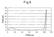
- FIG. 9 is a view showing a collision test of a plastic absorber and leg impactor.
- FIG. 10 is a detailed view of a metal absorber.
- FIG. 11 is a cross-sectional view of a metal absorber of another invention example.
- FIG. 12 is a view showing the range of tensile strength and sheet thickness of a material.
- FIG. 13 is a view showing the range of yield strength and sheet thickness of a material.
- FIG. 14 is a cross-sectional view of a metal absorber of another invention example.
- FIG. 15 is a view showing a method of production of a metal absorber.
- FIG. 16 is a view showing a collision test between an absorber of the present invention and a leg impactor.
- FIG. 17 is a view showing deformation of a metal absorber (center cross-section of length of 1 ⁇ 2 of left-right direction).
- FIG. 18 is a view showing deformation of a plastic absorber (center cross-section of 1 ⁇ 2 length of left-right direction).
- FIG. 19 is a view of the relationship between a force and stroke at the time of a collision.
- FIG. 20 are views showing deformation of an absorber with no bent parts at the top web and bottom web, wherein (a) shows a state before collision and (b) shows a state after collision.
- FIG. 21 is a view of the relationship between a force and stroke at the time of a collision of an absorber with no bent parts at the top web and bottom web.
- FIG. 22 are views for explaining arrangements of beads, wherein (a) is a view showing an absorber arranging beads of the top web and bottom web offset by half a wavelength so that projecting beads and recessed beads do not face each other.
- (b) is a view showing an absorber arranging beads of the top web and bottom web so that projecting beads and recessed beads face each other.
- FIG. 23 are views for explaining the arrangement of the beads and the relationship of a force and stroke at the time of collision, in which (a) is a view showing the relationship of a force and stroke at the time of collision of an absorber arranging the beads of the top web and bottom web offset by half a wavelength so that projecting beads and recessed beads do not face each other.
- (b) is a view showing the relationship of a force and stroke at the time of collision of an absorber arranging the beads of the top web and bottom web so that projecting beads and recessed beads face each other.
- the metal absorber according to the present invention may also be used along for a guard rail etc, but as shown by the outline when attaching a metal absorber 1 of the present invention to a reinforcement 2 in FIG. 1 , one having a length of the chassis width direction and provided between a bumper fascia arranged at the front (not shown) and a reinforcement 2 arranged at the rear is preferable.
- This metal absorber is an approximately hat shape formed by pressing steel sheet. Its opening part is provided flaring out toward the rear direction of the chassis.
- the metal absorber according to the present invention comprises a center flange 0201 , a top web 0204 and bottom web 0205 formed connected to its two ends, and a top flange 0202 and bottom flange 0203 respectively formed connected from the ends of the top web 0204 and bottom web 0205 at the opposite side to the center flange 0201 . It is formed integrally from steel sheet.
- an internal angle ⁇ 1 formed by the top web 0204 with the flange plane 0208 including the top flange 0202 and bottom flange 0203 about an intersection 0206 of the top web 0204 and top flange 0202 and an internal angle ⁇ 2 formed by the bottom web 0205 with the flange plane 0208 about an intersection 0207 of the bottom web 0205 and bottom flange 0203 are respectively made over 0 degree to less than 90 degrees.
- both ⁇ 1 and ⁇ 2 respectively must exceed 0 degree, preferably are at least 45 degrees, more preferably are at least 60 degrees. This is because if ⁇ 1 and ⁇ 2 are less than 45 degrees, the member cross-section will end up collapsing without the top web and the bottom web plastically deforming.
- angles are defined as less than 90 degrees, preferably are made 85 degrees or less.
- the absorber by making it flare out as explained above, and by providing one or both of the top web and bottom web with a recessed or projecting bead substantially parallel to the front-back direction of the vehicle, no matter what the position of the absorber a pedestrian is collided with, overall buckling easily occurs preferentially, so the impact energy can be absorbed without inflicting serious damage to the leg of the pedestrian.
- FIGS. 7 and 8 The result is shown in FIGS. 7 and 8 .
- the absorber folds outward from the bent parts and the member cross-section as a whole starts to buckle.
- the adjoining beads successively are crushed. The force is handled by the crushing of the beads.
- the end period of the collision FIG. 8( d )
- deformation of the member ends with no residual crush. Even if the vehicle collides at a speed of 40 km/hr, the force acting on the impactor can be maintained large (10 kN or more) and stroke of the impactor can be kept to 50 mm or less.
- top web and bottom web having recessed beads substantially parallel to the front-back direction of the chassis, but as shown in FIG. 2 , by providing one or both of the top web 0204 and the bottom web 0205 with recessed beads 7 - 1 or projecting beads 7 - 2 substantially parallel with the front-back direction of the chassis (see FIG. 10 ) over the entire surfaces, no matter where at the front surface of the vehicle a vehicle and a pedestrian collide, the beads buckle.
- the automobile bumper absorber of the present invention is made using steel sheet, aluminum, titanium, or another metal. By this, it is possible to absorb the impact energy along with plastic deformation of the metal, so the invention is limited to a metal.
- the angles ⁇ 1 and ⁇ 2 of one or both of the top web and bottom web of the metal absorber are changed in the middle.
- the angles are changed, as shown in FIG. 10 , so that the web projects out in the middle. That is, as shown in FIG. 11 , one or both of the top web 1101 and bottom web 1102 have bent parts 1103 , 1104 in the middle.
- the internal angle ⁇ 1 formed by the bent part 1103 of the top web 1101 with the plane parallel to the flange plane 1105 is made over 0 degree to less than ⁇ 1 degrees
- the internal angle ⁇ 2 formed by the bent part 1104 of the bottom web 1102 with the plane parallel to the flange plane is made over 0 degree to less than ⁇ 2 degrees.
- the internal angle ⁇ 1 of the bent part 1103 of the top web and the internal angle ⁇ 2 of the bent part 1104 of the bottom web are preferably made over 0 degree, more preferably at least 45 degrees and still more preferably at least 60 degrees.
- top web and the bottom web are preferably provided with bent parts at their middle parts so as to project outward.
- the aspect of the present invention according to (3) defines the width of the bead as H/5 to H/2.5 mm, the pitch as H/2.5 to H/1.25 mm, and the depth as H/50 to H/10 mm, where the front-back direction dimension of the absorber is H mm. If the width of the bead is smaller than H/5 mm, the cost of fabrication of the absorber deteriorates, while if over H/2.5 mm, when the collision position between the leg of the pedestrian and the absorber changes, the damage to the pedestrian's leg varies, so the width of the bead is preferably made H/5 to H/2.5 mm.
- the pitch of the bead is smaller than H/2.5 mm, the cost of fabrication of the absorber deteriorates, while if over H/1.25 mm, when the collision position between the leg of the pedestrian and the absorber changes, the damage to the pedestrian's leg varies, so the pitch of the bead is preferably made H/2.5 to H/1.25 mm.
- the depth of the bead is less than H/50 mm, the impact energy at the time of collision cannot be sufficiently absorbed. If over H/10 mm, the strength of the absorber becomes too high and the damage to the pedestrian's leg becomes larger, so the depth of the bead is preferably made H/50 to H/10 mm.
- the aspect of the present invention according to (4) is characterized by the arrangements of the beads at the top and bottom surfaces being offset by L/4 to L/2 mm at the top and bottom, where the pitch of the bead is L mm.
- FIG. 10 shows an example of offset by L/2 mm. If the offset of the bead arrangement is smaller than L/4 mm at the top and bottom, the damage to the pedestrian's leg varies when the collision position of the pedestrian's leg and absorber changes. Further, if over L/2 mm, similarly the damage to the pedestrian's leg varies when the collision position of the pedestrian's leg and absorber changes, so the length of offset of the bead arrangements at the top and bottom is preferably made L/4 to L/2 mm.
- the aspect of the present invention according to (5) is characterized by satisfying H/3 ⁇ W ⁇ H/1.5 mm where the maximum width of the top web 1101 and bottom web 1102 is W mm (see FIG. 11 ).
- the top or bottom web ends up buckling at a location close to the top or bottom flange and the force can no longer be maintained, so the maximum width W is preferably made at least H/3 mm.
- the maximum width W exceeds H/1.5 mm, the location of the top or bottom web close to the center flange buckles and the force can no longer be maintained, so the above range is preferable.
- the aspect of the present invention according to (6) is characterized by the tensile strength and sheet of the material satisfying the range of the solid line in FIG. 12 .
- the tensile strength and sheet thickness are in the bottom left region offset from the range shown by the solid line of FIG. 12 , the strength of the absorber is too low, so the impact can no longer be absorbed. If in the top right region, the strength of the absorber is too high, so the damage inflicted on the pedestrian's leg becomes larger. Therefore, the tensile strength and sheet thickness of the material of the absorber preferably satisfy the range of the solid line of FIG. 12 .
- the strength of the absorber may vary due to variations in the dimensions at the time of producing and working the material, so the range of the tensile strength and sheet thickness of the material is particularly preferably set within the range of the broken line 19 of FIG. 12 .
- “Within the range of the broken line 19 ” means within the range obtained by connecting the (x,y) points (0.2,1000), (0.2,600), (0.4,600), (0.4,200), (1.2,200), (1.2,400), (1.0,400), (1.0,600), (0.8,600), (0.8,800), (0.6,800), (0.6,1000), and (0.2,1000) by lines in an x-y orthogonal coordinate system having the tensile strength as the y-axis and the sheet thickness as the x-axis.
- the material of the absorber a steel sheet, it is possible to inexpensively and efficiently realize energy absorption by plastic deformation accompanying elongation.
- the aspect of the present invention according to (7) is characterized in that the yield strength and sheet thickness of the material satisfy the range of the solid line 1301 of FIG. 13 , particularly preferably satisfy the range of the broken line 1302 of FIG. 13 .
- the plastic deformation of a material depends on the yield strength, so the deformation is defined in relation to the yield strength. The detailed explanation is the same as with the aspect of the invention according to (6), so is omitted.
- the difference between ⁇ 1 and ⁇ 2 is preferably made 5 degrees or less.
- the aspect of the invention according to (9) is characterized by setting the upper limits of ⁇ 1 and ⁇ 2 to ⁇ 1 ⁇ 5 degrees and ⁇ 2 ⁇ 5 degrees respectively, and setting the lower limits of ⁇ 1 and ⁇ 2 to ⁇ 1 ⁇ 30 degrees and ⁇ 2 ⁇ 30 degrees respectively.
- the mode of deformation becomes one where the top and bottom surfaces of the member stably fold outward starting from the bent parts, so this is preferable.
- the lower limit of ⁇ 1 is ⁇ 1 ⁇ 30 degrees or more and the lower limit of ⁇ 2 is ⁇ 2 ⁇ 30 degrees or more, the top web and bottom web suitably plastically deform and the collapse of the member cross-section can be prevented, so this is preferable.
- the top web 1101 and the bottom web 1102 are provided with bent parts.
- the difference between ⁇ 1 and ⁇ 2 is preferably 5 degrees or less.
- ⁇ 1 ⁇ 2 .
- the internal angle ⁇ 1,n of the bent part 1404 of the top web and the internal angle ⁇ 2,n of the bent part 1406 of the bottom web are preferably made larger than 0 degree.
- ⁇ 1,n and ⁇ 2,n must be made smaller than the internal angles ⁇ 1,n-1 and ⁇ 2,n ⁇ 1 of the bent parts near the adjoining top flange or bottom flange, that is, near the flange plane 1407 .
- the internal angles ⁇ 1,n-1 and ⁇ 2,n ⁇ 1 are preferably smaller than ⁇ 1 and ⁇ 2 .
- the difference between ⁇ 1,n and ⁇ 2,n is preferably 5 degrees or less.
- ⁇ 1,n ⁇ 2,n .
- the aspect of the invention according to (13) is characterized by providing a bent part in the region of 0.3H to 0.7H mm from the top flange or the bottom flange in the front-back direction of the chassis, where the front-back direction dimension of the absorber is H mm.
- the bent part at a region of 0.3H mm or more from the top flange or the bottom flange in the front-back direction of the chassis (toward the center flange).
- the position of provision of the bent part exceeds 0.7H mm from the top flange or bottom flange in the front-back direction of the chassis (toward the center flange)
- the top web and bottom web buckle at positions near the top flange and bottom flange and the member cross-section as a whole collapses, so it is preferable to provide the bent part in the above range.
- the aspect of the invention according to (14) is characterized in that the vehicular metal bumper is an automobile metal bumper.
- the aspect of the invention according to (15) is characterized in that when making an impactor having a diameter of 70 mm, a length of 200 mm, and a mass of 8 kg collide with the absorber according to the aspects of the invention of the above (1) to (14) at an initial speed of 40 km/hr, the maximum force acting on the impactor is 2 kN to 12 kN, the force acting on the impactor is substantially constant, and the front-back direction dimension of the absorber required until the impactor stops is 50 mm or less.
- the maximum force acting on the impactor becomes 2 kN to 12 kN and an absorber preferable for protection of pedestrians can be obtained.
- the force acting on the impactor becomes substantially uniform, so the effects can be obtained that the impact energy can be efficiently absorbed by a compact member and the member can be made light in weight.
- the pedestrian's leg can be prevented from being broken and the damage given to the pedestrian's legs can be kept to a minimum.
- the aspect of the present invention according to (16) is an automobile bumper system providing a fascia and reinforcement before and after the automobile bumper absorber as set forth in any one of the above (1) to (5).
- the fascia and reinforcement are not particularly limited. Known parts may be used.
- the bead part preferentially buckles and absorbs the impact energy, so the pedestrian's leg can be protected.
- the metal absorber 1 As shown by the outline when attaching an automobile bumper absorber of the present invention to a reinforcement in FIG. 1 , the metal absorber 1 according to the present invention has a length of the amount of the chassis width direction and is provided between a bumper fascia arranged at the front (not shown) and a reinforcement 2 arranged at the rear.
- the metal absorber forms an approximately hat shape obtained by press forming steel sheet.
- the opening part is provided to flare outward toward the rear direction of the chassis. “Toward the rear direction of the chassis” means, with respect to the bumper fascia arranged at the front side, toward the chassis direction at the opposite side to the bumper fascia. Therefore, even when attached to the rear bumper, the opening part is provided flaring outward toward the chassis direction at the opposite side to the bumper fascia.
- the absorber By making the absorber a metal and by making it flare outward, overall buckling easily occurs preferentially, so the impact energy can be absorbed without giving serious damage to the leg of the pedestrian.
- the recessed bead 7 - 1 or projecting bead 7 - 2 substantially parallel to the front-back direction of the chassis at the top and bottom surfaces as a whole, even if an automobile and pedestrian collide with each other at some location of the front surface of the automobile, the beads will buckle, so even an absorber using a metal sheet with a small sheet thickness will be able to absorb greater impact energy, the absorber can be lightened in weight, and the pedestrian's leg can be protected.
- the automobile bumper absorber according to the present invention By making the automobile bumper absorber according to the present invention out of steel sheet, aluminum, titanium, or another metal, it is possible to absorb the impact energy accompanying the plastic deformation of the metal, so the invention is limited to a metal.
- the aspect of the present invention according to (18) is characterized in that the flaring angle of the top and bottom surfaces of the metal absorber changes in the middle.
- the angle is made to change so that, as shown in FIG. 1 and FIG. 10 , projections (peaks) are formed in the middle.
- the aspect of the present invention according to (19) defines the width of the bead as H/5 to H/2.5 mm, the pitch as H/2.5 to H/1.25 mm, and the depth as H/50 to H/10 mm when the front-back direction dimension of the absorber is H mm).
- the detailed explanation is the same as with the aspect of the invention according to (3), so is omitted.
- the aspect of the present invention according to (20) is characterized by the arrangements of the beads at the top and bottom surfaces being offset by L/4 to L/2 mm above and below, where the pitch of the bead is L mm.
- the detailed explanation is the same as with the aspect of the invention according to (4), so is omitted.
- the aspect of the present invention according to (21) is characterized by the tensile strength and sheet thickness of the material satisfying the range of the solid line of FIG. 12 .
- the detailed explanation is the same as with the aspect of the invention according to (6), so is omitted.
- the aspect of the present invention according to (22) is an automobile bumper system providing a fascia and reinforcement before and after the automobile bumper absorber as set forth in any one of the above (17) to (21).
- the detailed explanation is the same as with the aspect of the invention according to (16), so is omitted.
- recessed and projecting die tools 15 , 16 were used to press form the metal sheet 17 and transfer the die tool shape to the metal sheet to produce the absorber.
- the die tools were fabricated by machining a steel material. In their surfaces, beads similar to the absorber shape of the present invention were cut. These die tools were attached to a bed and slide of a press machine, then a metal sheet 17 was placed between the recessed and projecting die tools 15 , 16 and pressed from above and below. To secure formability by the shape and material of the absorber, sometimes a pad (not shown) is placed at the center part of the recessed die tool 15 and the front end of the absorber is pushed by a certain pressure.
- Forming method A die tool shown in FIG. 15 was used to press the sheet into an approximately hat shape.
- a solid plastic absorber using plastic foam (polypropylene) (top-bottom dimension of 90 mm, front-back dimension of 90 mm, and left-right dimension of 500 mm) was tested. Except for providing the top web and bottom web with bent parts at positions of 45 mm in the front-back direction and making the top-bottom dimension, front-back dimension, and left-right direction the above values, the dimensions were made the same as the above invention example.
- the impact was analyzed by numerical analysis using the finite element method.
- an impactor 8 simulating a pedestrian leg (diameter of 70 mm, length of 200 mm, and mass of 8 kg) was made to collide with the absorber at an initial speed of 40 km/hr and the trends in the force acting on the impactor at the time of collision (force-stroke relationship) and the state of deformation of the absorber were confirmed.
- FIG. 17 and FIG. 18 show the states of metal and plastic absorbers after deformation.
- the metal absorber is crushed to become broader in the vertical direction and has little residual crush ( FIG. 17 ).
- FIG. 18 in a plastic absorber, the plastic material cannot flow out compared with the initial shape 11 even after collision and has large residual crush (see deformed shape 12 of FIG. 18 ).
- FIG. 19 shows the force-stroke relationship at the time of collision.
- the metal absorber absorbs the impact by a short stroke (see FIG. 19 , line 13 ), while the plastic absorber requires a long stroke for impact absorption (see FIG. 19 , line 14 ).
- Forming method Pressed to an approximately hat shape.
- the impact was analyzed by numerical analysis using the finite element method.
- an impactor 8 simulating a pedestrian leg (diameter of 70 mm, length of 200 mm, and mass of 8 kg) was made to collide with the absorber at an initial speed of 40 km/hr and the trends in the force acting on the impactor at the time of collision (force-stroke relationship) and the state of deformation of the absorber were confirmed.
- FIG. 20( b ) shows the state of the absorber after deformation.
- the absorber was crushed with the top web is folded downward and the bottom web folded upward.
- FIG. 21 shows the force-stroke relationship at the time of collision. At the stage of the initial period of collision, the force rapidly rose, then immediately fell. After that, the force gradually continued to rise. In the latter period of the collision, a large force was generated and the impact energy was absorbed. In this example, the top and bottom flanges folded inward, so residual crush occurred and the force rose and fell.
- a plastic absorber see FIG.
- the force which the impactor absorbed increased, the front-back direction dimension of the absorber required until the impactor stopped could be made 50 mm or less, and the absorber could be confirmed effective to a certain extent for absorption of impact energy.
- the metal absorber alone, the target maximum force is liable to be exceeded and the pedestrian's leg to be damaged, but if jointly using an elastic member or other buffer member, pedestrian protection can also be realized.
- Forming method A die tool shown in FIG. 15 was used to press the sheet into an approximately hat shape shown in FIG. 22( a ).
- the impact was analyzed by numerical analysis using the finite element method.
- an impactor 8 simulating a pedestrian leg (diameter of 70 mm, length of 200 mm, and mass of 8 kg) was made to collide with the absorber at an initial speed of 40 km/hr and the trends in the force acting on the impactor at the time of collision (force-stroke relationship) and the state of deformation of the absorber were confirmed.
- the impactor collision position was made the bead center and bead boundary and the change in performance due to the impactor collision position was confirmed.
- FIG. 23 shows the relationship of the force and stroke at the time of collision.
- FIG. 23( a ) When there is offset between the top and bottom beads, similar force-stroke characteristics are exhibited regardless of the collision position ( FIG. 23( a )), but when there is no offset between the top and bottom beads, the force at the initial period of the collision becomes extremely large when the bead center is impacted (see FIG. 23( b ), line 2304 ). While the force-stroke characteristic varies depending on the collision position, compared with a plastic absorber (see FIG.
- the force which the impactor absorbs increases and further the front-back direction dimension of the absorber required until the impactor stops can be made 50 mm or less.
- the examples could be confirmed to be effective to a certain extent in absorbing impact energy and protecting the leg of the pedestrian.
- the hat-shaped metal absorber is crushed to spread in the vertical direction, whereby the impact energy received from the leg of the pedestrian is efficiently absorbed by a short stroke and residual crush becomes smaller, so the leg of the pedestrian can be protected by the smallest member dimension.
- the impact energy when colliding with a pedestrian at a speed of 40 km/hr, it is possible to absorb the impact energy by a stroke of 50 mm or less and protect the leg of the pedestrian.
Landscapes
- Engineering & Computer Science (AREA)
- Mechanical Engineering (AREA)
- Vibration Dampers (AREA)
- Body Structure For Vehicles (AREA)
Applications Claiming Priority (5)
| Application Number | Priority Date | Filing Date | Title |
|---|---|---|---|
| JP2007084128 | 2007-03-28 | ||
| JP2007-084128 | 2007-03-28 | ||
| JP2008077278A JP4330652B2 (ja) | 2007-03-28 | 2008-03-25 | 車両用金属製アブソーバ、車両用バンパシステム、自動車バンパ用アブソーバ及び自動車バンパシステム |
| JP2008-077278 | 2008-03-25 | ||
| PCT/JP2008/056740 WO2008117896A1 (ja) | 2007-03-28 | 2008-03-28 | 車両用金属製アブソーバ、車両用バンパシステム、自動車バンパ用アブソーバ及び自動車バンパシステム |
Publications (2)
| Publication Number | Publication Date |
|---|---|
| US20100066106A1 US20100066106A1 (en) | 2010-03-18 |
| US8419090B2 true US8419090B2 (en) | 2013-04-16 |
Family
ID=39788623
Family Applications (1)
| Application Number | Title | Priority Date | Filing Date |
|---|---|---|---|
| US12/450,454 Expired - Fee Related US8419090B2 (en) | 2007-03-28 | 2008-03-28 | Vehicular metal absorber, vehicular bumper system, automobile bumper absorber, and automobile bumper system |
Country Status (9)
| Country | Link |
|---|---|
| US (1) | US8419090B2 (zh) |
| EP (1) | EP2130724B1 (zh) |
| JP (1) | JP4330652B2 (zh) |
| KR (1) | KR101118828B1 (zh) |
| CN (1) | CN101641240B (zh) |
| BR (1) | BRPI0809357A2 (zh) |
| ES (1) | ES2604762T3 (zh) |
| MX (1) | MX2009009684A (zh) |
| WO (1) | WO2008117896A1 (zh) |
Cited By (3)
| Publication number | Priority date | Publication date | Assignee | Title |
|---|---|---|---|---|
| US20110057462A1 (en) * | 2009-09-08 | 2011-03-10 | Dr. Ing. H.C.F. Porsche Aktiengesellschaft | Bumper and bumper construction kit |
| CN106427843A (zh) * | 2015-08-06 | 2017-02-22 | 丰田自动车株式会社 | 车身框架构造 |
| WO2024091269A1 (en) * | 2022-10-28 | 2024-05-02 | Atieva, Inc. | Stamped energy absorption side structure for vehicle |
Families Citing this family (31)
| Publication number | Priority date | Publication date | Assignee | Title |
|---|---|---|---|---|
| DE102008057881A1 (de) * | 2008-11-18 | 2010-05-27 | Audi Ag | Stoßfänger für ein Kraftfahrzeug |
| JP5471773B2 (ja) * | 2010-04-26 | 2014-04-16 | トヨタ自動車株式会社 | バンパ構造 |
| US9238443B2 (en) | 2010-12-17 | 2016-01-19 | Sabic Global Technologies B.V. | Blow molded energy absorber and systems and methods of making and using the same |
| CN103338977B (zh) * | 2011-03-16 | 2016-02-03 | 铃木株式会社 | 车辆前部用吸收体结构 |
| MY158383A (en) * | 2011-03-30 | 2016-09-26 | Nippon Steel & Sumitomo Metal Corp | Metallic hollow columnar member |
| MX345043B (es) * | 2011-05-20 | 2017-01-16 | Nippon Steel & Sumitomo Metal Corp | Método de moldeo por presión y componente de vehículo. |
| US20130175128A1 (en) * | 2012-01-05 | 2013-07-11 | Sabic Innovative Plastics Ip B.V. | Multi-stage energy absorber and method of making and using the same |
| JP5880838B2 (ja) * | 2012-01-30 | 2016-03-09 | 三菱自動車工業株式会社 | 車両のバンパ構造 |
| JP5953887B2 (ja) | 2012-04-02 | 2016-07-20 | マツダ株式会社 | 車両の車体前部構造 |
| WO2013172137A1 (ja) * | 2012-05-15 | 2013-11-21 | 日産自動車株式会社 | 衝撃吸収部材 |
| JP5987638B2 (ja) * | 2012-10-31 | 2016-09-07 | マツダ株式会社 | 車両の車体構造 |
| SE537087C2 (sv) * | 2013-03-13 | 2014-12-30 | Gestamp Hardtech Ab | Stötfångarbalk |
| CN103287381B (zh) * | 2013-06-18 | 2016-01-20 | 延锋彼欧汽车外饰系统有限公司 | 一种汽车的吸能装置 |
| CN103754189B (zh) * | 2014-01-23 | 2016-03-16 | 奇瑞汽车股份有限公司 | 汽车用行人上腿部保护装置及汽车 |
| JP2016052859A (ja) * | 2014-09-04 | 2016-04-14 | 豊田鉄工株式会社 | 車両用バンパービーム |
| JP6170895B2 (ja) * | 2014-10-22 | 2017-07-26 | 株式会社神戸製鋼所 | 自動車用耐衝突部品 |
| DE102015111995B4 (de) * | 2015-07-23 | 2017-11-02 | Benteler Automobiltechnik Gmbh | Stoßfängeranordnung mit Schließplatte |
| JP6531662B2 (ja) * | 2016-02-17 | 2019-06-19 | スズキ株式会社 | 車体前部構造 |
| JP6384562B2 (ja) * | 2017-03-27 | 2018-09-05 | マツダ株式会社 | 車両の車体前部構造 |
| WO2020085381A1 (ja) | 2018-10-24 | 2020-04-30 | 日本製鉄株式会社 | 自動車骨格部材および電気自動車 |
| EP3848273B1 (en) | 2018-10-24 | 2024-03-13 | Nippon Steel Corporation | Automobile structural member |
| DE102018129724B4 (de) * | 2018-11-26 | 2022-08-04 | Benteler Automobiltechnik Gmbh | Fahrzeugbauteil für ein Fahrzeug |
| CN109733309A (zh) * | 2019-02-28 | 2019-05-10 | 延锋彼欧汽车外饰系统有限公司 | 一种用于汽车前端的m型吸能盒结构及其总成 |
| JP7120175B2 (ja) * | 2019-07-18 | 2022-08-17 | Jfeスチール株式会社 | 自動車用衝突エネルギー吸収部品、該自動車用衝突エネルギー吸収部品の製造方法 |
| US11505148B2 (en) | 2019-09-27 | 2022-11-22 | Nissan North America, Inc. | Vehicle reinforcement assembly |
| JP2021115978A (ja) * | 2020-01-27 | 2021-08-10 | トヨタ自動車株式会社 | バンパアブソーバ |
| US20230271649A1 (en) * | 2020-07-31 | 2023-08-31 | Nippon Steel Corporation | Structural member for automobile body |
| US20230278634A1 (en) | 2020-07-31 | 2023-09-07 | Nippon Steel Corporation | Structural member of vehicle body |
| JP7358307B2 (ja) * | 2020-08-11 | 2023-10-10 | 豊田鉄工株式会社 | 車両用構造部材 |
| CN112231827A (zh) * | 2020-09-22 | 2021-01-15 | 一汽奔腾轿车有限公司 | 一种汽车外观尺寸感知质量评价方法 |
| JP7213229B2 (ja) * | 2020-12-16 | 2023-01-26 | 本田技研工業株式会社 | 歩行者保護装置 |
Citations (18)
| Publication number | Priority date | Publication date | Assignee | Title |
|---|---|---|---|---|
| JPH07205732A (ja) | 1994-01-13 | 1995-08-08 | Yamakawa Ind Co Ltd | バンパーリインホースとその製造方法 |
| WO1998011267A1 (en) | 1996-09-13 | 1998-03-19 | Peter Benson | A beam-shaped object such as a beam for a bumper and the like |
| JPH10175020A (ja) | 1996-12-16 | 1998-06-30 | Shimizu Kikai Kk | ロール成形装置 |
| KR19980068371A (ko) | 1997-02-18 | 1998-10-15 | 남재일 | 도로의 미끄럼 방지용 골재의 제조방법과 시공방법 |
| WO2001002218A1 (fr) | 1999-07-05 | 2001-01-11 | Peugeot Citroen Automobiles Sa | Poutre de pare-chocs pour vehicules automobiles |
| US6416094B1 (en) * | 2001-07-27 | 2002-07-09 | Talfourd-Jones Inc. | Energy absorbing bumper |
| US6510771B2 (en) * | 1998-05-19 | 2003-01-28 | Shape Corporation | Die apparatus for cutting end of bumper bar |
| WO2004011306A1 (en) | 2002-07-30 | 2004-02-05 | Netshape Corporation | Bumper for reducing pedestrian injury |
| WO2004018261A1 (en) | 2002-08-23 | 2004-03-04 | General Electric Company | Pedestrian energy absorber for automotive vehicles |
| JP2004232042A (ja) | 2003-01-31 | 2004-08-19 | Allied Material Corp | 硬質合金 |
| JP2004322861A (ja) | 2003-03-04 | 2004-11-18 | Jsp Corp | バンパー構造 |
| US6877785B2 (en) * | 2001-04-16 | 2005-04-12 | Netshape International, Llc | Bumper system with face-mounted energy absorber |
| JP2005178695A (ja) | 2003-12-24 | 2005-07-07 | Aisin Takaoka Ltd | 車輌用衝突補強材 |
| US20050248164A1 (en) | 2004-05-07 | 2005-11-10 | Honda Motor Co., Ltd. | Vehicle body frontal structure |
| JP2006023204A (ja) | 2004-07-08 | 2006-01-26 | Hitachi Ltd | 移動体異常検知システム |
| US6997490B2 (en) * | 2003-07-22 | 2006-02-14 | Netshape International Llc | Integrated bumper energy absorber and fascia support component |
| JP2006232042A (ja) | 2005-02-24 | 2006-09-07 | Fuji Heavy Ind Ltd | 車両の前部構造 |
| US20070024069A1 (en) * | 2005-08-01 | 2007-02-01 | Katsutoshi Takagi | Bumper beam for vehicle |
Family Cites Families (1)
| Publication number | Priority date | Publication date | Assignee | Title |
|---|---|---|---|---|
| KR19980068371U (ko) * | 1997-05-31 | 1998-12-05 | 양재신 | 자동차의 범퍼 취부구조 |
-
2008
- 2008-03-25 JP JP2008077278A patent/JP4330652B2/ja active Active
- 2008-03-28 CN CN2008800098695A patent/CN101641240B/zh not_active Expired - Fee Related
- 2008-03-28 WO PCT/JP2008/056740 patent/WO2008117896A1/ja active Application Filing
- 2008-03-28 US US12/450,454 patent/US8419090B2/en not_active Expired - Fee Related
- 2008-03-28 KR KR1020097020017A patent/KR101118828B1/ko not_active IP Right Cessation
- 2008-03-28 EP EP08739847.5A patent/EP2130724B1/en not_active Not-in-force
- 2008-03-28 MX MX2009009684A patent/MX2009009684A/es active IP Right Grant
- 2008-03-28 ES ES08739847.5T patent/ES2604762T3/es active Active
- 2008-03-28 BR BRPI0809357-1A patent/BRPI0809357A2/pt not_active Application Discontinuation
Patent Citations (22)
| Publication number | Priority date | Publication date | Assignee | Title |
|---|---|---|---|---|
| JPH07205732A (ja) | 1994-01-13 | 1995-08-08 | Yamakawa Ind Co Ltd | バンパーリインホースとその製造方法 |
| WO1998011267A1 (en) | 1996-09-13 | 1998-03-19 | Peter Benson | A beam-shaped object such as a beam for a bumper and the like |
| JPH10175020A (ja) | 1996-12-16 | 1998-06-30 | Shimizu Kikai Kk | ロール成形装置 |
| KR19980068371A (ko) | 1997-02-18 | 1998-10-15 | 남재일 | 도로의 미끄럼 방지용 골재의 제조방법과 시공방법 |
| US6510771B2 (en) * | 1998-05-19 | 2003-01-28 | Shape Corporation | Die apparatus for cutting end of bumper bar |
| US6371540B1 (en) * | 1999-05-07 | 2002-04-16 | Peugeot Citröen {overscore (A)}utomobiles S.A. | Bumper beam for motor vehicles |
| WO2001002218A1 (fr) | 1999-07-05 | 2001-01-11 | Peugeot Citroen Automobiles Sa | Poutre de pare-chocs pour vehicules automobiles |
| JP2003503272A (ja) | 1999-07-05 | 2003-01-28 | プジョー・シトロエン・オトモビル・ソシエテ・アノニム | 自動車のバンパビーム |
| US6877785B2 (en) * | 2001-04-16 | 2005-04-12 | Netshape International, Llc | Bumper system with face-mounted energy absorber |
| US6416094B1 (en) * | 2001-07-27 | 2002-07-09 | Talfourd-Jones Inc. | Energy absorbing bumper |
| WO2004011306A1 (en) | 2002-07-30 | 2004-02-05 | Netshape Corporation | Bumper for reducing pedestrian injury |
| JP2005534555A (ja) | 2002-07-30 | 2005-11-17 | ネットシェイプ・コーポレイション | 歩行者の負傷を軽減するバンパー |
| WO2004018261A1 (en) | 2002-08-23 | 2004-03-04 | General Electric Company | Pedestrian energy absorber for automotive vehicles |
| JP2005536392A (ja) | 2002-08-23 | 2005-12-02 | ゼネラル・エレクトリック・カンパニイ | 自動車の歩行者用エネルギ吸収体 |
| JP2004232042A (ja) | 2003-01-31 | 2004-08-19 | Allied Material Corp | 硬質合金 |
| JP2004322861A (ja) | 2003-03-04 | 2004-11-18 | Jsp Corp | バンパー構造 |
| US6997490B2 (en) * | 2003-07-22 | 2006-02-14 | Netshape International Llc | Integrated bumper energy absorber and fascia support component |
| JP2005178695A (ja) | 2003-12-24 | 2005-07-07 | Aisin Takaoka Ltd | 車輌用衝突補強材 |
| US20050248164A1 (en) | 2004-05-07 | 2005-11-10 | Honda Motor Co., Ltd. | Vehicle body frontal structure |
| JP2006023204A (ja) | 2004-07-08 | 2006-01-26 | Hitachi Ltd | 移動体異常検知システム |
| JP2006232042A (ja) | 2005-02-24 | 2006-09-07 | Fuji Heavy Ind Ltd | 車両の前部構造 |
| US20070024069A1 (en) * | 2005-08-01 | 2007-02-01 | Katsutoshi Takagi | Bumper beam for vehicle |
Non-Patent Citations (5)
| Title |
|---|
| European Enhanced Vehicle-safety Committee, "Improved Test Methods to Evaluate Pedestrian Protection Afforded by Passenger Cars", EEVC Working Group 17 Report, Dec. 1998. |
| International Search Report dated May 27, 2008 issued in corresponding PCT Application No. PCT/JP2008/056740. |
| Japanese Office Action dated Jan. 20, 2009 issued in corresponding Japanese Application No. 2008-077278. |
| Office Action issued on Mar. 2, 2011 in the corresponding Korean Application No. 1998-68371. |
| Supplementary European Search Report dated Jun. 4, 2010 issued in corresponding European Application No. EP 08 73 9847. |
Cited By (3)
| Publication number | Priority date | Publication date | Assignee | Title |
|---|---|---|---|---|
| US20110057462A1 (en) * | 2009-09-08 | 2011-03-10 | Dr. Ing. H.C.F. Porsche Aktiengesellschaft | Bumper and bumper construction kit |
| CN106427843A (zh) * | 2015-08-06 | 2017-02-22 | 丰田自动车株式会社 | 车身框架构造 |
| WO2024091269A1 (en) * | 2022-10-28 | 2024-05-02 | Atieva, Inc. | Stamped energy absorption side structure for vehicle |
Also Published As
| Publication number | Publication date |
|---|---|
| CN101641240B (zh) | 2012-10-24 |
| ES2604762T3 (es) | 2017-03-09 |
| MX2009009684A (es) | 2009-10-07 |
| EP2130724A1 (en) | 2009-12-09 |
| WO2008117896A1 (ja) | 2008-10-02 |
| BRPI0809357A2 (pt) | 2014-09-02 |
| EP2130724A4 (en) | 2010-07-07 |
| JP4330652B2 (ja) | 2009-09-16 |
| JP2008265738A (ja) | 2008-11-06 |
| KR101118828B1 (ko) | 2012-03-20 |
| US20100066106A1 (en) | 2010-03-18 |
| EP2130724B1 (en) | 2016-08-31 |
| CN101641240A (zh) | 2010-02-03 |
| KR20090115881A (ko) | 2009-11-09 |
Similar Documents
| Publication | Publication Date | Title |
|---|---|---|
| US8419090B2 (en) | Vehicular metal absorber, vehicular bumper system, automobile bumper absorber, and automobile bumper system | |
| KR101717511B1 (ko) | 유니타리 에너지 흡수 조립체 및 이의 제조 방법 | |
| EP1545937B1 (en) | Bumper for reducing pedestrian injury | |
| US6851731B2 (en) | Crash energy absorbing element | |
| JP2004148915A (ja) | 車両用バンパ装置 | |
| US8104804B2 (en) | Automobile safety bumper assembly | |
| KR101660429B1 (ko) | 엇갈린, 수직 배향 크러쉬 로브들을 구비한 에너지 완충기 | |
| JP2010042753A (ja) | バンパーリインフォースメントおよびその製造方法 | |
| JP4787728B2 (ja) | 車体バンパービームおよび車体用衝撃緩衝部材 | |
| JP5311762B2 (ja) | エネルギー吸収部材 | |
| JP5011516B2 (ja) | 車両用衝撃吸収体 | |
| EP1262374B1 (en) | Crash energy absorbing element | |
| JP4162958B2 (ja) | 衝撃緩衝部材 | |
| JP4967523B2 (ja) | 衝撃吸収部材 | |
| JP4457302B2 (ja) | 自動車用衝撃吸収部材 | |
| KR101369725B1 (ko) | 차량용 크래쉬박스 | |
| KR101795070B1 (ko) | 보행자 상해 보호장치 | |
| KR20120118276A (ko) | 차량용 크래쉬박스 | |
| JP5067493B1 (ja) | 車両用バンパ装置 | |
| CN109591749A (zh) | 吸能装置及车辆 | |
| KR101057985B1 (ko) | 차량용 범퍼유닛 | |
| KR101336589B1 (ko) | 차량용 어퍼 스티프너 | |
| CN208277997U (zh) | 一种具有刚度补偿功能的防撞梁缓冲结构 | |
| JP4117543B2 (ja) | 衝撃吸収部材 | |
| CN205022703U (zh) | 一种汽车门槛的吸能盒结构 |
Legal Events
| Date | Code | Title | Description |
|---|---|---|---|
| AS | Assignment |
Owner name: UNIPRES CORPORATION,JAPAN Free format text: ASSIGNMENT OF ASSIGNORS INTEREST;ASSIGNORS:NOJIMA, KOJI;SATSUKAWA, ISAO;ARIGA, TAKASHI;AND OTHERS;REEL/FRAME:023311/0258 Effective date: 20090727 Owner name: NIPPON STEEL CORPORATION,JAPAN Free format text: ASSIGNMENT OF ASSIGNORS INTEREST;ASSIGNORS:NOJIMA, KOJI;SATSUKAWA, ISAO;ARIGA, TAKASHI;AND OTHERS;REEL/FRAME:023311/0258 Effective date: 20090727 Owner name: NIPPON STEEL CORPORATION, JAPAN Free format text: ASSIGNMENT OF ASSIGNORS INTEREST;ASSIGNORS:NOJIMA, KOJI;SATSUKAWA, ISAO;ARIGA, TAKASHI;AND OTHERS;REEL/FRAME:023311/0258 Effective date: 20090727 Owner name: UNIPRES CORPORATION, JAPAN Free format text: ASSIGNMENT OF ASSIGNORS INTEREST;ASSIGNORS:NOJIMA, KOJI;SATSUKAWA, ISAO;ARIGA, TAKASHI;AND OTHERS;REEL/FRAME:023311/0258 Effective date: 20090727 |
|
| AS | Assignment |
Owner name: UNIPRES CORPORATION,JAPAN Free format text: CORRECTIVE ASSIGNMENT TO CORRECT THE ADDRESS OF THE FIRST ASSIGNEE, UNIPRES CORPORATION, PREVIOUSLY RECORDED ON REEL 023311 FRAME 0258. ASSIGNOR(S) HEREBY CONFIRMS THE ADDRESS AS 5TH FLOOR, SUN HAMADA BLDG., 1-19-20, SHINYOKOHAMA, KOHOKU-KU, YOKOHAMA-SHI, KANAGAWA 222-8581, JAPAN;ASSIGNORS:NOJIMA, KOJI;SATSUKAWA, ISAO;ARIGA, TAKASHI;AND OTHERS;REEL/FRAME:023622/0900 Effective date: 20090727 Owner name: NIPPON STEEL CORPORATION,JAPAN Free format text: CORRECTIVE ASSIGNMENT TO CORRECT THE ADDRESS OF THE FIRST ASSIGNEE, UNIPRES CORPORATION, PREVIOUSLY RECORDED ON REEL 023311 FRAME 0258. ASSIGNOR(S) HEREBY CONFIRMS THE ADDRESS AS 5TH FLOOR, SUN HAMADA BLDG., 1-19-20, SHINYOKOHAMA, KOHOKU-KU, YOKOHAMA-SHI, KANAGAWA 222-8581, JAPAN;ASSIGNORS:NOJIMA, KOJI;SATSUKAWA, ISAO;ARIGA, TAKASHI;AND OTHERS;REEL/FRAME:023622/0900 Effective date: 20090727 Owner name: NIPPON STEEL CORPORATION, JAPAN Free format text: CORRECTIVE ASSIGNMENT TO CORRECT THE ADDRESS OF THE FIRST ASSIGNEE, UNIPRES CORPORATION, PREVIOUSLY RECORDED ON REEL 023311 FRAME 0258. ASSIGNOR(S) HEREBY CONFIRMS THE ADDRESS AS 5TH FLOOR, SUN HAMADA BLDG., 1-19-20, SHINYOKOHAMA, KOHOKU-KU, YOKOHAMA-SHI, KANAGAWA 222-8581, JAPAN;ASSIGNORS:NOJIMA, KOJI;SATSUKAWA, ISAO;ARIGA, TAKASHI;AND OTHERS;REEL/FRAME:023622/0900 Effective date: 20090727 Owner name: UNIPRES CORPORATION, JAPAN Free format text: CORRECTIVE ASSIGNMENT TO CORRECT THE ADDRESS OF THE FIRST ASSIGNEE, UNIPRES CORPORATION, PREVIOUSLY RECORDED ON REEL 023311 FRAME 0258. ASSIGNOR(S) HEREBY CONFIRMS THE ADDRESS AS 5TH FLOOR, SUN HAMADA BLDG., 1-19-20, SHINYOKOHAMA, KOHOKU-KU, YOKOHAMA-SHI, KANAGAWA 222-8581, JAPAN;ASSIGNORS:NOJIMA, KOJI;SATSUKAWA, ISAO;ARIGA, TAKASHI;AND OTHERS;REEL/FRAME:023622/0900 Effective date: 20090727 |
|
| AS | Assignment |
Owner name: NIPPON STEEL & SUMITOMO METAL CORPORATION, JAPAN Free format text: MERGER;ASSIGNOR:NIPPON STEEL CORPORATION;REEL/FRAME:029822/0654 Effective date: 20121001 |
|
| STCF | Information on status: patent grant |
Free format text: PATENTED CASE |
|
| FEPP | Fee payment procedure |
Free format text: PAYOR NUMBER ASSIGNED (ORIGINAL EVENT CODE: ASPN); ENTITY STATUS OF PATENT OWNER: LARGE ENTITY |
|
| CC | Certificate of correction | ||
| FPAY | Fee payment |
Year of fee payment: 4 |
|
| FEPP | Fee payment procedure |
Free format text: MAINTENANCE FEE REMINDER MAILED (ORIGINAL EVENT CODE: REM.); ENTITY STATUS OF PATENT OWNER: LARGE ENTITY |
|
| LAPS | Lapse for failure to pay maintenance fees |
Free format text: PATENT EXPIRED FOR FAILURE TO PAY MAINTENANCE FEES (ORIGINAL EVENT CODE: EXP.); ENTITY STATUS OF PATENT OWNER: LARGE ENTITY |
|
| STCH | Information on status: patent discontinuation |
Free format text: PATENT EXPIRED DUE TO NONPAYMENT OF MAINTENANCE FEES UNDER 37 CFR 1.362 |
|
| FP | Lapsed due to failure to pay maintenance fee |
Effective date: 20210416 |