US8079122B2 - Spacer jig for replacing spacer damper of overhead power lines and method of replacing spacer damper using the same - Google Patents
Spacer jig for replacing spacer damper of overhead power lines and method of replacing spacer damper using the same Download PDFInfo
- Publication number
- US8079122B2 US8079122B2 US12/071,613 US7161308A US8079122B2 US 8079122 B2 US8079122 B2 US 8079122B2 US 7161308 A US7161308 A US 7161308A US 8079122 B2 US8079122 B2 US 8079122B2
- Authority
- US
- United States
- Prior art keywords
- spacer
- clamp
- hexahedron
- spacer jig
- rotational
- Prior art date
- Legal status (The legal status is an assumption and is not a legal conclusion. Google has not performed a legal analysis and makes no representation as to the accuracy of the status listed.)
- Expired - Fee Related, expires
Links
Images


Classifications
-
- H—ELECTRICITY
- H02—GENERATION; CONVERSION OR DISTRIBUTION OF ELECTRIC POWER
- H02G—INSTALLATION OF ELECTRIC CABLES OR LINES, OR OF COMBINED OPTICAL AND ELECTRIC CABLES OR LINES
- H02G7/00—Overhead installations of electric lines or cables
- H02G7/12—Devices for maintaining distance between parallel conductors, e.g. spacer
- H02G7/125—Damping spacers
-
- H—ELECTRICITY
- H02—GENERATION; CONVERSION OR DISTRIBUTION OF ELECTRIC POWER
- H02G—INSTALLATION OF ELECTRIC CABLES OR LINES, OR OF COMBINED OPTICAL AND ELECTRIC CABLES OR LINES
- H02G7/00—Overhead installations of electric lines or cables
- H02G7/14—Arrangements or devices for damping mechanical oscillations of lines, e.g. for reducing production of sound
-
- H—ELECTRICITY
- H02—GENERATION; CONVERSION OR DISTRIBUTION OF ELECTRIC POWER
- H02G—INSTALLATION OF ELECTRIC CABLES OR LINES, OR OF COMBINED OPTICAL AND ELECTRIC CABLES OR LINES
- H02G1/00—Methods or apparatus specially adapted for installing, maintaining, repairing or dismantling electric cables or lines
- H02G1/02—Methods or apparatus specially adapted for installing, maintaining, repairing or dismantling electric cables or lines for overhead lines or cables
-
- H—ELECTRICITY
- H02—GENERATION; CONVERSION OR DISTRIBUTION OF ELECTRIC POWER
- H02G—INSTALLATION OF ELECTRIC CABLES OR LINES, OR OF COMBINED OPTICAL AND ELECTRIC CABLES OR LINES
- H02G7/00—Overhead installations of electric lines or cables
- H02G7/05—Suspension arrangements or devices for electric cables or lines
- H02G7/053—Suspension clamps and clips for electric overhead lines not suspended to a supporting wire
-
- Y—GENERAL TAGGING OF NEW TECHNOLOGICAL DEVELOPMENTS; GENERAL TAGGING OF CROSS-SECTIONAL TECHNOLOGIES SPANNING OVER SEVERAL SECTIONS OF THE IPC; TECHNICAL SUBJECTS COVERED BY FORMER USPC CROSS-REFERENCE ART COLLECTIONS [XRACs] AND DIGESTS
- Y10—TECHNICAL SUBJECTS COVERED BY FORMER USPC
- Y10T—TECHNICAL SUBJECTS COVERED BY FORMER US CLASSIFICATION
- Y10T29/00—Metal working
- Y10T29/49—Method of mechanical manufacture
- Y10T29/49718—Repairing
- Y10T29/49721—Repairing with disassembling
- Y10T29/4973—Replacing of defective part
-
- Y—GENERAL TAGGING OF NEW TECHNOLOGICAL DEVELOPMENTS; GENERAL TAGGING OF CROSS-SECTIONAL TECHNOLOGIES SPANNING OVER SEVERAL SECTIONS OF THE IPC; TECHNICAL SUBJECTS COVERED BY FORMER USPC CROSS-REFERENCE ART COLLECTIONS [XRACs] AND DIGESTS
- Y10—TECHNICAL SUBJECTS COVERED BY FORMER USPC
- Y10T—TECHNICAL SUBJECTS COVERED BY FORMER US CLASSIFICATION
- Y10T29/00—Metal working
- Y10T29/53—Means to assemble or disassemble
- Y10T29/537—Means to assemble or disassemble tool handle and tool
-
- Y—GENERAL TAGGING OF NEW TECHNOLOGICAL DEVELOPMENTS; GENERAL TAGGING OF CROSS-SECTIONAL TECHNOLOGIES SPANNING OVER SEVERAL SECTIONS OF THE IPC; TECHNICAL SUBJECTS COVERED BY FORMER USPC CROSS-REFERENCE ART COLLECTIONS [XRACs] AND DIGESTS
- Y10—TECHNICAL SUBJECTS COVERED BY FORMER USPC
- Y10T—TECHNICAL SUBJECTS COVERED BY FORMER US CLASSIFICATION
- Y10T29/00—Metal working
- Y10T29/53—Means to assemble or disassemble
- Y10T29/53978—Means to assemble or disassemble including means to relatively position plural work parts
Definitions
- the present invention relates to a spacer jig for replacing the spacer damper, which is installed on a four-conductor or six-conductor system, which are formed a set of power cables, and a method for replacing the spacer damper by setting the spacer jig. More particularly, the spacer jig is used as a tool to replace a damaged or bad spacer damper with a new one during the maintenance of the overhead power lines for reducing the vibration problems.
- the worker travels high in the air with a new replacement spacer damper and installs it by temporarily assembling four conductors at a point 1 to 1.5 m away and six conductors about three m away from the spacer damper to be replaced, and then pushes this in close to the spacer damper.
- This process has a problem of taking a long time since it is difficult to separate the spacer damper and replace it with a new one because the surface of the cable is damaged and a high tensile force is on the cable when the worker pushes in the spacer damper.
- the worker In order to replace the existing damaged spacer damper, the worker is lifted high in the air with a new spacer damper, and temporarily assembles the new spacer damper at a location about one to three m away from the existing spacer damper.
- the existing spacer damper cannot be approached closely enough to be replaced and the worker cannot hold up or widen the relevant cables by hand because of the high tensile force of the cable.
- the worker holds up the relevant cable by hand at a location where a certain degree of modification is possible, that is, a location separated by a given distance from the damaged spacer damper, before he temporarily assembles the new spacer damper.
- the new spacer damper assembled temporarily like this should now be moved to the location of the existing spacer damper which is to be replaced. Since the location of the existing spacer damper was initially set up at the most suitable and efficient location with respect to the total length of overhead line, it is most preferable to install the new damper at the same location. Therefore, the new spacer damper is moved to and installed in the place where the existing spacer damper is located.
- spacer damper replacement work using a spacer jig is a required process for hot-line work.
- the length of the clamp shaft can be adjusted by using a wrench, and a rotating mount plate is provided between the clamp shaft and the clamp, so the clamp and cable are not twisted when the clamp shaft is rotated by the wrench.
- a snap locking lid is mounted on the edge of the clamp to grip the cable, so that the work is conveniently performed to quickly adjust the spacing of cables.
- a spacer jig is provided for replacing the spacer damper.
- the spacer jig has a structure comprising: a clamp provided with snap locking lid; a clamp shaft provided with a male thread; a clamp mounting unit for coupling the clamp shaft and the clamp; a stationary hexahedron nut with a female threaded is provided to mate with a male thread of the clamp shaft; a rotational hexahedron nut has a pair of disk shaped hinges protruded from front and rear surface to mount into a hinge hole on the frame so that the rotational hexahedron nut can be rotated; a grip ring installed at the end of the clamp shaft to be turned by hand; a hexagonal bolt head formed at the end of the clamp shaft for turning by wrench; and a frame has polygonal shape for mounting four or six clamp shafts.
- the clamp comprises: the clamp and the lid grip the cables on the overhead power lines by snap locking latch; and a clamp mounting unit for coupling the clamp and the clamp shaft by the rotating plate, so as to prevent the clamp and cables twisted from rotating of the clamp shaft.
- the clamp shaft comprises: a male thread; a grip ring for rotating by hand; and a hexagonal bolt head integrally formed at the tip for turning by a wrench.
- the stationary and rotational hexahedron nuts are arranged even interval in radial direction of the frame.
- a square shaped frame has three stationary hexahedron nuts and one rotational hexahedron nut for the four-conductor spacer jig.
- a hexagonal shaped frame has four stationary hexahedron nuts and two rotational hexahedron nuts for the six-conductor spacer jig, respectively.
- a method for replacing a new spacer damper by using the spacer jig of the present invention comprising the steps of: first install the spacer jig adjacent to the bad spacer damper, turning the clamp shaft of spacer jig to widen the spacing, then release the bad spacer damper from the cable, and remove the bad spacer damper from the four conductor or six conductor cables.
- FIG. 1 is a perspective view showing the disassembled state of a spacer jig for six conductors of the present invention.
- FIG. 2 is a perspective view showing the assembled state of the spacer jig according to the present invention.
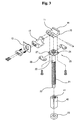
- FIG. 3 is a disassembled perspective view of the clamp shaft and clamp of the spacer jig according to the present invention.
- FIG. 4 is a sectional view showing the assembled state of the clamp and clamp shaft of the spacer jig according to the present invention.
- FIG. 5 is an operating diagram showing the rotating state of the clamp shaft of the spacer jig according to the present invention.
- FIG. 6 is an operating diagram showing the expanded state of the clamp shaft of the spacer jig according to the present invention.
- FIGS. 7A to 7C are drawings showing the process of replacing spacer dampers using the spacer jig of the present invention.
- FIG. 7A is a perspective view of an existing spacer damper installed on line.
- FIG. 7B is a perspective view showing the state where a spacer jig is installed in the location adjacent to the existing spacer damper.
- FIG. 7C is a perspective view showing the process of separating the existing spacer damper by expanding the clamp shafts of the spacer jig.
- FIG. 8 is an overall perspective view of the spacer jig for four conductors according to another embodiment.
- FIG. 1 is a perspective view showing the disassembled state of a spacer jig for six conductors according to a preferred embodiment of the present invention.
- FIG. 2 is a perspective view showing the assembled state of the spacer jig according to the present invention.
- FIG. 3 is a disassembled perspective view of the clamp shaft and clamp of the spacer jig according to the present invention.
- FIG. 4 is a sectional view showing the assembled state of the clamp and clamp shaft of the spacer jig according to the present invention.
- FIG. 5 is an operating diagram showing the rotating state of the clamp shaft of the spacer jig according to the present invention
- FIG. 6 is an operating diagram showing the expanded state of the clamp shaft of the spacer jig according to the present invention.
- a spacer jig is comprised of: a frame having a polygonal shape of two flat panels in parallel with a clearance for mounting a set of fixtures arranged even intervals in radial direction between the two flat panels ( 30 ), a set of the fixtures consisting of stationary hexahedron nuts ( 40 ) and rotational hexahedron nuts ( 50 ) mounted between the two flat panels ( 30 ), a set of clamp shafts ( 20 ) forming cylindrical-shaped long shafts with threaded end portion for inserting into the fixtures, a cable gripping unit consisting of a clamp ( 10 ), lid ( 12 ), snapping latch ( 13 ) and locking detent ( 14 ) for easily opening and closing the lid ( 12 ), and a clamp mounting unit ( 25 ) for rotationally mounting the cable gripping unit on top of the clamp shafts ( 20 ).
- the clamp 10 is snap locking to the locking detent 14 for gripping and supporting the cables and is provided with a cable seating surface 11 , the lid 12 for gripping the cable after inserting it, and the snapping latch 13 attached at one side of the lid 12 .
- the lid 12 is mounted at one end of the clamp so as to rotate with respect to a hinge pin, to provide a cable seating surface 11 . After the cable is seated on the clamp 10 , the lid 12 is closed, and the snapping latch 13 is simultaneously caught by the locking detent 14 to hold the cable.
- the clamp shaft 20 has formed a male thread 21 on the outer circumference thereof to extend or retract its length in radial direction of the frame.
- a grip ring 23 is mounted on a hexagonal bolt head 22 formed at one end of the clamp shaft 20 , so that it is easy to turn the clamp shaft 20 by wrench when it is loaded, or by gripping and turning the grip ring 23 by hand if it is not loaded.
- the clamp mounting unit 25 located between the clamp 10 and the clamp shaft 20 is rotated to keep the cable in proper orientation without twisting while the clamp 10 is gripping the cables.
- the clamp mounting unit 25 is consisted of a circumferential groove ( 24 ) integrally formed at top end of the clamp shafts ( 20 ), a retainer ( 26 ) formed a semi-circular cutout at its center and divided to two pieces for laterally engaging to the groove ( 24 ), a mounting plate ( 27 ) having four bolt holes at each corner, and four fasteners for securing and fixing the retainers ( 26 ) and mounting plate ( 27 ) together to the bottom of the clamp ( 10 ).
- One end of the clamp shaft 20 is contacted to the bottom of the clamp 10 , two pieces of left and right retainers 26 are inserted into the circumferential groove 24 of the clamp shaft 20 , and attaching the mounting plate 27 over the retainers 26 , then installing the mounting plate 27 and the retainers 26 together to the bottom of the clamp 10 by fastening a plurality of bolts. Since the retainers 26 are inserted into the circumferential groove 24 of the clamp shaft 20 , the clamp 10 is freely rotated with respect to an axis of the clamp shaft 20 .
- the frame which has a plurality of the hexahedron nuts ( 40 , 50 ) and rotatably inserted the clamp shafts 20 , has a hexagonal shape for six-conductor and a square shape for four-conductors to match the numbers of the conductors on the overhead power lines.
- the frame for six-conductor has a pair of the rotational hexahedron nut ( 50 ) in the diagonal direction.
- the frame for four-conductor has at least one rotational hexahedron nut ( 50 ).
- the stationary hexahedron nuts ( 40 ) are welded directly to both front and rear panels 30 of the frame.
- the hexahedron nut has formed a female thread 41 its inner circumference.
- the male thread 21 of the clamp shaft 20 has same pitch to mate the female thread 41 of the hexahedron nuts.
- the rotational hexahedron nut ( 50 ) has integrally formed the disk-shaped hinges ( 51 ) protruded on front and rear surfaces to mate with circular hinge holes ( 32 ) formed on the frame.
- the disk-shaped hinges 51 protruded from the rotational hexahedron nut 50 are assembled to the hinge hole 32 on both panels of the frame, the rotational hexahedron nut 50 can be rotated with respect to the axis of the disk-shaped hinges ( 51 ).
- the stationary hexahedron nuts ( 40 ) has also formed a female thread its inner surface same pitch of the rotational hexahedron nut 50 .
- the spacer jig can be adjusted the space of the cables for the overhead power lines to easily replace the spacer damper. Even if the cables on the overhead power lines are not properly or uniformly arranged space, it is possible to effectively use the present spacer jig in all situations.
- the process is easy and convenient, so even in the case that cable spacing cannot be adjusted manually by the worker because there is a high tensile force on the cable, it is possible to adjust cable spacing easily and freely by using the spacer jig. It is very easy to release and install spacer dampers, and especially because replacement work time is considerably shortened, it is very useful for hot-line work on transmission lines.
- the above-described frame is formed in a square-shaped panel, and a number of stationary hexahedron nuts 40 and at least one rotational hexahedron nut 50 are mounted in the corner portions, and four clamp shafts 20 are threaded to these hexahedron nuts.
- Another embodiment of the present invention is a method for replacing a space damper on overhead power lines by using a spacer jig as a tool.
- the method is comprised the steps of: a spacer jig is installed adjacent to a spacer damper, which is going to replace, after the number of clamp shafts of the spacer jig is checked whether it has the same number of the conductors on the overhead power lines; each cable of the overhead power lines are gripped with each clamp of the spacer jig, and each cable is released from each clamp of the spacer damper; the distance between the cables is widened by gradually rotating the clamp shafts of spacer jig to reach the maximum, then each clamp of the spacer damper is separated from each conductor of the overhead power lines, and the old or damaged spacer damper is removed; a new spacer damper is installed on the overhead power lines, through the reverse sequence of removing the old spacer damper; reversing the clamp shafts of spacer jig to reach the normal distance between
- the present invention it is possible to replace the existing spacer dampers with new ones easily and quickly after separating them from four conductors or six conductors during spacer damper replacement or maintenance work in dead-wire or hot-line condition of the transmission line. Safe working conditions are provided so that work efficiency is improved and worker's fatigue is greatly reduced.
Applications Claiming Priority (3)
| Application Number | Priority Date | Filing Date | Title |
|---|---|---|---|
| KR1020070064246A KR100794340B1 (ko) | 2007-06-28 | 2007-06-28 | 가공송전선로용 스페이서 댐퍼를 교체할 수 있게 한스페이서 지그 및 그 스페이서 지그를 이용한 스페이서댐퍼의 교체공법 |
| KR10-2007-0064246 | 2007-06-28 | ||
| KR10--2007-0064246 | 2007-06-28 |
Publications (2)
| Publication Number | Publication Date |
|---|---|
| US20090000100A1 US20090000100A1 (en) | 2009-01-01 |
| US8079122B2 true US8079122B2 (en) | 2011-12-20 |
Family
ID=39217721
Family Applications (1)
| Application Number | Title | Priority Date | Filing Date |
|---|---|---|---|
| US12/071,613 Expired - Fee Related US8079122B2 (en) | 2007-06-28 | 2008-02-25 | Spacer jig for replacing spacer damper of overhead power lines and method of replacing spacer damper using the same |
Country Status (5)
| Country | Link |
|---|---|
| US (1) | US8079122B2 (ko) |
| JP (1) | JP4448180B2 (ko) |
| KR (1) | KR100794340B1 (ko) |
| CN (1) | CN101335433B (ko) |
| WO (1) | WO2009001999A1 (ko) |
Cited By (4)
| Publication number | Priority date | Publication date | Assignee | Title |
|---|---|---|---|---|
| US20140263870A1 (en) * | 2013-03-15 | 2014-09-18 | Preformed Line Products | Spacer and/or spacer damper |
| US9444240B2 (en) | 2012-11-20 | 2016-09-13 | Marmon Utility, Llc | Aerial cable spacer apparatus with rollers and associated methods thereof |
| US9551437B2 (en) | 2015-04-06 | 2017-01-24 | Hubbell Incorporated | Bundle spacer and clamp assembly for conductors |
| US9570897B2 (en) | 2014-02-11 | 2017-02-14 | Hubbell Incorporated | Hinged clamp for spacer-damper |
Families Citing this family (38)
| Publication number | Priority date | Publication date | Assignee | Title |
|---|---|---|---|---|
| US7784834B2 (en) * | 2007-03-28 | 2010-08-31 | Varco I/P, Inc. | Clamp apparatus for threadedly connected tubulars |
| KR100868742B1 (ko) * | 2008-04-25 | 2008-11-13 | 주식회사 에이스테크 | 전선의 파손을 방지하는 송배전 전선용 상간 스페이스 |
| KR100871415B1 (ko) | 2008-08-23 | 2008-12-03 | (주)한국이에프티엔지니어링 | 전력 선로 방향 전환 장치 |
| KR100879791B1 (ko) | 2008-10-24 | 2009-01-29 | 유한회사 광진이엔지 | 송전선로용 완충식 진동방지장치 |
| KR100899184B1 (ko) | 2008-12-23 | 2009-05-27 | (주)유진씨엔이 | 송전가공 선로형 상간 스페이서 |
| KR100905247B1 (ko) | 2009-03-07 | 2009-06-29 | 남도종합기술(주) | 거리조정이 용이한 송전선로 스페이서 댐퍼의 클램핑구조 |
| KR200457967Y1 (ko) | 2009-06-30 | 2012-01-16 | 한국전력공사 | 송전선로용 스페이서 댐퍼의 클램퍼 및 이에 채용되는 조절 볼트가 결합된 클립 |
| KR100923216B1 (ko) | 2009-08-06 | 2009-10-27 | 주식회사 진화기술공사 | 송전선로 철탑용 상간 스페이서 |
| KR200455939Y1 (ko) | 2010-07-27 | 2011-10-04 | 한국전력공사 | 전력전자소자 교체용 지그 |
| CN101931193B (zh) * | 2010-08-24 | 2013-11-13 | 中国电力科学研究院 | 一种可调式子导线间隔棒 |
| DE102011001400B4 (de) * | 2011-03-18 | 2015-01-22 | Sag Gmbh | Freileitungseinrichtung, insbesondere für Hochspannungsfreileitung |
| DE102011085738A1 (de) * | 2011-11-03 | 2013-05-08 | Robert Bosch Gmbh | Halter für ein Aggregat eines Fahrzeugs |
| KR101127172B1 (ko) | 2011-11-16 | 2012-03-21 | (유)남양기술단 | 송전선로용 스페이서 지그 |
| KR101127173B1 (ko) | 2011-11-16 | 2012-03-21 | (유)남양기술단 | 간격조절이 용이한 송전선용 스페이서 지그 |
| KR101127175B1 (ko) | 2011-11-16 | 2012-03-21 | (유)남양기술단 | 송전선로용 스페이서 댐퍼 교체장치 |
| CN102820628A (zh) * | 2012-08-28 | 2012-12-12 | 邯郸供电公司 | 更换分裂导线间隔棒的专用工具 |
| KR200472209Y1 (ko) | 2012-10-05 | 2014-04-09 | 한전케이피에스 주식회사 | 탈착식 다도체 송전선로 위치고정 장치 |
| CN103769895A (zh) * | 2014-01-22 | 2014-05-07 | 南通爱慕希机械有限公司 | 一种棒料车床夹具 |
| CN105207155B (zh) * | 2015-10-16 | 2017-06-20 | 国网河南省电力公司电力科学研究院 | 一种无刚性碰撞的输电线路间隔棒线夹连接结构 |
| CN106786295A (zh) * | 2015-11-24 | 2017-05-31 | 国家电网公司 | 一种高压线缆隔离支撑器 |
| CN105655956B (zh) * | 2016-02-26 | 2020-07-24 | 中国电力科学研究院 | 减振装置 |
| CN106025980A (zh) * | 2016-06-23 | 2016-10-12 | 成都科创佳思科技有限公司 | 一种间隔棒 |
| CN106786244B (zh) * | 2016-11-30 | 2018-05-11 | 芜湖立创包装有限公司 | 电线分隔方法 |
| CN106786296B (zh) * | 2016-11-30 | 2018-05-11 | 芜湖立创包装有限公司 | 电线分隔器 |
| CN106786158B (zh) * | 2017-01-03 | 2018-02-09 | 国网江苏省电力公司泰兴市供电公司 | 一种用于特高压输电线路上间隔棒的更换辅助装置 |
| CN107044905B (zh) * | 2017-03-16 | 2020-08-11 | 中国电力科学研究院 | 间隔棒振动试验装置 |
| KR101840325B1 (ko) | 2017-11-17 | 2018-03-20 | (주)나이스에너지엔지니어링 | 송전설비용 스페이서 댐퍼의 송전선 크램핑장치 |
| CN109193530B (zh) * | 2018-09-25 | 2021-02-09 | 胜利油田恒源电气有限责任公司 | 分裂导线支撑金具 |
| CN109586230A (zh) * | 2018-12-18 | 2019-04-05 | 平高集团有限公司 | 一种分裂导线支撑固定金具 |
| CN110333132A (zh) * | 2019-06-13 | 2019-10-15 | 国家电网有限公司 | 1000kv四分裂引线间隔板安装专用工具 |
| CN110752548B (zh) * | 2019-11-29 | 2023-05-23 | 国网四川省电力公司检修公司 | 用于更换±800kV输电线路导线间隔棒的装置及使用方法 |
| KR102198898B1 (ko) * | 2020-06-30 | 2021-01-05 | 주식회사 케이씨엔지니어링 | 배전케이블 스페이스 유지장치 |
| CN111917053A (zh) * | 2020-07-07 | 2020-11-10 | 国家电网有限公司 | 一种多分裂导线间距固定装置 |
| CN111917061A (zh) * | 2020-09-15 | 2020-11-10 | 周彦彤 | 智能5g安全高空作业大数据弹簧定距支架和清除方法 |
| CN112383013B (zh) * | 2020-11-25 | 2022-04-01 | 国网山东省电力公司烟台供电公司 | 一种可调节防舞动间隔棒 |
| KR102291356B1 (ko) * | 2021-01-23 | 2021-08-20 | (주)다올산업 | 송전선로용 스페이서 댐퍼 |
| CN114508256B (zh) * | 2022-03-25 | 2023-06-16 | 山东承震建筑科技有限公司 | 一种抗震阻尼器安装连接装置 |
| CN117239654B (zh) * | 2023-11-10 | 2024-02-02 | 浙江泰昌实业有限公司 | 一种蜂巢式六分裂间隔棒 |
Citations (10)
| Publication number | Priority date | Publication date | Assignee | Title |
|---|---|---|---|---|
| US3080162A (en) * | 1960-02-16 | 1963-03-05 | Smith Arthur Sam | Mitered casing clamp |
| US4113979A (en) * | 1976-02-06 | 1978-09-12 | Andre Rubber Company Limited | Spacing devices for overhead transmission lines |
| US4188502A (en) * | 1978-12-18 | 1980-02-12 | Hydro-Quebec | Spacer-damper |
| US4242537A (en) * | 1978-06-08 | 1980-12-30 | Dulmison (Australia) Pty. Ltd. | Spacer damper |
| US4381422A (en) * | 1980-07-04 | 1983-04-26 | Damp, S.P.A. | Spacer-damper for wires of aerial electrical lines |
| US4384166A (en) * | 1980-12-16 | 1983-05-17 | Slater Steel Industries Limited | Coulomb-type vibration absorber for suspended cables and suspended cable combined therewith |
| US4554403A (en) * | 1983-10-07 | 1985-11-19 | Dulmison Pty. Limited | Articulated spacer-damper |
| US5371320A (en) * | 1993-09-13 | 1994-12-06 | Fargo Mfg. Co., Inc. | Spacer-damper |
| US20080173462A1 (en) * | 2007-01-10 | 2008-07-24 | Preformed Line Products Company | Spacer and spacer damper |
| US7673860B2 (en) * | 2005-06-16 | 2010-03-09 | Tefentools Ltd. | Combination vise and clamp |
Family Cites Families (5)
| Publication number | Priority date | Publication date | Assignee | Title |
|---|---|---|---|---|
| JP3196570B2 (ja) * | 1995-05-19 | 2001-08-06 | 日立電線株式会社 | 多導体スペーサ |
| JP3276824B2 (ja) * | 1995-10-17 | 2002-04-22 | 古河電気工業株式会社 | スペーサ |
| CN1063874C (zh) * | 1996-07-31 | 2001-03-28 | 旭电机株式会社 | 电线夹持装置 |
| CN2836293Y (zh) * | 2005-08-16 | 2006-11-08 | 南京线路器材厂 | 释放型阻尼间隔棒 |
| KR200433235Y1 (ko) | 2006-09-12 | 2006-12-08 | 세명전기공업 (주) | 다도체 송전선로용 스페이서 댐퍼 |
-
2007
- 2007-06-28 KR KR1020070064246A patent/KR100794340B1/ko not_active IP Right Cessation
-
2008
- 2008-01-30 WO PCT/KR2008/000562 patent/WO2009001999A1/en active Application Filing
- 2008-02-25 US US12/071,613 patent/US8079122B2/en not_active Expired - Fee Related
- 2008-02-26 JP JP2008045249A patent/JP4448180B2/ja not_active Expired - Fee Related
- 2008-05-15 CN CN200810098208.6A patent/CN101335433B/zh not_active Expired - Fee Related
Patent Citations (10)
| Publication number | Priority date | Publication date | Assignee | Title |
|---|---|---|---|---|
| US3080162A (en) * | 1960-02-16 | 1963-03-05 | Smith Arthur Sam | Mitered casing clamp |
| US4113979A (en) * | 1976-02-06 | 1978-09-12 | Andre Rubber Company Limited | Spacing devices for overhead transmission lines |
| US4242537A (en) * | 1978-06-08 | 1980-12-30 | Dulmison (Australia) Pty. Ltd. | Spacer damper |
| US4188502A (en) * | 1978-12-18 | 1980-02-12 | Hydro-Quebec | Spacer-damper |
| US4381422A (en) * | 1980-07-04 | 1983-04-26 | Damp, S.P.A. | Spacer-damper for wires of aerial electrical lines |
| US4384166A (en) * | 1980-12-16 | 1983-05-17 | Slater Steel Industries Limited | Coulomb-type vibration absorber for suspended cables and suspended cable combined therewith |
| US4554403A (en) * | 1983-10-07 | 1985-11-19 | Dulmison Pty. Limited | Articulated spacer-damper |
| US5371320A (en) * | 1993-09-13 | 1994-12-06 | Fargo Mfg. Co., Inc. | Spacer-damper |
| US7673860B2 (en) * | 2005-06-16 | 2010-03-09 | Tefentools Ltd. | Combination vise and clamp |
| US20080173462A1 (en) * | 2007-01-10 | 2008-07-24 | Preformed Line Products Company | Spacer and spacer damper |
Cited By (6)
| Publication number | Priority date | Publication date | Assignee | Title |
|---|---|---|---|---|
| US9444240B2 (en) | 2012-11-20 | 2016-09-13 | Marmon Utility, Llc | Aerial cable spacer apparatus with rollers and associated methods thereof |
| US20140263870A1 (en) * | 2013-03-15 | 2014-09-18 | Preformed Line Products | Spacer and/or spacer damper |
| US9608425B2 (en) * | 2013-03-15 | 2017-03-28 | Preformed Line Products | Spacer and/or spacer damper |
| US9570897B2 (en) | 2014-02-11 | 2017-02-14 | Hubbell Incorporated | Hinged clamp for spacer-damper |
| US10396538B2 (en) | 2014-02-11 | 2019-08-27 | Hubbell Incorporated | Hinged clamp for spacer-damper |
| US9551437B2 (en) | 2015-04-06 | 2017-01-24 | Hubbell Incorporated | Bundle spacer and clamp assembly for conductors |
Also Published As
| Publication number | Publication date |
|---|---|
| CN101335433A (zh) | 2008-12-31 |
| WO2009001999A1 (en) | 2008-12-31 |
| CN101335433B (zh) | 2011-05-25 |
| JP4448180B2 (ja) | 2010-04-07 |
| KR100794340B1 (ko) | 2008-01-15 |
| JP2009011146A (ja) | 2009-01-15 |
| US20090000100A1 (en) | 2009-01-01 |
Similar Documents
| Publication | Publication Date | Title |
|---|---|---|
| US8079122B2 (en) | Spacer jig for replacing spacer damper of overhead power lines and method of replacing spacer damper using the same | |
| CA2564323C (en) | Trapeze hanger | |
| KR101975255B1 (ko) | 케이블 보유 장치 | |
| US8696286B1 (en) | Pivoting hub nut | |
| US20160290532A1 (en) | Bundle spacer and clamp assembly for conductors | |
| US20230039223A1 (en) | Cable Protector Clamp Assembly | |
| KR20210031892A (ko) | 전동 공구용 부착 부분 및 공구 조립체 | |
| US20040066353A1 (en) | Antenna mounting methods and apparatus | |
| US10995939B2 (en) | Removable positioning of light fixtures | |
| EP3680480B1 (en) | Mounting frame, energy storage unit, pitch system, wind turbine and method | |
| CN115051279A (zh) | 一种用于更换输电线路绝缘子的通用卡具 | |
| TWM603224U (zh) | 纜線夾及系統滑動部件 | |
| CN115051280B (zh) | 一种用于输电线路绝缘子的更换工法 | |
| CN217255840U (zh) | 一种用于安装卡扣的组立治具 | |
| CN115173299B (zh) | 一种用于输电线路绝缘子更换的线上系统 | |
| KR200355819Y1 (ko) | 전력선 이선을 위한 고정장치 | |
| CN217589987U (zh) | 锁紧机构及用于输电线路绝缘子的更换装置 | |
| CN214770886U (zh) | 一种适用于旋转靶材的外圆磨工装夹具 | |
| JP7188111B2 (ja) | 架空地線用架設具および架空地線架設方法 | |
| CN217589986U (zh) | 卡爪副及用于输电线路绝缘子的更换装置 | |
| KR100625268B1 (ko) | 전력선 이선을 위한 고정장치 | |
| CN217720500U (zh) | 卡爪调节机构及用于输电线路绝缘子的更换装置 | |
| US20180112703A1 (en) | Over torque prevention device | |
| RU189796U1 (ru) | Быстроразъемное соединительное устройство для конического фланцевого соединения | |
| EP4299248A1 (en) | Nut retainer tool |
Legal Events
| Date | Code | Title | Description |
|---|---|---|---|
| AS | Assignment |
Owner name: DAEWON ELECTRIC CO. LTD., KOREA, REPUBLIC OF Free format text: ASSIGNMENT OF ASSIGNORS INTEREST;ASSIGNORS:KWON, SAW WON;CHEONG, GAP YOUNG;LEE, HYUEK GI;REEL/FRAME:020605/0802 Effective date: 20050215 |
|
| REMI | Maintenance fee reminder mailed | ||
| LAPS | Lapse for failure to pay maintenance fees | ||
| STCH | Information on status: patent discontinuation |
Free format text: PATENT EXPIRED DUE TO NONPAYMENT OF MAINTENANCE FEES UNDER 37 CFR 1.362 |
|
| FP | Lapsed due to failure to pay maintenance fee |
Effective date: 20151220 |