US8033324B2 - Jet flow generating apparatus, electronic apparatus, and jet flow generating method - Google Patents
Jet flow generating apparatus, electronic apparatus, and jet flow generating method Download PDFInfo
- Publication number
- US8033324B2 US8033324B2 US10/982,283 US98228304A US8033324B2 US 8033324 B2 US8033324 B2 US 8033324B2 US 98228304 A US98228304 A US 98228304A US 8033324 B2 US8033324 B2 US 8033324B2
- Authority
- US
- United States
- Prior art keywords
- jet flow
- flow generating
- chambers
- generating apparatus
- coolant
- Prior art date
- Legal status (The legal status is an assumption and is not a legal conclusion. Google has not performed a legal analysis and makes no representation as to the accuracy of the status listed.)
- Expired - Fee Related, expires
Links
Images


Classifications
-
- H—ELECTRICITY
- H05—ELECTRIC TECHNIQUES NOT OTHERWISE PROVIDED FOR
- H05K—PRINTED CIRCUITS; CASINGS OR CONSTRUCTIONAL DETAILS OF ELECTRIC APPARATUS; MANUFACTURE OF ASSEMBLAGES OF ELECTRICAL COMPONENTS
- H05K7/00—Constructional details common to different types of electric apparatus
- H05K7/20—Modifications to facilitate cooling, ventilating, or heating
-
- F—MECHANICAL ENGINEERING; LIGHTING; HEATING; WEAPONS; BLASTING
- F04—POSITIVE - DISPLACEMENT MACHINES FOR LIQUIDS; PUMPS FOR LIQUIDS OR ELASTIC FLUIDS
- F04F—PUMPING OF FLUID BY DIRECT CONTACT OF ANOTHER FLUID OR BY USING INERTIA OF FLUID TO BE PUMPED; SIPHONS
- F04F7/00—Pumps displacing fluids by using inertia thereof, e.g. by generating vibrations therein
-
- F—MECHANICAL ENGINEERING; LIGHTING; HEATING; WEAPONS; BLASTING
- F04—POSITIVE - DISPLACEMENT MACHINES FOR LIQUIDS; PUMPS FOR LIQUIDS OR ELASTIC FLUIDS
- F04D—NON-POSITIVE-DISPLACEMENT PUMPS
- F04D33/00—Non-positive-displacement pumps with other than pure rotation, e.g. of oscillating type
Definitions
- the present invention relates to a jet flow generating apparatus that generates a jet flow and cools a heat generating member such as an electronic part with the generated jet flow, an electronic device that is equipped with the jet flow generating apparatus, and a jet flow generating method.
- heat radiating methods there is a method wherein heat radiating fins made of metal such as aluminum are attached to an IC, and the generated heat by the IC is transferred to the fins to radiate the heat.
- heat radiating fins made of metal such as aluminum are attached to an IC, and the generated heat by the IC is transferred to the fins to radiate the heat.
- hot air that stays in a casing of a PC may be forcedly exhausted with a fan, and cool air around the PC is forcedly introduced around the heat generating members with the fan.
- there is still another method wherein, with both heat radiation fins and a fan, while the contact area of the heat generation member with air is increased with the heat radiation fins, the fan forcedly exhausts the hot air around the heat radiation fins.
- a combined jet flow can be used as a method for breaking the thermal boundary layer and effectively releasing the heat of the heat radiation fins.
- air that is moved by a piston or the like is jetted from a hole formed on one end of a chamber.
- the air jetted from this hole is called a combined jet flow.
- the combined jet flow promotes the mixing of air, breaks the thermal boundary layer, and more effectively radiates the heat than the forced convection generated by a conventional fan. See U.S. Pat. No. 6,123,145.
- the present invention relates to a jet flow generating apparatus that generates a jet flow and cools a heat generating member such as an electronic part with the generated jet flow, an electronic device that is equipped with the jet flow generating apparatus, and a jet flow generating method.
- An embodiment of the present invention is to provide a jet flow generating apparatus that suppresses noise as much as possible and effectively radiates the heat generated by a heat generating member, an electronic device that is equipped with the jet flow generating apparatus, and a jet flow generating method.
- An embodiment of the present invention is a jet flow generating apparatus that comprises a plurality of chambers each having an opening and each containing a coolant, a vibrating mechanism for vibrating the coolant contained in each of the plurality of chambers so as to discharge the coolant as a pulsating flow through the openings, and a control unit for controlling the vibration of the vibrating mechanism so that the sound waves generated by the coolant discharged from the plurality of chambers weaken each other.
- “weaken each other” means that the sound waves generated by a plurality of discharging means weaken each other in a part or entire a region to which the sound waves are propagated. This definition will be applied to the following description.
- control unit is configured to cause the sound waves generated in the plurality of chambers to weaken each other.
- the control unit is configured to cause the sound waves generated in the plurality of chambers to weaken each other.
- control unit Since the control unit is configured to cause the sound waves generated in the chambers to weaken each other, the control unit needs to control at least one of the phases, frequencies, and amplitudes of the sound waves.
- the condition of d ⁇ /2 is satisfied.
- the wave length ⁇ of the sound wave of each of the plurality of chambers is almost the same, since the maximum amplitudes of the sound waves generated by the openings of each chamber do not strengthen each other, noise can be prevented from generating as much as possible.
- each of the chambers can have various structures as long as the condition of d ⁇ /2 is satisfied.
- discharging means A, B, C, and D When there are four discharging means A, B, C, and D, if the wave lengths and amplitudes of the sound waves generated in individual chambers are the same, the phases of the wave forms of the sound waves generated by the discharging means A and B are the same, and the phases of the wave forms of the sound waves generated by the discharging means C and D are shifted by 180° from the phases of those by the discharging means A and B, the sound waves weaken each other.
- the control unit can control the chambers so that they generate the sound waves that have phase differences of 360°/n. As a result, the whole system having n chambers weakens a combined wave form of the sound waves.
- the wave length of each of the sound waves generated in the chambers is ⁇
- the amplitudes of the sound waves are almost the same
- the distance of adjacent openings is d (m)
- the condition of d ⁇ / ⁇ 2(n ⁇ 1) ⁇ can be also satisfied.
- the distance between the most distant openings is given by ⁇ / ⁇ 2(n ⁇ 1 ⁇ . Since the wave length is sufficiently larger than this distance, the combined wave forms of the sound waves generated by the discharging means weaken each other regardless of the positions and directivity of the discharging means. In other words, since the maximum amplitude of the sound waves generated by openings of the chambers do not strengthen, noise can be prevented from generating as much as possible.
- the wave length of each of the sound waves generated in these chambers is denoted by ⁇
- the amplitudes of the sound waves generated in the chambers A and B are the same and denoted by “a”.
- the amplitude of the sound wave generated in the chamber C is 2 ⁇ a and the phase of the sound wave is inverse of the phase of each of the sound waves) generated in the chambers A and B), the same effect as the above structure can be obtained.
- the combined wave form of the sound waves generated in the chambers A, B, and C becomes flat because the crest portions and trough portions of the wave forms weaken each other. As a result, a muting effect can be obtained.
- the sound can more weaken than the case that one chamber has one vibrating mechanism that has one vibration plate.
- the shapes, sizes, and so forth of chambers are the same, as long as only the foregoing condition of d and ⁇ are satisfied, the shapes and sizes of chambers are not restricted.
- the arrangement of two chambers is not restricted.
- the control unit is configured to control the vibrations of the vibrating mechanism in the range from 80 to 150 (Hz).
- the noise level can be decreased to 1/20 or less than a sound wave at, for example, 1 (kHz).
- the heat generating member can be cooled without a tradeoff for quietness.
- the jet flow generating apparatus further includes a sound absorbing member or a lid member disposed at one of the plurality of chambers. As a result, the noise of the apparatus can be further decreased.
- the vibrating mechanism has a vibration plate disposed in each of the plurality of chambers.
- the discharge amount of the combined jet flow by the vibrations of the plurality of vibration plates can be increased.
- the calorific power of the heat generating member such as an IC chip increases as the clock frequency thereof increases, the generated heat can be effectively radiated.
- the control unit controls the vibrations of coolants so that the sound waves vibrated by the plurality of vibration plates weaken each other.
- the noise of the apparatus can be prevented from generating.
- the vibrating mechanism has a vibration plate that partitions at least one set of the chambers. Openings may be formed in accordance with the numbers by which each of the chambers is partitioned by a plurality of vibration plates. Alternatively, the number of vibration plates may be larger than the numbers partitioned by the plurality of vibration plates. In addition, of course, the number of vibration plates may be one or more.
- the control unit is configured to control the vibration plate so that it sinusoidally vibrates. Thus, the control unit causes the sound waves generated from the plurality of openings to weaken each other.
- the control unit is configured to control the phase difference of respective sound waves generated in the plurality of chambers to be 360°/n, where n represents the number of chambers.
- n represents the number of chambers.
- harmonics contain frequency components that are multiples of other than n-th harmonics weaken each other.
- the phase difference of respective sound waves means a phase difference of each of respective sound waves focused on only basic frequencies of individual sound waves.
- the control unit is configured to control the amplitudes of the sound waves generated in the plurality of chambers so that the amplitude becomes almost the same.
- n is set so that the noise level of a combined wave of n-th harmonics is lower than the noise level of the sound wave generated in one of the plurality of chambers.
- pn-th harmonics (where p is any integer of 2 or greater) also strengthen each other.
- the amplitude of a harmonic higher than the n-th harmonics is small, the amplitude of the combined wave of the pn-th harmonics is smaller than the amplitude of a sound wave generated in one chamber.
- the vibrating mechanism has vibration plates almost symmetrical to a plane perpendicular to a first direction which is the direction of the vibration. Since the vibrating mechanism has such a symmetrical structure, the amplitudes and so forth of the sound waves and their harmonics become the same amplitude as much as possible. Thus, the quietness can be further improved.
- the control unit is configured to vibrate the vibrating mechanism with a lower input than a rated input of the vibrating mechanism.
- the “input” means, for example, a supply power or voltage.
- the vibrating mechanism has a first vibration plate asymmetrical to a plane perpendicular to the direction of vibration, and a second vibration plate having almost the same shape as the first vibration plate, vibrating almost in the same direction as the direction of the vibration of the first vibration plate, and being disposed in the opposite direction of the first vibration plate.
- the vibration plates are asymmetrical, when they are disposed in their opposite directions, the symmetry of the vibrating mechanism can be assured as a whole.
- the wave forms of the sound waves generated in the plurality of chambers become the same as much as possible. As a result, the quietness of the apparatus can be improved.
- speakers each having a coil portion and a magnetic portion can be used.
- the control unit has a first signal generating unit for generating a drive signal that causes the vibrating mechanism to vibrate at the first frequency, and a second signal generating unit for generating a drive signal that causes the driving mechanism to vibrate at the first frequency, but not vibrate at a second frequency that is different from the first frequency.
- the second frequency is a harmonic component of the first frequency as a basic frequency.
- the jet flow generating apparatus further comprises a sound wave detecting unit for detecting the sound waves generated in the plurality of chambers.
- the control unit is configured to control the sound waves in accordance with a sound wave detection signal. This feedback control securely quiets the jet flow generating apparatus. In addition, even if the vibration characteristic varies due to the aged tolerance of the vibrating mechanism, the noise of the apparatus can be decreased.
- the plurality of chambers is composed of a first chamber group and a second chamber group each of which is composed of at least two chambers.
- the vibrating mechanism has a first vibration plate for vibrating the coolant contained in the first chamber group, and a second vibration plate for vibrating the coolant contained in the second chamber group.
- the control unit is configured to control the vibrations of the first and second vibration plates so that the sound waves generated in the first chamber group weaken each other and that a first combined sound wave generated in the first chamber group and a second combined sound wave generated in the second chamber group weaken each other.
- the first combined sound wave weakened in the first chamber group and the second combined wave weakened in the second chamber group are further combined and further weakened by each other.
- the noise of the apparatus can be further decreased.
- the jet flow generating apparatus further comprises a sound wave generating unit for generating another sound wave that further weakens the weakened combined sound wave.
- the sound wave generating unit needs to generate only a sound wave having a reverse phase and the same amplitude of the weakened combined sound wave.
- the vibrating mechanism has a vibration plate.
- the jet flow generating apparatus further comprises a casing having a through-hole and forming a chamber group partitioned by the vibration plate.
- the vibrating mechanism has an actuator, disposed outside the casing, for driving the vibration plate, and a rod passing through the through-hole and moved in synchronization with the motion of the actuator.
- the chamber group has n chambers partitioned by (n ⁇ 1) vibration plates, where n is any integer of 2 or greater.
- the actuator is, for example, electro-magnetically driven. This definition is applied to the following description.
- the jet flow generating apparatus further comprises a casing having a through-hole and forming a chamber group partitioned by the vibration plate.
- the vibrating mechanism has an actuator, disposed outside the casing, for driving the vibration plate, and a rod passing through the through-hole and moved in synchronization with the motion of the actuator.
- the actuator is disposed outside the casing.
- the chambers can be structured so that their volumes, shapes, or the like are the same as much as possible. Thus, the effect of the decrease of the noise can be improved.
- the actuator is not disposed in the casing, the problem in which the heat remains in the chamber can be solved.
- the jet flow generating apparatus further comprises an absorbing member, disposed in the casing, for absorbing the vibrations of the rod, the direction of the rod is referred to as the second direction that is different from the first direction.
- the absorbing member can suppress the shaking of the rod. As a result, the absorbing member allows the vibration plate to stably vibrate.
- the absorbing member is disposed so that it covers the through-hole, the coolant in the casing can be prevented from leaking from the through-hole when the vibration plate vibrates.
- the jet flow generating apparatus further comprises a first bearing, the first bearing being used for the rod, the first bearing being disposed in the through-hole or in the vicinity thereof.
- the first bearing is not limited to a solid substance, but a fluid substance. In the other embodiments of the present invention, unless “solid” or “fluid” is specifically described, that definition is applied. In particular, when a fluid bearing is used, the air tightness of the casing and quietness of the apparatus are improved. As an example of the liquid substance, oil is used.
- the rod passes through the vibration plate.
- the jet flow generating apparatus further includes a second bearing, the second bearing being used for the rod.
- the second bearing is disposed at a position opposite to the first bearing.
- the rod can be more stably moved than the foregoing rod.
- the chambers can be structured so that the volumes, shapes, or the like are the same.
- the rod may or may not pass through the first casing at a position opposite to the first bearing.
- the jet flow generating apparatus further comprises a seal member that blocks the casing passing through the through-hole from the outside.
- the seal member may be solid or fluid. This definition will be applied to the following description.
- the jet flow generating apparatus further includes a seal member for sealing the casing against the space formed between the rod and the first bearing.
- a seal member for sealing the casing against the space formed between the rod and the first bearing.
- the jet flow generating apparatus further includes a first casing forming a first chamber group partitioned by a first vibration plate of the vibration plates, and a second casing forming a second chamber group partitioned by a second vibration plate of the vibration plates.
- the vibrating mechanism has an actuator, disposed between the first casing and the second casing, for driving the first and second vibration plates, and a rod, passing through the first and second through-holes and connecting the first and second vibration plates, and moved in synchronization with the motion of the actuator.
- one actuator can vibrate at least two vibration plates.
- the discharge amount of the coolant can be increased with a low electric power.
- the cooling efficiency can be improved.
- the jet flow generating apparatus further includes a first bearing, the first bearing being used for the rod, the first bearing being disposed in the first through-hole or in the vicinity thereof.
- the jet flow generating apparatus may further comprise a bearing, the bearing being used for the rod, the bearing being disposed in a second through-hole.
- the rod passes through the first vibration plate.
- the jet flow generating apparatus further includes a second bearing, the second bearing being used for the rod, the second bearing being disposed at a position opposite to the first bearing of the first casing.
- the vibration plate since the rod is more stably moved than the foregoing rod for which only the first bearing is used, the vibration plate stably vibrates.
- the rod may pass through a second vibration plate.
- the jet flow generating apparatus may further comprise a bearing, the bearing being used for the rod, the bearing being disposed at a position opposite to the first bearing of the first casing.
- the jet flow generating apparatus further includes a third casing having a third through-hole through which the rod passes, the third casing forming a third chamber group partitioned by a third vibration plate connected to the rod passing through the third through-hole.
- the number of casings can be adjusted in accordance with, for example, the number of heat generating members to be cooled and the arrangement thereof.
- the discharge amount of the coolant can be increased in proportion with the number of casings, the apparatus needs only one actuator. Thus, the power consumption, cost, and size of the jet flow generating apparatus can be decreased.
- the jet flow generating apparatus further includes at least one of a first seal member for sealing the first casing passing through the first through-hole against the outside and a second seal member for sealing the second casing passing through the second through-hole against the outside.
- the seal members may be solid or fluid.
- the actuator is configured to contact the first and second casings so that the actuator covers the first and second through-holes.
- the jet flow generating apparatus further comprises a seal member for sealing the first casing against the second casing through a space between the rod and the actuator.
- the present invention is especially effective when the first casing and the second casing are connected by the actuator. According to the present invention, since the seal member can seal the inside of the first casing against the inside of the second casing, coolants can be effectively discharged from the first and second casings.
- the actuator is configured to contact the first and second casings so that the actuator covers the first and second through-holes.
- the actuator has a bearing used for the rod, and a seal member for sealing the first casing against the second casing through a space between the rod and the bearing. Since the seal member can seal the inside of the first casing against the inside of the second casing, coolants can be effectively discharged from the first and second casings.
- the actuator has a fluid pressure generating unit for moving the rod with the pressure of a fluid.
- the fluid pressure generating unit may generate water pressure, hydraulic pressure, air pressure, or the like.
- the actuator has a rotor, and a link mechanism for transferring the rotational motion of the rotor to the rod.
- the actuator which uses the rotor, is a rotational motor with which the cost can be reduced in comparison with a linear motor.
- the jet flow generating apparatus further comprises a casing.
- the casing has a side wall, and a discharge nozzle for coolant, the discharge nozzle having a first end and a second end that protrude from the side wall to the outside and the inside of the casing, respectively, the casing forming each of the chambers. Since the second end of the nozzle is disposed in the chambers, the nozzle can be as large as possible. Thus, the frequency of the generated sound can be decreased. According to the hearing sense of human, as the frequency of a sound becomes lower, the volume thereof becomes lower. Consequently, according to the present invention, the generated sound can be decreased as low as possible.
- the jet flow generating apparatus further includes a bent nozzle through which the coolant is discharged from at least one of the chambers.
- the heat generating member can be cooled in accordance with the direction of the bent nozzle.
- at least one set of nozzles that protrude from the different chambers can be arranged in a direction different from the direction of the chambers so that the distance d is satisfied.
- the jet flow generating apparatus further includes a flexible nozzle through which the coolant is discharged from at least one of the chambers.
- the direction of the nozzle can be varied in accordance with the arrangement of the heat generating member.
- the jet flow generating apparatus further includes a first nozzle through which the coolant is discharged from at least one chamber to a first heat generating member, and a second nozzle through which the coolant is discharged to a second heat generating member that is different from the first heat generating member.
- the coolant can be discharged to a plurality of heat generating members disposed at different positions.
- a conventional fan that rotates an impeller cannot locally cool an object unlike the present invention.
- the first nozzle and the second nozzle may discharge the coolant from the same chamber. Alternatively, the first nozzle and the second nozzle may discharge the coolant from different chambers.
- the first nozzle is straightly formed, whereas the second nozzle is bent.
- the second nozzle is bent.
- the first nozzle has a first flow path.
- the first flow path has a first length and a first sectional area perpendicular to the flow direction of the coolant.
- the second nozzle has a second flow path.
- the second flow path has a second length that is larger than the first length and a second sectional area that is larger than the first sectional area.
- the jet flow generating apparatus further comprises a casing disposed on a heat sink having a plurality of heat radiation fins, having a side surface almost perpendicular to the heat radiation fins, the casing forming at least one of the plurality of chambers, and at least one set of nozzles that are bent, protrude from the side surface of the casing toward the heat radiation fins, and discharge the coolant.
- the jet flow generating apparatus can be easily disposed against the heat sink.
- the enveloped volume of the heat sink and the jet flow generating apparatus can be decreased as much as possible.
- the vibrating mechanism has a vibration plate that is a side wall vertically disposed in the direction of the vibration, the side wall having a first end portion and a second end portion that are opposite in the direction of the vibration, a first supporting member for supporting the first end portion, and a second supporting member for supporting the second end portion. Since the side wall is supported by the first supporting member and the second supporting member arranged in the direction of the vibration, the vibration plate can be stably vibrated, not laterally vibrated. Since the vibrating plate is prevented from being laterally vibrated, if the driving mechanism that vibrates the vibration plate is electro-magnetically driven, the stator and the movable member can be prevented from colliding.
- the space between the stator and the movable portion can be narrowed, the magnetic field applied to the coil can be strengthened. As a result, the driving mechanism can effectively produce a driving force. In addition, since they hardly collide, vibrations of higher modes can be suppressed. As a result, the noise of the apparatus can be decreased.
- the vibrating mechanism has a vibration plate that has a side wall disposed in the direction of the vibration and a supporting member that slidably supports the side wall in the direction of the vibration.
- the vibration plate can be stably vibrated, not laterally vibrated.
- the vibrating mechanism has a lubricant interposed between the side wall and the supporting member.
- the vibration plate can be smoothly vibrated.
- the air-tightness of each of the chambers can be improved.
- the vibrating mechanism has a vibration plate, a supporting member for supporting the periphery of the vibration plate, a driving unit for driving the vibration plate, and a lead wire, connected between the vibration plate and the supporting member, for electrically transferring a control signal from the control unit to the driving unit.
- the supporting member has a threaded groove formed around the vibration plate.
- the lead wire is wired along the groove. Even if the lead wire is integrally moved with the vibration plate and the supporting member, if the lead wire is wired in the direction in which the displacement amount of the supporting member becomes large, nearly from the center of the vibration plate to the outside, since the lead wire is largely stressed, there is a possibility in which the lead wire will break.
- the groove includes a shape like bellows.
- An embodiment of the present invention is an electronic device comprising a heat generating member, a plurality of chambers containing a coolant, a vibrating mechanism for vibrating the coolant contained in the plurality of chambers so as to pulsatively discharge the coolant toward the heat generating member, and a control unit for controlling the vibration of the vibrating mechanism so that the sound waves generated by the coolant discharged from the plurality of chambers weaken each other.
- the heat generating member is, for example, an electric part such as an IC chip or a resistor or heat radiation fins.
- the heat generating member is not limited to these, but any one that generates heat.
- the electronic device is, for example, a computer, a PDA (Personal Digital Assistance), an electric appliance, or the like.
- An embodiment of the present invention is a jet flow generating method comprising the steps of vibrating a coolant contained in a plurality of chambers each having an opening so as to pulsatively discharge the coolant through each of the openings, and controlling the vibrations of the coolant so that the sound waves generated by the coolant discharged from the plurality of chambers weaken each other.
- the sound waves generated in the plurality of chambers weaken each other.
- the clock frequencies of such as IC chips as heat generating members increase, even if the heat thereof increases, the heat can be effectively radiated.
- the noise of the apparatus can be suppressed.
- An embodiment of the present invention is a jet flow generating apparatus comprising a plurality of discharging means for pulsatively discharging a medium, and wave form adjusting means for adjusting at least either amplitudes or phases of the sound waves so that the sound waves generated by the plurality of discharging means are offset.
- offset means that the sound waves generated by a plurality of discharging means are offset or weakened each other partly or throughout a region in which the sound waves are propagated.
- the wave form adjusting means is configured to offset the sound waves generated by a plurality of discharging means.
- the wave form adjusting means needs to adjust, for example, the phases or amplitudes of the sounds so as to offset the sound waves generated by the plurality of discharging means.
- the medium is a gas.
- the jet flow generating apparatus further comprises a vibrating member for vibrating the gas.
- the plurality of discharging means each has an opening through which the gas vibrated by the vibrating member is jetted outside the apparatus.
- the wave form adjusting means has control means for controlling the vibration of the vibrating member. Since the control means is configured to control the vibration of the vibrating member, the sound waves that are generated are offset and thereby the noise of the apparatus can be prevented from generating.
- each of the plurality of discharging means can have a chamber.
- the wave length ⁇ of a sound wave of each of the chambers is almost the same, since the sound waves generated at the openings of each chamber do not strengthen with almost the maximum amplitude, the noise of the apparatus can be suppressed as much as possible.
- FIG. 1 is a perspective view showing a jet flow generating apparatus according to an embodiment of the present invention.
- FIG. 2 is a sectional view showing the apparatus shown in FIG. 1 .
- FIG. 3 are wave forms showing vibrations of two vibration plates.
- FIG. 4 is a perspective view showing an example in which heat of, for example, an IC chip is radiated.
- FIG. 5 is a graph (equal loudness curve of A characteristic) showing a characteristic of hearing sense of human.
- FIG. 6 is a graph showing a result of the measurement of noise of a jet flow generating apparatus using a sound pressure meter.
- FIG. 7 is a schematic diagram describing a combined sound wave of the sound waves generated by two sound sources A and B.
- FIG. 8 is a schematic diagram describing a combined sound wave of the sound waves generated by two sound sources A and B.
- FIG. 9 are schematic diagrams describing a muting operation in the case that there are four chambers.
- FIG. 10 is a schematic diagram showing wave forms in the case that there are three sound sources and their sound waves have different phases.
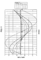
- FIG. 11 is a graph showing calculated results of combined waves of two sound waves.
- FIG. 12 is a sectional view showing a jet flow generating apparatus according to another embodiment.
- FIG. 13 is a perspective view showing a jet flow generating apparatus according to another embodiment.
- FIG. 14 is a schematic diagram showing wave forms in the case that, for example, two chambers described above are used and phases of the sound waves generated in the two chambers are shifted by 180°.
- FIG. 15 is a schematic diagram showing wave forms of the sound waves generated in three chambers.
- FIG. 16 is a table showing ratios of harmonics against a basic wave in the case that a speaker is driven with its rated input and 40% thereof.
- FIG. 17 is a sectional view showing a jet flow generating apparatus according to another embodiment, the sectional view taken along line B-B shown in FIG. 18 .
- FIG. 18 is a sectional view taken along line A-A shown in FIG. 17 .
- FIG. 19 is a schematic diagram showing a jet flow generating apparatus according to another embodiment.
- FIG. 20 is a table showing an example in the case that a signal of a vibration control unit is adjusted at a basic frequency of 100 (Hz) so that distortion components as harmonic components are decreased.
- FIG. 21 is a schematic diagram showing a jet flow generating apparatus according to another embodiment.
- FIG. 22 is a sectional view showing a jet flow generating apparatus according to another embodiment.
- FIG. 23 is a schematic diagram showing a sound wave in the case that one jet flow generating apparatus shown in FIG. 22 is used at a drive frequency of 200 (Hz).
- FIG. 24 is a schematic diagram showing a first combined wave form and a second combined wave form generated by two jet flow generating apparatuses shown in FIG. 22 and their combined wave form.
- FIG. 25 is a schematic diagram showing a noise spectrum.
- FIG. 26 is a sectional view showing a jet flow generating apparatus according to another embodiment of the present invention.
- FIG. 27 is a sectional view showing a jet flow generating apparatus according to a modification of the embodiment shown in FIG. 26 .
- FIG. 28 is a sectional view showing a jet flow generating apparatus according to another modification of the embodiment shown in FIG. 26 .
- FIG. 29 is a sectional view showing a jet flow generating apparatus according to another modification of the embodiment shown in FIG. 26 .
- FIG. 30 is a sectional view showing a jet flow generating apparatus according to another embodiment of the present invention.
- FIG. 31 is a sectional view showing a jet flow generating apparatus having one speaker.
- FIG. 32 is a schematic diagram showing a jet flow generating apparatus according to a modification of the embodiment shown in FIG. 30 .
- FIG. 33 is a schematic diagram showing a jet flow generating apparatus according to a modification of the embodiment shown in FIG. 32 .
- FIG. 34 is an enlarged sectional view showing an actuator according to a modification (No. 1).
- FIG. 35 is an enlarged sectional view showing an actuator according to another modification (No. 2).
- FIG. 36 is an enlarged sectional view showing an actuator according to another modification (No. 3).
- FIG. 37 is an enlarged sectional view showing an actuator according to another modification (No. 4).
- FIG. 38 is a schematic diagram showing a jet flow generating apparatus according to another modification of the embodiment shown in FIG. 32 .
- FIG. 39 is a schematic diagram showing a jet flow generating apparatus according to another modification of the embodiment shown in FIG. 28 .
- FIG. 40 is a perspective view showing a jet flow generating apparatus according to another embodiment of the present invention.
- FIG. 41 is a perspective view describing a practical usage of the jet flow generating apparatus shown in FIG. 40 .
- FIG. 42 is a perspective view showing a jet flow generating apparatus according to a modification of the embodiment shown in FIG. 40 .
- FIG. 43 is a sectional view showing a jet flow generating apparatus according to another embodiment.
- FIG. 44 is a perspective view showing a jet flow generating apparatus according to another modification of the embodiment shown in FIG. 40 .
- FIG. 45 is a sectional view showing nozzles shown in FIG. 44 .
- FIG. 46 is a sectional view showing nozzles of a jet flow generating apparatus according to a modification of the embodiment shown in FIGS. 44 and 45 .
- FIG. 47 is a schematic diagram showing an example of the usage of the jet flow generating apparatus having nozzles that are bent (No. 1).
- FIG. 48 is a schematic diagram showing an example of the usage of the jet flow generating apparatus having nozzles that are bent (No. 2).
- FIG. 49 is a sectional view showing a jet flow generating apparatus according to another embodiment.
- FIG. 50 is a sectional view showing a jet flow generating apparatus according to a modification of the embodiment shown in FIG. 49 .
- FIG. 51 is a sectional view showing a jet flow generating apparatus according to another modification of the embodiment shown in FIG. 49 .
- FIG. 52 is a sectional view showing a speaker type vibrating mechanism used in a jet flow generating apparatus according to another embodiment.
- FIG. 53 is a plan view showing a vibration plate, an edge member, and so forth shown in FIG. 52 .
- FIG. 54 is a sectional view showing a vibrating mechanism in which two vibrating mechanisms shown in FIG. 53 are symmetrically arranged.
- the present invention relates to a jet flow generating apparatus that generates a jet flow and cools a heat generating member such as an electronic part with the generated jet flow, an electronic device that is equipped with the jet flow generating apparatus, and a jet flow generating method.
- FIG. 1 is a perspective view showing a jet flow generating apparatus according to an embodiment of the present invention.
- FIG. 2 is a sectional view showing the jet flow generating apparatus.
- a jet flow generating apparatus 1 has, for example, two independent casings 11 and 12 .
- the casings 11 and 12 have vibrating mechanisms 5 and 6 , respectively.
- the vibrating mechanisms 5 and 6 have vibration plates 7 and 8 , respectively.
- the vibration plates 7 and 8 are composed of a soft film material, for example, PET (polyethylene terephthalate) film or the like.
- the vibrating mechanisms 5 and 6 each have a structure of, for example, a speaker.
- the vibrating mechanisms 5 and 6 each are composed of a coil, a magnet, and so forth (not shown).
- the vibration plates 7 and 8 are asymmetrical with respect to the directions of the vibrations thereof.
- the casings 11 and 12 form chambers 11 a and 12 a , respectively.
- the chambers 11 a and 12 a each are filled with a gas.
- As the gas for example, air can be used.
- a plurality of nozzles 13 and 14 are disposed as openings on side surfaces of the casings 11 and 12 , respectively.
- Each chamber may not have a plurality of nozzles 13 (or nozzles 14 ), but one nozzle 13 (or nozzle 14 ).
- the nozzles such as the nozzle 13 and so forth may not protrude from the casing 11 and so forth, respectively.
- the nozzles such as the nozzle 13 and so forth may be formed in the wall surfaces of the casing 11 and so forth.
- Hole portions 11 b and 11 b are formed at the upper portions of the casings 11 and 12 , respectively.
- the vibrating mechanisms 5 and 6 are disposed so that they cover the hole portions 11 b and 12 b , respectively.
- the vibrating mechanisms 5 and 6 are controlled by a control unit 10 .
- the control unit 10 has a power supply circuit 15 that applies a sinusoidal AC voltage to the vibrating mechanisms 5 and 6 , and a control circuit 16 that controls the wave forms of the vibrations of the vibrating mechanisms 5 and 6 .
- the control unit 10 causes the control circuit 16 to control the vibrating mechanisms 5 and 6 so that vibrations of air generated by the vibrating mechanisms 5 and 6 are offset or weakened.
- the casings 11 and 12 are made of a highly rigid material such as a metal, for example, aluminum.
- the casings 11 and 12 are formed in, for example, a rectangular parallelepiped shape.
- the shapes, materials, openings, and so forth of the casings 11 and 12 are the same.
- the shapes, materials, and so forth of the vibration plates 7 and 8 are the same.
- the control unit 10 drives the vibrating mechanisms 5 and 6 so as to sinusoidally vibrate them: As a result, the volumes of the chambers 11 a and 12 a increase or decrease. As the volumes of the vibration plates 7 and 8 vary, the internal pressures of the chambers 11 a and 12 a also vary. Consequently, air streams pulsatively generate through the nozzles 13 and 14 . When the vibration plate 7 deforms in the direction in which the volume of the chamber 11 a increases, the internal pressure of the chamber 11 a decreases. Thus, outer air of the casing 11 enters the chamber through the nozzles 13 .
- the vibrations of the vibration plates 7 and 8 are propagated as sound waves in air.
- the vibrations of the vibration plates 7 and 8 cause dense and thin portions of air to be formed from the chambers 11 a and 12 a to the outside.
- a sound wave as a longitudinal wave takes place.
- the sound wave becomes noise.
- the noise sounds are generated mainly from the nozzles 13 and 14 .
- the vibrations of the vibration plates 7 and 8 are controlled by the control unit 10 so that the vibrations of air generated by the casings 11 and 12 are offset or weakened each other. Specifically, the vibrations are controlled so that the wave forms of the vibrations of the vibration plates 7 and 8 become the same and the phases thereof become inverse. Thus, since the wave forms weaken each other, the noise of the apparatus can be decreased.
- FIG. 4 is a perspective view showing an example in which heat of, for example, an IC chip is radiated by the jet flow generating apparatus 1 .
- the IC chip 50 is disposed in contact with a heat spreader (or a heat transporting member having a heat pipe function).
- a plurality of heat radiation fins 52 is mounted on a heat spreader 51 .
- the jet flow generating apparatus 1 is disposed so that the air jet flows of the nozzles 13 and 14 face the heat radiation fins 52 .
- the heat generated by the IC chip 50 is spread by the heat spreader 51 and transferred to the heat radiation fins. Then, highly heated air remains in the vicinity of the heat radiation fins 52 . As a result, a thermal boundary layer is formed.
- the vibrating mechanisms 5 and 6 vibrate so as to discharge the jet flows generated by the nozzles 13 and 14 toward the heat radiation fins 52 . The jet flows break the thermal boundary layer. As a result, the heat is effectively radiated.
- the flow amount of a combined jet flow owing to the vibrations of the vibrating mechanisms such as the vibrating mechanism 5 and so forth can be increased.
- the clock frequencies of IC chips are increased, even if the calorific powers generated thereby are increased, the heat thereof can be effectively radiated.
- control unit 10 controls the phases of the vibrations of the sound waves so that the sound waves weaken each other. In other words, while the heat can be effectively radiated, the noise can be prevented from generating.
- the heat of a heat generating member can be effectively radiated in accordance with the length in the Y direction of the radiation fins such as the heat radiation fins 52 and so forth.
- the vibration plates are sinusoidally vibrated and the sound waves are offset, the sound waves can be more effectively offset than the case that the noise is weakened by two fans that discharge air. Since the sound wave that is output from one fan is generally noisy, it might be difficult to mute the noise with those two fans.
- the frequencies of the vibrating mechanisms 5 and 6 are around 100 (Hz), which is an audible range of human.
- FIG. 5 is a graph showing an audible characteristic of human.
- the graph is an equi-loudness curve (A characteristic) prescribed by JIS standard.
- the graph represents that in a frequency band from 20 (Hz) to 20 (kHz), when a human is exposed to the same sound pressure level, how he or she can hear it.
- the graph represents that with reference to a sound wave of 1 (kHz), at what intensity a human can hear sounds of individual frequencies.
- the graph shows that in the same sound pressure level, a human can hear a sound of 50 (Hz) weaker than a sound of 1 (kHz) by 30 (dB).
- the sound pressure level Lp (dB) is defined by the following formula (1).
- Lp 20 log( p/p 0) Formula (1)
- p represents the sound pressure (Pa)
- p0 represents a reference sound pressure (20 ⁇ Pa).
- FIG. 6 is a graph showing a result of the measurement of noise by the jet flow generating apparatus 1 using a sound pressure meter.
- the graph shows a result of the measurement of the sound waves in a frequency band from around 20 (Hz) to 20 (kHz), which is an audible range of human.
- the graph shows “sound pressure level” rather than “noise level”.
- the graph is not compensated with the foregoing A characteristic (the sound pressure level is not compensated in accordance with the audible characteristic of human). Consequently, the graph shown in FIG. 6 represents that as the frequency becomes lower, the sound pressure level becomes higher.
- the noise that humans can hear does not almost vary.
- the graph shows that the sound waves most effectively weaken each other at 100 (Hz).
- the sound waves generated by the nozzles such as the nozzle 13 and so forth do not strengthen each other with almost the maximum amplitude, the noise can be almost prevented from generating.
- the reason why the foregoing effect can be obtained will be described.
- the distance between the opening 13 of the chamber 11 a and the opening 14 of the chamber 12 a is denoted by d.
- the distance of AP is denoted by h.
- the distance of BP is denoted by i. If
- the triangle definition shows that the maximum limit of
- d needs to be smaller than the half wave length, namely d ⁇ /2.
- This phenomenon can be also understood with wave fronts of the sound waves generated by the two sound sources A and B as shown in FIG. 8 .
- a thick line represents a wave front of the sound source A
- a thin line represents a wave front of the sound source B.
- a solid line of the wave front represents a crest
- a broken line of the wave front represents a trough.
- the distance d between the sound sources A and B is d ⁇ /2 and the phases thereof are inverse.
- the two sound waves weaken each other at a plurality of points C (white circles) with the maximum amplitude. As a result, there are no positions that strengthen with the maximum amplitude.
- the shapes of the chambers and so forth are not restricted.
- the number of chambers is 2
- the control unit 10 may cause the wave forms of the sound waves generated in the chambers to have phase differences of 360°/n.
- the phase differences of three wave forms X, Y, and Z need to be shifted by 120° each.
- the combined wave is represented by a solid line W.
- the sound waves weaken each other.
- the distance between openings that are the most spaced apart is ⁇ / ⁇ 2(n ⁇ 1) ⁇ . Since the wave length is sufficiently larger than the distance, the combined wave forms of the sound waves generated in the chambers weaken each other regardless of the positions and directions thereof. In other words, since the maximum amplitudes of the sound waves generated by the openings of the chambers do no strengthen, the noise of the apparatus can be almost prevented from generating.
- the wave forms of the sound waves generated in the chambers A and B have an amplitude a and the same phase
- the amplitude of a sound wave generated in the chamber C is 2 ⁇ a
- the phase of the sound wave generated in the chamber C is shifted by 180° (from the phase of each of the sound waves generated in the chambers A and B).
- the crest portions and the trough portions of the wave forms of the sound waves generated in the chambers A, B, and C weaken each other.
- the combined wave form becomes flat. Consequently, the muting effect can be obtained.
- FIG. 11 is a graph showing combined waves of two sound waves with a parameter of a distance d ranging from ⁇ /180 to ⁇ /2 in the foregoing experiment using the jet flow generating apparatus 1 .
- the amplitude on the vertical axis represents a relative value of each parameter value.
- the resultant sound is weaker than the sound of one chamber having one vibration plate.
- FIG. 12 is a sectional view showing a jet flow generating apparatus according to another embodiment of the present invention.
- the jet flow generating apparatus according to this embodiment is denoted by reference numeral 21 .
- the jet flow generating apparatus 21 is enclosed with one casing 22 .
- the space in the casing 22 is partitioned by two chambers 22 a and 22 b .
- the shapes, volumes, and so forth of the chambers 22 a and 22 b are almost the same.
- the chambers 22 a and 22 b compose a chamber group.
- Openings 22 c and 22 d are formed in the partitioned chambers 22 a and 22 b , respectively.
- the opening 22 c (or 22 d ) may be one opening or a plurality of openings.
- the shapes, sizes, and so forth of the openings 22 c and 22 d are almost the same.
- the materials and so forth of the casing 22 , the vibration plate 27 , and so forth of the jet flow generating apparatus 21 may be the same as those of the jet flow generating apparatus shown in FIG. 1 .
- a vibrating mechanism 25 for example, a speaker may be used.
- a control unit 20 that controls the vibrating mechanism 25 includes a power supply circuit and so forth that apply a sinusoidal AC voltage.
- the control unit 20 drives the vibrating mechanism 25 so as to sinusoidally vibrate the vibration plate 27 .
- the internal pressures of the chambers 22 a and 22 b alternately increase and decrease.
- air streams generate through the openings 22 c and 22 d .
- the air streams alternately flow from the inside to the outside of the casing 22 and from the inside to the outside thereof. Since air is discharged to the outside of the casing 22 , the air can be discharged to, for example, a highly heated portion so as to cool it.
- the vibration of the vibration plate 27 propagate as sound waves in air through the openings 22 c and 22 d .
- the sound waves generated by the openings 22 c and 22 d are generated from the front surface and the rear surface of the same vibration plate. Since the shapes and so forth of the chambers 22 a and 22 b are the same as those of the openings 22 c and 22 d , the wave forms of the sound waves are the same and the phases thereof are inverted. Thus, since the sound waves generated through the openings 22 c and 22 d are offset, the noise of the apparatus is suppressed.
- the noise of the apparatus can be decreased.
- the jet flow generating apparatus 21 has, for example, three or more vibrating mechanisms as a modification of the embodiment shown in FIG. 12 , if the amplitudes and phases of the vibration plates are adjusted, the sound waves weaken each other.
- FIG. 13 is a perspective view showing a jet flow generating apparatus according to another embodiment of the present invention.
- the jet flow generating apparatus according to this embodiment is denoted by reference numeral 41 .
- the jet flow generating apparatus 41 has a plurality of nozzles 43 and a plurality of nozzles 44 that are alternately arranged at intervals of a distance d on the two casings 11 and 12 .
- the plurality of nozzles 43 and the plurality of nozzles 44 are one-dimensionally arranged.
- the same effect as the jet flow generating apparatuses according to the foregoing embodiments can be obtained.
- the heat radiating process can be effectively performed while the noise is prevented from generating.
- the casings such as the casing 11 and so forth may have a sound absorbing member and a lid member.
- the sound absorbing member for example, glass wool can be used.
- the noise of the apparatus can be further decreased.
- the shapes and materials of the chambers, the shapes of the openings, the shapes of the vibration plates, the shapes, materials, and so forth the vibration plates and the driving devices thereof are the same.
- the shapes and so forth of the chambers and vibration plates may be different from each other.
- the distance between adjacent openings formed in a chamber and the vibrations of the vibrating mechanisms are controlled.
- the wave forms can be adjusted depending on the shapes, materials, and structures of the chambers, and the shapes and so forth of the openings.
- the phases of the sound waves may be controlled.
- the amplitudes and frequencies of the sound waves may be controlled so as to cause a plurality of the sound waves to weaken each other.
- a speaker is exemplified.
- a vibrating mechanism using a piezoelectric device may be used.
- the jet flow generating apparatuses according to the foregoing embodiments do not always need to have a vibrating mechanism. Instead, a jet flow may be generated by the rotation of a rotor like a roots pump.
- FIG. 14 is a graph showing wave forms of the sound waves generated in two chambers and whose phases are shifted by 180°. As shown in the graph, since wave forms 31 and 32 as basic frequency components are shifted by 180°, they weaken each other. However, since wave forms 33 and 34 of harmonics of the wave forms 31 and 32 have the same phase, they strengthen each other. Vibrations having harmonic components any integer times higher than the second harmonic component, namely a fourth harmonic, a sixth harmonic, and so forth strengthen each other. Thus, the noise of the apparatus is increased.
- the amplitude of a third harmonic is sufficiently small. In reality, this characteristic can be considered as follows.
- first harmonics and third harmonics are offset.
- second harmonics strengthen each other.
- the noise level becomes 21 (dBA), which is twice higher than 18 (dBA) of second harmonics.
- the noise level does not satisfy the target.
- third harmonics strengthen each other, the sound waves of first harmonics and second harmonics are offset.
- the noise level becomes 19.8 (dBA), which is three times higher than 15 (dBA).
- This noise level satisfies the target.
- the phases of the sound waves generated in the three chambers are shifted by 120° each. As a result, the noise level can be more decreased than the target value.
- the target value of the noise level is 20 (dBA)
- the foregoing noise level 22.9 (dBA) which is a noise level of a sound wave generated in one chamber, may be designated as a target value.
- the speaker can be driven with a drive power that is sufficiently lower than the rated input thereof.
- the ratio of harmonics contained in the generated sound wave increases.
- FIG. 16 is a table showing the ratio of amplitudes of harmonics against a basic wave in the case that a speaker is driven with its rated input (0.5 (W)) and 40 (%) (0.2 (W)) of the rated input. This table shows that when the speaker is driven with 40 (%) (0.2 (W)) of the rated input, harmonic components are decreased.
- the embodiment since the offset effect of the sound waves can be obtained against distortion components, the embodiment can be applied to a vibrating mechanism that distorts.
- an inexpensive vibrating mechanism can be used because the specifications thereof are not restricted.
- the number of chambers for which noise is decreased can be minimized.
- the power consumption and space of the apparatus can be decreased.
- FIG. 17 and FIG. 18 are sectional views showing a jet flow generating apparatus according to another embodiment of the present invention.
- FIG. 18 is a sectional view taken along line A-A of FIG. 17 .
- FIG. 17 is a sectional view taken along line B-B of FIG. 18 .
- the jet flow generating apparatus according to this embodiment is denoted by reference numeral 61 .
- the jet flow generating apparatus 61 is enclosed in a casing 68 having chambers 62 a and 62 b .
- the chambers 62 a and 62 b are composed of the casing 68 and a wall 69 disposed therein.
- vibrating mechanisms 65 a and 65 b are disposed, respectively.
- the vibrating mechanisms 65 a and 65 b each have the same structure as the vibrating mechanisms such as the vibrating mechanism 5 and so forth shown in FIG. 2 .
- the casing 68 has nozzles 63 a and 63 b that pass through the inside of the chambers 62 a and 62 b , respectively. Air is discharged from the chambers 62 a and 62 b through the nozzles 63 a and 63 b , respectively.
- the vibrating mechanisms 65 a and 65 b are disposed so that they close opening portions 66 a and 66 b , respectively, formed in the wall 69 .
- the vibrating mechanism 65 b vibrates air in the chamber 62 a . As a result, air is discharged from the nozzle 63 a .
- the vibrating mechanism 65 a vibrates air in the chamber 62 b . As a result, air is discharged from the nozzle 63 b .
- the vibrating mechanisms 65 a and 65 b are connected to a control unit (not shown) that is the same as the control unit 10 shown in FIG. 2 .
- the control unit controls the vibrating mechanisms 65 a and 65 b so that the phases of the vibrations of the vibrating mechanisms 65 a and 65 b are inverted and the amplitudes of the vibrations thereof are the same.
- the vibrating mechanisms 65 a and 65 b are disposed so that their vibration directions R are the same and their orientations are opposite. Thus, even if the vibrating mechanisms 65 a and 65 b are vibrating mechanisms or vibration plates that are asymmetrical like speakers, they can secure overall symmetry. Thus, the vibrating mechanisms 65 a and 65 b allow the wave forms of the sound waves generated by the nozzles 63 a and 63 b to become the same as much as possible. As a result, the quietness of the apparatus can be improved.
- the material, size, shape, volume, and size or shape of opening portions (nozzles) of one chamber formed on the front side of the vibration plate should be the same as those of the other chamber formed on the rear side thereof.
- the sound waves generated in these chambers are inverted.
- a structure in which a first coil and a second coil are disposed on a first plane (for example, the front surface) of a proper flat member and a second plane (for example, the rear surface) thereof almost in parallel with the first plane, respectively, can be used.
- the first coil and the second coil for example, planar coils can be used.
- the flat member a soft resin or a rubber member can be used.
- a first magnet and a second magnet are disposed on the first plane and the second plane on which the first coil and the second coil are disposed, respectively.
- the vibrating member can be disposed, for example, at the center of the chamber shown in FIG. 12 .
- the first magnet and the second magnet can be disposed at the trough portion and the ceiling portion of the casing 22 .
- the planar coils may be disposed on one of the first plane and second plane of the flat member.
- FIG. 19 is a schematic diagram showing a jet flow generating apparatus according to another embodiment of the present invention.
- members, functions, and so forth similar to those shown in FIG. 1 and FIG. 2 will be briefly described or their description will be omitted.
- the jet flow generating apparatus is denoted by reference numeral 71 .
- the jet flow generating apparatus 71 has a vibration control unit 70 .
- the vibration control unit 70 controls a vibrating mechanism 5 .
- the vibration control unit 70 has drive signal sources 72 , 73 , and 74 that output drive signals having different frequencies to the vibrating mechanism 5 .
- the jet flow also has a vibration control unit 75 .
- the vibration control unit 75 controls a vibrating mechanism 6 .
- the vibration control unit 75 has drive signal sources 76 , 77 , and 78 that output drive signals having different frequencies to the vibrating mechanism 6 .
- the drive signal sources 72 and 76 generate signals having the same basic frequency.
- the drive signal sources 73 and 74 generate drive signals so that harmonic components of the vibrating mechanism 5 do not vibrate.
- the drive signals cause the vibrating mechanisms such as the vibrating mechanism 5 and so forth to generate harmonics whose phases are inversed and whose amplitudes and frequencies are the same.
- the drive signal sources 77 and 78 generate drive signals so that harmonic components of the vibrating mechanism 6 do not vibrate.
- the vibrations of the base frequency weaken each other.
- the drive signal sources such as the drive signal sources 73 and 77 generate drive signals so that the vibrating mechanisms 5 and 6 do not vibrate harmonic components. In other words, the sound waves of basic frequency components weaken each other.
- the harmonic components are not generated, the noise of the apparatus can be decreased.
- FIG. 19 the structure shown in FIG. 19 and the structure shown in FIG. 12 can be combined.
- a jet flow generating apparatus having one vibration plate, two chambers, and the vibration control unit 70 connected to one vibration plate shown in FIG. 19 allows the sound waves of basic frequency components to weaken each other and harmonic components not to be generated. Thus, the noise of the apparatus can be decreased.
- FIG. 20 shows an example in which a signal of the vibration control unit 70 is adjusted so as to decrease distortion components as harmonic components in the case that the basic frequency is 100 (Hz).
- signals of 200 (Hz) and 300 (Hz) are superimposed with a signal of a basic frequency of 100 (Hz).
- a second harmonic (200 (Hz)) and a third harmonic (300 (Hz)) are decreased.
- FIG. 21 is a schematic diagram showing a jet flow generating apparatus according to another embodiment of the present invention.
- the jet flow generating apparatus according to this embodiment is denoted by reference numeral 81 .
- the jet flow generating apparatus 81 has chambers 11 a and 12 a .
- microphones 82 and 83 that detect the states (amplitudes, phases, and so forth) of the sound waves generated by vibrating mechanisms 5 and 6 are disposed, respectively.
- the detected states are fed back as signals to a vibration control unit 80 .
- the vibration control unit 80 controls the vibrations of the vibrating mechanisms 5 and 6 so that the sound waves generated thereby weaken each other.
- the noise of the apparatus can be decreased. Since the microphones 82 and 83 are disposed in the chambers 11 a and 12 a , respectively, the microphones 82 and 83 can detect the sound waves of the respective chambers without interference of the sound waves of the other chambers. Thus, the vibrations of the vibrating mechanisms 5 and 6 can be accurately controlled.
- the jet flow generating apparatuses 1 , 21 , 41 , 61 , 71 , and 81 are used to discharge air to a heat generating member and cool it.
- the present invention is not limited to do that.
- the jet flow generating apparatuses 1 , 21 , 41 , 61 , 71 , and 81 can be used for means for supplying a fuel of a fuel cell.
- an oxygen (air) intake opening of the fuel cell is disposed so that the oxygen intake opening faces a nozzle (opening portion) of a chamber of the jet flow generating apparatus according to each of the foregoing embodiments.
- the jet air discharged from the jet flow generating apparatus is sucked as an oxygen fuel from the intake opening.
- the overall apparatus is more thinly structured than the case that a fuel is supplied with an axial flow fan, the same power generation efficiency as the case that the axial flow fan is used can be obtained.
- FIG. 22 is a sectional view showing a jet flow generating apparatus according to another embodiment of the present invention.
- the jet flow generating apparatus is denoted by reference numeral 91 .
- the jet flow generating apparatus 91 has two jet flow generating apparatuses shown in FIG. 12 . These jet flow generating apparatuses are denoted by reference numerals 121 and 221 .
- the jet flow generating apparatuses 121 and 221 are substantially the same. Controlling portions 120 and 220 control vibration plates 127 and 227 so that their vibrations have almost the same amplitude, the same frequency, and inverted phases.
- the vibration plate 127 of the vibrating mechanism 125 moves in the direction in which the inner pressure of a chamber 122 b increases (in the lower direction shown in the drawing)
- the vibration plate 227 of the vibrating mechanism 225 moves in the direction in which the inner pressure of a chamber 222 b decreases (in the upper direction shown in the drawing).
- the vibration plate 227 moves of the vibrating mechanism 225 in the direction in which the inner pressure of a chamber 222 a decreases (in the lower direction shown in the drawing).
- the speaker type vibrating mechanisms such as the vibrating mechanism 125 and so forth are asymmetrical with respect to the vibration direction of the vibration plate 127 .
- the voice coil portion and yoke portion are asymmetrical with respect to the vibration direction.
- the pressure difference of the chamber 122 b owning to the vibration of the vibration plate 127 is larger than the pressure difference of the chamber 122 a .
- Wave forms of the sound pressures generated by the openings 122 c , 122 d , 222 c , and 222 d are denoted by reference numerals 83 a , 83 b , 93 a , and 93 b , respectively.
- the amplitudes of these sound waves have the relation of wave form 83 b >wave form 83 a and wave form 93 b >wave form 93 a .
- a combined wave form 84 first combined wave form
- a combined wave form 94 second combined wave form
- the first combined wave form 84 weakened in the chambers 122 a and 122 b and the second combined wave form 94 weakened in the chambers 222 a and 222 b are combined and weakened. Thus, the noise of the apparatus can be further decreased.
- FIG. 23 and FIG. 24 show a result of an experiment about the embodiment.
- FIG. 23 shows a wave form of a sound pressure in the case that only the jet flow generating apparatus 121 of the jet flow generating apparatus 91 is used and that the drive frequency is 200 (Hz). In other words, FIG. 23 shows the first combined wave form.
- the vibrating mechanism 125 is asymmetrical, the sound wave is not perfectly flat.
- FIG. 24 shows the first combined wave form 84 , the second combined wave form 94 , and the final combined wave form 90 generated by the jet flow generating apparatuses 121 and 221 .
- the drive frequencies of these signals are 200 (Hz) and the phase difference is 170°.
- the combined wave forms weaken each other.
- the sound pressure of the final combined wave form is around 1 ⁇ 2 of that of each combined wave form.
- the present invention is not limited to the unit of the graph and scale values shown in FIG. 23 and FIG. 24 .
- FIG. 25 shows a noise spectrum of the experiment. As shown in the graph, it is clear that noise is decreased by around 20 (dB) at frequencies 200 (Hz) and 600 (Hz).
- the distance between two openings that are the most spaced apart satisfies the foregoing formula (2) or formula (4), there is no portion in which the first combined wave form and the second combined wave form strengthen each other.
- the distance between the opening 122 c of the chamber 122 a and the opening 222 d of the chamber 222 b needs to satisfy the foregoing formula (2) or formula (4).
- the structure of the jet flow generating apparatus 121 is the same as the structure of the jet flow generating apparatus 221 , their structures may be different. When the structures of the two apparatuses are different, the phases, amplitudes, and so forth need to be controlled so that the final combined wave form weakens.
- the jet flow generating apparatus 91 has two casings ( 121 and 221 ). Alternatively, the jet flow generating apparatus 91 may have three or more casings.
- the phase difference is 170°.
- the phase difference can be a value with which the noise levels of the combined wave forms decrease.
- the drive frequencies thereof can be controlled so as to decrease the noise.
- another sound wave generating means for example, a speaker (not shown), may be disposed.
- the noise level can be decreased.
- the noise level of the combined wave can be further decreased.
- the vibration plates such as the vibration plate 127 and so forth are driven with sine waves.
- the vibration plates such as the vibration plate 127 and so forth may be driven with signals of which the sound waves generated by the vibration plates such as the vibration plate 127 and so forth do not contain harmonic components.
- the noise decreasing effect is further improved. That means that the peak in the noise level at 400 (Hz) shown in FIG. 25 disappears.
- FIG. 26 is a sectional view showing a jet flow generating apparatus according to another embodiment of the present invention.
- the jet flow generating apparatus according to this embodiment is denoted by reference numeral 101 .
- the jet flow generating apparatus 101 has a casing 172 .
- the casing 172 has chambers 172 a and 172 b partitioned by a vibration plate 145 .
- An actuator 178 that vibrates the vibration plate 145 is disposed outside the casing 172 .
- a rod 185 of the actuator 178 is connected to the vibration plate 145 .
- the actuator 178 moves the vibration plate 145 .
- the rod 185 passes through a through-hole 172 e formed in the casing 172 .
- the actuator 178 has a yoke 182 , a magnet 183 , a coil 184 , and so forth.
- a control unit 170 applies for example, an AC voltage to the coil.
- the coil causes the rod 185 to move in the upper and lower directions shown in the drawing. Consequently, the vibration plate 145 vibrates.
- nozzles 173 and 174 alternately generate a jet flow.
- the nozzles 173 and 174 generate the sound wave having inverted phases. The sound waves weaken each other.
- the actuator 178 since the actuator 178 is disposed outside the casing 172 , the volumes of the chambers 172 a and 172 b can be almost the same. If the actuator 178 were disposed inside the casing 172 , heat of the actuator 178 would remain in the chamber 172 a or 172 b . If the vibration plate 145 were vibrated in this state, a heated air stream would be discharged. As a result, the heat radiation capacity would deteriorate.
- the disadvantage can be solved.
- FIG. 27 is a sectional view showing a jet flow generating apparatus according to a modification of the embodiment shown in FIG. 26 .
- members, functions, and so forth similar to those shown in FIG. 26 will be briefly described or their description will be omitted.
- the jet flow generating apparatus is denoted by reference numeral 111 .
- the jet flow generating apparatus 111 has an absorption member 192 that absorbs a lateral vibration of a rod 185 .
- the absorption member 192 is composed of, for example, a bellows member.
- the absorption member 192 may be composed of flexible resin or rubber.
- the absorption member 192 can suppress the lateral vibration of the rod 175 against the vibration of the vibration plate 145 . As a result, the vibration plate 145 can be stably vibrated. If the rod 185 laterally vibrated, a coil 184 would contact a yoke 182 and so forth. As a result, a rubbing sound would generate.
- the absorption member 192 seals a through-hole 172 c formed in the casing 172 so as to keep the casing 172 airtight.
- the absorption member 192 can prevent air from leaking from the casing 172 through the through-hole 172 e .
- the absorption member 192 also functions as a seal member.
- coolant can be effectively discharged from the chambers 172 a and 172 b.
- a viscous fluid seal member that seals the through-hole 172 e may be disposed.
- FIG. 28 is a sectional view showing a jet flow generating apparatus according to another modification of the embodiment shown in FIG. 26 .
- the jet flow generating apparatus according to this modification is denoted by reference numeral 121 .
- the jet flow generating apparatus 121 has a casing 172 .
- bearings 105 a and 105 b for a rod 108 are mounted on the casing 172 .
- the bearings such as the bearing 105 a and so forth are composed of, for example, linear ball bearings, fluid bearings, or the like.
- the rod 185 passes through a vibration plate 145 .
- the rod 185 passes through a through-hole 172 f formed in a chamber 172 b side opposite to a through-hole 172 e .
- the bearings 105 a and 105 b are disposed in the vicinity of the through-holes 172 e and 172 f , respectively.
- This structure using both the bearings 105 a and 105 b can more suppress the lateral vibration of the rod 185 than the structure using only the bearing 105 a .
- the rod 185 can be stably moved.
- the vibration plate 145 can be effectively vibrated.
- the rod 185 extends from one side to the other side of the casing 172 , the volumes, shapes, or the like of the chambers 172 a and 172 b can become the same.
- the noise of the apparatus can be further decreased.
- the solid bearing 105 a may be filled with a liquid.
- the casing 172 can be air-tightly sealed against a gap between the rod 185 and the bearing 105 a or bearing 105 b.
- FIG. 29 is a sectional view showing a jet flow generating apparatus according to another modification of the embodiment shown in FIG. 26 .
- the jet flow generating apparatus according to the modification is denoted by reference numeral 131 .
- the jet flow generating apparatus 131 has chambers 172 a and 172 b . In the chambers 172 a and 172 b , bearings 106 a and 106 b for a rod 185 are mounted.
- the jet flow generating apparatus 131 does not have a through-hole 172 f at the lower portion of the casing.
- the jet flow generating apparatus 131 can have the same operation and effect as the jet flow generating apparatus 121 .
- a seal member may be disposed in the through-holes such as the through-hole 172 e and so forth of the casing 172 through which the rod 185 passes.
- FIG. 30 is a sectional view showing a jet flow generating apparatus according to another embodiment of the present invention.
- the jet flow generating apparatus according to this embodiment is denoted by reference numeral 201 .
- the jet flow generating apparatus 201 has an upper casing 202 A and a lower casing 202 B.
- the upper casing 202 A forms the contours of chambers 204 a and 204 b .
- the lower casing 202 B forms the contours of chambers 206 a and 206 b .
- the casing 202 A and the casing 202 B have almost the same shape, size, and so forth.
- Nozzles 207 A, 208 A, 207 B, and 208 B protrude from the chambers 204 a , 204 b , 206 a , and 206 b , respectively, in the casings 202 A and 202 B.
- Speaker type vibration generating devices 205 A and 205 B are disposed in the upper casing 202 A and the lower casing 202 B, respectively.
- An actuator 203 that is a driving unit for both the vibration generating devices 205 A and 205 B is disposed between the upper casing 202 A and the lower casing 202 B.
- the actuator 203 is composed of a magnet 203 a , a yoke 203 b , a coil 203 c , and so forth.
- a control unit 210 that controls the vibrations of the vibration generating devices 205 A and 205 B is electrically connected to the coil 203 c.
- the vibration generating device 205 A has a frame 213 A and a vibration plate 211 A mounted thereon through an edge member 215 A.
- a frame 213 A is fitted to a through-hole 202 Aa formed at a lower portion of the upper casing 202 A.
- An air hole portion 213 Aa is formed in the frame 213 A.
- the edge member 215 A has flexibility or elasticity.
- the edge member 215 A is made of, for example, resin or rubber.
- a partition member 212 A is disposed in the upper casing 202 A.
- the partition member 212 A forms the chambers 204 a and 204 b .
- a hole 212 Aa is formed at the center of the partition member 212 A.
- the frame 213 A of the vibration generating device 205 A is mounted on the partition member 212 A through a vibration absorption member 214 A so that the frame 213 A covers the hole 212 Aa.
- the lower vibration generating device 205 B has almost the same structure as the upper vibration generating device 205 A. They differ in that the coil 203 c is mounted on a vibration plate 2111 B. Like the vibration generating device 205 A, the vibration generating device 205 B is disposed above the hole 212 Ba of the partition member 212 B so that the vibration generating device 205 B covers the hole 212 Ba.
- a rod 209 passes through a through-hole 203 ba of the yoke 203 b .
- the rod 209 passes through the through-holes 202 Aa and 202 Ba.
- the rod 209 is connected to the vibration plate 211 A and the vibration plate 211 B. This structure causes the two vibration plate 211 A and 211 B to integrally vibrate.
- the upper casing 202 A is formed so that the volume of the chamber 204 a is almost the same as the volume of the chamber 204 b . In reality, the upper casing 202 A is formed so that the height of the lower chamber 204 b is larger than that of the upper chamber 204 a by the volume of the vibration generating device 205 A.
- the lower casing 202 B has the same structure as the upper casing 202 A.
- the control unit 210 applies an AC voltage to the coil 203 c , the rod 209 moves in the upper and lower directions shown in the drawing. As a result, the vibration plates 211 and 211 B vibrates in the upper and lower directions. When the vibration plates 211 A and 211 B move in the upper direction shown in the drawing, the inner pressures of the chambers 204 a and 206 b increase. As a result, air is discharged from nozzles 208 A and 208 B. Since the phases of the sound waves (in particular, sound waves of basic frequency) generated by the nozzles 207 A and 208 A are inverted, the sound waves weaken each other. Likewise, since the phases of the sound waves (in particular, sound waves of basic frequency) generated by the nozzles 207 B and 208 B are inverted, the sound waves weaken each other.
- the phases of the sound waves in particular, sound waves of basic frequency
- the noise of the apparatus can be decreased.
- the discharge amount of air can be increased with a small electric power and the cooling efficiency can be improved.
- FIG. 30 shows a jet flow generating apparatus using a conventional speaker 235 .
- the speaker 235 has a frame 213 , a vibration plate 211 , an edge member 215 , and a dumper 236 .
- the edge member 215 and the dumper 236 are disposed between the frame 213 and the vibration plate 211 .
- the jet flow generating apparatus 201 does not need the dumper 236 .
- the dumper 236 is effective to prevent the apparatus from laterally vibrating, since the vibration plate becomes a resistance against the vibration of the vibration plate, it consumes an extra power. Thus, when the dumper 236 is not required, the vibration plates such as the vibration plate 211 A and so forth can be vibrated with a low power consumption. When the same power as the case that the dumper 236 is used is supplied, since the amplitude of the vibration plate can be increased, the cooling efficiency is improved.
- a power of 2 (W) was applied to the speaker 235 shown in FIG. 31 and the vibration generating devices such as the vibration generating device 205 A and so forth shown in FIG. 30 and their displacements were measured.
- the same magnets and same yokes having the same size as the magnets were used.
- the size of the vibration plate 211 A was the same as the size of the size of the vibration plate 211 B.
- the diameter and weight of each of the vibration plates 211 A and 211 B were around 70 (mm) and 300 (g), respectively.
- the amplitude of the vibration plate 211 A was 2.26 (mm), which was twice as large as the case that the structure shown in FIG. 31 was used with the same power.
- the structure shown in FIG. 30 has two vibration plates, the efficiency thereof is doubled.
- the jet flow generating apparatus 201 since the jet flow generating apparatus 201 has one actuator 203 , the apparatus can be miniaturized.
- FIG. 32 shows a jet flow generating apparatus according to a modification of the embodiment (jet flow generating apparatus 201 ) shown in FIG. 30 .
- the jet flow generating apparatus according to this modification is denoted by reference numeral 231 .
- members, functions, and so forth similar to those shown in FIG. 30 will be briefly described or their description will be omitted.
- a flat vibration plate 221 A is mounted on an upper casing 232 A of the jet flow generating apparatus 231 through an edge portion 215 A.
- a flat vibration plate 221 B is mounted on a lower casing 232 B through an edge member 215 B.
- a coil 203 c is mounted on a mounting member 226 .
- the mounting member 226 and a rod 229 are connected.
- the rod 229 is connected to the vibration plates 221 A and 221 B through through-holes 232 Aa and 232 Ba.
- the vibration plates 221 A and 221 B integrally vibrate.
- the noise of the apparatus can be further decreased.
- FIG. 33 shows a jet flow generating apparatus according to another modification against the modification (jet flow generating apparatus 201 ) shown in FIG. 32 .
- the jet flow generating apparatus according to this modification is denoted by reference numeral 241 .
- the jet flow generating apparatus 241 has four casings.
- a rod 229 is connected to a vibration plates 221 A and 221 B through through-holes 232 Aa and 232 Ba.
- the rod 239 passes through the vibration plates 221 A and 221 B.
- the rod 239 is connected to vibration plates 221 C and 221 D through through-holes 232 Ab, 232 Bb, 232 Ca, and 232 Da.
- the discharge amount of coolant can be further increased.
- the number of casings can be adjusted.
- the discharge amount of coolant can be increased in proportion with the number of casings, only one actuator 203 is required.
- the actuator 203 is disposed at the center of the casings 232 A, 232 B, 232 C, and 232 D, namely between the upper casings 232 A and 232 B, the symmetry of the apparatus is not deteriorated.
- the rod 229 may pass through the vibration plates 221 A and 221 B.
- the bearings of the rod that passes through the vibration plates 221 A and 221 B may be disposed at an upper portion of the upper casing 232 A and a lower portion of the lower casing 232 B. This structure applies to the jet flow generating apparatus 241 shown in FIG. 33 .
- FIG. 34 to FIG. 37 are enlarged sectional views showing actuators according to modifications of the actuator 203 of the jet flow generating apparatuses 201 , 231 , and 241 .
- a bearing 240 of a rod 209 is disposed in a through-hole 203 ba of a yoke 203 b .
- the bearing 240 is, for example, a ball bearing.
- the bearing 240 can prevent the rod 209 from laterally vibrating.
- the bearing may be a fluid bearing rather than the forgoing solid bearing.
- fluid is preferably liquid.
- Fluid is more preferably magnetic fluid.
- viscous liquid may be contained in the bearing 240 .
- the bearing 240 seals the inside of the upper casing 232 A against the inside of the lower casing 232 B. As a result, coolant can be effectively discharged from the upper casings 232 A and 232 B.
- a seal member 242 A is disposed between an upper casing 232 A and a rod 209
- a seal member 242 B is disposed between a lower casing 232 B and a rod 209
- the seal members 242 A and 242 B are made of, for example, rubber, resin, or the like.
- the seal members 242 A and 242 B can seal the inside the upper casing 232 A against the inside of the lower casing 232 B.
- coolant can be effectively discharged from the casing 232 A and 232 B.
- a through-hole 203 ba and so forth may be filled with a liquid seal member.
- FIG. 36 shows a combination of the structure shown in FIG. 34 and the structure shown in FIG. 35 .
- the structure shown in FIG. 36 can prevent the rod 209 from laterally vibrating.
- the structure shown in FIG. 36 can seal the inside of an upper casing 232 A against the inside of a lower casing 232 B.
- FIG. 37 shows a structure in which bearings 243 A and 243 B are fitted to through-holes 232 Aa and 232 Ba of an upper casing 232 A and a lower casing 232 B, respectively.
- the bearings 243 A and 243 B are solid bearings or fluid bearings.
- a rod 209 can be stably moved.
- FIG. 38 shows a jet flow generating apparatus according to another modification of the modification (the jet flow generating apparatus 231 ) shown in FIG. 32 .
- the jet flow generating apparatus according to this modification is denoted by reference numeral 251 .
- the jet flow generating apparatus 251 uses a driving mechanism in which an actuator 255 drives a piston 255 a with the pressure of fluid.
- the fluid is supplied from a fluid supply source 252 to the actuator 255 through a fluid pipe 254 or one of pipes 256 and 257 selected by a selection valve such as a solenoid valve or the like.
- the piston 255 a is secured to a rod 209 .
- This structure also allows vibration plates 221 A and 221 B to vibrate.
- the fluid may be any of solid and gas.
- FIG. 39 shows a jet flow generating apparatus according to another modification of the modification (jet flow generating apparatus 121 ) shown in FIG. 28 .
- the jet flow generating apparatus according to this modification is denoted by reference numeral 261 .
- the jet flow generating apparatus 261 has an actuator 265 .
- the actuator 265 uses a conventional rotational motor. The rotational motion of the motor is converted into a linear motion of a rod 185 by a link mechanism 266 . This structure also allows the vibration plate 145 to vibrate.
- FIG. 40 is a perspective view showing a jet flow generating apparatus according to another embodiment of the present invention.
- the jet flow generating apparatus is denoted by reference numeral 301 .
- the jet flow generating apparatus 301 has a casing 302 .
- the casing 302 forms the contours of chambers 302 a and 302 b .
- the casing 302 has one of the foregoing vibration plates.
- the vibration plate partitions the casing 302 and forms the chambers 302 a and 302 b .
- the casing 302 has short nozzles 303 a and long nozzles 303 b .
- the long nozzles 303 b are made of, for example, metal, resin, or the like.
- the long nozzles 303 b are bent. For example, six short nozzles 303 a and one long nozzle 303 b are disposed on each of the chambers 302 a and 302 b.
- the short nozzles 303 a disposed on the upper and lower chambers 302 a and 302 b have the same length.
- the long nozzles 303 b disposed on the upper and lower chambers 302 a and 302 b have the same length. This is because the phases of the sound waves generated by the upper nozzles disposed on the upper chamber 302 a and the phases of the sound waves generated by the lower nozzles disposed on the lower chamber 302 b are inversed so that the sound waves weaken each other.
- FIG. 41 is a perspective view describing a practical usage of the jet flow generating apparatus 301 shown in FIG. 40 .
- a circuit board 246 has a CPU 248 .
- a heat sink 247 is contacted to the CPU 248 .
- the heat sink 247 diffuses heat of the CPU 248 .
- a plurality of IC chips 249 are mounted in the vicinity of the CPU 248 on the circuit board 246 .
- two jet flow generating apparatuses 301 are stacked.
- the jet flow generating apparatuses 301 are arranged so that coolant discharged from the short nozzles 303 a are discharged to heat radiation fins 247 a of the heat sink 247 and that coolant discharged from the long nozzles 303 b are discharged to the IC chips 249 . Since the jet flow generating apparatuses 301 are arranged in the foregoing manner, they can directly cool the IC chips 249 .
- the jet flow generating apparatus 301 is not limited to the foregoing embodiment.
- the number of long nozzles 303 b and the number of short nozzles 303 a are not limited to those of the foregoing embodiment.
- the long nozzles 303 b can be made of, for example, a flexible material.
- the long nozzles 303 b can be made of rubber, flexible resin, bellows, or the like.
- the directions of the nozzles can be changed in accordance with the arrangement of various heat generating members.
- FIG. 42 shows a jet flow generating apparatus according to a modification of the embodiment (jet flow generating apparatus 301 ) shown in FIG. 40 .
- FIG. 42 to FIG. 46 members, functions, and so forth similar to those shown in FIG. 40 will be briefly described or their description will be omitted.
- the jet flow generating apparatus is denoted by reference numeral 311 .
- long nozzles 304 b are thicker than the foregoing long nozzles 303 b .
- the cross section of flow path which is perpendicular to the flow direction of coolant is larger than the cross section of each of the longer nozzle 303 b .
- a nozzle 305 is disposed on the discharge opening side of each of the long nozzles 304 b .
- the nozzles 305 can be omitted.
- each of the long nozzles 304 b is larger than the flow path of each of the short nozzles 304 a , the resistance of the former is larger than that of the latter by the difference between the lengths.
- the resistance of the flow path of each of the long nozzles 304 b can be prevented from increasing.
- coolant can be discharged from the long nozzles 304 b with a proper flow amount and a proper flow rate.
- FIG. 43 shows a jet flow generating apparatus according to another embodiment.
- the jet flow generating apparatus according to this embodiment is denoted by reference numeral 321 .
- Nozzles 304 of the jet flow generating apparatus 321 inwardly protrude from a side wall 302 c of a casing 302 .
- the thickness and length of each of the nozzles 304 , the volume of each of chambers such as a chamber 302 a and so forth, the performance of an actuator (not shown), and the amplitude, frequency, and so forth of a vibration plate 306 are parameters of the flow rate of coolant discharged from each of the nozzle 304 .
- each of the nozzles 304 When coolant is discharged at a desired flow rate and at a desired frequency, they are affected by the length of each of the nozzles 304 .
- each of the nozzles may be adjusted to a predetermined length.
- the length of each of the nozzles may not be freely adjusted due to the restriction of the arrangement of the jet flow generating apparatus 321 and the restriction of the position of a heat sink (not shown).
- the nozzles 304 are partly protruded in the chambers 302 a and 302 b , the lengths of the nozzles 304 can be adjusted for the desired values.
- the lengths of the nozzles 304 can be increased as much as possible.
- the frequency of the generated sound can be lowered.
- the generated sound can be weakened as much as possible.
- FIG. 44 shows a jet flow generating apparatus according to another modification of the embodiment (jet flow generating apparatus 301 ) shown in FIG. 40 .
- the jet flow generating apparatus according to this modification is denoted by reference numeral 331 .
- All nozzles 307 a and 307 b of the jet flow generating apparatus 331 are bent so that coolant is discharged to heat radiation fins 247 a of a heat sink 247 disposed at a lower portion of the jet flow generating apparatus 331 .
- FIG. 45 is a sectional view taken from the direction in which the heat radiation fins 247 a are disposed, namely, the nozzles 307 a and 307 b are cut in the vertical direction of the drawing. Tips of the nozzles 307 a protruding from the upper chamber 302 a are arranged at positions lower than tips of the nozzles 307 b against the position of the heat radiation fins 247 a.
- the jet flow generating apparatus and the heat sink are simply arranged as shown in FIG. 41 , their installation area becomes large. In contrast, according to the embodiment, the installation area can be decreased as much as possible.
- a heat insulator or the like can be interposed between the heat sink 247 and the jet flow generating apparatus 331 .
- FIG. 46 shows a jet flow generating apparatus according to another modification of the modification (jet flow generating apparatus 331 ) shown in FIG. 44 and FIG. 45 .
- the jet flow generating apparatus according to this modification is denoted by reference numeral 341 .
- nozzles 308 a and nozzles 308 b are arranged in a zigzag pattern.
- the nozzles 308 a and 308 b are alternately arranged on the chambers 302 a and 302 b (in the vertical direction in the drawing).
- the arrangement can contribute to the improvement of the muting effect.
- FIG. 47 and FIG. 48 show an example of the usage of the jet flow generating apparatus having the foregoing bent nozzles.
- the heat sink 247 is disposed outside a case 270 of a computer.
- the jet flow generating apparatus 351 is disposed in the case 270 so that nozzles 309 protrude toward the heat sink 247 .
- coolant discharged to a heat sink should be at a low temperature.
- the outer temperature of the case 270 is the lowest.
- the inner temperature of the case 270 is higher than the outside of the case 270 because of heat generated by inner parts of the case 270 .
- to cool a CPU disposed in a desktop PC or the like air in the case is discharged to the CPU.
- a heat radiation device that has high efficiency is desired.
- it is preferred to dispose the heat sink and the jet flow generating apparatus outside the case if there is a need to neatly package them because of limited space or desired design, structures shown in FIG. 47 and FIG. 48 can be considered.
- FIG. 49 is a sectional view showing a jet flow generating apparatus according to another embodiment.
- the jet flow generating apparatus according to this embodiment is denoted by reference numeral 361 .
- the jet flow generating apparatus 361 has a casing 362 .
- a vibration plate 365 is disposed in the casing 362 .
- the vibration plate 365 has a cylindrical side wall 365 a .
- the side wall 365 a of the vibration plate 365 is formed in the vibration direction R of the vibration plate 365 .
- An upper edge portion and a lower edge portion formed on the side wall 365 a are supported by edge members 364 a and 364 b , respectively.
- the edge members 364 a and 364 b are mounted on the casing 362 .
- the edge members such as the edge member 364 a and so forth as supporting members have bendability or elasticity.
- the edge members are made of, for example, bellows shape resin or rubber.
- the side wall 365 a may be formed successively or intermittently in the peripheral direction.
- the casing 362 , the vibration plate 365 , and the edge member 364 a compose a chamber 362 a .
- the casing 362 , the vibration plate 365 , and the edge member 364 b compose a chamber 362 b .
- the chambers 362 a and 362 b are structured so that the volume of the chamber 362 a is almost the same as the volume of the chamber 362 b .
- the chamber 362 a has a plurality of openings 363 a denoted by dotted circles.
- the chamber 362 b has a plurality of openings 363 b .
- the openings 363 a and 363 b may be formed in a nozzle shape as described in each of the foregoing embodiments.
- An actuator 370 is disposed in the chamber 362 a .
- the actuator 370 vibrates the vibration plate 365 .
- the actuator 370 is composed of a yoke 376 , a magnet 372 , a plate 373 , a coil 378 , a movable member 374 , and so forth.
- the plate 373 has a function of a yoke.
- the coil 378 is wound on the movable member 374 .
- the vibration plate 373 is secured to the movable member 374 .
- a control unit 310 is electrically connected to the coil 378 .
- the control unit 310 generates a drive signal for the actuator 370 .
- Air holes 374 a are formed on the side surfaces of the movable member 374 .
- the vibration plate 365 can stably vibrate, but not laterally vibrate. Since the vibration plate 365 suppresses lateral vibration, the magnet 372 , the plate 373 , and so forth are prevented from colliding with the movable member 374 . Thus, the space between the plate 373 and so forth and the movable member 374 can be narrowed. As a result, the magnetic field applied to the coil 378 can be strengthen. Consequently, the driving mechanism can effectively obtain drive force. In addition, since the members of the actuator 370 are prevented from colliding with each other, higher mode vibrations can be suppressed. As a result, the noise of the apparatus can be decreased.
- the distance between the edge member 364 a and the edge member 364 b becomes larger and the vibration plate 365 more stably vibrates.
- the size of the casing 362 is not changed, if the distance between the edge member 364 a and the edge member 364 b is largely increased, the volumes of the chambers 362 a and 362 b are decreased. Thus, the distance between the edge member 364 a and the edge member 364 b needs to be properly adjusted.
- FIG. 50 is a sectional view showing a jet flow generating apparatus according to a modification of the embodiment (jet flow generating apparatus 361 ) shown in FIG. 49 .
- FIG. 50 to FIG. 52 members, functions, and so forth similar to those shown in FIG. 49 will be briefly described or their description will be omitted.
- the jet flow generating apparatus is denoted by reference numeral 371 .
- the jet flow generating apparatus 371 shown in FIG. 50 has a vibration plate 375 whose cross section has an almost a shape of a character H.
- the jet flow generating apparatus 371 also has chambers 362 a and 362 b .
- actuators 370 a and 370 b are disposed in the chambers 362 a and 362 b .
- the actuators 370 a and 370 b are similar to the actuator shown in FIG. 49 .
- the shape and volume of the chamber 362 a are the same as those of the chamber 362 b . Thus, this structure contributes to the reduction of the noise.
- FIG. 51 is a sectional view showing a jet flow generating apparatus according to another modification of the embodiment (jet flow generating apparatus 361 ) shown in FIG. 49 .
- the jet flow generating apparatus according to this modification is denoted by reference numeral 381 .
- the jet flow generating apparatus 381 has a casing 382 .
- a vibrating mechanism 388 is disposed in the casing 382 .
- the vibrating mechanism 388 has a frame 386 , actuators 370 a and 370 b , and a vibration plate 385 .
- the actuators 370 a and 370 b are supported by the frame 386 .
- a side wall 385 a of the vibration plate 385 is slidably supported by the frame 386 .
- the vibration plate 385 is vibrated by the actuators 370 a and 370 b .
- the side wall 385 a of the vibration plate 385 is slidable to the frame 386 in the vibration direction of the vibration plate 385 .
- the vibrating mechanism 388 according to the embodiment has the vibration plate 385 formed in a piston shape and the frame 386 as a cylinder.
- the periphery of the frame 386 of the vibrating mechanism 388 is mounted on a partition member 379 .
- chambers 382 a and 382 b are formed. Air holes 386 a and 386 b are formed in the frame 386 .
- the vibration plate 385 can stably vibrate, not laterally vibrate.
- a bearing (not shown) may be interposed between the frame 386 and the side wall 385 a .
- lubricant may be interposed between them.
- Lubricant of mineral oil type, synthetic type, or the like can be used.
- solid type lubricant of molybdenous type may be used.
- FIG. 52 is a sectional view showing a speaker type vibrating mechanism used in the foregoing jet flow generating apparatuses according to another embodiment of the present invention.
- the vibrating mechanism according to this embodiment is denoted by reference numeral 280 .
- the vibrating mechanism has an actuator 370 .
- the actuator 370 is composed of a yoke 376 , a magnet 372 , a plate 373 , a coil 378 , a movable member 347 , and so forth.
- the plate 373 has a function of a yoke.
- the coil 378 is wound around the movable member 374 .
- a vibration plate 285 is secured to the movable member 374 .
- the structure of the actuator 370 is the same as that of the actuator 370 shown in FIG. 49 and so forth.
- the yoke 370 of the actuator 370 is mounted on a frame 286 having air holes 286 a .
- the vibration plate 285 is also mounted on an
- FIG. 53 is a plan view showing the vibration plate 285 , the edge portion 287 , and so forth shown in FIG. 52 .
- a lead wire 284 through which a control signal is supplied from a control unit (not shown) to the coil 378 is wired along thread-shaped grooves 287 a formed on the edge member 287 .
- the lead wire 284 is connected to a terminal board 288 secured to the frame 286 .
- a portion denoted by reference numeral 287 b is a ridge line of the edge member 287 . Since the lead wire 284 is wired along the thread-shaped grooves 287 a , the stress applied to the lead wire can be decreased. As a result, the lead wire can be prevented from breaking.
- a lead wire (referred to as tinsel wire) is suspended and connected directly to a terminal board from a solenoid coil.
- tinsel wire since the vibration plate is movable and the terminal board is secured, one side of the tinsel wire is movable, whereas the other side is secured. Since the tinsel wire is repeatedly stressed by the vibrations at frequencies of several 10 (Hz) to several 100 (Hz) of the vibration plate, the durability of the speaker depends on the service life of the tinsel wire.
- the jet flow generating apparatus since the area of the vibration plate is proportionally decreased, the amplitude of the vibration plate should be increased so as to increase the discharge amount of coolant.
- the tinsel wire since the tinsel wire becomes short and the amplitude of the vibration plate becomes large, the stress applied to the tinsel wire tends to become large. In other words, the durability of the apparatus tends to deteriorate.
- a lead wire 289 is wired as denoted by a dashed line shown in FIG. 53 (when the lead wire 289 is wired from the center of the vibration plate 285 along the outer periphery), the stress applied to the lead wire 284 is large.
- the tinsel wire 284 when the tinsel wire 284 is spirally wired to the edge member 287 , the tinsel wire 284 can be effectively prevented from breaking.
- FIG. 54 is a sectional view showing a vibrating mechanism in which two vibrating mechanisms 280 shown in FIG. 53 are symmetrically disposed.
- the vibrating mechanism shown in FIG. 54 is denoted by reference numeral 290 .
- lead wires 284 are wired in spiral grooves formed on the front and rear surfaces of an edge member 287 . Using the bellows shape of the edge member 287 , the lead wires 284 can be spirally wired on the frond and rear surfaces of the edge member 287 .
- the vibrating mechanism 290 having the foregoing structure is disposed in a casing 382 shown in FIG. 51 instead of the vibrating mechanism 388 .
- a jet flow generating apparatus is structured.
- the foregoing tinsel wire may be buried in the edge member 287 .
- the shape of the tinsel wire can be kept for a long time, it can be suspended in a spiral coil shape, not secured to the edge member 287 and so forth. In this case, the spiral grooves of the edge member are not required. As a result, the stress applied to the lead wire can be decreased.
Applications Claiming Priority (6)
| Application Number | Priority Date | Filing Date | Title |
|---|---|---|---|
| JP2003374922 | 2003-11-04 | ||
| JPP2003-374922 | 2003-11-04 | ||
| JPP2004-035815 | 2004-02-12 | ||
| JP2004035815 | 2004-02-12 | ||
| JPP2004-232581 | 2004-08-09 | ||
| JP2004232581A JP4677744B2 (ja) | 2003-11-04 | 2004-08-09 | 噴流発生装置、電子機器及び噴流発生方法 |
Publications (2)
| Publication Number | Publication Date |
|---|---|
| US20050121171A1 US20050121171A1 (en) | 2005-06-09 |
| US8033324B2 true US8033324B2 (en) | 2011-10-11 |
Family
ID=34437604
Family Applications (1)
| Application Number | Title | Priority Date | Filing Date |
|---|---|---|---|
| US10/982,283 Expired - Fee Related US8033324B2 (en) | 2003-11-04 | 2004-11-03 | Jet flow generating apparatus, electronic apparatus, and jet flow generating method |
Country Status (6)
| Country | Link |
|---|---|
| US (1) | US8033324B2 (ja) |
| EP (1) | EP1529963B1 (ja) |
| JP (1) | JP4677744B2 (ja) |
| KR (1) | KR101120465B1 (ja) |
| CN (1) | CN100477898C (ja) |
| TW (1) | TWI250840B (ja) |
Cited By (15)
| Publication number | Priority date | Publication date | Assignee | Title |
|---|---|---|---|---|
| US20110114287A1 (en) * | 2009-11-19 | 2011-05-19 | General Electric Company | Chassis with distributed jet cooling |
| US20120285667A1 (en) * | 2011-05-13 | 2012-11-15 | Lighting Science Group Corporation | Sound baffling cooling system for led thermal management and associated methods |
| US20130213618A1 (en) * | 2008-10-30 | 2013-08-22 | General Electric Company | Synthetic jet embedded heat sink |
| US20130240182A1 (en) * | 2012-03-16 | 2013-09-19 | Inventec Corporation | Electronic device |
| US20150077934A1 (en) * | 2012-07-31 | 2015-03-19 | General Electric Company | Systems and methods for dissipating heat in an enclosure |
| US20150101886A1 (en) * | 2013-10-16 | 2015-04-16 | The Boeing Company | Synthetic jet muffler |
| US9425383B2 (en) | 2007-06-29 | 2016-08-23 | Parker-Hannifin Corporation | Method of manufacturing electroactive polymer transducers for sensory feedback applications |
| US9553254B2 (en) | 2011-03-01 | 2017-01-24 | Parker-Hannifin Corporation | Automated manufacturing processes for producing deformable polymer devices and films |
| US9590193B2 (en) | 2012-10-24 | 2017-03-07 | Parker-Hannifin Corporation | Polymer diode |
| US9761790B2 (en) | 2012-06-18 | 2017-09-12 | Parker-Hannifin Corporation | Stretch frame for stretching process |
| US9876160B2 (en) | 2012-03-21 | 2018-01-23 | Parker-Hannifin Corporation | Roll-to-roll manufacturing processes for producing self-healing electroactive polymer devices |
| US20180061737A1 (en) * | 2015-12-09 | 2018-03-01 | Ozyegin Universitesi | Heat sink cooling with preferred synthetic jet cooling devices |
| US10502246B2 (en) * | 2016-04-25 | 2019-12-10 | Rensselaer Polytechnic Institute | Methods and apparatus for controlling flow fields |
| US20200400136A1 (en) * | 2019-06-21 | 2020-12-24 | Clean Energy Labs, Llc | Venturi Pump Systems And Methods To Use Same |
| US11076249B2 (en) | 2018-11-07 | 2021-07-27 | Samsung Electronics Co., Ltd. | Electronic device and control method thereof |
Families Citing this family (56)
| Publication number | Priority date | Publication date | Assignee | Title |
|---|---|---|---|---|
| JP4298746B2 (ja) * | 2003-02-20 | 2009-07-22 | コーニンクレッカ フィリップス エレクトロニクス エヌ ヴィ | マイクロ・ジェットを備える冷却アセンブリ |
| JP4572548B2 (ja) * | 2004-03-18 | 2010-11-04 | ソニー株式会社 | 気体噴出装置 |
| US20060196638A1 (en) * | 2004-07-07 | 2006-09-07 | Georgia Tech Research Corporation | System and method for thermal management using distributed synthetic jet actuators |
| JP5088526B2 (ja) * | 2005-04-18 | 2012-12-05 | ソニー株式会社 | 噴流発生装置及び電子機器 |
| JP2006310586A (ja) | 2005-04-28 | 2006-11-09 | Sony Corp | 気流発生装置及び電子機器 |
| US20070023169A1 (en) * | 2005-07-29 | 2007-02-01 | Innovative Fluidics, Inc. | Synthetic jet ejector for augmentation of pumped liquid loop cooling and enhancement of pool and flow boiling |
| US8069910B2 (en) * | 2005-10-12 | 2011-12-06 | Nuventix, Inc. | Acoustic resonator for synthetic jet generation for thermal management |
| CN101297121B (zh) * | 2005-10-28 | 2011-02-02 | 三洋电机株式会社 | 流体输送装置、利用其的燃料电池及电子设备 |
| US7607470B2 (en) * | 2005-11-14 | 2009-10-27 | Nuventix, Inc. | Synthetic jet heat pipe thermal management system |
| JP4867324B2 (ja) * | 2005-12-12 | 2012-02-01 | ソニー株式会社 | 放熱装置及び電子機器 |
| JP4844236B2 (ja) * | 2005-12-20 | 2011-12-28 | ソニー株式会社 | ノズル、噴流発生装置、冷却装置及び電子機器 |
| JP5003018B2 (ja) * | 2006-03-01 | 2012-08-15 | ソニー株式会社 | 噴流発生装置 |
| JP5133970B2 (ja) * | 2006-03-21 | 2013-01-30 | コーニンクレッカ フィリップス エレクトロニクス エヌ ヴィ | 冷却装置、及びこのような冷却装置を有する電子装置 |
| US7787248B2 (en) * | 2006-06-26 | 2010-08-31 | International Business Machines Corporation | Multi-fluid cooling system, cooled electronics module, and methods of fabrication thereof |
| US7841385B2 (en) * | 2006-06-26 | 2010-11-30 | International Business Machines Corporation | Dual-chamber fluid pump for a multi-fluid electronics cooling system and method |
| JP2008008230A (ja) * | 2006-06-30 | 2008-01-17 | Sony Corp | 噴流発生装置、ノズル体及び電子機器 |
| EP2082137A1 (en) * | 2006-11-03 | 2009-07-29 | Koninklijke Philips Electronics N.V. | Active control of an acoustic cooling system |
| CN101542724A (zh) * | 2006-11-30 | 2009-09-23 | 皇家飞利浦电子股份有限公司 | 脉动冷却系统 |
| US20080137289A1 (en) * | 2006-12-08 | 2008-06-12 | General Electric Company | Thermal management system for embedded environment and method for making same |
| JP5320298B2 (ja) * | 2006-12-15 | 2013-10-23 | コーニンクレッカ フィリップス エヌ ヴェ | 周波数制御を有する脈動流体冷却 |
| JP2008280917A (ja) | 2007-05-10 | 2008-11-20 | Alps Electric Co Ltd | 圧電式気体噴射装置 |
| CN101680623B (zh) * | 2007-06-14 | 2014-09-24 | 皇家飞利浦电子股份有限公司 | 具有脉动流体冷却的光照装置 |
| US20090084866A1 (en) * | 2007-10-01 | 2009-04-02 | Nuventix Inc. | Vibration balanced synthetic jet ejector |
| JP5643651B2 (ja) * | 2007-12-07 | 2014-12-17 | コーニンクレッカ フィリップス エヌ ヴェ | 低ノイズ冷却装置 |
| EP2101351B1 (de) | 2008-03-13 | 2016-08-17 | Siemens Aktiengesellschaft | Kühlvorrichtung zur Kühlung eines Bauteils |
| US7990705B2 (en) * | 2008-05-09 | 2011-08-02 | General Electric Company | Systems and methods for synthetic jet enhanced natural cooling |
| KR20110069055A (ko) * | 2008-09-12 | 2011-06-22 | 코닌클리케 필립스 일렉트로닉스 엔.브이. | 갭형 공간 및 이에 결합된 인조 제트 발생기를 구비한 디바이스 |
| US20110240260A1 (en) * | 2008-10-17 | 2011-10-06 | Koninklijke Philips Electronics N.V. | Cooling arrangement |
| US8496049B2 (en) * | 2009-04-09 | 2013-07-30 | General Electric Company | Heat sinks with distributed and integrated jet cooling |
| US10274263B2 (en) * | 2009-04-09 | 2019-04-30 | General Electric Company | Method and apparatus for improved cooling of a heat sink using a synthetic jet |
| US9615482B2 (en) | 2009-12-11 | 2017-04-04 | General Electric Company | Shaped heat sinks to optimize flow |
| US8584735B2 (en) * | 2009-07-28 | 2013-11-19 | Aerojet Rocketdyne Of De, Inc. | Cooling device and method with synthetic jet actuator |
| US8490419B2 (en) * | 2009-08-20 | 2013-07-23 | United States Thermoelectric Consortium | Interlocked jets cooling method and apparatus |
| JP5868015B2 (ja) * | 2010-04-14 | 2016-02-24 | ゼネラル・エレクトリック・カンパニイ | 分散型ジェット冷却を備えたシャーシ |
| GB201101870D0 (en) | 2011-02-03 | 2011-03-23 | The Technology Partnership Plc | Pump |
| WO2013021547A1 (ja) * | 2011-08-05 | 2013-02-14 | パナソニック株式会社 | 燃料電池システム |
| US20130243030A1 (en) * | 2012-03-16 | 2013-09-19 | Nuventix, Inc. | Augmentation of Fans With Synthetic Jet Ejectors |
| EP2849949A4 (en) | 2012-05-15 | 2017-07-26 | Eyenovia, Inc. | Ejector devices, methods, drivers, and circuits therefor |
| US20140002991A1 (en) * | 2012-06-29 | 2014-01-02 | General Electric Company | Thermal management in optical and electronic devices |
| US9215520B2 (en) * | 2012-08-15 | 2015-12-15 | General Electric Company | Multi-function synthetic jet and method of manufacturing same |
| EP2971794A2 (en) * | 2013-03-15 | 2016-01-20 | Covestro Deutschland AG | Electroactive polymer actuated air flow thermal management module |
| US20140376185A1 (en) * | 2013-06-19 | 2014-12-25 | Fairchild Korea Semiconductor Ltd. | Cooling device |
| US20150041104A1 (en) * | 2013-08-09 | 2015-02-12 | Ge Aviation Systems, Llc | Systems and methods for robust and modular synthetic jet cooling |
| US9951767B2 (en) | 2014-05-22 | 2018-04-24 | General Electric Company | Vibrational fluid mover active controller |
| US10085363B2 (en) * | 2014-05-22 | 2018-09-25 | General Electric Company | Integrated compact impingement on extended heat surface |
| KR101651018B1 (ko) * | 2014-12-08 | 2016-08-24 | 엘지전자 주식회사 | 전자기 구동 기체 분출 장치 |
| CN105491854B (zh) * | 2015-12-29 | 2018-02-06 | 东南大学 | 一种多方向出口射流散热器 |
| CN107148193B (zh) * | 2016-09-29 | 2019-07-09 | 宁波三星医疗电气股份有限公司 | 一种充电桩及充电桩散热控制方法 |
| CN107559270B (zh) * | 2017-09-08 | 2023-11-14 | 浙江大学 | 合成射流平板湍流减阻装置 |
| TWI650284B (zh) * | 2017-09-30 | 2019-02-11 | Microjet Technology Co., Ltd | 流體裝置之控制方法 |
| DE102018100279B3 (de) | 2018-01-08 | 2019-04-18 | Beuth Hochschule Für Technik Berlin | Lüftervorrichtung zum Wärmeabtransport von einem Gegenstand und Gegenstand |
| US10827273B2 (en) | 2018-11-27 | 2020-11-03 | Apple Inc. | Dual loudspeaker enabled cooling |
| CN110162157A (zh) * | 2019-03-29 | 2019-08-23 | 联想(北京)有限公司 | 散热系统 |
| CN113597192B (zh) * | 2020-04-30 | 2024-02-02 | 维沃移动通信有限公司 | 一种电子设备 |
| CN115023097B (zh) * | 2021-09-30 | 2023-04-07 | 荣耀终端有限公司 | 射流发生装置及方法、散热器以及电子设备 |
| CN117222209B (zh) * | 2023-11-09 | 2024-02-20 | 东莞市富其扬电子科技有限公司 | 一种液冷散热器 |
Citations (28)
| Publication number | Priority date | Publication date | Assignee | Title |
|---|---|---|---|---|
| US3029743A (en) * | 1960-04-14 | 1962-04-17 | Curtiss Wright Corp | Ceramic diaphragm pump |
| US4109108A (en) * | 1976-10-01 | 1978-08-22 | National Research Development Corporation | Attenuation of sound waves in ducts |
| JPS5514920A (en) | 1978-07-17 | 1980-02-01 | Aisin Seiki Co Ltd | Diaprhagm type air pump unit |
| JPS55101800A (en) | 1979-01-25 | 1980-08-04 | Pioneer Electronic Corp | Air pump |
| JPS58140491A (ja) | 1982-02-16 | 1983-08-20 | Matsushita Electric Ind Co Ltd | 流れ発生装置 |
| US4648807A (en) * | 1985-05-14 | 1987-03-10 | The Garrett Corporation | Compact piezoelectric fluidic air supply pump |
| US4665549A (en) * | 1985-12-18 | 1987-05-12 | Nelson Industries Inc. | Hybrid active silencer |
| JPS62159798A (ja) | 1986-01-08 | 1987-07-15 | Matsushita Electric Ind Co Ltd | 流体駆動装置 |
| JPS62159799A (ja) | 1986-01-08 | 1987-07-15 | Matsushita Electric Ind Co Ltd | 流体駆動装置 |
| US4753318A (en) * | 1983-10-18 | 1988-06-28 | Bridgestone Corporation | Engine noise control device for use in automobiles or the like |
| US4923031A (en) * | 1986-02-26 | 1990-05-08 | Electro-Voice, Incorporated | High output loudspeaker system |
| JPH02213200A (ja) | 1989-02-14 | 1990-08-24 | Victor Co Of Japan Ltd | 熱交換器 |
| JPH0312493A (ja) | 1989-05-26 | 1991-01-21 | Hartung Kuhn & Co Mas Fab Gmbh | コークス炉団用の装入車 |
| JPH03116961A (ja) | 1989-09-29 | 1991-05-17 | Victor Co Of Japan Ltd | 放熱装置 |
| US5058702A (en) * | 1987-10-12 | 1991-10-22 | Mascioli Alessandro | Silencer device for exhausts of motors and similar, with acoustic interference |
| US5077601A (en) * | 1988-09-09 | 1991-12-31 | Hitachi, Ltd. | Cooling system for cooling an electronic device and heat radiation fin for use in the cooling system |
| JPH05173988A (ja) | 1991-12-26 | 1993-07-13 | Toshiba Corp | 分散処理方式および該分散処理に適用されるトランザクション処理方式 |
| US5270484A (en) | 1990-09-14 | 1993-12-14 | Canon Kabushiki Kaisha | Powder conveying device |
| JPH06309262A (ja) | 1993-04-26 | 1994-11-04 | Mitsubishi Electric Corp | 分散サービス制御システム |
| JPH08314572A (ja) | 1995-05-19 | 1996-11-29 | Fujitsu Ltd | 能動騒音制御システムを備えた電子機器 |
| US5692054A (en) * | 1992-10-08 | 1997-11-25 | Noise Cancellation Technologies, Inc. | Multiple source self noise cancellation |
| US5758823A (en) * | 1995-06-12 | 1998-06-02 | Georgia Tech Research Corporation | Synthetic jet actuator and applications thereof |
| US5798465A (en) * | 1995-03-14 | 1998-08-25 | Sulzer Innotec Ag | Method for actively damping global flow oscillations in separated unstable flows and an apparatus for performing the method |
| US6123145A (en) | 1995-06-12 | 2000-09-26 | Georgia Tech Research Corporation | Synthetic jet actuators for cooling heated bodies and environments |
| WO2003036098A1 (de) | 2001-10-23 | 2003-05-01 | Wilhelm Zackl | Ventillose pumpe |
| US6588497B1 (en) | 2002-04-19 | 2003-07-08 | Georgia Tech Research Corporation | System and method for thermal management by synthetic jet ejector channel cooling techniques |
| WO2005008348A2 (en) | 2003-07-07 | 2005-01-27 | Georgia Tech Research Corporation | System and method for thermal management using distributed synthetic jet actuators |
| US6937472B2 (en) * | 2003-05-09 | 2005-08-30 | Intel Corporation | Apparatus for cooling heat generating components within a computer system enclosure |
Family Cites Families (5)
| Publication number | Priority date | Publication date | Assignee | Title |
|---|---|---|---|---|
| JPH0635515Y2 (ja) * | 1990-06-26 | 1994-09-14 | 呉羽化学工業株式会社 | 電気部品の冷却装置 |
| JP2703515B2 (ja) * | 1995-03-30 | 1998-01-26 | 世晃産業株式会社 | 電磁振動型のダイヤフラム式エアポンプの消音タンク |
| JP4306097B2 (ja) * | 2000-06-27 | 2009-07-29 | ミツミ電機株式会社 | 小型ポンプ |
| JP2002070728A (ja) * | 2000-09-04 | 2002-03-08 | Calsonic Kansei Corp | 斜板式圧縮機の脈動低減構造 |
| US6519151B2 (en) * | 2001-06-27 | 2003-02-11 | International Business Machines Corporation | Conic-sectioned plate and jet nozzle assembly for use in cooling an electronic module, and methods of fabrication thereof |
-
2004
- 2004-08-09 JP JP2004232581A patent/JP4677744B2/ja not_active Expired - Fee Related
- 2004-11-03 US US10/982,283 patent/US8033324B2/en not_active Expired - Fee Related
- 2004-11-03 EP EP04026088A patent/EP1529963B1/en not_active Expired - Fee Related
- 2004-11-04 CN CNB2004101023295A patent/CN100477898C/zh not_active Expired - Fee Related
- 2004-11-04 TW TW093133661A patent/TWI250840B/zh not_active IP Right Cessation
- 2004-11-04 KR KR1020040089375A patent/KR101120465B1/ko not_active IP Right Cessation
Patent Citations (28)
| Publication number | Priority date | Publication date | Assignee | Title |
|---|---|---|---|---|
| US3029743A (en) * | 1960-04-14 | 1962-04-17 | Curtiss Wright Corp | Ceramic diaphragm pump |
| US4109108A (en) * | 1976-10-01 | 1978-08-22 | National Research Development Corporation | Attenuation of sound waves in ducts |
| JPS5514920A (en) | 1978-07-17 | 1980-02-01 | Aisin Seiki Co Ltd | Diaprhagm type air pump unit |
| JPS55101800A (en) | 1979-01-25 | 1980-08-04 | Pioneer Electronic Corp | Air pump |
| JPS58140491A (ja) | 1982-02-16 | 1983-08-20 | Matsushita Electric Ind Co Ltd | 流れ発生装置 |
| US4753318A (en) * | 1983-10-18 | 1988-06-28 | Bridgestone Corporation | Engine noise control device for use in automobiles or the like |
| US4648807A (en) * | 1985-05-14 | 1987-03-10 | The Garrett Corporation | Compact piezoelectric fluidic air supply pump |
| US4665549A (en) * | 1985-12-18 | 1987-05-12 | Nelson Industries Inc. | Hybrid active silencer |
| JPS62159798A (ja) | 1986-01-08 | 1987-07-15 | Matsushita Electric Ind Co Ltd | 流体駆動装置 |
| JPS62159799A (ja) | 1986-01-08 | 1987-07-15 | Matsushita Electric Ind Co Ltd | 流体駆動装置 |
| US4923031A (en) * | 1986-02-26 | 1990-05-08 | Electro-Voice, Incorporated | High output loudspeaker system |
| US5058702A (en) * | 1987-10-12 | 1991-10-22 | Mascioli Alessandro | Silencer device for exhausts of motors and similar, with acoustic interference |
| US5077601A (en) * | 1988-09-09 | 1991-12-31 | Hitachi, Ltd. | Cooling system for cooling an electronic device and heat radiation fin for use in the cooling system |
| JPH02213200A (ja) | 1989-02-14 | 1990-08-24 | Victor Co Of Japan Ltd | 熱交換器 |
| JPH0312493A (ja) | 1989-05-26 | 1991-01-21 | Hartung Kuhn & Co Mas Fab Gmbh | コークス炉団用の装入車 |
| JPH03116961A (ja) | 1989-09-29 | 1991-05-17 | Victor Co Of Japan Ltd | 放熱装置 |
| US5270484A (en) | 1990-09-14 | 1993-12-14 | Canon Kabushiki Kaisha | Powder conveying device |
| JPH05173988A (ja) | 1991-12-26 | 1993-07-13 | Toshiba Corp | 分散処理方式および該分散処理に適用されるトランザクション処理方式 |
| US5692054A (en) * | 1992-10-08 | 1997-11-25 | Noise Cancellation Technologies, Inc. | Multiple source self noise cancellation |
| JPH06309262A (ja) | 1993-04-26 | 1994-11-04 | Mitsubishi Electric Corp | 分散サービス制御システム |
| US5798465A (en) * | 1995-03-14 | 1998-08-25 | Sulzer Innotec Ag | Method for actively damping global flow oscillations in separated unstable flows and an apparatus for performing the method |
| JPH08314572A (ja) | 1995-05-19 | 1996-11-29 | Fujitsu Ltd | 能動騒音制御システムを備えた電子機器 |
| US5758823A (en) * | 1995-06-12 | 1998-06-02 | Georgia Tech Research Corporation | Synthetic jet actuator and applications thereof |
| US6123145A (en) | 1995-06-12 | 2000-09-26 | Georgia Tech Research Corporation | Synthetic jet actuators for cooling heated bodies and environments |
| WO2003036098A1 (de) | 2001-10-23 | 2003-05-01 | Wilhelm Zackl | Ventillose pumpe |
| US6588497B1 (en) | 2002-04-19 | 2003-07-08 | Georgia Tech Research Corporation | System and method for thermal management by synthetic jet ejector channel cooling techniques |
| US6937472B2 (en) * | 2003-05-09 | 2005-08-30 | Intel Corporation | Apparatus for cooling heat generating components within a computer system enclosure |
| WO2005008348A2 (en) | 2003-07-07 | 2005-01-27 | Georgia Tech Research Corporation | System and method for thermal management using distributed synthetic jet actuators |
Non-Patent Citations (1)
| Title |
|---|
| Japanese Office Action issued on Aug. 3, 2010 corresponding to Japanese Patent Appln. No. 2004-232581, Nov. 22, 2010. |
Cited By (26)
| Publication number | Priority date | Publication date | Assignee | Title |
|---|---|---|---|---|
| US9425383B2 (en) | 2007-06-29 | 2016-08-23 | Parker-Hannifin Corporation | Method of manufacturing electroactive polymer transducers for sensory feedback applications |
| US20130213618A1 (en) * | 2008-10-30 | 2013-08-22 | General Electric Company | Synthetic jet embedded heat sink |
| US9651318B2 (en) * | 2008-10-30 | 2017-05-16 | General Electric Company | Synthetic jet embedded heat sink |
| US9474184B2 (en) | 2009-11-19 | 2016-10-18 | General Electric Company | Chassis with distributed jet cooling |
| US8776871B2 (en) * | 2009-11-19 | 2014-07-15 | General Electric Company | Chassis with distributed jet cooling |
| US20110114287A1 (en) * | 2009-11-19 | 2011-05-19 | General Electric Company | Chassis with distributed jet cooling |
| US9572280B2 (en) | 2009-11-19 | 2017-02-14 | General Electric Company | Chassis with distributed jet cooling |
| US9474183B2 (en) | 2009-11-19 | 2016-10-18 | General Electric Company | Chassis with distributed jet cooling |
| US9553254B2 (en) | 2011-03-01 | 2017-01-24 | Parker-Hannifin Corporation | Automated manufacturing processes for producing deformable polymer devices and films |
| US20120285667A1 (en) * | 2011-05-13 | 2012-11-15 | Lighting Science Group Corporation | Sound baffling cooling system for led thermal management and associated methods |
| US20130240182A1 (en) * | 2012-03-16 | 2013-09-19 | Inventec Corporation | Electronic device |
| US9131626B2 (en) * | 2012-03-16 | 2015-09-08 | Inventec (Pudong) Technology Corporation | Electronic device including a jet flow generator |
| US9876160B2 (en) | 2012-03-21 | 2018-01-23 | Parker-Hannifin Corporation | Roll-to-roll manufacturing processes for producing self-healing electroactive polymer devices |
| US9761790B2 (en) | 2012-06-18 | 2017-09-12 | Parker-Hannifin Corporation | Stretch frame for stretching process |
| US9471116B2 (en) * | 2012-07-31 | 2016-10-18 | General Electric Company | Systems and methods for dissipating heat in an enclosure |
| US20150077934A1 (en) * | 2012-07-31 | 2015-03-19 | General Electric Company | Systems and methods for dissipating heat in an enclosure |
| US9590193B2 (en) | 2012-10-24 | 2017-03-07 | Parker-Hannifin Corporation | Polymer diode |
| US9027702B2 (en) * | 2013-10-16 | 2015-05-12 | The Boeing Company | Synthetic jet muffler |
| US20150101886A1 (en) * | 2013-10-16 | 2015-04-16 | The Boeing Company | Synthetic jet muffler |
| US20180061737A1 (en) * | 2015-12-09 | 2018-03-01 | Ozyegin Universitesi | Heat sink cooling with preferred synthetic jet cooling devices |
| US10629514B2 (en) * | 2015-12-09 | 2020-04-21 | Ozyegin Universitesi | Heat sink cooling with preferred synthetic jet cooling devices |
| US10502246B2 (en) * | 2016-04-25 | 2019-12-10 | Rensselaer Polytechnic Institute | Methods and apparatus for controlling flow fields |
| US10907669B2 (en) | 2016-04-25 | 2021-02-02 | Rensselaer Polytechnic Institute | Methods and apparatus for controlling flow fields |
| US11076249B2 (en) | 2018-11-07 | 2021-07-27 | Samsung Electronics Co., Ltd. | Electronic device and control method thereof |
| US20200400136A1 (en) * | 2019-06-21 | 2020-12-24 | Clean Energy Labs, Llc | Venturi Pump Systems And Methods To Use Same |
| US11898545B2 (en) * | 2019-06-21 | 2024-02-13 | Brane Audio, LLC | Venturi pump systems and methods to use same |
Also Published As
| Publication number | Publication date |
|---|---|
| KR101120465B1 (ko) | 2012-02-29 |
| US20050121171A1 (en) | 2005-06-09 |
| KR20050043676A (ko) | 2005-05-11 |
| TWI250840B (en) | 2006-03-01 |
| JP2005256834A (ja) | 2005-09-22 |
| JP4677744B2 (ja) | 2011-04-27 |
| EP1529963B1 (en) | 2013-04-03 |
| CN1671279A (zh) | 2005-09-21 |
| TW200531618A (en) | 2005-09-16 |
| CN100477898C (zh) | 2009-04-08 |
| EP1529963A1 (en) | 2005-05-11 |
Similar Documents
| Publication | Publication Date | Title |
|---|---|---|
| US8033324B2 (en) | Jet flow generating apparatus, electronic apparatus, and jet flow generating method | |
| US8081454B2 (en) | Gas ejector, electronic device, and gas-ejecting method | |
| US7793709B2 (en) | Jet generating device and electronic apparatus | |
| JP5088526B2 (ja) | 噴流発生装置及び電子機器 | |
| JP6555845B2 (ja) | 多機能シンセティックジェットおよび同製作の方法 | |
| US7861767B2 (en) | Airflow generating device and electronic apparatus | |
| KR20060113446A (ko) | 진동 장치, 분류 발생 장치 및 전자 기기 | |
| JP2007218241A (ja) | 振動アクチュエータ、噴流発生装置及び電子機器 | |
| JP4867324B2 (ja) | 放熱装置及び電子機器 | |
| JP2006310673A (ja) | 噴流発生装置、ヒートシンク、冷却装置及び電子機器 | |
| JP4910464B2 (ja) | 噴流発生装置及び電子機器 | |
| JP2007142360A (ja) | 放熱装置及び電子機器 | |
| JP2007222727A (ja) | 振動アクチュエータ及び噴流発生装置 | |
| JP2008014148A (ja) | 噴流発生装置及び電子機器 | |
| JP2007209845A (ja) | 噴流発生装置及び電子機器 | |
| JP2007154784A (ja) | 噴流発生装置及び電子機器 | |
| JP2006063900A (ja) | 噴流発生装置及び電子機器 | |
| JP2010219557A (ja) | 気体噴出装置及び電子機器 |
Legal Events
| Date | Code | Title | Description |
|---|---|---|---|
| AS | Assignment |
Owner name: SONY CORPORATION, JAPAN Free format text: ASSIGNMENT OF ASSIGNORS INTEREST;ASSIGNORS:MUKASA, TOMOHARU;HORI, KAZUHITO;ISHIKAWA, HIROICHI;AND OTHERS;REEL/FRAME:015713/0287;SIGNING DATES FROM 20050112 TO 20050127 Owner name: SONY CORPORATION, JAPAN Free format text: ASSIGNMENT OF ASSIGNORS INTEREST;ASSIGNORS:MUKASA, TOMOHARU;HORI, KAZUHITO;ISHIKAWA, HIROICHI;AND OTHERS;SIGNING DATES FROM 20050112 TO 20050127;REEL/FRAME:015713/0287 |
|
| FEPP | Fee payment procedure |
Free format text: PAYOR NUMBER ASSIGNED (ORIGINAL EVENT CODE: ASPN); ENTITY STATUS OF PATENT OWNER: LARGE ENTITY Free format text: PAYER NUMBER DE-ASSIGNED (ORIGINAL EVENT CODE: RMPN); ENTITY STATUS OF PATENT OWNER: LARGE ENTITY |
|
| REMI | Maintenance fee reminder mailed | ||
| LAPS | Lapse for failure to pay maintenance fees | ||
| STCH | Information on status: patent discontinuation |
Free format text: PATENT EXPIRED DUE TO NONPAYMENT OF MAINTENANCE FEES UNDER 37 CFR 1.362 |
|
| FP | Lapsed due to failure to pay maintenance fee |
Effective date: 20151011 |