US7588157B2 - In-mold label system plastic container - Google Patents
In-mold label system plastic container Download PDFInfo
- Publication number
- US7588157B2 US7588157B2 US10/561,353 US56135305A US7588157B2 US 7588157 B2 US7588157 B2 US 7588157B2 US 56135305 A US56135305 A US 56135305A US 7588157 B2 US7588157 B2 US 7588157B2
- Authority
- US
- United States
- Prior art keywords
- inmold
- label
- container
- plastic container
- resin
- Prior art date
- Legal status (The legal status is an assumption and is not a legal conclusion. Google has not performed a legal analysis and makes no representation as to the accuracy of the status listed.)
- Expired - Fee Related, expires
Links
Images


Classifications
-
- B—PERFORMING OPERATIONS; TRANSPORTING
- B65—CONVEYING; PACKING; STORING; HANDLING THIN OR FILAMENTARY MATERIAL
- B65D—CONTAINERS FOR STORAGE OR TRANSPORT OF ARTICLES OR MATERIALS, e.g. BAGS, BARRELS, BOTTLES, BOXES, CANS, CARTONS, CRATES, DRUMS, JARS, TANKS, HOPPERS, FORWARDING CONTAINERS; ACCESSORIES, CLOSURES, OR FITTINGS THEREFOR; PACKAGING ELEMENTS; PACKAGES
- B65D1/00—Containers having bodies formed in one piece, e.g. by casting metallic material, by moulding plastics, by blowing vitreous material, by throwing ceramic material, by moulding pulped fibrous material, by deep-drawing operations performed on sheet material
- B65D1/40—Details of walls
-
- B—PERFORMING OPERATIONS; TRANSPORTING
- B29—WORKING OF PLASTICS; WORKING OF SUBSTANCES IN A PLASTIC STATE IN GENERAL
- B29C—SHAPING OR JOINING OF PLASTICS; SHAPING OF MATERIAL IN A PLASTIC STATE, NOT OTHERWISE PROVIDED FOR; AFTER-TREATMENT OF THE SHAPED PRODUCTS, e.g. REPAIRING
- B29C45/00—Injection moulding, i.e. forcing the required volume of moulding material through a nozzle into a closed mould; Apparatus therefor
- B29C45/0046—Details relating to the filling pattern or flow paths or flow characteristics of moulding material in the mould cavity
-
- B—PERFORMING OPERATIONS; TRANSPORTING
- B29—WORKING OF PLASTICS; WORKING OF SUBSTANCES IN A PLASTIC STATE IN GENERAL
- B29C—SHAPING OR JOINING OF PLASTICS; SHAPING OF MATERIAL IN A PLASTIC STATE, NOT OTHERWISE PROVIDED FOR; AFTER-TREATMENT OF THE SHAPED PRODUCTS, e.g. REPAIRING
- B29C45/00—Injection moulding, i.e. forcing the required volume of moulding material through a nozzle into a closed mould; Apparatus therefor
- B29C45/14—Injection moulding, i.e. forcing the required volume of moulding material through a nozzle into a closed mould; Apparatus therefor incorporating preformed parts or layers, e.g. injection moulding around inserts or for coating articles
- B29C45/14778—Injection moulding, i.e. forcing the required volume of moulding material through a nozzle into a closed mould; Apparatus therefor incorporating preformed parts or layers, e.g. injection moulding around inserts or for coating articles the article consisting of a material with particular properties, e.g. porous, brittle
-
- B—PERFORMING OPERATIONS; TRANSPORTING
- B65—CONVEYING; PACKING; STORING; HANDLING THIN OR FILAMENTARY MATERIAL
- B65D—CONTAINERS FOR STORAGE OR TRANSPORT OF ARTICLES OR MATERIALS, e.g. BAGS, BARRELS, BOTTLES, BOXES, CANS, CARTONS, CRATES, DRUMS, JARS, TANKS, HOPPERS, FORWARDING CONTAINERS; ACCESSORIES, CLOSURES, OR FITTINGS THEREFOR; PACKAGING ELEMENTS; PACKAGES
- B65D1/00—Containers having bodies formed in one piece, e.g. by casting metallic material, by moulding plastics, by blowing vitreous material, by throwing ceramic material, by moulding pulped fibrous material, by deep-drawing operations performed on sheet material
- B65D1/22—Boxes or like containers with side walls of substantial depth for enclosing contents
- B65D1/26—Thin-walled containers, e.g. formed by deep-drawing operations
-
- B—PERFORMING OPERATIONS; TRANSPORTING
- B65—CONVEYING; PACKING; STORING; HANDLING THIN OR FILAMENTARY MATERIAL
- B65D—CONTAINERS FOR STORAGE OR TRANSPORT OF ARTICLES OR MATERIALS, e.g. BAGS, BARRELS, BOTTLES, BOXES, CANS, CARTONS, CRATES, DRUMS, JARS, TANKS, HOPPERS, FORWARDING CONTAINERS; ACCESSORIES, CLOSURES, OR FITTINGS THEREFOR; PACKAGING ELEMENTS; PACKAGES
- B65D5/00—Rigid or semi-rigid containers of polygonal cross-section, e.g. boxes, cartons or trays, formed by folding or erecting one or more blanks made of paper
- B65D5/20—Rigid or semi-rigid containers of polygonal cross-section, e.g. boxes, cartons or trays, formed by folding or erecting one or more blanks made of paper by folding-up portions connected to a central panel from all sides to form a container body, e.g. of tray-like form
- B65D5/209—Rigid or semi-rigid containers of polygonal cross-section, e.g. boxes, cartons or trays, formed by folding or erecting one or more blanks made of paper by folding-up portions connected to a central panel from all sides to form a container body, e.g. of tray-like form the adjacent edges of folded-up portions being joined by moulding seams in situ
-
- G—PHYSICS
- G09—EDUCATION; CRYPTOGRAPHY; DISPLAY; ADVERTISING; SEALS
- G09F—DISPLAYING; ADVERTISING; SIGNS; LABELS OR NAME-PLATES; SEALS
- G09F3/00—Labels, tag tickets, or similar identification or indication means; Seals; Postage or like stamps
- G09F3/08—Fastening or securing by means not forming part of the material of the label itself
-
- B—PERFORMING OPERATIONS; TRANSPORTING
- B29—WORKING OF PLASTICS; WORKING OF SUBSTANCES IN A PLASTIC STATE IN GENERAL
- B29C—SHAPING OR JOINING OF PLASTICS; SHAPING OF MATERIAL IN A PLASTIC STATE, NOT OTHERWISE PROVIDED FOR; AFTER-TREATMENT OF THE SHAPED PRODUCTS, e.g. REPAIRING
- B29C45/00—Injection moulding, i.e. forcing the required volume of moulding material through a nozzle into a closed mould; Apparatus therefor
- B29C45/14—Injection moulding, i.e. forcing the required volume of moulding material through a nozzle into a closed mould; Apparatus therefor incorporating preformed parts or layers, e.g. injection moulding around inserts or for coating articles
- B29C2045/1486—Details, accessories and auxiliary operations
- B29C2045/14901—Coating a sheet-like insert smaller than the dimensions of the adjacent mould wall
- B29C2045/14918—Coating a sheet-like insert smaller than the dimensions of the adjacent mould wall in-mould-labelling
-
- B—PERFORMING OPERATIONS; TRANSPORTING
- B29—WORKING OF PLASTICS; WORKING OF SUBSTANCES IN A PLASTIC STATE IN GENERAL
- B29C—SHAPING OR JOINING OF PLASTICS; SHAPING OF MATERIAL IN A PLASTIC STATE, NOT OTHERWISE PROVIDED FOR; AFTER-TREATMENT OF THE SHAPED PRODUCTS, e.g. REPAIRING
- B29C45/00—Injection moulding, i.e. forcing the required volume of moulding material through a nozzle into a closed mould; Apparatus therefor
- B29C45/14—Injection moulding, i.e. forcing the required volume of moulding material through a nozzle into a closed mould; Apparatus therefor incorporating preformed parts or layers, e.g. injection moulding around inserts or for coating articles
- B29C2045/1486—Details, accessories and auxiliary operations
- B29C2045/14967—Injecting through an opening of the insert
-
- B—PERFORMING OPERATIONS; TRANSPORTING
- B29—WORKING OF PLASTICS; WORKING OF SUBSTANCES IN A PLASTIC STATE IN GENERAL
- B29C—SHAPING OR JOINING OF PLASTICS; SHAPING OF MATERIAL IN A PLASTIC STATE, NOT OTHERWISE PROVIDED FOR; AFTER-TREATMENT OF THE SHAPED PRODUCTS, e.g. REPAIRING
- B29C45/00—Injection moulding, i.e. forcing the required volume of moulding material through a nozzle into a closed mould; Apparatus therefor
- B29C45/14—Injection moulding, i.e. forcing the required volume of moulding material through a nozzle into a closed mould; Apparatus therefor incorporating preformed parts or layers, e.g. injection moulding around inserts or for coating articles
- B29C45/14467—Joining articles or parts of a single article
-
- B—PERFORMING OPERATIONS; TRANSPORTING
- B29—WORKING OF PLASTICS; WORKING OF SUBSTANCES IN A PLASTIC STATE IN GENERAL
- B29L—INDEXING SCHEME ASSOCIATED WITH SUBCLASS B29C, RELATING TO PARTICULAR ARTICLES
- B29L2031/00—Other particular articles
- B29L2031/712—Containers; Packaging elements or accessories, Packages
- B29L2031/7132—Bowls, Cups, Glasses
-
- B—PERFORMING OPERATIONS; TRANSPORTING
- B65—CONVEYING; PACKING; STORING; HANDLING THIN OR FILAMENTARY MATERIAL
- B65D—CONTAINERS FOR STORAGE OR TRANSPORT OF ARTICLES OR MATERIALS, e.g. BAGS, BARRELS, BOTTLES, BOXES, CANS, CARTONS, CRATES, DRUMS, JARS, TANKS, HOPPERS, FORWARDING CONTAINERS; ACCESSORIES, CLOSURES, OR FITTINGS THEREFOR; PACKAGING ELEMENTS; PACKAGES
- B65D2203/00—Decoration means, markings, information elements, contents indicators
- B65D2203/02—Labels
Definitions
- the present invention relates to an inmold labeled type plastic container.
- the inmold labeling system by which a label is inserted at the same time as molding of a plastic container to form the container and the label integrally has come to be frequently used in recent years. Since a plastic container formed by this inmold labeling system uses neither glue nor adhesive and accordingly its label and resin are melt-joined, the label does not come off even in a state of high temperature and high humidity. Therefore, such plastic containers are in very high demand for use in humid places such as bathrooms and toilets and as containers whose contents are to be used together with water, such as shampoo and detergent.
- a container of the inmold labeling type because of the absence of a level gap between the label and the container, can be designed to manifest aesthetic excellence as a whole, and many of this type are used as plastic containers for beverages and foods including juice, coffee and yoghurt.
- inmold labeled type plastic containers have aesthetic excellence (more specifically, this refers to characteristics that the whole container can be covered with a level, there is no level gap between the label and the plastic, and the label can be printed by gravure or offset process and accordingly can well represent the design) as mentioned above, and the inmold label can be given such functions as light interception and barriering, with the result that they are often used as cups for food, especially as beverage cups, and general consumers often would directly bring their mouths into touch with the openings of inmold labeled type plastic containers to drink or eat the contents.
- the main object of the present invention attempted in view of these circumstances, is to provide an inmold labeled type plastic container which, even if there are slight dimensional errors in the inmold label, can be manufactured unaffected in aesthetic design or yield, and further to provide an inmold labeled type plastic container which allows the consumer to drink or eat the content even if he or she brings his or her mouth into direct touch with the opening.
- the invention provides, as stated in Claim 1 , an inmold labeled type plastic container fabricated by an inmold labeling type fabricating method by which molding of the container and labeling are accomplished at the same time by fitting an inmold label into a gap formed, where a female-metal mold and a male metal mold are used, by joining the female mold and male mold and injecting molten resin into the gap, the inmold labeled type plastic container being characterized in that a flange part is formed at the upper end of the side part of the container and with dimensions of 2 mm or more in flange width and 0.5 mm or more in flange thickness.
- the flange width of the flange part is 2 mm or more, it is made possible to make the seal sufficiently strong when the lid member to be stuck to the opening in the upper part of the container is to be sealed, and the user will feel nothing awkward even if he or she directly touches it with his or her own mouth. Also, as the flange thickness is not less than 0.5 mm, the flange part is enabled to bear the damage it is subjected to when the lid member is to be stuck.
- the invention provides, as stated in Claim 2 , an inmold labeled type plastic container fabricated by an inmold labeling type fabricating method by which molding of the container and labeling are accomplished at the same time by fitting an inmold label into a gap formed, where a female metal mold and a male metal mold are used, by joining the female mold and male mold and injecting molten resin into the gap, the inmold labeled type plastic container being characterized in that a bottom rim is formed in the bottom part of the container, with a dimension of not less than 0.3 mm but not more than 20 mm, and the bottom rim is labeled in a similar way to the side part of the container.
- the bottom rim with a dimension of not less than 0.3 mm but not more than 20 mm is formed in the bottom part of the container and is labeled in a similar way to the side part of the container, when molten resin is injected from the part constituting the bottom of the container, the molten resin flowing from the bottom part to the side part flows not only toward the side part but also toward the bottom rim part, and is therefore prevented from being peeled off or flowing over the front surface of the label (between the inner surface of the female mold and the label).
- the bottom rim performs the role of an “escape” to adjust the dimensional error, with the result that the container is unaffected in aesthetic design.
- the invention provides, as stated in Claim 3 , an inmold labeled type plastic container fabricated by an inmold labeling type fabricating method by which molding of the container and labeling are accomplished at the same time by fitting an inmold label into a gap formed, where a female metal mold and a male metal mold are used, by joining the female mold and male mold and injecting molten resin into the gap,
- the inmold labeled type plastic container being characterized in that a flange part is formed at the upper end of the side part of the container, with dimensions of 2 mm or more in flange width and 0.5 mm or more in flange thickness, a bottom rim is formed in the bottom part of the container, with a dimension of not less than 0.3 mm but not more than 20 mm, and the bottom rim is labeled in a similar way to the side part of the container.
- This invention can exert the actions and effects stated in Claims 1 and 2 at the same time.
- the relationships among the wall thickness (A) of the intersection between the bottom rim and the side part of the container, the wall thickness (B) of the side part of the container and the wall thickness (C) of the side part of the container may be A ⁇ 2 ⁇ B and A ⁇ 2 ⁇ C.
- This invention can provide an inmold labeled type plastic container which, when molten resin is injected, is free from peeling of the label during injection molding and floating of the label after the injection molding, and excels in aesthetic design.
- the inmold labeled type plastic container stated in any of Claim 1 through Claim 3 may be fabricated, as stated in Claim 5 , by using the female metal mold and the male metal mold which are a female metal mold and a male metal mold joined at the flange part in the formed container, and so designed that the flange width of a flange part formed by the female mold is smaller than the flange width of a flange part formed by the male mold.
- the thickness of the label may be, as stated in Claim 6 , kept not to exceed 150 ⁇ m.
- a substantial difference in the flowing velocity of the molten resin occurs in this way there will arise differences in the time taken by the resin to different parts of the container, and a so-called weld will occur in the flange part of the part where an earlier arriving part of the resin and a later arriving part of the resin meet, which might invite a fatal defect of splitting of the flange when the lid member is to be sealed.
- the thickness of the label is not more than 150 ⁇ m, there will arise no significant difference in the flowing velocity of the molten resin between where the label is present and where it is absent, with the result the occurrence of a so-called weld can-be prevented.
- the label may be, as stated in Claim 7 , a label having a configuration in which a plurality of-thin films are stacked, the thin film positioned on the front face and the thin film positioned on the rear face consist of thin films of the same material, and further at least a resin film layer and a barrier layer having a defined strength or barrier layers having a defined strength are stacked between these thin films.
- the thin film positioned on the front face and the thin film positioned on the rear face of the label may consist of biaxially oriented polypropylene resin film layers or polyethylene resin film layers; the resin film layers having the defined strength may consist of biaxially oriented polyethylene terephthalate film layers, biaxially oriented polyamide film layers or biaxially oriented polypropylene film layers; and the barrier layers may consist of metal foil layers, vapor-deposited metal film layers or inorganic vapor-deposited oxide film layers.
- the label can be prevented from curling when the container is formed, the label can be given a barriering function and, depending on the layer configuration of the label, the container can be made usable in a microwave oven.
- the relationship between the fluid length (L) of the injected molten resin and the average wall thickness (t) of the container may be, as stated in Claim 9 , L/t ⁇ 250.
- the pressure of the molten resin is sufficiently transmitted to the flange part to provide an inmold labeled type plastic container which is highly accurate and free from unintended unlabeling or wrinkling, and excels in aesthetic design.
- FIG. 1 is a schematic illustrative diagram for describing one example of molding method for the inmold labeled type plastic container according to the present invention
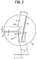
- FIG. 2 is a diagram for describing the inmold labeled type plastic container in a mode for carrying out the invention, and more specifically a diagram showing an enlarge section of a bottom rim 20 (sign (i) in FIG. 1 );
- FIG. 3 is a diagram for describing the inmold labeled type plastic container in another mode for carrying out the invention, and more specifically a diagram showing an enlarged section of a flange part 30 (sign (ii) in FIG. 1 );
- FIGS. 4 show front views of a label for use on the side part and (c) shows a front views of a label for use on the bottom part;
- FIG. 5 show enlarged sectional views of the shape of a flange part in the inmold labeled type plastic container according to the invention
- FIG. 6 shows a sectional view of the inmold labeled type plastic container according to the invention where its content is to be a retort food compatible with a microwave oven;
- FIG. 7 shows a sectional view of the inmold labeled type plastic container according to the invention in the absence of a bottom rim.
- the inmold labeled type plastic container according to the invention has its major characteristic in its bottom rim and flange part, and therefore in the following description the bottom rim will be considered a first characteristic feature and the flange part a second characteristic feature of the invention.
- FIG. 1 is a schematic illustrative diagram for describing one example of molding method for the inmold labeled type plastic container according to the invention.
- the molding method shown in FIG. 1 merely shows one typical example, but is nothing to limit the method of molding the inmold labeled type plastic container according to the invention.
- a molding method of an inmold labeling system for molding the inmold labeling type plastic container according to the invention means a method of simultaneous labeling with the molding of a container using female and male metal molds, by which an inmold label is fitted within a gap resulting from the joining of the female mold and the male mold and then molten resin is extruded into the gap, more specifically a method such as the one shown in FIG. 1 .
- an metal mold for injection molding comprising a male metal mold 1 (hereinafter sometimes referred to as simply “male mold”), a female metal mold 2 (hereinafter sometimes referred to as simply “female mold”), a runner 3 , a gate opening 4 , a vacuum suction device 5 a fitted to the male mold 1 , vacuum suction devices 5 b and 5 b fitted to the female mold 2 and so forth;
- a label R 1 for the side part is so fitted onto the inner wall surface of the female mold 2 as to be tightly stuck to a position corresponding to the whole outer wall surface of the side part of the molded container while fixing it by vacuum suction utilizing the vacuum suction devices 5 b and 5 b and the like
- a label R 2 for the bottom part is so fitted onto the surface in a position corresponding to the bottom part of the male mold 1 while fixing it by vacuum suction utilizing the vacuum suction device 5 a .
- the male mold 1 is fixed to the female mold 2 ; after that, molten resin 6 is injected from the gate opening 4 with a heating cylinder (not shown) into the gap formed by the female mold 2 and the male mold 1 by way of the runner 3 to form a container 7 matching the shape of the gap and to tightly adhere the label R 1 for the side part and the label R 2 for the bottom part in a molten-integrated form to all over the outer wall surface of the body part an all over the inner bottom wall surface of the bottom constituting that container 7 ; after that the molded product, which has been hardened by cooling, is taken out, thereby enabling the inmold labeled type molded container according to the invention to be produced.
- the inmold labeled type plastic container 7 according to the invention formed by this method is characterized in that the relationship between the fluid length L of the injected molten resin and the average wall thickness 5 (not shown) of the container 7 is L/t ⁇ 250.
- the pressure of the molten resin is sufficiently transmitted to the flange part to obtain an inmold labeled type plastic container which is highly accurate and free from unintended unlabeling or wrinkling, and excels in aesthetic design.
- FIG. 2 is a diagram for describing the inmold labeled type plastic container 7 in a mode for carrying out the invention formed by the inmold labeled type plastic container molding method shown in FIG. 1 , and more specifically a diagram showing an enlarge section of a bottom rim 20 (sign (i) in FIG. 1 ).
- the bottom rim 20 is formed in the lower part of the inmold labeled type plastic container 7 according to the invention and, with its dimension x being not less than 0.3 mm but not more than 20 mm, the bottom rim too is characterized by being labeled with a label R 1 similar to that on the-container's side part 8 .
- the tip portion of the label R 1 will be positioned in the vicinity of the joint portion between the container's side part 8 and the container's bottom part 9 , the molten resin will flow over the surface of the label R 1 at the time of molding and adversely affect the aesthetic design of the container 7 .
- the dimension x of the bottom rim 20 is longer than 20 mm, there will be no problem in its relationship to the label R 1 , but eventually the wall thickness (a) of the intersection between the bottom rim 20 and the container's bottom part 9 will increase, sometimes giving rise to a problem, such as the label coming off in the container after injection molding.
- the inmold labeled type plastic container 7 according to the invention is also characterized by relationships of A ⁇ 2 ⁇ B and A ⁇ 2 ⁇ C among the wall thickness (a) of the intersection between the bottom rim 20 and the container's bottom part 9 , the wall thickness (b) of the container's bottom part and the wall thickness (c) of the container's side part.
- the wall thickness (a) of the intersection is in a range of 1.0 to 3.0 mm, and 1.5 mm is particularly preferable in this range. It is preferable for the wall thickness (b) of the container's bottom part to be in a range of 0.5 to 1.5 mm, and 1.0 mm is particularly preferable in this range. Further, it is preferable for the wall thickness (c) of the container's side part to be in a range of 0.5 to 1.5 mm, and 0.7 mm is particularly preferable in this range.
- FIG. 3 is a diagram for describing the inmold labeled type plastic container 7 in another mode for carrying out the invention formed by the inmold labeled type plastic container molding method shown in FIG. 1 , and more specifically a diagram showing an enlarge section of a flange part 30 (sign (ii) in FIG. 1 ).
- the inmold labeled type plastic container 7 has the flange part 30 formed at the upper end of its side part 8 , and is characterized by its dimensions which are not less than 2 mm in flange width y and not less than 0.5 mm in flange thickness z.
- the flange-width y of the flange part 30 By setting the flange-width y of the flange part 30 to not less than 2 mm as in the present invention, it is made possible to make the seal sufficiently strong when the lid member to be stuck to the opening part of the container 7 is to be sealed, and the user will feel nothing awkward even if he or she directly touches it with his or her own mouth. According to the invention, no particular upper limit is prescribed to the flange width y of the flange part 30 , and the width can be set as desired.
- the flange part is enabled to bear the damage it is subjected to when the lid member is to be sealed.
- the invention prescribes no particular upper limit to this flange thickness z either, and the thickness can be set as desired. However, considering the case in which the user directly drinks or eats the content with his or her mouth in direct contact with the container 7 , too great a thickness would conceivably make him or her feel awkward, and therefore about 1.0 mm is preferable.
- the inmold labeling type plastic container 7 is characterized in that the female mold 2 and the male mold 1 are joined at the flange part 30 in the formed container 7 (see reference sign 31 in FIG. 3 ), and the container is fabricated by using the female mold 2 and the male mold 1 so designed that the flange width y′ of a flange part 32 formed by the female mold 1 is smaller than the flange width y of a flange part 33 formed by the male mold 1 .
- the metal molds will be so designed as to create an intentionally disposed level gap S on the flange part 30 as shown in FIG. 3 , the lower side 32 of the flange is invisible when viewed from above the container, and accordingly no problem will arise; the user is likely to have no awkward feeling even when his or her mouth is brought into direct touch with the flange.
- the dimension of the level gap S intentionally disposed to tolerate the deviation arising when the metal molds are combined, if it is substantially equal to the deviation arising when the metal molds are combined, can be set as desired according to the accuracy of the formation apparatus that is actually used. If it is a usual formation apparatus for inmold labeled type plastic containers, the dimension of S will be sufficient if it is set to about 0.05 mm.
- its tip 34 may as well be rounded as illustrated because the female mold 2 and the male mold l are combined.
- the molten resin 6 for use in molding the container 7 according to the invention as described above one of various polyethylene resins for molding use such as high density polyethylene, medium density polyethylene, low density polyethylene or some other kind, polypropylene, polystyrene, polyethylene terephthalate, polycarbonate or the like can be used.
- polyethylene resins for molding use such as high density polyethylene, medium density polyethylene, low density polyethylene or some other kind, polypropylene, polystyrene, polyethylene terephthalate, polycarbonate or the like can be used.
- the thickness is not greater than 150 ⁇ m, any of all the already known in mold label shaving various functions can be used for the purpose.
- labels each having a configuration in which a plurality of thin films are stacked, the thin film positioned on the front face and the thin film positioned on the rear face consist of thin films of the same material, and further at least a resin film layer and a barrier layer having the defined strength or barrier layers having the defined strength are stacked between these thin films; it is further preferable that the thin film positioned on the front face and the thin film positioned on the rear face of the label consist of biaxially oriented polypropylene resin film layers or polyethylene resin film layers, the resin film layers having the defined strength consist of biaxially oriented polyethylene terephthalate film layers, biaxially oriented polyamide film layers or biaxially oriented polypropylene film layers, and the barrier layers consist of metal foil layers, vapor-deposited metal film layers or inorganic vapor-deposited oxide film layers.
- materials to constitute the thin films positioned on the front face and the rear face of the label for instance one of various polyethylene resins for molding use such as high density polyethylene, medium density polyethylene, low density polyethylene, linear (straight chain) polyethylene or some other kind, polypropylene resins, polyester resins, polyamide resins or some other resin films or sheets.
- polyethylene resins co-extruded films or sheets of these resins can also be used.
- films or sheets of the aforementioned resins unoriented or oriented films oriented in the monoaxial or biaxial direction can be used, and their desirable thickness is about 6 to 100 ⁇ m, more preferably about 12 to 50 ⁇ m.
- the fabricated label can be prevented from curling.
- the material to constitute the thin film positioned on the rear face of the label a heat-sealable material which has a property, when the polyethylene resin for molding use constituting the container is injected and extruded to come into contact with it, to melt together and tightly adhere to each other; it is desirable to use as the material to constitute the thin film positioned on the front face of the label a material which can keep the resilience, strength and other characteristics of the label, more desirably what has a rigidity of 5.000 Kg/cm2 in Young's modulus.
- polyester resin polyethylene terephthalate resin
- polyamide resin polyaramid resin
- polypropylene resin polycarbonate resin
- polyaracetal resin some other tough resin films or sheets
- film or sheet of any of the resins stated above performs a function of further reinforcing the function of the material constituting the aforementioned outermost layer, and preferably should have, for instance, rigidity and be excellent in mechanical, physical, chemical and other properties. It is preferable to use as the aforementioned resin films or sheets oriented films oriented in biaxial directions.
- the thickness of the resin films or sheets need not be greater than the minimum required to provide them with sufficient strength, rigidity and other properties; too great a thickness would entail a disadvantage of boosting the label cost or, conversely, too small a thickness would entail poor strength, rigidity and other properties and therefore be undesirable.
- a material having a property to intercept light including sunlight or a material having a property not to allow permeation of water vapor, water, gas or the like can be used, and this may be a single-component base material, a composite base material combining two or more kinds of base materials, or the like.
- what can be used may be, for instance, an aluminum foil having light-intercepting and barriering properties or a resin film on which such a foil is vapor-deposited, a resin film having a vapor-deposited film of an inorganic oxide such as silicon oxide having a barriering property or aluminum oxide, a resin film or sheet of low density polyethylene, medium density polyethylene, high density polyethylene, straight chain low density polyethylene, polypropylene, ethylene-propylene copolymer or the like, a resin film or sheet having a gas-barriering property of polyester resin, polycarbonate resin, nylon resin (polyamide resin), acryl nitrile resin, polyvinyl alcohol, saponified ethylene-acetic vinyl copolymer or the like, or a film or sheet of one or another of various colored resins, which have a property to intercept light, formed by adding a coloring agent such as a pigment augmented with a desired additive or the like to the resin, and mixing and kneading them into a film.
- Any one of these materials singly or in combination with another or more can be used.
- Any of the aforementioned resin films or sheets may have any desired thickness, but it is usually about 6 ⁇ m to 100 ⁇ m, and more preferably about 7 ⁇ m to 30 ⁇ m.
- an aluminum foil of about 6 ⁇ m to 50 ⁇ m in thickness or a resin film on which an aluminum foil is vapor-deposited of about 100 ⁇ to 1000 ⁇ in thickness can be used.
- a resin film to support the aforementioned vapor-deposited film for instance a polyester film, polyamide film, polyolefin film, polycarbonate film, polyvinyl alcohol film, saponified ethylene-acetic vinyl copolymer film or some other film can be used.
- the laminated materials to constitute the label are subject to stringent requirements regarding strength against deformation, strength against drop impact, resistance to pin holes, thermal resistance, sealing performance, qualitative stability, working ease, sanitariness and in other respects, and for this reason other materials satisfying these conditions can be used as desired besides the materials enumerated above; they can be selected from the films or sheets of, for instance, low density polyethylene, medium density polyethylene, high density polyethylene, linear low density polyethylene, polypropylene, ethylene-propylene copolymer, ethylene-acetic vinyl copolymer, monomer resin, ethylene-ethyl acrylate copolymer, ethylene-acrylic acid copolymer or methacrylic acid copolymer, methyl pentene polymer, polybutene resin, vinyl polychloride resin, vinyl polyacetate resin, polyvinylidene chloride resin, vinyl chloride-vinylidene chloride copolymer, poly(meta)
- films such as cellophane or synthetic paper or the like can also be used.
- the aforementioned resin films or sheets can be used unoriented or oriented in uniaxial or biaxial directions. Their thickness can be selected as desired from a range of about a few ⁇ m to 150 ⁇ m and used. Further according to the invention, the resin films or sheets may be in any state, such as extruded film, inflation film or coating film.
- applicable methods include one or another of laminating methods for use in fabricating a usual wrapping material including, for instance, the extrusive laminate method, sand laminate method, co-extrusion laminate method, dry laminate method, solvent-free dry lamination method or some other method.
- pretreatment such as corona treatment, ozone treatment or frame treatment can be applied to the film and, for example, one or another of isocyanate (urethane), polyethylene imine, polybutadiene, organic titanium and other anchor coating agents, or one or another of known anchor coating agents, adhesives and the like including polyurethane, polyacryl, polyester, epoxy, vinyl polyacetate, cellulose or some other adhesive for use with laminates can be used.
- isocyanate urethane
- polyethylene imine polyethylene imine
- polybutadiene organic titanium and other anchor coating agents
- adhesives and the like including polyurethane, polyacryl, polyester, epoxy, vinyl polyacetate, cellulose or some other adhesive for use with laminates can be used.
- an adhesive extrusion resin to constitute the adhesive layer in performing extrusion lamination for instance any of polyethylene, ethylene-(-ethyl acrylate copolymer, polypropylene, polybutene, polyisobutene, polyisobutylene, polybutadiene, polyisoprene, ethylene-methacrylic acid copolymer, copolymers of ethylene and unsaturated carbonic acid such as ethylene-acrylic acid copolymer or acid-denatured polyolefin resin obtained by denaturing one or another of them, ethylene-ethyl acrylate copolymer, ethylene-methyl acrylate copolymer, ionomer resin, ethylene-vinyl acetate copolymer or the like can be used.
- the adhesive to constitute the adhesive layer for dry lamination in specific terms a two-part hardening type urethane adhesive used in dry lamination or the like, polyester urethane adhesive, polyether urethane adhesive, acryl adhesive, polyester adhesive, polyamide adhesive, vinyl polyacetate adhesive, epoxy adhesive, rubber adhesive or some other adhesive can be used.
- FIGS. 4( a ) and ( b ) show front views of the label R 1 for the side part and FIG. 4( c ), a front view of the label R 2 for the bottom part.
- the label R 1 for the side part is in a fan shape, and cuts 42 and 42 may be formed in lower parts of two side edges 41 and 41 of the label R 1 for the side part.
- These cuts 42 and 42 at their maximum length, extend to the parts of the side part 8 (see FIG. 1) matching the bottom rim 20 , and as a result the height h of the cuts 42 and 42 also is substantially equal to the distance from the bottom end of the label R 1 for the side part to the top end of the bottom rim 20 .
- the label R 1 for the side part By providing the label R 1 for the side part with the cuts 42 and 42 in this way, when the label R 1 for the side part is fitted into the female metal mold 2 , the lower parts of the two side edges 41 and 41 of the label R 1 for the side part are prevented from coming into contact with the protruding portion 2 a of the female metal mold 2 (see FIG. 1 ), which would peel off the lower part of this label R 1 for the side part. For this reason, there is no possibility for the injected resin 6 to be caused to flow outside the label R 1 for the side part by the peeling-off of the label R 1 for the side part, and instead the label R 1 for the side part can be arranged in its due position outside the side part 8 .
- the label R 1 for the side part is in a fan shape as shown in FIG. 4( b ), and its four corners may form curved cuts. In this case, the cuts 42 need not be formed. The reason is that, by forming the four corners of the label R 1 for the side part in a curved form, even if it comes into contact with the protruding portion 2 a of the metal mold 2 (see FIG. 1) , the label R 1 will slide and reach its regular position.
- the diameter of the label R 2 for the bottom part may be smaller than the outer diameter D of the side part 8 on the plane of arrangement of the label R 2 for the bottom part and greater than the outer diameter E of the bottom part 9 on the plane of arrangement of the label R 2 for the bottom part.
- E the diameter of the label R 2 for the bottom part
- the diameter of the label R 2 for the bottom part By setting the diameter of the label R 2 for the bottom part larger than the outer diameter E of the bottom part 9 in this way, when the label R 2 for the bottom part is fitted into the female metal mold 2 (see FIG. 1 ), even if the label R 2 for the bottom part somewhat deviates, the bottom part 9 of the container 7 can be sufficiently covered by the label R 2 . As a result, the gas,barriering and other functions of the bottom part 9 can be enhanced. Also, by setting the diameter of the label R 2 for the bottom part smaller than the outer diameter D of the side part 9 , the injected resin 6 can be let smoothly flow around the bottom rim 20 .
- the label R 2 for the bottom part need not be used in every case, and its use can be dispensed with where it is unnecessary (for instance where the container's bottom part requires no aesthetic design or the container's bottom part needs no gas barriering).
- the material of the lid member for sealing the inmold labeling system type plastic container according to the invention. More specifically, any film or sheet of polyester resin, polyamide resin, polyaramid resin, polypropylene resin, polycarbonate resin, polyaracetal resin, fluorine resin or some other tough resin, or of various paper base materials can be used. As films or sheets of the aforementioned resins, unoriented or oriented films oriented in the uniaxial or biaxial direction can be used. Also, like the aforementioned inmold labels R 1 and R 2 , the lid member can be formed in a laminated structure.
- the lid member is to be provided with a property to intercept light including sunlight or a material having a property not to allow permeation of water vapor, water, gas or the like
- materials having such properties can be stacked; what can be used maybe, for instance, an aluminum foil having light-intercepting and barriering properties or a resin film on which such a foil is vapor-deposited, a resin film with a barriering property having a vapor-deposited film of an inorganic oxide such as silicon oxide or aluminum oxide, a resin film or sheet of low density polyethylene, medium density polyethylene, high density polyethylene, straight chain low density polyethylene, polypropylene, ethylene-propylene copolymer or the like, a resin film or sheet having a gas-barriering property of polyester resin, polycarbonate resin, nylon resin (polyamide resin), acryl nitrile resin, polyvinyl alcohol, saponified ethylene-acetic vinyl copolymer or the like, or a film or sheet of one or another of various colored resins having a
- the inmold labeled type plastic container according to the invention can be suitably used as a container applicable to microwave ovens, and in this case the flange part can as well be shaped not only as shown in FIG. 3 but also as shown in FIGS. 5( a ) and ( b ).
- a seal protruding part 50 is disposed on the upper face of the flange part 30 and a reinforcing protruding part 51 hanging from the outer tip of the flange part 30 may also be provided.
- the seal protruding part 50 need not be provided in some cases.
- the flange part 30 may be inclined downward at a fixed angle ⁇ ° to a horizontal line 52 , which is an extension of a horizontal line linking the opening of the container and indicated by a dotted line. It is preferable for this fixed angle ⁇ to be about 1° to 10° and more preferably 2° to 5°.
- Such a flange part facilitates the opening and closing of the container, and therefore is suitable for a container whose content is to be a retort food compatible with a microwave oven.
- FIG. 6 shows a sectional view of the inmold labeled type plastic container according to the invention where its content is to be a retort food compatible with a microwave oven.
- a container body 60 comprises a circumferential side wall part 61 constituting the barrel of the container, a flange part 62 continuous outward from the top end of the circumferential side wall part 61 , a bottom wall part 63 continuous laterally from the bottom end of the circumferential side wall part 61 , and a bottom rim 64 continuous in the perpendicular direction from the bottom end part of the circumferential side wall part 61 .
- the flange part 62 has a configuration in which the flange part 62 constituting the container body 60 is inclined downward from the horizontal line indicated by dotted line L from the top end of the circumferential side wall part 61 and is continuous outward as shown in FIG. 5 .
- annular stacking rib 65 can be disposed on the inner circumferential face of the circumferential side wall part 61 constituting the container body 60 . And according to the invention, by disposing the annular stacking rib 65 as stated above, it is made possible to stack such containers 60 and provides a reinforcing effect to increase the strength of its barrel.
- a container to contain a retort food and to be applied to a microwave oven requires a certain strength (namely it has to bear retorting or boiling); further with a view to ensuring a sufficient drop strength and other properties required of the container, regarding the wall thicknesses of the circumferential side wall part 61 , the flange part 62 and the bottom wall part 63 constituting the container body 60 , it should desirably be such a container injection molded with adjustment to keep the wall thickness T 1 of the circumferential side wall part 61 in a range of 0.6 to 1.2 mm, the wall thickness T 2 of the bottom wall part 3 , 0.7 to 1.3 mm, and the wall thickness T 3 of the flange part 62 , 0.9 to 1.5 mm.
- bottom rim ( 30 or 64 ) is formed in every one the inmold labeled type plastic containers described above, the bottom rim is not necessarily indispensable, but a form shown in FIG. 7 is also acceptable.
- An inmold labeled type plastic container 70 shown in FIG. 7 comprises a flange part 71 , a side wall part 72 hanging from the flange part 71 and a bottom part 73 continuous to the side wall part 72 . Further the outer bottom face of the bottom part 73 constitutes a grounding face. Further, an annular stacking rib 74 erecting from the bottom part 73 of the container is disposed on the inner circumferential face of the side wall part 72 .
- the thickness of the side wall part 72 in the vicinity of the upper part of the annular stacking rib 74 being represented by U 1
- the thickness of the side wall part 72 between the bottom part 73 and the annular stacking rib 74 being represented by U 2
- U 3 it is preferable that they have a relationship of U 3 >U 2 >U 1 .
- the curve of the inner face P 1 of the intersection between the bottom part 73 and the side wall part 72 it is preferable for the curve of the inner face P 1 of the intersection between the bottom part 73 and the side wall part 72 to have its radius r 1 in a range of 1.5 U 1 to 3 U 1 and the curve of the outer face P 2 of the intersection between the bottom part 73 and the side wall part 72 to have its radius r 2 in a range of 1/2 U 3 to 1/4 U 3 .
- the curve of the inner face P 1 in a range around 2.0 U 1 , from 1.7 U 1 to 2.3 U 1 and the curve of the outer face P 2 to have its radius r 2 in a range around 1/3 U 3 .
- U 1 , U 2 and U 3 are in mm units.
- the drop strength of the inmold labeled type plastic container according to the invention is increased.
- the drop strength of the inmold labeled type plastic container according to the invention is further enhanced.
- an inmold labeled type plastic container excelling in aesthetic design and whose label is prevented from being peeled off or rolling onto the surface side of the label (between the inner surface of the female mold and the label) can be provided.
- HDPE M.F.R.: 40 g/10 min
- resin temperature 220° C.
- this resin and a label of 90 ⁇ m in thickness were integrally molded by the molding method for inmold labeled type plastic containers illustrated in FIG. 1 to fabricate an inmold labeled type plastic container of Embodiment 1, and it was filled with a content.
- Thickness of the intersection between the bottom rim and the container's bottom part 1.0 mm
- Thickness of the container's bottom part 1.1 mm
- Thickness of the container's side part 0.77 mm
- volume of the content 240 cc (the content was sterilized with a mist of hydrogen peroxide before the container was filled with it, and the inside of the container was dried).
- the inmold labeled type plastic container of Embodiment 1 was found to be a plastic container excelling in aesthetic design, whose label is prevented from being peeled off or wrinkled.
- the inmold labeled type plastic container of Embodiment 1 excelling in suitability for being filled with and packaging the content, suitability for distribution, preservability and other respects, was not destroyed when it was dropped five times from a height of 50 cm, and found excelling in light interception and, moreover in respects of permeation of oxygen and permeation of humidity.
- polypropylene As the injected resin material for the plastic container body, polypropylene was used and, as the label material a film formed by stacking three layers of polyethylene terephthalate film (12 ⁇ m)/aluminum foil (15 ⁇ m)/polypropylene film (60 ⁇ m) was used.
- This label material after characters and pictures were printed on the PET film as the thin layer positioned on its front (outermost) side and the aluminum foil as the barrier layer was laminated by using an adhesive, was formed into a three-layered film with the polypropylene film as the thin layer positioned on its rear (innermost) side being laminated by using an adhesive, and punched into prescribed shapes (a fan shape for the side label and a round having a gate hole at the center for the bottom label).
- these labels (the side label R 1 and the bottom label R 2 ) were arranged on the side face and the bottom face of the female mold 2 and, after the male mold 1 was pressed in from above, the resin 6 was injected into the cavity through the gate 4 to perform usual injection molding of inmold labels.
- this label material is the same material as the resin of the container body, the label material and the container body can be integrated without using an adhesive.
- Oxygen Water vapor permeability permeability Barrier layer (cc/pkg ⁇ day ⁇ atm) * (g/pkg ⁇ day) * PET with silicon oxide 0.07 0.0041 vapor-deposited thereon Polyvinylidene chloride film 0.08 0.0043 Aluminum foil 0.06 0.00088 None 6.70 0.01 * Measuring methods: For oxygen permeability 23° C. in temperature, 90% RH in humidity, purged for 3 days; MOCON's Oxtran used For water vapor permeability Calcium chloride weight method, measured for 6 days; 40° C. in temperature, 90% RH in humidity
- the extent of curling of the label material affects the yield of injection molding. Namely, the smaller the curling of the label material, the higher the yield.
- the laminated structure of the label material in a symmetrical pattern centering on the central layer.
- the label material having the configuration of (1), (2) and (5) layers it is possible to configure the laminated structure in a symmetrical pattern centering on the central layer, and the label material of (3) and (4) can also be considered to have a symmetrical laminated structure if the polyethylene terephthalate film and the polyethylene terephthalate film on which silicon oxide is vapor-deposited are considered a single polyethylene terephthalate film. For this reason, the curling of the label material was successfully reduced at the time of punching. Where the label material having the configuration of (1) through (5) layers was used, both the gas barriering characteristic and the tight adhesiveness to the injected resin were satisfactory.
- a face of a biaxially oriented polypropylene film of 30 ⁇ m in thickness was coated with a polyurethane adhesive to a thickness of 4 g/m 2 (in a dry state) to form an adhesive layer, and a biaxially oriented polyethylene terephthalate film of 12 ⁇ m in thickness, on one face of which a prescribed print pattern was printed to form a printed layer was dry-laminated over a face of the adhesive layer.
- this biaxially oriented polyethylene terephthalate film was coated with a polyurethane adhesive to a thickness of 4 g/m 2 (in a dry state) in the same way as above to form an adhesive layer, and further a biaxially oriented polyethylene terephthalate film on which silicon oxide of 12 ⁇ m in thickness was vapor-deposited was dry-laminated on a face of the adhesive layer.
- the face of the biaxially oriented polyethylene terephthalate film on which silicon oxide was vapor-deposited was coated with a polyurethane adhesive to a thickness of 4 g/m 2 (in a dry state) in the same way as above to form an adhesive layer, and then a biaxially oriented film of 30 ⁇ m in thickness, mainly consisting of polypropylene and having a heat seal layer, was dry-laminated over a face of the adhesive layer to fabricate a laminated material for label formation.
- a label for the outer circumferential face to be tightly adhered to the whole outer wall face of the circumferential side wall part constituting an injection molded container of prescribed dimensions and similarly a label for the bottom face (perforated label) to be tightly adhered to the whole outer wall face of the bottom wall part constituting the injection molded container were fabricated by punching.
- the label for the outer circumferential face and the label for the bottom face fabricated as described above were so fitted to the inner wall face of the metal mold that its biaxially oriented film face having the heat sealing function comes into contact with the molded resin while vacuum-sucking to fix it by utilizing a vacuum suction device or the like.
- the male metal mold was fixed to the female metal mold; after that polypropylene resin melted by a heating cylinder was injected from a gate opening by way of a runner into a space formed by the female metal mold and the male metal mold to form a container matching the shape of the space between the metal molds; at the same time, the label was closely adhered to the outer wall face of the circumferential side wall part of the barrel constituting that container and the outer wall face of the bottom wall part by melting integration, followed by cooling and hardening, and the molded product was taken out to fabricate an inmold labeled injection molded container for retort food according to the invention (see FIG. 6 ).
- the capacity of the container was 320 cc, and the flange part constituting the injection molded container was disposed with a downward inclination of 3° to the horizontal line of the opening.
- the inmold labeled injection molded container for retort food fabricated as described above was filled through its opening with curry roux (290 g) as the content to fill it into a package; after that, over its opening, a biaxially oriented polyethylene terephthalate film whose internal face consisted of an unoriented polypropylene resin film having a heat sealing function and, over which silicon oxide was further vapor-deposited as a barriering base, was stacked; it was further sealed with a lid member formed by stacking a biaxially oriented polyethylene terephthalate film of 12 ⁇ m in thickness as the base film to fabricate a sealed packaged product.
- the sealed packaged product was put into a retort boiler to undergo retort processing (sterilization with heat) under retorting conditions of 120° C. in temperature, 2.1 Kgf/cm 2 in pressure and 30 minutes in duration to fabricate a packaged product having gone through retort processing.
- the packaged product having gone through retort processing manifested no deformation of the container body or any other detect, and was found excelling in packaging suitability, retorting suitability, distribution suitability, preservative suitability and other respects.
- the packaging container constituting this packaged product was not destroyed when it was dropped five times from a height of 50 cm, and found excelling in oxygen permeability and humidity permeability among other properties.
- T 1 (Ta) was 0.95 mm, T 1 , 1.0 mm, T 2 , 1.1 mm, T 3 , 1.2 mm, and r 1 , 0.5 mm.
- the container was filled with 310 cc of tomato paste as its content, and sealed with the lid member over the opening.
- This container was subjected to boiling sterilization at 95° C. for 60 minutes to provide a boil-treated package product.
- This boil-treated package product manifested no deformation of the container body or any other detect, and was found excelling in packaging suitability, retorting suitability, distribution suitability, preservative suitability and other respects.
- the packaging container constituting this packaged product was not destroyed when it was dropped five times from a height of 50 cm, and found excelling in oxygen permeability and humidity permeability among other properties.
- the tomato paste which was heated for one minute in a 500 W microwave oven after the lid material of the packaged product was peeled off became just hot enough to eat, suffering no deformation of the container,or any other trouble, and the container was thus found also excellent for use involving boiling.
Applications Claiming Priority (1)
| Application Number | Priority Date | Filing Date | Title |
|---|---|---|---|
| PCT/JP2003/007804 WO2004113180A1 (ja) | 2003-06-19 | 2003-06-19 | インモールドラベル方式プラスチック容器 |
Publications (2)
| Publication Number | Publication Date |
|---|---|
| US20060131306A1 US20060131306A1 (en) | 2006-06-22 |
| US7588157B2 true US7588157B2 (en) | 2009-09-15 |
Family
ID=33524158
Family Applications (1)
| Application Number | Title | Priority Date | Filing Date |
|---|---|---|---|
| US10/561,353 Expired - Fee Related US7588157B2 (en) | 2003-06-19 | 2003-06-19 | In-mold label system plastic container |
Country Status (7)
| Country | Link |
|---|---|
| US (1) | US7588157B2 (ja) |
| EP (1) | EP1637457B1 (ja) |
| JP (1) | JP4527056B2 (ja) |
| KR (1) | KR100997168B1 (ja) |
| CN (1) | CN100528694C (ja) |
| AU (1) | AU2003244314A1 (ja) |
| WO (1) | WO2004113180A1 (ja) |
Cited By (1)
| Publication number | Priority date | Publication date | Assignee | Title |
|---|---|---|---|---|
| WO2012005761A2 (en) | 2010-07-09 | 2012-01-12 | Nestec S.A. | Labeled containers and processes for producing labeled containers |
Families Citing this family (40)
| Publication number | Priority date | Publication date | Assignee | Title |
|---|---|---|---|---|
| ES2218361T3 (es) | 2001-01-30 | 2004-11-16 | Seda S.P.A. | Envase de carton para bebidas y su procedimiento. |
| US7665672B2 (en) | 2004-01-16 | 2010-02-23 | Illinois Tool Works Inc. | Antistatic paint cup |
| US7086549B2 (en) | 2004-01-16 | 2006-08-08 | Illinois Tool Works Inc. | Fluid supply assembly |
| US7165732B2 (en) | 2004-01-16 | 2007-01-23 | Illinois Tool Works Inc. | Adapter assembly for a fluid supply assembly |
| US20050258271A1 (en) * | 2004-05-18 | 2005-11-24 | Kosmyna Michael J | Disposable paint cup |
| US7766250B2 (en) | 2004-06-01 | 2010-08-03 | Illinois Tool Works Inc. | Antistatic paint cup |
| US7757972B2 (en) | 2004-06-03 | 2010-07-20 | Illinois Tool Works Inc. | Conversion adapter for a fluid supply assembly |
| US7353964B2 (en) | 2004-06-10 | 2008-04-08 | Illinois Tool Works Inc. | Fluid supply assembly |
| BRPI0601188B1 (pt) | 2005-04-15 | 2018-06-26 | Seda S.P.A. | Recipiente isolado; método de fabricar o mesmo e aparelho para a fabricação |
| JP4951875B2 (ja) * | 2005-05-13 | 2012-06-13 | 大日本印刷株式会社 | プラスチック容器 |
| DE202005014177U1 (de) | 2005-09-08 | 2005-11-17 | Seda S.P.A., Arzano | Doppelwandiger Becher |
| PL1785370T5 (pl) | 2005-11-11 | 2014-06-30 | Seda Spa | Izolowany kubek |
| EP1785265A1 (en) | 2005-11-14 | 2007-05-16 | SEDA S.p.A. | Device for producing a stacking projection on a container wall and container with same |
| IL179588A (en) | 2006-11-26 | 2011-11-30 | Keter Plastic Ltd | Injection molding method and system and molded products manufactured thereby |
| DE202006018406U1 (de) | 2006-12-05 | 2008-04-10 | Seda S.P.A. | Verpackung |
| FR2922806B1 (fr) | 2007-10-26 | 2009-12-18 | Alcan Packaging Beauty Serv | Procede et dispositif pour fabriquer en grande cadence des corps en matiere plastique dont la surface exterieure est munie d'une etiquette |
| DE102007054661A1 (de) * | 2007-11-14 | 2009-05-20 | Dr. Jaeniche Gmbh & Co Kg | Rohrförmiger Behälter |
| JP5177390B2 (ja) * | 2008-02-29 | 2013-04-03 | 株式会社吉野工業所 | カップ状容器 |
| JP5217549B2 (ja) * | 2008-03-24 | 2013-06-19 | 大日本印刷株式会社 | インモールドラベル方式プラスチック容器 |
| US20100227094A1 (en) * | 2009-03-09 | 2010-09-09 | Ipl, Inc. | Oxygen barrier molded container and method for production thereof |
| JP2011073700A (ja) * | 2009-09-29 | 2011-04-14 | Dainippon Printing Co Ltd | インモールドラベル容器 |
| GB2478732B (en) * | 2010-03-15 | 2014-08-20 | Kraft Foods R & D Inc | Improvements in injection moulding |
| RU2568082C2 (ru) | 2010-05-12 | 2015-11-10 | Нестек С.А. | Капсула, система и способ для приготовления напитка центрифугированием |
| JP5533546B2 (ja) * | 2010-10-18 | 2014-06-25 | 大日本印刷株式会社 | インモールドラベル容器および蓋材付きインモールドラベル容器 |
| KR200470000Y1 (ko) * | 2011-09-08 | 2013-11-19 | 오상자이엘 주식회사 | 탄성력을 가지는 테두리부가 형성된 일회성 식품포장용기 |
| US9096347B2 (en) | 2012-03-20 | 2015-08-04 | Berry Plastics Corporation | Stand-up Package |
| DE102012103082B4 (de) * | 2012-04-11 | 2014-11-27 | Knauer Holding Gmbh & Co. Kg | Aus Kunststoff gespritztes, mittels eines IML-Verfahrens hergestelltesBehältnis |
| US10286628B2 (en) * | 2012-05-14 | 2019-05-14 | Taylor Communications, Inc. | Composite film having barrier properties for use as in-mold labels, article with in-mold labels, and methods of making same |
| US20130344268A1 (en) * | 2012-06-26 | 2013-12-26 | Alfred CHOI | Moulded article and label therefor |
| US9145251B2 (en) * | 2012-10-26 | 2015-09-29 | Berry Plastics Corporation | Package |
| KR101426548B1 (ko) * | 2013-03-05 | 2014-08-06 | 주식회사 유라 | 사출 성형장치 |
| US20150084236A1 (en) * | 2013-09-20 | 2015-03-26 | Precision Press, Inc. | Composite film assemblies having sealing and barrier properties for use as in-mold labels, articles with in-mold labels, and methods of making same |
| ES2531729B1 (es) * | 2014-11-14 | 2015-12-22 | Industrias Técnicas Del Cable, S.L. | Material laminar para etiquetado en molde de envases y envase para la preparación de bebidas etiquetado en molde con dicho material laminar |
| US10532872B2 (en) | 2014-12-08 | 2020-01-14 | Berry Plastics Corporation | Package |
| JP2017132486A (ja) * | 2016-01-25 | 2017-08-03 | 三宝化成工業株式会社 | 飲料用容器 |
| JP6959605B2 (ja) * | 2017-03-02 | 2021-11-02 | 株式会社アプリス | 断熱容器 |
| CN108945693A (zh) * | 2018-08-07 | 2018-12-07 | 上海珂明注塑系统科技有限公司 | 一种高阻隔容器及其制备方法 |
| JP7282300B2 (ja) * | 2018-08-31 | 2023-05-29 | 大日本印刷株式会社 | 包装材料用積層体および包装材料 |
| TW202110613A (zh) * | 2019-06-14 | 2021-03-16 | 日商阪東化學股份有限公司 | 模內標籤、模內標籤的製造方法、帶有模內標籤的容器以及帶有模內標籤的容器的製造方法 |
| CN115489075A (zh) * | 2019-08-27 | 2022-12-20 | 深圳硅基仿生科技有限公司 | 注塑成型方法 |
Citations (44)
| Publication number | Priority date | Publication date | Assignee | Title |
|---|---|---|---|---|
| US1907797A (en) * | 1930-02-05 | 1933-05-09 | Seeley Tube & Box Company | Container |
| US1955851A (en) * | 1929-09-03 | 1934-04-24 | Milprint Products Company | Package and container |
| US3169689A (en) * | 1963-05-13 | 1965-02-16 | Traders Leasing Ltd | Thin walled container |
| US3171539A (en) * | 1959-01-30 | 1965-03-02 | Grace W R & Co | Film for packaging |
| US3231128A (en) * | 1964-02-19 | 1966-01-25 | Max Klein Inc | Plastic basket construction |
| US3382136A (en) * | 1962-01-08 | 1968-05-07 | Union Carbide Corp | Moldable laminates of metal and plastics |
| US3381818A (en) * | 1962-02-12 | 1968-05-07 | Procter & Gamble | Dentifrice package having a laminated film body |
| US3391823A (en) * | 1965-03-02 | 1968-07-09 | Vasco Ind Corp | Rigidified polyethene structures and method of producing them |
| US3685734A (en) * | 1971-02-19 | 1972-08-22 | Minnesota Mining & Mfg | Controlled fragrance release device |
| US3717544A (en) * | 1970-09-14 | 1973-02-20 | E Valyl | Lined plastic articles |
| US3776413A (en) * | 1972-02-14 | 1973-12-04 | J Myers | Ornamental container |
| US3776375A (en) * | 1972-01-25 | 1973-12-04 | Packaging Ind Inc | Free-standing blister package |
| JPS5358544A (en) * | 1976-11-08 | 1978-05-26 | Sharp Corp | Formation of coating films on cooking utensils |
| US4289817A (en) * | 1970-09-14 | 1981-09-15 | Valyi Emery I | Decorated multilayered hollow plastic container |
| EP0041713A1 (en) * | 1980-06-09 | 1981-12-16 | Nihon Matai Company Limited | Container for strong drinks |
| JPS5764530A (en) | 1980-10-08 | 1982-04-19 | Toshiba Mach Co Ltd | Metal mold for plastic material molded vessel |
| GB2122874A (en) * | 1982-06-15 | 1984-01-25 | Mono Containers Ltd | Receptacles etc. with relatively rotatable walls |
| JPS5950931A (ja) * | 1982-09-17 | 1984-03-24 | Shimamoto Seisakusho:Kk | 金属製容器の製法 |
| JPS60154216A (ja) | 1984-01-25 | 1985-08-13 | Hitachi Ltd | 波長選択型光分波分配装置 |
| US4640853A (en) * | 1985-08-12 | 1987-02-03 | Shell Oil Company | Fiber wound plastic beverage can |
| JPH0252712A (ja) | 1988-08-17 | 1990-02-22 | Mitsui Toatsu Chem Inc | 湯ジワの少ない成形品 |
| US4909411A (en) * | 1989-02-13 | 1990-03-20 | Showa Denko Kabushiki Kaisha | Container |
| JPH03197126A (ja) * | 1989-12-27 | 1991-08-28 | Toppan Printing Co Ltd | 多層プラスチック容器 |
| US5193265A (en) * | 1990-04-26 | 1993-03-16 | Alusuisse-Lonza Services Ltd. | Method of producing a cup-shaped, sterilizable container |
| JPH05112351A (ja) * | 1991-10-17 | 1993-05-07 | Dainippon Printing Co Ltd | ホログラムを形成した成形品 |
| US5257709A (en) * | 1988-03-29 | 1993-11-02 | Dai Nippon Insatsu Kabushiki Kaisha | Container provided with metallic cover and method and apparatus for manufacturing the same |
| JPH07137109A (ja) | 1993-11-16 | 1995-05-30 | Sekisui Chem Co Ltd | 射出成形品のゲート決定装置 |
| JPH08132477A (ja) | 1994-09-14 | 1996-05-28 | Dainippon Printing Co Ltd | インモールドラベル容器およびその製法 |
| JPH08197574A (ja) | 1995-01-31 | 1996-08-06 | Snow Brand Milk Prod Co Ltd | インモールドラベリング容器 |
| JPH09174595A (ja) | 1995-12-28 | 1997-07-08 | Nitsupura Kk | バリヤ性インモールドラベリング容器及びその製造方法 |
| US5804270A (en) * | 1992-08-26 | 1998-09-08 | Kuraray Co., Ltd. | Collapsible tube and its head |
| JPH11105067A (ja) | 1997-10-07 | 1999-04-20 | Dainippon Printing Co Ltd | インモールドラベル容器 |
| JP2000142747A (ja) | 1998-11-13 | 2000-05-23 | Dainippon Printing Co Ltd | 蓋装置および密封容器 |
| JP2000178364A (ja) | 1998-12-21 | 2000-06-27 | Tokuyama Corp | インモールドラベル用フィルム |
| JP2000177784A (ja) | 1998-12-17 | 2000-06-27 | Dainippon Printing Co Ltd | 電子レンジ用射出成形容器 |
| JP2001010677A (ja) | 1999-06-29 | 2001-01-16 | Nippon Del Monte Corp | 電子レンジ用容器 |
| US6199713B1 (en) * | 1995-07-28 | 2001-03-13 | Henkel Nederland B.V. | Reusable container having a protective coating and method for the recovery thereof |
| US6341712B1 (en) * | 2000-03-01 | 2002-01-29 | Ja-Ling Huang | Multi-layer container |
| JP2002211575A (ja) | 2001-01-23 | 2002-07-31 | Toppan Printing Co Ltd | バリア性インモールドラベル容器 |
| US20020150706A1 (en) * | 1999-07-23 | 2002-10-17 | Yopo Corporation | Labeled resin bottle |
| US20030024162A1 (en) * | 1997-09-19 | 2003-02-06 | Weder Donald E. | Shape sustaining pot cover and method for producing same |
| JP2003128037A (ja) | 2001-10-16 | 2003-05-08 | Hashimoto Forming Ind Co Ltd | 合成樹脂製容器とその製造方法 |
| JP2003170920A (ja) | 2001-12-06 | 2003-06-17 | Risu Pack Co Ltd | インモールド容器 |
| US20030196715A1 (en) * | 2001-06-01 | 2003-10-23 | Shunji Sakamoto | Fuel tank or fuel pipe exhibiting excellent corrosion resistance and method for manufacturing the same |
Family Cites Families (1)
| Publication number | Priority date | Publication date | Assignee | Title |
|---|---|---|---|---|
| JPS60154216U (ja) * | 1984-03-23 | 1985-10-15 | 東洋製罐株式会社 | 射出成形プラスチツク容器 |
-
2003
- 2003-06-19 EP EP03817199A patent/EP1637457B1/en not_active Expired - Lifetime
- 2003-06-19 CN CNB038266296A patent/CN100528694C/zh not_active Expired - Fee Related
- 2003-06-19 JP JP2005500899A patent/JP4527056B2/ja not_active Expired - Fee Related
- 2003-06-19 AU AU2003244314A patent/AU2003244314A1/en not_active Abandoned
- 2003-06-19 WO PCT/JP2003/007804 patent/WO2004113180A1/ja active Application Filing
- 2003-06-19 KR KR1020057024387A patent/KR100997168B1/ko active IP Right Grant
- 2003-06-19 US US10/561,353 patent/US7588157B2/en not_active Expired - Fee Related
Patent Citations (44)
| Publication number | Priority date | Publication date | Assignee | Title |
|---|---|---|---|---|
| US1955851A (en) * | 1929-09-03 | 1934-04-24 | Milprint Products Company | Package and container |
| US1907797A (en) * | 1930-02-05 | 1933-05-09 | Seeley Tube & Box Company | Container |
| US3171539A (en) * | 1959-01-30 | 1965-03-02 | Grace W R & Co | Film for packaging |
| US3382136A (en) * | 1962-01-08 | 1968-05-07 | Union Carbide Corp | Moldable laminates of metal and plastics |
| US3381818A (en) * | 1962-02-12 | 1968-05-07 | Procter & Gamble | Dentifrice package having a laminated film body |
| US3169689A (en) * | 1963-05-13 | 1965-02-16 | Traders Leasing Ltd | Thin walled container |
| US3231128A (en) * | 1964-02-19 | 1966-01-25 | Max Klein Inc | Plastic basket construction |
| US3391823A (en) * | 1965-03-02 | 1968-07-09 | Vasco Ind Corp | Rigidified polyethene structures and method of producing them |
| US4289817A (en) * | 1970-09-14 | 1981-09-15 | Valyi Emery I | Decorated multilayered hollow plastic container |
| US3717544A (en) * | 1970-09-14 | 1973-02-20 | E Valyl | Lined plastic articles |
| US3685734A (en) * | 1971-02-19 | 1972-08-22 | Minnesota Mining & Mfg | Controlled fragrance release device |
| US3776375A (en) * | 1972-01-25 | 1973-12-04 | Packaging Ind Inc | Free-standing blister package |
| US3776413A (en) * | 1972-02-14 | 1973-12-04 | J Myers | Ornamental container |
| JPS5358544A (en) * | 1976-11-08 | 1978-05-26 | Sharp Corp | Formation of coating films on cooking utensils |
| EP0041713A1 (en) * | 1980-06-09 | 1981-12-16 | Nihon Matai Company Limited | Container for strong drinks |
| JPS5764530A (en) | 1980-10-08 | 1982-04-19 | Toshiba Mach Co Ltd | Metal mold for plastic material molded vessel |
| GB2122874A (en) * | 1982-06-15 | 1984-01-25 | Mono Containers Ltd | Receptacles etc. with relatively rotatable walls |
| JPS5950931A (ja) * | 1982-09-17 | 1984-03-24 | Shimamoto Seisakusho:Kk | 金属製容器の製法 |
| JPS60154216A (ja) | 1984-01-25 | 1985-08-13 | Hitachi Ltd | 波長選択型光分波分配装置 |
| US4640853A (en) * | 1985-08-12 | 1987-02-03 | Shell Oil Company | Fiber wound plastic beverage can |
| US5257709A (en) * | 1988-03-29 | 1993-11-02 | Dai Nippon Insatsu Kabushiki Kaisha | Container provided with metallic cover and method and apparatus for manufacturing the same |
| JPH0252712A (ja) | 1988-08-17 | 1990-02-22 | Mitsui Toatsu Chem Inc | 湯ジワの少ない成形品 |
| US4909411A (en) * | 1989-02-13 | 1990-03-20 | Showa Denko Kabushiki Kaisha | Container |
| JPH03197126A (ja) * | 1989-12-27 | 1991-08-28 | Toppan Printing Co Ltd | 多層プラスチック容器 |
| US5193265A (en) * | 1990-04-26 | 1993-03-16 | Alusuisse-Lonza Services Ltd. | Method of producing a cup-shaped, sterilizable container |
| JPH05112351A (ja) * | 1991-10-17 | 1993-05-07 | Dainippon Printing Co Ltd | ホログラムを形成した成形品 |
| US5804270A (en) * | 1992-08-26 | 1998-09-08 | Kuraray Co., Ltd. | Collapsible tube and its head |
| JPH07137109A (ja) | 1993-11-16 | 1995-05-30 | Sekisui Chem Co Ltd | 射出成形品のゲート決定装置 |
| JPH08132477A (ja) | 1994-09-14 | 1996-05-28 | Dainippon Printing Co Ltd | インモールドラベル容器およびその製法 |
| JPH08197574A (ja) | 1995-01-31 | 1996-08-06 | Snow Brand Milk Prod Co Ltd | インモールドラベリング容器 |
| US6199713B1 (en) * | 1995-07-28 | 2001-03-13 | Henkel Nederland B.V. | Reusable container having a protective coating and method for the recovery thereof |
| JPH09174595A (ja) | 1995-12-28 | 1997-07-08 | Nitsupura Kk | バリヤ性インモールドラベリング容器及びその製造方法 |
| US20030024162A1 (en) * | 1997-09-19 | 2003-02-06 | Weder Donald E. | Shape sustaining pot cover and method for producing same |
| JPH11105067A (ja) | 1997-10-07 | 1999-04-20 | Dainippon Printing Co Ltd | インモールドラベル容器 |
| JP2000142747A (ja) | 1998-11-13 | 2000-05-23 | Dainippon Printing Co Ltd | 蓋装置および密封容器 |
| JP2000177784A (ja) | 1998-12-17 | 2000-06-27 | Dainippon Printing Co Ltd | 電子レンジ用射出成形容器 |
| JP2000178364A (ja) | 1998-12-21 | 2000-06-27 | Tokuyama Corp | インモールドラベル用フィルム |
| JP2001010677A (ja) | 1999-06-29 | 2001-01-16 | Nippon Del Monte Corp | 電子レンジ用容器 |
| US20020150706A1 (en) * | 1999-07-23 | 2002-10-17 | Yopo Corporation | Labeled resin bottle |
| US6341712B1 (en) * | 2000-03-01 | 2002-01-29 | Ja-Ling Huang | Multi-layer container |
| JP2002211575A (ja) | 2001-01-23 | 2002-07-31 | Toppan Printing Co Ltd | バリア性インモールドラベル容器 |
| US20030196715A1 (en) * | 2001-06-01 | 2003-10-23 | Shunji Sakamoto | Fuel tank or fuel pipe exhibiting excellent corrosion resistance and method for manufacturing the same |
| JP2003128037A (ja) | 2001-10-16 | 2003-05-08 | Hashimoto Forming Ind Co Ltd | 合成樹脂製容器とその製造方法 |
| JP2003170920A (ja) | 2001-12-06 | 2003-06-17 | Risu Pack Co Ltd | インモールド容器 |
Non-Patent Citations (1)
| Title |
|---|
| European Search Report: PCT/JP0307804. |
Cited By (1)
| Publication number | Priority date | Publication date | Assignee | Title |
|---|---|---|---|---|
| WO2012005761A2 (en) | 2010-07-09 | 2012-01-12 | Nestec S.A. | Labeled containers and processes for producing labeled containers |
Also Published As
| Publication number | Publication date |
|---|---|
| KR100997168B1 (ko) | 2010-11-29 |
| EP1637457A1 (en) | 2006-03-22 |
| EP1637457B1 (en) | 2011-09-14 |
| CN1787949A (zh) | 2006-06-14 |
| US20060131306A1 (en) | 2006-06-22 |
| EP1637457A4 (en) | 2008-11-19 |
| WO2004113180A1 (ja) | 2004-12-29 |
| KR20060035625A (ko) | 2006-04-26 |
| AU2003244314A1 (en) | 2005-01-04 |
| JP4527056B2 (ja) | 2010-08-18 |
| JPWO2004113180A1 (ja) | 2006-07-27 |
| CN100528694C (zh) | 2009-08-19 |
Similar Documents
| Publication | Publication Date | Title |
|---|---|---|
| US7588157B2 (en) | In-mold label system plastic container | |
| US5968616A (en) | Compound container | |
| US20050040181A1 (en) | Spout for pouch and plastic pouch with spout fixed thereto | |
| WO2003093009A3 (en) | Barrier laminate structure for packaging beverages | |
| JP4220044B2 (ja) | 電子レンジ用射出成形容器 | |
| JP4641078B2 (ja) | 注出具及び注出具付き包装袋 | |
| JP4270621B2 (ja) | レトルト用射出成形容器 | |
| JP3950509B2 (ja) | 多層シート及び容器 | |
| US20050276940A1 (en) | Lidstock material having improved sealability and peelability to wide classes of materials | |
| JP2004196344A (ja) | インモールドラベル成形カップ及びその製造方法 | |
| JPH0482101B2 (ja) | ||
| JPH1128741A (ja) | インモ−ルドラベリング成形容器 | |
| JP4459542B2 (ja) | 包装容器 | |
| JP5509551B2 (ja) | ロンデル成形体用積層体の製造方法、ロンデル成形体の製造方法、及びチューブ容器の製造方法 | |
| JP2005035568A (ja) | 電子レンジ対応包装容器 | |
| JP2021049995A (ja) | 蓋体および蓋体付きカップ状容器 | |
| JP4357851B2 (ja) | 複合容器 | |
| JPS6345304Y2 (ja) | ||
| JP3546940B2 (ja) | 密封包装体 | |
| JP2000128229A (ja) | 包装用積層体及び易開封性包装体 | |
| JPH074190Y2 (ja) | ラベル付中空容器 | |
| JP2003237841A (ja) | 液体・粘体用包装体 | |
| JP2769564B2 (ja) | 多層構造物及び易開封性容器 | |
| JPH11227733A (ja) | 射出成形容器 | |
| JPH02184883A (ja) | 型内ラベル貼着用ラベル及びラベル付プラスチック容器 |
Legal Events
| Date | Code | Title | Description |
|---|---|---|---|
| AS | Assignment |
Owner name: DAI NIPPON PRINTING CO., LTD., JAPAN Free format text: ASSIGNMENT OF ASSIGNORS INTEREST;ASSIGNOR:SHINOGI, NORIKAZU;REEL/FRAME:017362/0409 Effective date: 20051209 |
|
| FEPP | Fee payment procedure |
Free format text: PAYOR NUMBER ASSIGNED (ORIGINAL EVENT CODE: ASPN); ENTITY STATUS OF PATENT OWNER: LARGE ENTITY |
|
| REMI | Maintenance fee reminder mailed | ||
| LAPS | Lapse for failure to pay maintenance fees | ||
| STCH | Information on status: patent discontinuation |
Free format text: PATENT EXPIRED DUE TO NONPAYMENT OF MAINTENANCE FEES UNDER 37 CFR 1.362 |
|
| FP | Lapsed due to failure to pay maintenance fee |
Effective date: 20130915 |