US7510404B2 - Fixing structure and control device using that fixing structure - Google Patents
Fixing structure and control device using that fixing structure Download PDFInfo
- Publication number
- US7510404B2 US7510404B2 US10/997,668 US99766804A US7510404B2 US 7510404 B2 US7510404 B2 US 7510404B2 US 99766804 A US99766804 A US 99766804A US 7510404 B2 US7510404 B2 US 7510404B2
- Authority
- US
- United States
- Prior art keywords
- housing
- circuit board
- impact
- board
- mounting
- Prior art date
- Legal status (The legal status is an assumption and is not a legal conclusion. Google has not performed a legal analysis and makes no representation as to the accuracy of the status listed.)
- Expired - Fee Related
Links
- 230000006378 damage Effects 0.000 abstract description 3
- 238000000034 method Methods 0.000 description 6
- 238000004512 die casting Methods 0.000 description 5
- 239000000463 material Substances 0.000 description 4
- 238000001514 detection method Methods 0.000 description 3
- 230000000644 propagated effect Effects 0.000 description 3
- 230000003014 reinforcing effect Effects 0.000 description 3
- 230000015572 biosynthetic process Effects 0.000 description 2
- 238000010586 diagram Methods 0.000 description 2
- 230000005540 biological transmission Effects 0.000 description 1
- 238000003780 insertion Methods 0.000 description 1
- 230000037431 insertion Effects 0.000 description 1
- 238000012986 modification Methods 0.000 description 1
- 230000004048 modification Effects 0.000 description 1
- 238000010137 moulding (plastic) Methods 0.000 description 1
- 239000000758 substrate Substances 0.000 description 1
Images


Classifications
-
- B—PERFORMING OPERATIONS; TRANSPORTING
- B60—VEHICLES IN GENERAL
- B60R—VEHICLES, VEHICLE FITTINGS, OR VEHICLE PARTS, NOT OTHERWISE PROVIDED FOR
- B60R16/00—Electric or fluid circuits specially adapted for vehicles and not otherwise provided for; Arrangement of elements of electric or fluid circuits specially adapted for vehicles and not otherwise provided for
- B60R16/02—Electric or fluid circuits specially adapted for vehicles and not otherwise provided for; Arrangement of elements of electric or fluid circuits specially adapted for vehicles and not otherwise provided for electric constitutive elements
- B60R16/0207—Wire harnesses
- B60R16/0215—Protecting, fastening and routing means therefor
-
- B—PERFORMING OPERATIONS; TRANSPORTING
- B60—VEHICLES IN GENERAL
- B60R—VEHICLES, VEHICLE FITTINGS, OR VEHICLE PARTS, NOT OTHERWISE PROVIDED FOR
- B60R16/00—Electric or fluid circuits specially adapted for vehicles and not otherwise provided for; Arrangement of elements of electric or fluid circuits specially adapted for vehicles and not otherwise provided for
- B60R16/02—Electric or fluid circuits specially adapted for vehicles and not otherwise provided for; Arrangement of elements of electric or fluid circuits specially adapted for vehicles and not otherwise provided for electric constitutive elements
- B60R16/023—Electric or fluid circuits specially adapted for vehicles and not otherwise provided for; Arrangement of elements of electric or fluid circuits specially adapted for vehicles and not otherwise provided for electric constitutive elements for transmission of signals between vehicle parts or subsystems
- B60R16/0239—Electronic boxes
-
- H—ELECTRICITY
- H05—ELECTRIC TECHNIQUES NOT OTHERWISE PROVIDED FOR
- H05K—PRINTED CIRCUITS; CASINGS OR CONSTRUCTIONAL DETAILS OF ELECTRIC APPARATUS; MANUFACTURE OF ASSEMBLAGES OF ELECTRICAL COMPONENTS
- H05K5/00—Casings, cabinets or drawers for electric apparatus
- H05K5/0026—Casings, cabinets or drawers for electric apparatus provided with connectors and printed circuit boards [PCB], e.g. automotive electronic control units
- H05K5/0073—Casings, cabinets or drawers for electric apparatus provided with connectors and printed circuit boards [PCB], e.g. automotive electronic control units having specific features for mounting the housing on an external structure
-
- H—ELECTRICITY
- H01—ELECTRIC ELEMENTS
- H01R—ELECTRICALLY-CONDUCTIVE CONNECTIONS; STRUCTURAL ASSOCIATIONS OF A PLURALITY OF MUTUALLY-INSULATED ELECTRICAL CONNECTING ELEMENTS; COUPLING DEVICES; CURRENT COLLECTORS
- H01R13/00—Details of coupling devices of the kinds covered by groups H01R12/70 or H01R24/00 - H01R33/00
- H01R13/73—Means for mounting coupling parts to apparatus or structures, e.g. to a wall
- H01R13/74—Means for mounting coupling parts in openings of a panel
Definitions
- the present invention relates to a fixing structure for fixing in place a circuit board and a housing and a control device using that fixing structure.
- an impact sensor for detecting impact.
- an impact sensor device accommodating a circuit board on which this impact sensor is mounted in a housing. The impact sensor device detects impact given to the device by the impact sensor mounted on the circuit board and outputs a signal in accordance with the impact.
- the impact sensor device is for example used for control of an airbag.
- an airbag control device detecting a collision of the vehicle and outputting an airbag ignition signal is comprised.
- FIGS. 1A and 1B will be used to explain the configuration of an airbag control device of the related art.
- FIG. 1A shows the inside of the device as seen from the side, while FIG. 1B shows the state of the device as seen from the bottom.
- the airbag control device 1 is comprised of a housing 2 , a circuit board 3 , and a bottom cover 4 .
- the housing 2 is for example formed by a die-casting etc.
- the housing 2 is closed at the top surface and the side faces and is open at the bottom surface.
- three mounting brackets 6 are provided for mounting the housing 2 to the vehicle 5 .
- the inside of the housing 2 is formed with board mounting seats 7 for mounting the circuit board 3 and the bottom cover 4 .
- the board mounting seats 7 are formed as part of the housing 2 .
- the circuit board 3 mounts an impact sensor and an airbag ECU and is mounted to the board mounting seats 7 by screws 11 together with the bottom cover 4 .
- the mounting brackets 6 and board mounting seats 7 are arranged in proximity. The rigidity from the mounting brackets 6 to the circuit board 3 is therefore increased.
- Impact occurring at the vehicle 5 due to collision etc. is transmitted through the mounting brackets 6 , housing 2 , and board mounting seats 7 to the circuit board 3 .
- the impact sensor mounted on the circuit board 3 detects this and outputs a detection signal to the airbag ECU.
- the airbag ECU judges the occurrence of a collision based on the input signal. When judging the occurrence of a collision, it outputs an ignition signal for deploying the airbag for protecting the passenger.
- the housing 2 is formed by for example a die-casting etc., after formation, warping occurs in the housing 2 .
- the mounting surfaces of the mounting brackets 6 are not located on the identical plane, when mounting the housing 2 to the vehicle 5 , the mounting surfaces of the mounting brackets 6 are forcibly made to match with an identical plane and any warping that occurs is corrected. As a result, strain occurs in the housing 2 . The strain is transmitted to the circuit board 3 . Therefore, in the worst case, cracks etc. occur in the circuit board 3 .
- the parts connecting the circuit board 3 and the housing 2 are provided with reinforcing ribs and reinforcing angles as described in Japanese Unexamined Patent Publication (Kokai) No. 2000-315877.
- the housing 2 of the airbag control device 1 has to transmit the impact of the vehicle 5 to the circuit board 3 as it is, so in most products of the related art, as described in Japanese Utility Model Publication (Kokai) No. 5-329, the housing 2 is made of a die-casting with a high material strength.
- Japanese Utility Model Publication (Kokai) No. 5-329 the housing 2 is made of a die-casting with a high material strength.
- a plastic material is low in material strength compared with a die-casting, so the following problems may be considered when using a plastic housing for an airbag control device.
- a plastic housing is flexible, so when the heights of the mounting brackets 6 and the mounting surfaces become misaligned, strain occurs in the housing at the time of mounting to the vehicle. The strain is reflected at the mounting surfaces of the board mounting seats 7 as it is. Therefore, compared with a die-cast housing, the amount of strain to the circuit board becomes greater.
- the present invention solves the problems (1) to (3) in an impact sensor device or an airbag control device.
- An object of the present invention is to provide a fixing structure used in a control device etc. where impact transmitted to the housing is efficiently transmitted to the circuit board and wherein the strain etc. generated in the housing are not transmitted to the circuit board.
- a fixing structure for fixing a board mounting electronic devices and a housing storing the circuit board wherein the housing is provided with a plurality of board mounting seats formed facing a bottom direction from a ceiling part of the inside of the housing for fixing the circuit board and the housing, part of the plurality of board mounting seats are formed separated from the side walls of the inside of the housing, and the remaining board mounting seats are formed integrally with the side walls of the inside of the housing.
- the impact transmitted to the housing is transmitted to the circuit board as it is. Further, by the formation of the remaining board mounting seats separated from the side walls, the strain generated when producing the housing, the strain generated when mounting the housing, etc. are absorbed at the board mounting seats, so the circuit board will not be deformed.
- the circuit board can be mounted to the housing through the connector more rigidly.
- the present invention it is possible to transmit impact transmitted to the housing to the circuit board for mounting the electronic devices in the fixing structure used in a control device etc. and prevent destruction of the circuit board.
- FIG. 1A and FIG. 1B are views of the configuration of an impact sensor device of the related art, wherein FIG. 1A shows the inside of the device by a sectional view seen from the side and FIG. 1B shows the device in the state as seen from the bottom;
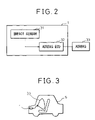
- FIG. 2 is a circuit diagram of an airbag control device to which the present invention is applied;
- FIG. 3 is a view of the state of the airbag control device of FIG. 2 mounted in a vehicle;
- FIG. 4 is an outside perspective view of an impact sensor device to which the present invention is applied;
- FIG. 5 is a view of the device of FIG. 4 as seen from above;
- FIG. 6 is a sectional view seen along the line A-A of FIG. 5 ;
- FIG. 7 is a view of the device of FIG. 4 as seen from the bottom;
- FIG. 8 is a view of the housing of the device of FIG. 4 in the state seen from the bottom at an angle;
- FIG. 9 is a view showing conceptually the structure of board mounting seats of an impact sensor device to which the present invention is applied.
- FIG. 10A and FIG. 10B are views for explaining the method of mounting a connector in the device of FIG. 4 .
- FIG. 2 is a circuit diagram of an airbag control device to which the present invention is applied
- FIG. 3 is a view of the state of the airbag control device of FIG. 2
- the impact sensor 31 detects this and outputs a detection signal to an airbag ECU 32 .
- the airbag ECU 32 judges the existence of collision based on the input signal. When it judges that collision has occurred, it issues an ignition signal for deploying the airbag 33 for protecting the passengers.
- the operation of the airbag ECU is known, so explanation of it here will be omitted.
- FIG. 4 is an outside perspective view of an impact sensor device to which the present invention is applied;
- FIG. 5 is a view of the device of FIG. 4 as seen from above;
- FIG. 6 is a sectional view seen along the line A-A of FIG. 5 ;
- FIG. 7 is a view of the device of FIG. 4 as seen from the bottom.
- the housing 2 of the airbag control system 1 is fabricated by plastic molding.
- the housing 2 is formed with an open bottom in structure.
- a circuit board 2 and a bottom cover 4 are mounted from the open bottom side.
- the circuit board 3 while not shown, mounts an impact sensor and an airbag ECU.
- Board mounting seats 7 and 8 for attaching the circuit board 3 and bottom cover 4 are provided inside the housing 2 . Details of the board mounting seats 7 and 8 will be given later.
- a connector 12 is attached in the opening 9 .
- the connector 12 is connected with an airbag ECU mounted on the circuit board 3 and is arranged connectably with the outside through the opening 9 .
- Mounting brackets 6 are formed at three points at the bottom of the housing 2 .
- the airbag control device 1 is fastened by screwing the mounting brackets 6 to a vehicle 5 .
- the impact caused at the vehicle 5 due to collision etc. is transmitted through the housing 2 to the circuit board 3 .
- the impact sensor mounted on the circuit board 3 detects this and outputs the detection signal to the airbag ECU.
- the airbag ECU judges the occurrence of impact based on the input signal. When judging that impact has occurred, it outputs an ignition signal for deploying the airbag for protecting the passenger.
- the operation of the airbag ECU is known, so the explanation will be omitted here.
- FIG. 8 is a view of the housing 2 as seen from below at an angle.
- the housing 2 has an opening 9 side used for the connector mount 13 and has a part deeper than the opening 9 used for a circuit board mount 14 .
- Struts 17 are formed at the circuit board mount 14 .
- the struts 17 will be explained later.
- One mounting bracket 6 is provided at the connector mount 13 side, and two are provided at the opposite side.
- the inside walls of the connector mount 13 are formed with grooves 15 for mounting the connector 12 .
- the method of mounting the connectors 12 utilizing the grooves 15 will be explained later.
- the inside of the circuit board mount 14 is formed with four board mounting seats 7 and 8 for mounting the circuit board 3 facing the bottom of the housing 2 .
- the circuit board 3 and the bottom cover 4 are mounted by screws 11 utilizing the screw holes formed at the front ends of the board mounting seats 7 and 8 .
- Two board mounting seats 7 provided at the connector mount 13 side are formed integrally with the side walls of the housing 2 and the connector mount 13 .
- the two board mounting seats 8 at the opposite side are provided at a space from the side wall of the housing 2 .
- the number of the board mounting seats 7 and the number of the board mounting seats 8 may be freely set.
- FIG. 9 will be used to explain the structure of the board mounting seats 7 and the board mounting seats 8 .
- FIG. 9 conceptually shows this for clarifying the difference between the board mounting seats 7 and the board mounting seats 8 .
- Each board mounting seat 7 is formed integrally with the connector mount 13 and the side wall of the housing 2 , while each board mounting seat 8 is formed at a space from the side wall of the housing 2 . Therefore, each board mounting seat 7 rigidly fixes the circuit board 3 to the housing 2 , while each board mounting seat 8 flexibly fixes the circuit board 3 to the housing 2 .
- the housing 2 sometimes deforms due to the mounting heights and the state of surface precision of the mounting brackets 6 , or the housing 2 sometimes deforms due to deformation of the vehicle 5 upon collision. If the housing 2 deforms, the mounting positions of the board mounting seats 7 and 8 move and force is applied deforming the circuit board 3 . Further, when impact is transmitted to the housing 2 , the wall of the housing 2 shakes. Due to this as well, the mounting positions of the board mounting seats 7 and 8 move and force is applied deforming the circuit board 3 .
- the efficiency of transmission of impact can be raised and the impact can be detected efficiently. Further, by making the remaining board mounting seats 8 flexible in structure with respect to the housing 2 , even if the housing 2 deforms, shake, etc., the deformation is not transmitted to the circuit board and destruction etc. of the circuit board can be prevented.
- FIG. 10 will be used to explain the method of mounting the connector 12 .
- the figure shows the connector mount 13 as seen from the bottom.
- any method may be applied, but below, two examples will be shown.
- the inside walls of the connector mount 13 are formed with grooves 15 for connector mounting.
- the two side faces of the connector 12 are formed with a pair of projections 21 for engaging with the grooves 15 of the housing 2 .
- the projections 21 are further formed with pairs of projections 22 projecting to the two sides.
- the lengths between the tips of the pairs of projections 22 are set larger than the widths of the grooves 15 .
- the projections 21 of the connector 12 engage with the grooves 15 from the bottom of the housing 2 and the connector 12 is pushed into the connector mount 13 .
- the pairs of projections 22 engage with the inside surfaces of the grooves 15 , whereby the connector 12 is held rigidly with the connector mount 13 .
- the inside surfaces of the connector mount 13 are formed with projections 23 .
- the two side faces of the connector 12 are formed with members 24 having grooves for insertion of the projections 23 .
- the connector 12 is mounted with the housing 2 in the state fixed and connected to the circuit board 3 .
- the circuit board 3 is positioned at the mounting positions of the board mounting seats 7 and 8 .
- the airbag control device 1 finishes being assembled.
- the connector 12 and the circuit board 3 may be mounted separately to the housing 2 . In this case, it is possible to first mount the connector 12 to the housing 2 and then mount the circuit board 3 or first mount the circuit board 3 to the housing 2 and then mount the connector 12 . In either case, means are devised for automatic connection of the circuit board 3 and connector 12 in the state of completion of mounting.
- the impact propagation path (arrow 16 ) from the mounting brackets 6 to the circuit board 3 explained in FIG. 7 is made further rigid in structure and the impact of the vehicle 5 can be transmitted to the impact sensor.
- the struts 17 provided at the housing 2 will be explained next.
- the connecting parts of the top part and sides of the housing 2 are formed with struts 17 .
- the struts 17 are formed in shapes with the connecting parts between the top and sides of the housing 2 bent inward.
- the struts 17 are formed between the board mounting seats 7 and the board mounting seats 8 and between the board mounting seats 8 .
- the pairs of board mounting seats 7 are made more rigid by mounting the connector 12 , so the struts are omitted.
- the structure of the struts 17 is not limited to the illustrated example and may be made any structure.
- the present invention is not limited to an airbag control device.
- the airbag ECU mounted on the circuit board and utilizing the invention as an impact sensor device for outputting an output signal of the impact sensor to the outside.
- the invention instead of the airbag ECU, it is possible to apply the invention to a control device of another application mounting a microcomputer for another application, detecting impact, and performing control.
- the invention to a vibration sensor device mounting a vibration sensor for detecting vibration or another device for detecting force from the outside applied to a vehicle or behavior of the vehicle etc.
Landscapes
- Engineering & Computer Science (AREA)
- Mechanical Engineering (AREA)
- Microelectronics & Electronic Packaging (AREA)
- Air Bags (AREA)
- Connection Of Plates (AREA)
Applications Claiming Priority (2)
| Application Number | Priority Date | Filing Date | Title |
|---|---|---|---|
| JP2003397210A JP2005155827A (ja) | 2003-11-27 | 2003-11-27 | 固定構造 |
| JP2003-397210 | 2003-11-27 |
Publications (2)
| Publication Number | Publication Date |
|---|---|
| US20050118843A1 US20050118843A1 (en) | 2005-06-02 |
| US7510404B2 true US7510404B2 (en) | 2009-03-31 |
Family
ID=34616522
Family Applications (1)
| Application Number | Title | Priority Date | Filing Date |
|---|---|---|---|
| US10/997,668 Expired - Fee Related US7510404B2 (en) | 2003-11-27 | 2004-11-24 | Fixing structure and control device using that fixing structure |
Country Status (3)
| Country | Link |
|---|---|
| US (1) | US7510404B2 (enExample) |
| JP (1) | JP2005155827A (enExample) |
| CN (1) | CN100377923C (enExample) |
Cited By (13)
| Publication number | Priority date | Publication date | Assignee | Title |
|---|---|---|---|---|
| US20090086448A1 (en) * | 2007-09-27 | 2009-04-02 | Hiew Siew S | Solid state drive with coverless casing |
| US20100182757A1 (en) * | 2009-01-20 | 2010-07-22 | Denso Corporation | Housing for in-vehicle electronic control unit |
| US20100253188A1 (en) * | 2009-04-03 | 2010-10-07 | Fujitsu Ten Limited | Housing structure for in-vehicle electronic device |
| US20120026703A1 (en) * | 2010-07-27 | 2012-02-02 | Denso Corporation | In-vehicle electronic control unit housing |
| US20120174669A1 (en) * | 2011-01-11 | 2012-07-12 | Delphi Technologies, Inc. | Collision sensor housing and module |
| US20120258635A1 (en) * | 2011-04-05 | 2012-10-11 | Sumitomo Wiring Systems, Ltd. | Vehicle-side connector |
| US8899370B1 (en) * | 2013-05-31 | 2014-12-02 | Honda Motor Co., Ltd. | Casing for housing occupant protection device control unit |
| US20170210307A1 (en) * | 2016-01-22 | 2017-07-27 | Toyota Motor Engineering & Manufacturing North America, Inc. | Attachment for electrical components |
| US9776586B2 (en) | 2015-12-09 | 2017-10-03 | Toyota Motor Engineering & Manufacturing North America, Inc. | Deformable attachment for electrical components |
| US10144360B2 (en) | 2016-05-19 | 2018-12-04 | Ford Global Technologies, Llc | Restraints control module attachment assembly |
| US10150440B2 (en) * | 2016-05-19 | 2018-12-11 | Ford Global Technologies, Llc | Restraints control module attachment assembly |
| US10340626B2 (en) * | 2016-02-18 | 2019-07-02 | Sumitomo Wiring Systems, Ltd. | Connector mounting structure |
| US11312233B2 (en) * | 2018-08-21 | 2022-04-26 | Toyota Jidosha Kabushiki Kaisha | Shift bracket |
Families Citing this family (8)
| Publication number | Priority date | Publication date | Assignee | Title |
|---|---|---|---|---|
| JP4458123B2 (ja) * | 2007-07-10 | 2010-04-28 | 住友電装株式会社 | 自動車用の電気接続箱 |
| BRPI0916519B1 (pt) * | 2008-07-28 | 2019-07-16 | Trw Automotive U.S. Llc | Conjunto sensor de colisão, e, método para montar um sensor de colisão |
| JP5184286B2 (ja) | 2008-09-30 | 2013-04-17 | 富士通テン株式会社 | 筐体固定構造 |
| CN102356012B (zh) * | 2009-03-19 | 2015-04-22 | 奥托立夫开发公司 | 驾乘员束缚装置控制装置 |
| JP5958761B2 (ja) * | 2012-11-30 | 2016-08-02 | 株式会社デンソー | 車両用電子制御ユニット |
| WO2016147393A1 (ja) * | 2015-03-19 | 2016-09-22 | 能美防災株式会社 | センサユニット |
| US20180263136A1 (en) * | 2017-03-11 | 2018-09-13 | Microsoft Technology Licensing, Llc | Flexible or rotatable connectors in electronic devices |
| CN112822886B (zh) * | 2020-12-30 | 2022-05-27 | 重庆凯歌电子股份有限公司 | 一种车载pcb电路板 |
Citations (12)
| Publication number | Priority date | Publication date | Assignee | Title |
|---|---|---|---|---|
| US3668476A (en) * | 1970-09-11 | 1972-06-06 | Seeburg Corp | Self-locking enclosure for electronic circuitry and method of assembling the same |
| US4392701A (en) * | 1980-07-16 | 1983-07-12 | Amp Incorporated | Tap connector assembly |
| JPH05329A (ja) | 1991-06-24 | 1993-01-08 | Matsushita Electric Works Ltd | 曲げ加工方法 |
| US5411401A (en) * | 1993-12-31 | 1995-05-02 | Silitek Corporation | Structure of electrical connector |
| CN2229385Y (zh) | 1995-09-15 | 1996-06-19 | 北京市赫达汽车安全技术公司 | 汽车安全气囊的电子控制装置专用控制器 |
| US5761046A (en) * | 1994-12-17 | 1998-06-02 | Wabco Vermogensverwaltungs-Gmbh | Sealed housing for an electrical component |
| CN2348503Y (zh) | 1998-11-25 | 1999-11-10 | 富士康(昆山)电脑接插件有限公司 | 电连接器 |
| US6042392A (en) * | 1996-10-28 | 2000-03-28 | Yazaki Corporation | Printed circuit board connector fitting structure |
| JP2000315877A (ja) | 1999-04-28 | 2000-11-14 | Matsushita Electric Ind Co Ltd | プリント基板固定装置 |
| US6431884B1 (en) * | 2001-01-23 | 2002-08-13 | Trw Inc. | Apparatus and method for shielding a circuit from electromagnetic interference |
| JP2002308021A (ja) | 2001-04-12 | 2002-10-23 | Fujitsu Ten Ltd | 車載用電子機器 |
| US6709291B1 (en) * | 2000-06-22 | 2004-03-23 | Trw Inc. | Apparatus and method for shielding a circuit from electromagnetic interference |
Family Cites Families (9)
| Publication number | Priority date | Publication date | Assignee | Title |
|---|---|---|---|---|
| JPH05329U (ja) * | 1991-06-25 | 1993-01-08 | 松下電工株式会社 | ケースの取付構造 |
| JPH05172624A (ja) * | 1991-12-25 | 1993-07-09 | Fujikura Ltd | 圧電型振動センサ装置 |
| JPH0820306A (ja) * | 1994-07-08 | 1996-01-23 | Nissan Shatai Co Ltd | エアバッグセンサへの衝撃伝達構造 |
| JP3201242B2 (ja) * | 1995-12-06 | 2001-08-20 | トヨタ自動車株式会社 | センサ組立体及びその組み立て方法 |
| JPH09207706A (ja) * | 1996-02-01 | 1997-08-12 | Hitachi Ltd | 衝突検知装置 |
| JPH09331180A (ja) * | 1996-06-12 | 1997-12-22 | Nec Corp | 電子機器筐体構造 |
| JP3795607B2 (ja) * | 1997-01-08 | 2006-07-12 | 株式会社ケーヒン | 封止形筐体 |
| FR2801124B1 (fr) * | 1999-11-15 | 2002-02-08 | Neopost Ind | Module de comptabilisation securise pour machine a affranchir |
| JP2002016370A (ja) * | 2000-04-28 | 2002-01-18 | Hosiden Corp | 小型携帯機器用ケース |
-
2003
- 2003-11-27 JP JP2003397210A patent/JP2005155827A/ja active Pending
-
2004
- 2004-11-24 US US10/997,668 patent/US7510404B2/en not_active Expired - Fee Related
- 2004-11-26 CN CNB2004100961344A patent/CN100377923C/zh not_active Expired - Fee Related
Patent Citations (12)
| Publication number | Priority date | Publication date | Assignee | Title |
|---|---|---|---|---|
| US3668476A (en) * | 1970-09-11 | 1972-06-06 | Seeburg Corp | Self-locking enclosure for electronic circuitry and method of assembling the same |
| US4392701A (en) * | 1980-07-16 | 1983-07-12 | Amp Incorporated | Tap connector assembly |
| JPH05329A (ja) | 1991-06-24 | 1993-01-08 | Matsushita Electric Works Ltd | 曲げ加工方法 |
| US5411401A (en) * | 1993-12-31 | 1995-05-02 | Silitek Corporation | Structure of electrical connector |
| US5761046A (en) * | 1994-12-17 | 1998-06-02 | Wabco Vermogensverwaltungs-Gmbh | Sealed housing for an electrical component |
| CN2229385Y (zh) | 1995-09-15 | 1996-06-19 | 北京市赫达汽车安全技术公司 | 汽车安全气囊的电子控制装置专用控制器 |
| US6042392A (en) * | 1996-10-28 | 2000-03-28 | Yazaki Corporation | Printed circuit board connector fitting structure |
| CN2348503Y (zh) | 1998-11-25 | 1999-11-10 | 富士康(昆山)电脑接插件有限公司 | 电连接器 |
| JP2000315877A (ja) | 1999-04-28 | 2000-11-14 | Matsushita Electric Ind Co Ltd | プリント基板固定装置 |
| US6709291B1 (en) * | 2000-06-22 | 2004-03-23 | Trw Inc. | Apparatus and method for shielding a circuit from electromagnetic interference |
| US6431884B1 (en) * | 2001-01-23 | 2002-08-13 | Trw Inc. | Apparatus and method for shielding a circuit from electromagnetic interference |
| JP2002308021A (ja) | 2001-04-12 | 2002-10-23 | Fujitsu Ten Ltd | 車載用電子機器 |
Cited By (19)
| Publication number | Priority date | Publication date | Assignee | Title |
|---|---|---|---|---|
| US20090086448A1 (en) * | 2007-09-27 | 2009-04-02 | Hiew Siew S | Solid state drive with coverless casing |
| US8144476B2 (en) * | 2009-01-20 | 2012-03-27 | Denso Corporation | Housing for in-vehicle electronic control unit |
| US20100182757A1 (en) * | 2009-01-20 | 2010-07-22 | Denso Corporation | Housing for in-vehicle electronic control unit |
| US8414013B2 (en) * | 2009-04-03 | 2013-04-09 | Fujitsu Ten Limited | Housing structure for in-vehicle electronic device |
| US20100253188A1 (en) * | 2009-04-03 | 2010-10-07 | Fujitsu Ten Limited | Housing structure for in-vehicle electronic device |
| US20120026703A1 (en) * | 2010-07-27 | 2012-02-02 | Denso Corporation | In-vehicle electronic control unit housing |
| US8830686B2 (en) * | 2010-07-27 | 2014-09-09 | Denso Corporation | In-vehicle electronic control unit housing |
| US8387457B2 (en) * | 2011-01-11 | 2013-03-05 | Delphi Technologies, Inc. | Collision sensor housing and module |
| US20120174669A1 (en) * | 2011-01-11 | 2012-07-12 | Delphi Technologies, Inc. | Collision sensor housing and module |
| US20120258635A1 (en) * | 2011-04-05 | 2012-10-11 | Sumitomo Wiring Systems, Ltd. | Vehicle-side connector |
| US8740632B2 (en) * | 2011-04-05 | 2014-06-03 | Sumitomo Wiring Systems, Ltd. | Vehicle-side connector |
| US8899370B1 (en) * | 2013-05-31 | 2014-12-02 | Honda Motor Co., Ltd. | Casing for housing occupant protection device control unit |
| US20140354123A1 (en) * | 2013-05-31 | 2014-12-04 | Honda Motor Co., Ltd. | Casing for housing occupant protection device control unit |
| US9776586B2 (en) | 2015-12-09 | 2017-10-03 | Toyota Motor Engineering & Manufacturing North America, Inc. | Deformable attachment for electrical components |
| US20170210307A1 (en) * | 2016-01-22 | 2017-07-27 | Toyota Motor Engineering & Manufacturing North America, Inc. | Attachment for electrical components |
| US10340626B2 (en) * | 2016-02-18 | 2019-07-02 | Sumitomo Wiring Systems, Ltd. | Connector mounting structure |
| US10144360B2 (en) | 2016-05-19 | 2018-12-04 | Ford Global Technologies, Llc | Restraints control module attachment assembly |
| US10150440B2 (en) * | 2016-05-19 | 2018-12-11 | Ford Global Technologies, Llc | Restraints control module attachment assembly |
| US11312233B2 (en) * | 2018-08-21 | 2022-04-26 | Toyota Jidosha Kabushiki Kaisha | Shift bracket |
Also Published As
| Publication number | Publication date |
|---|---|
| CN1621282A (zh) | 2005-06-01 |
| US20050118843A1 (en) | 2005-06-02 |
| JP2005155827A (ja) | 2005-06-16 |
| CN100377923C (zh) | 2008-04-02 |
Similar Documents
| Publication | Publication Date | Title |
|---|---|---|
| US7510404B2 (en) | Fixing structure and control device using that fixing structure | |
| US8414013B2 (en) | Housing structure for in-vehicle electronic device | |
| US20020149918A1 (en) | Vehicular electronic device | |
| JP5184286B2 (ja) | 筐体固定構造 | |
| US10039200B2 (en) | Engagement structure, electronic component module, and electrical connection box | |
| EP3541154B1 (en) | Passenger protection control device | |
| JP2012001105A (ja) | 車載用電子制御ユニット装置 | |
| US7654864B2 (en) | Mounting bracket structure | |
| KR20210002337A (ko) | 전기 장비의 nvh 문제를 감소 또는 제거하도록 구성된 모듈 및 전기 장비 | |
| CN112803180B (zh) | 逆变器装置 | |
| JP2010215127A (ja) | 車載用電子機器 | |
| KR20010101809A (ko) | 에어백 센서 모듈 설치 장치 및 방법 | |
| US11201421B2 (en) | Printed circuit board mounting arrangement | |
| JP5477786B2 (ja) | 車載用制御装置 | |
| JP3675243B2 (ja) | 電子制御機器 | |
| CN113690527B (zh) | 容器和可安装部件的组合体以及容器 | |
| JP7636384B2 (ja) | 電子機器 | |
| JP4830850B2 (ja) | 基板取付器 | |
| JP2021018168A (ja) | 電子装置 | |
| CN120294757A (zh) | 雷达装置及雷达装置的支承构造 | |
| WO2025062608A1 (ja) | 電子装置 | |
| CN120642199A (zh) | 电力转换装置 | |
| JP2002232166A (ja) | 回路基板の収容ケース | |
| JP2014092367A (ja) | 電子装置 | |
| JP2020185806A (ja) | エンジンコントロールモジュール用カバーおよびエンジンコントロールモジュール用カバーの取付構造 |
Legal Events
| Date | Code | Title | Description |
|---|---|---|---|
| AS | Assignment |
Owner name: FUJITSU TEN LIMITED, JAPAN Free format text: ASSIGNMENT OF ASSIGNORS INTEREST;ASSIGNOR:KOYAMA, TAKESHI;REEL/FRAME:016023/0477 Effective date: 20041111 |
|
| FEPP | Fee payment procedure |
Free format text: PAYOR NUMBER ASSIGNED (ORIGINAL EVENT CODE: ASPN); ENTITY STATUS OF PATENT OWNER: LARGE ENTITY |
|
| REMI | Maintenance fee reminder mailed | ||
| LAPS | Lapse for failure to pay maintenance fees | ||
| STCH | Information on status: patent discontinuation |
Free format text: PATENT EXPIRED DUE TO NONPAYMENT OF MAINTENANCE FEES UNDER 37 CFR 1.362 |
|
| FP | Lapsed due to failure to pay maintenance fee |
Effective date: 20130331 |