US6727963B1 - Liquid crystal display - Google Patents
Liquid crystal display Download PDFInfo
- Publication number
- US6727963B1 US6727963B1 US09/463,776 US46377600A US6727963B1 US 6727963 B1 US6727963 B1 US 6727963B1 US 46377600 A US46377600 A US 46377600A US 6727963 B1 US6727963 B1 US 6727963B1
- Authority
- US
- United States
- Prior art keywords
- light
- conductor plate
- angle
- liquid crystal
- light conductor
- Prior art date
- Legal status (The legal status is an assumption and is not a legal conclusion. Google has not performed a legal analysis and makes no representation as to the accuracy of the status listed.)
- Expired - Lifetime
Links
Images


Classifications
-
- G—PHYSICS
- G02—OPTICS
- G02F—OPTICAL DEVICES OR ARRANGEMENTS FOR THE CONTROL OF LIGHT BY MODIFICATION OF THE OPTICAL PROPERTIES OF THE MEDIA OF THE ELEMENTS INVOLVED THEREIN; NON-LINEAR OPTICS; FREQUENCY-CHANGING OF LIGHT; OPTICAL LOGIC ELEMENTS; OPTICAL ANALOGUE/DIGITAL CONVERTERS
- G02F1/00—Devices or arrangements for the control of the intensity, colour, phase, polarisation or direction of light arriving from an independent light source, e.g. switching, gating or modulating; Non-linear optics
- G02F1/01—Devices or arrangements for the control of the intensity, colour, phase, polarisation or direction of light arriving from an independent light source, e.g. switching, gating or modulating; Non-linear optics for the control of the intensity, phase, polarisation or colour
- G02F1/13—Devices or arrangements for the control of the intensity, colour, phase, polarisation or direction of light arriving from an independent light source, e.g. switching, gating or modulating; Non-linear optics for the control of the intensity, phase, polarisation or colour based on liquid crystals, e.g. single liquid crystal display cells
- G02F1/133—Constructional arrangements; Operation of liquid crystal cells; Circuit arrangements
- G02F1/1333—Constructional arrangements; Manufacturing methods
- G02F1/1335—Structural association of cells with optical devices, e.g. polarisers or reflectors
-
- G—PHYSICS
- G02—OPTICS
- G02B—OPTICAL ELEMENTS, SYSTEMS OR APPARATUS
- G02B6/00—Light guides; Structural details of arrangements comprising light guides and other optical elements, e.g. couplings
- G02B6/0001—Light guides; Structural details of arrangements comprising light guides and other optical elements, e.g. couplings specially adapted for lighting devices or systems
- G02B6/0011—Light guides; Structural details of arrangements comprising light guides and other optical elements, e.g. couplings specially adapted for lighting devices or systems the light guides being planar or of plate-like form
- G02B6/0033—Means for improving the coupling-out of light from the light guide
- G02B6/0035—Means for improving the coupling-out of light from the light guide provided on the surface of the light guide or in the bulk of it
- G02B6/0036—2-D arrangement of prisms, protrusions, indentations or roughened surfaces
-
- G—PHYSICS
- G02—OPTICS
- G02B—OPTICAL ELEMENTS, SYSTEMS OR APPARATUS
- G02B6/00—Light guides; Structural details of arrangements comprising light guides and other optical elements, e.g. couplings
- G02B6/0001—Light guides; Structural details of arrangements comprising light guides and other optical elements, e.g. couplings specially adapted for lighting devices or systems
- G02B6/0011—Light guides; Structural details of arrangements comprising light guides and other optical elements, e.g. couplings specially adapted for lighting devices or systems the light guides being planar or of plate-like form
- G02B6/0033—Means for improving the coupling-out of light from the light guide
- G02B6/0058—Means for improving the coupling-out of light from the light guide varying in density, size, shape or depth along the light guide
- G02B6/0061—Means for improving the coupling-out of light from the light guide varying in density, size, shape or depth along the light guide to provide homogeneous light output intensity
-
- G—PHYSICS
- G02—OPTICS
- G02F—OPTICAL DEVICES OR ARRANGEMENTS FOR THE CONTROL OF LIGHT BY MODIFICATION OF THE OPTICAL PROPERTIES OF THE MEDIA OF THE ELEMENTS INVOLVED THEREIN; NON-LINEAR OPTICS; FREQUENCY-CHANGING OF LIGHT; OPTICAL LOGIC ELEMENTS; OPTICAL ANALOGUE/DIGITAL CONVERTERS
- G02F1/00—Devices or arrangements for the control of the intensity, colour, phase, polarisation or direction of light arriving from an independent light source, e.g. switching, gating or modulating; Non-linear optics
- G02F1/01—Devices or arrangements for the control of the intensity, colour, phase, polarisation or direction of light arriving from an independent light source, e.g. switching, gating or modulating; Non-linear optics for the control of the intensity, phase, polarisation or colour
- G02F1/13—Devices or arrangements for the control of the intensity, colour, phase, polarisation or direction of light arriving from an independent light source, e.g. switching, gating or modulating; Non-linear optics for the control of the intensity, phase, polarisation or colour based on liquid crystals, e.g. single liquid crystal display cells
- G02F1/133—Constructional arrangements; Operation of liquid crystal cells; Circuit arrangements
- G02F1/1333—Constructional arrangements; Manufacturing methods
- G02F1/1335—Structural association of cells with optical devices, e.g. polarisers or reflectors
- G02F1/1336—Illuminating devices
- G02F1/133615—Edge-illuminating devices, i.e. illuminating from the side
Definitions
- the present invention relates to a back light type liquid crystal apparatus.
- a liquid crystal apparatus is generally employed for a display apparatus thereof, however, in accordance with a development to a color display in recent years, a back light type display apparatus in which a light source is arranged at the back of a liquid crystal display plate and a whole of a display surface is lighted up from a back side spread. It is necessary to make a brightness of the light source as the back light apparatus for this kind of display apparatus high, and light up the whole of the flat surface without unevenness of the brightness.
- an improved brightness can be easily achieved by increasing the brightness of the light source, however, an increase of the brightness of the light source is limited because a battery or the like is employed as a drive source in the lap-top type personal computer and the like, so that there has been conventionally no effective method.
- a lamp such as a cold-cathode tube, a hot-cathode tube or the like is employed for a light source 1 , this is arranged on an end surface of a light conductor plate 2 made of a permeable material, a light scattering layer 3 for scattering a light and a reflecting plate 4 for reflecting a light is provided one a lower surface of the light conductor plate 2 , and a diffusion plate 5 made of a milk white synthetic resin having an optical confusion effect for making a brightness of the light surface uniform all around the whole surface is provided on an upper surface of the light conductor plate 2 . Further, on an upper surface thereof, there are arranged a first light condensing plate 6 and a second light condensing plate 7 which converge a diffused light at a certain degree so as to improve
- FIG. 3 shows a structure of the light confusion layer.
- the light confusion layer is structured such that a plurality of light confusion materials 8 using a titanium oxide or the like is formed on the surface of the light conductor plate 2 in accordance with a method such as a printing or the like.
- An optical strength from the light source becomes lowered as being apart from the light source 1 . Accordingly, an area of the light confusion materials is set to become larger as they are apart from the light source.
- the conventional light apparatus it is structured such that an emitting light from the light source is introduced to the light conductor plate, confused by the light confusion materials contained in the light confusion layer and thereafter irradiated to a liquid crystal element after passing through the diffusion plate, so that the structure is complex and there is a problem that the brightness is lowered due to a loss such as the light confusion and the like. Further, there is a problem that in the method of forming the grating groove, it is hard to manufacture a metal mold.
- the present invention is made for solving the current status mentioned above, and an object of the present invention is to provide a liquid crystal apparatus which improves the conventional disadvantages and can improve a brightness without increasing a brightness of the light source.
- a light conductor plate having a plurality of small projecting portions or small recess portions (hereinafter, refer to as dots) with a suitably controlled angle of incline of a cross section is employed for converting a direction of a forward movement of a waveguide light within a light conductor plate into a predetermined direction.
- a reflection film is formed along the dots or the reflection film is arranged as occasion demands.
- a prism sheet having a suitable prism top angle is arranged as occasion demands, thereby irradiating a light beam having a suitable angle distribution toward a display element from a light outputting surface.
- a member in which an arrangement of the dots satisfies a fixed restricting condition and the dots are arranged and formed at random is employed. Further, by changing a number of the dots and/or a shape thereof and/or a size thereof as occasion demands, an angle distribution of the emitting light is made uniform and an unevenness of the brightness is prevented from being generated.
- FIG. 1 is a perspective view of a back light apparatus portion of a liquid crystal display apparatus in accordance with the present invention
- FIG. 2 is a cross sectional view of a conventional dot printing type light conductor plate
- FIG. 3 is a schematic view of a dot printing in FIG. 2;
- FIG. 4 is a schematic view of a size of the dot in accordance with the present invention.
- FIG. 5 is a view which totally shows an embodiment in accordance with the present invention.
- FIG. 6 is a schematic view of a direction of cutting an angle of incline of a cross section in accordance with the present invention.
- FIG. 7 is a first schematic view of the angle of incline of a cross section in accordance with the present invention.
- FIG. 8 is a second schematic view of the angle of incline of a cross section in accordance with the present invention.
- FIG. 9 is a third schematic view of the angle of incline of a cross section in accordance with the present invention.
- FIG. 10 is a fourth schematic view of the angle of incline of a cross section in accordance with the present invention.
- FIG. 11 is a fifth schematic view of the angle of incline of a cross section in accordance with the present invention.
- FIG. 12 is a sixth schematic view of the angle of incline of a cross section in accordance with the present invention.
- FIG. 13 is a seventh schematic view of the angle of incline of a cross section in accordance with the present invention.
- FIG. 14 is a eighth schematic view of the angle of incline of a cross section in accordance with the present invention.
- FIG. 15 is a ninth schematic view of the angle of incline of a cross section in accordance with the present invention.
- FIG. 16 is a tenth schematic view of the angle of incline of a cross section in accordance with the present invention.
- FIG. 17 is a view which totally shows a shape of a flat surface of the dot in accordance with the present invention.
- FIG. 18 is a perspective view which shows a small recess portion of a light conductor plate in accordance with the present invention.
- FIG. 19 is a schematic view of a shape of the small recess portion of the light conductor plate in accordance with the present invention.
- FIG. 20 is a view for explaining a locus of a light beam within the light conductor plate in accordance with a first embodiment of the present invention
- FIG. 21 is a schematic view of a shape of the light conductor plate in accordance with the present invention.
- FIG. 22 is a first view of a relation between an angle of incline of a cross section of the small recess portion and an angle distribution of the emitting light in accordance with the first embodiment of the present invention
- FIG. 23 is a first view of a relation between an angle of incline of a cross section of the small recess portion and a strength of the emitting light in accordance with the first embodiment of the present invention
- FIG. 24 is a second view of a relation between an angle of incline of a cross section of the small recess portion and an angle distribution of the emitting light in accordance with the first embodiment of the present invention
- FIG. 25 is a second view of a relation between an angle of incline of a cross section of the small recess portion and a strength of the emitting light in accordance with the first embodiment of the present invention
- FIG. 26 is a third view of a relation between an angle of incline of a cross section of the small recess portion and an angle distribution of the emitting light in accordance with the first embodiment of the present invention
- FIG. 27 is a third view of a relation between an angle of incline of a cross section of the small recess portion and a strength of the emitting light in accordance with the first embodiment of the present invention
- FIG. 28 is a view which totally shows a shape of a flat surface of the dot in accordance with the present invention.
- FIG. 29 is a view of a cross sectional shape of the small recess portion in accordance with the present invention.
- FIG. 30 is a view of a relation between a depth of the small recess portion and a strength of the emitting light in accordance with the present invention.
- FIG. 31 is a view of a relation between a size of the small recess portion and a visibility of the dot in accordance with the present invention.
- FIG. 32 is a schematic view of a structure in accordance with the present invention.
- FIG. 33 is a perspective view of a back light apparatus portion in accordance with a second embodiment of a liquid crystal display apparatus of the present invention.
- FIG. 34 is a perspective view which shows a small projecting portion of the light conductor plate in accordance with the present invention.
- FIG. 35 is a schematic view of a shape of a small projecting portion of the light conductor plate in accordance with the present invention.
- FIG. 36 is a view for explaining a locus of a light beam within the light conductor plate in accordance with the present invention.
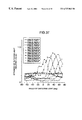
- FIG. 37 is a view of a relation between an angle of incline of a cross section of the small projecting portion and an angle distribution of the emitting light in accordance with the second embodiment of the present invention.
- FIG. 38 is a view of a relation between an angle of incline of a cross section of the small projecting portion and a strength of the emitting light in accordance with the second embodiment of the present invention.
- FIG. 39 is a view of a cross sectional shape of the small projecting portion in accordance with the present invention.
- FIG. 40 is a view of a relation between a depth of the small projecting portion and a strength of the emitting light in accordance with the present invention.
- FIG. 41 is a perspective view of a back light apparatus portion in accordance with a third embodiment of a liquid crystal display apparatus of the present invention.
- FIG. 42 is a perspective view which shows a small recess portion of the light conductor plate in accordance with the present invention.
- FIG. 43 is a view for explaining a locus of a light beam within the light conductor plate in accordance with the third embodiment of the present invention.
- FIG. 44 is a schematic view of an angle distribution of the emitting light in accordance with the third embodiment of the present invention.
- FIG. 45 is a view of a relation between an angle of incline of a cross section of the small recess portion and a strength of the emitting light in accordance with the third embodiment of the present invention.
- FIG. 46 is a view of a cross sectional shape of a light condensing plate used for the present invention.
- FIG. 47 is a view of a main portion of a fourth embodiment of a liquid crystal display apparatus in accordance with the present invention.
- FIG. 48 is a first angle distribution of an emitting light of the fourth embodiment in accordance with the present invention.
- FIG. 49 is a second angle distribution of the emitting light of the fourth embodiment in accordance with the present invention.
- FIG. 50 is an angle dependence of the emitting light of the fourth embodiment in accordance with the present invention.
- FIG. 51 is a schematic view of FIG. 50.
- FIG. 52 is a view of an angle dependence of the emitting light at a time when an angle of incline of a cross section in accordance with the present invention is uniform;
- FIG. 53 is a view of an angle dependence of the emitting light in the case of changing an angle of incline of a cross section in accordance with the present invention.
- FIG. 54 is a view of an angle dependence of the emitting light in the case of locally changing an angle of incline of a cross section in accordance with the present invention.
- FIG. 55 is a view which shows a relation between a surface roughness and a brightness of a front surface in accordance with the present invention.
- FIG. 56 is a first view of a process for manufacturing the light conductor plate used for the present invention.
- FIG. 57 is a second view of a process for manufacturing the light conductor plate used for the present invention.
- FIG. 58 is a third view of a process for manufacturing the light conductor plate used for the present invention.
- FIG. 59 is a schematic view of a relation between a dot width and an angle of incline of a cross section in accordance with the present invention.
- FIG. 60 is a schematic view of a relation between an average distance between dots and an angle of incline of a cross section in accordance with the present invention.
- FIG. 61 is a schematic view of an example of a relation between a dot width and an angle of incline of a cross section in accordance with the present invention.
- FIG. 62 is an exploded perspective view of a main portion of a liquid crystal display apparatus in accordance with the present invention.
- a dot 9 constituted by a plurality of small projecting portions or small recess portions is formed on a surface of the light conductor plate.
- the dot corresponds, as shown in FIG.
- FIG. 5 totally shows an embodiment in accordance with the present invention, and shows an angle of an inclined surface of the small projecting portion or the small recess portion with respect to the flat portion of the surface of the light conductor plate (hereinafter, refer to as an angle of incline of a cross section), a distribution of angles of incline in a cross section, a depth or a height, a distribution thereof, a shape of a flat surface, a distribution of a shape, a size, an arrangement of dots, a distribution of density of dots, a distribution of shapes of the dots, and a sub material of the light conductor plate in accordance with the present invention.
- an angle of incline of a cross section a distribution of angles of incline in a cross section
- a depth or a height a distribution thereof
- a shape of a flat surface a distribution of a shape
- a size an arrangement of dots
- a distribution of density of dots a distribution of shapes of the dots
- An angle of incline of a cross section of the light conductor plate of the liquid crystal display apparatus in accordance with the present invention suitably has an angle of 7 to 85 degrees (preferably 7 to 43 degrees and 50 to 85 degrees).
- it is suitably set to 20 to 40 degrees
- in the case of employing a light condensing plate and not forming the reflecting film it is suitably set to 7 to 43 degrees
- in the case of not employing the light condensing plate and not forming the reflecting plate it is suitably set to 50 to 85 degrees.
- FIG. 6 is a view which explains a cutting surface 13 of the light conductor plate at a time of determining the angle of incline of the cross section.
- the angle of incline of the cross section is determined as shown in FIG. 7 .
- the cross sectional shape is at first approximated to a straight line.
- ⁇ 2 is set to be as the angle of incline of the cross section.
- an average value between ⁇ 1 and ⁇ 2 is set to be the angle of incline of the cross section.
- an average value between ⁇ 1 and ⁇ 2 is set to be the angle of incline of the cross section.
- a value ⁇ 1 ⁇ 2 is set to be the angle of incline of the cross section.
- an average value between ⁇ 1 and ⁇ 2 is set to be the angle of incline of the cross section.
- a value ⁇ 1 ⁇ 2 is set to be the angle of incline of the cross section. In this case, in the case that a relation ⁇ 2 ⁇ 10 degrees is established, a value ⁇ 1 ⁇ 2 is set to be the angle of incline of the cross section. In this case, in FIGS.
- the angle of incline of the cross section may be calculated in accordance with the following formula (formula 1). Further, it is desirable to approximate so that an approximate error (a difference between a true value and an approximate value) becomes 5% or less of a dot depth (a dot height) of the dot for calculating the angle of incline of the cross section. Further, a value of ⁇ corresponds to a value determined in accordance with a refractive index of the light conductor plate, and in the case that the refractive index is 1.47 ⁇ 0.1, about 18 degrees is suitable.
- L 1 LENGTH OF STRAIGHT LINE 1
- a cross sectional shape is approximated by the straight lines as little as possible so that the approximate error (the difference between the true value and the approximate value) becomes 5% or less of the dot depth (the dot height) of the dot for calculating the angle of incline of the cross section as shown in FIG. 16, and the angle of incline of the cross section is calculated by applying to the following formula (the formula 2) with respect to the straight line having an angle equal to or more than 5 degrees formed with respect to the flat portion 11 of the surface of the light conductor plate which functions as the effective reflection and refraction surface among the straight lines.
- the dot shape is not symmetrical in right and left, it is desirable to set an angle of an inclined surface in which the waveguide light within the light conductor plate is more reflected to the angle of incline of the cross section.
- the angle of incline of the cross section calculated in the manner mentioned above is defined within the range mentioned above, because an amount of the light emitted from the oblique direction is restricted at an amount equal to or more than necessary so as to improve the brightness of the front surface as well as the distribution of the emitting angle of the light from the emitting surface of the light conductor plate is made suitable. Further, it is desirable that the angle of incline of the cross section of the dot is made smaller as it is near the cold-cathode tube in order to intend to make the distribution of the angle of the brightness uniform.
- the depth or the height of the dot is suitably set to 2 to 100 ⁇ m (preferably 5 to 40 ⁇ m). Because the brightness of the portion near the light source becomes too high and as a result the distribution of the brightness becomes uneven in the case that the depth or the height of the dot is more than 100 ⁇ m, it is hard to charge the plastic material to the small projecting portion or the small recess portion of the dot and the desired dot shape can not be formed when forming the light conductor plate, and the size of the dot is increased so as to make the dot visible when setting the depth or the height of the dot to be greater.
- the depth or the height of the dot is smaller than 2 ⁇ m, a reflection efficiency of the light is lowered and it is impossible to obtain the desired brightness, and the waveguide light is easily confused and diffracted and it becomes the same in the case of simply setting the light conductor plate to the rough surface. Further, it is desirable to make the depth and the height of the dot smaller as it becomes near the cold-cathode tube in order to intend the uniformity of the distribution of the brightness.
- the shape of the flat surface of the dot that is, the shape in the case of viewing the dot from the front surface of the dot forming surface
- various shapes are effective and the shape is not particularly limited.
- the substantially rectangular shape has less confusion and is suitable for improving the brightness of the front surface, and since the others are effective for preventing a shadow from generating from the light inputting surface since a component of the confusion is great.
- the substantially rectangular shape includes a rectangular shape and means a shape obtained by providing a round at corners of the rectangle and a shape similar to the trapezoidal shape obtained by deforming a length of a line with respect to the rectangle.
- the distribution of the flat surface shape of the dot is structured such as to make the dot area smaller as it becomes near the cold-cathode tube in order to intend to make the distribution of the brightness uniform. Further, in the case that the confusion is particularly necessary, it is desirable to make the dot area partly small, or in the case that the dot shape is the substantially rectangular shape, it is desirable to set the shape to the substantially regular square or the circular shape.
- the size of the dot is desirably set such that the area thereof is 0.2 square mm or less (preferably 0.05 square mm or less). Further, in the case that the flat surface shape of the dot is the substantially rectangular shape, it is desirable that the length of the short line is 200 ⁇ m or less (preferably 100 ⁇ m or less). Because when the size of the dot becomes greater than this, the shape of the dot formed on the light conductor plate is visible (dot visible) in some characters or patterns in the case that the user for the personal computer or the like sees the liquid crystal display apparatus, thereby preventing a judgement of the characters and the patterns. On the contrary, the area of the dot is desirably greater than 0.000025 square mm (preferably 0.0001 square mm).
- An arrangement of the flat surface of the dot is desirably random. Because the dot in accordance with the present invention is fine, thereby preventing Moire generated by an interference with a regular pattern of the other members constituting the liquid crystal display apparatus, for example, a liquid crystal cell, a collar filter, a TFT pattern, a black stripe and the like.
- a regular pattern of the other members constituting the liquid crystal display apparatus for example, a liquid crystal cell, a collar filter, a TFT pattern, a black stripe and the like.
- the shape of the flat surface of the dot is the substantially rectangular shape, it is better to arrange the pattern so that a longer line of the rectangle is substantially in parallel to the emitting surface of the light source. Because it is easy to intend to make the distribution of the emitting angle proper.
- the density of the dot is desirably set smaller as the dot is closer to the light source in order to make the distribution of the brightness uniform.
- liquid crystal display apparatus in accordance with the present invention, it is effective for improving the brightness, making the distribution of the brightness proper and making the emitting angle proper to commonly employ the conventionally used sub materials such as the reflection plate, the diffusion plate, the light condensing plate and the like.
- FIG. 1 is a perspective view of a back light apparatus employed for the liquid crystal display apparatus in accordance with the present invention
- FIG. 18 is a perspective view which shows a dot (a small recess portion) of the present embodiment
- FIG. 19 is a schematic view which explains a shape of the dot (the small recess portion) of the present embodiment.
- the back light apparatus has a light source 1 , a light conductor plate 2 and a reflection plate 4 as minimum constituting elements, and a dot 9 (a small recess portion) is formed on a light conductor plate lower surface 18 in the light conductor plate. Further, the dot is basically arranged at random.
- FIG. 20 shows a locus of a light beam of a light conductor plate waveguide light 14 which moves forward within the light conductor plate in accordance with the present invention.
- the emitting light from the light source is input to the light conductor plate at an end surface 15 of the light conductor plate in the side of the light source, as a light conductor plate incident light 16 , becomes the light conductor plate waveguide light, and moves forward toward the other end surface 17 while repeating a total reflection on the light conductor plate lower surface 18 and a light conductor plate light emitting surface 12 .
- a light beam 20 input to a inclined surface 19 of the small recess portion among the waveguide lights is reflected and brought into contact with a light emitting surface, is refracted there so as to be emitted from the light emitting surface, and is emitted as an emitting light beam 21 .
- the light beams which are not reflected become a dot inclined surface transmitting light beam 22 so as to be reflected 23 on the reflecting plate, and is again input to the light conductor plate 2 , and a part thereof is emitted from the light emitting surface and the remainder become again the light conductor plate waveguide light. Accordingly, by suitably arranging the dots, it is possible to gradually emit the waveguide light from the light conductor plate so as to light the liquid crystal display element.
- a proper angle of the angle of incline of the cross section is influenced by a shape of the light conductor plate.
- FIG. 21 is a view which shows shapes of three types of light conductor plates manufactured in the first embodiment.
- FIG. 22 is a view which shows a relation between the angle of incline of the dot of the small recess portion in the light conductor plate in FIG. 21 (A) and the distribution of the angles of the emitting lights from the light conductor plate. In this case, the emitting angle in a graph of FIG. 22 corresponds to an emitting angle 25 illustrated in FIG. 21 .
- FIG. 23 is a view which shows a relation between the angle of incline of the cross section and the brightness of the front surface in the case of placing the diffusion plate, the first light condensing plate and the second light condensing plate on the light conductor plate in FIG. 21 (A).
- a depth of the small recess portion is set to 3 ⁇ m in the case that the angle of incline of the cross section is 10 degrees or less, and 8 ⁇ m in the case that it is 20 degrees or more. Further, the dot density is optimized and measured so that the whole of the light conductor plate is uniformly lightened. Further, as shown in FIG. 20, the reflecting plate 4 may be provided on the lower surface and the side surface of the light conductor plate.
- FIG. 22 will be in detail described below.
- the emitting angle for the maximum strength of the emitting light is increased together with an increase of the angle of incline of the cross section, and the strength of the emitting light at that time is increased.
- the emitting angle is further increased together with an increase of the angle of incline of the cross section, however, the strength of the emitting light is reduced. Then, in the angle of incline of the cross section of 50 degrees or more, there is no apparent peak in the distribution of the angle of the emitting light.
- the angle of incline of the cross section is equal to or less than 30 degrees
- the light conductor plate waveguide light is reflected under a condition similar to the total reflection due to the great incident angle and the reflective index is high when it is reflected on the small recess portion inclined surface 19 , so that the emitting angle at which the strength of the emitting light becomes maximum is increased together with an increase of the angle of incline of the cross section, and the strength of the emitting light from the light emitting surface is increased.
- the angle of incline of the cross section is equal to or more than 30 degrees
- the incident angle is reduced together with an increase of the angle of incline of the cross section, and the reflective index on the inclined surface of the small recess portion is reduced. Accordingly, the emitting angle at which the strength of the emitting light becomes maximum is increased together with the increase of the angle of incline of the cross section, however, the strength of the emitting light at that time is reduced.
- the reflective index is greatly lowered, the dot inclined surface transmitting light 22 is mainly contained and the light 23 reflected on the reflecting plate becomes great, so that there is no apparent peak in the distribution of the angle.
- the brightness of the front surface becomes peak when the angle of incline of the cross section is 25 degrees. This is because the light is smoothly emitted since in the case that the angle of incline of the cross section is close to 25 degrees, the reflection on the inclined surface of the small recess portion is close to a critical angle and has a high reflective index and the incident angle on the light conductor plate light emitting surface 12 is relatively small and has a high transmittance.
- the angle of incline of the cross section is greater than the value close to 25 degrees, the dot inclined surface transmitting light becomes great and the loss at a time of reflecting on the reflecting plate and the like are increased. Further, since the reflective index when refracting and emitting on the light conductor plate light emitting surface 12 is increased when setting it equal to or less than this value, the number of the reflections within the light conductor plate is increased and the loss is increased, and it is impossible to secure a sufficient inclined surface of the small recess portion even when increasing the dot density to a maximum level.
- an optimum angle of incline of the cross section is 15 to 40 degrees and 50 to 85 degrees.
- the optimum angle of incline of the cross section is 15 to 40 degrees (preferably 18 to 35 degrees) at which the brightness of the front surface becomes great.
- the optimum angle of incline of the cross section is equal to or more than 50 degrees at which the distribution of the angle of the emitting light becomes small. Further, when setting it to be equal to or more than 85 degrees, a formation becomes hard and it is not preferable.
- FIG. 24 is a view which shows a relation between the angle of incline of the dot of the small recess portion in the light conductor plate in FIG. 21 (B) and the distribution of the angles of the emitting lights from the light conductor plate.
- FIG. 25 is a view which shows a relation between the angle of incline of the cross section and the brightness of the front surface in the case of placing the diffusion plate, the first light condensing plate and the second light condensing plate on the light conductor plate in FIG. 21 (B).
- a depth of the small recess portion is set to 3 ⁇ m in the case that the angle of incline of the cross section is 10 degrees or less, and 8 ⁇ m in the case that it is 20 degrees or more.
- the dot density is optimized and measured so that the whole of the light conductor plate is uniformly lightened.
- the reflecting plate 4 is provided on the lower surface and the side surface of the light conductor plate.
- FIG. 24 will be in detail described below.
- the emitting angle for the maximum strength of the emitting light is increased together with an increase of the angle of incline of the cross section, and the strength of the emitting light at that time is increased.
- the emitting angle is further increased together with an increase of the angle of incline of the cross section, however, the strength of the emitting light is reduced. Then, in the angle of incline of the cross section of 50 degrees or more, there is no apparent peak in the distribution of the angle of the emitting light.
- the angle of incline of the cross section is equal to or less than 25 degrees
- the light conductor plate waveguide light is reflected under a condition similar to the total reflection due to the great incident angle and the reflective index is high when it is reflected on the small recess portion inclined surface, so that the emitting angle at which the strength of the emitting light becomes maximum is increased together with an increase of the angle of incline of the cross section, and the strength of the emitting light from the light emitting surface is increased.
- the angle of incline of the cross section is equal to or more than 25 degrees
- the incident angle is reduced together with an increase of the angle of incline of the cross section, and the reflective index on the inclined surface of the small recess portion is reduced. Accordingly, the emitting angle at which the strength of the emitting light becomes maximum is increased together with the increase of the angle of incline of the cross section, however, the strength of the emitting light at that time is reduced.
- the reflective index is greatly lowered, the dot inclined surface transmitting light is mainly contained and the confused light on the reflecting plate becomes great, so that there is no apparent peak in the distribution of the angle.
- the position of the peak in this case is different from 30 degrees in FIG. 21 (A) because the angle of incline of the cross section becomes substantially great and the waveguide light within the light conductor plate repeats the total reflection, whereby the angle formed between the light conductor plate and the waveguide light within the light conductor plate is increased since the light conductor plate is not flat and a thickness in the side of the light source is formed in a thick wedge shape.
- the brightness of the front surface becomes peak when the angle of incline of the cross section is 15 to 20 degrees.
- the position of the peak is different from 25 degrees in FIG. 21 (A) because the angle of incline of the cross section becomes substantially great and the waveguide light within the light conductor plate repeats the total reflection, whereby the angle formed between the light conductor plate and the waveguide light within the light conductor plate is increased since the light conductor plate is not flat and a thickness in the side of the light source is formed in a thick wedge shape.
- an optimum angle of incline of the cross section is 10 to 25 degrees and 50 to 85 degrees.
- the optimum angle of incline of the cross section is 10 to 25 degrees at which the brightness of the front surface becomes great.
- the optimum angle of incline of the cross section is equal to or more than 50 degrees at which the distribution of the angle of the emitting light becomes small. Further, when setting it to be equal to or more than 85 degrees, a formation becomes hard and it is not preferable.
- FIG. 26 is a view which shows a relation between the angle of incline of the dot of the small recess portion in the light conductor plate in FIG. 21 (C) and the distribution of the angles of the emitting lights from the light conductor plate.
- FIG. 27 is a view which shows a relation between the angle of incline of the cross section and the brightness of the front surface in the case of placing the diffusion plate, the first light condensing plate and the second light condensing plate on the light conductor plate in FIG. 21 (C).
- a depth of the small recess portion is set to 3 ⁇ m in the case that the angle of incline of the cross section is 10 degrees or less, and 8 ⁇ m in the case that it is 20 degrees or more.
- the dot density is optimized and measured so that the whole of the light conductor plate is uniformly lightened.
- the reflecting plate 4 is provided on the lower surface and the side surface of the light conductor plate.
- FIG. 26 will be in detail described below.
- the emitting angle for the maximum strength of the emitting light is increased together with an increase of the angle of incline of the cross section, and the strength of the emitting light at that time is increased.
- the emitting angle is further increased together with an increase of the angle of incline of the cross section, however, the strength of the emitting light is reduced. Then, in the angle of incline of the cross section of 50 degrees or more, there is no apparent peak in the distribution of the angle of the emitting light.
- the angle of incline of the cross section is equal to or less than 30 degrees
- the light conductor plate waveguide light is reflected under a condition similar to the total reflection due to the great incident angle and the reflective index is high when it is reflected on the small recess portion inclined surface, so that the emitting angle at which the strength of the emitting light becomes maximum is increased together with an increase of the angle of incline of the cross section, and the strength of the emitting light from the light emitting surface is increased.
- the angle of incline of the cross section is equal to or more than 30 degrees
- the incident angle is reduced together with an increase of the angle of incline of the cross section, and the reflective index on the inclined surface of the small recess portion is reduced. Accordingly, the emitting angle at which the strength of the emitting light becomes maximum is increased together with the increase of the angle of incline of the cross section, however, the strength of the emitting light at that time is reduced.
- the reflective index is greatly lowered, the dot inclined surface transmitting light is mainly contained and the light 23 reflected on the reflecting plate becomes great, so that there is no apparent peak in the distribution of the angle. Further, the brightness of the front surface becomes peak when the angle of incline of the cross section is 25 to 30 degrees.
- an optimum angle of incline of the cross section is 18 to 43 degrees and 50 to 85 degrees.
- the optimum angle of incline of the cross section is 18 to 43 degrees (preferably 25 to 35 degrees) at which the brightness of the front surface becomes great.
- the optimum angle of incline of the cross section is equal to or more than 50 degrees at which the distribution of the angle of the emitting light becomes small. Further, when setting it to be equal to or more than 85 degrees, a formation becomes hard and it is not preferable.
- the optimum angle of incline of the cross section varies in accordance with the thickness and the shape of the light conductor plate, however, as a result of various consideration, the optimum angle of incline of the cross section is 7 to 85 degrees.
- the optimum angle of incline of the cross section is 7 to 43 degrees (preferably 10 to 40 degrees) at which the brightness of the front surface becomes great.
- the optimum angle of incline of the cross section is equal to or more than 50 degrees at which the distribution of the angles of the emitting lights becomes small. Further, since the formation becomes hard when setting it to 85 degrees or more, it is not preferable.
- FIG. 19 is a view which shows a shape of a dot (a small recess portion) in accordance with a first embodiment.
- a shape of a flat surface of the dot is formed in a substantially rectangular shape.
- a regular square (B), a circular shape (C), a substantially circular shape (D) (a shape obtained by partly deforming a circle), a regular polygonal shape (E), a trapezoidal shape (F) and a shape obtained by combining them (G) shown in FIG. 28 can be used.
- the substantially rectangular shape has a little confusion and is suitable for improving the brightness of the front surface, and since in the others, the confusion component is great, they are effective in preventing the shadow from generating from the light inputting surface. That is, it is possible to make the size of the dot in the shadow generating portion from the light inputting surface of the light conductor plate small and achieve the confusion effect so as to delete the shadow.
- FIG. 29 (C) explains a cross sectional shape of the small recess portion in accordance with the present invention except FIGS. 7 to 16 .
- FIG. 29 (A) shows an example in which the cross sectional shape of the small recess portion is trapezoidal.
- FIG. 29 (B) shows one in which the cross sectional shape of the small recess portion is substantially trapezoidal and an edge thereof is formed in a smooth R shape. This shape is effective in the case of taking into consideration dispersion of a manufacturing condition for actually forming the light conductor plate. Further, since the edge is formed in the smooth R shape, the confusion is hard to be generated and the effect can be obtained for improving the brightness.
- FIG. 29 (A) shows an example in which the cross sectional shape of the small recess portion is trapezoidal.
- FIG. 29 (B) shows one in which the cross sectional shape of the small recess portion is substantially trapezoidal and an edge thereof is formed in a smooth R shape. This shape is effective in the case of taking into consideration disper
- FIG. 29 (C) shows an example in which the cross sectional shape of the small recess portion is asymmetrical, and it has an advantage of increasing a density of the dot.
- the edge formed in the smooth R shape shown in FIG. 29 (B) is not limited to be applied to the cross sectional shape of the trapezoidal shape, but can be applied to the other shapes.
- FIG. 30 is a view which shows a relation between a dot depth and a brightness of the front surface in the case of placing the diffusion plate, the first light condensing plate and the second light condensing plate on the light conductor plate in FIG. 21 (A).
- a measurement is performed by fixing the size of the dot bottom surface 26 to about 0.2 ⁇ 0.04 mm and the angle of incline of the cross section to 30 degrees and optimizing the dot density so that the whole of the light conductor plate is uniformly lighted up.
- the reflecting plate 4 is placed on the lower surface of the light conductor plate and the side surface of the light conductor plate.
- the depth of the small recess portion is set to be equal to or more than 2 ⁇ m (preferably 5 ⁇ m or more) in order to efficiently perform a reflection of the waveguide light within the light conductor plate.
- the reason is that in the case that the dot depth is equal to or less than 2 ⁇ m, it is hard to sufficiently secure the area of the inclined surface 19 of the small recess portion even when increasing the dot density to a maximum value. Further, because when the height of the small recess portion is low, the waveguide light is easily confused and diffracted, and the same phenomenon occurs in the case of simply forming the light conductor plate in a rough surface.
- an upper limit of the depth of the small recess portion is desirable to be equal to or less than 100 ⁇ m (preferably 40 ⁇ m or less). Because in the case that the depth of the small recess portion is greater than this, the brightness of the front surface does not appear, but the size of the dot is increased so as to cause a dot visibility.
- the size of the small recess portion is desirably set such that the area thereof is equal to or more than 0.000025 square mm (preferably 0.0001 square mm or more). The reason is that in the case that the dot area is equal to or less than 0.000025 square mm, the waveguide light is easily confused and diffracted and the same phenomenon occurs in the case of simply forming the light conductor plate in a rough surface.
- a short line thereof is desirable to be equal to or more than 30 ⁇ m. This is because in the case of forming the shape of the flat surface of the dot in the substantially rectangular shape, it is necessary to increase the size of the dot at a certain degree in order to reduce the confusion. This is because a confusion is generated in an edge portion of the dot, that is, a joint portion between the inclined surface of the dot and the other portions, so that a rate of the portion where the confusion is generated occupied in the dot is increased in comparison with the inclined surface of the dot when the short line of the dot is small, whereby the confusion becomes large.
- the dot is greater within the range where the dot visibility is not generated.
- the short line is desirable to be equal to or more than 30 ⁇ m.
- FIG. 31 is a view which shows a result of searching a relation between the size of the dot and the dot visibility.
- the area thereof is desirable to be equal to or less than 0.2 square mm (preferably 0.05 square mm or less).
- the short line thereof is desirable to be equal to or less than 200 ⁇ m (preferably 100 ⁇ m or less).
- a ratio between the short line and the long line is desired to be equal to or less than 80 (preferably 20 or less). In the case of being equal to or more than these values, there is a possibility of generating the dot visibility.
- the density, the height or the size of the small recess portion is changed in accordance therewith, and the structure is made such that the distribution of the strengths of the small projecting portion reflecting light, that is, the brightness becomes uniform all around the whole surface of the light conductor plate.
- the density of the small projecting portion increase in a manner of an exponential function or a power series from the end surface in the side of the light source toward the opposing end surface of the light conductor plate.
- FIG. 32 (A) is an embodiment of a simple light, source and a wedge-shaped light conductor plate. It is characterized by employing a light conductor plate in which a thickness of the light conductor plate is reduced in inverse proportion to a distance from the light source, and is effective in making the distribution of the strengths of the light conductor plate emitting light, reducing the thickness of the light conductor plate and lightening.
- FIG. 32 (B) is an embodiment which employs a single light source and gives an incline to the end surface of the light conductor plate opposite to the light source, and is characterized by changing an angle of the waveguide light which is not emitted from the light emitting surface and reaches the end surface of the light conductor plate opposite to the light source among the waveguide lights so as to make it easy to emit the waveguide light. Accordingly, it is easy to uniform the distribution of the strengths of the light conductor plate emitting light, and it is possible to reduce a light loss.
- FIGS. 32 (C) and (D) show an embodiment in which the end surface of the light conductor plate in the side of the light source is formed in a recess shape and a convex shape so as to adjust an expanding angle of the light conductor plate incident light. It is effective for controlling the distribution of the angles of the light emitted from the light emitting surface.
- FIG. 32 (E) shows an embodiment which is of a type having two light sources and employs a flat plate for the light conductor plate.
- FIG. 32 (F) shows an embodiment which is of a type having two light sources and changes a thickness of a light conductor plate for compensating unevenness of the brightness due to the distance from the light source.
- the structure of the back light apparatus mentioned above is not limited to the illustrated one, and can be made by combining them.
- FIG. 33 is a perspective view of a back light apparatus in accordance with the present invention
- FIG. 34 is a perspective view which shows a dot (a small projecting portion) in accordance with the present embodiment
- FIG. 35 is a view which explains a shape of a dot (a small projecting portion) in accordance with the present embodiment.
- the back light apparatus has a light source 1 , a light conductor plate 2 and a reflection plate 4 as minimum constituting elements, and a dot 9 (a small projecting portion) is formed on a light conductor plate lower surface 18 in the light conductor plate. Further, the dot is basically arranged at random.
- FIG. 36 shows a locus of a light beam of a light conductor plate waveguide light 14 which moves forward within the light conductor plate in accordance with the present invention.
- the emitting light from the light source 1 is input to the light conductor plate 2 at an end surface 15 of the light conductor plate in the side of the light source, as a light conductor plate incident light 16 , becomes the light conductor plate waveguide light 14 , and moves forward toward the other end surface while repeating a total reflection on the light conductor plate lower surface 18 and a light conductor plate light emitting surface 12 .
- the light beam input to a inclined surface 27 of the small projecting portion among the waveguide lights is reflected and brought into contact with a light emitting surface 12 of the light conductor plate, is refracted there so as to be emitted from the light emitting surface, and is emitted as an emitting light beam 21 .
- the light beams which are not reflected become a dot inclined surface transmitting light beam 22 so as to be reflected 23 on the reflecting plate, and is again input to the light conductor plate 2 , and a part thereof is emitted from the light emitting surface and the remainder become again the light conductor plate waveguide light.
- the small projecting portions it is possible to gradually emit the waveguide light from the light conductor plate so as to light the liquid crystal display element. Further, by properly controlling an angle of incline of a cross section, it is possible to control the distribution of the angle of the emitting light from the light conductor plate.
- FIG. 37 is a view which shows a relation between the angle of incline of the dot of the small projecting portion and the distribution of the angles of the emitting lights from the light conductor plate.
- the outer shape of the light conductor plate is the same as that shown in FIG. 21 (A), and the emitting angle in a graph corresponds to an emitting angle 25 illustrated in FIG. 21 .
- FIG. 38 is a view which shows a relation between the angle of incline of the cross section and the brightness of the front surface in the case of placing the diffusion plate, the first light condensing plate and the second light condensing plate on the light conductor plate mentioned above.
- a depth of the small recess portion is set to 3 ⁇ m in the case that the angle of incline of the cross section is 10 degrees or less, and 8 ⁇ m in the case that it is 20 degrees or more. Further, the dot density is optimized and measured so that the whole of the light conductor plate is uniformly lightened. Further, in the same manner as that of the first embodiment, the reflecting plate 4 is provided on the lower surface and the side surface of the light conductor plate.
- FIGS. 37 and 38 show substantially the same result as the result of the light conductor plate in FIG. 21 (A) in accordance with the first embodiment. This is because the surface on which the dot is reflected is different, however, the mechanism for emitting the light is substantially the same. Accordingly, the optimum angle of incline of the cross section is 7 to 85 degrees which is the same as that of the first embodiment. Particularly speaking, in the case of employing the diffusion plate and/or the light condensing plate, since the distribution of the angles of the emitting light from the light condensing plate is not important, the optimum angle of incline of the cross section is 7 to 43 degrees at which the brightness of the front surface becomes great.
- the optimum angle of incline of the cross section is equal to or more than 50 degrees at which the distribution of the angles of the emitting lights becomes small. Further, since the formation becomes hard when setting it to be equal to or more than 85 degrees, it is not preferable.
- FIG. 35 is a view which shows a shape of a flat surface of a small projecting portion of a light conductor plate in accordance with a second embodiment of the present invention.
- a shape of the flat surface of the small projecting portion is formed in a substantially rectangular shape.
- a regular square (B), a circular shape (C), a substantially circular shape (D) (a shape obtained by partly deforming a circle), a regular polygonal shape (E), a trapezoidal shape (F) and a shape obtained by combining them (G) shown in FIG. 17 can be used.
- the substantially rectangular shape has a little confusion and is suitable for improving the brightness of the front surface, and since in the others, the confusion component is great, they are effective in preventing the shadow from generating from the light inputting surface. That is, it is possible to make the size of the dot in the shadow generating portion from the light inputting surface of the light conductor plate small and achieve the confusion effect so as to delete the shadow.
- FIG. 39 explains a cross sectional shape of the small projecting portion in accordance with the present invention except FIGS. 7 to 16 .
- FIG. 39 (A) shows an example in which the cross sectional shape of the small projecting portion is trapezoidal.
- FIG. 39 (B) shows one in which the cross sectional shape of the small projecting portion is substantially trapezoidal and an edge thereof is formed in a smooth R shape. This shape is effective in the case of taking into consideration dispersion of a manufacturing condition for actually forming the light conductor plate. Further, since the edge is formed in the smooth R shape, the confusion is hard to be generated and the effect can be obtained for improving the brightness.
- FIG. 39 (A) shows an example in which the cross sectional shape of the small projecting portion is trapezoidal.
- FIG. 39 (B) shows one in which the cross sectional shape of the small projecting portion is substantially trapezoidal and an edge thereof is formed in a smooth R shape. This shape is effective in the case of taking into consideration dispersion of a manufacturing condition for actually
- the edge formed in the smooth R shape shown in FIG. 39 (B) is not limited to be applied to the cross sectional shape of the trapezoidal shape, but can be applied to the other shapes.
- the height of the small projecting portion of the light conductor plate in accordance with the present invention more particularly. It is desirable that the height of the small projecting portion is set to be equal to or more than 2 ⁇ m (preferably 5 ⁇ m or more) and equal to or less than 100 ⁇ m (preferably 40 ⁇ m or less) for the same reason as that of the first embodiment. Further, in the present embodiment, by setting the height of the small projecting portion higher than a value 29 defined by a width of the dot, the angle of incline of the cross section and an expanding angle of the waveguide light within the light conductor plate 28 as shown in FIG. 40, a portion 30 which effectively functions as a reflecting surface is not changed, so that there is an advantage that it is possible to prevent unevenness of the brightness caused by the unevenness of the height of the dots.
- a shape of the flat surface of the dot, a size of the small projecting portion, a distribution and a structure of the back light apparatus are the same as those of the first embodiment.
- FIG. 41 is a perspective view of a back light apparatus in accordance with the present invention
- FIG. 42 is a perspective view which shows a dot 9 (a small recess portion) in accordance with the present embodiment
- FIG. 19 is a view which explains a shape of a dot in accordance with the present embodiment.
- the back light apparatus has a light source 1 , a light conductor plate 2 and a reflection plate 4 as minimum constituting elements, and a dot is formed on a light conductor plate lower surface 12 in the light conductor plate. Further, the dot is basically arranged at random.
- FIG. 43 shows a locus of a light beam of a light conductor plate waveguide light 14 which moves forward within the light conductor plate in accordance with the present invention.
- the emitting light from the light source 1 is input to the light conductor plate 2 at an end surface 15 of the light conductor plate in the side of the light source, as a light conductor plate incident light 16 , becomes the light conductor plate waveguide light 14 , and moves forward toward the other end surface while repeating a total reflection on the light conductor plate lower surface 18 and a light conductor plate light emitting surface 12 .
- a part of the light beam input to a inclined surface 19 of the small recess portion among the waveguide lights is refracted and emitted from the light emitting surface as an emitting light beam 21 . Then, the light components which are not refracted are reflected, emitted from the lower surface of the light conductor plate, reflected 23 on the reflecting plate, and again input to the light conductor plate, and a part thereof is emitted from the light emitting surface and the remainder become again the light conductor plate waveguide light. Accordingly, by suitably arranging the small recess portions, it is possible to gradually emit the waveguide light from the light conductor plate so as to light the liquid crystal display element.
- FIG. 44 is a view which shows a distribution of the angles of the emitting lights from the light conductor plate in accordance with the third embodiment.
- the angle of incline of the cross section is 30 degrees
- the outer shape of the light conductor plate is the same as that shown in FIG. 21 (A)
- the emitting angle in a graph corresponds to an emitting angle 25 illustrated in FIG. 21 .
- FIG. 45 is a view which shows a relation between the angle of incline of the cross section and the brightness of the front surface in the case of placing the diffusion plate, the first light condensing plate and the second light condensing plate on the light conductor plate mentioned above.
- a depth of the small recess portion is set to 3 ⁇ m in the case that the angle of incline of the cross section is 10 degrees or less, and 8 ⁇ m in the case that it is 20 degrees or more. Further, the dot density is optimized and measured so that the whole of the light conductor plate is uniformly lightened. Further, in the same manner as that of the first embodiment, the reflecting plate 4 is provided on the lower surface and the side surface of the light conductor plate.
- FIG. 44 will be described.
- the distribution of the angles of the emitting lights has two peaks.
- a peak of the emitting angle 10 to 20 degrees corresponds to a peak of the light which is reflected on the inclined surface 19 of the small recess portion, emitted from the lower surface of the light conductor plate, reflected on the reflecting plate and generated by the emitted light, in FIG. 43 .
- a peak seen in 70 degrees or more is generated by the emitting light due to an existence of unevenness against the light transmitting through the inclined surface 19 of the small recess portion.
- the emitting angle of the emitting light tends to become great, so that it is hard to change and reduce the angle of incline of the cross section. Accordingly, it is desirable to commonly employ the diffusion plate and the light condensing plate. Accordingly, the optimum angle of incline of the cross section is 15 to 85 degrees at which the brightness of the front surface becomes greater than that in FIG. 45 .
- the same various kinds of shapes as those of the first embodiment can be used. Further, a height, a size and a distribution of the small recess portion and a structure of the back light apparatus in accordance with the present embodiment are the same as those of the first embodiment. Further, the same result can be obtained when setting the small recess portion of the present embodiment to the small projecting portion shown in FIG. 35 . Further, when making the dot on both of the lower surface of the light conductor plate and the light emitting surface, an intermediate characteristic between the both can be obtained.
- FIG. 46 shows a cross sectional shape of a light condensing plate 31 (a prism sheet) which is effective by being combined with the light conductor plate in accordance with the present invention.
- FIG. 47 shows an arrangement in the case of combining the light conductor plate of the first embodiment with the light condensing plate in FIG. 46 .
- angles ⁇ p 1 and ⁇ p 2 of the light condensing plate various kinds of optimum values exist in correspondence to the kind of the light conductor plate, however, ranges of 90 ⁇ p 1 ⁇ 60 degrees and 25 ⁇ p 2 ⁇ 55 degrees are preferable.
- FIG. 48 shows a distribution of the angles of the emitting lights in the case of setting ⁇ p 1 to 85 degrees and ⁇ p 2 to 35 degrees in an arrangement of FIG. 47 (A). It is characterized that the brightness is high near the emitting angle of ⁇ 40 degrees in addition to the front surface, so that it is possible to widely expand an angle of field while securing the brightness of the front surface. In the case of this type of combination, it is necessary to set ⁇ p 1 to a value as large as possible. That is, 75 degrees or more is desirable. However, since 85 degrees or more is not desirable since it is hard to be manufacture. Further, when being smaller than 75 degrees, the brightness is reduced near the emitting angle of ⁇ 40 degrees. ⁇ p 2 is desirably set to 35 ⁇ 10 degrees. When setting to the other values, the emitting angle at which the brightness becomes maximum becomes out of the front surface.
- FIG. 49 shows a distribution of the angles of the emitting lights in the case of setting ⁇ p 1 to 70 degrees and ⁇ p 2 to 45 degrees in an arrangement of FIG. 47 (B). It is possible to obtain a uniform brightness at all the emitting angles and it is possible to widely expand an angle of field.
- ⁇ p 1 is desirably set to 70 ⁇ 10 degrees. When setting to the other values, it is hard to obtain a uniform brightness at all the emitting angles.
- ⁇ p 2 is desirably set to 45 ⁇ 10 degrees. When setting to the other values, it is hard to obtain a uniform brightness at all the emitting angles.
- FIG. 50 is a view (photograph) which understandably shows an angle of field of the back light apparatus of the fourth embodiment.
- FIG. 51 is a view which explains a structure of a back light apparatus when photographing the view of FIG. 50.
- a conventional back light apparatus 32 employs a light conductor plate 33 using a printing dot and in which the reflecting plate 4 is placed on the lower surface of the light conductor plate, the diffusion plate 5 , the first light condensing plate 6 and the second light condensing plate 7 are placed on the light emitting surface of the light conductor plate.
- the first light condensing plate and the second light condensing plate uses a prism sheet having a top angle of 90 degrees.
- the back light apparatus 34 in accordance with the fourth embodiment employs the light conductor plate 35 of the first embodiment and is structured such that the reflecting plate 4 is placed on the lower surface of the light condensing plate and the diffusion plate 5 and the light condensing plate 31 in FIG. 46 are placed on the light emitting surface of the light conductor plate.
- the present invention it is possible to control the distribution of the angles of the emitting lights from the light conductor plate by controlling the angle of incline of the cross section.
- the distribution of the angles of the emitting lights is different between the position near the light source and the position apart from the light source, as shown in FIG. 52 .
- FIG. 53 shows a distribution of the angles of the emitting lights in the case of changing the an average of the angles of incline in the cross section of the light conductor plate from the side of the light source toward the opposite side, whereby the angle thereof becomes small in the side of the light source.
- the angle of incline of the cross section is linearly changed so that it becomes 27 degrees at a point of 10 mm apart from the light source and 33 degrees at a point of 150 mm apart from the light source.
- An amount of changing the angle of incline of the cross section varies in accordance with the outer shape of the light conductor plate and the like, however, it is necessary to set it to 0.5 to 15 degrees.
- the present invention it is possible to control the distribution of the angles of the emitting lights from the light conductor plate by controlling the angle of incline of the cross section.
- the angle of incline of the cross section when making the angle of incline of the cross section as viewing the light conductor plate at an area of 1 to 4 square cm uniform and using two light condensing plates for improving the brightness of the front surface, there can be obtained a back light apparatus having a sharp peak in the angle distribution of the emitting lights from the light conductor plate and having a narrow angle of field, as shown in an angle uniformity in FIG. 54 .
- an angle unevenness in FIG. 54 corresponds to a distribution of the angles of the emitting lights from the light conductor plate in the case of changing the angle of incline of the cross section at every dots or every parts of the dot within a range of ⁇ 10 degrees around the average thereof as viewing the light conductor plate at an area of 1 to 4 square cm.
- the changing range of the angle of incline of the cross section at this time is desirable to be ⁇ 2 to 15 degrees. In the case of ⁇ 2 degrees, there hardly exists an affect of expanding the angle of field. Further, when ⁇ 15 degrees or more is set, it is out of the range of capable of controlling the emitting angle by the angle of incline of the cross section, so that it is not preferable.
- the structure is made such as to guide the light out of the light conductor plate in accordance with the reflection and the refraction by the inclined surface of the dot, and expand the light to corners within the light conductor plate with using a regular reflection at the other portions. Accordingly, by reducing a surface roughness of the light conductor plate, it is possible to reduce a loss at a time of reflection and refraction and improve the brightness.
- FIG. 55 is a view which shows a relation between Ra of a flat portion (having an angle formed with respect to the dot forming surface being equal to or less 5 degrees) on the dot forming surface of the light conductor plate, and the brightness of the front surface (using a diffusion plate and two light condensing plates). As shown in FIG. 55, Ra is desirably set to be equal to or less than 0.3 ⁇ m (preferably 0.05 ⁇ m). Further, in the first and second embodiments, it is effective to form a reflecting film along the dot in place of the reflecting plate 4 .
- a manufacturing method of the light conductor plate basically comprises a step of making a metal mold and a step of plastic molding.
- various kinds of mechanical processing methods for example, a drilling method, a cutting method, a grinding method and the like can be employed.
- an electric spark method is also an effective means.
- the dot constituted by the small projecting portion or the small recess portion in accordance with the present invention is structured such that a number thereof is 200 to 20000 per square cm in a general design and a significantly large number is necessary for the whole of the light conductor plate, so that it is preferable to adopt a manufacturing method mentioned below.
- FIG. 56 is a process diagram which shows a first embodiment of the manufacturing method. This manufacturing method has the following steps.
- the base plate a glass plate which is mirror abraded at a thickness of about 2 to 10 mm or the like is employed.
- a silane group adhesive property improving agent As the photo resist material, a liquid or film-like positive type or negative type material can be employed.
- FIG. 56 shows a step in the case of using the positive type material.
- the forming method there are a spin coating method and a roll coating method. It is possible to change the height of the small projecting portion and the depth of the small recess portion by controlling the thickness of the photo resist. Further, it is possible to control the angle of incline of the cross section by adjusting the exposing and developing conditions.
- various kinds of masks such as a chrome mask, a film mask, an emulsion mask and the like can be employed, which can be made by previously preparing data such as a size, a number, a distribution and the like of the designed dot and describing by an electronic beam, a laser beam and the like.
- a conductive film before forming a plating layer, an unevenness of the plating step is lost, and an improved plating layer, that is, the stamper can be formed.
- a material for the conductive layer and the plating layer various kinds of metals can be used, Ni is an optimum material in view of an uniformity and a mechanical performance.
- the obtained plating layer can be easily peeled out from the base plate in a physical manner, and can be used as the stamper by abrasion finishing in accordance with necessity.
- the obtained stamper is fixed, for example, to a base mold 43 of an injection molding machine by means of a magnet, a vacuum chuck and the like.
- FIG. 56 shows a method of manufacturing the light conductor plate 2 by the injection molding machine, however, in addition to the method, it is possible to form the light conductor plate by an extrusion molding, a compression molding, a vacuum molding and the like.
- the material constituting the light conductor plate it is possible to use a general kind of transparent plastic material.
- a transparent plastic material there are an acrylic plastic, a polycarbonate resin, a polyacetal resin, a polyurethane resin, an ultraviolet ray setting plastic material.
- the acrylic resin is excellent in view of a transparent property, a cost and a molding easiness and corresponds to a material suitable for the present invention.
- FIG. 57 is a process diagram which shows a second embodiment of the manufacturing method in accordance with the present invention. This manufacturing method has the following steps.
- the present step does not employ the plating step, and is different from the step in FIG. 56 in view of processing a metal plate.
- the stamper original plate is, for example, a metal plate obtained by mirror finishing Ni or the like.
- various kinds of dry etching methods can be employed.
- an ion milling method which can control the angle of incline of the cross section by inputting an ion beam from a predetermined angle corresponds to a method suitable thereto.
- FIG. 58 is a process diagram which shows a third embodiment of the manufacturing method in accordance with the present invention. This manufacturing method has the following steps.
- the process corresponds to a method of forming the stamper in accordance with the plating step after forming the photo mask pattern in accordance with the dry etching method to the predetermined shape, and is characterized by forming the original shape of the dot in the desired cross sectional shape by employing an iron milling or the like as the dry etching method.
- the first embodiment of the manufacturing method in the case of adding an annealing step (155 to 200 degrees) after (2) the step of forming the pattern of the dot on the base plate, it is possible to control the angle of incline of the cross section by changing a dot width (a length in a direction perpendicular to the light source of the dot (refer to FIG. 35 )) or an average distance between the dots (unit distance/(square root of dot density)). That is, as shown in FIG.
- FIG. 61 shows an example of a relation between the dot width and the angle of incline of the cross section. It is possible to increase the angle of incline of the cross section by making the dot width narrow.
- FIG. 62 shows a liquid crystal display apparatus in accordance with the present invention.
- a deflecting plate, a TFT, a liquid crystal cell, a common electrode, a color filter and a polarizing plate are placed on an upper surface of the back light apparatus.
- This structure shows a popular embodiment of the liquid crystal apparatus, various kinds of structures including the back light apparatus can be considered in accordance with the usage of the display apparatus.
- a particular wide angle of field is required for a desk top type liquid crystal display apparatus in a personal computer or a television monitor, however, in this case, it is possible to arrange a diffusion plate which confuses the lightening beam and expands the angle of field, at a suitable position. Further, it is possible to arrange a sheet having a light diffusing effect for expanding the angle of field, after arranging the prism sheet so as to irradiate the lightening beam having a further higher directionality, or process the light emitting surface so as to give a light confusion function, thereby expanding the angle of field.
- a particular embodiment of the light source there can be exemplified a cold-cathode tube, a hot-cathode tube, a tungsten lamp, a xenon lamp, a metal halide lamp and the like.
- a light source of a low temperature type such as the cold-cathode tube is desirable.
- the liquid crystal element or the liquid crystal cell employed for the present invention is not particularly limited, and a well-known element and panel can be employed.
- a general liquid crystal cell there can be exemplified a twist nematic type, a super twist nematic type, a homogeneous type, a thin film transistor type, an active matrix drive type, a simple matrix drive type and the like.
- a mask for making the brightness uniform (not shown) which is employed as occasion demands compensates the unevenness of the brightness due to the distance difference from the light source, is, for example, formed as a sheet obtained by changing a transmission of the light, and the mask for making the brightness uniform can be arranged at an optional position on the light conductor plate.
- the light conductor plate having multi functions and high performance in accordance with the present invention for the liquid crystal display apparatus, it is possible to reduce the number of the constituent parts of the back light apparatus which is conventionally constituted by a lot of parts, that is, the light source, the light conductor plate, the diffusion sheet, the prism sheet, the reflecting sheet and the like. At the same time, it is possible to improve the brightness and reduce the cost of the constituent parts and the man-hour for assembling. Accordingly, it is possible to obtain the liquid crystal display apparatus which generates no unevenness of the brightness and has a stable property, and an industrial applicability is significantly great.
Landscapes
- Physics & Mathematics (AREA)
- General Physics & Mathematics (AREA)
- Optics & Photonics (AREA)
- Nonlinear Science (AREA)
- Mathematical Physics (AREA)
- Chemical & Material Sciences (AREA)
- Crystallography & Structural Chemistry (AREA)
- Planar Illumination Modules (AREA)
- Liquid Crystal (AREA)
- Light Guides In General And Applications Therefor (AREA)
- Optical Elements Other Than Lenses (AREA)
Priority Applications (3)
| Application Number | Priority Date | Filing Date | Title |
|---|---|---|---|
| US10/020,975 US6661479B2 (en) | 1997-07-31 | 2001-12-19 | Liquid crystal display apparatus |
| US10/705,969 US6803977B2 (en) | 1997-07-31 | 2003-11-13 | Liquid crystal display apparatus |
| US10/954,261 US6958790B2 (en) | 1997-07-31 | 2004-10-01 | Liquid crystal display apparatus |
Applications Claiming Priority (3)
| Application Number | Priority Date | Filing Date | Title |
|---|---|---|---|
| JPP9-205767 | 1997-07-31 | ||
| JP20576797A JP3257457B2 (ja) | 1997-07-31 | 1997-07-31 | 液晶表示装置 |
| PCT/JP1998/003430 WO1999006881A1 (fr) | 1997-07-31 | 1998-07-31 | Afficheur a cristaux liquides |
Related Parent Applications (2)
| Application Number | Title | Priority Date | Filing Date |
|---|---|---|---|
| US2097598A Continuation | 1998-02-09 | 1998-02-09 | |
| PCT/JP1998/003430 Continuation WO1999006881A1 (fr) | 1997-07-31 | 1998-07-31 | Afficheur a cristaux liquides |
Related Child Applications (2)
| Application Number | Title | Priority Date | Filing Date |
|---|---|---|---|
| US10/020,975 Continuation US6661479B2 (en) | 1997-07-31 | 2001-12-19 | Liquid crystal display apparatus |
| US10/705,969 Continuation US6803977B2 (en) | 1997-07-31 | 2003-11-13 | Liquid crystal display apparatus |
Publications (1)
| Publication Number | Publication Date |
|---|---|
| US6727963B1 true US6727963B1 (en) | 2004-04-27 |
Family
ID=16512340
Family Applications (4)
| Application Number | Title | Priority Date | Filing Date |
|---|---|---|---|
| US09/463,776 Expired - Lifetime US6727963B1 (en) | 1997-07-31 | 1998-07-31 | Liquid crystal display |
| US10/020,975 Expired - Lifetime US6661479B2 (en) | 1997-07-31 | 2001-12-19 | Liquid crystal display apparatus |
| US10/705,969 Expired - Lifetime US6803977B2 (en) | 1997-07-31 | 2003-11-13 | Liquid crystal display apparatus |
| US10/954,261 Expired - Fee Related US6958790B2 (en) | 1997-07-31 | 2004-10-01 | Liquid crystal display apparatus |
Family Applications After (3)
| Application Number | Title | Priority Date | Filing Date |
|---|---|---|---|
| US10/020,975 Expired - Lifetime US6661479B2 (en) | 1997-07-31 | 2001-12-19 | Liquid crystal display apparatus |
| US10/705,969 Expired - Lifetime US6803977B2 (en) | 1997-07-31 | 2003-11-13 | Liquid crystal display apparatus |
| US10/954,261 Expired - Fee Related US6958790B2 (en) | 1997-07-31 | 2004-10-01 | Liquid crystal display apparatus |
Country Status (4)
| Country | Link |
|---|---|
| US (4) | US6727963B1 (fr) |
| JP (1) | JP3257457B2 (fr) |
| KR (1) | KR100370526B1 (fr) |
| WO (1) | WO1999006881A1 (fr) |
Cited By (20)
| Publication number | Priority date | Publication date | Assignee | Title |
|---|---|---|---|---|
| US20030174490A1 (en) * | 2000-05-19 | 2003-09-18 | Heather Allinson | Edge lit illumination devices |
| US20040095743A1 (en) * | 2002-11-20 | 2004-05-20 | Tai-Cheng Yu | Light guide plate |
| US20040119912A1 (en) * | 2002-12-05 | 2004-06-24 | Norihito Takeuchi | Optical element, planar lighting unit and liquid crystal display unit |
| US20040130883A1 (en) * | 2002-12-17 | 2004-07-08 | Charles Leu | Surface light source and light guide plate having differently configured dots |
| US20040175562A1 (en) * | 2001-06-27 | 2004-09-09 | Masahiko Hayashi | Laminate and light-reflecting sheet |
| US20050030452A1 (en) * | 2001-03-22 | 2005-02-10 | Jang Yong-Kyu | Method for minimizing moire phenomenon in reflective type liquid crystal display assembly and reflective type liquid crystal display assembly and light supply unit and method for fabricating light distribution alteration unit thereof |
| US20050041178A1 (en) * | 1997-07-31 | 2005-02-24 | Hitoshi Taniguchi | Liquid crystal display apparatus |
| US20070035680A1 (en) * | 2005-08-11 | 2007-02-15 | Omron Corporation | Liquid crystal display, surface light source device, and information device |
| US20090097246A1 (en) * | 2007-10-11 | 2009-04-16 | Foxsemicon Integrated Technology, Inc. | Planar illumination device |
| US20090109373A1 (en) * | 2007-10-24 | 2009-04-30 | Hitoshi Taniguchi | Liquid Crystal Display |
| US20100097792A1 (en) * | 2008-10-21 | 2010-04-22 | Ushio Denki Kabushiki Kaisha | Light guiding member and linear light source apparatus |
| US20100214514A1 (en) * | 2007-09-06 | 2010-08-26 | Entire Technology Co., Ltd. | Optical diffusion device |
| US20120098875A1 (en) * | 2010-10-20 | 2012-04-26 | Sony Corporation | Illumination device and display device |
| CN103133947A (zh) * | 2011-11-28 | 2013-06-05 | 株式会社Lstech | 背光模组 |
| CN103185912A (zh) * | 2011-12-29 | 2013-07-03 | 奇美实业股份有限公司 | 微结构导光板及侧光式背光模组 |
| TWI475301B (zh) * | 2012-10-16 | 2015-03-01 | Innocom Tech Shenzhen Co Ltd | 發光模組及顯示裝置 |
| CN104501058A (zh) * | 2014-12-10 | 2015-04-08 | 马瑞利汽车零部件(芜湖)有限公司 | 一种组合光学棱镜式汽车尾灯光导 |
| US20160230950A1 (en) * | 2013-10-01 | 2016-08-11 | Hella Kgaa Hueck & Co. | Illumination device for vehicles |
| US20200064535A1 (en) * | 2017-02-16 | 2020-02-27 | Corning Incorporated | Backlight unit with one dimensional dimming |
| US11186518B2 (en) | 2017-02-16 | 2021-11-30 | Corning Incorporated | Methods of making a glass article with a structured surface |
Families Citing this family (59)
| Publication number | Priority date | Publication date | Assignee | Title |
|---|---|---|---|---|
| JP4045040B2 (ja) * | 1999-02-04 | 2008-02-13 | 日本ライツ株式会社 | 導光板および平面照明装置 |
| JP4113633B2 (ja) * | 1999-04-20 | 2008-07-09 | 日東電工株式会社 | 液晶表示装置 |
| JP4197813B2 (ja) * | 1999-11-02 | 2008-12-17 | 日東電工株式会社 | 液晶表示装置 |
| ES2277586T3 (es) * | 1999-12-09 | 2007-07-16 | Phlox | Procedimiento y dispositivo de mecanizado por laser de guias de luz, guias de luz y pantallas retroiluminadas que incorporan estas guias. |
| JP4197572B2 (ja) * | 2000-05-12 | 2008-12-17 | 日東電工株式会社 | 反射型液晶表示装置 |
| WO2002005022A1 (fr) * | 2000-07-11 | 2002-01-17 | Mitsubishi Chemical Corporation | Dispositif a source de lumiere en surface |
| CN100354720C (zh) * | 2000-10-20 | 2007-12-12 | 三菱电机株式会社 | 液晶显示装置用背光 |
| KR100562971B1 (ko) | 2000-12-14 | 2006-03-23 | 미쯔이카가쿠 가부시기가이샤 | 반사체, 사이드라이트형 백라이트장치 및 반사체용 기판 |
| JP4916054B2 (ja) * | 2001-05-14 | 2012-04-11 | 日東電工株式会社 | 透過型液晶表示装置 |
| US7030945B2 (en) | 2001-08-22 | 2006-04-18 | Nitto Denko Corporation | Liquid-crystal display device |
| JP2003150073A (ja) * | 2001-08-27 | 2003-05-21 | Omron Corp | 画像表示装置及びフロントライト |
| JP3828402B2 (ja) | 2001-11-08 | 2006-10-04 | 株式会社日立製作所 | 背面照明装置およびこれを用いた液晶表示装置並びに液晶表示装置の照明方法 |
| JP4048049B2 (ja) | 2001-12-21 | 2008-02-13 | 株式会社エンプラス | 面光源装置及び液晶表示装置 |
| US7192174B2 (en) * | 2002-04-01 | 2007-03-20 | Hunatech Co., Ltd. | Light guiding panel formed with minute recesses by a sand blasting process and a backlight unit using the same |
| KR20030096509A (ko) * | 2002-06-12 | 2003-12-31 | 삼성전자주식회사 | 프리즘 시트 및 이를 갖는 액정표시기 |
| TWM255413U (en) * | 2002-12-13 | 2005-01-11 | Hon Hai Prec Ind Co Ltd | Surface light module and liquid crystal display using the same |
| US6895705B2 (en) * | 2003-05-15 | 2005-05-24 | Marketing Display, Inc. | Light panel |
| CN1307476C (zh) * | 2003-05-17 | 2007-03-28 | 鸿富锦精密工业(深圳)有限公司 | 导光板模仁的制造方法 |
| CN100351655C (zh) * | 2003-07-26 | 2007-11-28 | 鸿富锦精密工业(深圳)有限公司 | 背光模组及导光板 |
| TWI325078B (en) * | 2003-10-15 | 2010-05-21 | Hon Hai Prec Ind Co Ltd | Planar light device and liquid crystal display |
| JP4489423B2 (ja) * | 2003-12-26 | 2010-06-23 | シャープ株式会社 | バックライト及び液晶表示装置 |
| TW200529371A (en) * | 2004-02-20 | 2005-09-01 | Hon Hai Prec Ind Co Ltd | A manufacturing method of a stamper |
| US7463315B2 (en) * | 2004-03-11 | 2008-12-09 | Tpo Displays Corp. | Light coupling structure on light guide plate in a backlight module |
| KR100730113B1 (ko) * | 2004-04-03 | 2007-06-19 | 삼성에스디아이 주식회사 | 평판표시장치 |
| TWI251104B (en) | 2004-06-07 | 2006-03-11 | Nano Prec Corp | Back lighting apparatus |
| KR100698636B1 (ko) * | 2005-04-15 | 2007-03-22 | 한국생산기술연구원 | 비대칭 다-곡률 마이크로렌즈 제조 방법 및 이의 방법에 의해 제조된 도광판 |
| KR100658162B1 (ko) * | 2005-04-15 | 2006-12-15 | 한국생산기술연구원 | 하이브리드 마이크로렌즈 제조 방법 및 이의 방법에 의해 제조된 도광판 |
| KR100658164B1 (ko) * | 2005-04-15 | 2006-12-15 | 한국생산기술연구원 | 비대칭 피라미드 마이크로렌즈 제조 방법 및 이의 방법에 의해 제조된 도광판 |
| GB2428303A (en) * | 2005-07-08 | 2007-01-24 | Sharp Kk | An illumination system for switching a display between a public and private viewing mode |
| JP2007080789A (ja) * | 2005-09-16 | 2007-03-29 | New Industry Research Organization | 導光体 |
| CN101448632B (zh) * | 2006-05-18 | 2012-12-12 | 3M创新有限公司 | 用于制备具有提取结构的光导的方法以及由此方法生产的光导 |
| KR101253274B1 (ko) * | 2006-12-07 | 2013-04-10 | 삼성디스플레이 주식회사 | 도광판 제조용 금형 제조 방법 및 이를 이용한 도광판 제조방법 |
| KR20080085242A (ko) * | 2007-03-19 | 2008-09-24 | 삼성전자주식회사 | 도광판 및 이를 이용하는 백라이트 어셈블리 |
| JP4877048B2 (ja) * | 2007-04-25 | 2012-02-15 | ウシオ電機株式会社 | 導光体および線状光源装置 |
| JP4724690B2 (ja) * | 2007-06-01 | 2011-07-13 | ライツ・アドバンスト・テクノロジー株式会社 | 導光板および平面照明装置 |
| JP4648358B2 (ja) * | 2007-06-01 | 2011-03-09 | ライツ・アドバンスト・テクノロジー株式会社 | 導光板および平面照明装置 |
| ITMI20080480A1 (it) * | 2008-03-20 | 2009-09-21 | Ddue Srl | Dispositivo per insegne |
| JP4845920B2 (ja) * | 2008-04-09 | 2011-12-28 | 日東電工株式会社 | 反射・透過両用型液晶表示装置 |
| JP2008262224A (ja) * | 2008-07-11 | 2008-10-30 | Nitto Denko Corp | 反射型液晶表示装置 |
| KR101181081B1 (ko) * | 2008-08-20 | 2012-09-07 | 우시오덴키 가부시키가이샤 | 도광체 및 선형상 광원 장치 |
| TWI370273B (en) * | 2008-10-17 | 2012-08-11 | Coretronic Corp | Light guide plate |
| US8130341B2 (en) * | 2009-08-25 | 2012-03-06 | Sharp Kabushiki Kaisha | Uniform diffractive backlight |
| US8673186B2 (en) * | 2010-03-02 | 2014-03-18 | Microsoft Corporation | Fabrication of an optical wedge |
| TWI408428B (zh) | 2010-09-10 | 2013-09-11 | Entire Technology Co Ltd | 導光裝置與背光模組 |
| KR101209551B1 (ko) * | 2010-11-29 | 2012-12-06 | 도레이첨단소재 주식회사 | 면광원장치용 도광판 및 이를 이용한 백라이트 유닛 |
| TWI421549B (zh) | 2011-02-01 | 2014-01-01 | Entire Technology Co Ltd | 導光板及背光模組 |
| JP5776401B2 (ja) * | 2011-07-21 | 2015-09-09 | セイコーエプソン株式会社 | 液晶表示装置、電子機器および照明装置 |
| KR20130051135A (ko) * | 2011-11-09 | 2013-05-20 | 삼성전자주식회사 | 백라이트유닛 및 이를 가지는 디스플레이장치 |
| CN102645698B (zh) * | 2012-01-09 | 2016-03-30 | 京东方科技集团股份有限公司 | 导光板网点、导光板制作方法及背光模组、显示装置 |
| KR101481677B1 (ko) | 2012-11-30 | 2015-01-13 | 엘지디스플레이 주식회사 | 백 라이트 유닛과 이를 포함하는 액정표시장치 및 백라이트 유닛의 제조방법 |
| JPWO2014181865A1 (ja) * | 2013-05-10 | 2017-02-23 | 株式会社クラレ | 照明装置 |
| FR3006065B1 (fr) * | 2013-05-22 | 2016-09-16 | Valeo Vision | Guide optique a motif reflechissant pour la propagation d'un faisceau lumineux |
| FR3019263A1 (fr) * | 2014-03-31 | 2015-10-02 | Valeo Vision | Guide optique avec motifs prismatiques formant des dioptres galbes |
| EP2944866A1 (fr) * | 2014-05-12 | 2015-11-18 | SMR Patents S.à.r.l. | Unité optique, dispositif d'affichage, dispositif de rétroviseur et véhicule incoporant la même |
| US20180095330A1 (en) * | 2015-04-07 | 2018-04-05 | Corning Incorporated | Texture gradient for uniform light output from a transparent backlight |
| JP6680195B2 (ja) * | 2016-12-08 | 2020-04-15 | オムロン株式会社 | 導光板、表示装置及び遊技機 |
| KR101991082B1 (ko) * | 2016-12-28 | 2019-09-30 | 코오롱글로텍주식회사 | 차량의 감성 조명 장치 및 이를 제조하는 방법 |
| KR102150855B1 (ko) * | 2019-08-14 | 2020-09-03 | 삼성디스플레이 주식회사 | 백라이트 유닛 및 이를 갖는 표시 장치 |
| JP7515058B2 (ja) * | 2020-08-31 | 2024-07-12 | パナソニックIpマネジメント株式会社 | 導光板及び導光板システム |
Citations (23)
| Publication number | Priority date | Publication date | Assignee | Title |
|---|---|---|---|---|
| JPH0217A (ja) | 1987-11-12 | 1990-01-05 | Mitsubishi Rayon Co Ltd | 面光源素子 |
| JPH0560908A (ja) | 1990-12-17 | 1993-03-12 | Mitsubishi Rayon Co Ltd | 面状光源装置およびその製法ならびにこれに用いられるドライフイルムレジスト |
| JPH0618879A (ja) | 1991-12-27 | 1994-01-28 | Mitsubishi Rayon Co Ltd | 面光源素子 |
| US5349503A (en) | 1991-12-31 | 1994-09-20 | At&T Bell Laboratories | Illuminated transparent display with microtextured back reflector |
| JPH06289393A (ja) | 1993-04-02 | 1994-10-18 | Gunze Ltd | 照明装置 |
| US5461547A (en) * | 1993-07-20 | 1995-10-24 | Precision Lamp, Inc. | Flat panel display lighting system |
| JPH07333443A (ja) | 1994-06-06 | 1995-12-22 | Fujitsu Kasei Kk | エッジ型バックライトユニット |
| JPH08237807A (ja) | 1995-02-28 | 1996-09-13 | Toyota Motor Corp | 電気車両用制動制御装置 |
| JPH08254616A (ja) | 1995-01-20 | 1996-10-01 | Meitaku Syst:Kk | 楔形状エッジライトパネル |
| JPH08286186A (ja) | 1995-04-18 | 1996-11-01 | Hitachi Ltd | 液晶表示装置 |
| US5575549A (en) * | 1994-08-12 | 1996-11-19 | Enplas Corporation | Surface light source device |
| US5584556A (en) * | 1991-11-28 | 1996-12-17 | Enplas Corporation | Surface light source device |
| US5668913A (en) * | 1994-10-19 | 1997-09-16 | Tai; Ping-Kaung | Light expanding system for producing a linear or planar light beam from a point-like light source |
| JPH09292531A (ja) | 1996-04-26 | 1997-11-11 | Nippon Denyo Kk | 導光板および光偏向板ならびに平面照明装置 |
| US5883163A (en) * | 1995-02-22 | 1999-03-16 | Asahi Kasei Kogyo Kabushiki Kaisha | Light conducting resin plate |
| US5926601A (en) * | 1996-05-02 | 1999-07-20 | Briteview Technologies, Inc. | Stacked backlighting system using microprisms |
| US5956107A (en) * | 1996-09-20 | 1999-09-21 | Sharp Kabushiki Kaisha | Diffusion optical guide plate, and backlight source and liquid crystal display apparatus using the same |
| US5961198A (en) | 1996-02-02 | 1999-10-05 | Hitachi, Ltd. | Liquid crystal display device and method of manufacturing backlighting light guide panel therefor |
| US5999238A (en) * | 1996-08-28 | 1999-12-07 | Kabushiki Kaisha Toshiba | Filter device and backlight device |
| US6123431A (en) * | 1997-03-19 | 2000-09-26 | Sanyo Electric Co., Ltd | Backlight apparatus and light guide plate |
| US6231200B1 (en) * | 1995-10-13 | 2001-05-15 | Omron Corporation | Surface light source device, elements therefor and apparatus using the same |
| US6504589B1 (en) * | 1997-02-18 | 2003-01-07 | Dai Nippon Printing Co., Ltd. | Backlight device and liquid crystal display device |
| US6530671B2 (en) * | 1997-01-30 | 2003-03-11 | Hitachi Electronic Devices Co. Ltd. | Liquid crystal display |
Family Cites Families (20)
| Publication number | Priority date | Publication date | Assignee | Title |
|---|---|---|---|---|
| JPH04162002A (ja) | 1990-10-25 | 1992-06-05 | Mitsubishi Rayon Co Ltd | エッジライト方式面光源装置 |
| JPH04294383A (ja) * | 1991-03-22 | 1992-10-19 | Fujitsu Ltd | ホログラム複製方法 |
| JPH07117128B2 (ja) | 1991-06-17 | 1995-12-18 | 株式会社松村ギアー製作所 | ハイポサイクロイド減速装置 |
| JPH05210014A (ja) * | 1991-07-15 | 1993-08-20 | Daimon Seisakusho:Kk | 液晶バックライト用導光板とこれを成形する金型 |
| JPH06123885A (ja) * | 1992-10-09 | 1994-05-06 | Enplas Corp | 面光源装置 |
| JP2581308Y2 (ja) * | 1992-03-25 | 1998-09-21 | 株式会社エンプラス | 面光源装置 |
| JPH05289393A (ja) | 1992-04-09 | 1993-11-05 | Bando Chem Ind Ltd | 静電潜像現像剤 |
| JP2565058B2 (ja) | 1992-07-06 | 1996-12-18 | 日本鋼管株式会社 | 黒化処理性に優れたシャドウマスク用Fe−Ni系合金冷延板およびその製造方法 |
| JPH0667004A (ja) | 1992-08-25 | 1994-03-11 | Mitsubishi Rayon Co Ltd | 液晶表示装置用三角プリズムシートおよびその製造方法 |
| JP2601766Y2 (ja) * | 1992-08-31 | 1999-12-06 | 日本電産コパル株式会社 | 面発光装置 |
| JPH06208113A (ja) * | 1993-01-12 | 1994-07-26 | Asahi Chem Ind Co Ltd | 面照明装置 |
| JP3305391B2 (ja) | 1993-02-05 | 2002-07-22 | 日本ライツ株式会社 | 面光源装置 |
| JPH07294745A (ja) | 1994-04-25 | 1995-11-10 | Fanuc Ltd | バックライトパネル |
| JP3325710B2 (ja) | 1994-07-27 | 2002-09-17 | 日本ライツ株式会社 | 導光板およびその成形金型の製造方法ならびに面光源装置 |
| JPH08106656A (ja) * | 1994-10-05 | 1996-04-23 | Hitachi Ltd | 光ディスク用スタンパおよび基板の作製方法 |
| JPH08327807A (ja) * | 1995-05-30 | 1996-12-13 | Pioneer Electron Corp | 面状光源装置 |
| JPH09131770A (ja) * | 1995-11-10 | 1997-05-20 | Kuraray Co Ltd | 導光板の成形方法およびそれに用いる金型 |
| TW464784B (en) * | 1996-12-06 | 2001-11-21 | Alps Electric Co Ltd | Liquid crystal display device |
| JP3257457B2 (ja) * | 1997-07-31 | 2002-02-18 | 株式会社日立製作所 | 液晶表示装置 |
| JP3808992B2 (ja) * | 1997-11-21 | 2006-08-16 | 三菱電機株式会社 | 液晶パネルモジュール |
-
1997
- 1997-07-31 JP JP20576797A patent/JP3257457B2/ja not_active Expired - Fee Related
-
1998
- 1998-07-31 KR KR10-2000-7000951A patent/KR100370526B1/ko not_active IP Right Cessation
- 1998-07-31 WO PCT/JP1998/003430 patent/WO1999006881A1/fr not_active Application Discontinuation
- 1998-07-31 US US09/463,776 patent/US6727963B1/en not_active Expired - Lifetime
-
2001
- 2001-12-19 US US10/020,975 patent/US6661479B2/en not_active Expired - Lifetime
-
2003
- 2003-11-13 US US10/705,969 patent/US6803977B2/en not_active Expired - Lifetime
-
2004
- 2004-10-01 US US10/954,261 patent/US6958790B2/en not_active Expired - Fee Related
Patent Citations (23)
| Publication number | Priority date | Publication date | Assignee | Title |
|---|---|---|---|---|
| JPH0217A (ja) | 1987-11-12 | 1990-01-05 | Mitsubishi Rayon Co Ltd | 面光源素子 |
| JPH0560908A (ja) | 1990-12-17 | 1993-03-12 | Mitsubishi Rayon Co Ltd | 面状光源装置およびその製法ならびにこれに用いられるドライフイルムレジスト |
| US5584556A (en) * | 1991-11-28 | 1996-12-17 | Enplas Corporation | Surface light source device |
| JPH0618879A (ja) | 1991-12-27 | 1994-01-28 | Mitsubishi Rayon Co Ltd | 面光源素子 |
| US5349503A (en) | 1991-12-31 | 1994-09-20 | At&T Bell Laboratories | Illuminated transparent display with microtextured back reflector |
| JPH06289393A (ja) | 1993-04-02 | 1994-10-18 | Gunze Ltd | 照明装置 |
| US5461547A (en) * | 1993-07-20 | 1995-10-24 | Precision Lamp, Inc. | Flat panel display lighting system |
| JPH07333443A (ja) | 1994-06-06 | 1995-12-22 | Fujitsu Kasei Kk | エッジ型バックライトユニット |
| US5575549A (en) * | 1994-08-12 | 1996-11-19 | Enplas Corporation | Surface light source device |
| US5668913A (en) * | 1994-10-19 | 1997-09-16 | Tai; Ping-Kaung | Light expanding system for producing a linear or planar light beam from a point-like light source |
| JPH08254616A (ja) | 1995-01-20 | 1996-10-01 | Meitaku Syst:Kk | 楔形状エッジライトパネル |
| US5883163A (en) * | 1995-02-22 | 1999-03-16 | Asahi Kasei Kogyo Kabushiki Kaisha | Light conducting resin plate |
| JPH08237807A (ja) | 1995-02-28 | 1996-09-13 | Toyota Motor Corp | 電気車両用制動制御装置 |
| JPH08286186A (ja) | 1995-04-18 | 1996-11-01 | Hitachi Ltd | 液晶表示装置 |
| US6231200B1 (en) * | 1995-10-13 | 2001-05-15 | Omron Corporation | Surface light source device, elements therefor and apparatus using the same |
| US5961198A (en) | 1996-02-02 | 1999-10-05 | Hitachi, Ltd. | Liquid crystal display device and method of manufacturing backlighting light guide panel therefor |
| JPH09292531A (ja) | 1996-04-26 | 1997-11-11 | Nippon Denyo Kk | 導光板および光偏向板ならびに平面照明装置 |
| US5926601A (en) * | 1996-05-02 | 1999-07-20 | Briteview Technologies, Inc. | Stacked backlighting system using microprisms |
| US5999238A (en) * | 1996-08-28 | 1999-12-07 | Kabushiki Kaisha Toshiba | Filter device and backlight device |
| US5956107A (en) * | 1996-09-20 | 1999-09-21 | Sharp Kabushiki Kaisha | Diffusion optical guide plate, and backlight source and liquid crystal display apparatus using the same |
| US6530671B2 (en) * | 1997-01-30 | 2003-03-11 | Hitachi Electronic Devices Co. Ltd. | Liquid crystal display |
| US6504589B1 (en) * | 1997-02-18 | 2003-01-07 | Dai Nippon Printing Co., Ltd. | Backlight device and liquid crystal display device |
| US6123431A (en) * | 1997-03-19 | 2000-09-26 | Sanyo Electric Co., Ltd | Backlight apparatus and light guide plate |
Cited By (32)
| Publication number | Priority date | Publication date | Assignee | Title |
|---|---|---|---|---|
| US20050041178A1 (en) * | 1997-07-31 | 2005-02-24 | Hitoshi Taniguchi | Liquid crystal display apparatus |
| US6958790B2 (en) * | 1997-07-31 | 2005-10-25 | Hitachi, Ltd. | Liquid crystal display apparatus |
| US20030174490A1 (en) * | 2000-05-19 | 2003-09-18 | Heather Allinson | Edge lit illumination devices |
| US6927811B2 (en) * | 2001-03-22 | 2005-08-09 | Samsung Electronics Co., Ltd. | Method for minimizing moire phenomenon in reflective type liquid crystal display assembly and reflective type liquid crystal display assembly and light supply unit and method for fabricating light distribution alteration unit thereof |
| US20050030452A1 (en) * | 2001-03-22 | 2005-02-10 | Jang Yong-Kyu | Method for minimizing moire phenomenon in reflective type liquid crystal display assembly and reflective type liquid crystal display assembly and light supply unit and method for fabricating light distribution alteration unit thereof |
| US20040175562A1 (en) * | 2001-06-27 | 2004-09-09 | Masahiko Hayashi | Laminate and light-reflecting sheet |
| US6979112B2 (en) * | 2002-11-20 | 2005-12-27 | Hon Hai Precision Ind. Co., Ltd. | Light guide plate |
| US20040095743A1 (en) * | 2002-11-20 | 2004-05-20 | Tai-Cheng Yu | Light guide plate |
| US20040119912A1 (en) * | 2002-12-05 | 2004-06-24 | Norihito Takeuchi | Optical element, planar lighting unit and liquid crystal display unit |
| US20040130883A1 (en) * | 2002-12-17 | 2004-07-08 | Charles Leu | Surface light source and light guide plate having differently configured dots |
| US6991359B2 (en) * | 2002-12-17 | 2006-01-31 | Hon Hai Precision Ind. Co., Ltd. | Surface light source and light guide plate having differently configured dots |
| US20070035680A1 (en) * | 2005-08-11 | 2007-02-15 | Omron Corporation | Liquid crystal display, surface light source device, and information device |
| US7471355B2 (en) * | 2005-08-11 | 2008-12-30 | Omron Corporation | Liquid crystal display, surface light source device, and information device |
| US20100214514A1 (en) * | 2007-09-06 | 2010-08-26 | Entire Technology Co., Ltd. | Optical diffusion device |
| US8049845B2 (en) * | 2007-09-06 | 2011-11-01 | Entire Technology Co., Ltd. | Optical diffusion device |
| US20090097246A1 (en) * | 2007-10-11 | 2009-04-16 | Foxsemicon Integrated Technology, Inc. | Planar illumination device |
| US20090109373A1 (en) * | 2007-10-24 | 2009-04-30 | Hitoshi Taniguchi | Liquid Crystal Display |
| US7948581B2 (en) * | 2007-10-24 | 2011-05-24 | Hitachi Displays, Ltd. | Liquid crystal display |
| US20100097792A1 (en) * | 2008-10-21 | 2010-04-22 | Ushio Denki Kabushiki Kaisha | Light guiding member and linear light source apparatus |
| US8070340B2 (en) | 2008-10-21 | 2011-12-06 | Ushio Denki Kabushiki Kaisha | Light guiding member and linear light source apparatus |
| US9069208B2 (en) * | 2010-10-20 | 2015-06-30 | Sony Corporation | Edge source illumination device for liquid crystal display with patterned electrodes for light guide modulation layer |
| US20120098875A1 (en) * | 2010-10-20 | 2012-04-26 | Sony Corporation | Illumination device and display device |
| CN103133947A (zh) * | 2011-11-28 | 2013-06-05 | 株式会社Lstech | 背光模组 |
| CN103185912A (zh) * | 2011-12-29 | 2013-07-03 | 奇美实业股份有限公司 | 微结构导光板及侧光式背光模组 |
| CN103185912B (zh) * | 2011-12-29 | 2014-12-24 | 奇美实业股份有限公司 | 微结构导光板及侧光式背光模组 |
| TWI475301B (zh) * | 2012-10-16 | 2015-03-01 | Innocom Tech Shenzhen Co Ltd | 發光模組及顯示裝置 |
| US20160230950A1 (en) * | 2013-10-01 | 2016-08-11 | Hella Kgaa Hueck & Co. | Illumination device for vehicles |
| US9915406B2 (en) * | 2013-10-01 | 2018-03-13 | Hella Kgaa Hueck & Co. | Illumination device for vehicles |
| CN104501058A (zh) * | 2014-12-10 | 2015-04-08 | 马瑞利汽车零部件(芜湖)有限公司 | 一种组合光学棱镜式汽车尾灯光导 |
| US20200064535A1 (en) * | 2017-02-16 | 2020-02-27 | Corning Incorporated | Backlight unit with one dimensional dimming |
| US11186518B2 (en) | 2017-02-16 | 2021-11-30 | Corning Incorporated | Methods of making a glass article with a structured surface |
| US11287560B2 (en) * | 2017-02-16 | 2022-03-29 | Corning Incorporated | Backlight unit with one dimensional dimming |
Also Published As
| Publication number | Publication date |
|---|---|
| JP3257457B2 (ja) | 2002-02-18 |
| US6958790B2 (en) | 2005-10-25 |
| US6803977B2 (en) | 2004-10-12 |
| US20040070701A1 (en) | 2004-04-15 |
| US20020048165A1 (en) | 2002-04-25 |
| WO1999006881A1 (fr) | 1999-02-11 |
| US20050041178A1 (en) | 2005-02-24 |
| US6661479B2 (en) | 2003-12-09 |
| KR20010022372A (ko) | 2001-03-15 |
| JPH1152370A (ja) | 1999-02-26 |
| KR100370526B1 (ko) | 2003-02-05 |
Similar Documents
| Publication | Publication Date | Title |
|---|---|---|
| US6727963B1 (en) | Liquid crystal display | |
| KR100262798B1 (ko) | 액정표시장치및배면조명부용도광판의제조방법 | |
| US7163330B2 (en) | Front light, reflective type of display, and light controlling method | |
| JP3642381B2 (ja) | 導光板、面光源装置及び反射型液晶表示装置 | |
| US5779337A (en) | Plane light source unit and light guide used therein | |
| US6659615B2 (en) | Light pipe and method for producing the same | |
| JP5486504B2 (ja) | 面光源素子およびこれを備えた画像表示装置 | |
| US6334689B1 (en) | Liquid crystal display | |
| EP1813859A1 (fr) | Plaque de guide de lumiere, dispositif d'eclairage de surface utilisant celle-ci et afficheur a cristaux liquides | |
| KR100882626B1 (ko) | 백라이트 장치 및 액정표시장치 | |
| KR20030006623A (ko) | 도광판, 이의 제조 방법, 이를 이용한 액정표시장치 | |
| JP2002050219A (ja) | 面状光源装置、導光板、表示装置 | |
| JPH09269489A (ja) | 液晶表示装置及び背面照明部用導光板の製造方法 | |
| JP2006202639A (ja) | バックライト装置 | |
| JP3543654B2 (ja) | 導光板、サイドライト型面光源装置及び液晶表示装置 | |
| KR100315263B1 (ko) | 액정표시장치 | |
| WO2007026986A1 (fr) | Dispositif d'affichage | |
| JPH10208529A (ja) | 面状光源装置 | |
| JP3637880B2 (ja) | 液晶表示装置 | |
| KR100301666B1 (ko) | 반사형 액정표시장치용 보조광원 | |
| JP2000131690A (ja) | 導光板及びこれを用いた液晶表示装置 | |
| JP2001343532A (ja) | フロントライト、反射型液晶表示装置および携帯情報端末 | |
| JP3305391B2 (ja) | 面光源装置 | |
| JPH11126030A (ja) | 液晶表示装置 | |
| JP3191761B2 (ja) | 表示装置 |
Legal Events
| Date | Code | Title | Description |
|---|---|---|---|
| AS | Assignment |
Owner name: HITACHI, LTD., JAPAN Free format text: ASSIGNMENT OF ASSIGNORS INTEREST;ASSIGNORS:TANIGUCHI, HITOSHI;HIRA, YASUO;MOJI, YUJI;REEL/FRAME:010666/0090 Effective date: 20000112 |
|
| STCF | Information on status: patent grant |
Free format text: PATENTED CASE |
|
| FEPP | Fee payment procedure |
Free format text: PAYOR NUMBER ASSIGNED (ORIGINAL EVENT CODE: ASPN); ENTITY STATUS OF PATENT OWNER: LARGE ENTITY |
|
| FPAY | Fee payment |
Year of fee payment: 4 |
|
| FPAY | Fee payment |
Year of fee payment: 8 |
|
| AS | Assignment |
Owner name: HITACHI DISPLAYS, LTD., JAPAN Free format text: COMPANY SPLIT PLAN TRANSFERRING ONE HUNDRED (100) PERCENT SHARE OF PATENT AND PATENT APPLICATIONS;ASSIGNOR:HITACHI, LTD.;REEL/FRAME:027362/0612 Effective date: 20021001 Owner name: IPS ALPHA SUPPORT CO., LTD., JAPAN Free format text: COMPANY SPLIT PLAN TRANSFERRING FIFTY (50) PERCENT SHARE OF PATENTS AND PATENT APPLICATIONS;ASSIGNOR:HITACHI DISPLAYS, LTD.;REEL/FRAME:027362/0466 Effective date: 20100630 Owner name: PANASONIC LIQUID CRYSTAL DISPLAY CO., LTD., JAPAN Free format text: MERGER/CHANGE OF NAME;ASSIGNOR:IPS ALPHA SUPPORT CO., LTD.;REEL/FRAME:027363/0315 Effective date: 20101001 |
|
| FPAY | Fee payment |
Year of fee payment: 12 |