US10975606B2 - Window regulator - Google Patents
Window regulator Download PDFInfo
- Publication number
- US10975606B2 US10975606B2 US16/276,000 US201916276000A US10975606B2 US 10975606 B2 US10975606 B2 US 10975606B2 US 201916276000 A US201916276000 A US 201916276000A US 10975606 B2 US10975606 B2 US 10975606B2
- Authority
- US
- United States
- Prior art keywords
- descending
- ascending
- carrier plate
- side spring
- spring housing
- Prior art date
- Legal status (The legal status is an assumption and is not a legal conclusion. Google has not performed a legal analysis and makes no representation as to the accuracy of the status listed.)
- Active, expires
Links
Images


Classifications
-
- B—PERFORMING OPERATIONS; TRANSPORTING
- B60—VEHICLES IN GENERAL
- B60J—WINDOWS, WINDSCREENS, NON-FIXED ROOFS, DOORS, OR SIMILAR DEVICES FOR VEHICLES; REMOVABLE EXTERNAL PROTECTIVE COVERINGS SPECIALLY ADAPTED FOR VEHICLES
- B60J1/00—Windows; Windscreens; Accessories therefor
- B60J1/08—Windows; Windscreens; Accessories therefor arranged at vehicle sides
- B60J1/12—Windows; Windscreens; Accessories therefor arranged at vehicle sides adjustable
- B60J1/16—Windows; Windscreens; Accessories therefor arranged at vehicle sides adjustable slidable
- B60J1/17—Windows; Windscreens; Accessories therefor arranged at vehicle sides adjustable slidable vertically
-
- E—FIXED CONSTRUCTIONS
- E05—LOCKS; KEYS; WINDOW OR DOOR FITTINGS; SAFES
- E05D—HINGES OR SUSPENSION DEVICES FOR DOORS, WINDOWS OR WINGS
- E05D15/00—Suspension arrangements for wings
- E05D15/16—Suspension arrangements for wings for wings sliding vertically more or less in their own plane
- E05D15/165—Details, e.g. sliding or rolling guides
-
- E—FIXED CONSTRUCTIONS
- E05—LOCKS; KEYS; WINDOW OR DOOR FITTINGS; SAFES
- E05F—DEVICES FOR MOVING WINGS INTO OPEN OR CLOSED POSITION; CHECKS FOR WINGS; WING FITTINGS NOT OTHERWISE PROVIDED FOR, CONCERNED WITH THE FUNCTIONING OF THE WING
- E05F11/00—Man-operated mechanisms for operating wings, including those which also operate the fastening
- E05F11/38—Man-operated mechanisms for operating wings, including those which also operate the fastening for sliding windows, e.g. vehicle windows, to be opened or closed by vertical movement
- E05F11/48—Man-operated mechanisms for operating wings, including those which also operate the fastening for sliding windows, e.g. vehicle windows, to be opened or closed by vertical movement operated by cords or chains or other flexible elongated pulling elements, e.g. tapes
- E05F11/481—Man-operated mechanisms for operating wings, including those which also operate the fastening for sliding windows, e.g. vehicle windows, to be opened or closed by vertical movement operated by cords or chains or other flexible elongated pulling elements, e.g. tapes for vehicle windows
- E05F11/483—Man-operated mechanisms for operating wings, including those which also operate the fastening for sliding windows, e.g. vehicle windows, to be opened or closed by vertical movement operated by cords or chains or other flexible elongated pulling elements, e.g. tapes for vehicle windows by cables
- E05F11/486—Man-operated mechanisms for operating wings, including those which also operate the fastening for sliding windows, e.g. vehicle windows, to be opened or closed by vertical movement operated by cords or chains or other flexible elongated pulling elements, e.g. tapes for vehicle windows by cables with one cable connection to the window glass
-
- E—FIXED CONSTRUCTIONS
- E05—LOCKS; KEYS; WINDOW OR DOOR FITTINGS; SAFES
- E05F—DEVICES FOR MOVING WINGS INTO OPEN OR CLOSED POSITION; CHECKS FOR WINGS; WING FITTINGS NOT OTHERWISE PROVIDED FOR, CONCERNED WITH THE FUNCTIONING OF THE WING
- E05F15/00—Power-operated mechanisms for wings
- E05F15/60—Power-operated mechanisms for wings using electrical actuators
- E05F15/603—Power-operated mechanisms for wings using electrical actuators using rotary electromotors
- E05F15/665—Power-operated mechanisms for wings using electrical actuators using rotary electromotors for vertically-sliding wings
- E05F15/689—Power-operated mechanisms for wings using electrical actuators using rotary electromotors for vertically-sliding wings specially adapted for vehicle windows
-
- E—FIXED CONSTRUCTIONS
- E05—LOCKS; KEYS; WINDOW OR DOOR FITTINGS; SAFES
- E05F—DEVICES FOR MOVING WINGS INTO OPEN OR CLOSED POSITION; CHECKS FOR WINGS; WING FITTINGS NOT OTHERWISE PROVIDED FOR, CONCERNED WITH THE FUNCTIONING OF THE WING
- E05F11/00—Man-operated mechanisms for operating wings, including those which also operate the fastening
- E05F11/38—Man-operated mechanisms for operating wings, including those which also operate the fastening for sliding windows, e.g. vehicle windows, to be opened or closed by vertical movement
- E05F11/382—Man-operated mechanisms for operating wings, including those which also operate the fastening for sliding windows, e.g. vehicle windows, to be opened or closed by vertical movement for vehicle windows
- E05F11/385—Fixing of window glass to the carrier of the operating mechanism
- E05F2011/387—Fixing of window glass to the carrier of the operating mechanism using arrangements in the window glass, e.g. holes
-
- E—FIXED CONSTRUCTIONS
- E05—LOCKS; KEYS; WINDOW OR DOOR FITTINGS; SAFES
- E05Y—INDEXING SCHEME RELATING TO HINGES OR OTHER SUSPENSION DEVICES FOR DOORS, WINDOWS OR WINGS AND DEVICES FOR MOVING WINGS INTO OPEN OR CLOSED POSITION, CHECKS FOR WINGS AND WING FITTINGS NOT OTHERWISE PROVIDED FOR, CONCERNED WITH THE FUNCTIONING OF THE WING
- E05Y2900/00—Application of doors, windows, wings or fittings thereof
- E05Y2900/50—Application of doors, windows, wings or fittings thereof for vehicles
- E05Y2900/53—Application of doors, windows, wings or fittings thereof for vehicles characterised by the type of wing
- E05Y2900/55—Windows
Definitions
- the invention relates to a window regulator.
- a window regulator which is provided with a guide rail provided along an ascending/descending direction of a window, a carrier plate sliding on and guided by the guide rail, wires for pulling the carrier plate, and a housing provided at a lower end of the guide rail to hold a motor and a drum (see, e.g., JP 2011/26858 A).
- a window regulator comprises:
- a guide rail provided along an ascending/descending direction of a window of a vehicle
- the carrier plate comprises an ascending-side spring housing hole, a descending-side spring housing hole and a holding hole, the ascending-side spring housing hole housing an end of the ascending-side cable and an ascending-side spring provided to apply a tensile force to the ascending-side cable, the descending-side spring housing hole housing an end of the descending-side cable and a descending-side spring provided to apply a tensile force to the descending-side cable, and the holding hole being used for holding the window,
- a window regulator can be provided that can be reduced in size.
- FIG. 1 is a general schematic diagram illustrating a window regulator in an embodiment and a vehicle door mounting the window regulator;
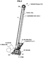
- FIG. 2 is a front view showing a configuration of the window regulator of the embodiment
- FIGS. 3A to 3E are plan views showing a configuration of a carrier plate.
- FIG. 4 is an explanatory diagram illustrating the configuration of the carrier plate and a housing.
- a window regulator 1 in the present embodiment is provided with a guide rail 2 provided along an ascending/descending direction of a window 90 of a vehicle, a carrier plate 3 that slides on the guide rail 2 and moves together with the window 90 , an ascending-side cable 41 for pulling the carrier plate 3 in the ascending direction and a descending-side cable 42 for pulling the carrier plate 3 in the descending direction, wherein the carrier plate 3 comprises an ascending-side spring housing hole 31 , a descending-side spring housing hole 32 and a holding hole 3 a , the ascending-side spring housing hole 31 housing an end of the ascending-side cable 41 and an ascending-side spring 61 provided to apply a tensile force to the ascending-side cable 41 , the descending-side spring housing hole 32 housing an end of the descending-side cable 42 and a descending-side spring 62 provided to apply a tensile force to the descending-side cable 42 , and the holding hole 3 a being used for holding the window 90 , the holding hole 3 a and
- the carrier plate 3 of the window regulator 1 can have a smaller size in the vehicle longitudinal direction than a carrier plate of a window regulator configured that a portion of a holding hole used for holding a window does not overlap a descending-side spring housing hole in the vehicle longitudinal direction.
- the window regulator in the present embodiment is a device for raising and lowering a window on, e.g., an automobile door and is installed on a door panel of an automobile.
- FIG. 1 is a general schematic diagram illustrating the window regulator 1 in the present embodiment and a door 9 of a vehicle mounting the window regulator 1 .
- FIG. 2 is an overall view showing a configuration of the window regulator 1 .
- FIGS. 3A to 3E are plan views showing a configuration of the carrier plate, wherein FIG. 3A is a top view, FIG. 3B is a front view, FIG. 3C is a left side view, FIG. 3D is a right side view, and FIG. 3E is a bottom view.
- FIG. 4 is an explanatory diagram illustrating the configuration of the carrier plate and the housing.
- the window 90 is in a fully-closed state, and the door and a window frame are indicated by dash-dot-dot lines.
- the left side of the paper is the front side in the vehicle longitudinal direction and the right side of the paper is the rear side in the vehicle longitudinal direction.
- the window regulator 1 is generally composed of the guide rail 2 which is housed in a door panel (not shown) provided on the door 9 of the vehicle and is arranged along the ascending/descending direction of the window 90 , the carrier plate 3 which slides on the guide rail 2 and moves together with the window 90 , the ascending-side cable 41 and the descending-side cable 42 which pull the carrier plate 3 , and a drive unit 5 which generates a driving force for taking up and feeding out the ascending-side cable 41 and the descending-side cable 42 .
- the vertical direction is a direction that the carrier plate 3 travels on the guide rail 2
- the upward direction is a direction that the carrier plate 3 moves toward the upper end of the guide rail 2
- the downward direction is a direction that the carrier plate 3 moves toward the lower end of the guide rail 2 .
- the guide rail 2 is formed by bending a long metal plate at a predetermined curvature and is arranged so as to tilt to the rear side in the vehicle longitudinal direction with respect to the door 9 .
- the carrier plate 3 is a plate-shaped member formed of, e.g., a resin such as polyacetal. As shown in FIGS. 3A, 3E and 4 , the carrier plate 3 has the ascending-side spring housing hole 31 (indicated by a dash-dot-dot line in FIG. 4 ) and the descending-side spring housing hole 32 (indicated by a dash-dot-dot line in FIG. 4 ).
- the ascending-side spring housing hole 31 houses an end of the ascending-side cable 41 and the ascending-side spring 61 applying a tensile force to the ascending-side cable 41 .
- the descending-side spring housing hole 32 houses an end of the descending-side cable 42 and the descending-side spring 62 applying a tensile force to the descending-side cable 42 .
- the holding hole 3 a used for holding the window 90 is formed on the carrier plate 3 .
- the holding hole 3 a is a hole penetrating the carrier plate 3 in a plate thickness direction, and a glass holder (not shown) holding the window 90 is fitted to the holding hole 3 a and fastened by a fixing member such as bolt.
- the ascending-side cable 41 is coupled to the carrier plate 3 at one end, turns at a pulley 20 provided at the top end of the guide rail 2 , and is coupled to a drum 51 of the drive unit 5 (described later) at the other end.
- the descending-side cable 42 is coupled to the carrier plate 3 at one end and is coupled to the drum 51 at the other end.
- the pulley 20 is shaft-supported by a pulley bracket 200 which is fixed to the top end of the guide rail 2 .
- the pulley bracket 200 is fixed to a door panel (not shown).
- the ascending-side cable 41 and the descending-side cable 42 are routed so as not to overlap the guide rail 2 when viewed in a direction along a rotational axis of the drum 51 .
- the drive unit 5 has a motor 50 with reducer, the cylindrical drum 51 (indicated by a dashed line in FIG. 2 ) and a housing 52 .
- the drum 51 is rotationally driven by the motor 50 and rotates to take up and feed out the ascending-side cable 41 and the descending-side cable 42 .
- the housing 52 is provided at a lower end of the guide rail 2 , and is composed of a motor housing 520 accommodating a portion of the motor 50 and holding the motor 50 , and a drum housing 521 accommodating the drum 51 .
- the motor 50 is held by the motor housing 520 and is inclined by a predetermined angle about the rotational axis of the drum 51 .
- the reducer constructed from a worm wheel, etc., is coupled to and meshes with the output shaft of the motor 50 .
- the reducer is housed in the motor housing 520 .
- the motor housing 520 and the drum housing 521 are fixed to each other by fixing portions 521 c and 521 d .
- Panel fixing portions 521 a and 521 b for fixing the housing 52 to the door panel are provided on the drum housing 521 .
- the ascending-side spring housing hole 31 is formed in a bottomed cylindrical shape opening upward and has a bottom surface which can be seen from the outside through the opening.
- One end of the ascending-side spring 61 is in contact with the bottom surface of the ascending-side spring housing hole 31 .
- the ascending-side spring housing hole 31 also has a slit 31 a (shown in FIG. 4 ) which extends in the vertical direction.
- the slit 31 a is formed as an insertion hole used when inserting the ascending-side cable 41 into the ascending-side spring housing hole 31 .
- An exit hole 31 a through which the ascending-side cable 41 extends out is formed on the bottom surface of the ascending-side spring housing hole 31 .
- the descending-side spring housing hole 32 is formed in a bottomed cylindrical shape opening downward and has a bottom surface which can be seen from the outside through the opening.
- One end of the descending-side spring 62 is in contact with the bottom surface of the descending-side spring housing hole 32 .
- the descending-side spring housing hole 32 also has a slit 32 a (shown in FIG. 4 ) which extends in the vertical direction.
- the slit 32 a is formed as an insertion hole used when inserting the descending-side cable 42 into the descending-side spring housing hole 32 .
- An exit hole 32 a through which the descending-side cable 42 extends out is formed on the bottom surface of the descending-side spring housing hole 32 .
- the bottom surface of the carrier plate 3 includes a stopper surface 30 a and an exit surface 30 b .
- the stopper surface 30 a is a surface which comes into contact with the housing 52 at a position where the carrier plate is located when the window 90 is fully opened (hereinafter, this position of the carrier plate 3 is referred to as “the bottom dead center”).
- the exit surface 30 b is a surface through which the descending-side cable 42 extends out of the descending-side spring housing hole 32 .
- the exit surface 30 b is located at a lower position than the stopper surface 30 a .
- a space for forming the holding hole 3 a can be provided on the upper side of the descending-side spring housing hole 32 in the vertical direction, and the size of the carrier plate 3 in the vehicle longitudinal direction thereby can be reduced. That is, it is possible to reduce the size of the window regulator 1 .
- the ascending-side spring housing hole 31 and the descending-side spring housing hole 32 are out of alignment in the vertical direction in such a manner that the descending-side spring housing hole 32 is located at a lower position than the ascending-side spring housing hole 31 .
- an elastic body 7 having an inverted triangle-shaped end portion is provided on the stopper surface 30 a of the carrier plate 3 .
- the elastic body 7 is arranged so that the end portion thereof protrudes from the stopper surface 30 a .
- an impact upon contact of the carrier plate 3 with the housing 52 is cushioned.
- the stopper surface 30 a of the carrier plate 3 comes into contact with the housing 52 which then receives the weight of the window 90 , and at the same time, a rotational moment about a contact point between the stopper surface 30 a and the housing 52 acts on the carrier plate 3 .
- a step surface 30 c of the carrier plate 3 is not in contact with a side surface 52 a of the housing 52 until just before the carrier plate 3 reaches the bottom dead center, and the stopper surface 30 a of the carrier plate 3 comes into contact with an upper surface 52 b of the housing 52 at the moment when the carrier plate 3 reaches the bottom dead center. Then, the rotational moment is generated due to the contact between the stopper surface 30 a of the carrier plate 3 and the upper surface 52 b of the housing 52 and acts on the carrier plate 3 , and the step surface 30 c of the carrier plate 3 then comes into contact with the side surface 52 a of the housing 52 .
- the side surface 52 a of the housing 52 serves as a prevention surface which prevents wobbling caused by tilt of the carrier plate 3 at the bottom dead center of the carrier plate 3
- the step surface 30 c of the carrier plate 3 serves as a contact surface which comes into contact with the prevention surface.
- a fitting groove 3 b to which the guide rail 2 is fitted is formed on the carrier plate 3 .
- the carrier plate 3 slides on the side end portion of the guide rail 2 in the state that the guide rail 2 is fitted to the fitting groove 3 b.
- the carrier plate 3 is configured that the holding hole 3 a (indicated by a dashed line in FIG. 3A ) and the descending-side spring housing hole 32 are aligned in the vertical direction and a portion of the holding hole 3 a overlaps the descending-side spring housing hole 32 in the vehicle longitudinal direction.
- a space for providing the holding hole 3 a can be smaller than when the holding hole 3 a and the descending-side spring housing hole 32 are not aligned in the vertical direction and do not overlap in the vehicle longitudinal direction, and the size of the carrier plate 3 in the vehicle longitudinal direction thereby can be reduced. That is, it is possible to reduce the size of the window regulator 1 .
- the holding hole 3 a of the carrier plate 3 it is possible to arrange the holding hole 3 a of the carrier plate 3 closer to the guide rail 2 . As a result, it is possible to reduce the moment acting when the carrier plate 3 is raised from, e.g., its bottom dead center.
- the farther the position of the holding hole from the guide rail 2 in the vehicle longitudinal direction the larger the distance of the holding hole 3 a from the fitting groove 3 b with which the carrier plate 3 grips the guide rail 2 , causing an increase in the rotational moment about the fitting groove 3 b .
- it is possible to prevent such increase in the rotational moment thus, it is possible to stabilize the behavior of the window 90 during when the carrier plate 3 is raised.
- the holding hole 3 a used for holding the window 90 is provided only one in number. By having such configuration, it is possible to reduce the numbers of components and assembling processes as compared to when, e.g., plural holding holes are provided.
Applications Claiming Priority (3)
| Application Number | Priority Date | Filing Date | Title |
|---|---|---|---|
| JPJP2018-029821 | 2018-02-22 | ||
| JP2018029821A JP7029975B2 (ja) | 2018-02-22 | 2018-02-22 | ウインドレギュレータ |
| JP2018-029821 | 2018-02-22 |
Publications (2)
| Publication Number | Publication Date |
|---|---|
| US20190257134A1 US20190257134A1 (en) | 2019-08-22 |
| US10975606B2 true US10975606B2 (en) | 2021-04-13 |
Family
ID=67616737
Family Applications (1)
| Application Number | Title | Priority Date | Filing Date |
|---|---|---|---|
| US16/276,000 Active 2039-05-10 US10975606B2 (en) | 2018-02-22 | 2019-02-14 | Window regulator |
Country Status (3)
| Country | Link |
|---|---|
| US (1) | US10975606B2 (ja) |
| JP (1) | JP7029975B2 (ja) |
| CN (1) | CN110185355B (ja) |
Cited By (2)
| Publication number | Priority date | Publication date | Assignee | Title |
|---|---|---|---|---|
| US11326381B2 (en) * | 2018-03-26 | 2022-05-10 | Johnan Manufacturing Inc. | Window regulator |
| US20230049045A1 (en) * | 2021-08-10 | 2023-02-16 | Johnan Manufacturing Inc. | Window regulator |
Families Citing this family (4)
| Publication number | Priority date | Publication date | Assignee | Title |
|---|---|---|---|---|
| JP6762970B2 (ja) * | 2018-01-19 | 2020-09-30 | 株式会社城南製作所 | ウインドレギュレータ |
| KR20200068426A (ko) * | 2018-12-05 | 2020-06-15 | 현대자동차주식회사 | 승강시 충격음이 저감되는 도어 글래스 어셈블리 |
| JP7384692B2 (ja) | 2020-02-12 | 2023-11-21 | 株式会社ハイレックスコーポレーション | 昇降装置 |
| JP2021156148A (ja) * | 2020-03-30 | 2021-10-07 | シロキ工業株式会社 | ワイヤ式レギュレータ |
Citations (22)
| Publication number | Priority date | Publication date | Assignee | Title |
|---|---|---|---|---|
| JPS5823391A (ja) | 1981-08-03 | 1983-02-12 | Mitsubishi Electric Corp | ジヨセフソンメモリ装置 |
| US4442632A (en) * | 1981-12-03 | 1984-04-17 | Iao Industrie Riunite S.P.A. | Window regulator, particularly for motor vehicles |
| US5740630A (en) * | 1994-03-30 | 1998-04-21 | Kuster & Co. Gmbh | Cable-driven window lift |
| US5950365A (en) * | 1996-05-10 | 1999-09-14 | Brose Fahrzeuteile Gmbh & Co. Kg | Motor-driven window lifter with electronic entrapment protection for a motor vehicle |
| US20040134130A1 (en) * | 2002-11-20 | 2004-07-15 | Dobson Simon B. | Window regulator cable assemblies |
| US20040154227A1 (en) * | 2001-03-19 | 2004-08-12 | Tatsuo Yoshimura | Curved glass support structure and wind regulator |
| US20070180773A1 (en) * | 2004-08-06 | 2007-08-09 | Fortin Raymond E | Dual-guided single rail window regulator |
| US20080236049A1 (en) | 2007-03-27 | 2008-10-02 | Hi-Lex Controls Inc. | Window carrier assembly for automotive window regulator |
| US7765739B2 (en) * | 2005-12-27 | 2010-08-03 | Honda Motor Co., Ltd. | Elevating device for window glass |
| US20100223852A1 (en) * | 2009-03-06 | 2010-09-09 | Shigeki Arimoto | Bottom drive rail-less window regulator |
| JP2011026858A (ja) | 2009-07-27 | 2011-02-10 | Hi-Lex Corporation | ウインドレギュレータ装置 |
| JP2011089311A (ja) | 2009-10-22 | 2011-05-06 | Hi-Lex Corporation | ケーブル張力付与装置およびケーブル張力付与装置を備えたウインドレギュレータ |
| JP2012057376A (ja) | 2010-09-10 | 2012-03-22 | Shiroki Corp | ウインドレギュレータ |
| CN103069094A (zh) | 2010-06-30 | 2013-04-24 | Hi-Lex株式会社 | 车窗开闭调节器 |
| CN103210166A (zh) | 2010-11-08 | 2013-07-17 | 八千代工业株式会社 | 车窗升降器 |
| JP2013207082A (ja) | 2012-03-28 | 2013-10-07 | Toshiba Corp | 窒化物半導体ショットキダイオードおよびその製造方法 |
| JP2015121059A (ja) | 2013-12-25 | 2015-07-02 | シロキ工業株式会社 | ウインドレギュレータ |
| US9163448B2 (en) * | 2011-10-25 | 2015-10-20 | Hi-Lex Corporation | Window regulator |
| US9790728B2 (en) | 2015-07-17 | 2017-10-17 | Hi-Lex Controls, Inc. | Single-rail window regulator assembly |
| US20170370145A1 (en) * | 2015-01-15 | 2017-12-28 | Johnan Manufacturing Inc. | Window regulator |
| US20190169900A1 (en) * | 2017-12-06 | 2019-06-06 | Hi-Lex Controls, Inc. | Window regulator assembly with carrier plate |
| US10604981B2 (en) * | 2017-12-22 | 2020-03-31 | Johnan Manufacturing Inc. | Window regulator and carrier plate |
Family Cites Families (12)
| Publication number | Priority date | Publication date | Assignee | Title |
|---|---|---|---|---|
| JPH0681537A (ja) * | 1992-09-01 | 1994-03-22 | Nippon Cable Syst Inc | 窓ガラス角度調節装置 |
| JP3155675B2 (ja) * | 1995-03-30 | 2001-04-16 | 株式会社大井製作所 | 窓ガラスの昇降装置 |
| KR100478051B1 (ko) * | 2002-12-17 | 2005-03-23 | 현대자동차주식회사 | 자동차용 도어 윈도우 레귤레이터의 캐리어 플레이트 |
| JP5267064B2 (ja) | 2008-11-14 | 2013-08-21 | 三菱自動車工業株式会社 | ドアガラス昇降装置 |
| JP5044002B2 (ja) | 2010-08-27 | 2012-10-10 | 株式会社ハイレックスコーポレーション | ウインドレギュレータ |
| JP5810688B2 (ja) * | 2011-07-07 | 2015-11-11 | マツダ株式会社 | ウインドレギュレータ |
| JP2013217082A (ja) | 2012-04-06 | 2013-10-24 | Hi-Lex Corporation | ウインドレギュレータ |
| JP2016088268A (ja) * | 2014-11-04 | 2016-05-23 | トヨタ自動車株式会社 | 車両用ドア構造 |
| JP6563246B2 (ja) | 2015-05-13 | 2019-08-21 | 株式会社ハイレックスコーポレーション | 移動体移動装置および窓ガラス昇降装置 |
| US9822568B2 (en) * | 2016-03-21 | 2017-11-21 | Hi-Lex Controls Inc. | Window regulator cable guide |
| CN105799467B (zh) * | 2016-05-17 | 2018-03-23 | 宁波世通汽车零部件有限公司 | 一种绳轮式升降器 |
| DE202016102999U1 (de) | 2016-06-06 | 2017-09-07 | Brose Fahrzeugteile Gmbh & Co. Kommanditgesellschaft, Bamberg | Fensterheberbaugruppe mit einem an einer Führungsschiene verschieblich geführten Mitnehmer |
-
2018
- 2018-02-22 JP JP2018029821A patent/JP7029975B2/ja active Active
-
2019
- 2019-02-14 US US16/276,000 patent/US10975606B2/en active Active
- 2019-02-21 CN CN201910129272.4A patent/CN110185355B/zh active Active
Patent Citations (26)
| Publication number | Priority date | Publication date | Assignee | Title |
|---|---|---|---|---|
| JPS5823391A (ja) | 1981-08-03 | 1983-02-12 | Mitsubishi Electric Corp | ジヨセフソンメモリ装置 |
| US4442632A (en) * | 1981-12-03 | 1984-04-17 | Iao Industrie Riunite S.P.A. | Window regulator, particularly for motor vehicles |
| US5740630A (en) * | 1994-03-30 | 1998-04-21 | Kuster & Co. Gmbh | Cable-driven window lift |
| US5950365A (en) * | 1996-05-10 | 1999-09-14 | Brose Fahrzeuteile Gmbh & Co. Kg | Motor-driven window lifter with electronic entrapment protection for a motor vehicle |
| US20040154227A1 (en) * | 2001-03-19 | 2004-08-12 | Tatsuo Yoshimura | Curved glass support structure and wind regulator |
| US20040134130A1 (en) * | 2002-11-20 | 2004-07-15 | Dobson Simon B. | Window regulator cable assemblies |
| US20070180773A1 (en) * | 2004-08-06 | 2007-08-09 | Fortin Raymond E | Dual-guided single rail window regulator |
| US7765739B2 (en) * | 2005-12-27 | 2010-08-03 | Honda Motor Co., Ltd. | Elevating device for window glass |
| US20080236049A1 (en) | 2007-03-27 | 2008-10-02 | Hi-Lex Controls Inc. | Window carrier assembly for automotive window regulator |
| US20100223852A1 (en) * | 2009-03-06 | 2010-09-09 | Shigeki Arimoto | Bottom drive rail-less window regulator |
| JP2011026858A (ja) | 2009-07-27 | 2011-02-10 | Hi-Lex Corporation | ウインドレギュレータ装置 |
| US8720114B2 (en) | 2009-07-27 | 2014-05-13 | Hi-Lex Corporation | Window regulator |
| US20120117883A1 (en) | 2009-07-27 | 2012-05-17 | Hi-Lex Corporation | Window regulator |
| JP2011089311A (ja) | 2009-10-22 | 2011-05-06 | Hi-Lex Corporation | ケーブル張力付与装置およびケーブル張力付与装置を備えたウインドレギュレータ |
| US20140007507A1 (en) * | 2010-06-30 | 2014-01-09 | Hi-Lex Corporation | Window regulator |
| CN103069094A (zh) | 2010-06-30 | 2013-04-24 | Hi-Lex株式会社 | 车窗开闭调节器 |
| JP2012057376A (ja) | 2010-09-10 | 2012-03-22 | Shiroki Corp | ウインドレギュレータ |
| CN103210166A (zh) | 2010-11-08 | 2013-07-17 | 八千代工业株式会社 | 车窗升降器 |
| US20130219794A1 (en) | 2010-11-08 | 2013-08-29 | Yachiyo Industry Co., Ltd. | Window regulator |
| US9163448B2 (en) * | 2011-10-25 | 2015-10-20 | Hi-Lex Corporation | Window regulator |
| JP2013207082A (ja) | 2012-03-28 | 2013-10-07 | Toshiba Corp | 窒化物半導体ショットキダイオードおよびその製造方法 |
| JP2015121059A (ja) | 2013-12-25 | 2015-07-02 | シロキ工業株式会社 | ウインドレギュレータ |
| US20170370145A1 (en) * | 2015-01-15 | 2017-12-28 | Johnan Manufacturing Inc. | Window regulator |
| US9790728B2 (en) | 2015-07-17 | 2017-10-17 | Hi-Lex Controls, Inc. | Single-rail window regulator assembly |
| US20190169900A1 (en) * | 2017-12-06 | 2019-06-06 | Hi-Lex Controls, Inc. | Window regulator assembly with carrier plate |
| US10604981B2 (en) * | 2017-12-22 | 2020-03-31 | Johnan Manufacturing Inc. | Window regulator and carrier plate |
Non-Patent Citations (4)
| Title |
|---|
| Office Action issued in the corresponding Chinese Patent Application No. 201910129272.4 dated May 20, 2020. |
| Office Action issued in the corresponding Chinese Patent Application No. 201910129272.4 on Jan. 14, 2021. |
| Office Action issued in the corresponding JP Patent Application No. 2018-029821 dated Feb. 25, 2020. |
| Third Party Submission filed on May 27, 2020 in the corresponding Japanese Patent Application No. 2018-029821 (received by JPO Notice dated Jun. 30, 2020). |
Cited By (3)
| Publication number | Priority date | Publication date | Assignee | Title |
|---|---|---|---|---|
| US11326381B2 (en) * | 2018-03-26 | 2022-05-10 | Johnan Manufacturing Inc. | Window regulator |
| US20230049045A1 (en) * | 2021-08-10 | 2023-02-16 | Johnan Manufacturing Inc. | Window regulator |
| US11788336B2 (en) * | 2021-08-10 | 2023-10-17 | Joiinan Manufacturing Inc. | Window regulator |
Also Published As
| Publication number | Publication date |
|---|---|
| JP2019143402A (ja) | 2019-08-29 |
| US20190257134A1 (en) | 2019-08-22 |
| JP7029975B2 (ja) | 2022-03-04 |
| CN110185355A (zh) | 2019-08-30 |
| CN110185355B (zh) | 2021-06-29 |
Similar Documents
| Publication | Publication Date | Title |
|---|---|---|
| US10975606B2 (en) | Window regulator | |
| US10604981B2 (en) | Window regulator and carrier plate | |
| US10822859B2 (en) | Window regulator | |
| US20040154227A1 (en) | Curved glass support structure and wind regulator | |
| US7500331B2 (en) | Self-driving closure device | |
| US11739581B2 (en) | Window regulator | |
| US20190257133A1 (en) | Window regulator | |
| US11326381B2 (en) | Window regulator | |
| US20180328096A1 (en) | Window regulator | |
| CN110114546B (zh) | 车辆用窗玻璃升降机构 | |
| JP2007278061A (ja) | キャリアプレートとウインドガラスの取付構造およびそれを用いたウインドレギュレータ | |
| JP6835524B2 (ja) | ウインドレギュレータ及びウインドレギュレータを備えた車両用ドア | |
| JP7240539B2 (ja) | ウインドレギュレータ | |
| US10975604B2 (en) | Window regulator | |
| US20220213729A1 (en) | Dual window regulator with optimized motor configuration | |
| US20230049045A1 (en) | Window regulator | |
| US20230295974A1 (en) | Window regulator and guide rail attaching method | |
| JP5064961B2 (ja) | ウインドレギュレータ装置 | |
| CN117627499A (zh) | 线缆安装构造及车窗开闭调节器 | |
| JP2019203273A (ja) | ウインドレギュレータ | |
| CN112486001A (zh) | 安装部结构以及图像形成装置 | |
| JP2010222916A (ja) | キャリアプレートおよびそれを備えたウインドレギュレータ | |
| JP2019031816A (ja) | 窓ガラス昇降装置 | |
| JP2020143514A (ja) | 締結構造及び締結構造を備えたウインドレギュレータ | |
| JP2007278001A (ja) | キャリアプレートとウインドガラスの取付構造およびそれを用いたウインドレギュレータ |
Legal Events
| Date | Code | Title | Description |
|---|---|---|---|
| AS | Assignment |
Owner name: JOHNAN MANUFACTURING INC., JAPAN Free format text: ASSIGNMENT OF ASSIGNORS INTEREST;ASSIGNORS:KASHIWABARA, HIDEO;NISHIZAWA, TAKESHI;SHIMIZU, HIROKI;AND OTHERS;REEL/FRAME:048336/0756 Effective date: 20190213 |
|
| FEPP | Fee payment procedure |
Free format text: ENTITY STATUS SET TO UNDISCOUNTED (ORIGINAL EVENT CODE: BIG.); ENTITY STATUS OF PATENT OWNER: LARGE ENTITY |
|
| STPP | Information on status: patent application and granting procedure in general |
Free format text: NON FINAL ACTION MAILED |
|
| STPP | Information on status: patent application and granting procedure in general |
Free format text: NOTICE OF ALLOWANCE MAILED -- APPLICATION RECEIVED IN OFFICE OF PUBLICATIONS |
|
| STPP | Information on status: patent application and granting procedure in general |
Free format text: AWAITING TC RESP., ISSUE FEE NOT PAID |
|
| STPP | Information on status: patent application and granting procedure in general |
Free format text: PUBLICATIONS -- ISSUE FEE PAYMENT RECEIVED |
|
| STPP | Information on status: patent application and granting procedure in general |
Free format text: PUBLICATIONS -- ISSUE FEE PAYMENT VERIFIED |
|
| STCF | Information on status: patent grant |
Free format text: PATENTED CASE |