US10106337B2 - Overhead conveyor system and dip coating line comprising said system - Google Patents
Overhead conveyor system and dip coating line comprising said system Download PDFInfo
- Publication number
- US10106337B2 US10106337B2 US12/918,111 US91811109A US10106337B2 US 10106337 B2 US10106337 B2 US 10106337B2 US 91811109 A US91811109 A US 91811109A US 10106337 B2 US10106337 B2 US 10106337B2
- Authority
- US
- United States
- Prior art keywords
- rail
- holding structure
- transport carriage
- conveyor system
- overhead conveyor
- Prior art date
- Legal status (The legal status is an assumption and is not a legal conclusion. Google has not performed a legal analysis and makes no representation as to the accuracy of the status listed.)
- Active, expires
Links
Images


Classifications
-
- B—PERFORMING OPERATIONS; TRANSPORTING
- B65—CONVEYING; PACKING; STORING; HANDLING THIN OR FILAMENTARY MATERIAL
- B65G—TRANSPORT OR STORAGE DEVICES, e.g. CONVEYORS FOR LOADING OR TIPPING, SHOP CONVEYOR SYSTEMS OR PNEUMATIC TUBE CONVEYORS
- B65G49/00—Conveying systems characterised by their application for specified purposes not otherwise provided for
- B65G49/02—Conveying systems characterised by their application for specified purposes not otherwise provided for for conveying workpieces through baths of liquid
- B65G49/04—Conveying systems characterised by their application for specified purposes not otherwise provided for for conveying workpieces through baths of liquid the workpieces being immersed and withdrawn by movement in a vertical direction
- B65G49/0409—Conveying systems characterised by their application for specified purposes not otherwise provided for for conveying workpieces through baths of liquid the workpieces being immersed and withdrawn by movement in a vertical direction specially adapted for workpieces of definite length
- B65G49/0436—Conveying systems characterised by their application for specified purposes not otherwise provided for for conveying workpieces through baths of liquid the workpieces being immersed and withdrawn by movement in a vertical direction specially adapted for workpieces of definite length arrangements for conveyance from bath to bath
- B65G49/044—Conveying systems characterised by their application for specified purposes not otherwise provided for for conveying workpieces through baths of liquid the workpieces being immersed and withdrawn by movement in a vertical direction specially adapted for workpieces of definite length arrangements for conveyance from bath to bath along a continuous circuit
- B65G49/045—Conveying systems characterised by their application for specified purposes not otherwise provided for for conveying workpieces through baths of liquid the workpieces being immersed and withdrawn by movement in a vertical direction specially adapted for workpieces of definite length arrangements for conveyance from bath to bath along a continuous circuit the circuit being fixed
- B65G49/0454—Conveying systems characterised by their application for specified purposes not otherwise provided for for conveying workpieces through baths of liquid the workpieces being immersed and withdrawn by movement in a vertical direction specially adapted for workpieces of definite length arrangements for conveyance from bath to bath along a continuous circuit the circuit being fixed by means of containers -or workpieces- carriers
- B65G49/0459—Conveying systems characterised by their application for specified purposes not otherwise provided for for conveying workpieces through baths of liquid the workpieces being immersed and withdrawn by movement in a vertical direction specially adapted for workpieces of definite length arrangements for conveyance from bath to bath along a continuous circuit the circuit being fixed by means of containers -or workpieces- carriers movement in a vertical direction is caused by self-contained means
-
- B—PERFORMING OPERATIONS; TRANSPORTING
- B65—CONVEYING; PACKING; STORING; HANDLING THIN OR FILAMENTARY MATERIAL
- B65G—TRANSPORT OR STORAGE DEVICES, e.g. CONVEYORS FOR LOADING OR TIPPING, SHOP CONVEYOR SYSTEMS OR PNEUMATIC TUBE CONVEYORS
- B65G49/00—Conveying systems characterised by their application for specified purposes not otherwise provided for
- B65G49/02—Conveying systems characterised by their application for specified purposes not otherwise provided for for conveying workpieces through baths of liquid
- B65G49/04—Conveying systems characterised by their application for specified purposes not otherwise provided for for conveying workpieces through baths of liquid the workpieces being immersed and withdrawn by movement in a vertical direction
-
- B—PERFORMING OPERATIONS; TRANSPORTING
- B05—SPRAYING OR ATOMISING IN GENERAL; APPLYING FLUENT MATERIALS TO SURFACES, IN GENERAL
- B05D—PROCESSES FOR APPLYING FLUENT MATERIALS TO SURFACES, IN GENERAL
- B05D1/00—Processes for applying liquids or other fluent materials
- B05D1/18—Processes for applying liquids or other fluent materials performed by dipping
-
- B—PERFORMING OPERATIONS; TRANSPORTING
- B61—RAILWAYS
- B61B—RAILWAY SYSTEMS; EQUIPMENT THEREFOR NOT OTHERWISE PROVIDED FOR
- B61B10/00—Power and free systems
- B61B10/02—Power and free systems with suspended vehicles
-
- B—PERFORMING OPERATIONS; TRANSPORTING
- B62—LAND VEHICLES FOR TRAVELLING OTHERWISE THAN ON RAILS
- B62D—MOTOR VEHICLES; TRAILERS
- B62D65/00—Designing, manufacturing, e.g. assembling, facilitating disassembly, or structurally modifying motor vehicles or trailers, not otherwise provided for
- B62D65/02—Joining sub-units or components to, or positioning sub-units or components with respect to, body shell or other sub-units or components
- B62D65/18—Transportation, conveyor or haulage systems specially adapted for motor vehicle or trailer assembly lines
-
- B—PERFORMING OPERATIONS; TRANSPORTING
- B65—CONVEYING; PACKING; STORING; HANDLING THIN OR FILAMENTARY MATERIAL
- B65G—TRANSPORT OR STORAGE DEVICES, e.g. CONVEYORS FOR LOADING OR TIPPING, SHOP CONVEYOR SYSTEMS OR PNEUMATIC TUBE CONVEYORS
- B65G49/00—Conveying systems characterised by their application for specified purposes not otherwise provided for
- B65G49/02—Conveying systems characterised by their application for specified purposes not otherwise provided for for conveying workpieces through baths of liquid
- B65G49/04—Conveying systems characterised by their application for specified purposes not otherwise provided for for conveying workpieces through baths of liquid the workpieces being immersed and withdrawn by movement in a vertical direction
- B65G49/0409—Conveying systems characterised by their application for specified purposes not otherwise provided for for conveying workpieces through baths of liquid the workpieces being immersed and withdrawn by movement in a vertical direction specially adapted for workpieces of definite length
- B65G49/0436—Conveying systems characterised by their application for specified purposes not otherwise provided for for conveying workpieces through baths of liquid the workpieces being immersed and withdrawn by movement in a vertical direction specially adapted for workpieces of definite length arrangements for conveyance from bath to bath
- B65G49/044—Conveying systems characterised by their application for specified purposes not otherwise provided for for conveying workpieces through baths of liquid the workpieces being immersed and withdrawn by movement in a vertical direction specially adapted for workpieces of definite length arrangements for conveyance from bath to bath along a continuous circuit
- B65G49/045—Conveying systems characterised by their application for specified purposes not otherwise provided for for conveying workpieces through baths of liquid the workpieces being immersed and withdrawn by movement in a vertical direction specially adapted for workpieces of definite length arrangements for conveyance from bath to bath along a continuous circuit the circuit being fixed
- B65G49/0454—Conveying systems characterised by their application for specified purposes not otherwise provided for for conveying workpieces through baths of liquid the workpieces being immersed and withdrawn by movement in a vertical direction specially adapted for workpieces of definite length arrangements for conveyance from bath to bath along a continuous circuit the circuit being fixed by means of containers -or workpieces- carriers
- B65G49/0463—Conveying systems characterised by their application for specified purposes not otherwise provided for for conveying workpieces through baths of liquid the workpieces being immersed and withdrawn by movement in a vertical direction specially adapted for workpieces of definite length arrangements for conveyance from bath to bath along a continuous circuit the circuit being fixed by means of containers -or workpieces- carriers movement in a vertical direction is caused by lifting means or fixed or adjustable guiding means located at the bath area
Definitions
- the invention relates to an overhead conveyor system for transporting objects, in particular for transporting vehicle bodies in a treatment plant, having:
- the invention relates to a dip treatment plant, having:
- the term “below” is used when a component is arranged lower down than a further component. This does not mean that the component arranged lower down has to overlap with the component arranged higher up, as seen in the vertical direction. The latter condition is expressed in the text that follows by the term “under”.
- the terms “above” and “over” are correspondingly used of a component which is arranged higher up than a further component.
- the securing device is arranged under the rail on which the transport carriage runs, and in the case of U.S. Pat. No. 6,571,970 B1 the securing device may be moved in the vertical direction by means of a telescopic device.
- the drive means which for example include a drive carriage and where appropriate further components which are required to convey the transport carriage along the rail, are usually located in close proximity to the rail.
- the vehicle body is also located under the rail, the drive carriage and any further conveying components present.
- a relatively complicated cleaning procedure is performed in which the vehicle body is cleaned, degreased and so on. It may happen that particles of dirt, oil or other means of soiling fall(s) off the conveying components concerned, from above the objects to be treated. In this case, the means of soiling may land on the vehicle body, which impairs the outcome of the cleaning procedure and may result in lower-quality painting.
- a cover which protects the vehicle body or other objects to be treated and which is arranged along the path of conveying the vehicle body and over the latter is extremely complicated to construct and is moreover expensive.
- the present invention is directed to resolving these and other matters.
- the stated object may be achieved in an overhead conveyor system of the type mentioned at the outset in that
- the space over the securing device and indeed the space over the object secured thereto may be kept free inasmuch as, in particular, no components that are required to convey the transport carriage are arranged there.
- the securing device includes a holding structure with securing means which is carried only by way of a side surface of a further component of the transport carriage.
- the securing device is held by a bracket which extends over and above the securing device, the securing device is secured to the holding structure by only one side.
- no components of the transport carriage that hold the securing device are arranged over the securing device.
- the holding structure is mounted on the further component of the transport carriage such that it is rotatable about a horizontal axis of rotation.
- the object it is possible for the object to achieve a movement sequence which is a superposition of a horizontal linear movement and a rotary movement about the horizontal axis of rotation. This does not mean that the movement of the object is always predetermined by a superposition of this kind.
- a horizontal linear movement alone, or a rotation about the horizontal axis of rotation alone, are also possible.
- the axis of rotation to be arranged very close to the centre of gravity of the object, which is advantageous from the point of view of the forces that act on the transport carriage when the object rotates.
- the further component of the transport carriage, which holds the holding structure is a vertically movable slide. In this way, the object may also be moved in a vertical linear movement.
- the slide is vertically movable by means of a telescopic device which may be retracted or extended in the vertical direction.
- This telescopic device may hold the vertically movable slide, or the latter may itself be a movable part of the telescopic device.
- the transport carriage may substantially take the form of an L-shaped bracket, with the securing device representing the short, horizontal bar and the telescopic device approximately representing the long, vertical bar of the L. If no vertical movement is desirable or necessary, then a rigid connection may also be provided instead of the telescopic device.
- the securing device is mounted such that it is rotatable about a vertical axis of rotation.
- the said degrees of freedom of movement are particularly advantageous if the object is to be guided through a dip bath in a dip treatment plant.
- transport carriage includes as the drive means a drive carriage which may be moved by motor on the rail, known components of overhead conveyor systems may be used, the use whereof is already known and which have been tried and tested.
- the telescopic device When the telescopic device is used, it is advantageous if the telescopic device is mounted on the drive carriage of the transport carriage such that it is rotatable about the vertical axis of rotation. In this way, the transport carriage as a whole may be kept relatively compact and yet provide the object with a large number of possible degrees of freedom of movement.
- the securing means may include a support structure which is arranged parallel to and below the rail and which supports the holding carriage.
- the securing means may advantageously be constructed such that they include a guide roller which is mounted on the transport carriage, is rotatable about a vertical axis of rotation and is guided in a guide rail that is complementary thereto, with the guide rail running below the drive rail and parallel thereto.
- FIG. 1 shows in side view a cataphoretic dip coating plant for vehicle bodies
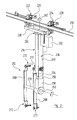
- FIGS. 2 and 3 show, in perspective from different directions of view, a transport carriage having a telescopic arm as used to convey the vehicle bodies to be coated in the dip coating plant from FIG. 1 , during the return procedure from the exit of the plant to its entry;
- FIG. 4 shows, in perspective and on a larger scale, a detailed view of a drive carriage of the transport carriage as used in the cataphoretic dip coating plant from FIG. 1 , in which a mechanism for rotating the telescopic arm is shown;
- FIGS. 5 and 6 show, in perspective and on a larger scale, a detailed view from different directions of view of a side guide of the telescopic arm;
- FIG. 7 shows, in perspective, a detailed view on a larger scale of a securing device of the transport carriage as used in the dip coating plant from FIG. 1 ;
- FIGS. 8A to 8E show different views of a first exemplary embodiment of the telescopic arm as used in the transport carriage of the cataphoretic dip coating plant from FIG. 1
- FIGS. 9A to 9E show different views of a second exemplary embodiment of the telescopic arm as used in the transport carriage of the cataphoretic dip coating plant from FIG. 1 ;
- FIGS. 10 to 18 show phases in the dipping of a vehicle body into the dip bath of the cataphoretic dip coating plant from FIG. 1 , from different perspectives.
- FIGS. 1 to 18 illustrate a cataphoretic dip coating plant 200 .
- the latter includes a dip bath 202 filled with liquid paint. Particles of paint migrate within an electrical field located between vehicle bodies 204 and anodes which are arranged along the path of movement of the vehicle bodies 204 and are not illustrated for reasons of clarity, towards the vehicle bodies 204 and are deposited thereon.
- the vehicle bodies 204 are guided through the plant, and in particular through the dip bath 202 and the paint therein, with the aid of a conveyor system 206 .
- the conveyor system 206 includes a plurality of transport carriages 208 which for their part have a drive carriage 210 and a holding carriage 212 , which are coupled to one another by way of a telescopic device 214 which will be explained in detail below.
- a guide rail 218 having an upwardly open U-shaped profile is also included in the drive rail 216 .
- the direction of movement in which the vehicle bodies 204 are conveyed by means of the conveyor system 206 is illustrated by an arrow 220 in FIG. 1 .
- the drive rail 216 and the guide rail 218 are offset outwards, as seen in the direction perpendicular to the direction of movement 220 , in relation to the centre of the dip bath 202 , with the guide rail 218 extending further out than the drive rail 216 .
- the drive carriages 210 are basically of a construction that is known from conventional electric overhead conveyors. Each of these drive carriages 210 has a travelling gear 222 which leads in the direction of movement 220 , called the “leader” in the language of the art, and a further travelling gear 224 which follows in the direction of movement 220 and is called the “trailer” in the language of the art.
- the leader 222 and trailer 224 are equipped in known manner with guide and support rollers, which are not designated by their own reference numeral here and which roll on different surfaces of the I-shaped profile of the drive rail 216 . At least one of the rollers of the leader 222 or trailer 224 serves as a drive roller and for this purpose may be rotated by an electric motor 226 or 228 .
- the transport carriage 208 which is driven by way of the drive carriage 210 , may where appropriate also pass over inclines if the drive rail 216 has to extend at an angle in certain regions to adapt the path of conveying to local conditions.
- connection frame 230 which is particularly readily visible in FIGS. 2 to 4 .
- connection frame 230 for its part, in known manner carries a control device 232 which can communicate with the central control of the dip coating plant 200 and where appropriate with the control devices 232 of the other drive carriages 210 in the dip coating plant 200 . In this way, it is possible to move the different transport carriages 208 largely independently.
- the telescopic device 214 which couples the drive carriage 210 to the holding carriage 212 includes a three-part, vertically extending telescopic arm 234 which is variable in length. This is connected at its upper end to the end face of a toothed wheel 236 having an external toothing 238 in such a manner that it cannot rotate in relation thereto, such that the longitudinal axis of the telescopic arm 234 and the axis of rotation 240 of the toothed wheel 236 (cf. FIG. 4 ) coincide or at least lie closely next to one another.
- the toothed wheel 236 is for its part mounted rotatably on the connection frame 230 , approximately centrally between the leader 222 and the trailer 224 , such that the axis of rotation 240 extends vertically.
- the toothed wheel 236 can be driven by means of a servo motor 242 which communicates with the control device 232 of the drive carriage 210 and which for this purpose drives a toothed wheel 244 engaging in the external toothing 238 of the toothed wheel 236 .
- the telescopic arm 234 can be turned about the axis of rotation 240 in either the clockwise or the anticlockwise direction, depending on the direction of rotation of the pinion 244 .
- the servo motor 242 and the pinion 244 are shown only in FIG. 4 , for the sake of clarity, and for this reason the connection frame 230 is partly cut away there.
- the telescopic arm 234 includes an upper telescopic part 246 . This carries, at its end remote from the toothed wheel 236 , and on a transverse crosspiece 248 , a guide roller 250 which can turn freely about a vertical axis of rotation 252 and which runs in the U-shaped profile of the guide rail 218 , as is in particular visible from FIGS. 5 and 6 . In this way, the telescopic arm 234 is prevented from tilting out of the vertical in a plane which is perpendicular to the direction of movement 220 .
- the telescopic arm 234 includes a central telescopic part 254 and a lower telescopic part 256 .
- the telescopic parts 246 , 254 and 256 are displaceable in relation to one another, whereof more details will be given in the text that follows.
- the lower telescopic part 256 serves as a slide 256 which is movable inside the central telescopic part 254 , and will be designated as such in the text that follows.
- a rotary peg 260 In the lower free end region 258 of the slide 256 there is mounted a rotary peg 260 .
- the latter defines a horizontal axis of rotation 262 shown in FIGS. 2 and 3 .
- the rotary peg 260 can be turned in both directions of rotation about the axis of rotation 262 by way of a geared motor 264 (cf. FIG. 7 , where the cover is removed) which is entrained by the slide 256 in its lower end region 258 and communicates with the control device 232 of the transport carriage 208 .
- the holding carriage 212 has two mutually parallel longitudinal bars 266 and 268 of rectangular cross-section, which are connected centrally by a transverse crosspiece 270 of circular cross-section, and which take the form of hollow profiles.
- the rotary peg 260 of the slide 256 is connected to the outer surface of the longitudinal bar 266 of the holding carriage 212 such that it cannot rotate in relation thereto, with the rotary peg 260 and the transverse bar 270 of the holding carriage 212 running coaxially with respect to one another.
- Securing means 272 are mounted on the end sides of the longitudinal bars 266 and 268 and can be used to detachably secure a vehicle body 204 to be coated to the holding carriage 212 in a manner known per se.
- the slide 256 carries the holding carriage 212 by way of the rotary peg 260 only on one side, such that the transport carriage 208 as a whole takes the form of an L-shaped bracket.
- the transport carriage 208 may be aligned during its movement along the drive rail 216 such that the holding carriage 212 , with the securing means 272 , is arranged laterally offset from the drive rail 216 .
- This makes it possible to ensure that none of the components of the conveyor system 206 , for example the drive rail 216 or the drive carriage 210 , among others, is arranged in the space vertically over the holding carriage 212 with the securing means 272 .
- the risk of the vehicle body 204 becoming soiled by dirt such as dust, oil or similar falling off components of the conveyor system 206 is thus reduced.
- the telescopic parts 246 , 254 and 256 of the telescopic arm 234 may be moved relative to one another.
- the cross-sections of the individual telescopic parts 246 , 254 and 256 are constructed to complement one another such that the central telescopic part 254 can be displaced in a manner guided inside the upper telescopic part 246 and the slide 256 can be displaced in a manner guided inside the central telescopic part 254 .
- the central telescopic part 254 carries at the end face of its upper end, which is always located inside the upper telescopic part 246 , a servo motor 274 which communicates with the control device 232 of the transport carriage 208 and can drive a drive pinion 276 in two directions of rotation.
- a chain 278 runs both over the drive pinion 276 of the servo motor 274 and over a return pinion 280 which is mounted at the lower end of the central telescopic part 254 , which projects downwards out of the upper telescopic part 246 .
- the chain 278 is connected, at its side 282 on the left in FIG.
- connection pin 284 which for its part is attached non-movably to the upper telescopic part 246 .
- the opposite, second side 286 of the chain 278 is coupled to a connection pin 288 which for its part is connected non-movably to the slide 256 of the telescopic arm 234 .
- the connection pin 288 of the slide 256 runs in a slot 290 which is provided in a side wall of the central telescopic part 254 , whereas the connection pin 278 of the upper telescopic part 246 is guided laterally past the central telescopic part 254 .
- FIG. 9 An alternative embodiment of the telescopic arm 234 is shown in FIG. 9 in partly cut-away views.
- the chain 278 runs over the drive pinion 276 of the servo motor 274 and over a first coupling pinion 292 and a second coupling pinion 294 .
- the coupling pinions 292 and 294 each carry a spur wheel in coaxial manner; these are not visible in the views of FIG. 9 .
- the external toothing of the spur wheel on the coupling pinion 292 engages in a toothed rack 296 , the latter being non-movably connected to the upper telescopic part 246 of the telescopic arm 234 , and is arranged in the upper region of the central telescopic part 254 .
- the coupling pinion 294 is arranged in the lower region of the central telescopic part 254 ; the toothing of the spur wheel mounted thereon engages in a toothed rack 298 which is non-movably connected to the slide 256 of the telescopic arm 234 .
- the spur wheel (not visible) on the coupling pinion 294 extends through a side wall of the central telescopic part 254 .
- the raising and lowering movement of the telescopic parts 246 and 254 and the slide 256 may also be brought about by a sliding chain or similar devices.
- the vehicle bodies 204 to be coated are fed in a substantially horizontal alignment in FIG. 1 (cf. arrow 220 ) from a pre-treatment station in which the vehicle bodies 204 are prepared for the coating operation in known manner by being cleaned, degreased, etc.
- the slide 256 is moved to its topmost position, in which the telescopic parts 256 , 254 and 256 of the telescopic arm 234 are retracted inside one another, such that the latter adopts its smallest possible length.
- the corresponding position can be seen in perspective in FIG. 10 .
- the drive carriage 210 of the corresponding transport carriage 208 is fed, with the aid of the electric motors 226 and 228 , along the drive rail 216 to the dip bath 202 , the associated holding carriage 212 being entrained by way of the telescopic device 214 .
- the guide roller 250 on the upper telescopic part 246 of the telescopic arm 234 rolls in the U-shaped profile of the guide rail 218 , although this does not serve to support the weight.
- the weight of the transport carriage 208 and the vehicle body 204 secured thereto is entirely carried by the drive rail 216 by way of the drive carriage 210 .
- the slide 256 carrying the vehicle body 204 by way of the transport carriage 208 is progressively lowered, by the telescopic arm 234 being extended in the manner described in the preceding text, with the aid of the servo motor 274 .
- the rotary peg 260 and hence the holding carriage 212 with the securing means 272 and the vehicle body 204 secured thereto are simultaneously turned with the aid of the geared motor 264 about the axis of rotation 262 .
- the overall movement of the vehicle body 204 can be regarded as the superposition of three movements, namely a horizontal linear movement (arrow 220 ) along the drive rail 216 , a vertical linear movement along the axis of rotation 240 and hence also along the longitudinal axis of the telescopic arm 234 , and a rotary movement, clockwise as seen in FIG. 1 , about the axis of rotation 262 of the rotary peg 260 .
- the vehicle body 204 is “wound” over the end wall of the dip bath 202 on the entry side. The corresponding position is illustrated in perspective in FIG. 11 .
- the vehicle body 204 is substantially vertical, as illustrated in FIG. 12 .
- the vehicle body 204 is still relatively close to the end wall of the dip bath 202 on the entry side.
- the transport carriage 208 continues to move and hence the spacing between the centre of the vehicle body 204 and the end wall of the dip bath 202 on the entry side grows, the rotary peg 260 and hence the vehicle body 204 are turned further clockwise, such that the vehicle body 204 begins to lie on its back, and this is illustrated in FIG. 13 .
- the speed of movement in the horizontal direction and the speed of rotation can in this case be matched to one another such that the front end of the vehicle body 204 maintains approximately the same spacing from the end wall of the dip bath 202 on the entry side during this dipping movement.
- the vehicle body 204 is completely immersed in the liquid paint.
- the vehicle body 204 is conveyed further through the dip bath 202 , at first in this position, with the aid of the transport carriage 208 until it has come closer to the end wall of the dip bath 202 on the exit side.
- the procedure of removing the vehicle body 204 from the bath begins.
- This procedure can once again be regarded as the superposition of three movements, namely the horizontal linear movement in the direction of conveying 220 , the vertical movement along the axis of rotation 240 and hence also along the longitudinal axis of the telescopic arm 234 , and the rotary movement about the axis of rotation 262 of the rotary peg 260 .
- First the vehicle body 204 is set vertical by the rotary peg 260 continuing to turn clockwise.
- the vehicle body 204 is “wound” by the telescopic arm 234 being retracted and hence by an upward movement of the slide 256 and a continuation of the rotary movement up over the end wall of the dip bath 202 on the exit side (cf. FIG. 7 ), until a horizontal position of the freshly coated vehicle body 204 is reached again in the direction of conveying 220 downstream of the dip bath 202 , as illustrated in FIG. 18 .
- the dip coating plant 200 described may also be used to dip coat relatively small objects (small articles).
- holding baskets for example (not themselves shown) containing objects to be coated, which are small parts (not illustrated), loosely piled together for example, may be secured to the holding carriage 212 . It will be appreciated that holding baskets of this kind are not guided through the dip bath 202 in a position in which their loading opening points downwards and objects to be coated could fall out.
- the telescopic arm 234 may be turned about the vertical axis of rotation 240 by way of the servo motor 242 .
- the telescopic arm 234 adopts a position in respect of its vertical axis of rotation 240 in which the rotary peg 260 is aligned on the slide 256 such that its horizontal axis of rotation 262 is perpendicular to the direction of movement 220 .
- the telescopic arm 234 is held in this position by an appropriate locking of the servo motor 242 .
- the telescopic arm 234 can be turned about the vertical axis of rotation 240 only becomes relevant, in the kinematic arrangement shown in FIGS. 1 and 10 to 18 , once the vehicle bodies 204 have left the dip bath 202 and are removed from the transport carriages 208 for further processing. The transport carriages 208 then have to be guided back to the entry of the dip coating plant 200 so that they can be laden again there with vehicle bodies 204 which have yet to be coated.
- the holding carriage 212 is turned in relation to the connection frame 230 of the drive carriage 210 about the vertical axis of rotation 240 until the rotary peg 260 on the slide 256 is aligned parallel with the direction of movement 220 , by the servo motor 242 being actuated and this turning the toothed wheel 236 on the upper telescopic part 246 of the telescopic arm 234 .
- the holding carriage 212 is brought by a corresponding rotation of the rotary peg 260 by way of the geared motor 264 into a position in which its longitudinal bars 266 and 268 are vertical. This position is shown in FIGS. 2 and 3 . In FIG.
- a transport carriage 208 can be seen which is guided back to the entry of the dip coating plant 200 in this “return position” on a drive rail 216 ′ which runs parallel to the drive rail 216 and is connected thereto by way of a curved rail part (not visible).
- transport carriage 208 it is also possible for the transport carriage 208 to be transferred from the drive rail 216 to the drive rail 216 ′ by means of a transverse displacement without the need for a curved rail part connecting the drive rails 216 , 216 ′.
- the sequence of movements of the vehicle body 204 is merely one example.
- the structural construction of the transport carriage 208 allows a number of other kinematic arrangements which can respectively be adapted to the type of vehicle body 3 .
- the vehicle body 204 may be guided through the dip bath 202 “roof upwards”.
- the axis of rotation 262 of the holding carriage 212 it is possible for the axis of rotation 262 of the holding carriage 212 to be guided just above the liquid level of the liquid in the dip bath 202 . In this case, the vehicle body will be guided through the dip bath 202 “roof downwards”.
- a vehicle body 204 may also be guided through this transversely and not in the longitudinal direction as illustrated in FIGS. 10 to 18 . It is also possible to rotate the telescopic arm 234 about the vertical axis of rotation 240 far enough for the rotary peg 260 or the axis of rotation thereof 262 to form an angle of between 0 and 90° with the direction of movement 220 .
- the telescopic arm 234 can be rotated back and forth about the vertical axis of rotation 240 while the vehicle body 204 is guided through the dip bath 202 , as a result of which a “rolling” motion of the vehicle body 204 in the dip bath 202 can be achieved.
- the vehicle body 204 can perform a sequence of movements which can be regarded as the superposition of four movements, namely a horizontal linear movement (corresponding to the direction of movement 220 ), a vertical linear movement along the axis of rotation 240 and hence along the longitudinal axis of the telescopic arm 234 , a rotary movement about the horizontal axis of rotation 262 of the rotary peg 260 , and a rotary movement about the vertical axis of rotation 240 of the telescopic arm 234 .
- a horizontal linear movement corresponding to the direction of movement 220
- a rotary movement about the horizontal axis of rotation 262 of the rotary peg 260 a rotary movement about the vertical axis of rotation 240 of the telescopic arm 234 .
- the conveyor system 206 which takes the form of an overhead conveyor system, requires no further structures to the right and/or left of the dip bath 202 , as are required in plant of different design. This means that the dip coating plant 200 can be kept relatively narrow overall.
- the lower end region 258 of the slide 256 carrying the horizontal rotary peg 262 is lowered into the liquid in the bath.
- the horizontal axis of rotation 260 may be arranged close to the centre of gravity of the vehicle body 204 supported by the holding carriage 212 . This results in a more favourable distribution of forces during the sequence of movements for the vehicle body than is the case in known systems in which the axis of rotation lies relatively far away from the centre of gravity of the vehicle body.
Applications Claiming Priority (4)
| Application Number | Priority Date | Filing Date | Title |
|---|---|---|---|
| DE102008010401.9 | 2008-02-21 | ||
| DE102008010401 | 2008-02-21 | ||
| DE102008010401A DE102008010401A1 (de) | 2008-02-21 | 2008-02-21 | Hängebahnsystem und Tauchbehandlungsanlage mit einem solchen |
| PCT/EP2009/000496 WO2009103400A1 (de) | 2008-02-21 | 2009-01-27 | Hängebahnsystem und tauchbehandlungsanlage mit einem solchen |
Publications (2)
| Publication Number | Publication Date |
|---|---|
| US20110017132A1 US20110017132A1 (en) | 2011-01-27 |
| US10106337B2 true US10106337B2 (en) | 2018-10-23 |
Family
ID=40481885
Family Applications (1)
| Application Number | Title | Priority Date | Filing Date |
|---|---|---|---|
| US12/918,111 Active 2030-08-23 US10106337B2 (en) | 2008-02-21 | 2009-01-27 | Overhead conveyor system and dip coating line comprising said system |
Country Status (15)
| Country | Link |
|---|---|
| US (1) | US10106337B2 (es) |
| EP (1) | EP2242712B1 (es) |
| JP (1) | JP2011517306A (es) |
| KR (1) | KR101637615B1 (es) |
| CN (2) | CN106494887A (es) |
| BR (1) | BRPI0907587A2 (es) |
| CA (1) | CA2715404C (es) |
| DE (1) | DE102008010401A1 (es) |
| ES (1) | ES2391247T3 (es) |
| MX (1) | MX2010009042A (es) |
| PL (1) | PL2242712T3 (es) |
| RU (1) | RU2494032C2 (es) |
| UA (1) | UA103891C2 (es) |
| WO (1) | WO2009103400A1 (es) |
| ZA (1) | ZA201004660B (es) |
Cited By (2)
| Publication number | Priority date | Publication date | Assignee | Title |
|---|---|---|---|---|
| US20180099681A1 (en) * | 2015-03-21 | 2018-04-12 | Eisenmann Se | Transport carriage and system for transporting objects |
| US11072501B2 (en) * | 2019-06-27 | 2021-07-27 | Sst Systems, Inc. | Finishing system and method of operating |
Families Citing this family (32)
| Publication number | Priority date | Publication date | Assignee | Title |
|---|---|---|---|---|
| DE102011013415B4 (de) * | 2011-03-09 | 2015-12-17 | Eisenmann Ag | Tauchbehandlungsanlage für Fahrzeugkarosserien und Verfahren zum Betreiben einer solchen |
| ITMI20110703A1 (it) | 2011-04-27 | 2012-10-28 | Geico Spa | Stazione per il trattamento ad immersione di scocche |
| DE102011082798A1 (de) * | 2011-09-15 | 2013-03-21 | Dürr Systems GmbH | Fördervorrichtung und Verfahren zum Fördern von Werkstücken durch einen Behandlungsbereich |
| ITMI20112090A1 (it) | 2011-11-17 | 2013-05-18 | Geico Spa | Impianto rapido per il trattamento ad immersione di scocche |
| DE102012003271B4 (de) | 2012-02-21 | 2017-06-01 | Eisenmann Se | Tauchbehandlungsanlage |
| CN102616539B (zh) * | 2012-03-07 | 2014-04-16 | 江苏长虹汽车装备集团有限公司 | 一种汽车涂装输送机及其用途 |
| US9016464B2 (en) | 2012-04-04 | 2015-04-28 | Sst Systems, Inc. | Tilting multiplier |
| US9468944B2 (en) | 2013-05-17 | 2016-10-18 | Sst Systems, Inc. | System and method with multi-axis tilting |
| DE102013012485A1 (de) * | 2013-07-26 | 2015-02-19 | Eisenmann Ag | Verfahren und Anlage zur Oberflächenbehandlung von Fahrzeugkarosserien |
| CN103708176B (zh) * | 2013-12-18 | 2015-10-28 | 东风设计研究院有限公司 | 汽车车身涂装车间摩擦输送专用台车 |
| ITMI20132152A1 (it) | 2013-12-20 | 2015-06-21 | Geico Spa | Impianto per il trattamento ad immersione di scocche |
| CN104973511A (zh) * | 2015-06-26 | 2015-10-14 | 何强辉 | 一种汽车涂装前处理电泳空中自行小车用自动翻转吊具 |
| CN105366301B (zh) * | 2015-11-23 | 2018-05-04 | 中国汽车工业工程有限公司 | 单电机驱动式翻转机 |
| DE102016106662A1 (de) * | 2016-03-09 | 2017-09-14 | Fontaine Holdings Nv | Anlage zur Feuerverzinkung und Feuerverzinkungsverfahren, insbesondere für die Großserienproduktion |
| DE102016105563A1 (de) * | 2016-03-24 | 2017-09-28 | Dürr Systems Ag | Tauchbehandlungsanlage sowie Verfahren zum Betreiben einer Tauchbehandlungsanlage |
| US10384873B2 (en) * | 2016-05-06 | 2019-08-20 | Comau Llc | Inverted carrier lift device system and method |
| AT520118B1 (de) * | 2017-06-30 | 2021-06-15 | Alex Fehberger | Transportvorrichtung und Verfahren zum Tauchlackieren |
| DE102017118561A1 (de) * | 2017-08-15 | 2019-02-21 | Eisenmann Se | Fördervorrichtung zur Förderung von Werkstücken in einer Oberflächenbehandlungsanlage |
| US10457493B1 (en) | 2018-08-08 | 2019-10-29 | Sst Systems, Inc. | Indexing conveyor system and method |
| CN110534472B (zh) * | 2019-09-06 | 2021-05-25 | 杭州众硅电子科技有限公司 | 一种晶圆传输机械手及其晶圆翻转方法 |
| CN109484802A (zh) * | 2018-11-06 | 2019-03-19 | 江苏长虹机械设计院有限公司 | 垂直双链输送机 |
| CN109516115B (zh) * | 2019-01-08 | 2020-07-17 | 江苏同和智能装备有限公司 | 一种全自动汽车涂装输送机 |
| IT201900010710A1 (it) * | 2019-07-02 | 2021-01-02 | Jiangsu Changhong Intelligent Equip Co Ltd | Apparato per il trattamento superficiale di veicoli o parti di veicoli |
| US11420853B2 (en) | 2019-10-03 | 2022-08-23 | Comau Llc | Assembly material logistics system and methods |
| WO2021252329A1 (en) | 2020-06-08 | 2021-12-16 | Comau Llc | Assembly material logistics system and methods |
| CN114476557A (zh) * | 2020-11-13 | 2022-05-13 | 山东贝格尔防护材料科技有限公司 | 一种车架高效率电泳作业浸浴输送装置 |
| RU202793U1 (ru) * | 2020-11-25 | 2021-03-05 | Акционерное общество «АВТОВАЗ» | Подвеска для крепления изделий на конвейере |
| CN112978264B (zh) * | 2021-02-09 | 2022-11-15 | 中车株洲车辆有限公司 | 一种侧柱输送装置以及铁路货车侧柱生产线 |
| CN113000291B (zh) * | 2021-03-02 | 2024-04-26 | 广东省漆色彩新型材料有限公司 | 一种减速器箱盖防腐防锈涂层制作涂装系统 |
| DE102021206571A1 (de) | 2021-06-24 | 2022-12-29 | Dürr Systems Ag | Behandlungsanlage, Verfahren zum Behandeln von Werkstücken und Verfahren zum Umbau einer Behandlungsanlage |
| CN114405713B (zh) * | 2021-12-16 | 2023-03-17 | 盐城科奥机械有限公司 | 一种悬挂链式工件防锈处理流水线 |
| CN117068647B (zh) * | 2023-10-17 | 2023-12-22 | 江苏东冶轧辊有限公司 | 一种轧辊生产用运输设备及其使用方法 |
Citations (35)
| Publication number | Priority date | Publication date | Assignee | Title |
|---|---|---|---|---|
| JPS59137220U (ja) | 1983-03-01 | 1984-09-13 | 株式会社中央製作所 | 被表面処理物用収納容器の回動装置 |
| US4772374A (en) | 1983-11-14 | 1988-09-20 | Prime-Coat Technology, Inc. | Electrodeposition system and method therefor |
| JPH01139410A (ja) | 1987-11-20 | 1989-05-31 | Tsubakimoto Chain Co | L形ハンガーを有する吊下げ搬送装置 |
| JPH01129270U (es) | 1988-02-29 | 1989-09-04 | ||
| GB2224252A (en) | 1988-10-28 | 1990-05-02 | Tsubakimoto Chain Co | Conveying apparatus having L-shaped hanger |
| JPH02274486A (ja) | 1989-04-18 | 1990-11-08 | Matsushita Electric Ind Co Ltd | 共用外部軸を有するロボットシステム |
| JPH033811A (ja) | 1989-05-31 | 1991-01-09 | Tsubakimoto Chain Co | 搬送物の傾斜搬送装置 |
| GB2233622A (en) | 1989-07-10 | 1991-01-16 | Webb Int Co Jervis B | Conveyor systems. |
| JPH0369567U (es) | 1989-11-10 | 1991-07-10 | ||
| JPH06135508A (ja) | 1992-10-28 | 1994-05-17 | Okamura Corp | スタッカークレーンの走行及び荷台の昇降制御方法及び装置 |
| DE9408846U1 (de) | 1994-05-30 | 1994-09-01 | Ehrenleitner Franz | Tragvorrichtung |
| DE4326563A1 (de) | 1993-08-07 | 1995-02-09 | Rainer F Tracksdorf | Fördereinrichtung für Fahrzeugkarosserien |
| JPH0797009A (ja) | 1993-09-27 | 1995-04-11 | Mazda Motor Corp | 物品搬送制御装置 |
| US5531830A (en) | 1989-09-26 | 1996-07-02 | Honda Giken Kogyo Kabushiki Kaisha | Surface treatment apparatus |
| JP2000043712A (ja) | 1998-07-31 | 2000-02-15 | Daifuku Co Ltd | 吊下げ搬送装置 |
| DE10057150A1 (de) | 2000-11-17 | 2002-05-29 | Audi Ag | Vorrichtung zum Ein- und Austauschen eines Substrats |
| US6419983B1 (en) | 1996-10-04 | 2002-07-16 | ABB Fläkt Aktiebolag | Method of introducing and removing workpieces, particularly vehicle bodies, an apparatus and system for the surface treatment of workpieces |
| US20030056723A1 (en) | 2001-01-29 | 2003-03-27 | Franz Ehrenleitner | Installation for treating, especially painting, objects, especially vehicle bodies |
| US6571970B1 (en) * | 2000-10-16 | 2003-06-03 | Rapistan Systems Advertising Corp. | Monorail telescopic carrier |
| JP2003237563A (ja) | 2002-02-19 | 2003-08-27 | Daifuku Co Ltd | 吊り下げ搬送設備 |
| DE10306826A1 (de) * | 2003-02-19 | 2004-04-15 | Manz Galvanotechnik Gmbh | Vorrichtung zur oberflächentechnischen Behandlung von Schüttgütern in Flüssigkeiten |
| DE10261337A1 (de) | 2002-12-28 | 2004-07-08 | Volkswagen Ag | Verfahren zum Fördern von Karosserien in einer Montagelinie |
| JP2004315837A (ja) | 2003-04-11 | 2004-11-11 | Trinity Ind Corp | ワークの処理システム |
| US20050061239A1 (en) * | 2003-08-13 | 2005-03-24 | Hisashi Kyotani | Conveyance method and apparatus for processing step |
| EP1547947A1 (en) | 2003-12-26 | 2005-06-29 | Taikisha, Ltd. | Conveyance apparatus for vertical immersion of an object in a bath |
| JP2005289102A (ja) | 2004-03-31 | 2005-10-20 | Nakanishi Metal Works Co Ltd | 搬送装置 |
| US6991087B2 (en) | 2001-04-28 | 2006-01-31 | Duerr Systems Gmbh | Conveyor device for advancing work-pieces through a processing zone for the surface treatment of the work-pieces |
| US20060037535A1 (en) * | 2002-03-13 | 2006-02-23 | Hans-Joachim Weinand | Plant for the treatment, in particular the cataphoretic dip coating of objects , in particular of vehicle chassis |
| EP1741646A1 (en) | 2005-06-29 | 2007-01-10 | Taikisha, Ltd. | Conveyance apparatus for vertical immersion of an object in a bath |
| US20070062060A1 (en) | 2003-07-24 | 2007-03-22 | Werner Swoboda | Device for hardening the coating of an object, consisting of a material that hardens under electomagnetic radiation, more particularly an uv paint or a thermally hardening paint |
| US20070212941A1 (en) * | 2006-02-17 | 2007-09-13 | Taikisha Ltd. | Through section shielding construction |
| US7270134B2 (en) | 2001-12-12 | 2007-09-18 | Wmv Apparatebau Gmbh & Co. Kg | System for treating mass-production parts |
| US8561780B2 (en) | 2007-12-28 | 2013-10-22 | Eisenmann Ag | Immersion treatment system |
| US20150013598A1 (en) | 2012-02-21 | 2015-01-15 | Eisenmann Ag | Immersion treatment installation |
| US9228272B2 (en) | 2011-02-21 | 2016-01-05 | Eisenmann Ag | System for dip coating articles |
Family Cites Families (6)
| Publication number | Priority date | Publication date | Assignee | Title |
|---|---|---|---|---|
| JPH0117538Y2 (es) * | 1985-02-18 | 1989-05-22 | ||
| JPH0625220U (ja) * | 1992-09-01 | 1994-04-05 | 株式会社椿本チエイン | 搬送物の向きが換わるキャリヤの車間距離検出装置 |
| AT403259B (de) * | 1993-08-09 | 1997-12-29 | Vaillant Gmbh | Wärmetauscher |
| JP3776166B2 (ja) * | 1996-06-24 | 2006-05-17 | セントラル自動車株式会社 | 表面処理装置及び表面処理方法 |
| JPH10218330A (ja) * | 1997-02-06 | 1998-08-18 | Suzuki Motor Corp | 搬送物の姿勢変更装置 |
| DE10002541B4 (de) * | 2000-01-21 | 2018-01-25 | Volkswagen Ag | Transportvorrichtung für Karosserien zur Montage von Kraftfahrzeugen |
-
2008
- 2008-02-21 DE DE102008010401A patent/DE102008010401A1/de not_active Withdrawn
-
2009
- 2009-01-27 WO PCT/EP2009/000496 patent/WO2009103400A1/de active Application Filing
- 2009-01-27 CN CN201611215584.XA patent/CN106494887A/zh active Pending
- 2009-01-27 EP EP09713278A patent/EP2242712B1/de active Active
- 2009-01-27 US US12/918,111 patent/US10106337B2/en active Active
- 2009-01-27 BR BRPI0907587-9A patent/BRPI0907587A2/pt active IP Right Grant
- 2009-01-27 JP JP2010547073A patent/JP2011517306A/ja active Pending
- 2009-01-27 RU RU2010138644/11A patent/RU2494032C2/ru not_active IP Right Cessation
- 2009-01-27 UA UAA201011129A patent/UA103891C2/ru unknown
- 2009-01-27 KR KR1020107019918A patent/KR101637615B1/ko active IP Right Grant
- 2009-01-27 CA CA2715404A patent/CA2715404C/en not_active Expired - Fee Related
- 2009-01-27 ES ES09713278T patent/ES2391247T3/es active Active
- 2009-01-27 CN CN2009801059372A patent/CN102083719A/zh active Pending
- 2009-01-27 MX MX2010009042A patent/MX2010009042A/es active IP Right Grant
- 2009-01-27 PL PL09713278T patent/PL2242712T3/pl unknown
-
2010
- 2010-07-01 ZA ZA2010/04660A patent/ZA201004660B/en unknown
Patent Citations (40)
| Publication number | Priority date | Publication date | Assignee | Title |
|---|---|---|---|---|
| JPS59137220U (ja) | 1983-03-01 | 1984-09-13 | 株式会社中央製作所 | 被表面処理物用収納容器の回動装置 |
| US4772374A (en) | 1983-11-14 | 1988-09-20 | Prime-Coat Technology, Inc. | Electrodeposition system and method therefor |
| JPH01139410A (ja) | 1987-11-20 | 1989-05-31 | Tsubakimoto Chain Co | L形ハンガーを有する吊下げ搬送装置 |
| JPH01129270U (es) | 1988-02-29 | 1989-09-04 | ||
| GB2217348A (en) | 1988-02-29 | 1989-10-25 | Trinity Ind Corp | Conveying articles on hangers through electrodeposition vessel |
| GB2224252A (en) | 1988-10-28 | 1990-05-02 | Tsubakimoto Chain Co | Conveying apparatus having L-shaped hanger |
| JPH02274486A (ja) | 1989-04-18 | 1990-11-08 | Matsushita Electric Ind Co Ltd | 共用外部軸を有するロボットシステム |
| JPH033811A (ja) | 1989-05-31 | 1991-01-09 | Tsubakimoto Chain Co | 搬送物の傾斜搬送装置 |
| GB2233622A (en) | 1989-07-10 | 1991-01-16 | Webb Int Co Jervis B | Conveyor systems. |
| US5058508A (en) | 1989-07-10 | 1991-10-22 | Jervis B. Webb Company | Conveyor system with cantilever carriers |
| US5531830A (en) | 1989-09-26 | 1996-07-02 | Honda Giken Kogyo Kabushiki Kaisha | Surface treatment apparatus |
| JPH0369567U (es) | 1989-11-10 | 1991-07-10 | ||
| JPH06135508A (ja) | 1992-10-28 | 1994-05-17 | Okamura Corp | スタッカークレーンの走行及び荷台の昇降制御方法及び装置 |
| DE4326563A1 (de) | 1993-08-07 | 1995-02-09 | Rainer F Tracksdorf | Fördereinrichtung für Fahrzeugkarosserien |
| JPH0797009A (ja) | 1993-09-27 | 1995-04-11 | Mazda Motor Corp | 物品搬送制御装置 |
| DE9408846U1 (de) | 1994-05-30 | 1994-09-01 | Ehrenleitner Franz | Tragvorrichtung |
| US6419983B1 (en) | 1996-10-04 | 2002-07-16 | ABB Fläkt Aktiebolag | Method of introducing and removing workpieces, particularly vehicle bodies, an apparatus and system for the surface treatment of workpieces |
| JP2000043712A (ja) | 1998-07-31 | 2000-02-15 | Daifuku Co Ltd | 吊下げ搬送装置 |
| US6571970B1 (en) * | 2000-10-16 | 2003-06-03 | Rapistan Systems Advertising Corp. | Monorail telescopic carrier |
| DE10057150A1 (de) | 2000-11-17 | 2002-05-29 | Audi Ag | Vorrichtung zum Ein- und Austauschen eines Substrats |
| US20030056723A1 (en) | 2001-01-29 | 2003-03-27 | Franz Ehrenleitner | Installation for treating, especially painting, objects, especially vehicle bodies |
| DE10103837B4 (de) | 2001-01-29 | 2005-09-29 | EISENMANN Fördertechnik GmbH & Co. KG | Anlage zum Behandeln, insbesondere zum Lackieren von Gegenständen, insbesondere von Fahrzeugkarosserien |
| US6991087B2 (en) | 2001-04-28 | 2006-01-31 | Duerr Systems Gmbh | Conveyor device for advancing work-pieces through a processing zone for the surface treatment of the work-pieces |
| US7270134B2 (en) | 2001-12-12 | 2007-09-18 | Wmv Apparatebau Gmbh & Co. Kg | System for treating mass-production parts |
| JP2003237563A (ja) | 2002-02-19 | 2003-08-27 | Daifuku Co Ltd | 吊り下げ搬送設備 |
| US20060037535A1 (en) * | 2002-03-13 | 2006-02-23 | Hans-Joachim Weinand | Plant for the treatment, in particular the cataphoretic dip coating of objects , in particular of vehicle chassis |
| DE10261337A1 (de) | 2002-12-28 | 2004-07-08 | Volkswagen Ag | Verfahren zum Fördern von Karosserien in einer Montagelinie |
| DE10306826A1 (de) * | 2003-02-19 | 2004-04-15 | Manz Galvanotechnik Gmbh | Vorrichtung zur oberflächentechnischen Behandlung von Schüttgütern in Flüssigkeiten |
| JP2004315837A (ja) | 2003-04-11 | 2004-11-11 | Trinity Ind Corp | ワークの処理システム |
| US20070062060A1 (en) | 2003-07-24 | 2007-03-22 | Werner Swoboda | Device for hardening the coating of an object, consisting of a material that hardens under electomagnetic radiation, more particularly an uv paint or a thermally hardening paint |
| US20050061239A1 (en) * | 2003-08-13 | 2005-03-24 | Hisashi Kyotani | Conveyance method and apparatus for processing step |
| US20050139158A1 (en) | 2003-12-26 | 2005-06-30 | Taikisha Ltd. | Conveyance apparatus for processing step |
| US20060249351A1 (en) | 2003-12-26 | 2006-11-09 | Izuru Matsubara | Conveyance apparatus for processing step |
| EP1547947A1 (en) | 2003-12-26 | 2005-06-29 | Taikisha, Ltd. | Conveyance apparatus for vertical immersion of an object in a bath |
| JP2005289102A (ja) | 2004-03-31 | 2005-10-20 | Nakanishi Metal Works Co Ltd | 搬送装置 |
| EP1741646A1 (en) | 2005-06-29 | 2007-01-10 | Taikisha, Ltd. | Conveyance apparatus for vertical immersion of an object in a bath |
| US20070212941A1 (en) * | 2006-02-17 | 2007-09-13 | Taikisha Ltd. | Through section shielding construction |
| US8561780B2 (en) | 2007-12-28 | 2013-10-22 | Eisenmann Ag | Immersion treatment system |
| US9228272B2 (en) | 2011-02-21 | 2016-01-05 | Eisenmann Ag | System for dip coating articles |
| US20150013598A1 (en) | 2012-02-21 | 2015-01-15 | Eisenmann Ag | Immersion treatment installation |
Cited By (3)
| Publication number | Priority date | Publication date | Assignee | Title |
|---|---|---|---|---|
| US20180099681A1 (en) * | 2015-03-21 | 2018-04-12 | Eisenmann Se | Transport carriage and system for transporting objects |
| US11279382B2 (en) * | 2015-03-21 | 2022-03-22 | Pentanova Cs Gmbh | Transport carriage and system for transporting objects |
| US11072501B2 (en) * | 2019-06-27 | 2021-07-27 | Sst Systems, Inc. | Finishing system and method of operating |
Also Published As
| Publication number | Publication date |
|---|---|
| CA2715404C (en) | 2017-09-12 |
| EP2242712A1 (de) | 2010-10-27 |
| KR20100124274A (ko) | 2010-11-26 |
| RU2010138644A (ru) | 2012-03-27 |
| UA103891C2 (ru) | 2013-12-10 |
| RU2494032C2 (ru) | 2013-09-27 |
| MX2010009042A (es) | 2010-10-25 |
| US20110017132A1 (en) | 2011-01-27 |
| BRPI0907587A2 (pt) | 2015-07-21 |
| JP2011517306A (ja) | 2011-06-02 |
| CA2715404A1 (en) | 2009-08-27 |
| KR101637615B1 (ko) | 2016-07-07 |
| ZA201004660B (en) | 2011-03-30 |
| DE102008010401A1 (de) | 2009-10-01 |
| WO2009103400A1 (de) | 2009-08-27 |
| CN106494887A (zh) | 2017-03-15 |
| CN102083719A (zh) | 2011-06-01 |
| PL2242712T3 (pl) | 2013-01-31 |
| ES2391247T3 (es) | 2012-11-22 |
| EP2242712B1 (de) | 2012-08-08 |
Similar Documents
| Publication | Publication Date | Title |
|---|---|---|
| US10106337B2 (en) | Overhead conveyor system and dip coating line comprising said system | |
| US8522957B2 (en) | Overhead conveyor system and dip coating line comprising said system | |
| US8561780B2 (en) | Immersion treatment system | |
| AU727746B2 (en) | A method of introducing and removing workpieces, particularly vehicle bodies, an apparatus and system for the surface treatment of workpieces. | |
| US5725669A (en) | Car body surface treatment device | |
| CZ299851B6 (cs) | Zarízení ke zpracování, zejména k lakování, predmetu, zejména karosérií vozidel | |
| SK286970B6 (sk) | Zariadenie na spracovanie, najmä na lakovanie, predmetov, najmä karosérií vozidiel | |
| KR102044571B1 (ko) | 침지 처리 설비 | |
| MX2013008084A (es) | Sistema para recubrimiento por inmersion de articulos. | |
| JP6980091B2 (ja) | 車体の浸漬用プラント |
Legal Events
| Date | Code | Title | Description |
|---|---|---|---|
| AS | Assignment |
Owner name: EISENMANN ANLAGENBAU GMBH & CO. KG, GERMANY Free format text: ASSIGNMENT OF ASSIGNORS INTEREST;ASSIGNOR:ROBBIN, JOERG;REEL/FRAME:024853/0666 Effective date: 20100623 |
|
| AS | Assignment |
Owner name: EISENMANN AG, GERMANY Free format text: ASSIGNMENT OF ASSIGNORS INTEREST;ASSIGNOR:EISENMANN ANLAGENBAU GMBH & CO. KG;REEL/FRAME:027234/0638 Effective date: 20110919 |
|
| AS | Assignment |
Owner name: EISENMANN SE, GERMANY Free format text: ASSIGNMENT OF ASSIGNORS INTEREST;ASSIGNOR:EISENMANN AG;REEL/FRAME:044868/0360 Effective date: 20140709 |
|
| STCF | Information on status: patent grant |
Free format text: PATENTED CASE |
|
| AS | Assignment |
Owner name: NIMBUS INVESTMENTS CXLIV B.V., NETHERLANDS Free format text: ASSIGNMENT OF ASSIGNORS INTEREST;ASSIGNOR:EISENMANN SE;REEL/FRAME:058429/0868 Effective date: 20210706 |
|
| AS | Assignment |
Owner name: EISENMANN GMBH, GERMANY Free format text: ASSIGNMENT OF ASSIGNORS INTEREST;ASSIGNOR:NIMBUS INVESTMENTS CXLIV B.V.;REEL/FRAME:058640/0964 Effective date: 20210706 |
|
| MAFP | Maintenance fee payment |
Free format text: PAYMENT OF MAINTENANCE FEE, 4TH YEAR, LARGE ENTITY (ORIGINAL EVENT CODE: M1551); ENTITY STATUS OF PATENT OWNER: LARGE ENTITY Year of fee payment: 4 |