US11279382B2 - Transport carriage and system for transporting objects - Google Patents
Transport carriage and system for transporting objects Download PDFInfo
- Publication number
- US11279382B2 US11279382B2 US15/559,729 US201615559729A US11279382B2 US 11279382 B2 US11279382 B2 US 11279382B2 US 201615559729 A US201615559729 A US 201615559729A US 11279382 B2 US11279382 B2 US 11279382B2
- Authority
- US
- United States
- Prior art keywords
- unit
- trolley
- drive
- chassis
- plant
- Prior art date
- Legal status (The legal status is an assumption and is not a legal conclusion. Google has not performed a legal analysis and makes no representation as to the accuracy of the status listed.)
- Active, expires
Links
Images


Classifications
-
- B—PERFORMING OPERATIONS; TRANSPORTING
- B61—RAILWAYS
- B61C—LOCOMOTIVES; MOTOR RAILCARS
- B61C13/00—Locomotives or motor railcars characterised by their application to special systems or purposes
- B61C13/04—Locomotives or motor railcars characterised by their application to special systems or purposes for elevated railways with rigid rails
-
- B—PERFORMING OPERATIONS; TRANSPORTING
- B61—RAILWAYS
- B61B—RAILWAY SYSTEMS; EQUIPMENT THEREFOR NOT OTHERWISE PROVIDED FOR
- B61B13/00—Other railway systems
- B61B13/04—Monorail systems
-
- B—PERFORMING OPERATIONS; TRANSPORTING
- B61—RAILWAYS
- B61B—RAILWAY SYSTEMS; EQUIPMENT THEREFOR NOT OTHERWISE PROVIDED FOR
- B61B5/00—Elevated railway systems without suspended vehicles
-
- B—PERFORMING OPERATIONS; TRANSPORTING
- B65—CONVEYING; PACKING; STORING; HANDLING THIN OR FILAMENTARY MATERIAL
- B65G—TRANSPORT OR STORAGE DEVICES, e.g. CONVEYORS FOR LOADING OR TIPPING, SHOP CONVEYOR SYSTEMS OR PNEUMATIC TUBE CONVEYORS
- B65G17/00—Conveyors having an endless traction element, e.g. a chain, transmitting movement to a continuous or substantially-continuous load-carrying surface or to a series of individual load-carriers; Endless-chain conveyors in which the chains form the load-carrying surface
- B65G17/30—Details; Auxiliary devices
- B65G17/32—Individual load-carriers
- B65G17/36—Individual load-carriers having concave surfaces, e.g. buckets
-
- Y—GENERAL TAGGING OF NEW TECHNOLOGICAL DEVELOPMENTS; GENERAL TAGGING OF CROSS-SECTIONAL TECHNOLOGIES SPANNING OVER SEVERAL SECTIONS OF THE IPC; TECHNICAL SUBJECTS COVERED BY FORMER USPC CROSS-REFERENCE ART COLLECTIONS [XRACs] AND DIGESTS
- Y02—TECHNOLOGIES OR APPLICATIONS FOR MITIGATION OR ADAPTATION AGAINST CLIMATE CHANGE
- Y02T—CLIMATE CHANGE MITIGATION TECHNOLOGIES RELATED TO TRANSPORTATION
- Y02T30/00—Transportation of goods or passengers via railways, e.g. energy recovery or reducing air resistance
Definitions
- the invention relates to a trolley for the transportation of workpieces, said trolley being movable in a transport direction on a carrier rail, comprising
- the invention relates to a plant for the transportation of objects, comprising
- the trolleys In plants of this type, the trolleys must be supplied with power, for which purpose, in the case of commercially known plants, busbars are laid along the carrier rail, from which busbars a trolley can obtain power via appropriately adapted current collectors. This can be done via contact lines or contactlessly.
- a power supply of this type is structurally very complex, maintenance-intensive and fragile. Moreover, stoppages frequently arise when there are problems with the power supply, since generally the rail system too is then affected.
- An object of the invention is therefore to provide a trolley and plant of the type stated in the introduction, which enable an efficient, maintenance-friendly and reliable operation.
- the autonomous power supply device comprises at least one rechargeable energy store.
- accumulators or capacitors in particular, can be considered.
- the trolley chassis comprises a leading unit, which runs ahead in the transport direction, and a trailing unit, which runs behind in the transport direction, said units being coupled with the fastening device
- the system can be of curved configuration when the coupling points are formed by appropriate rotary couplings.
- the driven unit does not always have also to bear an energy store.
- the trolley is configured as a transport train, in which the trolley chassis comprises a drive unit and one or more passive transport units, which are releasably coupled with one another, wherein at least the transport units respectively comprise a fastening device.
- the trolley chassis comprises a drive unit and one or more passive transport units, which are releasably coupled with one another, wherein at least the transport units respectively comprise a fastening device.
- the trolley chassis comprises as the drive unit a drivable transport unit, having a chassis which carries the at least one drive roller along with it, and a fastening device for at least one workpiece.
- the drive unit is used for the transport of workpieces.
- the trolley chassis comprises as the drive unit a towing trolley without carrying function and having a chassis unit which carries along with it the at least one drive roller.
- the trolley chassis comprises as the drive unit a towing trolley without carrying function and having a chassis unit which carries along with it the at least one drive roller. In this case, a type of loco principle is realized.
- the drive unit carries along with it the autonomous power supply unit. No lengthy connections of the power source to the drive motor, or power couplings between individual chassis regions, are then necessary.
- This conveying and power supply concept can be implemented particularly effectively if the carrier rail is fixed to the ground.
- FIG. 1 shows a perspective view of a plant for the transportation of workpieces, wherein a portion of a carrier rail of a rail system, with a trolley which is movable on said carrier rail, is shown;
- FIG. 2 shows a side view of the portion of FIG. 1 , wherein a vehicle body carried by the trolley is additionally shown;
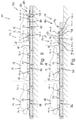
- FIG. 3 shows a straight ascending portion of the rail system of the plant according to FIGS. 1 and 2 , with a trolley according to a second illustrative embodiment
- FIG. 4 shows a section perpendicular to the carrier rail along the sectional line IV-IV in FIG. 3 ;
- FIG. 5 shows a shorter ascending portion of the rail system of the plant, with the trolley according to FIGS. 1 and 2 ;
- FIG. 6 shows a portion of the carrier rail, with a trolley according to a third illustrative embodiment
- FIG. 7 shows a portion of the carrier rail, with a trolley according to a fourth illustrative embodiment
- FIG. 8 shows a perspective view of the portion of the carrier rail, with the trolley according to FIG. 7 without vehicle bodies;
- FIG. 9 shows a schematic layout view of a rail system of a plant for the transportation of workpieces.
- FIGS. 1 and 2 a plant for the transportation of workpieces 12 is denoted by 10 .
- the workpieces 12 are transported on trolleys 14 , which are moved on a rail system 16 .
- the trolleys are denoted by 14 . 1 , 14 . 2 , 14 . 3 and 14 . 4 .
- the workpieces 12 Serving below as an example of workpieces 12 to be transported are vehicle bodies 18 ; however, the workpieces 12 can also be constituted by other workpieces and, in particular, by add-on parts or mount-on parts of vehicle bodies 18 , such as bumpers, side mirrors or the like. Where appropriate, smaller workpieces 12 can be disposed on a workpiece carrier (not specifically shown), which is then transported by the trolley 14 .
- FIGS. 1 and 2 Of the rail system 16 of the plant 10 is shown, in FIGS. 1 and 2 , only a horizontally running portion 20 of a carrier rail 22 , on which latter the trolley 14 . 1 travels and which, in a manner which is known per se, is configured as an I-profile and is anchored to the ground.
- the thus ground-fixed carrier rail 22 is single-track.
- a multitrack, in particular two-track, rail system 16 can also be present.
- the conveying plant 10 can also be an overhead conveyor system, as, in terms of its basic principle, is known per se.
- the trolley 14 . 1 comprises a fastening device 24 , to which a vehicle body 18 or an appropriate workpiece carrier for workpieces 12 can be fastened.
- the fastening device 24 is designed to receive vehicle bodies 18 .
- the fastening device 24 comprises a mounting profile 26 with bearing bolts 28 , of which respectively only one bears a reference symbol and which, in a manner which is known per se, cooperate with mating elements on the vehicle body 18 , so that the vehicle body 18 can be fixed to the fastening device 24 .
- the fastening device 24 can also have several sets of such bearing bolts 28 , which are matched to different vehicle bodies 18 having different dimensions and designs, so that the fastening device 28 can be flexibly used for different vehicle body types.
- the fastening device 24 thus directly receives a vehicle body 18 .
- the vehicle body 18 is fastened in a manner which is known per se to a so-called skid, which is then, together with the vehicle body 18 , fitted to the fastening device 24 .
- the trolley 14 . 1 comprises a trolley chassis 30 , which runs down on the carrier rail 22 and supports the fastening device 24 .
- the trolley chassis 30 comprises a leading unit 34 , which runs ahead in the transport direction 32 , and a trailing unit 36 , which runs behind in the transport direction 32 .
- the transport direction 32 is merely indicated in FIG. 2 by an arrow and, in FIGS. 1 to 3 and 5 to 8 , shall always point to the right.
- the leading unit 34 and the trailing unit 36 are respectively coupled via a coupling joint 38 or 40 with the fastening device and support this between them, so that the trolley 14 . 1 is capable of also passing through curved portions of the carrier rail 22 .
- the leading unit 34 and the trailing unit 36 are broadly structurally identical, wherein individual parts and components are positioned on a straight portion of the carrier rail 22 in mirrored arrangement relative to a plane perpendicular to the transport direction 32 .
- Mutually corresponding parts and components of the leading unit 34 and the trailing unit 36 bear the same reference symbols with the indices “0.1” or “0.2”.
- the leading unit 34 forms a chassis unit 42 . 1
- the trailing unit 36 forms a chassis unit 42 . 2 of the trolley chassis 30 of the trolley 14 . 1 .
- the leading unit 34 supports a drive roller 44 . 1 , which rolls on a drive running surface 46 of the carrier rail 22 and is driven by means of a drive motor 48 . 1 , which is carried along by the leading unit 34 .
- the drive running surface 46 of the carrier rail 22 is the surface on the top side of the I-profile and accordingly runs in horizontal portions of the carrier rail likewise horizontally.
- the drive running surface 46 can also, for example, run vertically; in this case, the drive roller 40 . 1 presses as a friction wheel laterally against the carrier rail 22 .
- the chassis unit 42 . 1 of the leading unit 34 supports at a distance from the drive roller 40 . 1 a passive supporting roller 50 . 1 , which likewise rolls on the drive running surface 46 of the carrier rail 22 .
- the chassis unit 42 . 1 of the leading unit 34 supports a plurality of lateral guide rollers 52 . 1 , of which only two bear a reference symbol and which from both sides bear against the carrier rail 22 and so, in a manner which is known per se, prevent the leading unit 34 from tilting to the side.
- the leading unit 34 comprises a drive frame 54 . 1 , which supports the drive roller 40 . 1 with the drive motor 48 . 1 and, with respect to both sides of the carrier rail 22 , in each case four guide rollers 52 . 1 .
- the drive frame 54 . 1 is connected via a supporting crossbeam 56 . 1 articulately to a supporting frame 58 . 1 , which, for its part, supports the supporting roller 50 . 1 and likewise supports, with respect to both sides of the carrier rail 22 , in each case four guide rollers 52 . 1 .
- the articulated connection of the drive frame 54 . 1 to the supporting frame 58 . 1 is realized again via coupling joints, which enable passage through curved portions of the carrier rail 22 and correspond to the coupling joints 38 , 40 , yet are not specifically provided with a reference symbol.
- both the leading unit 34 and the trailing unit 36 respectively support a drive roller 44 . 1 or 44 . 2 , as well as the respectively associated drive motor 48 . 1 , 48 . 2 .
- a drive roller 44 . 1 with drive motor 48 . 1 is present only on the leading unit 34 .
- the trolley chassis 30 of the trolley 14 . 1 in any event supports at least one drive roller and carries along with it the drive motor of said drive roller.
- the trolley 14 . 1 For the power supply to the drive motors 48 . 1 and 48 . 2 of the leading unit 34 and the trailing unit 36 , the trolley 14 . 1 carries along with it an autonomous power supply device 60 .
- an autonomous power supply device 60 By this should be understood a power supply device which ensures the power supply to the drive motors 48 . 1 , 48 . 2 during running operation, i.e. during the movement of the trolley 14 . 1 , independently from external power sources.
- the power supply device is designed with rechargeable energy stores 62 having at least one energy store unit 64 .
- an energy store unit 64 for the respective drive motor 48 . 1 , 48 . 2 is here present.
- a rechargeable energy store unit 64 for electrical energy can be provided in the form of an accumulator or a capacitor. In the event of a modification (not specifically shown), just a single energy store unit can also be provided for both drive motors 48 . 1 , 48 . 2 .
- compressed-gas stores can also be present as the power source for compressed-gas drives.
- the trailing unit 36 also bears a control device 66 , by means of which the drive motors 48 . 1 , 48 . 2 are controlled and synchronized.
- the control device 66 communicates with a central control unit (not specifically shown) of the plant 10 .
- the trolley 14 . 1 by virtue of the articulated connection of the fastening device 24 to the leading unit 34 and the trailing unit 36 , is curved.
- the trolley 14 . 1 must also surmount inclined portions, i.e. ascending portions or descending portions, of the carrier rail 22 .
- inclined portions of this kind difficulties can arise if the contact pressure of the drive rollers 48 . 1 , 48 . 2 onto the drive running surface 46 of the carrier rail 22 is insufficient to prevent spinning of the drive rollers 48 . 1 , 48 . 2 in ascending portions or slippage of the trolley 14 . 1 in descending portions.
- a modified trolley 14 . 2 therefore comprises an additional inclination drive 68 , which comes into play only in inclined portions of the carrier rail 22 .
- FIG. 3 shows as an example of an inclined portion of the carrier rail 22 an ascending portion 70 , in which this trolley 14 . 2 is found.
- the inclination drive 68 for each drive roller 44 . 1 , 44 . 2 comprises a gearwheel 72 , which is coupled by means of a shaft coaxially, and in a rotationally secure manner, with the respective drive roller 44 . 1 or 44 . 2 and thus, upon a rotation of the drive roller 44 . 1 , 44 . 2 , jointly rotates.
- the supporting frame 58 with its parts is not shown and not all components are provided with reference symbols.
- a gear rack 76 In addition to the carrier rail 22 , extending along the ascending portion 70 is a gear rack 76 , in which the gearwheel 72 engages when the trolley 14 . 2 reaches the ascending portion 70 .
- the equivalent applies to a descending portion (not specifically shown here) of the carrier rail 22 .
- the arrangement of the gear rack 76 is such that the load is dissipated via the drive rollers 44 . 1 , 44 . 2 and the propulsion or braking forces are absorbed via the gear rack 76 .
- a chain in which the gearwheel 72 can engage, can also be present.
- the coupling joints 38 , 40 between the fastening device 24 and the leading unit 34 or trailing unit 36 must also enable pivoting of the mutually connected components about a horizontal pivot axis which runs perpendicular to the transport direction 32 .
- FIG. 5 in which an ascending portion 78 of the carrier rail 22 is illustrated, which ascending portion is sufficiently short that the leading unit 34 or the trailing unit 36 is always found on one of two horizontal portions 20 which run at different height levels and are connected to each other via the ascending portion 78 .
- the inclination drive 70 can possibly be dispensed with, since the reliable propulsion of the trolley is always ensured by the chassis unit 42 . 1 , 42 . 2 , which is found in one of the horizontal portions 20 of the carrier rail 22 ; in FIG. 5 , therefore, the trolley 14 . 1 is shown again.
- FIG. 6 a modified trolley 14 . 3 having a trolley chassis 80 comprising as the drive unit 82 a drivable transport unit 84 , and also a plurality of passive transport units 86 , which latter are releasably coupled via articulated couplings 88 , so that the trolley 14 . 3 is configured as a transport train 90 .
- the drivable transport unit 84 and the passive transport units 86 respectively carry along with them a fastening device 24 .
- the drivable transport unit 84 here comprises the chassis units 42 . 1 , 42 . 2 with drive rollers 44 . 1 , 44 . 2 and drive motors 48 . 1 , 48 . 2 and thus corresponds to the trolley chassis 30 of the trolleys 14 . 1 , 14 . 2 according to FIGS. 1 to 5 ; consequently, the drivable transport unit 84 also carries along with it the power supply device 60 .
- the passive transport units 86 Following behind the drivable transport unit 84 in the transport direction 32 are the passive transport units 86 , which are towed by the drivable transport unit 84 .
- the passive transport units 86 likewise respectively correspond to the trolley chassis 30 of the trolleys 14 . 1 , 14 . 2 according to FIGS. 1 to 5 , with the difference that, instead of the drive rollers 44 . 1 , 44 . 2 , only passive running rollers 92 . 1 , 92 . 2 are present, and hence no drive motors 48 . 1 , 48 . 2 and no power supply device 60 are provided.
- FIGS. 7 and 8 a once again modified trolley 14 . 4 having a trolley chassis 94 which again a drive unit 82 and a plurality of passive transport units 86 .
- the drive unit 82 is not, however, a transport unit with fastening device, but rather a towing trolley 96 without carrying function and having a dedicated chassis unit 98 .
- This is constructed similarly to the leading unit 34 , though there two drive frames 54 . 1 , 54 . 2 , with the respectively associated drive roller 44 . 1 and 44 . 2 and the necessary drive motors 48 . 1 and 48 . 2 , are connected to each other.
- the chassis unit 94 carries along with it a power supply device 60 for its power supply.
- the towing trolley 96 thus comprises no fastening device 24 and can receive no workpiece 12 .
- the rechargeable energy stores 62 can also be carried along not by the drive unit 82 , but rather by one of the passive transport units 86 .
- FIG. 9 now shows in schematic representation a layout of a plant 10 comprising various conveying zones and treatment zones, in which the above-described trolleys 14 . 1 , 14 . 2 , 14 . 3 and 14 . 4 can be used.
- 100 and 102 respectively denote a buffer zone, 104 a dryer, 106 a portion having inclined regions, which in both possible transport directions succeed one another in the form of an ascent and descent.
- 108 a to 108 g are denoted switch points, and by 110 is denoted a rotary switch in order to bridge a track intersection. If the rotary switch 110 is sufficiently large for a trolley 14 . 1 , 14 . 2 , or even for a train-type trolley 14 . 3 , 14 . 4 , a change of direction, for example, can thus also be made at the track intersection.
- the trolleys 14 . 1 , 14 . 2 , 14 . 3 , 14 . 4 enter one behind the other via the switches 108 which are present there.
- the trolleys 14 . 1 and 14 . 2 can enter, since a kind of tilting of the trolleys 14 . 1 , 14 . 2 takes place there on two parallel track sections 114 , 116 .
- the leading unit 34 first passes through, for example, the switch 108 f and pulls onto the track section 114 , the switch 108 f is then switched over, so that the trailing unit 36 makes its way onto the track section 116 , and the trolley 14 . 1 , 14 . 2 , due to the rotary couplings 38 , 40 which are present, can turn diagonally, as is indicated by the position of the vehicle bodies 18 in the buffer zone 102 .
- the carrying trolleys 14 . 3 and 14 . 4 are used. In this way, only a small number of drive components are exposed to the hot dryer atmosphere.
- the towing trolley 96 which is present there to transfer the passive transport units 86 to an alternative conveying method, such as, for instance, a conveyor chain or the like, by means of which the passive transport units 86 are then conveyed through the dryer 104 .
- the towing trolley 96 can then be led past the dryer 104 on a track section 118 and, at the dryer outlet, can reclaim possession of the passive transport units 96 leaving the dryer 104 .
- By 120 is denoted, by way of example, a charging station, into which the chassis of the trolleys 14 . 1 , 14 . 2 , 14 . 3 or 14 . 4 , which chassis are fitted with the rechargeable energy stores 62 , enter and can be charged.
- charging stations 120 are present on a side track, which can likewise be reached via switches.
- Such charging stations 120 can be visited specifically for a charging process when the charging state of the energy stores 62 of the trolleys 14 . 1 , 14 . 2 , 14 . 3 or 14 . 4 reaches a lower threshold value.
- Charging stations 120 can also be formed at loading or unloading stations at which the trolleys 14 . 1 , 14 . 2 , 14 . 3 or 14 . 4 are loaded or unloaded. In this way, the dwell time of the trolleys 14 . 1 , 14 . 2 , 14 . 3 or 14 . 4 can be utilized for a charging operation.
- the plant 10 makes do with a relatively small number of charging stations 120 . In the case of accumulators as the energy stores 62 , this can be implemented well.
- the capacities of the energy stores 62 and the distances between two charging stations 120 can be mutually coordinated such that the charged energy stores 62 can only receive so much energy that the trolleys 14 . 1 , 14 . 2 , 14 . 3 or 14 . 4 can bridge the path between two charging stations 120 .
- the energy stores 62 capacitors, in particular, can be considered in such a case.
- the carrier rail 22 can comprise charging portions 122 which are fitted with a busbar, from which, via a contact shoe or contactlessly, power can be received by the trolleys 14 . 1 , 14 . 2 , 14 . 3 or 14 . 4 .
- the trolleys 14 . 1 , 14 . 2 , 14 . 3 or 14 . 4 carry with them appropriate current collectors.
- the portion between the switches 108 a and 108 g is labeled as the charging portion 122 .
Abstract
Description
- a) a trolley chassis, which supports at least one drive roller that is rollable on a drive running surface of the carrier rail and is drivable by means of a drive motor, which latter is carried along by the trolley chassis;
- b) at least one fastening device for at least one workpiece.
- a) a rail system, which comprises at least one carrier rail;
- b) at least one trolley movable in a transport direction on the carrier rail.
- c) the trolley carries along with it an autonomous power supply device, by means of which the drive motor can be supplied with power.
- a) the leading unit bears a drive roller and a drive motor;
- and/or
- b) the trailing unit bears a drive roller and a drive motor;
- wherein
- c) the leading unit and/or the trailing unit bear(s) at least one rechargeable energy store.
Claims (10)
Applications Claiming Priority (3)
| Application Number | Priority Date | Filing Date | Title |
|---|---|---|---|
| DE102015003736.6A DE102015003736A1 (en) | 2015-03-21 | 2015-03-21 | Transport trolley and equipment for transporting objects |
| DE102015003736.6 | 2015-03-21 | ||
| PCT/EP2016/000322 WO2016150543A1 (en) | 2015-03-21 | 2016-02-25 | Transport carriage and system for transporting objects |
Publications (2)
| Publication Number | Publication Date |
|---|---|
| US20180099681A1 US20180099681A1 (en) | 2018-04-12 |
| US11279382B2 true US11279382B2 (en) | 2022-03-22 |
Family
ID=55446734
Family Applications (1)
| Application Number | Title | Priority Date | Filing Date |
|---|---|---|---|
| US15/559,729 Active 2036-06-21 US11279382B2 (en) | 2015-03-21 | 2016-02-25 | Transport carriage and system for transporting objects |
Country Status (5)
| Country | Link |
|---|---|
| US (1) | US11279382B2 (en) |
| EP (1) | EP3274236A1 (en) |
| CN (1) | CN107428343A (en) |
| DE (1) | DE102015003736A1 (en) |
| WO (1) | WO2016150543A1 (en) |
Cited By (1)
| Publication number | Priority date | Publication date | Assignee | Title |
|---|---|---|---|---|
| US11952223B2 (en) | 2018-05-09 | 2024-04-09 | Eisenmann Gmbh | Dip treatment system and method for the dip treatment of articles, in particular vehicle bodies |
Families Citing this family (12)
| Publication number | Priority date | Publication date | Assignee | Title |
|---|---|---|---|---|
| DE102015003736A1 (en) * | 2015-03-21 | 2016-09-22 | Eisenmann Se | Transport trolley and equipment for transporting objects |
| DE102016004484A1 (en) | 2016-04-13 | 2017-10-19 | Eisenmann Se | Process and manufacturing plant for the production of vehicles and surface treatment equipment for the surface treatment of vehicle bodies |
| DE102016119540A1 (en) * | 2016-10-13 | 2018-04-19 | Eisenmann Se | Temperature control device, surface treatment plant, manufacturing plant and process for the production of products |
| PL3609774T3 (en) * | 2017-04-11 | 2021-06-14 | Ebz Systec Gmbh | Conveyor device for an automated production line, component carrier carriage for a conveyor device, and method for operating a conveyor device |
| DE102017118561A1 (en) | 2017-08-15 | 2019-02-21 | Eisenmann Se | Conveying device for conveying workpieces in a surface treatment plant |
| DE202018102002U1 (en) * | 2018-04-12 | 2019-07-15 | Aberu Gmbh | Device for feeding charge carriers and / or trays to and from a loading and / or unloading station |
| DE202018102001U1 (en) * | 2018-04-12 | 2019-07-15 | Aberu Gmbh | Device for moving load carriers, adapters for receiving load carriers and transport trolleys for picking up and transporting load carriers |
| CN108706260A (en) * | 2018-04-19 | 2018-10-26 | 江苏高科物流科技股份有限公司 | A kind of transport vehicle system, transport vehicle and products storage circulation system |
| DE102018109584A1 (en) * | 2018-04-20 | 2019-10-24 | Eisenmann Se | Conveyor with a tram |
| CN108439143A (en) * | 2018-05-20 | 2018-08-24 | 上海力格郎环保科技有限公司 | A kind of automatic transmission lowering means |
| DE102018115485A1 (en) | 2018-06-27 | 2020-01-02 | Eisenmann Se | Conveyor system, mounting rail and production system |
| DE102020134908A1 (en) * | 2020-12-23 | 2022-06-23 | Pentanova Cs Gmbh | Suspension rail system for transporting workpieces |
Citations (40)
| Publication number | Priority date | Publication date | Assignee | Title |
|---|---|---|---|---|
| US601296A (en) * | 1898-03-29 | Of car wheels upon grades | ||
| US1704958A (en) * | 1926-01-11 | 1929-03-12 | Bbc Brown Boveri & Cie | Electric railway system |
| US4776282A (en) * | 1987-03-10 | 1988-10-11 | Tsubakimoto Chain Company | Self-running device for a transporting carrier |
| US4901648A (en) * | 1988-04-15 | 1990-02-20 | Mid-West Conveyor Company, Inc. | Trolley braking method and apparatus for use with conveyors |
| US4944230A (en) * | 1987-08-03 | 1990-07-31 | Daifuku Co., Ltd. | Conveyor apparatus using automotive cart |
| US5165348A (en) * | 1989-07-31 | 1992-11-24 | Nakanishi Metal Works Co., Ltd. | Conveyor having self-propelled carriers and track with pivotal ratchet pawl teeth to ensure smooth transition between friction drive and pinion drive |
| US5174217A (en) * | 1989-01-19 | 1992-12-29 | Nakanishi Metal Works Co., Ltd. | Conveyor having self-propelled carriers with a first motor for high speed driving and a second motor for low speed driving |
| US5235917A (en) * | 1990-10-18 | 1993-08-17 | Mannesmann Aktiengesellschaft | Monorail trolley with u-shape frame extending over, above, and surrounding the rail |
| EP0577917A1 (en) | 1992-06-05 | 1994-01-12 | cfc-Fördersysteme GmbH | Electric overhead conveyor |
| EP0582348A1 (en) | 1992-08-07 | 1994-02-09 | FATA AUTOMATION S.p.A. | Suspended rail conveyance system |
| US5388684A (en) * | 1994-02-22 | 1995-02-14 | Peck Automated Systems, Inc. | Pallet conveyor |
| US5450796A (en) * | 1993-10-20 | 1995-09-19 | Daifuku Co., Ltd. | Transport system with electric rail cars |
| US5901650A (en) * | 1997-10-14 | 1999-05-11 | Honda Of America Mfg., Inc. | Dynamic buffer for conveyor modules |
| US5979334A (en) * | 1995-06-07 | 1999-11-09 | Autran Corp. | System for automated transport of automobile platforms, passenger cabins and other loads |
| US6129025A (en) * | 1995-07-04 | 2000-10-10 | Minakami; Hiroyuki | Traffic/transportation system |
| US6178891B1 (en) * | 1998-01-16 | 2001-01-30 | Mannesmann Aktiengesellschaft | Suspension monorail with climbing trolley |
| US6192803B1 (en) * | 1996-08-02 | 2001-02-27 | Daifuku Co., Ltd. | Travel control system for transport movers |
| US6305296B1 (en) * | 1997-12-31 | 2001-10-23 | Southem Engineering Pty Ltd | Power pack trolley and captivation system |
| US6494304B1 (en) * | 2000-08-15 | 2002-12-17 | Jervis B. Webb Company | Production operation with power and free pallet conveyor |
| US6595141B2 (en) * | 1998-04-09 | 2003-07-22 | Nakanishi Metal Works Co., Ltd | Truck transport apparatus |
| EP1352817A1 (en) | 2003-05-13 | 2003-10-15 | TMS Automotion GmbH | Transport device and method for transporting components |
| US20080148546A1 (en) * | 2006-12-22 | 2008-06-26 | Comau S.P.A | System for assembling, in particular by welding, structures made up of elements of pressed sheet metal, such as motor-vehicle bodies or subassemblies thereof |
| US20080251354A1 (en) * | 2007-04-13 | 2008-10-16 | Eisenmann Anlagenbau Gmbh & Co. Kg | Skid for supporting an object, and transfer station, drive unit, drive system and conveyor installation for such skids |
| WO2009059362A1 (en) | 2007-11-06 | 2009-05-14 | Ubeauti Pty Ltd | A monorail rapid transit system |
| DE102008032151A1 (en) | 2008-07-08 | 2010-01-21 | Eisenmann Anlagenbau Gmbh & Co. Kg | Conveyor, particularly electro-rail conveyor system for use in industrial plants for transporting work pieces, has electro-track railway which consists of load- and guide-rail and load bearing wagon that carries work pieces |
| US7798068B2 (en) * | 2008-02-05 | 2010-09-21 | Daifuku Co., Ltd | Friction drive trolley conveyor |
| US20110017132A1 (en) * | 2008-02-21 | 2011-01-27 | Eisenmann Anlagenbau Gmbh & Co. Kg | Overhead Conveyor System and Dip Coating Line Comprising Said System |
| DE102010041894A1 (en) | 2010-10-01 | 2012-04-05 | Dürr Systems GmbH | Drive unit for conveyor, is provided with drive motors for movement of load bearing unit in guide with supporting surface, where drive motor is incorporated in trolleys guided in guide |
| CN102490727A (en) | 2011-12-06 | 2012-06-13 | 华南农业大学 | Electric mountain orchard single-rail transporting machine |
| JP2012121652A (en) | 2010-12-07 | 2012-06-28 | Daifuku Co Ltd | Carriage type transport device using tractor |
| US20130206059A1 (en) * | 2010-09-10 | 2013-08-15 | Eisenmann Ag | Dip coating system |
| US9394110B2 (en) * | 2011-05-31 | 2016-07-19 | Eisenmann Ag | Apparatus for conveying and plant for surface-treating articles |
| US9533830B2 (en) * | 2014-09-30 | 2017-01-03 | Liebherr-Verzahntechnik Gmbh | Workpiece carrier |
| US9688478B2 (en) * | 2010-09-10 | 2017-06-27 | Eisenmann Se | Conveyor unit and conveyor system for conveying vehicle bodies and plant for machining vehicle bodies |
| US20170282937A1 (en) * | 2016-04-04 | 2017-10-05 | Sewoong Machinery Co., Ltd. | Overhead conveyor |
| US20180099681A1 (en) * | 2015-03-21 | 2018-04-12 | Eisenmann Se | Transport carriage and system for transporting objects |
| US20180120028A1 (en) * | 2015-05-09 | 2018-05-03 | Eisenmann Se | Temperature control device for controlling the temperature of workpieces |
| US20180265151A1 (en) * | 2015-09-18 | 2018-09-20 | Eisenmann Se | Conveying apparatus for conveying transporting structures |
| US10124958B2 (en) * | 2014-08-16 | 2018-11-13 | Eisenmann Se | Conveyor device for transporation structures |
| US10526030B2 (en) * | 2016-05-10 | 2020-01-07 | The Hi-Tech Robotic Systemz Ltd. | Climb structure for a robot |
Family Cites Families (3)
| Publication number | Priority date | Publication date | Assignee | Title |
|---|---|---|---|---|
| CN102730010A (en) * | 2011-04-12 | 2012-10-17 | 中国科学院沈阳自动化研究所 | Straddle type monorail travelling mechanism |
| EP2792394B1 (en) * | 2013-04-16 | 2016-07-27 | Jörg Beutler | Interactive speed control |
| CN104309608B (en) * | 2014-10-21 | 2016-08-24 | 常州科研试制中心有限公司 | Self-driving formula wire saws monorail crane system |
-
2015
- 2015-03-21 DE DE102015003736.6A patent/DE102015003736A1/en active Pending
-
2016
- 2016-02-25 CN CN201680017177.XA patent/CN107428343A/en active Pending
- 2016-02-25 US US15/559,729 patent/US11279382B2/en active Active
- 2016-02-25 WO PCT/EP2016/000322 patent/WO2016150543A1/en active Application Filing
- 2016-02-25 EP EP16706975.6A patent/EP3274236A1/en active Pending
Patent Citations (41)
| Publication number | Priority date | Publication date | Assignee | Title |
|---|---|---|---|---|
| US601296A (en) * | 1898-03-29 | Of car wheels upon grades | ||
| US1704958A (en) * | 1926-01-11 | 1929-03-12 | Bbc Brown Boveri & Cie | Electric railway system |
| US4776282A (en) * | 1987-03-10 | 1988-10-11 | Tsubakimoto Chain Company | Self-running device for a transporting carrier |
| US4944230A (en) * | 1987-08-03 | 1990-07-31 | Daifuku Co., Ltd. | Conveyor apparatus using automotive cart |
| US4901648A (en) * | 1988-04-15 | 1990-02-20 | Mid-West Conveyor Company, Inc. | Trolley braking method and apparatus for use with conveyors |
| US5174217A (en) * | 1989-01-19 | 1992-12-29 | Nakanishi Metal Works Co., Ltd. | Conveyor having self-propelled carriers with a first motor for high speed driving and a second motor for low speed driving |
| US5165348A (en) * | 1989-07-31 | 1992-11-24 | Nakanishi Metal Works Co., Ltd. | Conveyor having self-propelled carriers and track with pivotal ratchet pawl teeth to ensure smooth transition between friction drive and pinion drive |
| US5235917A (en) * | 1990-10-18 | 1993-08-17 | Mannesmann Aktiengesellschaft | Monorail trolley with u-shape frame extending over, above, and surrounding the rail |
| EP0577917A1 (en) | 1992-06-05 | 1994-01-12 | cfc-Fördersysteme GmbH | Electric overhead conveyor |
| EP0582348A1 (en) | 1992-08-07 | 1994-02-09 | FATA AUTOMATION S.p.A. | Suspended rail conveyance system |
| US5450796A (en) * | 1993-10-20 | 1995-09-19 | Daifuku Co., Ltd. | Transport system with electric rail cars |
| US5388684A (en) * | 1994-02-22 | 1995-02-14 | Peck Automated Systems, Inc. | Pallet conveyor |
| US5979334A (en) * | 1995-06-07 | 1999-11-09 | Autran Corp. | System for automated transport of automobile platforms, passenger cabins and other loads |
| US6129025A (en) * | 1995-07-04 | 2000-10-10 | Minakami; Hiroyuki | Traffic/transportation system |
| US6192803B1 (en) * | 1996-08-02 | 2001-02-27 | Daifuku Co., Ltd. | Travel control system for transport movers |
| US5901650A (en) * | 1997-10-14 | 1999-05-11 | Honda Of America Mfg., Inc. | Dynamic buffer for conveyor modules |
| US6305296B1 (en) * | 1997-12-31 | 2001-10-23 | Southem Engineering Pty Ltd | Power pack trolley and captivation system |
| US6178891B1 (en) * | 1998-01-16 | 2001-01-30 | Mannesmann Aktiengesellschaft | Suspension monorail with climbing trolley |
| US6595141B2 (en) * | 1998-04-09 | 2003-07-22 | Nakanishi Metal Works Co., Ltd | Truck transport apparatus |
| US6494304B1 (en) * | 2000-08-15 | 2002-12-17 | Jervis B. Webb Company | Production operation with power and free pallet conveyor |
| EP1352817A1 (en) | 2003-05-13 | 2003-10-15 | TMS Automotion GmbH | Transport device and method for transporting components |
| US20080148546A1 (en) * | 2006-12-22 | 2008-06-26 | Comau S.P.A | System for assembling, in particular by welding, structures made up of elements of pressed sheet metal, such as motor-vehicle bodies or subassemblies thereof |
| US20080251354A1 (en) * | 2007-04-13 | 2008-10-16 | Eisenmann Anlagenbau Gmbh & Co. Kg | Skid for supporting an object, and transfer station, drive unit, drive system and conveyor installation for such skids |
| WO2009059362A1 (en) | 2007-11-06 | 2009-05-14 | Ubeauti Pty Ltd | A monorail rapid transit system |
| US7798068B2 (en) * | 2008-02-05 | 2010-09-21 | Daifuku Co., Ltd | Friction drive trolley conveyor |
| US20110017132A1 (en) * | 2008-02-21 | 2011-01-27 | Eisenmann Anlagenbau Gmbh & Co. Kg | Overhead Conveyor System and Dip Coating Line Comprising Said System |
| US10106337B2 (en) * | 2008-02-21 | 2018-10-23 | Eisenmann Se | Overhead conveyor system and dip coating line comprising said system |
| DE102008032151A1 (en) | 2008-07-08 | 2010-01-21 | Eisenmann Anlagenbau Gmbh & Co. Kg | Conveyor, particularly electro-rail conveyor system for use in industrial plants for transporting work pieces, has electro-track railway which consists of load- and guide-rail and load bearing wagon that carries work pieces |
| US9688478B2 (en) * | 2010-09-10 | 2017-06-27 | Eisenmann Se | Conveyor unit and conveyor system for conveying vehicle bodies and plant for machining vehicle bodies |
| US20130206059A1 (en) * | 2010-09-10 | 2013-08-15 | Eisenmann Ag | Dip coating system |
| DE102010041894A1 (en) | 2010-10-01 | 2012-04-05 | Dürr Systems GmbH | Drive unit for conveyor, is provided with drive motors for movement of load bearing unit in guide with supporting surface, where drive motor is incorporated in trolleys guided in guide |
| JP2012121652A (en) | 2010-12-07 | 2012-06-28 | Daifuku Co Ltd | Carriage type transport device using tractor |
| US9394110B2 (en) * | 2011-05-31 | 2016-07-19 | Eisenmann Ag | Apparatus for conveying and plant for surface-treating articles |
| CN102490727A (en) | 2011-12-06 | 2012-06-13 | 华南农业大学 | Electric mountain orchard single-rail transporting machine |
| US10124958B2 (en) * | 2014-08-16 | 2018-11-13 | Eisenmann Se | Conveyor device for transporation structures |
| US9533830B2 (en) * | 2014-09-30 | 2017-01-03 | Liebherr-Verzahntechnik Gmbh | Workpiece carrier |
| US20180099681A1 (en) * | 2015-03-21 | 2018-04-12 | Eisenmann Se | Transport carriage and system for transporting objects |
| US20180120028A1 (en) * | 2015-05-09 | 2018-05-03 | Eisenmann Se | Temperature control device for controlling the temperature of workpieces |
| US20180265151A1 (en) * | 2015-09-18 | 2018-09-20 | Eisenmann Se | Conveying apparatus for conveying transporting structures |
| US20170282937A1 (en) * | 2016-04-04 | 2017-10-05 | Sewoong Machinery Co., Ltd. | Overhead conveyor |
| US10526030B2 (en) * | 2016-05-10 | 2020-01-07 | The Hi-Tech Robotic Systemz Ltd. | Climb structure for a robot |
Cited By (1)
| Publication number | Priority date | Publication date | Assignee | Title |
|---|---|---|---|---|
| US11952223B2 (en) | 2018-05-09 | 2024-04-09 | Eisenmann Gmbh | Dip treatment system and method for the dip treatment of articles, in particular vehicle bodies |
Also Published As
| Publication number | Publication date |
|---|---|
| DE102015003736A1 (en) | 2016-09-22 |
| US20180099681A1 (en) | 2018-04-12 |
| WO2016150543A1 (en) | 2016-09-29 |
| EP3274236A1 (en) | 2018-01-31 |
| CN107428343A (en) | 2017-12-01 |
Similar Documents
| Publication | Publication Date | Title |
|---|---|---|
| US11279382B2 (en) | Transport carriage and system for transporting objects | |
| US10359234B2 (en) | Temperature control device for controlling the temperature of workpieces | |
| US11167305B2 (en) | Method and production system for producing vehicles, and surface treatment system for treating the surface of vehicle bodies | |
| US8474594B2 (en) | Drive unit, drive system and conveyor installation for skid supporting an object | |
| US9688478B2 (en) | Conveyor unit and conveyor system for conveying vehicle bodies and plant for machining vehicle bodies | |
| CN101200185B (en) | Device for storing transportation means of aerial cableway | |
| CN103935694A (en) | Heavy type suspension hinge conveying machine and conveying system | |
| US10919591B2 (en) | Transport system | |
| CN108045826A (en) | A kind of Material Sorting system and Material Sorting method | |
| CN111492109A (en) | Sleeper transport vehicle | |
| US20110005902A1 (en) | Roller conveyor and a roller path system therefor | |
| EP1044148B1 (en) | A conveyor | |
| CN207416828U (en) | A kind of pipeline | |
| CN210028984U (en) | Electric power and free vehicle group conveyor | |
| CN207617723U (en) | A kind of stream carrier vehicle with door type structure | |
| US20190003305A1 (en) | Tunnel boring machine backup train comprising means for conveying an arch segment | |
| KR20190006529A (en) | Vehicles for transport systems and transport systems | |
| CN109835678A (en) | A kind of annular sorting shuttle | |
| CN212221740U (en) | Conveying device for container goods yard | |
| KR101853092B1 (en) | Moving apparatus of switch and crossing for magnetically levitated vehicle having sub motor | |
| CN205471283U (en) | Driven leading wheel | |
| JPH0366041B2 (en) | ||
| CN212981488U (en) | Discrete conveying goods shelf | |
| JPH06239448A (en) | Conveyor equipment using self-traveling truck | |
| CN211894851U (en) | Multipurpose transfer machine capable of being used for transverse movement of shuttle and sledge body |
Legal Events
| Date | Code | Title | Description |
|---|---|---|---|
| FEPP | Fee payment procedure |
Free format text: ENTITY STATUS SET TO UNDISCOUNTED (ORIGINAL EVENT CODE: BIG.); ENTITY STATUS OF PATENT OWNER: LARGE ENTITY |
|
| AS | Assignment |
Owner name: EISENMANN SE, GERMANY Free format text: ASSIGNMENT OF ASSIGNORS INTEREST;ASSIGNORS:RIEGRAF, MARTIN;ROBBIN, JOERG;REEL/FRAME:044149/0875 Effective date: 20171019 |
|
| STPP | Information on status: patent application and granting procedure in general |
Free format text: DOCKETED NEW CASE - READY FOR EXAMINATION |
|
| STPP | Information on status: patent application and granting procedure in general |
Free format text: NON FINAL ACTION MAILED |
|
| STPP | Information on status: patent application and granting procedure in general |
Free format text: FINAL REJECTION MAILED |
|
| STPP | Information on status: patent application and granting procedure in general |
Free format text: NON FINAL ACTION MAILED |
|
| STPP | Information on status: patent application and granting procedure in general |
Free format text: RESPONSE TO NON-FINAL OFFICE ACTION ENTERED AND FORWARDED TO EXAMINER |
|
| STPP | Information on status: patent application and granting procedure in general |
Free format text: FINAL REJECTION MAILED |
|
| AS | Assignment |
Owner name: PENTANOVA CS GMBH, GERMANY Free format text: ASSIGNMENT OF ASSIGNORS INTEREST;ASSIGNOR:EISENMANN SE;REEL/FRAME:055666/0819 Effective date: 20201013 |
|
| STPP | Information on status: patent application and granting procedure in general |
Free format text: DOCKETED NEW CASE - READY FOR EXAMINATION |
|
| STPP | Information on status: patent application and granting procedure in general |
Free format text: NON FINAL ACTION MAILED |
|
| STPP | Information on status: patent application and granting procedure in general |
Free format text: RESPONSE TO NON-FINAL OFFICE ACTION ENTERED AND FORWARDED TO EXAMINER |
|
| STPP | Information on status: patent application and granting procedure in general |
Free format text: NOTICE OF ALLOWANCE MAILED -- APPLICATION RECEIVED IN OFFICE OF PUBLICATIONS |
|
| STCF | Information on status: patent grant |
Free format text: PATENTED CASE |