EP1044148B1 - A conveyor - Google Patents
A conveyor Download PDFInfo
- Publication number
- EP1044148B1 EP1044148B1 EP98963396A EP98963396A EP1044148B1 EP 1044148 B1 EP1044148 B1 EP 1044148B1 EP 98963396 A EP98963396 A EP 98963396A EP 98963396 A EP98963396 A EP 98963396A EP 1044148 B1 EP1044148 B1 EP 1044148B1
- Authority
- EP
- European Patent Office
- Prior art keywords
- conveyor
- guiding means
- conveyor unit
- guide member
- main track
- Prior art date
- Legal status (The legal status is an assumption and is not a legal conclusion. Google has not performed a legal analysis and makes no representation as to the accuracy of the status listed.)
- Expired - Lifetime
Links
Images


Classifications
-
- B—PERFORMING OPERATIONS; TRANSPORTING
- B65—CONVEYING; PACKING; STORING; HANDLING THIN OR FILAMENTARY MATERIAL
- B65G—TRANSPORT OR STORAGE DEVICES, e.g. CONVEYORS FOR LOADING OR TIPPING, SHOP CONVEYOR SYSTEMS OR PNEUMATIC TUBE CONVEYORS
- B65G17/00—Conveyors having an endless traction element, e.g. a chain, transmitting movement to a continuous or substantially-continuous load-carrying surface or to a series of individual load-carriers; Endless-chain conveyors in which the chains form the load-carrying surface
- B65G17/12—Conveyors having an endless traction element, e.g. a chain, transmitting movement to a continuous or substantially-continuous load-carrying surface or to a series of individual load-carriers; Endless-chain conveyors in which the chains form the load-carrying surface comprising a series of individual load-carriers fixed, or normally fixed, relative to traction element
- B65G17/123—Conveyors having an endless traction element, e.g. a chain, transmitting movement to a continuous or substantially-continuous load-carrying surface or to a series of individual load-carriers; Endless-chain conveyors in which the chains form the load-carrying surface comprising a series of individual load-carriers fixed, or normally fixed, relative to traction element arranged to keep the load-carriers horizontally during at least a part of the conveyor run
-
- B—PERFORMING OPERATIONS; TRANSPORTING
- B65—CONVEYING; PACKING; STORING; HANDLING THIN OR FILAMENTARY MATERIAL
- B65G—TRANSPORT OR STORAGE DEVICES, e.g. CONVEYORS FOR LOADING OR TIPPING, SHOP CONVEYOR SYSTEMS OR PNEUMATIC TUBE CONVEYORS
- B65G2201/00—Indexing codes relating to handling devices, e.g. conveyors, characterised by the type of product or load being conveyed or handled
- B65G2201/02—Articles
- B65G2201/0288—Signatures, i.e. sections of printed magazines, papers or books
-
- B—PERFORMING OPERATIONS; TRANSPORTING
- B65—CONVEYING; PACKING; STORING; HANDLING THIN OR FILAMENTARY MATERIAL
- B65G—TRANSPORT OR STORAGE DEVICES, e.g. CONVEYORS FOR LOADING OR TIPPING, SHOP CONVEYOR SYSTEMS OR PNEUMATIC TUBE CONVEYORS
- B65G2207/00—Indexing codes relating to constructional details, configuration and additional features of a handling device, e.g. Conveyors
- B65G2207/18—Crossing conveyors
Definitions
- the present invention relates to a conveyor for transporting articles such as letters, mail parcels, CDs, and other types of articles, in particular articles of a relatively light weight such as, e.g., of a maximum weight of about 8 kg, in particular a maximum weight of about 5 kg (although it will be understood that the principles of the invention can be utilised also in connection with articles of a higher weight than about 8 kg).
- the invention relates to a conveyor which allows a high degree of adaptability to requirements or constraints with respect to the space it can occupy and the path along which the conveyor units can travel.
- Conveyors for letters, mail parcels, CDs, videotapes, books and other relatively light , articles should be designed so that they can relatively easily be installed and operated under widely varying space conditions, both with regard to the amount of space the conveyors can occupy and with respect to the three-dimensional configuration of the space available.
- Examples of conveyors in which the conveyor units are capable of travelling along a curving path extending between different vertical positions appear from AT Patent No. 347.333 and Swedish published patent application No. 92026749.
- the pre-characterising part of claim 1 is based on DE 2148778.
- the present invention seeks to provide an improved conveyor, as discussed below.
- the present invention relates to such conveyors that are highly flexible with respect to their installation and operation and which permit the conveyor units thereof to follow paths in any desired direction; which can be installed and operated in a space comprising more than one floor and/or on walls; in which a loading station can be installed directly above or directly under a discharge station, and/or loading stations or discharge stations can be installed directly above each other; and which can be made economically and yet deliver a highly efficient and flawless operation.
- the conveyor according to the invention comprises
- the first and the second main track sections will normally be horizontally oriented.
- the endless carrier means is normally, and in most cases preferably, a chain, but also other means, such as, e.g., a toothed belt or an endless series of connected carriages, which are capable of carrying the conveyor units in the manner disclosed herein are contemplated.
- each conveyor unit is preferably horizontal or substantially horizontal. In most cases, it will also be preferred that the main axis of each conveyor is substantially perpendicular to the transport direction.
- each of the conveyor units with its article-supporting member, e.g. a cross-belt unit, extending away from the vertical plane of the carrier means permits a design where sections of the track can be mounted in an open space or on a wall as desired.
- Curvature of the track in a vertical direction e.g. a vertical loop connecting two substantially straight track sections and reverting the direction of the track, can be compensated for by the conveyor units pivoting around their main axis, the maintaining or substantially maintaining the article-supporting member, e.g. a cross-belt unit, in its position relative to the horizontal plane, normally a position where the article-supporting surface of the member is horizontal, being achieved through the engagement of the guide member with the first guiding means.
- the first guiding means will extend substantially parallel to at least a part of the main track.
- the first guiding means may in itself be a track with which the first guide member of each carrier unit engages, or it may comprise, e.g., protrusions such as pins or bars, which move along a path which normally extends substantially parallel to at least a part of the main track and which engage with the first guide member of each conveyor unit.
- Torque-absorbing means may preferably be arranged in substantially the same vertical plane as the carrier means. This means that the torque-absorbing means will normally not extend further from the main track, normally in the direction opposite to the article-supporting member, than four times the breadth of the main track, preferably not further than three times and more preferred not further than twice the breadth of the main track.
- the torque-absorbing means could be a relatively heavy counterweight placed on the opposite side of the carrier means relative to the article-supporting member of the conveyor unit; the counterweight could be adjustable to compensate for variations of the loading on the article-supporting member, the compensation being performed manually or preferably automatically, e.g. in response to a sensor detecting the angle of the article-supporting member of the conveyor unit relative to the horizontal plane and producing an output signal indicating the detected angle
- the torque absorbing means preferably constitutes an integrated part of the carrier means, such as, for each conveyor unit, at least one wheel or low friction slide part/slide member/slide shoe connected to or forming part of the carrier means and engaging with a track part, preferably a part of the main track, and co-operating with another engaging member, e.g. another wheel on a common axle, in such a manner that the torque is absorbed while permitting free movement of the total arrangement in the transport direction.
- An embodiment of such a torque-absorbing means is shown in the figures. It will be understood that in principle, to be comparable to the counterweight example above, such a torque-absorbing means consists of the combination of e.g. the wheel pair on the common axle and the track parts with which each wheel engages, and such a combination and similar combinations are covered by the term "torque absorbing means" herein.
- the conveyor according to the invention may further comprise a second guiding means that extends substantially parallel to at least a substantial part of the main track, each conveyor unit comprises a second guide member adapted to co-operate with said second guiding means when the conveyor unit moves along at least a substantial part of straight sections of said main track, the second guiding means and the second guide members when co-operating are adapted to counteract or prevent the article-supporting member from tilting from its position relative to the horizontal plane.
- the first and second guide members of each conveyor unit and the first and second guiding means are preferably adapted so that the first guide member co-operates with the first guiding means when the conveyor unit enters the curving main track section and before the second guide member disengages with the second guiding means and so that the second guide member co-operates with the second guiding means when the conveyor unit leaves the curving main track section and before the first guide member disengages with the first guiding means.
- the function of the second guide member can be performed by the first guide member so that both the first and the second guide members are constituted by one and the same guide member.
- the second guide member and the second guiding means are preferably arranged in substantially the same vertical plane as the carrier means or in a vertical plane closely adjacent to said plane.
- the first guide member of at least one conveyor unit and preferably of all the conveyor units may comprise two wheels arranged in substantially the same vertical plane with a spacing between them and arranged pivotally on a bar which is arranged on the conveyor unit such that said bar is allowed to pivot about a third axis that extends substantially midway between and substantially parallel to the axes about which said two wheels are allowed to pivot, said third axis being substantially parallel to the first axis of the conveyor unit, the first, second and third axes of the conveyor unit being arranged with a spacing between each axis, and the first guiding means comprising a track protruding from a vertical plane and comprising two parallel surfaces with which said two wheels engage with said track in between said two wheels when the first guide member engages with the first guiding means
- each conveyor unit comprises a third guide member adapted to co-operate with said third guiding means, the second and third guiding means being adapted so that the third guide member co-operates with the third guiding means when the conveyor unit enters the curving main track section and before the second guide member disengages with the second guiding means and so that the second guide member co-operates with the second guiding means when the conveyor unit leaves the curving main track section and before the third guide member disengages with the third guiding means.
- the conveyor may comprise a fourth guiding means arranged in substantially in the same vertical plane as the first guiding means, each conveyor unit comprises a fourth guide member adapted to co-operate with said fourth guiding means, the first, third and fourth guiding members of each conveyor unit forming an obtuse-angled triangle in a vertical plane.
- the conveyor comprises first, second and third guide members of each conveyor unit and first, second and third guiding means being adapted so that the first guide member co-operates with the first guiding means when the conveyor unit enters the curving main track section and before the second guide member disengages with the second guiding means, so that the third guide member co-operates with the third guiding means before the first guide member disengages with the first guiding means when the conveyor unit passes a given position along the curving main track section, and so that the second guide member co-operates with the second guiding means when the conveyor unit leaves the curving main track section and before the third guide member disengages with the third guiding means.
- the first guide member comprises a wheel arranged on the conveyor unit such that said wheel is allowed to pivot about a second axis that forms the centre axis of the wheel, said second axis being substantially parallel to the first axis of the conveyor unit and the first and second axes of the conveyor unit being arranged with a spacing between them, the first guiding means comprising a track that extends in the full length of the main track and in which track said wheel is moving, and the path of the track relatively to the main track is adapted to counteract or prevent the article-supporting member from tilting from its position relative to the horizontal plane.
- Another embodiment based on the above basic design and having an increased stability compared thereto further comprises a second guiding means, at least one conveyor unit and preferably all conveyor units further comprising a second guide member adapted for engaging with said second guiding means, said second guide member comprising a wheel arranged on the conveyor unit such that said wheel is allowed to pivot about a third axis that forms the centre axis of the wheel, said third axis being substantially parallel to the first axis of the conveyor unit and the first, second and third axes of the conveyor unit being arranged with a spacing in between each axis, the second guiding means extending substantially parallel to the main track over at least a substantial part of the curving main track section and comprising a track in which said wheel of the second guide member is moving, the path of the track of the second guide means relatively to the main track being adapted to counteract or prevent the article-supporting member from tilting from its position relative to the horizontal plane.
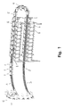
- a carrier means to which the conveyor units 1 are connected moves in an endless main track 2 that have sections 3 that curves in the horizontal plane and section 4 that curves in the vertical plane forming vertical half-turns. For clarity, only a limited number of conveyor units are shown in fig. 1.
- An endless belt extending to one side from the vertical plane of the carrier means constitutes the article-supporting surface 5 of each conveyor unit 1.
- the endless belt or cross-belt may be moved in a direction perpendicular to the transport direction and articles may be discharged to either side of the conveyor unit 1.
- the article-supporting surface 5 may also be constituted by other devices, such as, e.g., a tray that may be tiltable in both directions.
- the control system of the conveyor system is adapted to control the loading of articles onto and discharging of articles from the conveyor system.
- the conveyor units 1 are label uniquely with an automatically readable identification mark, such as, e.g., a bar code label in order to identify the individual conveyor units 1.
- the conveyor system further comprises reading means for reading the identification marks at least at one position along the track of the conveyor system, preferably at the loading stations and at the discharge stations 6.
- a main control unit has means for communicating with the control units of each individual conveyor unit 1 which controls a drive unit on each conveyor unit 1 for driving the endless belt in a given direction to discharge articles from the article-supporting surface 5 at a predetermined discharge station 6.
- the conveyor system further comprises means for driving the conveyor units 1, such as, e.g., a linear motor that is driving at least some of the conveyor units, one or more electro-motors driving the carrier means, etc, and it also comprises one or more loading stations for loading articles onto the article-supporting surfaces 5.
- means for driving the conveyor units such as, e.g., a linear motor that is driving at least some of the conveyor units, one or more electro-motors driving the carrier means, etc, and it also comprises one or more loading stations for loading articles onto the article-supporting surfaces 5.
- a low radius of curvature of the curved main track sections 3, 4 make the conveyor system very flexible and allows for a very high spatial exploitation.
- the main track sections 4 that form half-turns in the vertical plane allow for discharge stations 6 to be stacked in the vertical direction.
- special arrangements must be made at the vertical half-turns 4 of the main track 2 to prevent the article-supporting surfaces 5 of the conveyor units 1 from tilting so as to prevent the articles transported by the conveyor units 1 from being unintentionally discharged.
- the monorail sections forming the main track 2 on straight track sections and track sections curving in the horizontal plane are preferably made from a profile of extruded aluminium.
- a cross-section of a profile is shown in fig. 2 and cross-sections of monorails mounted with a conveyor unit 1 and equipped for operation are shown in figs. 3-5.
- the profile forms a nearly closed room in which the drive chain can move.
- An opening 7 to one side enables the connection between the drive chain and the conveyor units 1.
- the opening 7 is small compared to the total circumference of the profile, forming only about a tenth of the circumference so that the profile has a high stiffness about the longitudinal axis.
- the opening 7 is placed at one side of the profile to prevent dust and other impurities from settling into the interior of the profile and to enable vertical half-turns 4 of the main track 2.
- a number of cavities 8 are formed within the profile to increase the longitudinal stiffness with low added material consumption.
- the profile furthermore has grooves 9 for assembling adjacent sections of the main track 2 and grooves 10 for mounting of cabling for power supply to the drive unit and for control of the conveyor and optionally for power supply to the conveyor units 1.
- a shield for covering the cabling, control and power-supply units, etc. may be mounted on protrusions 11 placed on both sides of the profile.
- the profile has a groove 23 next to the conveyor units 1 in which a stationary part of a cordless energy transfer system may be mounted.
- the conveyor units 1 may have a demand for a power supply for driving, e.g., a cross-belt, a discharge device for a tilt tray and/or a control unit for controlling the operation of the conveyor unit 1.
- Energy may be transferred to the conveyor unit 1 by means of a conductor rail on the main track 2 and a collector shoe on each conveyor unit 1 or by means of an inductive energy transfer system with a primary side on the main track 2 and a secondary side on each conveyor unit 1.
- the conveyor unit may receive energy from the drive system by having a generator connected to a support wheel of the conveyor unit 1.
- Two rooms 24, 25 separated by a wall 26 give room for the power supply for the linear motor drive 27 and for cabling for the control units and means, respectively.
- the two types of cabling are separated to be in accordance with various safety-regulations.
- An opening 27 between the two rooms 24, 25 and the covering shield 28 gives room for mounting of additional power supply units, control units, power supply for the energy supply system for the conveyor units 1, etc.
- the drive chain is driven by means of a linear motor drive comprising a number of stator parts 29 placed along the main track 2 and reaction plates 30 mounted on the drive chain.
- the use of a monorail on which the conveyor units 1 run is, especially when the monorail is made from one extruded profile, advantageous as compared to known systems having tracks on both sides of the article-supporting surface.
- the monorail is more flexible in installation and requires a simpler support arrangement than two parallel tracks and parts of the main track 2 may even be placed on a vertical wall.
- a monorail having room for the drive chain in the interior and with an opening in the side of the profile permits for vertical half-turns 4 in the path of the main track 2.
- the three configurations in figs. 3-5 shows different conveyor systems using a monorail.
- the ones shown in figs. 3 and 4 has the conveyor unit 1 and the article-supporting surface 5 arranged on one side of the main track 2, thus permitting for vertical half-turns 4 of the path of the main track 2.
- the configuration shown in fig. 3 is suitable for conveying articles of a maximum weight of 5-8 kg, whereas the configuration shown in fig. 4 is suitable for a maximum weight of 12 kg or more, depending on the size and shape of the protruding arm 31 with which the support wheel 15 engages.
- the arm 31 makes it possible to make the conveyor more stable in the transversal direction but is also more expensive to either have extruded on the profile or extruded separately and subsequently mounted on the profile.
- the configuration shown in fig. 5 is a horizontal configuration which is very stable but does not permit for vertical half-turns 4.
- the drive chain on which the conveyor units are mounted is shown in two configurations in figs. 6-7 and figs. 8-9 for use in a purely horizontal configuration and in a configuration for vertical half-turns 4, respectively.
- the drive chain comprises a plurality of longer links 32 carrying the reaction plates 30 for the linear motor drive coupled together by two shorter links 33 between each two longer links 32.
- the short links are pivotally connected to one end of a longer link about pivot pins 34 being substantially vertical and carrying the directing wheels 18, 22 of a diameter of 70 mm for guiding the chain and delimiting slack in the transversal direction.
- Each pair of two shorter links 33 are pivotally interconnected with a common, substantially horizontal pivot pin 35 carrying the support wheels 14, 15, 36 of a diameter of 47 mm for supporting the conveyor unit 1.
- the drive chain is flexible in the vertical plane as well as in the horizontal plane and the support wheels 14, 15 will run correctly without broadsiding through all curves of the main track 2 by forming the drive chain in this manner.
- the weight of the conveyor unit 1 and the article supported thereon is during normal operation supported by the reaction force between the surface 13 on the monorail and the associated support wheel 15.
- the torque caused by the vertical distance between the centre of gravity of the conveyor unit 1 and the point of vertical support defined by the wheel 15 and the surface 1 3 is counteracted by the reaction force between the surface 12 and the associated support wheel 14.
- the reaction force between the surface 13 and the wheel 15 counterbalances the gravity force on the conveyor unit 1 (and of the drive chain) as well as the reaction force caused by the torque.
- the pivot pin 35 carries the conveyor unit 1 and constitutes the main axis of the conveyor unit about which it pivots during passage of vertical half-turns 4.
- the support wheel 36 is only engaging a surface 19 of the main track 2 during passage of vertical half-turns 4 where there is not enough room for the surface 13 with which the support wheel 15 engages on straight main track sections.
- the support wheel 36 is situated at a longer vertical distance from the centre of gravity of the conveyor unit 1 and closer to the other support wheel 14 and the support of the conveyor unit 1 is therefore less stable when support wheel 36 takes over the function of support wheel 15 but this effect is counterweighted by the stabilising influence of the guide means that engages with a guide track at the vertical half-turns 4 as will be described below.
- the directing wheels 18, 22 are broad, 70 mm of diameter, so as to allow for as well broad as long reaction plates 30 with a small distance to the directing wheel 22.
- the reaction plates 30 move as chords to the curve of the main track 2 during passage of vertical half-turns 4 and the dimensions can be made more suitable if the ends of the reaction plates 30 are able to enter the opening in which the directing wheels 18, 22 runs.
- the smaller diameter of 47 mm of the support wheels 14, 15, 36 is chosen as a compromise between limiting the dimensions of the extruded profile, which calls for smaller diameter, and minimising the friction losses between wheels and track, which calls for larger diameter.
- At least the outer rim of the support wheels 14, 15, 36 and the directing wheels 18, 22 are suitably made from a plastics material of a suitable hardness, such as a hardness in the Shore A range, e.g. Shore 80-100 such as Shore 85-95.
- a suitable hardness such as a hardness in the Shore A range, e.g. Shore 80-100 such as Shore 85-95.
- An example of such material is polyurethane Shore 90-92 plus/minus 3. It is preferred that the surface of the wheels 14, 15, 36, 18, 22, primary the directing wheels 18, 22, has a low friction coefficient, for which reason the plastics material may comprise about 15% by weight of polytetraflouroethylene.
- the drive chain configuration for vertical half-turns as shown in figs. 8-9 has a directing wheel 18, 22 on each side of the vertical pivot pin 34 so that the chain may turn 180 degrees about a transversal axis in a vertical half-turn 4 and still operate in a main track as shown in figs. 3-5.
- the longer links 32 has a second reaction plate 30 (not shown) mounted on the opposite side of the reaction plate 30 shown on figs. 8-9 for the same reason.
- the drive chain for purely horizontal operation it not equipped with these extra directing wheels 22 and reaction plates 30 and does not have the extra support wheel 36.
- the drive chains are designed for being flexible in the horizontal plane as well as in the vertical plane and having as long reaction plates 30 as possible to increase the efficiency of the linear drive by delimiting the number of air gaps between consecutive reaction plates 30.
- the length of the reaction plates 30 is limited by the radius of curvature of the main track because the reaction plates 30 are stiff and move as chords to the curving path of the main track 2 and because the pivot axis of the directing wheels 18, 22 will be non-perpendicular to the curve of the main track during passage of a vertical half-turn 4 for which reason the directing wheels will broadside in their tracks.
- the broadsiding causes wear on directing wheels 18, 22 and tracks in the vertical half-turns 4 for which reason the surface of the wheels 18, 22 preferably are made from a low-friction material.
- the deviation from a right angle between the pivot axis of the directing wheels 18, 22 and the curve of the main track depends on the distance between two vertical pivot pins 34 of a longer link 32 and the radius of curvature of the main track section.
- the deviation should be less than 15 degrees and is in a preferred embodiment between 7 and 11 degrees, such as 9 degrees.
- the conveyor units 1 are connected to carrier means, the drive chain, with a horizontal pivot pin 35 about which the conveyor unit 1 may pivot.
- Each conveyor unit 1 is equipped with a first guide wheel 37 that engages with a first track parallel to the main track when the conveyor unit 1 is moving on straight main track sections in order to prevent the conveyor unit 1 and thereby the article-supporting surface 5 from tilting.
- the first guide wheel 37 disengages with the first guide track when the conveyor unit 1 enters a vertical half-turn 4 and guide means for preventing the conveyor unit 1 from tilting during the passage of the vertical half-turn 4 of the main track 2 comes into action.
- FIG. 10-12 An embodiment having a first guide wheel 37 can be seen in figs. 10-12 and the first guide wheel 37 is also shown in the cross-sections in figs. 3-5. A number of different embodiments of the guide means at vertical half-turns are shown in figs. 10-29.
- the first guide wheel is arranged in the same horizontal plane as the support wheels 14, 15, 36 but with a horizontal distance in the transport direction of the conveyor to the pivot pin 35.
- the first guide track is preferably displaced in the transverse direction of the conveyor relatively to the surface 13 on which the support wheels 15 engage so as to enable individual engagement of the two wheels 15, 37.
- One arrangement according to the invention for preserving a horizontal position of the article-supporting surface 5 of the conveyor units 1 at a vertically curving section 4 of the main track 2 is shown on figs. 10-12.
- the first guide wheel 37 of the conveyor section disengages with the first guide track when the conveyor unit 1 enters a vertical half-turn 4 of the main track 2 and a second guide wheel 38 engages with a second guide track 39.
- the second guide wheel 38 and the second guide track 39 prevents, due to the design of the second guide track 39, the conveyor unit 1 from tilting when it moves on vertical half-turns 4 of the main track 2.
- the second guide wheel 38 disengages again with the second guide track 39 when the conveyor unit 1 leaves the vertical half-turns 4 of the main track section 2 and the first guide wheel 37 engages the fist guide track.
- Both guiding wheels 37, 39 are simultaneously engaging with their respective guide tracks over a short distance when the conveyor unit 1 moves into or out from the vertical half-turns 4 of the main track section 2 so as to ensure stability of the conveyor unit 1.
- a conveyor unit 1 according to the embodiment of the invention as shown in fig. 10 is shown in figs. 11 and 12.
- the second guide wheel 38 and the second guide track 39 are arranged in a vertical plane parallel to the vertical plane of the carrier means 40 but displaced in the transverse direction so that the conveyor unit 1 passes between the two vertical planes when it moves on the vertical half-turns 4 of the main track 2.
- the path in the vertical plane of the second guide track 39 may cross the path of the curving main track section 4.
- the second guide wheel 18 is preferably mounted on the conveyor unit 1 with a resilient bar 41 as shown in fig. 12 in order to obtain an improved stability of the conveyor system.
- the article-supporting surface 5 is in the embodiment shown on fig. 11 arranged in a horizontal plane below the main track 2 so that the articles that are discharged to that side pass under the main track 2.
- An alternative embodiment where the article-supporting surface 5 is arranged in a horizontal plane above the main track 2 is shown on e.g. fig. 16 which impose less restrictions on the height of the transported articles.
- FIG. 13 Another embodiment of the invention is shown in figs. 13 and 14.
- this embodiment has an arrangement with two wheels 42 arranged on a bar 43 that pivotally connected to the conveyor unit 1.
- the two wheels 42 are engaging each side of a second guide track 39 and the wheels 42 are preferably resiliently biased towards the second guide track 39.
- FIG. 15-16 Further modifications of the embodiment as shown in figs. 10-12 are shown in figs. 15-16 and figs. 17-18.
- the embodiment shown in figs. 15-16 comprises a third guide wheel 44 and a third guide track 45.
- the second and third guide wheels 38, 44 are positioned on the conveyor unit 1 so that they are not on line with the pivot pin 35, the axis of the wheels 38, 44 and the pin 35 are rather forming an obtuse-angled triangle in a vertical plane, so as to prevent the conveyor unit 1 from having any positions along a vertical half-turn 4 of the main track 2 at which the unit 1 may rotate or tilt in a vertical plane.
- the embodiment shown in figs. 17-18 further comprises a fourth guide wheel 46 and a fourth guide track 47, the fourth guide wheel 46 having substantially the same axis of rotation as the pivot pin 35 and the fourth guide track 47 follows the path of the main track 2 but in a vertical near the plane of the second and third guide tracks 39, 45.
- the fourth guide wheel 46 substantially prevents the conveyor unit 1 from rotating or tilting in the plane of the tracks 2, 39, 45 during passage of a vertical half-turn 4 of the main track 2, due so slack or clearance in the various wheels and tracks and/or in the carrier means 40.
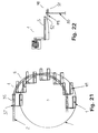
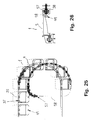
- FIG. 19-20 Yet another four embodiments of the invention are shown in figs. 19-20, figs. 21-22, figs. 23-24 and in figs. 25-26. These embodiments all comprise a synchronising means arranged in a vertical plane parallel to the vertical plane of the carrier means 40.
- the synchronising means comprises a plurality of coupling means 48, such as, e.g. rods, adapted for engaging with a guide member 49, such as, e.g. a member with a indentation, of each conveyor unit 1 when the conveyor unit 1 enters a vertical half-turn 4 of the main track 2.
- the distance between immediately adjacent coupling means 48 is substantially equal to the distance between the guide members 49 of immediately adjacent conveyor units 1 and the path along which the synchronisation means moves the coupling means 48 relative to the main track 2 adapts the arrangement for preventing the conveyor units 1 from tilting when they pass a vertical half-turn 4 of the main track 2.
- the synchronisation means are in all embodiments driven by the engagement with the conveyor units 1.
- the embodiments further comprises a guide wheel 37 on each conveyor unit 1 which disengages with a guide track when the conveyor unit 1 enters a vertical half-turn 4 of the main track 2.
- the synchronisation means comprises a disc member 50 arranged pivotally about a horizontal axis and the coupling means 48 are arranged on the disc member 50.
- the coupling means 48 comprises electromagnets 51 that are activated to couple with a magnetic component of the guide members 49 of each conveyor unit 1.
- the magnetic component of the guide member 49 is arranged so that is may rotate about an axis 52 being parallel to the axis of the pivot pin 35.
- the embodiment shown on figs. 23-24 has a synchronisation means comprising a non-moving part 53 with an outer surface 54 that defines a path or track for the synchronisation wheels 55.
- the synchronisation wheels 55 each guides a coupling means 48 that is resiliently biased towards the surface 54 by a disc member 56 that also keeps the predetermined distance between the coupling means 48.
- the synchronisation means of this embodiment is more flexible than the previous three and comprises a synchronisation chain 57 on which the coupling means 48 are arranged.
- the synchronisation chain 57 moves in a synchronisation track 58 that may follow any path that the main track 2 may follow and does therefore not require that the vertical half-turn 4 of the main track 2 follows a semi-circular path.
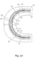
- a preferred embodiment of an arrangement for preventing the conveyor units 1 from turning or tilting when passing a vertical half-turn 4 of the main track 2 is shown in figs. 27-30.
- the embodiment resembles the one shown in figs. 17-18 with the exception that it is not mandatory in the preferred embodiment that the fourth guide wheel 46 has substantially the same axis of rotation as the pivot pin 35.
- the second 38, third 44 and fourth guide wheels 46 are arranged in an obtuse-angled triangle in each their adjacent vertical planes as shown in fig. 18 so that the respective guide tracks 39, 45, 47 may cross each other.
- the path of the guide tracks 39, 45, 47 is shown in fig. 27.
- the guide tracks 39, 45, 47 are formed by rolling an aluminium bar 59 into the correct shape, fasten it to a support plate 60 and form the tracks 39, 45, 47 by milling the bar 59.
- the bar with the tracks 39, 45, 47 is shown mounted together with the main track 2 at a vertical half-turn 4 of the main track 2 in figs. 28 and 29 as viewed from two sides.
- the main track 2 at a vertical half-turn 4 of the main track 2 is formed from rolled profiles 61 shaped so that the drive chain is suitably supported when passing the half-turn 4.
- the directing wheel 18, 22 of the drive chain being closest to the point of curvature is the one engaging the track. It has shown to be advantageous to obtain a low-friction contact between the directing wheel 18, 22 and the track at the vertical half-turn 4 because the wheel 18, 22 will broadside during the passage of the half-turn as described previously.
- a suitable way of decreasing the friction factor of the surface of the track is to provide it with a layer of polyamide such as polyamide 6 preferably by spraying it on the tracks.
- the milled profiles 61 forming the main track 2 are mounted on a support plate 62 as shown in figs. 28-29.
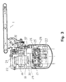
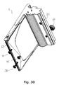
- Three conveyor units 1 are shown in figs. 30-32, each being equipped with a cross-belt 63 forming the article-supporting surface 5 of the conveyor units 5, a first guide wheel 37 and an opening 64 for engaging pivotally with the pivot pin 35.
- the conveyor unit 1 shown in fig. 30 is suitable for use in a system with vertical half-turns 4 of the main track 2 whereas the one shown in fig. 31 is suited for a purely horizontal configuration.
- the part of the conveyor unit 1 carrying the cross-belt 63 is preferably hinged to a frame part of the conveyor unit 1 as shown in fig. 32 so as to provide easy access to the interior of the frame part wherein the drive motor 65 for driving the cross-belt 63 is placed together with a control unit and an electric storage battery so that the power supply to the conveyor unit may be temporarily during its passage of the main track 2.
Abstract
Description
Claims (21)
- A conveyor for transporting articles and comprisingcharacterised in thata plurality of conveyor units (1),an endless carrier means, such as a chain, to which each conveyor unit (1) is connected,an endless main track (2) in which the carrier means is moving in a transport direction, said track comprising at least a first substantially straight main track section, a second substantially straight main track section, and a curving main track section (4) being connected at a first end to the first main track section and at a second end to the second main track section, the first and second main track section being arranged in two levels in the same vertical plane so that their respective transport directions are of opposite direction,each conveyor unit (1) being connected pivotally to the carrier means so as to allow the conveyor unit (1) to pivot relatively to the carrier means about a main axis of the conveyor unit (1), each conveyor unit (1) comprising an article-supporting member that extends away from the vertical plane of the carrier means and a first guide member of the conveyor unit (1), andfirst guiding means arranged in a vertical plane being parallel to the vertical plane of the carrier means and adapted to co-operate with the first guide member of each of said plurality of conveyor units (1) when the conveyor unit (1) moves along at least a part of the at least one curving section (4) of said main track (2), so as to counteract or prevent the article supporting member from tilting from its position relative to the horizontal plane,
the article supporting members of the conveyor units (1) being arranged between the vertical plane of the first guiding means and the vertical plane of the carrier means when the conveyor units (1) are moving along said curving main track section (4). - A conveyor according to claim 1 comprising a second guiding means that extends substantially parallel to at least a substantial part of the main track (2), each conveyor unit (1) comprises a second guide member adapted to co-operate with said second guiding means when the conveyor unit (1) moves along at least a substantial part of straight sections of said main track (2), the second guiding means and the second guide members when co-operating are adapted to counteract or prevent the article-supporting member from tilting from its position relative to the horizontal plane.
- A conveyor according to claim 2, wherein the first and second guide members of each conveyor unit (1) and the first and second guiding means are adapted so that the first guide member co-operates with the first guiding means when the conveyor unit (1) enters the curving main track section (4) and before the second guide member disengages with the second guiding means and so that the second guide member co-operates with the second guiding means when the conveyor unit (1) leaves the curving main track section (4) and before the first guide member disengages with the first guiding means.
- A conveyor according to any of the preceding claims comprising torque-absorbing means arranged in substantially the same vertical plane as the carrier means, said torque-absorbing means being adapted to absorb a torque applied by the conveyor units (1) about an axis being substantially parallel to the transport direction
- A conveyor according to claim 4, wherein the torque-absorbing means constitutes an integrated part of the carrier means.
- A conveyor according to any of the preceding claims, wherein the first and the second main track sections are substantially horizontal.
- A conveyor according to any of the preceding claims, wherein the main axis of each conveyor unit (1) is substantially horizontal and substantially perpendicular to the transport direction.
- A conveyor according to any of the preceding claims, wherein each article-supporting member has a substantially horizontal article-supporting upper surface (5).
- A conveyor according to any of claims 2-8, wherein the second guide member and the second guiding means are arranged in substantially the same vertical plane as the carrier means or in a vertical plane closely adjacent to said plane.
- A conveyor according to any of the preceding claims, wherein the first guide member of at least one conveyor unit (1) comprises two wheels (38, 44) arranged in substantially the same vertical plane with a spacing in between and arranged pivotally on a bar being pivotally arranged on the conveyor unit (1) about an common axis that extends substantially midway between and substantially parallel to the axes of said two wheels (38, 44), said common axis being substantially parallel to the main axis of the conveyor unit (1), the first guiding means comprising a track (39, 45) protruding from a vertical plane and comprising two parallel surfaces with which said two wheels (38, 44) co-operate with said track (39, 45) in between said two wheels (38, 44) when the first guide member co-operates with the first guiding means.
- A conveyor according to claim 10, wherein at least one of said two wheels of the first guide member is resiliently biased against said track of the first guiding means when the first guide member co-operates with the first guiding means.
- A conveyor according to any of claims 2-11 and further comprising a third guiding means arranged in substantially in the same vertical plane as the first guiding means, each conveyor unit (1) comprises a third guide member adapted to co-operate with said third guiding means, the second and third guiding means being adapted so that the third guide member co-operates with the third guiding means when the conveyor unit (1) enters the curving main track section (4) and before the second guide member disengages with the second guiding means and so that the second guide member co-operates with the second guiding means when the conveyor unit (1) leaves the curving main track section (4) and before the third guide member disengages with the third guiding means.
- A conveyor according to claim 12 and further comprising a fourth guiding means arranged in substantially in the same vertical plane as the first guiding means, each conveyor unit (1) comprises a fourth guide member adapted to co-operate with said fourth guiding means, the first, third and fourth guiding members of each conveyor unit (1) forming an obtuse-angled triangle in a vertical plane.
- A conveyor according to claim 12, the first, second and third guide members of each conveyor unit (1) and the first, second and third guiding means being adapted so that the first guide member co-operates with the first guiding means when the conveyor unit (1) enters the curving main track section (4) and before the second guide member disengages with the second guiding means, so that the third guide member co-operates with the third guiding means before the first guide member disengages with the first guiding means when the conveyor unit (1) passes a given position along the curving main track section (4), and so that the second guide member co-operates with the second guiding means when the conveyor unit (1) leaves the curving main track section (4) and before the third guide member disengages with the third guiding means.
- A conveyor according to any of claims 1-9, wherein the first guiding means comprises a plurality of coupling devices arranged on a common synchronising device, each coupling device being adapted to co-operate with one first guide member of a conveyor unit (1) when the conveyor unit (1) enters the curving main track section (4) and to disengage with the first guide member when the conveyor unit (1) leaves the curving main track section (4), the coupling devices being arranged on the synchronising device with a distance between immediately adjacent coupling devices substantially equal to the distance between the first guide members of immediately adjacent conveyor units (1).
- A conveyor according to claim 15, wherein the curving main track section (4) is shaped substantially as an arc of a circle when projected on the vertical plane of the carrier means, and where the synchronising device comprises a disc member (50) which is pivotally arranged about an axis being substantially parallel to the main axes of the conveyor units (1), on which disc member (50) the coupling devices are arranged substantially in a circle with centre at the pivot axis of the disc member.
- A conveyor according to claim 16, wherein the first guide member of each conveyor unit (1) comprises a guide component made form a magnetic susceptible material, the guide component being arranged to pivot about an axis being substantially parallel to the main axis of the conveyor unit (1), and the coupling devices each comprises an electromagnet, the synchronising device further comprises means for providing power supply to the coupling devices and means for controlling the activation and deactivation of the electromagnet of each coupling device.
- A conveyor according to claim 15, wherein the synchronising device comprises an endless synchronising chain (57) on which the coupling devices are arranged, and wherein the first guiding member further comprises a synchronising track (58) in which the synchronising chain (57) is moving.
- A conveyor according to claim 15, wherein the synchronising device comprises an endless synchronising track (58) on which a plurality of synchronising wheels each comprising a coupling device is moving and wherein the synchronising wheels are kept with a substantially equal distance between immediately adjacent synchronising wheels and are resiliently biased towards said track (58) by a disc member which is allowed to rotate about an axis that is substantially parallel to the first axes of the conveyor units (1) when these are moving on the curving main track.
- A conveyor according to any of the preceding claims, wherein the article supporting member comprises an endless belt being movable in a direction perpendicular to the transport direction.
- A conveyor according to any of claim 1-19, wherein the article supporting member comprises a tray being tiltable in a direction perpendicular to the transport direction.
Applications Claiming Priority (5)
| Application Number | Priority Date | Filing Date | Title |
|---|---|---|---|
| DK155697 | 1997-12-30 | ||
| DK155697 | 1997-12-30 | ||
| DKPA199801343 | 1998-10-20 | ||
| DK134398 | 1998-10-20 | ||
| PCT/DK1998/000586 WO1999035064A1 (en) | 1997-12-30 | 1998-12-30 | A conveyor |
Publications (2)
| Publication Number | Publication Date |
|---|---|
| EP1044148A1 EP1044148A1 (en) | 2000-10-18 |
| EP1044148B1 true EP1044148B1 (en) | 2004-05-12 |
Family
ID=26065615
Family Applications (1)
| Application Number | Title | Priority Date | Filing Date |
|---|---|---|---|
| EP98963396A Expired - Lifetime EP1044148B1 (en) | 1997-12-30 | 1998-12-30 | A conveyor |
Country Status (7)
| Country | Link |
|---|---|
| US (1) | US6533106B1 (en) |
| EP (1) | EP1044148B1 (en) |
| JP (1) | JP2002500145A (en) |
| AT (1) | ATE266588T1 (en) |
| AU (1) | AU1869599A (en) |
| DE (1) | DE69823874T2 (en) |
| WO (1) | WO1999035064A1 (en) |
Families Citing this family (12)
| Publication number | Priority date | Publication date | Assignee | Title |
|---|---|---|---|---|
| WO2000032502A1 (en) | 1998-12-01 | 2000-06-08 | Crisplant A/S | A conveyor/sorter system, a loading conveyor and a control system for such conveyors |
| ITPD20020086A1 (en) * | 2002-04-05 | 2003-10-06 | Eurotecnica Engineering Srl | BOOK TRANSFER DEVICE WITH BACK COOLING |
| AU2003226892A1 (en) * | 2003-03-17 | 2004-10-11 | Crisplant A/S | A space adjustable conveyor with article carriers |
| US7287749B2 (en) * | 2003-11-05 | 2007-10-30 | Heidelberger Druckmaschinen Ag | Transport system in a machine that processes printing material |
| DE102004031443A1 (en) * | 2004-06-29 | 2006-01-26 | Bosch Rexroth Aktiengesellschaft | Conveying device with a trolley with achsfluchtenden casters |
| EP1876116A1 (en) * | 2006-06-26 | 2008-01-09 | Carl Freudenberg KG | Roller for guiding and transporting purposes |
| DE102010053426B3 (en) * | 2010-11-30 | 2012-06-06 | SSI Schäfer PEEM GmbH | Drive chain for suspension conveyor for transporting hanging articles, particularly garments between remote locations, comprises multiple tension rod elements, which are connected by coupling elements |
| KR20130049080A (en) * | 2011-11-03 | 2013-05-13 | 삼성디스플레이 주식회사 | Rotating type thin film depositing apparatus and the thin film depositing method using the same |
| WO2016154517A1 (en) | 2015-03-25 | 2016-09-29 | Joseph Porat | Stacked tilt tray and cross-belt sorting system |
| EP3533733B1 (en) * | 2018-02-28 | 2022-12-14 | Franke Technology and Trademark Ltd | Conveyor system for the transport of packaged food products |
| CN109018898A (en) * | 2018-08-28 | 2018-12-18 | 河南省德耀节能科技股份有限公司北京分公司 | Calcium carbide pipeline and its delivery track |
| CN115355704B (en) * | 2022-08-23 | 2023-12-01 | 上海麦牙科技有限公司 | Conveying mechanism, conveying method, dryer and drying method |
Citations (2)
| Publication number | Priority date | Publication date | Assignee | Title |
|---|---|---|---|---|
| JPH0412930A (en) * | 1990-04-27 | 1992-01-17 | Shin Suzuki | Vertical sorter |
| JPH0728121A (en) * | 1994-01-26 | 1995-01-31 | Nikon Corp | Camera system |
Family Cites Families (39)
| Publication number | Priority date | Publication date | Assignee | Title |
|---|---|---|---|---|
| US1270001A (en) * | 1915-12-15 | 1918-06-18 | Orlando J Boos | Conveyer mechanism. |
| US1240172A (en) * | 1916-06-03 | 1917-09-18 | Minnesota Manufacturers Ass | Elevator. |
| US1643224A (en) * | 1925-03-12 | 1927-09-20 | Shelton Frederick James | Means for displaying goods, merchandise, or the like |
| US1931141A (en) * | 1930-09-17 | 1933-10-17 | Standard Conveyor Co | Endless chain elevator and conveyer |
| US2078770A (en) * | 1933-08-12 | 1937-04-27 | Mechanical Parking Patents Inc | Parking tower |
| US2339494A (en) * | 1941-12-01 | 1944-01-18 | Baker Perkins Inc | Traveling tray conveyer |
| US2912118A (en) * | 1950-06-17 | 1959-11-10 | Diebold Inc | Elevator filing appliance |
| US3062358A (en) * | 1960-06-06 | 1962-11-06 | Theodore M Woodward | Conveyor for parking cars and the like |
| DE1240503B (en) | 1963-06-07 | 1967-05-18 | Erwin O Haberfeld | Index card device with card index holders that run around like a paternoster |
| DE1235857B (en) * | 1963-08-23 | 1967-03-09 | Zippel Kg Herbert | Slide track for a registry with circumferential carriers for documents |
| US3655031A (en) * | 1970-07-16 | 1972-04-11 | Robert L Cahn | Conveyor apparatus for individual supports |
| DE2100056A1 (en) | 1971-01-02 | 1972-07-27 | Daimler Benz Ag | Link belt conveyor |
| DE2148778A1 (en) | 1971-09-30 | 1973-04-05 | Stierlen Werke Ag | CONVEYOR DEVICE FOR CONVEYED TRANSPORT GOODS, IN PARTICULAR FOOD TRAYS, IN THE SAME POSITION |
| DE2537944A1 (en) * | 1974-09-09 | 1976-03-18 | Frantl Conprojekt | ENDLESS CHAIN CONVEYOR, IN PARTICULAR FOR MOTOR VEHICLES |
| AT347333B (en) | 1974-09-09 | 1978-12-27 | Frantl Conprojekt | ENDLESS CHAIN CONVEYOR, IN PARTICULAR FOR MOTOR VEHICLES |
| FR2374235A1 (en) | 1976-12-17 | 1978-07-13 | Nal Pour Expl Oceans Centre | DEVICE FOR UNLOADING DREDGING BUCKETS |
| US4171042A (en) * | 1977-11-07 | 1979-10-16 | California Processing Machinery | Fruit positioning apparatus |
| US4199291A (en) * | 1978-04-12 | 1980-04-22 | A-T-O Inc. | Velocity compensator assembly in a horizontal article conveyor system |
| GB2025343A (en) * | 1978-05-23 | 1980-01-23 | Cosan Crisplant As | Sorting tray-type conveyor |
| SE424434B (en) | 1979-08-02 | 1982-07-19 | Ifo Kampri Ab | TRANSPORTER, INCLUDING GREAT ELEMENTS CONTROLLED BY A STATION ROAD |
| SU865721A1 (en) | 1980-01-02 | 1981-09-23 | Центральное Проектно-Конструкторское И Технологическое Бюро Министерства Легкой Промышленности Латсср | Sheelf-type elevator |
| DE3032032A1 (en) | 1980-08-25 | 1982-04-01 | Eckhard Franz Josef Ing.(grad.) 6400 Fulda Buhl | Reversing point bearing for chain wheels - has each chain wheel coordinated with curved guide track and guide elements |
| DE3273561D1 (en) * | 1981-07-17 | 1986-11-06 | Nevo Hacohen Jacob I | Conveyor elevator apparatus |
| CH662099A5 (en) | 1984-02-09 | 1987-09-15 | Daverio Ag | DISTRIBUTOR FOR PIECE. |
| US4733768A (en) | 1985-09-04 | 1988-03-29 | Agostino Aquino | Selective ejection conveyors |
| US4987992A (en) * | 1989-01-09 | 1991-01-29 | Pflow Industries Inc. | Material transfer apparatus |
| DE4002665A1 (en) | 1990-01-30 | 1991-08-01 | Herbert M Jochum | Vertical car storage bark |
| JPH0798569B2 (en) | 1990-02-14 | 1995-10-25 | 株式会社椿本チエイン | 3D automatic sorting device |
| US5101963A (en) * | 1991-06-17 | 1992-04-07 | Motion Systems, Inc. | Vertical lift unit |
| JPH0562727A (en) | 1991-08-30 | 1993-03-12 | Fujitsu Ltd | Anisotropic conductive connection member and its manufacture |
| JPH0544906U (en) | 1991-10-18 | 1993-06-15 | 株式会社椿本チエイン | Horizontal holding device for loading platform that circulates in the vertical direction |
| BE1005757A5 (en) | 1992-04-01 | 1994-01-18 | Etn P Ghistelinck N V | Mobile stacking equipment |
| DE4236340C2 (en) | 1992-10-28 | 1994-11-10 | Daimler Benz Ag | Arrangement for the inductive transmission of energy |
| US5492066A (en) | 1993-07-30 | 1996-02-20 | Shinko Electric Co., Ltd. | Transport system |
| EP0662433B1 (en) | 1994-01-07 | 1997-05-02 | Electronic Systems S.P.A. | Handling-switching apparatus |
| DE59506624D1 (en) | 1994-05-19 | 1999-09-23 | Cornel Hoegger | Arrangement for storing and conveying objects, especially storage containers |
| DE4446779C2 (en) | 1994-12-24 | 1996-12-19 | Daimler Benz Ag | Arrangement for the contactless inductive transmission of electrical power |
| CN1081959C (en) | 1995-10-30 | 2002-04-03 | 西门子公司 | Sorting arrangement, in particular for items of post |
| US6119880A (en) * | 1997-03-25 | 2000-09-19 | Dueck; Raymond | Shelf carousel |
-
1998
- 1998-12-30 JP JP2000527478A patent/JP2002500145A/en active Pending
- 1998-12-30 EP EP98963396A patent/EP1044148B1/en not_active Expired - Lifetime
- 1998-12-30 WO PCT/DK1998/000586 patent/WO1999035064A1/en active IP Right Grant
- 1998-12-30 AT AT98963396T patent/ATE266588T1/en not_active IP Right Cessation
- 1998-12-30 US US09/222,959 patent/US6533106B1/en not_active Expired - Lifetime
- 1998-12-30 AU AU18695/99A patent/AU1869599A/en not_active Abandoned
- 1998-12-30 DE DE69823874T patent/DE69823874T2/en not_active Expired - Lifetime
Patent Citations (2)
| Publication number | Priority date | Publication date | Assignee | Title |
|---|---|---|---|---|
| JPH0412930A (en) * | 1990-04-27 | 1992-01-17 | Shin Suzuki | Vertical sorter |
| JPH0728121A (en) * | 1994-01-26 | 1995-01-31 | Nikon Corp | Camera system |
Also Published As
| Publication number | Publication date |
|---|---|
| DE69823874T2 (en) | 2005-05-25 |
| ATE266588T1 (en) | 2004-05-15 |
| JP2002500145A (en) | 2002-01-08 |
| WO1999035064A1 (en) | 1999-07-15 |
| US6533106B1 (en) | 2003-03-18 |
| AU1869599A (en) | 1999-07-26 |
| EP1044148A1 (en) | 2000-10-18 |
| DE69823874D1 (en) | 2004-06-17 |
Similar Documents
| Publication | Publication Date | Title |
|---|---|---|
| EP1044148B1 (en) | A conveyor | |
| US8474594B2 (en) | Drive unit, drive system and conveyor installation for skid supporting an object | |
| US6360673B1 (en) | Trolley chassis | |
| US11279382B2 (en) | Transport carriage and system for transporting objects | |
| US6607066B1 (en) | Conveyor | |
| US20060157320A1 (en) | Curved assembly line and/or conveyor belt | |
| US5014625A (en) | Linear motor driven trolley conveyor | |
| US6371032B1 (en) | Trolley with passive discharge mechanism | |
| JP3453076B2 (en) | Carrier type transport device | |
| EP1196341B1 (en) | A sorting conveyer with a tilting mechanism | |
| US6415721B1 (en) | Storage conveyor for hybrid carrying truck | |
| US5960938A (en) | Conveyor for cantilevered loads | |
| US6712194B1 (en) | Sorting conveyer with a tilting mechanism | |
| US20110005902A1 (en) | Roller conveyor and a roller path system therefor | |
| RU2681469C2 (en) | Geared trolley for transportation and sorting of items | |
| US6378440B1 (en) | Overhead conveyor rotator system | |
| US20030226744A1 (en) | Conveyor | |
| WO2004083084A1 (en) | A space adjustable conveyor with article carriers | |
| CN218370074U (en) | Ferry vehicle with semi-surrounding structure and material transfer system using same | |
| CN105217258A (en) | A kind of RGV dolly | |
| CN213293621U (en) | Sorting machine | |
| CN212449364U (en) | Inclined turning type annular sorting machine | |
| CN218370073U (en) | Latent ferry vehicle and rail transport system applying same | |
| JP3474779B2 (en) | Tracked bogie system | |
| JPS62152303A (en) | Conveyor provided with linear induction motor |
Legal Events
| Date | Code | Title | Description |
|---|---|---|---|
| PUAI | Public reference made under article 153(3) epc to a published international application that has entered the european phase |
Free format text: ORIGINAL CODE: 0009012 |
|
| 17P | Request for examination filed |
Effective date: 20000731 |
|
| AK | Designated contracting states |
Kind code of ref document: A1 Designated state(s): AT BE CH CY DE DK ES FI FR GB GR IE IT LI LU MC NL PT SE |
|
| 17Q | First examination report despatched |
Effective date: 20021118 |
|
| GRAP | Despatch of communication of intention to grant a patent |
Free format text: ORIGINAL CODE: EPIDOSNIGR1 |
|
| RIN1 | Information on inventor provided before grant (corrected) |
Inventor name: LYKKEGAARD, UFFE |
|
| GRAS | Grant fee paid |
Free format text: ORIGINAL CODE: EPIDOSNIGR3 |
|
| GRAA | (expected) grant |
Free format text: ORIGINAL CODE: 0009210 |
|
| AK | Designated contracting states |
Kind code of ref document: B1 Designated state(s): AT BE CH CY DE DK ES FI FR GB GR IE IT LI LU MC NL PT SE |
|
| PG25 | Lapsed in a contracting state [announced via postgrant information from national office to epo] |
Ref country code: LI Free format text: LAPSE BECAUSE OF FAILURE TO SUBMIT A TRANSLATION OF THE DESCRIPTION OR TO PAY THE FEE WITHIN THE PRESCRIBED TIME-LIMIT Effective date: 20040512 Ref country code: IT Free format text: LAPSE BECAUSE OF FAILURE TO SUBMIT A TRANSLATION OF THE DESCRIPTION OR TO PAY THE FEE WITHIN THE PRESCRIBED TIME-LIMIT;WARNING: LAPSES OF ITALIAN PATENTS WITH EFFECTIVE DATE BEFORE 2007 MAY HAVE OCCURRED AT ANY TIME BEFORE 2007. THE CORRECT EFFECTIVE DATE MAY BE DIFFERENT FROM THE ONE RECORDED. Effective date: 20040512 Ref country code: FI Free format text: LAPSE BECAUSE OF FAILURE TO SUBMIT A TRANSLATION OF THE DESCRIPTION OR TO PAY THE FEE WITHIN THE PRESCRIBED TIME-LIMIT Effective date: 20040512 Ref country code: CY Free format text: LAPSE BECAUSE OF FAILURE TO SUBMIT A TRANSLATION OF THE DESCRIPTION OR TO PAY THE FEE WITHIN THE PRESCRIBED TIME-LIMIT Effective date: 20040512 Ref country code: CH Free format text: LAPSE BECAUSE OF FAILURE TO SUBMIT A TRANSLATION OF THE DESCRIPTION OR TO PAY THE FEE WITHIN THE PRESCRIBED TIME-LIMIT Effective date: 20040512 Ref country code: BE Free format text: LAPSE BECAUSE OF FAILURE TO SUBMIT A TRANSLATION OF THE DESCRIPTION OR TO PAY THE FEE WITHIN THE PRESCRIBED TIME-LIMIT Effective date: 20040512 Ref country code: AT Free format text: LAPSE BECAUSE OF FAILURE TO SUBMIT A TRANSLATION OF THE DESCRIPTION OR TO PAY THE FEE WITHIN THE PRESCRIBED TIME-LIMIT Effective date: 20040512 |
|
| REG | Reference to a national code |
Ref country code: GB Ref legal event code: FG4D |
|
| REG | Reference to a national code |
Ref country code: CH Ref legal event code: EP |
|
| REG | Reference to a national code |
Ref country code: IE Ref legal event code: FG4D |
|
| REF | Corresponds to: |
Ref document number: 69823874 Country of ref document: DE Date of ref document: 20040617 Kind code of ref document: P |
|
| PG25 | Lapsed in a contracting state [announced via postgrant information from national office to epo] |
Ref country code: SE Free format text: LAPSE BECAUSE OF FAILURE TO SUBMIT A TRANSLATION OF THE DESCRIPTION OR TO PAY THE FEE WITHIN THE PRESCRIBED TIME-LIMIT Effective date: 20040812 Ref country code: GR Free format text: LAPSE BECAUSE OF FAILURE TO SUBMIT A TRANSLATION OF THE DESCRIPTION OR TO PAY THE FEE WITHIN THE PRESCRIBED TIME-LIMIT Effective date: 20040812 Ref country code: DK Free format text: LAPSE BECAUSE OF FAILURE TO SUBMIT A TRANSLATION OF THE DESCRIPTION OR TO PAY THE FEE WITHIN THE PRESCRIBED TIME-LIMIT Effective date: 20040812 |
|
| PG25 | Lapsed in a contracting state [announced via postgrant information from national office to epo] |
Ref country code: ES Free format text: LAPSE BECAUSE OF FAILURE TO SUBMIT A TRANSLATION OF THE DESCRIPTION OR TO PAY THE FEE WITHIN THE PRESCRIBED TIME-LIMIT Effective date: 20040823 |
|
| RAP2 | Party data changed (patent owner data changed or rights of a patent transferred) |
Owner name: FKI LOGISTEX A/S |
|
| REG | Reference to a national code |
Ref country code: CH Ref legal event code: PL |
|
| NLR4 | Nl: receipt of corrected translation in the netherlands language at the initiative of the proprietor of the patent | ||
| NLT1 | Nl: modifications of names registered in virtue of documents presented to the patent office pursuant to art. 16 a, paragraph 1 |
Owner name: FKI LOGISTEX A/S |
|
| NLT2 | Nl: modifications (of names), taken from the european patent patent bulletin |
Owner name: FKI LOGISTEX A/S |
|
| PG25 | Lapsed in a contracting state [announced via postgrant information from national office to epo] |
Ref country code: LU Free format text: LAPSE BECAUSE OF NON-PAYMENT OF DUE FEES Effective date: 20041230 Ref country code: IE Free format text: LAPSE BECAUSE OF NON-PAYMENT OF DUE FEES Effective date: 20041230 |
|
| PG25 | Lapsed in a contracting state [announced via postgrant information from national office to epo] |
Ref country code: MC Free format text: LAPSE BECAUSE OF NON-PAYMENT OF DUE FEES Effective date: 20041231 |
|
| ET | Fr: translation filed | ||
| PLBE | No opposition filed within time limit |
Free format text: ORIGINAL CODE: 0009261 |
|
| STAA | Information on the status of an ep patent application or granted ep patent |
Free format text: STATUS: NO OPPOSITION FILED WITHIN TIME LIMIT |
|
| 26N | No opposition filed |
Effective date: 20050215 |
|
| REG | Reference to a national code |
Ref country code: IE Ref legal event code: MM4A |
|
| PG25 | Lapsed in a contracting state [announced via postgrant information from national office to epo] |
Ref country code: PT Free format text: LAPSE BECAUSE OF NON-PAYMENT OF DUE FEES Effective date: 20041012 |
|
| REG | Reference to a national code |
Ref country code: FR Ref legal event code: PLFP Year of fee payment: 18 |
|
| PGFP | Annual fee paid to national office [announced via postgrant information from national office to epo] |
Ref country code: GB Payment date: 20151221 Year of fee payment: 18 Ref country code: DE Payment date: 20151211 Year of fee payment: 18 |
|
| PGFP | Annual fee paid to national office [announced via postgrant information from national office to epo] |
Ref country code: FR Payment date: 20151221 Year of fee payment: 18 Ref country code: NL Payment date: 20151221 Year of fee payment: 18 |
|
| REG | Reference to a national code |
Ref country code: DE Ref legal event code: R119 Ref document number: 69823874 Country of ref document: DE |
|
| REG | Reference to a national code |
Ref country code: NL Ref legal event code: MM Effective date: 20170101 |
|
| GBPC | Gb: european patent ceased through non-payment of renewal fee |
Effective date: 20161230 |
|
| PG25 | Lapsed in a contracting state [announced via postgrant information from national office to epo] |
Ref country code: NL Free format text: LAPSE BECAUSE OF NON-PAYMENT OF DUE FEES Effective date: 20170101 |
|
| REG | Reference to a national code |
Ref country code: FR Ref legal event code: ST Effective date: 20170831 |
|
| PG25 | Lapsed in a contracting state [announced via postgrant information from national office to epo] |
Ref country code: FR Free format text: LAPSE BECAUSE OF NON-PAYMENT OF DUE FEES Effective date: 20170102 |
|
| PG25 | Lapsed in a contracting state [announced via postgrant information from national office to epo] |
Ref country code: DE Free format text: LAPSE BECAUSE OF NON-PAYMENT OF DUE FEES Effective date: 20170701 Ref country code: GB Free format text: LAPSE BECAUSE OF NON-PAYMENT OF DUE FEES Effective date: 20161230 |