US10073377B2 - Developing cartridge - Google Patents
Developing cartridge Download PDFInfo
- Publication number
- US10073377B2 US10073377B2 US15/472,594 US201715472594A US10073377B2 US 10073377 B2 US10073377 B2 US 10073377B2 US 201715472594 A US201715472594 A US 201715472594A US 10073377 B2 US10073377 B2 US 10073377B2
- Authority
- US
- United States
- Prior art keywords
- developer
- bag
- developing cartridge
- developer bag
- shaft
- Prior art date
- Legal status (The legal status is an assumption and is not a legal conclusion. Google has not performed a legal analysis and makes no representation as to the accuracy of the status listed.)
- Active
Links
Images




Classifications
-
- G—PHYSICS
- G03—PHOTOGRAPHY; CINEMATOGRAPHY; ANALOGOUS TECHNIQUES USING WAVES OTHER THAN OPTICAL WAVES; ELECTROGRAPHY; HOLOGRAPHY
- G03G—ELECTROGRAPHY; ELECTROPHOTOGRAPHY; MAGNETOGRAPHY
- G03G15/00—Apparatus for electrographic processes using a charge pattern
- G03G15/06—Apparatus for electrographic processes using a charge pattern for developing
- G03G15/08—Apparatus for electrographic processes using a charge pattern for developing using a solid developer, e.g. powder developer
- G03G15/0822—Arrangements for preparing, mixing, supplying or dispensing developer
- G03G15/0865—Arrangements for supplying new developer
-
- G—PHYSICS
- G03—PHOTOGRAPHY; CINEMATOGRAPHY; ANALOGOUS TECHNIQUES USING WAVES OTHER THAN OPTICAL WAVES; ELECTROGRAPHY; HOLOGRAPHY
- G03G—ELECTROGRAPHY; ELECTROPHOTOGRAPHY; MAGNETOGRAPHY
- G03G15/00—Apparatus for electrographic processes using a charge pattern
- G03G15/06—Apparatus for electrographic processes using a charge pattern for developing
- G03G15/08—Apparatus for electrographic processes using a charge pattern for developing using a solid developer, e.g. powder developer
- G03G15/0822—Arrangements for preparing, mixing, supplying or dispensing developer
- G03G15/0865—Arrangements for supplying new developer
- G03G15/0874—Arrangements for supplying new developer non-rigid containers, e.g. foldable cartridges, bags
-
- G—PHYSICS
- G03—PHOTOGRAPHY; CINEMATOGRAPHY; ANALOGOUS TECHNIQUES USING WAVES OTHER THAN OPTICAL WAVES; ELECTROGRAPHY; HOLOGRAPHY
- G03G—ELECTROGRAPHY; ELECTROPHOTOGRAPHY; MAGNETOGRAPHY
- G03G15/00—Apparatus for electrographic processes using a charge pattern
- G03G15/06—Apparatus for electrographic processes using a charge pattern for developing
- G03G15/08—Apparatus for electrographic processes using a charge pattern for developing using a solid developer, e.g. powder developer
- G03G15/0822—Arrangements for preparing, mixing, supplying or dispensing developer
- G03G15/0887—Arrangements for conveying and conditioning developer in the developing unit, e.g. agitating, removing impurities or humidity
- G03G15/0889—Arrangements for conveying and conditioning developer in the developing unit, e.g. agitating, removing impurities or humidity for agitation or stirring
Definitions
- aspects disclosed herein relate to a developing cartridge including a developer bag in a housing thereof.
- a known developing cartridge includes a bag-like developer container (hereinafter, referred to as a “developer bag”) within its housing.
- the developer bag stores a developer therein.
- the developer bag has an outlet for releasing the developer therethrough.
- the outlet is closed by a film-like seal member to seal the developer bag.
- the seal member is fixed to a shaft of an agitator, and is removed or peeled from the developer bag by rotation of the agitator. The removal of the seal member thus allows the developer to flow from the developer bag through the outlet.
- the developer bag that has become empty of the developer may remain inside the developing cartridge.
- the developer bag remaining inside the developing cartridge may obstruct agitation or supply of the developer.
- a developing cartridge may include a developing roller, a developer bag, a housing, and a shaft.
- the developer bag may store a developer therein.
- the housing may include a developer storage chamber accommodating the developer bag therein.
- the housing may support the developing roller.
- the shaft may be fixed to the developer bag and movable to pull the developer bag theretoward.
- FIG. 1 is a sectional view illustrating a developing cartridge when viewed in a direction in which a rotation axis of an agitator extends in an illustrative embodiment according to one or more aspects of the disclosure.
- FIG. 2 is a vertical sectional view illustrating the developing cartridge in the illustrative embodiment according to one or more aspects of the disclosure.
- FIG. 3A is an external perspective view illustrating a developer bag in the illustrative embodiment according to one or more aspects of the disclosure.
- FIG. 3B is a sectional view illustrating a portion of the developer bag where an upper portion and a lower portion are bonded to each other in the illustrative embodiment according to one or more aspects of the disclosure.
- FIG. 4A illustrates how the developer bag is opened in the illustrative embodiment according to one or more aspects of the disclosure.
- FIG. 4B illustrates how a developer is released from the opened developer bag in the illustrative embodiment according to one or more aspects of the disclosure.
- FIG. 5 illustrates a developing cartridge in a first alternative embodiment according to one or more aspects of the disclosure.
- FIG. 6 illustrates a developer bag in a second alternative embodiment according to one or more aspects of the disclosure.
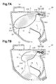
- FIG. 7A illustrates a developing cartridge in a third alternative embodiment according to one or more aspects of the disclosure.
- FIG. 7B illustrates how a developer is released from an opened developer bag in the third alternative embodiment according to one or more aspects of the disclosure.
- FIG. 8 illustrates a developing cartridge in a fourth alternative embodiment according to one or more aspects of the disclosure.
- FIG. 9A is an enlarged view illustrating a waste bag storage portion and its surrounding components in a fifth alternative embodiment according to one or more aspects of the disclosure.
- FIG. 9B is an enlarged view illustrating a waste bag storage portion and its surrounding components in a sixth alternative embodiment according to one or more aspects of the disclosure.
- FIG. 9C is an enlarged view illustrating a waste bag storage portion and its surrounding components in a seventh alternative embodiment according to one or more aspects of the disclosure.
- a developing cartridge 1 includes a housing 2 , a developing roller 3 , a supply roller 4 , a layer-thickness regulating blade 5 , an agitator 7 , a developer bag 20 , and a winding shaft 11 (as an example of a shaft).
- the developer bag 20 may store toner T (as an example of a developer) therein.
- the winding shaft 11 is fixed to the developer bag 20 , and movable to pull the developer bag and wind the developer bag therearound.
- the developing roller 3 is rotatably supported by the housing 2 .
- the developing roller 3 is disposed in contact with or near to a photosensitive drum 6 .
- the supply roller 4 is disposed in contact with the developing roller 3 .
- the supply roller 4 is configured to supply a developer to the developing roller 3 .
- the supply roller 4 is rotatably supported by the housing 2 .
- the layer-thickness regulating blade 5 has one end that is supported by the housing 2 , and the other end that is positioned in contact with the developing roller 3 .
- the developer bag 20 includes a bag portion 21 and a connecting portion 22 .
- the bag portion 21 stores toner T therein.
- the connecting portion 22 has one end that is connected to the bag portion 21 , and the other end that is connected to the winding shaft 11 .
- the developer bag 20 includes a bonded portion that may be a portion of the developer bag 20 .
- the developer bag 20 is sealed at the bonded portion to close an outlet for releasing toner T stored therein.
- the bonded portion is positioned at an end portion of the bag portion 21 to which the connecting portion 22 of the developer bag 20 is connected.
- the bonded portion is configured to separate from the end portion of the bag portion 21 by contact of the bag portion 21 to a squeeze portion 15 .
- the winding shaft 11 is rotatably supported by the housing 2 .
- the winding shaft 11 is disposed opposite to the developing roller 3 across the agitator 7 .
- the winding shaft 11 is disposed outside or out of a rotation path K of the agitator 7 within the housing 2 .
- the winding shaft 11 is configured to rotate in a direction to wind the developer bag 20 therearound from below, e.g., in a counterclockwise direction in FIG. 1 .
- the housing 2 includes a developer storage chamber 12 , a waste bag storage portion 13 , a handle 14 , and the squeeze portion 15 .
- the developer storage chamber 12 accommodates the developer bag 20 therein.
- the waste bag storage portion 13 is configured to store the developer bag 20 that has wound around the winding shaft 11 .
- the waste bag storage portion 13 protrudes outwardly relative to the developer storage chamber 12 in the housing 2 .
- the winding shaft 11 is disposed in the waste bag storage portion 13 .
- the waste bag storage portion 13 has a lower wall 13 A below the winding shaft 11 .
- the lower wall 13 A is downwardly inclined toward the developer storage chamber 12 .
- the lower wall 13 A is contiguous to inner wall surfaces defining the developer storage chamber 12 of the housing 2 .
- the entire portion of the lower wall 13 A is downwardly inclined toward the developer storage chamber 12 .
- the waste bag storage portion 13 has a relatively wide open entrance and is tapered toward the back from the entrance when viewed in a direction in which a rotation axis of the winding shaft 11 extends (i.e., the height of the waste bag storage portion 13 decreases gradually toward the back in FIG. 1 ). That is, the entrance of the waste bag storage portion 13 has the largest height. A lower end of the lower wall 13 A is spaced from the squeeze portion 15 .
- the handle 14 extends from an outer surface of the housing 2 and is a one piece with the housing 2 .
- the handle 14 is disposed near the winding shaft 11 rather than the developing roller 3 .
- the squeeze portion 15 includes a first portion 15 A, and a second portion 15 B that is spaced from the first portion 15 A by a predetermined distance.
- the squeeze portion 15 is disposed between the waste bag storage portion 13 and the bag portion 21 of the developer bag 20 that has not been wound around the winding shaft 11 .
- the squeeze portion 15 is positioned at the entrance of the waste bag storage portion 13 .
- a clearance between the first portion 15 A and the second portion 15 B, i.e., a height of an opening of the squeeze portion 15 is smaller than a maximum height of the waste bag storage portion 13 in a direction in which the first portion 15 A and the second portion 15 B face each other.
- the clearance between the first portion 15 A and the second portion 15 B is greater than a thickness of the developer bag 20 that has released toner T completely therefrom.
- the clearance between the first portion 15 A and the second portion 15 B may be equal to a thickness of a sheet member for the developer bag 20 plus 3 mm or less, preferably 2 mm or less, more preferably 1 mm or less.
- the first portion 15 A protrudes from an inner surface of an upper wall 2 A of the housing 2 .
- the first portion 15 A has a substantially rectangular shape when viewed in the axial direction of the winding shaft 11 .
- the second portion 15 B is a one piece with the housing 2 .
- the second portion 15 B has a substantially triangular shape when viewed in the axial direction of the winding shaft 11 .
- the second portion 15 B has corners, one of which is an acute corner 15 C situated on a farther side from the winding shaft 11 in a direction in which the squeeze portion 15 and the winding shaft 11 face each other.
- the connecting portion 22 of the developer bag 20 is connected to the winding shaft 11 while being positioned between the first portion 15 A and the second portion 15 B. In this state, the connecting portion 22 connects between the bag portion 21 and the winding shaft 11 .
- the agitator 7 may be a deformable sheet-shaped member.
- the agitator 7 is rotatably supported by the housing 2 .
- the agitator 7 is rotatably supported by the housing 2 via a rotating shaft 7 A.
- the rotating shaft 7 A has one end portion that is rotatably supported by a first bearing 19 A that may be a recess defined by inner wall surfaces of the housing 2 .
- the rotating shaft 7 A has the other end portion that is rotatably supported by a second bearing 19 B of the housing 2 .
- the other end portion of the rotating shaft 7 A extends to the outside of the housing 2 .
- a first gear 16 is fixed to the exposed end of the rotating shaft 7 A.
- the first gear 16 is configured to transmit a driving force to the rotating shaft 7 A from a motor (not illustrated) as a drive source.
- the first gear 16 is in mesh with a second gear 17 rotatably supported by the housing 2 .
- the winding shaft 11 extends in a direction along a direction in which a rotation axis of the agitator 7 extends.
- the winding shaft 11 has one end portion that is rotatably supported by a third bearing 19 C that may be a recess defined by inner wall surfaces of the housing 2 .
- the winding shaft 11 has the other end portion that is rotatably supported by a fourth bearing 19 D of the housing 2 .
- the other end portion of the winding shaft 11 extends to the outside of the housing 2 .
- a third gear 18 is fixed to the exposed end of the winding shaft 11 .
- the third gear 18 is in mesh with the second gear 17 .
- the third gear 18 is configured to transmit a driving force received from the drive source via the first gear 16 and the second gear 17 to the winding shaft 11 .
- the developer bag 20 including the bag portion 21 and the connecting portion 22 is formed by a folded sheet member.
- the sheet member is folded to make a crease 21 C, and edge portions of the overlapping portions are bonded to each other using an adhesive B.
- an adhesive B By doing so, such a developer bag 20 may be formed.
- the bag portion 21 includes an upper portion 21 A and a lower portion 21 B that are contiguous to each other via the crease 21 C.
- the upper portion 21 A is bonded to the lower portion 21 B at three sides (e.g., edge portions 21 D) other than the crease 21 C.
- an end portion 21 E of the lower portion 21 B situated close to the connecting portion 22 is folded back toward the inside of the bag portion 21 .
- the end portion 21 E has a surface 21 F (e.g., an upper surface in FIG. 3B ) that extends contiguously from an external surface of the lower portion 21 B.
- the surface 21 F of the end portion 21 E is bonded to a lower surface of the upper portion 21 A by an adhesive B.
- the portion (e.g., the surface 21 F) of the end portion 21 E bonded to the upper portion 21 A using the adhesive B may be a bonded portion where a portion of the developer bag 20 is bonded to another portion of the developer bag 20 to close the outlet for releasing toner T stored in the developer bag 20 therefrom.
- the bonded portion is positioned at the end portion of the bag portion 21 where the connection portion 22 is connected to.
- the bonded portion is configured to separate from the lower surface of the upper portion 21 A by contact of the bag portion 21 and the squeeze portion 15 .
- the sheet member used for the developer bag 20 may be made of metallic materials, e.g., aluminum, or resin materials, e.g., polyethylene terephthalate (“PET”), polyethylene (“PE”), or polypropylene (“PP).
- metallic materials e.g., aluminum
- resin materials e.g., polyethylene terephthalate (“PET”), polyethylene (“PE”), or polypropylene (“PP).
- the winding shaft 11 rotates counterclockwise in synchronization with the rotation of the agitator 7 .
- the connecting portion 22 fixed to the winding shaft 11 is wound around the winding shaft 11 from below.
- the bag portion 21 is pulled toward the winding shaft 11 to contact the squeeze portion 15 .
- the corner 15 C of the second portion 15 B strongly contacts the vicinity of the end portion 21 E of the bag portion 21 to remove the end portion 21 E from the upper portion 21 A downward.
- the bonded portion separates from the upper portion 21 A and therefore the outlet (as an example of an opening) for releasing toner T from the developer bag 20 to the developer storage chamber 12 appears.
- Toner T released to the developer storage chamber 12 is supplied to the supply roller 4 .
- the supply roller 4 then supplies toner T to the developing roller 3 by rotating in contact with the developing roller 3 .
- the layer-thickness regulating blade 5 regulates a layer thickness of toner T held by the developing roller 3 . Thereafter, toner T is supplied onto a circumferential surface of the photosensitive drum 6 .
- the sealed developer bag 20 is opened by first rotation of the winding shaft 11 disposed in the housing 2 . Therefore, the developer bag 20 may be sealed to store toner T therein until first use of the developing cartridge 1 . That is, toner T may be released from the developer bag 20 at the first use of the developing cartridge 1 .
- this configuration may eliminate a user's operation for opening the developer bag 20 when the developing cartridge 1 is first used, and may also reduce or prevent leakage of toner T to the outside of the housing 2 .
- toner T is stored in the sealed developer bag 20 until immediately before the developing cartridge 1 is first used, which may reduce deterioration of toner T. Therefore, toner T may have a long use life.
- toner T may be squeezed out from the developer bag 20 . While the developer bag 20 passes therethrough, toner T adhering to the interior surface of the developer bag 20 may also be scraped therefrom. Therefore, this configuration may minimize residual toner T on the interior surface of the developer bag 20 .
- Providing the squeeze portion 15 at the entrance of the waste bag storage portion 13 may enable the rolled developer bag 20 to be kept in the waste bag storage portion 13 without allowing the developer bag 20 to return to the developer storage chamber 12 .
- the winding shaft 11 is disposed outside or out of the rotation path K of the agitator 7 . Therefore, the winding shaft 11 may fail to interfere with the agitator 7 .
- the developer bag 20 wound around the winding shaft 11 may also fail to interfere with the agitator 7 . Therefore, toner T released to and stored in the developer storage chamber 12 may be agitated by the agitator 7 and supplied to the developing roller 3 by the agitator 7 effectively.
- the winding shaft 11 is disposed opposite to the developing roller 3 across the agitator 7 .
- the developer bag 20 wound around the winding shaft 11 may fail to interfere with the developing roller 3 and the supply roller 4 adjacent to the developing roller 3 . Therefore, toner T released to and stored in the developer storage chamber 12 may be supplied to the developing roller 3 effectively.
- the waste bag storage portion 13 protrudes outwardly relative to the developer storage chamber 12 in the housing 2 .
- the rolled developer bag 20 stored in the waste bag storage portion 13 may fail to interfere with operation by the agitator 7 , such as agitation of toner T by the agitator 7 or supply of toner T to the developing roller 3 by the agitator 7 .
- the developer bag 20 returns to the sheet member after completely releasing toner T therefrom. Therefore, the winding shaft 11 may roll up the developer bag 20 compactly, and toner T remaining on the interior surface of the developer bag 20 may be reduced to a minimum. In addition, toner T adhering the interior surface of the developer bag 20 (e.g., the sheet member) may be scraped therefrom by the squeeze portion 15 .
- the developer bag 20 is wound around the winding shaft 11 from below. With this configuration, when the winding shaft 11 rolls up the developer bag 20 therearound, toner T may be removed from the lower surface (e.g., the interior surface) of the upper portion 21 A of the bag portion 21 at the squeeze portion 15 . Thus, the developer bag 20 may be wound with minimum toner T remaining thereto.
- the end portion 21 E of the lower portion 21 B is gradually peeled from the upper portion 21 A, which may enable a force of pulling the developer bag 20 to be smaller. Therefore, this configuration may further enable a driving force of the drive source to be smaller.
- the handle 14 is disposed near the winding shaft 11 rather than the developing roller 3 . Therefore, when the user attaches or detaches the developing cartridge 1 to or from the image forming apparatus by holding the handle 14 , this configuration may eliminate an accidental touch to the developing roller 3 by the user.
- the waste bag storage portion 13 protrudes horizontally relative to the developer storage chamber 12 in the housing 2 .
- a bag storage portion may protrude vertically (e.g., upward) relative to the developer storage chamber in the housing.
- a developing cartridge 30 includes a bag storage portion 31 protruding upward relative to the developer storage chamber 12 in the housing 2 .
- the winding shaft 11 is disposed in the upwardly-protruding waste bag storage portion 31 .
- a squeeze portion 35 including a first portion 35 A and a second portion 35 B is disposed below the winding shaft 11 .
- the first portion 35 A and the second portion 35 B each have a triangular shape when viewed in direction in which the rotation axis of the winding shaft 11 extends.
- the first portion 35 A and the second portion 35 B each have an inclined upper surface.
- the waste bag storage portion 31 has no partition (e.g., a lower wall) for dividing the waste bag storage portion 31 and the developer storage chamber 12 .
- this configuration may also enable release of toner T from the developer bag 20 within the developing cartridge 30 and storage of the rolled developer bag 20 in the waste bag storage portion 31 .
- the waste bag storage portion 31 protrudes upward and has no lower wall. Therefore, toner T intruding the waste bag storage portion 31 may fall down to return to the developer storage chamber 12 .
- each of the first portion 35 A and the second portion 35 B of the squeeze portion 35 has the inclined upper surface. This configuration may reduce accumulation of toner T falling on the first portion 35 A and the second portion 35 B from the waste bag storage portion 31 .
- the developer bag 20 is opened by peeling off the bonded portion bonded using the adhesive B.
- a developer bag may have an easy-to-tear portion at which the developer bag may tear easily as compared with the other portions thereof.
- a developer bag 40 includes a bag portion 41 storing toner T therein, and a connecting portion 42 connecting between the winding shaft 11 and the bag portion 41 .
- the bag portion 41 includes a cylindrical portion 41 A and side portions 41 B. The side portions 41 B close ends of the cylindrical portion 41 A.
- the bag portion 41 has first perforations 43 and second perforations 44 , which are an example of the easy-to-tear portion.
- the first perforations 43 align along an end portion of the bag portion 41 where the connecting portion 42 is connected to.
- the second perforations 44 extend from each end of the line of the first perforations 43 and align along a circumferential direction of the cylindrical portion 41 A.
- this configuration may also enable the bag portion 41 to be opened to release toner T therefrom in response to winding of the developer bag 40 around the winding shaft 11 (not illustrated in FIG. 6 ). More specifically, the bag portion 41 is torn at the first perforations 43 to release toner T therefrom by contact of the first perforations 43 to the squeeze portion 15 in response to winding of the developer bag 40 around the winding shaft 11 .
- the squeeze portion 15 opens the developer bag 20 by removing a portion (e.g., the bonded portion) of the developer bag 20 from another portion thereof.
- a developer bag may have an outlet for releasing a developer and a developing cartridge may further include a seal member for closing the outlet. In this configuration, the developer bag may be opened by removing the seal member from the outlet.
- a developing cartridge 50 includes a developer bag 51 having an outlet 51 A, a seal member 52 , and the squeeze portion 15 .
- the seal member 52 has one end portion that closes the outlet 51 A to seal the developer bag 51 , and the other end portion that is fixed to one of the inner surfaces of the housing 2 of the developing cartridge 50 .
- the adhesive strength of the other end portion to the inner surface of the housing 2 is stronger than the adhesive strength of the one end portion to the developer bag 51 .
- this configuration may also enable the bag portion 51 to be opened to release toner T therefrom by rotation of the winding shaft 11 .
- the waste developer bag 51 may fail to interfere with operation by the agitator 7 , such as agitation of toner T by the agitator 7 or supply of toner T to the developing roller 3 by the agitator 7 .
- the winding shaft 11 extends along the direction in which the rotating shaft 7 A of the agitator 7 extends. Nevertheless, in other embodiments, for example, a winding shaft may extend in a direction orthogonal to the direction in which the rotating shaft of the agitator extends.
- a developing cartridge 60 includes a winding shaft 61 that extends in a direction orthogonal to a rotating axis L of the agitator 7 .
- the developer bag 65 is connected to the winding shaft 61 .
- this configuration may also enable the winding shaft 61 to roll up the developer bag 65 that has released toner T therefrom completely. Therefore, the rolled developer bag 65 may fail to interfere with operation of the developing cartridge 60 .
- the squeeze portion 15 has the opening (e.g., the clearance between the first portion 15 A and the second portion 15 B) therein.
- a squeeze portion may be configured to pinch a developer bag.
- a waste bag storage portion 70 includes a squeeze portion 71 at its entrance.
- the squeeze portion 71 may be made of sponge.
- the waste bag storage portion 70 is configured to pinch a connecting portion 51 D of the developer bag 51 .
- the squeeze portion 71 includes a first portion 71 A and a second portion 71 B, each of which is fixed to the housing 2 .
- the first portion 71 A and the second portion 71 B pinch the developer bag 51 therebetween. Therefore, in response to rolling up of the connecting portion 51 D by the winding shaft 11 , toner T remaining in the developer bag 51 is squeezed therefrom by elastic force of the sponges. According to the fifth alternative embodiment, this configuration may therefore minimize residual toner T in the developer bag 51 .
- a squeeze portion may pinch the connecting portion 51 D using an urging member.
- a squeeze portion 81 is disposed at an entrance of a waste bag storage portion 80 and includes a first portion 81 A, a second portion 81 B, and an urging member 81 C.
- the first portion 81 A is supported by the housing 2 and is configured to move in a direction in which the first portion 81 A moves closer to and away from the second portion 81 B.
- the urging member 81 C urges the first portion 81 A toward the second portion 81 B.
- the second portion 81 B is fixedly supported by the housing 2 .
- the first portion 81 A is urged toward the second portion 81 B.
- the first portion 81 A and the second portion 81 B pinch the developer bag 51 therebetween. Therefore, this configuration may also enable remaining toner T to be squeezed out of the developer bag 51 , and minimize residual toner T on the interior surface of the developer bag 51 (also refer to FIG. 7 ).
- the squeeze portion 15 includes the first portion 15 A and the second portion 15 B that is spaced from the upper wall 2 of the housing 2 .
- the configuration of the squeeze portion might not be limited to the specific example.
- a squeeze portion 91 includes a protruding wall and the lower wall 13 A of the waste bag storage portion 13 .
- the protruding wall extends from the upper wall 2 A of the housing 2 toward the lower wall 13 A of the waste bag storage portion 13 .
- a distal end of the protruding wall of the squeeze portion 91 is spaced from the lower wall 13 A by a predetermined distance.
- the connecting portion 22 of the developer bag 20 is connected to the winding shaft 11 through between the protruding wall of the squeeze portion 91 and the lower wall 13 A.
- this configuration may also enable remaining toner T to be squeezed out of the developer bag 20 , and minimize residual toner T on the interior surface of the developer bag 20 (also refer to FIG. 1 ).
- the winding shaft 11 is driven by the motor. Nevertheless, in other embodiments, for example, the winding shaft may be rotated manually.
- the developer bag 20 consists of a single sheet member. Nevertheless, in other embodiments, for example, a developer bag may consist of a plurality of sheet members, e.g., two or more sheet members.
Landscapes
- Physics & Mathematics (AREA)
- General Physics & Mathematics (AREA)
- Dry Development In Electrophotography (AREA)
- Wet Developing In Electrophotography (AREA)
Applications Claiming Priority (2)
| Application Number | Priority Date | Filing Date | Title |
|---|---|---|---|
| JP2016-070707 | 2016-03-31 | ||
| JP2016070707A JP6733265B2 (ja) | 2016-03-31 | 2016-03-31 | 現像カートリッジ |
Publications (2)
| Publication Number | Publication Date |
|---|---|
| US20170285523A1 US20170285523A1 (en) | 2017-10-05 |
| US10073377B2 true US10073377B2 (en) | 2018-09-11 |
Family
ID=59958704
Family Applications (1)
| Application Number | Title | Priority Date | Filing Date |
|---|---|---|---|
| US15/472,594 Active US10073377B2 (en) | 2016-03-31 | 2017-03-29 | Developing cartridge |
Country Status (3)
| Country | Link |
|---|---|
| US (1) | US10073377B2 (ja) |
| JP (1) | JP6733265B2 (ja) |
| CN (1) | CN107272369B (ja) |
Families Citing this family (4)
| Publication number | Priority date | Publication date | Assignee | Title |
|---|---|---|---|---|
| US10108105B2 (en) * | 2016-04-13 | 2018-10-23 | Canon Kabushiki Kaisha | Developing apparatus and image forming apparatus |
| JP7091092B2 (ja) * | 2018-03-07 | 2022-06-27 | キヤノン株式会社 | 現像装置 |
| JP7501150B2 (ja) | 2020-06-25 | 2024-06-18 | 株式会社リコー | 粉体収容装置、現像装置、プロセスカートリッジ、及び、画像形成装置 |
| JP7778556B2 (ja) * | 2021-08-31 | 2025-12-02 | キヤノン株式会社 | 画像形成装置 |
Citations (6)
| Publication number | Priority date | Publication date | Assignee | Title |
|---|---|---|---|---|
| US3501065A (en) * | 1968-05-01 | 1970-03-17 | Eastman Kodak Co | Container and dispensing mechanism for toner powder |
| US3561647A (en) * | 1968-05-01 | 1971-02-09 | Eastman Kodak Co | Apparatus for handling electrographic toner packages |
| US4766457A (en) * | 1987-09-02 | 1988-08-23 | Xerox Corporation | Particulate material dispenser |
| US5075727A (en) * | 1989-09-29 | 1991-12-24 | Kabushiki Kaisha Toshiba | Developing device for image forming apparatus |
| US6178302B1 (en) * | 1997-12-09 | 2001-01-23 | Canon Kabushiki Kaisha | Developer container seal, developer container, developing apparatus, process cartridge, and image forming apparatus |
| US20130336679A1 (en) | 2012-06-15 | 2013-12-19 | Canon Kabushiki Kaisha | Developer containing unit, process cartridge, and electrophotographic image forming apparatus |
Family Cites Families (22)
| Publication number | Priority date | Publication date | Assignee | Title |
|---|---|---|---|---|
| JPS58163979A (ja) * | 1982-03-24 | 1983-09-28 | Ricoh Co Ltd | トナ−回収装置 |
| JPH0760289B2 (ja) * | 1986-09-30 | 1995-06-28 | 三田工業株式会社 | 画像形成装置の寿命表示装置 |
| JPH01166363U (ja) * | 1988-05-10 | 1989-11-21 | ||
| JPH0324665U (ja) * | 1989-07-19 | 1991-03-14 | ||
| JP2907625B2 (ja) * | 1992-02-03 | 1999-06-21 | キヤノン株式会社 | 現像剤補給容器 |
| JPH0683190A (ja) * | 1992-09-01 | 1994-03-25 | Brother Ind Ltd | 画像形成装置のプロセスユニット |
| JPH06149026A (ja) * | 1992-11-05 | 1994-05-27 | Tokyo Electric Co Ltd | 現像装置 |
| US5402216A (en) * | 1992-12-28 | 1995-03-28 | Mita Industrial Co., Ltd. | Mechanism for opening/closing a toner falling aperture |
| JP3141370B2 (ja) * | 1993-05-25 | 2001-03-05 | 船井電機株式会社 | 現像剤パック構造 |
| JP3172070B2 (ja) * | 1995-11-29 | 2001-06-04 | 京セラミタ株式会社 | トナーカートリッジ |
| JPH1184807A (ja) * | 1997-06-30 | 1999-03-30 | Canon Inc | 電子写真画像形成装置 |
| JP4648046B2 (ja) * | 2005-03-22 | 2011-03-09 | リンテック株式会社 | ラベルプリンタ |
| US7758173B2 (en) * | 2005-12-23 | 2010-07-20 | Xerox Corporation | Collapsible packaging system |
| CN101391715B (zh) * | 2007-09-19 | 2012-07-11 | 柯尼卡美能达商用科技株式会社 | 粘带粘贴装置,以及向薄膜部件的粘带粘贴方法 |
| JP2012208493A (ja) * | 2011-03-16 | 2012-10-25 | Ricoh Co Ltd | 粉体収容容器、プロセスカートリッジ及び画像形成装置 |
| JP5420025B2 (ja) * | 2011-07-14 | 2014-02-19 | キヤノン株式会社 | 現像剤収納ユニット、プロセスカートリッジ、電子写真画像形成装置 |
| JP2014041256A (ja) * | 2012-08-22 | 2014-03-06 | Ricoh Co Ltd | 粉体補給装置、プロセスカートリッジおよび画像形成装置 |
| JP6218493B2 (ja) * | 2012-09-06 | 2017-10-25 | キヤノン株式会社 | ユニット、ユニットの製造方法、及び画像形成装置、画像形成装置の製造方法 |
| JP2015132745A (ja) * | 2014-01-15 | 2015-07-23 | キヤノン株式会社 | 現像剤収納ユニット、プロセスカートリッジ及び画像形成装置 |
| JP6381222B2 (ja) * | 2014-02-18 | 2018-08-29 | キヤノン株式会社 | 現像剤収納ユニット及びその製造方法、現像装置、プロセスカートリッジ及び画像形成装置 |
| JP2016024330A (ja) * | 2014-07-18 | 2016-02-08 | 株式会社リコー | トナー収容容器、トナーカートリッジ、トナー補給装置、プロセスカートリッジ及び画像形成装置 |
| JP6406928B2 (ja) * | 2014-08-29 | 2018-10-17 | キヤノン株式会社 | 現像剤容器、現像剤収納ユニット、プロセスカートリッジおよび画像形成装置 |
-
2016
- 2016-03-31 JP JP2016070707A patent/JP6733265B2/ja active Active
-
2017
- 2017-03-22 CN CN201710173383.6A patent/CN107272369B/zh active Active
- 2017-03-29 US US15/472,594 patent/US10073377B2/en active Active
Patent Citations (8)
| Publication number | Priority date | Publication date | Assignee | Title |
|---|---|---|---|---|
| US3501065A (en) * | 1968-05-01 | 1970-03-17 | Eastman Kodak Co | Container and dispensing mechanism for toner powder |
| US3561647A (en) * | 1968-05-01 | 1971-02-09 | Eastman Kodak Co | Apparatus for handling electrographic toner packages |
| US4766457A (en) * | 1987-09-02 | 1988-08-23 | Xerox Corporation | Particulate material dispenser |
| US5075727A (en) * | 1989-09-29 | 1991-12-24 | Kabushiki Kaisha Toshiba | Developing device for image forming apparatus |
| US6178302B1 (en) * | 1997-12-09 | 2001-01-23 | Canon Kabushiki Kaisha | Developer container seal, developer container, developing apparatus, process cartridge, and image forming apparatus |
| US20130336679A1 (en) | 2012-06-15 | 2013-12-19 | Canon Kabushiki Kaisha | Developer containing unit, process cartridge, and electrophotographic image forming apparatus |
| JP2014016592A (ja) | 2012-06-15 | 2014-01-30 | Canon Inc | 現像剤収納ユニット、プロセスカートリッジ、電子写真画像形成装置 |
| US9063464B2 (en) | 2012-06-15 | 2015-06-23 | Canon Kabushiki Kaisha | Developer containing unit, process cartridge, and electrophotographic image forming apparatus |
Also Published As
| Publication number | Publication date |
|---|---|
| CN107272369A (zh) | 2017-10-20 |
| JP2017181875A (ja) | 2017-10-05 |
| US20170285523A1 (en) | 2017-10-05 |
| CN107272369B (zh) | 2021-05-07 |
| JP6733265B2 (ja) | 2020-07-29 |
Similar Documents
| Publication | Publication Date | Title |
|---|---|---|
| US10073377B2 (en) | Developing cartridge | |
| RU2584178C2 (ru) | Вмещающий девелопер блок, технологический картридж и электрофотографическое устройство формирования изображения | |
| EP2786210B1 (en) | Developer accommodating container, process cartridge and electrophotographic image forming apparatus | |
| JP2010217834A (ja) | トナー容器 | |
| US6484000B1 (en) | Sealing member which prevents contamination when removed and container having the sealing member | |
| EP3492993A1 (en) | Developer accommodating member, developer accommodating unit, developing device, process cartridge and image forming apparatus | |
| JP2014041256A (ja) | 粉体補給装置、プロセスカートリッジおよび画像形成装置 | |
| JP2003005517A (ja) | 現像装置 | |
| US5194900A (en) | Developer cartridge having easily removable sealing material | |
| JP3071850B2 (ja) | 容器装置 | |
| JPH03118569A (ja) | トナーカートリッジとそのトナーカートリッジによるトナー補給装置 | |
| JPH09197792A (ja) | 現像装置及びプロセスカートリッジ | |
| JPH01250975A (ja) | 現像器 | |
| JP2612031B2 (ja) | トナーカートリッジ | |
| JP2015203847A (ja) | 現像剤収納ユニット及びこれを備えたプロセスカートリッジ、画像形成装置 | |
| JP2611312B2 (ja) | 現像剤補給容器 | |
| JPH0439074B2 (ja) | ||
| JP3288219B2 (ja) | 現像剤補給容器 | |
| JP2000029293A (ja) | 現像剤収容容器 | |
| JP2004240338A (ja) | 現像装置及びこれを備えたプロセスカートリッジ | |
| JP4208521B2 (ja) | 現像剤補給容器 | |
| JP2004205608A (ja) | 現像装置、プロセスカートリッジ及び画像形成装置 | |
| JPH079166Y2 (ja) | 画像形成ユニツト | |
| JPS60104971A (ja) | トナ−補給装置 | |
| WO2016204245A1 (ja) | トナー補給方法、トナーカートリッジの製造方法、及びトナーカートリッジ |
Legal Events
| Date | Code | Title | Description |
|---|---|---|---|
| AS | Assignment |
Owner name: BROTHER KOGYO KABUSHIKI KAISHA, JAPAN Free format text: ASSIGNMENT OF ASSIGNORS INTEREST;ASSIGNOR:ITABASHI, NAO;REEL/FRAME:041786/0553 Effective date: 20170131 |
|
| STCF | Information on status: patent grant |
Free format text: PATENTED CASE |
|
| MAFP | Maintenance fee payment |
Free format text: PAYMENT OF MAINTENANCE FEE, 4TH YEAR, LARGE ENTITY (ORIGINAL EVENT CODE: M1551); ENTITY STATUS OF PATENT OWNER: LARGE ENTITY Year of fee payment: 4 |
|
| MAFP | Maintenance fee payment |
Free format text: PAYMENT OF MAINTENANCE FEE, 8TH YEAR, LARGE ENTITY (ORIGINAL EVENT CODE: M1552); ENTITY STATUS OF PATENT OWNER: LARGE ENTITY Year of fee payment: 8 |