JP2007287381A - 電気部品用ソケット - Google Patents
電気部品用ソケット Download PDFInfo
- Publication number
- JP2007287381A JP2007287381A JP2006110799A JP2006110799A JP2007287381A JP 2007287381 A JP2007287381 A JP 2007287381A JP 2006110799 A JP2006110799 A JP 2006110799A JP 2006110799 A JP2006110799 A JP 2006110799A JP 2007287381 A JP2007287381 A JP 2007287381A
- Authority
- JP
- Japan
- Prior art keywords
- contact
- biting
- socket
- contact pin
- hole
- Prior art date
- Legal status (The legal status is an assumption and is not a legal conclusion. Google has not performed a legal analysis and makes no representation as to the accuracy of the status listed.)
- Granted
Links
- 230000036316 preload Effects 0.000 claims description 17
- 238000009434 installation Methods 0.000 abstract 1
- 238000003825 pressing Methods 0.000 description 10
- 229910000679 solder Inorganic materials 0.000 description 10
- 230000015572 biosynthetic process Effects 0.000 description 7
- 230000001105 regulatory effect Effects 0.000 description 3
- 238000005452 bending Methods 0.000 description 2
- 230000000694 effects Effects 0.000 description 2
- 238000003780 insertion Methods 0.000 description 2
- 230000037431 insertion Effects 0.000 description 2
- 238000000034 method Methods 0.000 description 2
- 238000004080 punching Methods 0.000 description 2
- 239000004065 semiconductor Substances 0.000 description 2
- 238000013459 approach Methods 0.000 description 1
- 239000004020 conductor Substances 0.000 description 1
- 238000005520 cutting process Methods 0.000 description 1
- 238000007689 inspection Methods 0.000 description 1
- 238000004519 manufacturing process Methods 0.000 description 1
- 238000000926 separation method Methods 0.000 description 1
- 238000004904 shortening Methods 0.000 description 1
- 238000009751 slip forming Methods 0.000 description 1
- 238000003860 storage Methods 0.000 description 1
- 239000000758 substrate Substances 0.000 description 1
Images


Classifications
-
- G—PHYSICS
- G01—MEASURING; TESTING
- G01R—MEASURING ELECTRIC VARIABLES; MEASURING MAGNETIC VARIABLES
- G01R1/00—Details of instruments or arrangements of the types included in groups G01R5/00 - G01R13/00 and G01R31/00
- G01R1/02—General constructional details
- G01R1/04—Housings; Supporting members; Arrangements of terminals
- G01R1/0408—Test fixtures or contact fields; Connectors or connecting adaptors; Test clips; Test sockets
- G01R1/0433—Sockets for IC's or transistors
- G01R1/0441—Details
- G01R1/0466—Details concerning contact pieces or mechanical details, e.g. hinges or cams; Shielding
-
- G—PHYSICS
- G01—MEASURING; TESTING
- G01R—MEASURING ELECTRIC VARIABLES; MEASURING MAGNETIC VARIABLES
- G01R1/00—Details of instruments or arrangements of the types included in groups G01R5/00 - G01R13/00 and G01R31/00
- G01R1/02—General constructional details
- G01R1/04—Housings; Supporting members; Arrangements of terminals
- G01R1/0408—Test fixtures or contact fields; Connectors or connecting adaptors; Test clips; Test sockets
-
- H—ELECTRICITY
- H01—ELECTRIC ELEMENTS
- H01R—ELECTRICALLY-CONDUCTIVE CONNECTIONS; STRUCTURAL ASSOCIATIONS OF A PLURALITY OF MUTUALLY-INSULATED ELECTRICAL CONNECTING ELEMENTS; COUPLING DEVICES; CURRENT COLLECTORS
- H01R13/00—Details of coupling devices of the kinds covered by groups H01R12/70 or H01R24/00 - H01R33/00
- H01R13/02—Contact members
- H01R13/04—Pins or blades for co-operation with sockets
- H01R13/05—Resilient pins or blades
-
- H—ELECTRICITY
- H01—ELECTRIC ELEMENTS
- H01R—ELECTRICALLY-CONDUCTIVE CONNECTIONS; STRUCTURAL ASSOCIATIONS OF A PLURALITY OF MUTUALLY-INSULATED ELECTRICAL CONNECTING ELEMENTS; COUPLING DEVICES; CURRENT COLLECTORS
- H01R13/00—Details of coupling devices of the kinds covered by groups H01R12/70 or H01R24/00 - H01R33/00
- H01R13/02—Contact members
- H01R13/193—Means for increasing contact pressure at the end of engagement of coupling part, e.g. zero insertion force or no friction
-
- H—ELECTRICITY
- H01—ELECTRIC ELEMENTS
- H01R—ELECTRICALLY-CONDUCTIVE CONNECTIONS; STRUCTURAL ASSOCIATIONS OF A PLURALITY OF MUTUALLY-INSULATED ELECTRICAL CONNECTING ELEMENTS; COUPLING DEVICES; CURRENT COLLECTORS
- H01R13/00—Details of coupling devices of the kinds covered by groups H01R12/70 or H01R24/00 - H01R33/00
- H01R13/40—Securing contact members in or to a base or case; Insulating of contact members
- H01R13/42—Securing in a demountable manner
- H01R13/428—Securing in a demountable manner by resilient locking means on the contact members; by locking means on resilient contact members
-
- H—ELECTRICITY
- H01—ELECTRIC ELEMENTS
- H01R—ELECTRICALLY-CONDUCTIVE CONNECTIONS; STRUCTURAL ASSOCIATIONS OF A PLURALITY OF MUTUALLY-INSULATED ELECTRICAL CONNECTING ELEMENTS; COUPLING DEVICES; CURRENT COLLECTORS
- H01R2201/00—Connectors or connections adapted for particular applications
- H01R2201/20—Connectors or connections adapted for particular applications for testing or measuring purposes
Landscapes
- Physics & Mathematics (AREA)
- General Physics & Mathematics (AREA)
- Engineering & Computer Science (AREA)
- Computer Hardware Design (AREA)
- Microelectronics & Electronic Packaging (AREA)
- Testing Of Individual Semiconductor Devices (AREA)
- Connecting Device With Holders (AREA)
- Measuring Leads Or Probes (AREA)
Abstract
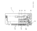
【解決手段】先端側に電気部品の端子12bに接触する接触部15cが形成され、貫通孔14dに挿通、配設されたコンタクトピン15とを備え、コンタクトピン15は、ソケット本体に固定される固定部15eと、上方に延びた板状の弾性片15bとを有し、コンタクトピン15の接触部15cが端子12bに対して、その板幅方向に弾性変形可能に形成され、固定部15eと接触部15cとの間に板幅方向の板面に沿って突出してソケット本体14の貫通孔14dの内壁に食込む食込部15fを有し、食込部15fが内壁の食込み部位14hに食込んだ状態では、コンタクトピン15の上下方向の移動を規制すると同時に、内壁が食込部15fを押圧することにより弾性片15bに接触部15cが閉じる方向に予圧を与えるように構成した。
【選択図】図5
Description
[発明の実施の形態1]
[発明の実施の形態2]
12 ICパッケージ(電気部品)
12b 半田ボール(端子)
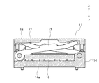
14 ソケット本体
14d 貫通孔
14f 収容部
14h 食込み部位
14i 案内面
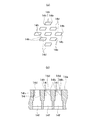
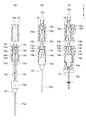
15 コンタクトピン
15a リード部
15b 弾性片
15c 接触部
15d 作動部
15e 固定部
15f 食込部
15g 突部
16 移動部材
16a 貫通孔
Claims (7)
- ソケット本体と、先端側に電気部品の端子に接触する接触部が形成され、前記ソケット本体の貫通孔に挿通されて配設されたコンタクトピンとを備えた電気部品用ソケットにおいて、
前記コンタクトピンは、前記ソケット本体に固定される固定部と、該固定部から上方に延びた板状の弾性片とを有し、
前記固定部は、前記ソケット本体の貫通孔に挿入された状態で固定され、
前記コンタクトピンの弾性片は、前記コンタクトピンの接触部が前記端子に対して離接可能となるように、その板幅方向に弾性変形可能に形成され、前記固定部と前記接触部との間に板幅方向の板面に沿って突出して前記ソケット本体の前記貫通孔の内壁に食込む食込部を有し、
前記内壁には、前記食込部が食込む食込み部位形成され、
前記食込部が前記内壁の前記食込み部位に食込んだ状態では、前記コンタクトピンの上下方向への移動を規制すると同時に、前記内壁が前記食込部を押圧することにより前記弾性片に前記接触部が閉じる方向に予圧を与えるように構成されたことを特徴とする電気部品用ソケット。 - 前記ソケット本体の上側には、前記ソケット本体に対して移動可能な移動部材が配設され、前記コンタクトピンの弾性片には、前記移動部材の貫通孔内に挿入され、該移動部材の移動時に押圧される作動部が設けられ、該作動部と前記食込部とが反対の方向に突出していることを特徴とする請求項1に記載の電気部品用ソケット。
- 前記移動部材は、前記ソケット本体に対して上下動可能に配設され、該移動部材の下降時に前記コンタクトピンの前記作動部を押圧するように構成されていることを特徴とする請求項2に記載の電気部品用ソケット。
- 前記ソケット本体の貫通孔は、該貫通孔に下方から前記コンタクトピンをその先端の接触部側から挿入可能であると共に、前記固定部の上端が当接する当接部を有し、該当接部に前記固定部の上端が当接することにより前記コンタクトピンの上方への移動が規制されるように構成されたことを特徴とする請求項1乃至3の何れか一つに記載の電気部品用ソケット。
- 前記食込み部位の下部には、前記コンタクトピン挿入時に前記食込部が摺接しながら移動する案内面が形成されており、該案内面は、前記食込み部位の下部から上部に向け、前記ソケット本体の貫通孔の対向する内壁までの間隔を狭くするように形成されていることを特徴とする請求項1乃至は4の何れか一つに記載の電気部品用ソケット。
- 前記弾性片は、板面が互いに対向するように一対設けられていることを特徴とする請求項1乃至は5の何れか一つに記載の電気部品用ソケット。
- 前記一対の弾性片は、前記食込部近傍及び前記作動部近傍の少なくとも一方に、相手の対向面に摺接する突部が少なくとも一方の面から形成されていることを特徴とする請求項6に記載の電気部品用ソケット。
Priority Applications (4)
| Application Number | Priority Date | Filing Date | Title |
|---|---|---|---|
| JP2006110799A JP4767741B2 (ja) | 2006-04-13 | 2006-04-13 | 電気部品用ソケット |
| US11/697,444 US7407388B2 (en) | 2006-04-13 | 2007-04-06 | Socket for testing electrical parts |
| DE102007017059.0A DE102007017059B4 (de) | 2006-04-13 | 2007-04-11 | Sockel für elektrische Bauteile |
| GB0707124A GB2437178B (en) | 2006-04-13 | 2007-04-13 | Socket for electrical parts |
Applications Claiming Priority (1)
| Application Number | Priority Date | Filing Date | Title |
|---|---|---|---|
| JP2006110799A JP4767741B2 (ja) | 2006-04-13 | 2006-04-13 | 電気部品用ソケット |
Publications (3)
| Publication Number | Publication Date |
|---|---|
| JP2007287381A true JP2007287381A (ja) | 2007-11-01 |
| JP2007287381A5 JP2007287381A5 (ja) | 2009-03-12 |
| JP4767741B2 JP4767741B2 (ja) | 2011-09-07 |
Family
ID=38116656
Family Applications (1)
| Application Number | Title | Priority Date | Filing Date |
|---|---|---|---|
| JP2006110799A Active JP4767741B2 (ja) | 2006-04-13 | 2006-04-13 | 電気部品用ソケット |
Country Status (4)
| Country | Link |
|---|---|
| US (1) | US7407388B2 (ja) |
| JP (1) | JP4767741B2 (ja) |
| DE (1) | DE102007017059B4 (ja) |
| GB (1) | GB2437178B (ja) |
Cited By (1)
| Publication number | Priority date | Publication date | Assignee | Title |
|---|---|---|---|---|
| JP2017072514A (ja) * | 2015-10-08 | 2017-04-13 | 三菱電機株式会社 | 大電流通電装置 |
Families Citing this family (4)
| Publication number | Priority date | Publication date | Assignee | Title |
|---|---|---|---|---|
| JP4802059B2 (ja) | 2006-07-27 | 2011-10-26 | 株式会社エンプラス | 電気部品用ソケット |
| KR101887071B1 (ko) * | 2016-09-01 | 2018-09-10 | 리노공업주식회사 | 검사장치의 슬라이더 조작기구 |
| TWI758091B (zh) * | 2021-02-08 | 2022-03-11 | 鴻勁精密股份有限公司 | 測試機構、接合機構及其應用之測試設備 |
| CN116027255B (zh) * | 2023-03-27 | 2023-07-21 | 青岛高科通信股份有限公司 | 一种电能表通用定位压接装置 |
Citations (7)
| Publication number | Priority date | Publication date | Assignee | Title |
|---|---|---|---|---|
| JP2000021531A (ja) * | 1998-07-01 | 2000-01-21 | Enplas Corp | 電気部品用ソケット |
| JP2003068416A (ja) * | 2001-08-24 | 2003-03-07 | Enplas Corp | 電気部品用ソケット |
| JP2003178851A (ja) * | 2001-12-12 | 2003-06-27 | Enplas Corp | 電気部品用ソケット |
| JP2003187938A (ja) * | 2001-12-13 | 2003-07-04 | Yamaichi Electronics Co Ltd | Icソケット |
| JP2003303656A (ja) * | 2002-04-09 | 2003-10-24 | Enplas Corp | 電気部品用ソケット |
| JP2004103377A (ja) * | 2002-09-09 | 2004-04-02 | Yamaichi Electronics Co Ltd | Icソケット |
| JP2006127935A (ja) * | 2004-10-29 | 2006-05-18 | Enplas Corp | 電気部品用ソケット |
Family Cites Families (11)
| Publication number | Priority date | Publication date | Assignee | Title |
|---|---|---|---|---|
| US4077694A (en) * | 1975-06-24 | 1978-03-07 | Amp Incorporated | Circuit board connector |
| US4245877A (en) * | 1976-12-30 | 1981-01-20 | Burndy Corporation | Circuit package receptacle with movable base separation means |
| US4472017A (en) * | 1983-04-01 | 1984-09-18 | Essex Group, Inc. | Tab receptacle terminal |
| JPH07335350A (ja) * | 1994-06-07 | 1995-12-22 | Ueruzu Japan Kk | Icソケット |
| JP3193652B2 (ja) | 1996-12-26 | 2001-07-30 | 株式会社オートネットワーク技術研究所 | 雌端子 |
| JP3270716B2 (ja) * | 1997-07-04 | 2002-04-02 | 日本テキサス・インスツルメンツ株式会社 | ソケット及び半導体装置の取付方法 |
| EP0969710B1 (en) * | 1998-06-30 | 2007-02-21 | Enplas Corporation | Socket for electrical parts |
| US6371783B1 (en) * | 1998-07-01 | 2002-04-16 | Enplas Corporation | Socket for electrical parts and method of assembling the same |
| JP4087012B2 (ja) * | 1999-05-31 | 2008-05-14 | 株式会社エンプラス | 電気部品用ソケット |
| JP4251423B2 (ja) * | 2000-01-28 | 2009-04-08 | 株式会社センサータ・テクノロジーズジャパン | ソケット |
| JP2003157944A (ja) | 2001-11-21 | 2003-05-30 | Yamaichi Electronics Co Ltd | Icソケット |
-
2006
- 2006-04-13 JP JP2006110799A patent/JP4767741B2/ja active Active
-
2007
- 2007-04-06 US US11/697,444 patent/US7407388B2/en not_active Expired - Fee Related
- 2007-04-11 DE DE102007017059.0A patent/DE102007017059B4/de not_active Expired - Fee Related
- 2007-04-13 GB GB0707124A patent/GB2437178B/en not_active Expired - Fee Related
Patent Citations (7)
| Publication number | Priority date | Publication date | Assignee | Title |
|---|---|---|---|---|
| JP2000021531A (ja) * | 1998-07-01 | 2000-01-21 | Enplas Corp | 電気部品用ソケット |
| JP2003068416A (ja) * | 2001-08-24 | 2003-03-07 | Enplas Corp | 電気部品用ソケット |
| JP2003178851A (ja) * | 2001-12-12 | 2003-06-27 | Enplas Corp | 電気部品用ソケット |
| JP2003187938A (ja) * | 2001-12-13 | 2003-07-04 | Yamaichi Electronics Co Ltd | Icソケット |
| JP2003303656A (ja) * | 2002-04-09 | 2003-10-24 | Enplas Corp | 電気部品用ソケット |
| JP2004103377A (ja) * | 2002-09-09 | 2004-04-02 | Yamaichi Electronics Co Ltd | Icソケット |
| JP2006127935A (ja) * | 2004-10-29 | 2006-05-18 | Enplas Corp | 電気部品用ソケット |
Cited By (1)
| Publication number | Priority date | Publication date | Assignee | Title |
|---|---|---|---|---|
| JP2017072514A (ja) * | 2015-10-08 | 2017-04-13 | 三菱電機株式会社 | 大電流通電装置 |
Also Published As
| Publication number | Publication date |
|---|---|
| JP4767741B2 (ja) | 2011-09-07 |
| DE102007017059A1 (de) | 2007-10-31 |
| GB2437178B (en) | 2010-07-21 |
| US7407388B2 (en) | 2008-08-05 |
| GB2437178A (en) | 2007-10-17 |
| DE102007017059B4 (de) | 2019-07-18 |
| US20070243727A1 (en) | 2007-10-18 |
| GB0707124D0 (en) | 2007-05-23 |
Similar Documents
| Publication | Publication Date | Title |
|---|---|---|
| JP4802059B2 (ja) | 電気部品用ソケット | |
| US8342872B2 (en) | Socket having two plates for holding contact pins and an urging member for urging the plates together | |
| JP4857046B2 (ja) | 電気接触子及び電気部品用ソケット | |
| JP4906666B2 (ja) | 中継コネクター | |
| JP4767741B2 (ja) | 電気部品用ソケット | |
| JP2007012433A (ja) | 電気部品用ソケット | |
| JP4845031B2 (ja) | 中継コネクター | |
| TWI621312B (zh) | 觸針及電氣零件用插座 | |
| JP4845304B2 (ja) | ソケット及びこれを備えた電子部品装着装置 | |
| JP6372997B2 (ja) | 電気部品用ソケット | |
| JP4646863B2 (ja) | ソケット | |
| JP6669533B2 (ja) | コンタクトピンおよび電気部品用ソケット | |
| JP4974710B2 (ja) | ソケット | |
| JP4420720B2 (ja) | 電気部品用ソケット | |
| JP2008077988A (ja) | コンタクト端子およびそれを備える半導体装置用ソケット | |
| JP5627449B2 (ja) | 電気部品用ソケット | |
| JP2012238433A (ja) | ソケット | |
| JP5004719B2 (ja) | 電気部品用ソケット | |
| JP4647335B2 (ja) | Icソケット | |
| JP2007123061A (ja) | ソケット | |
| JP3776338B2 (ja) | 電気部品用ソケット | |
| JP2023112254A (ja) | ソケット | |
| JP6251022B2 (ja) | 電気部品用ソケット | |
| JP2006127935A (ja) | 電気部品用ソケット | |
| JP4079214B2 (ja) | 電気部品用ソケットの製造方法 |
Legal Events
| Date | Code | Title | Description |
|---|---|---|---|
| A521 | Request for written amendment filed |
Free format text: JAPANESE INTERMEDIATE CODE: A523 Effective date: 20090127 |
|
| A621 | Written request for application examination |
Free format text: JAPANESE INTERMEDIATE CODE: A621 Effective date: 20090127 |
|
| A977 | Report on retrieval |
Free format text: JAPANESE INTERMEDIATE CODE: A971007 Effective date: 20101228 |
|
| A131 | Notification of reasons for refusal |
Free format text: JAPANESE INTERMEDIATE CODE: A131 Effective date: 20110105 |
|
| A521 | Request for written amendment filed |
Free format text: JAPANESE INTERMEDIATE CODE: A523 Effective date: 20110301 |
|
| A131 | Notification of reasons for refusal |
Free format text: JAPANESE INTERMEDIATE CODE: A131 Effective date: 20110322 |
|
| A521 | Request for written amendment filed |
Free format text: JAPANESE INTERMEDIATE CODE: A523 Effective date: 20110520 |
|
| TRDD | Decision of grant or rejection written | ||
| A01 | Written decision to grant a patent or to grant a registration (utility model) |
Free format text: JAPANESE INTERMEDIATE CODE: A01 Effective date: 20110607 |
|
| A01 | Written decision to grant a patent or to grant a registration (utility model) |
Free format text: JAPANESE INTERMEDIATE CODE: A01 |
|
| A61 | First payment of annual fees (during grant procedure) |
Free format text: JAPANESE INTERMEDIATE CODE: A61 Effective date: 20110615 |
|
| R150 | Certificate of patent or registration of utility model |
Ref document number: 4767741 Country of ref document: JP Free format text: JAPANESE INTERMEDIATE CODE: R150 Free format text: JAPANESE INTERMEDIATE CODE: R150 |
|
| FPAY | Renewal fee payment (event date is renewal date of database) |
Free format text: PAYMENT UNTIL: 20140624 Year of fee payment: 3 |
|
| R250 | Receipt of annual fees |
Free format text: JAPANESE INTERMEDIATE CODE: R250 |
|
| R250 | Receipt of annual fees |
Free format text: JAPANESE INTERMEDIATE CODE: R250 |
|
| R250 | Receipt of annual fees |
Free format text: JAPANESE INTERMEDIATE CODE: R250 |
|
| R250 | Receipt of annual fees |
Free format text: JAPANESE INTERMEDIATE CODE: R250 |
|
| R250 | Receipt of annual fees |
Free format text: JAPANESE INTERMEDIATE CODE: R250 |
|
| R250 | Receipt of annual fees |
Free format text: JAPANESE INTERMEDIATE CODE: R250 |
|
| R250 | Receipt of annual fees |
Free format text: JAPANESE INTERMEDIATE CODE: R250 |
|
| R250 | Receipt of annual fees |
Free format text: JAPANESE INTERMEDIATE CODE: R250 |
|
| R250 | Receipt of annual fees |
Free format text: JAPANESE INTERMEDIATE CODE: R250 |
|
| R250 | Receipt of annual fees |
Free format text: JAPANESE INTERMEDIATE CODE: R250 |