JP2005351457A - 筒体 - Google Patents
筒体 Download PDFInfo
- Publication number
- JP2005351457A JP2005351457A JP2004175747A JP2004175747A JP2005351457A JP 2005351457 A JP2005351457 A JP 2005351457A JP 2004175747 A JP2004175747 A JP 2004175747A JP 2004175747 A JP2004175747 A JP 2004175747A JP 2005351457 A JP2005351457 A JP 2005351457A
- Authority
- JP
- Japan
- Prior art keywords
- cylindrical body
- cylinder
- ridge
- slip torque
- reaction force
- Prior art date
- Legal status (The legal status is an assumption and is not a legal conclusion. Google has not performed a legal analysis and makes no representation as to the accuracy of the status listed.)
- Pending
Links
Images


Classifications
-
- B—PERFORMING OPERATIONS; TRANSPORTING
- B60—VEHICLES IN GENERAL
- B60R—VEHICLES, VEHICLE FITTINGS, OR VEHICLE PARTS, NOT OTHERWISE PROVIDED FOR
- B60R25/00—Fittings or systems for preventing or indicating unauthorised use or theft of vehicles
- B60R25/01—Fittings or systems for preventing or indicating unauthorised use or theft of vehicles operating on vehicle systems or fittings, e.g. on doors, seats or windscreens
- B60R25/02—Fittings or systems for preventing or indicating unauthorised use or theft of vehicles operating on vehicle systems or fittings, e.g. on doors, seats or windscreens operating on the steering mechanism
- B60R25/021—Fittings or systems for preventing or indicating unauthorised use or theft of vehicles operating on vehicle systems or fittings, e.g. on doors, seats or windscreens operating on the steering mechanism restraining movement of the steering column or steering wheel hub, e.g. restraining means controlled by ignition switch
- B60R25/02105—Arrangement of the steering column thereof
- B60R25/02107—Arrangement of the steering column thereof comprising overload clutching means
-
- F—MECHANICAL ENGINEERING; LIGHTING; HEATING; WEAPONS; BLASTING
- F16—ENGINEERING ELEMENTS AND UNITS; GENERAL MEASURES FOR PRODUCING AND MAINTAINING EFFECTIVE FUNCTIONING OF MACHINES OR INSTALLATIONS; THERMAL INSULATION IN GENERAL
- F16D—COUPLINGS FOR TRANSMITTING ROTATION; CLUTCHES; BRAKES
- F16D7/00—Slip couplings, e.g. slipping on overload, for absorbing shock
- F16D7/02—Slip couplings, e.g. slipping on overload, for absorbing shock of the friction type
- F16D7/021—Slip couplings, e.g. slipping on overload, for absorbing shock of the friction type with radially applied torque-limiting friction surfaces
-
- F—MECHANICAL ENGINEERING; LIGHTING; HEATING; WEAPONS; BLASTING
- F16—ENGINEERING ELEMENTS AND UNITS; GENERAL MEASURES FOR PRODUCING AND MAINTAINING EFFECTIVE FUNCTIONING OF MACHINES OR INSTALLATIONS; THERMAL INSULATION IN GENERAL
- F16D—COUPLINGS FOR TRANSMITTING ROTATION; CLUTCHES; BRAKES
- F16D1/00—Couplings for rigidly connecting two coaxial shafts or other movable machine elements
- F16D1/06—Couplings for rigidly connecting two coaxial shafts or other movable machine elements for attachment of a member on a shaft or on a shaft-end
- F16D1/08—Couplings for rigidly connecting two coaxial shafts or other movable machine elements for attachment of a member on a shaft or on a shaft-end with clamping hub; with hub and longitudinal key
- F16D1/0829—Couplings for rigidly connecting two coaxial shafts or other movable machine elements for attachment of a member on a shaft or on a shaft-end with clamping hub; with hub and longitudinal key with radial loading of both hub and shaft by an intermediate ring or sleeve
- F16D1/0835—Couplings for rigidly connecting two coaxial shafts or other movable machine elements for attachment of a member on a shaft or on a shaft-end with clamping hub; with hub and longitudinal key with radial loading of both hub and shaft by an intermediate ring or sleeve due to the elasticity of the ring or sleeve
Abstract
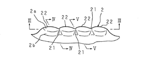
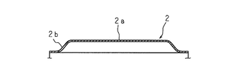
【解決手段】 相対回転を可能に嵌合される2つの部材間に配置され、軸長方向に設けられたスリット1及び複数の周方向位置に軸長方向と平行的に設けられた凸条2を有しており、この凸条2を、長手方向両端間に狭幅部21を有する構成とし、1つの凸条2の長手方向両端部、及び狭幅部21に押圧反力を発生させるようにした。
【選択図】 図1
Description
従って、自動車のステアリング装置に装着される車両盗難防止用のキ−ロック部など、比較的大きいスリップトルクを必要とする個所にスリップリングを使用する場合、充分なスリップトルクを得ることができず、改善策が要望されていた。スリップトルクを増加する手段として、例えばWO94/29609に記載されているように、軸長方向両側に複数の凸条を並設したスリップリングが知られている。しかしながら、この特許文献のスリップリングにあっては、筒体の全長が2倍程度に長くなり、筒体の全体が大型になると言う問題がある。
1 スリット
2 凸条
2b 周面(側面)
21 狭幅部
Claims (2)
- 相対回転を可能に嵌合される2つの部材間に配置され、その軸長方向に設けられたスリット及び複数の周方向位置に軸長方向と平行的に設けられた凸条を有する筒体において、前記凸条は狭幅部を有することを特徴とする筒体。
- 前記凸条は両側面の一部に設けられた凹所を前記狭幅部としてある請求項1記載の筒体。
Priority Applications (3)
| Application Number | Priority Date | Filing Date | Title |
|---|---|---|---|
| JP2004175747A JP2005351457A (ja) | 2004-06-14 | 2004-06-14 | 筒体 |
| DE200560010632 DE602005010632D1 (de) | 2004-06-14 | 2005-06-14 | Zylindrischer Körper |
| EP20050105202 EP1607290B1 (en) | 2004-06-14 | 2005-06-14 | Cylindrical body |
Applications Claiming Priority (1)
| Application Number | Priority Date | Filing Date | Title |
|---|---|---|---|
| JP2004175747A JP2005351457A (ja) | 2004-06-14 | 2004-06-14 | 筒体 |
Publications (2)
| Publication Number | Publication Date |
|---|---|
| JP2005351457A true JP2005351457A (ja) | 2005-12-22 |
| JP2005351457A5 JP2005351457A5 (ja) | 2007-07-26 |
Family
ID=34940161
Family Applications (1)
| Application Number | Title | Priority Date | Filing Date |
|---|---|---|---|
| JP2004175747A Pending JP2005351457A (ja) | 2004-06-14 | 2004-06-14 | 筒体 |
Country Status (3)
| Country | Link |
|---|---|
| EP (1) | EP1607290B1 (ja) |
| JP (1) | JP2005351457A (ja) |
| DE (1) | DE602005010632D1 (ja) |
Cited By (4)
| Publication number | Priority date | Publication date | Assignee | Title |
|---|---|---|---|---|
| WO2014080845A1 (ja) | 2012-11-26 | 2014-05-30 | 日本精工株式会社 | ステアリング装置 |
| WO2014080844A1 (ja) | 2012-11-26 | 2014-05-30 | 日本精工株式会社 | ステアリング装置 |
| JP2014156225A (ja) * | 2013-02-18 | 2014-08-28 | Aisin Seiki Co Ltd | 車両のステアリング装置 |
| JP2020032527A (ja) * | 2018-08-27 | 2020-03-05 | 卓也 澤田 | ホルダー部材 |
Families Citing this family (4)
| Publication number | Priority date | Publication date | Assignee | Title |
|---|---|---|---|---|
| DE102006036858A1 (de) * | 2006-08-07 | 2008-06-05 | GM Global Technology Operations, Inc., Detroit | Lenkspindelverriegelung für Fahrzeug |
| US7580225B2 (en) * | 2006-08-15 | 2009-08-25 | Intri-Plex Technologies, Inc. | Tolerance ring having variable height and/or assymmetrically located bumps |
| FR2929214B1 (fr) * | 2008-03-25 | 2010-03-26 | Renault Sas | Dispositif antivol pour arbre de direction de vehicule automobile |
| DE102008040877A1 (de) * | 2008-07-31 | 2010-02-04 | Zf Lenksysteme Gmbh | Vorrichtung zum Verriegeln einer Lenkung und damit ausgestattetes Lenksystem |
Citations (3)
| Publication number | Priority date | Publication date | Assignee | Title |
|---|---|---|---|---|
| US3838928A (en) * | 1972-03-06 | 1974-10-01 | Star Kugelhalter Gmbh Dt | Spacer ring |
| JPS5126575B1 (ja) * | 1970-04-16 | 1976-08-07 | ||
| WO1994029609A1 (en) * | 1993-06-16 | 1994-12-22 | Lilleshall Plastics And Engineering Ltd. | Tolerance rings |
Family Cites Families (6)
| Publication number | Priority date | Publication date | Assignee | Title |
|---|---|---|---|---|
| DE1855948U (de) * | 1959-12-14 | 1962-08-02 | Martin Hausner | Verdrehsicheres verbindungselement zur befestigung von maschinenteilen auf wellen. |
| BE624354A (ja) * | 1961-11-02 | 1900-01-01 | ||
| DE2361218C2 (de) * | 1973-12-08 | 1982-06-03 | Industriewerk Schaeffler Ohg, 8522 Herzogenaurach | Toleranzring aus Blech |
| DE3435084A1 (de) * | 1984-09-25 | 1986-04-03 | Daimler-Benz Ag, 7000 Stuttgart | Lenkschloss fuer kraftfahrzeuge |
| US4790683A (en) * | 1987-10-05 | 1988-12-13 | Cramer Jr Arthur A | Tolerance ring and shim and method of use |
| JPH03174266A (ja) | 1989-12-01 | 1991-07-29 | Nishikawa Kasei Kk | 被塗装体の保持装置 |
-
2004
- 2004-06-14 JP JP2004175747A patent/JP2005351457A/ja active Pending
-
2005
- 2005-06-14 EP EP20050105202 patent/EP1607290B1/en not_active Expired - Fee Related
- 2005-06-14 DE DE200560010632 patent/DE602005010632D1/de active Active
Patent Citations (3)
| Publication number | Priority date | Publication date | Assignee | Title |
|---|---|---|---|---|
| JPS5126575B1 (ja) * | 1970-04-16 | 1976-08-07 | ||
| US3838928A (en) * | 1972-03-06 | 1974-10-01 | Star Kugelhalter Gmbh Dt | Spacer ring |
| WO1994029609A1 (en) * | 1993-06-16 | 1994-12-22 | Lilleshall Plastics And Engineering Ltd. | Tolerance rings |
Cited By (8)
| Publication number | Priority date | Publication date | Assignee | Title |
|---|---|---|---|---|
| WO2014080845A1 (ja) | 2012-11-26 | 2014-05-30 | 日本精工株式会社 | ステアリング装置 |
| WO2014080844A1 (ja) | 2012-11-26 | 2014-05-30 | 日本精工株式会社 | ステアリング装置 |
| CN104797469A (zh) * | 2012-11-26 | 2015-07-22 | 日本精工株式会社 | 转向装置 |
| US9102292B2 (en) | 2012-11-26 | 2015-08-11 | Nsk Ltd. | Steering apparatus |
| US9266502B2 (en) | 2012-11-26 | 2016-02-23 | Nsk Ltd. | Steering apparatus |
| JP2016155550A (ja) * | 2012-11-26 | 2016-09-01 | 日本精工株式会社 | ステアリング装置 |
| JP2014156225A (ja) * | 2013-02-18 | 2014-08-28 | Aisin Seiki Co Ltd | 車両のステアリング装置 |
| JP2020032527A (ja) * | 2018-08-27 | 2020-03-05 | 卓也 澤田 | ホルダー部材 |
Also Published As
| Publication number | Publication date |
|---|---|
| EP1607290B1 (en) | 2008-10-29 |
| DE602005010632D1 (de) | 2008-12-11 |
| EP1607290A1 (en) | 2005-12-21 |
Similar Documents
| Publication | Publication Date | Title |
|---|---|---|
| EP1607290B1 (en) | Cylindrical body | |
| US10059366B2 (en) | Electrically driven power steering device | |
| JP6351007B2 (ja) | ステアリング装置 | |
| JP2007106402A (ja) | 操向装置のスリップジョイント | |
| JP2010095006A (ja) | 電動式パワーステアリング装置 | |
| JP2006249875A (ja) | 折りたたみ式収納具 | |
| JP2005351457A5 (ja) | ||
| JP2008174024A (ja) | 電動式パワーステアリング装置 | |
| JP5900646B2 (ja) | ステアリング装置 | |
| JP4051925B2 (ja) | ロック機構を具える車両用操舵装置 | |
| JP6187635B2 (ja) | ステアリング装置 | |
| JP2007203947A (ja) | 電動式パワーステアリング装置用ウォーム減速機及びこれを組み込んだ電動式パワーステアリング装置 | |
| JP2007229067A (ja) | シートのリクライニング装置およびその製造方法 | |
| JP4694384B2 (ja) | ステアリングロック装置 | |
| JP2006264424A (ja) | ステアリング装置 | |
| KR20140135328A (ko) | 자동차 조향축의 잠금장치 | |
| JP2009083657A (ja) | ステアリングロック装置 | |
| JP2005221033A (ja) | 固定式等速自在継手 | |
| JP2005162053A (ja) | ステアリングロック機構 | |
| JP4817007B2 (ja) | ステアリング装置 | |
| JP2007326438A (ja) | 自動変速機のパーキング構造 | |
| JPH09109903A (ja) | ステアリング機構 | |
| JP2006335165A (ja) | ステアリング装置 | |
| JP2014151821A (ja) | ステアリング装置 | |
| JP2008120277A (ja) | ステアリングシャフト |
Legal Events
| Date | Code | Title | Description |
|---|---|---|---|
| A521 | Written amendment |
Free format text: JAPANESE INTERMEDIATE CODE: A523 Effective date: 20070612 |
|
| A621 | Written request for application examination |
Free format text: JAPANESE INTERMEDIATE CODE: A621 Effective date: 20070612 |
|
| A977 | Report on retrieval |
Free format text: JAPANESE INTERMEDIATE CODE: A971007 Effective date: 20100301 |
|
| A131 | Notification of reasons for refusal |
Free format text: JAPANESE INTERMEDIATE CODE: A131 Effective date: 20100810 |
|
| A02 | Decision of refusal |
Free format text: JAPANESE INTERMEDIATE CODE: A02 Effective date: 20101207 |