JP2005299768A - センサ付軸受装置 - Google Patents
センサ付軸受装置 Download PDFInfo
- Publication number
- JP2005299768A JP2005299768A JP2004115347A JP2004115347A JP2005299768A JP 2005299768 A JP2005299768 A JP 2005299768A JP 2004115347 A JP2004115347 A JP 2004115347A JP 2004115347 A JP2004115347 A JP 2004115347A JP 2005299768 A JP2005299768 A JP 2005299768A
- Authority
- JP
- Japan
- Prior art keywords
- sensor
- plate
- mounting member
- sensor mounting
- elastic body
- Prior art date
- Legal status (The legal status is an assumption and is not a legal conclusion. Google has not performed a legal analysis and makes no representation as to the accuracy of the status listed.)
- Granted
Links
- 239000002184 metal Substances 0.000 claims description 6
- 238000005096 rolling process Methods 0.000 claims description 6
- 238000007789 sealing Methods 0.000 abstract description 13
- 230000008961 swelling Effects 0.000 abstract 1
- 230000002093 peripheral effect Effects 0.000 description 7
- XLYOFNOQVPJJNP-UHFFFAOYSA-N water Substances O XLYOFNOQVPJJNP-UHFFFAOYSA-N 0.000 description 7
- 230000000694 effects Effects 0.000 description 6
- 238000001514 detection method Methods 0.000 description 2
- 239000011347 resin Substances 0.000 description 2
- 229920005989 resin Polymers 0.000 description 2
- 239000004576 sand Substances 0.000 description 2
- 230000008878 coupling Effects 0.000 description 1
- 238000010168 coupling process Methods 0.000 description 1
- 238000005859 coupling reaction Methods 0.000 description 1
- 230000007423 decrease Effects 0.000 description 1
- 238000009434 installation Methods 0.000 description 1
- 238000004519 manufacturing process Methods 0.000 description 1
- 239000000463 material Substances 0.000 description 1
- 230000003287 optical effect Effects 0.000 description 1
- 239000002245 particle Substances 0.000 description 1
- 239000004033 plastic Substances 0.000 description 1
- 230000002265 prevention Effects 0.000 description 1
- 239000011435 rock Substances 0.000 description 1
- 239000000725 suspension Substances 0.000 description 1
- 238000004073 vulcanization Methods 0.000 description 1
Images
Classifications
-
- F—MECHANICAL ENGINEERING; LIGHTING; HEATING; WEAPONS; BLASTING
- F16—ENGINEERING ELEMENTS AND UNITS; GENERAL MEASURES FOR PRODUCING AND MAINTAINING EFFECTIVE FUNCTIONING OF MACHINES OR INSTALLATIONS; THERMAL INSULATION IN GENERAL
- F16C—SHAFTS; FLEXIBLE SHAFTS; ELEMENTS OR CRANKSHAFT MECHANISMS; ROTARY BODIES OTHER THAN GEARING ELEMENTS; BEARINGS
- F16C19/00—Bearings with rolling contact, for exclusively rotary movement
- F16C19/02—Bearings with rolling contact, for exclusively rotary movement with bearing balls essentially of the same size in one or more circular rows
- F16C19/14—Bearings with rolling contact, for exclusively rotary movement with bearing balls essentially of the same size in one or more circular rows for both radial and axial load
- F16C19/18—Bearings with rolling contact, for exclusively rotary movement with bearing balls essentially of the same size in one or more circular rows for both radial and axial load with two or more rows of balls
- F16C19/181—Bearings with rolling contact, for exclusively rotary movement with bearing balls essentially of the same size in one or more circular rows for both radial and axial load with two or more rows of balls with angular contact
- F16C19/183—Bearings with rolling contact, for exclusively rotary movement with bearing balls essentially of the same size in one or more circular rows for both radial and axial load with two or more rows of balls with angular contact with two rows at opposite angles
- F16C19/184—Bearings with rolling contact, for exclusively rotary movement with bearing balls essentially of the same size in one or more circular rows for both radial and axial load with two or more rows of balls with angular contact with two rows at opposite angles in O-arrangement
- F16C19/186—Bearings with rolling contact, for exclusively rotary movement with bearing balls essentially of the same size in one or more circular rows for both radial and axial load with two or more rows of balls with angular contact with two rows at opposite angles in O-arrangement with three raceways provided integrally on parts other than race rings, e.g. third generation hubs
-
- F—MECHANICAL ENGINEERING; LIGHTING; HEATING; WEAPONS; BLASTING
- F16—ENGINEERING ELEMENTS AND UNITS; GENERAL MEASURES FOR PRODUCING AND MAINTAINING EFFECTIVE FUNCTIONING OF MACHINES OR INSTALLATIONS; THERMAL INSULATION IN GENERAL
- F16C—SHAFTS; FLEXIBLE SHAFTS; ELEMENTS OR CRANKSHAFT MECHANISMS; ROTARY BODIES OTHER THAN GEARING ELEMENTS; BEARINGS
- F16C33/00—Parts of bearings; Special methods for making bearings or parts thereof
- F16C33/72—Sealings
- F16C33/76—Sealings of ball or roller bearings
- F16C33/78—Sealings of ball or roller bearings with a diaphragm, disc, or ring, with or without resilient members
- F16C33/7886—Sealings of ball or roller bearings with a diaphragm, disc, or ring, with or without resilient members mounted outside the gap between the inner and outer races, e.g. sealing rings mounted to an end face or outer surface of a race
-
- F—MECHANICAL ENGINEERING; LIGHTING; HEATING; WEAPONS; BLASTING
- F16—ENGINEERING ELEMENTS AND UNITS; GENERAL MEASURES FOR PRODUCING AND MAINTAINING EFFECTIVE FUNCTIONING OF MACHINES OR INSTALLATIONS; THERMAL INSULATION IN GENERAL
- F16C—SHAFTS; FLEXIBLE SHAFTS; ELEMENTS OR CRANKSHAFT MECHANISMS; ROTARY BODIES OTHER THAN GEARING ELEMENTS; BEARINGS
- F16C33/00—Parts of bearings; Special methods for making bearings or parts thereof
- F16C33/72—Sealings
- F16C33/76—Sealings of ball or roller bearings
- F16C33/78—Sealings of ball or roller bearings with a diaphragm, disc, or ring, with or without resilient members
- F16C33/7896—Sealings of ball or roller bearings with a diaphragm, disc, or ring, with or without resilient members with two or more discrete sealings arranged in series
-
- F—MECHANICAL ENGINEERING; LIGHTING; HEATING; WEAPONS; BLASTING
- F16—ENGINEERING ELEMENTS AND UNITS; GENERAL MEASURES FOR PRODUCING AND MAINTAINING EFFECTIVE FUNCTIONING OF MACHINES OR INSTALLATIONS; THERMAL INSULATION IN GENERAL
- F16C—SHAFTS; FLEXIBLE SHAFTS; ELEMENTS OR CRANKSHAFT MECHANISMS; ROTARY BODIES OTHER THAN GEARING ELEMENTS; BEARINGS
- F16C41/00—Other accessories, e.g. devices integrated in the bearing not relating to the bearing function as such
- F16C41/007—Encoders, e.g. parts with a plurality of alternating magnetic poles
-
- F—MECHANICAL ENGINEERING; LIGHTING; HEATING; WEAPONS; BLASTING
- F16—ENGINEERING ELEMENTS AND UNITS; GENERAL MEASURES FOR PRODUCING AND MAINTAINING EFFECTIVE FUNCTIONING OF MACHINES OR INSTALLATIONS; THERMAL INSULATION IN GENERAL
- F16C—SHAFTS; FLEXIBLE SHAFTS; ELEMENTS OR CRANKSHAFT MECHANISMS; ROTARY BODIES OTHER THAN GEARING ELEMENTS; BEARINGS
- F16C2326/00—Articles relating to transporting
- F16C2326/01—Parts of vehicles in general
- F16C2326/02—Wheel hubs or castors
Landscapes
- Engineering & Computer Science (AREA)
- General Engineering & Computer Science (AREA)
- Mechanical Engineering (AREA)
- Sealing Of Bearings (AREA)
- Rolling Contact Bearings (AREA)
Abstract
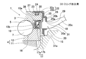
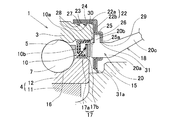
【解決手段】 軸受部1の内方部材4に回転センサ部2のエンコーダ17を取付け、外方部材3の端部にセンサ取付部材22を介してセンサ18を取付ける。センサ取付部材22は、外方部材3の外径面に嵌合する嵌合筒部22a、および外方部材3の端面に接して軸方向に位置決めされる側板部22bを有する。センサ取付部材22の前記側板部22aに、半径方向に沿う断面形状がコ字状の外方へ膨らむ凹み板部25を設ける。この凹み板部25と対向板部26との間に、センサ18を挟み込み状態に取付ける。センサ取付部材22は、内板23と外板24とが二重に重なったものとする。外方部材3の外径面とセンサ取付部材22の嵌合筒部22aとの間に、弾性体27を介在させる。
【選択図】 図2
Description
センサを取付ける構成例としては、板金プレス加工製のセンサ取付部材を用いたものが提案されている(例えば、特許文献1)。この提案例のものは、外輪に嵌合して取付けられる環状の支持体に切欠孔を設け、この切欠孔の両側縁にセンサの両側部を嵌合させる一対の滑り溝形成部を設け、上記切欠孔の下縁にセンサの背面を押し付ける舌片を設けたものである。
また、上記他の取付構成例は、センサ要素を埋め込んだセンサホルダと外輪嵌合筒とが一体にモールド成形されているため、車種、軸受容量等の異なるサイズのセンサ付軸受装置毎にそれぞれサイズの異なるセンサホルダを製作する必要があり、コスト高になる。
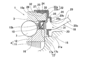
このセンサ取付部材は、前記外方部材の外径面に嵌合する嵌合筒部、および外方部材の端面に接して軸方向に位置決めされる側板部を有する。このセンサ取付部材の前記側板部に、内面側が凹む凹み板部とこの凹み板部の底面部分に対面する対向板部とを設け、これら凹み板部の底面部分と前記対向板部との間に前記センサを挟み込み状態に取付ける。前記凹み板部は、例えば軸受半径方向に沿う断面形状がコ字状のものとされる。また、前記外方部材の外径面とセンサ取付部材の前記嵌合筒部との間、および前記外方部材の端面とセンサ取付部材の前記側板部との間の少なくとも一方に弾性体を介在させる。
また、外方部材の外径面とセンサ取付部材の前記嵌合筒部との間、および前記外方部材の端面とセンサ取付部材の前記側板部との間の少なくとも一方に弾性体を介在させているので、シール性が向上し、外方部材とセンサ取付部材との間から、センサ取付部材で覆われる軸受内へ水などが浸入することの防止機能が高められる。
センサ取付部材が互いに重なる内板および外板からなるものであると、センサをセンサ取付部材の上記コ字状の凹み板部と対向板部との間に挟み込む作業が簡単に行える。
前記弾性体は、センサ取付部材の前記嵌合筒部に接着しておいても良く、これにより、センサ取付部材の固定がより一層確実となる。センサ取付部材が上記2枚の金属板製の内板および外板からなるものである場合は、内板の内面に弾性体を接着する。
弾性体としてOリングを用いると、優れたシール性が得易い。
外板の方が内板よりも延びていることにより、外板が内板に対して抜け難くなり、振動等で外板が内板から緩んだり外たりすることが防止される。また、両板の重なり面に水等が侵入することが防止される。
軸受部1は、内周に複列の軌道面5を形成した外方部材3と、上記各軌道面5に対向する軌道面6を形成した内方部材4と、これら外方部材3および内方部材4の軌道面5,6間に介在した複列の転動体7とで構成される。各列の転動体7は保持器8により保持されている。外方部材3と内方部材4との間の軸受空間の両端は、シール9,10によりそれぞれ密封されている。
内方部材4は、アウトボード側端に車輪取付用フランジ11aを有するハブ輪11と、このハブ輪11のインボード側端の外周に嵌合した内輪12とを有し、これらハブ輪11および内輪12に前記複列の軌道面6における各列の軌道面6が設けられている。なお、アウトボード側とは、車輪用軸受装置を車両に取付けた状態で車幅方向の外側となる側を言い、中央側となる側をインボード側と言う。
エンコーダ17は磁気エンコーダからなり、断面L字状の環状の芯金17aの側板部に多極磁石17bを設けたものとされている。エンコーダ17は、芯金17aの円筒部を内方部材4の外周に圧入することより、内方部材4に取付けられている。多極磁石17bは、円周方向に交互に磁極N,Sを形成した部材であり、ゴム磁石、プラスチック磁石、または焼結磁石などからなる。
弾性体27は、嵌合筒部22aにおいて、内板23の内面に加硫接着等により接着されたものとする。また、外方部材3の前記嵌合筒部22aが嵌合する外径面部分には、前記弾性体27を抜け止めする抜止溝28が設けられている。この抜止溝28に前記弾性体27が係合することで、センサ取付部材22の外方部材3からの抜け止めも確実となる。前記抜止溝28は、弾性体27の抜け止めをより確実にするために、軸受端部側に向けて下降傾斜する断面鋸歯状とされている。弾性体27は、その内周面に、抜止溝28に嵌まり込む突条が設けられたものであっても良く、また内周面が平坦面に形成されていて、圧入に伴って内周面が抜止溝28内に嵌まり込むように膨らむものであっても良い。
弾性体31は、センサ18の安定取付けとシール手段とに兼用されるため、部品点数を増やすことなくシール性を高めることができる。
この構成の場合は、弾性体31のリップ部31aの接触が等速ジョイントの結合状態に依存せず、この車輪用軸受装置の車体への取付作業が簡単である。この実施形態におけるその他の構成,効果は、第1の実施形態と同様である。
また、上記各実施形態は、車輪用軸受装置に適用した場合につき説明したが、この発明は回転センサ部を有するラジアル型の転がり軸受一般に適用することができる。
また、上記各実施形態において、エンコーダ17およびセンサ部18は磁気式のものとしたが、光学式のものであっても良い。
2…回転センサ部
3…外方部材
4…内方部材
7…転動体
17…エンコーダ
18…センサ
22…センサ取付部材
22a…嵌合筒部
22b…側板部
23…内板
24…外板
25…凹み板部
25a…底面部分
26…対向板部
27…弾性体
28…抜止溝
38…Oリング嵌合溝
31a…リップ部
Claims (6)
- 内周に軌道面を有する外方部材、上記軌道面に対向する軌道面を有する内方部材、および前記両軌道面の間に介在した転動体を有する軸受部と、前記内方部材の端部に取付けられたエンコーダ、およびこのエンコーダに対向して前記外方部材の端部に取付けられるセンサを有する回転センサ部とを備えたセンサ付軸受装置において、
前記外方部材の外径面に嵌合する嵌合筒部、および前記外方部材の端面に接して軸方向に位置決めされる側板部を有するセンサ取付部材を設け、このセンサ取付部材の前記側板部に、内面側が凹む凹み板部とこの凹み板部の底面部分に対面する対向板部とを設け、これら凹み板部の底面部分と前記対向板部との間に前記センサを挟み込み状態に取付け、前記外方部材の外径面と前記センサ取付部材の前記嵌合筒部との間、および前記外方部材の端面と前記センサ取付部材の側板部との間の少なくとも一方に弾性体を介在させたことを特徴とするセンサ付軸受装置。 - 請求項1において、前記センサ取付部材が、互いに内外に重なった2枚の金属板製の内板および外板からなり、前記外板に前記凹み板部を設け、前記内板に前記対向板部を設けたセンサ付軸受装置。
- 請求項1または請求項2において、前記外方部材の前記嵌合筒部が嵌合する外径面部分に、前記弾性体を抜け止めする抜止溝を設けたセンサ付軸受装置。
- 請求項3において、前記弾性体を前記センサ取付部材の前記嵌合筒部に接着したセンサ付軸受装置。
- 請求項1または請求項2において、前記外方部材の前記嵌合筒部が嵌合する外径面部分にOリング嵌合溝を設け、前記弾性体を、前記Oリング嵌合溝に嵌合したOリングとしたセンサ付軸受装置。
- 請求項2ないし請求項4のいずれか1項において、前記外方部材の前記嵌合筒部が嵌合する外径面部分に、前記弾性体を抜け止めする抜止溝を設け、前記センサ取付部材における内板および外板の前記嵌合筒部を構成する部分を、内板よりも外板の方が軸受中央側へ延びるものとしたセンサ付軸受装置。
Priority Applications (1)
| Application Number | Priority Date | Filing Date | Title |
|---|---|---|---|
| JP2004115347A JP4508704B2 (ja) | 2004-04-09 | 2004-04-09 | センサ付軸受装置 |
Applications Claiming Priority (1)
| Application Number | Priority Date | Filing Date | Title |
|---|---|---|---|
| JP2004115347A JP4508704B2 (ja) | 2004-04-09 | 2004-04-09 | センサ付軸受装置 |
Publications (2)
| Publication Number | Publication Date |
|---|---|
| JP2005299768A true JP2005299768A (ja) | 2005-10-27 |
| JP4508704B2 JP4508704B2 (ja) | 2010-07-21 |
Family
ID=35331547
Family Applications (1)
| Application Number | Title | Priority Date | Filing Date |
|---|---|---|---|
| JP2004115347A Expired - Fee Related JP4508704B2 (ja) | 2004-04-09 | 2004-04-09 | センサ付軸受装置 |
Country Status (1)
| Country | Link |
|---|---|
| JP (1) | JP4508704B2 (ja) |
Cited By (9)
| Publication number | Priority date | Publication date | Assignee | Title |
|---|---|---|---|---|
| WO2008136169A1 (ja) * | 2007-04-13 | 2008-11-13 | Ntn Corporation | 回転速度検出装置付き車輪用軸受装置 |
| WO2009011340A1 (ja) * | 2007-07-17 | 2009-01-22 | Nsk Ltd. | ハブユニット軸受 |
| JP2009097660A (ja) * | 2007-10-18 | 2009-05-07 | Jtekt Corp | センサ付き転がり軸受装置 |
| JP2009197941A (ja) * | 2008-02-22 | 2009-09-03 | Ntn Corp | 回転速度検出装置付き車輪用軸受装置 |
| JP2010180955A (ja) * | 2009-02-05 | 2010-08-19 | Jtekt Corp | 密封構造および軸受装置 |
| WO2011115252A1 (ja) * | 2010-03-18 | 2011-09-22 | Ntn株式会社 | 回転速度検出装置付き車輪用軸受装置 |
| JP2012036997A (ja) * | 2010-08-09 | 2012-02-23 | Nsk Ltd | エンコーダ付転がり軸受ユニット |
| US8123410B2 (en) | 2007-11-08 | 2012-02-28 | Jtekt Corporation | Rolling bearing device |
| EP2752308A1 (en) * | 2013-01-08 | 2014-07-09 | Aktiebolaget SKF | Rolling bearing unit with an encoder and protective cover for a vehicle wheel hub |
Citations (6)
| Publication number | Priority date | Publication date | Assignee | Title |
|---|---|---|---|---|
| JPS60143002U (ja) * | 1984-03-02 | 1985-09-21 | ダイハツ工業株式会社 | ホイ−ルベアリングのシ−ル構造 |
| JPH0527335U (ja) * | 1991-09-13 | 1993-04-09 | 日本精工株式会社 | センサ付転がり軸受ユニツト |
| JPH09236611A (ja) * | 1996-02-29 | 1997-09-09 | Nippon Seiko Kk | 回転速度検出装置付転がり軸受ユニットのセンサ取付部 |
| JP2002214245A (ja) * | 2001-01-16 | 2002-07-31 | Nsk Ltd | 回転速度検出装置付転がり軸受ユニット |
| JP2003262645A (ja) * | 2002-03-08 | 2003-09-19 | Ntn Corp | 回転検出装置およびこれを用いたアンチロックブレーキ装置 |
| JP2003262647A (ja) * | 2002-03-08 | 2003-09-19 | Ntn Corp | 回転検出装置およびこれを搭載した車輪用軸受装置 |
-
2004
- 2004-04-09 JP JP2004115347A patent/JP4508704B2/ja not_active Expired - Fee Related
Patent Citations (6)
| Publication number | Priority date | Publication date | Assignee | Title |
|---|---|---|---|---|
| JPS60143002U (ja) * | 1984-03-02 | 1985-09-21 | ダイハツ工業株式会社 | ホイ−ルベアリングのシ−ル構造 |
| JPH0527335U (ja) * | 1991-09-13 | 1993-04-09 | 日本精工株式会社 | センサ付転がり軸受ユニツト |
| JPH09236611A (ja) * | 1996-02-29 | 1997-09-09 | Nippon Seiko Kk | 回転速度検出装置付転がり軸受ユニットのセンサ取付部 |
| JP2002214245A (ja) * | 2001-01-16 | 2002-07-31 | Nsk Ltd | 回転速度検出装置付転がり軸受ユニット |
| JP2003262645A (ja) * | 2002-03-08 | 2003-09-19 | Ntn Corp | 回転検出装置およびこれを用いたアンチロックブレーキ装置 |
| JP2003262647A (ja) * | 2002-03-08 | 2003-09-19 | Ntn Corp | 回転検出装置およびこれを搭載した車輪用軸受装置 |
Cited By (15)
| Publication number | Priority date | Publication date | Assignee | Title |
|---|---|---|---|---|
| WO2008136169A1 (ja) * | 2007-04-13 | 2008-11-13 | Ntn Corporation | 回転速度検出装置付き車輪用軸受装置 |
| WO2009011340A1 (ja) * | 2007-07-17 | 2009-01-22 | Nsk Ltd. | ハブユニット軸受 |
| JP2009024732A (ja) * | 2007-07-17 | 2009-02-05 | Nsk Ltd | ハブユニット軸受 |
| US8419288B2 (en) | 2007-07-17 | 2013-04-16 | Nsk Ltd. | Hub unit bearing |
| JP2009097660A (ja) * | 2007-10-18 | 2009-05-07 | Jtekt Corp | センサ付き転がり軸受装置 |
| US8123410B2 (en) | 2007-11-08 | 2012-02-28 | Jtekt Corporation | Rolling bearing device |
| JP2009197941A (ja) * | 2008-02-22 | 2009-09-03 | Ntn Corp | 回転速度検出装置付き車輪用軸受装置 |
| JP2010180955A (ja) * | 2009-02-05 | 2010-08-19 | Jtekt Corp | 密封構造および軸受装置 |
| WO2011115252A1 (ja) * | 2010-03-18 | 2011-09-22 | Ntn株式会社 | 回転速度検出装置付き車輪用軸受装置 |
| JP2011196425A (ja) * | 2010-03-18 | 2011-10-06 | Ntn Corp | 回転速度検出装置付き車輪用軸受装置 |
| US8585298B2 (en) | 2010-03-18 | 2013-11-19 | Ntn Corporation | Wheel bearing apparatus incorporated with a rotation speed detecting apparatus |
| JP2012036997A (ja) * | 2010-08-09 | 2012-02-23 | Nsk Ltd | エンコーダ付転がり軸受ユニット |
| EP2752308A1 (en) * | 2013-01-08 | 2014-07-09 | Aktiebolaget SKF | Rolling bearing unit with an encoder and protective cover for a vehicle wheel hub |
| ITTO20130006A1 (it) * | 2013-01-08 | 2014-07-09 | Skf Ab | Gruppo cuscinetto per una ruota di un veicolo |
| US9016949B2 (en) | 2013-01-08 | 2015-04-28 | Aktiebolaget Skf | Bearing unit for a vehicle wheel |
Also Published As
| Publication number | Publication date |
|---|---|
| JP4508704B2 (ja) | 2010-07-21 |
Similar Documents
| Publication | Publication Date | Title |
|---|---|---|
| US5863124A (en) | Rolling bearing unit having tone wheel | |
| WO2005078457A1 (ja) | センサ付軸受装置 | |
| US20110089642A1 (en) | Bearing Seal | |
| JP2009115257A (ja) | 転がり軸受装置 | |
| JP4508704B2 (ja) | センサ付軸受装置 | |
| US20040046328A1 (en) | Seal with integrated sealing and rotation measuring capabilities | |
| JP2005265826A (ja) | センサ付軸受装置 | |
| JP2004011827A (ja) | 車輪用軸受の磁気エンコーダ付きシールド構造 | |
| JP2005331429A (ja) | エンコーダ付転がり軸受装置 | |
| JPH11174068A (ja) | エンコーダ付転がり軸受ユニット | |
| JP5067718B2 (ja) | センサー付き転がり軸受装置 | |
| JP2004211832A (ja) | センサ対応軸受装置 | |
| JP5098730B2 (ja) | 自動二輪車の車輪用回転速度検出装置 | |
| JP2007120560A (ja) | 車輪用軸受装置 | |
| EP1780549B1 (en) | Seal device with sensor and rolling bearing device using the same | |
| JP5035754B2 (ja) | センサー付き転がり軸受装置 | |
| JP4026557B2 (ja) | 回転検出用のパルサリングおよびシール装置 | |
| JP2010048290A (ja) | 磁気エンコーダ付き密封装置 | |
| JP5196180B2 (ja) | センサ付き転がり軸受装置 | |
| JP2004190736A (ja) | 車輪用軸受装置 | |
| JP4656917B2 (ja) | 回転速度検出装置付車輪用軸受装置 | |
| JP2008267423A (ja) | ベアリングシール | |
| JP2008215921A (ja) | 着磁パルサリング、及びこれを用いたセンサ付き転がり軸受装置 | |
| JP2006064145A (ja) | 車輪用軸受装置 | |
| JP4023405B2 (ja) | 回転検出用のパルサリング、シール装置および転がり軸受装置 |
Legal Events
| Date | Code | Title | Description |
|---|---|---|---|
| A621 | Written request for application examination |
Free format text: JAPANESE INTERMEDIATE CODE: A621 Effective date: 20070404 |
|
| A977 | Report on retrieval |
Free format text: JAPANESE INTERMEDIATE CODE: A971007 Effective date: 20090827 |
|
| A131 | Notification of reasons for refusal |
Free format text: JAPANESE INTERMEDIATE CODE: A131 Effective date: 20090915 |
|
| A521 | Written amendment |
Free format text: JAPANESE INTERMEDIATE CODE: A523 Effective date: 20091112 |
|
| TRDD | Decision of grant or rejection written | ||
| A01 | Written decision to grant a patent or to grant a registration (utility model) |
Free format text: JAPANESE INTERMEDIATE CODE: A01 Effective date: 20100427 |
|
| A01 | Written decision to grant a patent or to grant a registration (utility model) |
Free format text: JAPANESE INTERMEDIATE CODE: A01 |
|
| A61 | First payment of annual fees (during grant procedure) |
Free format text: JAPANESE INTERMEDIATE CODE: A61 Effective date: 20100427 |
|
| FPAY | Renewal fee payment (event date is renewal date of database) |
Free format text: PAYMENT UNTIL: 20130514 Year of fee payment: 3 |
|
| R150 | Certificate of patent or registration of utility model |
Free format text: JAPANESE INTERMEDIATE CODE: R150 |
|
| LAPS | Cancellation because of no payment of annual fees |


