JP2005299768A - Bearing device with sensor - Google Patents
Bearing device with sensor Download PDFInfo
- Publication number
- JP2005299768A JP2005299768A JP2004115347A JP2004115347A JP2005299768A JP 2005299768 A JP2005299768 A JP 2005299768A JP 2004115347 A JP2004115347 A JP 2004115347A JP 2004115347 A JP2004115347 A JP 2004115347A JP 2005299768 A JP2005299768 A JP 2005299768A
- Authority
- JP
- Japan
- Prior art keywords
- sensor
- plate
- mounting member
- sensor mounting
- elastic body
- Prior art date
- Legal status (The legal status is an assumption and is not a legal conclusion. Google has not performed a legal analysis and makes no representation as to the accuracy of the status listed.)
- Granted
Links
- 239000002184 metal Substances 0.000 claims description 6
- 238000005096 rolling process Methods 0.000 claims description 6
- 238000007789 sealing Methods 0.000 abstract description 13
- 230000008961 swelling Effects 0.000 abstract 1
- 230000002093 peripheral effect Effects 0.000 description 7
- XLYOFNOQVPJJNP-UHFFFAOYSA-N water Substances O XLYOFNOQVPJJNP-UHFFFAOYSA-N 0.000 description 7
- 230000000694 effects Effects 0.000 description 6
- 238000001514 detection method Methods 0.000 description 2
- 239000011347 resin Substances 0.000 description 2
- 229920005989 resin Polymers 0.000 description 2
- 239000004576 sand Substances 0.000 description 2
- 230000008878 coupling Effects 0.000 description 1
- 238000010168 coupling process Methods 0.000 description 1
- 238000005859 coupling reaction Methods 0.000 description 1
- 230000007423 decrease Effects 0.000 description 1
- 238000009434 installation Methods 0.000 description 1
- 238000004519 manufacturing process Methods 0.000 description 1
- 239000000463 material Substances 0.000 description 1
- 230000003287 optical effect Effects 0.000 description 1
- 239000002245 particle Substances 0.000 description 1
- 239000004033 plastic Substances 0.000 description 1
- 230000002265 prevention Effects 0.000 description 1
- 239000011435 rock Substances 0.000 description 1
- 239000000725 suspension Substances 0.000 description 1
- 238000004073 vulcanization Methods 0.000 description 1
Images


Classifications
-
- F—MECHANICAL ENGINEERING; LIGHTING; HEATING; WEAPONS; BLASTING
- F16—ENGINEERING ELEMENTS AND UNITS; GENERAL MEASURES FOR PRODUCING AND MAINTAINING EFFECTIVE FUNCTIONING OF MACHINES OR INSTALLATIONS; THERMAL INSULATION IN GENERAL
- F16C—SHAFTS; FLEXIBLE SHAFTS; ELEMENTS OR CRANKSHAFT MECHANISMS; ROTARY BODIES OTHER THAN GEARING ELEMENTS; BEARINGS
- F16C19/00—Bearings with rolling contact, for exclusively rotary movement
- F16C19/02—Bearings with rolling contact, for exclusively rotary movement with bearing balls essentially of the same size in one or more circular rows
- F16C19/14—Bearings with rolling contact, for exclusively rotary movement with bearing balls essentially of the same size in one or more circular rows for both radial and axial load
- F16C19/18—Bearings with rolling contact, for exclusively rotary movement with bearing balls essentially of the same size in one or more circular rows for both radial and axial load with two or more rows of balls
- F16C19/181—Bearings with rolling contact, for exclusively rotary movement with bearing balls essentially of the same size in one or more circular rows for both radial and axial load with two or more rows of balls with angular contact
- F16C19/183—Bearings with rolling contact, for exclusively rotary movement with bearing balls essentially of the same size in one or more circular rows for both radial and axial load with two or more rows of balls with angular contact with two rows at opposite angles
- F16C19/184—Bearings with rolling contact, for exclusively rotary movement with bearing balls essentially of the same size in one or more circular rows for both radial and axial load with two or more rows of balls with angular contact with two rows at opposite angles in O-arrangement
- F16C19/186—Bearings with rolling contact, for exclusively rotary movement with bearing balls essentially of the same size in one or more circular rows for both radial and axial load with two or more rows of balls with angular contact with two rows at opposite angles in O-arrangement with three raceways provided integrally on parts other than race rings, e.g. third generation hubs
-
- F—MECHANICAL ENGINEERING; LIGHTING; HEATING; WEAPONS; BLASTING
- F16—ENGINEERING ELEMENTS AND UNITS; GENERAL MEASURES FOR PRODUCING AND MAINTAINING EFFECTIVE FUNCTIONING OF MACHINES OR INSTALLATIONS; THERMAL INSULATION IN GENERAL
- F16C—SHAFTS; FLEXIBLE SHAFTS; ELEMENTS OR CRANKSHAFT MECHANISMS; ROTARY BODIES OTHER THAN GEARING ELEMENTS; BEARINGS
- F16C33/00—Parts of bearings; Special methods for making bearings or parts thereof
- F16C33/72—Sealings
- F16C33/76—Sealings of ball or roller bearings
- F16C33/78—Sealings of ball or roller bearings with a diaphragm, disc, or ring, with or without resilient members
- F16C33/7886—Sealings of ball or roller bearings with a diaphragm, disc, or ring, with or without resilient members mounted outside the gap between the inner and outer races, e.g. sealing rings mounted to an end face or outer surface of a race
-
- F—MECHANICAL ENGINEERING; LIGHTING; HEATING; WEAPONS; BLASTING
- F16—ENGINEERING ELEMENTS AND UNITS; GENERAL MEASURES FOR PRODUCING AND MAINTAINING EFFECTIVE FUNCTIONING OF MACHINES OR INSTALLATIONS; THERMAL INSULATION IN GENERAL
- F16C—SHAFTS; FLEXIBLE SHAFTS; ELEMENTS OR CRANKSHAFT MECHANISMS; ROTARY BODIES OTHER THAN GEARING ELEMENTS; BEARINGS
- F16C33/00—Parts of bearings; Special methods for making bearings or parts thereof
- F16C33/72—Sealings
- F16C33/76—Sealings of ball or roller bearings
- F16C33/78—Sealings of ball or roller bearings with a diaphragm, disc, or ring, with or without resilient members
- F16C33/7896—Sealings of ball or roller bearings with a diaphragm, disc, or ring, with or without resilient members with two or more discrete sealings arranged in series
-
- F—MECHANICAL ENGINEERING; LIGHTING; HEATING; WEAPONS; BLASTING
- F16—ENGINEERING ELEMENTS AND UNITS; GENERAL MEASURES FOR PRODUCING AND MAINTAINING EFFECTIVE FUNCTIONING OF MACHINES OR INSTALLATIONS; THERMAL INSULATION IN GENERAL
- F16C—SHAFTS; FLEXIBLE SHAFTS; ELEMENTS OR CRANKSHAFT MECHANISMS; ROTARY BODIES OTHER THAN GEARING ELEMENTS; BEARINGS
- F16C41/00—Other accessories, e.g. devices integrated in the bearing not relating to the bearing function as such
- F16C41/007—Encoders, e.g. parts with a plurality of alternating magnetic poles
-
- F—MECHANICAL ENGINEERING; LIGHTING; HEATING; WEAPONS; BLASTING
- F16—ENGINEERING ELEMENTS AND UNITS; GENERAL MEASURES FOR PRODUCING AND MAINTAINING EFFECTIVE FUNCTIONING OF MACHINES OR INSTALLATIONS; THERMAL INSULATION IN GENERAL
- F16C—SHAFTS; FLEXIBLE SHAFTS; ELEMENTS OR CRANKSHAFT MECHANISMS; ROTARY BODIES OTHER THAN GEARING ELEMENTS; BEARINGS
- F16C2326/00—Articles relating to transporting
- F16C2326/01—Parts of vehicles in general
- F16C2326/02—Wheel hubs or castors
Landscapes
- Engineering & Computer Science (AREA)
- General Engineering & Computer Science (AREA)
- Mechanical Engineering (AREA)
- Rolling Contact Bearings (AREA)
- Sealing Of Bearings (AREA)
Abstract
Description
この発明は、自動車における回転センサ付きの車輪用軸受や、その他各種の用途のセンサ付軸受装置に関する。 The present invention relates to a wheel bearing with a rotation sensor in an automobile and a sensor-equipped bearing device for various other purposes.
自動車の車輪用軸受装置では、アンチロックブレーキ装置の制御や、その他種々の目的で、車輪回転速度を検出する回転センサが設けられる。この回転センサは、回転側の軌道輪となる内輪に取付けられるリング状の磁気エンコーダと、静止側の軌道輪となる外輪に取付けられて上記磁気エンコーダを非接触で検出するセンサとで構成される。
センサを取付ける構成例としては、板金プレス加工製のセンサ取付部材を用いたものが提案されている(例えば、特許文献1)。この提案例のものは、外輪に嵌合して取付けられる環状の支持体に切欠孔を設け、この切欠孔の両側縁にセンサの両側部を嵌合させる一対の滑り溝形成部を設け、上記切欠孔の下縁にセンサの背面を押し付ける舌片を設けたものである。
BACKGROUND ART A wheel bearing device for an automobile is provided with a rotation sensor that detects a wheel rotation speed for control of an antilock brake device and various other purposes. This rotation sensor is composed of a ring-shaped magnetic encoder attached to an inner ring serving as a rotating raceway ring, and a sensor attached to an outer ring serving as a stationary raceway ring to detect the magnetic encoder in a non-contact manner. .
As a configuration example for mounting the sensor, a sensor mounting member made by sheet metal press working has been proposed (for example, Patent Document 1). In this proposed example, a notch hole is provided in an annular support that is fitted and attached to the outer ring, and a pair of sliding groove forming parts for fitting both sides of the sensor is provided on both side edges of the notch, A tongue piece for pressing the back surface of the sensor is provided at the lower edge of the notch hole.
センサを取付ける他の構成例としては、外輪に嵌合させる外輪嵌合筒に、円環状のセンサホルダを一体にモールド成形し、このセンサホルダの一部に設けた円弧状の保持部内にセンサ要素を埋め込んだものがある(例えば、特許文献2)。
上記の滑り溝形成部の間にセンサを差し込んで舌片で押しつける取付構造は、簡単に装着できるという利点があるが、不測に外れる恐れがある。また、車輪用軸受装置は路面に曝される環境下にあるため、土砂がセンサと磁気エンコーダとの間に入り易く、損傷の恐れがある。
また、上記他の取付構成例は、センサ要素を埋め込んだセンサホルダと外輪嵌合筒とが一体にモールド成形されているため、車種、軸受容量等の異なるサイズのセンサ付軸受装置毎にそれぞれサイズの異なるセンサホルダを製作する必要があり、コスト高になる。
The mounting structure in which the sensor is inserted between the sliding groove forming portions and pressed with the tongue piece has an advantage that it can be easily mounted, but there is a possibility that it may come off unexpectedly. Further, since the wheel bearing device is in an environment where it is exposed to the road surface, earth and sand are likely to enter between the sensor and the magnetic encoder, which may cause damage.
In the above other mounting configuration examples, since the sensor holder in which the sensor element is embedded and the outer ring fitting cylinder are integrally molded, each size is different for each sensor-equipped bearing device having different sizes such as vehicle type and bearing capacity. It is necessary to manufacture different sensor holders, which increases the cost.
これらの課題を解消するものとして、本出願人は、外方部材の外径面に嵌合する嵌合筒部、および外方部材の端面に接して軸方向に位置決めされる側板部を有するセンサ取付部材を設け、その側板部に凹み板部および対向板部を設けてセンサを挟み込み状態に取付けるものを提案した(特願2004−39201号)。しかし、嵌合筒部のシール性に関して、圧入だけでは今一つシール性の確保が難しいと考えられる。 In order to solve these problems, the applicant of the present invention has a sensor including a fitting tube portion that is fitted to the outer diameter surface of the outer member, and a side plate portion that is axially positioned in contact with the end surface of the outer member. An attachment member is provided, and a side plate portion is provided with a concave plate portion and a counter plate portion, and the sensor is attached in a sandwiched state (Japanese Patent Application No. 2004-39201). However, regarding the sealing property of the fitting cylinder part, it is considered that it is difficult to secure the sealing property by press-fitting alone.
この発明の目的は、センサの取付けが確実で、信頼性に優れ、種々異なるサイズの軸受部への対応が容易で、かつシール性にも優れて、低コストにできるセンサ付軸受装置を提供することである。 It is an object of the present invention to provide a sensor-equipped bearing device that can be attached to a sensor with high reliability, is highly reliable, easily accommodates bearings of various sizes, has excellent sealing properties, and can be manufactured at low cost. That is.
この発明のセンサ付軸受装置は、内周に軌道面を有する外方部材、上記軌道面に対向する軌道面を有する内方部材、および両軌道面の間に介在した転動体を有する軸受部と、前記内方部材の端部に取付けられるエンコーダ、およびこのエンコーダに対向して前記外方部材の端部に取付けられるセンサを有する回転センサ部とを備えたセンサ付軸受装置において、次のセンサ取付部材によりセンサを取付けたものである。
このセンサ取付部材は、前記外方部材の外径面に嵌合する嵌合筒部、および外方部材の端面に接して軸方向に位置決めされる側板部を有する。このセンサ取付部材の前記側板部に、内面側が凹む凹み板部とこの凹み板部の底面部分に対面する対向板部とを設け、これら凹み板部の底面部分と前記対向板部との間に前記センサを挟み込み状態に取付ける。前記凹み板部は、例えば軸受半径方向に沿う断面形状がコ字状のものとされる。また、前記外方部材の外径面とセンサ取付部材の前記嵌合筒部との間、および前記外方部材の端面とセンサ取付部材の前記側板部との間の少なくとも一方に弾性体を介在させる。
A bearing device with a sensor according to the present invention includes an outer member having a raceway surface on an inner periphery, an inner member having a raceway surface facing the raceway surface, and a bearing portion having a rolling element interposed between both raceway surfaces; A sensor-equipped bearing device comprising: an encoder attached to an end portion of the inner member; and a rotation sensor portion having a sensor attached to the end portion of the outer member so as to face the encoder. A sensor is attached by a member.
The sensor mounting member includes a fitting tube portion that is fitted to the outer diameter surface of the outer member, and a side plate portion that is axially positioned in contact with the end surface of the outer member. The side plate portion of the sensor mounting member is provided with a concave plate portion whose inner surface side is recessed and a counter plate portion facing the bottom surface portion of the concave plate portion, and between the bottom surface portion of the concave plate portion and the counter plate portion. The sensor is attached in a sandwiched state. The concave plate portion has, for example, a U-shaped cross section along the bearing radial direction. Further, an elastic body is interposed between the outer diameter surface of the outer member and the fitting tube portion of the sensor mounting member and between at least one of the end surface of the outer member and the side plate portion of the sensor mounting member. Let
この構成によると、センサ取付部材に設けられた凹み板部の底面部分と対向板部との間に前記センサを挟み込み状態に取付けたため、センサが外れる恐れがなく、取付けが確実で、信頼性の高いものとできる。センサ取付部材は、嵌合筒部で外方部材の外径面に嵌合し、側板部で外方部材の端面に接して軸方向に位置決めされるため、位置決めが簡単に精度良く行え、センサのエンコーダに対する位置決め精度が優れたものとできる。上記センサは、例えば、センサ素子を樹脂製等のセンサホルダ内に埋込んだものとされるが、このセンサホルダは、センサ取付部材とは別体に製作されてセンサ取付部材に取付けられる。そのため、種々異なるサイズの軸受部に取付ける場合に、センサ取付部材を軸受部のサイズに合わせたものとすることで対処できて、センサホルダ付きのセンサは同一のものを用いて種々異なるサイズの軸受部に対応できる。しがって、センサおよびセンサ取付部材からなるセンサユニットを低コストで製作できる。
また、外方部材の外径面とセンサ取付部材の前記嵌合筒部との間、および前記外方部材の端面とセンサ取付部材の前記側板部との間の少なくとも一方に弾性体を介在させているので、シール性が向上し、外方部材とセンサ取付部材との間から、センサ取付部材で覆われる軸受内へ水などが浸入することの防止機能が高められる。
According to this configuration, since the sensor is mounted in a state of being sandwiched between the bottom surface portion of the recessed plate portion provided on the sensor mounting member and the opposing plate portion, the sensor is not likely to come off, and the mounting is reliable and reliable. It can be expensive. The sensor mounting member is fitted to the outer diameter surface of the outer member at the fitting tube portion, and is positioned in the axial direction by contacting the end surface of the outer member at the side plate portion. The positioning accuracy for the encoder can be excellent. The sensor is, for example, a sensor element embedded in a sensor holder made of resin or the like. The sensor holder is manufactured separately from the sensor mounting member and is attached to the sensor mounting member. Therefore, when mounting on bearing parts of different sizes, it can be dealt with by adjusting the sensor mounting member to the size of the bearing section. It can correspond to the part. Therefore, a sensor unit including the sensor and the sensor mounting member can be manufactured at low cost.
Further, an elastic body is interposed between the outer diameter surface of the outer member and the fitting tube portion of the sensor mounting member and between at least one of the end surface of the outer member and the side plate portion of the sensor mounting member. Therefore, the sealing performance is improved, and the function of preventing water and the like from entering the bearing covered with the sensor mounting member from between the outer member and the sensor mounting member is enhanced.
前記センサ取付部材は、例えば、互いに内外に重なった2枚の金属板製の内板および外板からなるものとされる。その場合、前記外板に前記凹み板部を設け、前記内板に前記対向板部を設ける。
センサ取付部材が互いに重なる内板および外板からなるものであると、センサをセンサ取付部材の上記コ字状の凹み板部と対向板部との間に挟み込む作業が簡単に行える。
The sensor mounting member is made of, for example, two inner plates and an outer plate made of metal plates that overlap each other. In that case, the said recessed board part is provided in the said outer plate, and the said opposing board part is provided in the said inner board.
If the sensor mounting member is composed of an inner plate and an outer plate that overlap each other, the operation of sandwiching the sensor between the U-shaped recessed plate portion and the opposing plate portion of the sensor mounting member can be easily performed.
前記外方部材の前記嵌合筒部が嵌合する外径面部分には、前記弾性体を抜け止めする抜止溝を設けても良い。抜止溝を設けることで、弾性体が外方部材から抜け難くなり、外方部材へのセンサ取付部材の嵌合がより確実なものになる。
前記弾性体は、センサ取付部材の前記嵌合筒部に接着しておいても良く、これにより、センサ取付部材の固定がより一層確実となる。センサ取付部材が上記2枚の金属板製の内板および外板からなるものである場合は、内板の内面に弾性体を接着する。
A retaining groove for preventing the elastic body from coming off may be provided in an outer diameter surface portion into which the fitting cylindrical portion of the outer member is fitted. Providing the retaining groove makes it difficult for the elastic body to come out of the outer member, and the sensor mounting member can be more reliably fitted to the outer member.
The elastic body may be adhered to the fitting tube portion of the sensor mounting member, thereby further ensuring the fixing of the sensor mounting member. In the case where the sensor mounting member is composed of the two metal plate inner and outer plates, an elastic body is bonded to the inner surface of the inner plate.
前記外方部材の前記嵌合筒部が嵌合する外径面部分には、Oリング嵌合溝を設け、前記弾性体を、前記Oリング嵌合溝に嵌合したOリングとしても良い。
弾性体としてOリングを用いると、優れたシール性が得易い。
An O-ring fitting groove may be provided on an outer diameter surface portion of the outer member to which the fitting cylinder portion is fitted, and the elastic body may be an O-ring fitted in the O-ring fitting groove.
When an O-ring is used as the elastic body, excellent sealing properties can be easily obtained.
前記外方部材の前記嵌合筒部が嵌合する外径面部分には、前記弾性体を抜け止めする抜止溝を設け、前記センサ取付部材における内板および外板の前記嵌合筒部を構成する部分を、内板よりも外板の方が軸受中央側へ延びるものとしても良い。
外板の方が内板よりも延びていることにより、外板が内板に対して抜け難くなり、振動等で外板が内板から緩んだり外たりすることが防止される。また、両板の重なり面に水等が侵入することが防止される。
The outer diameter surface portion of the outer member to which the fitting tube portion is fitted is provided with a retaining groove for preventing the elastic body from being removed, and the fitting tube portion of the inner plate and the outer plate in the sensor mounting member is provided. It is good also considering the part to comprise as the outer plate extends toward the bearing center side rather than the inner plate.
Since the outer plate extends more than the inner plate, it is difficult for the outer plate to come out of the inner plate, and the outer plate is prevented from being loosened or detached from the inner plate due to vibration or the like. Further, water or the like is prevented from entering the overlapping surface of both plates.
この発明のセンサ付軸受装置は、外方部材の外径面に嵌合する嵌合筒部、および前記外方部材の端面に接して軸方向に位置決めされる側板部を有するセンサ取付部材を設け、このセンサ取付部材の前記側板部に、内面側が凹む凹み板部とこの凹み板部の底面部分に対面する対向板部とを設け、これら凹み板部の底面部分と前記対向板部との間に前記センサを挟み込み状態に取付け、前記外方部材の外径面と前記センサ取付部材の前記嵌合筒部との間、および前記外方部材の端面と前記センサ取付部材の側板部との間の少なくとも一方に弾性体を介在させたため、センサの取付けが確実で、信頼性に優れ、種々異なるサイズの軸受部への対応が容易で、かつシール性にも優れて、低コストにできるという効果が得られる。 A bearing device with a sensor according to the present invention is provided with a sensor mounting member having a fitting tube portion that fits on an outer diameter surface of an outer member, and a side plate portion that is in contact with an end surface of the outer member and is axially positioned. The side plate portion of the sensor mounting member is provided with a concave plate portion whose inner surface is recessed and a counter plate portion facing the bottom surface portion of the concave plate portion, and between the bottom surface portion of the concave plate portion and the counter plate portion. The sensor is sandwiched between the outer diameter surface of the outer member and the fitting tube portion of the sensor mounting member, and between the end surface of the outer member and the side plate portion of the sensor mounting member. Since the elastic body is interposed in at least one of the above, the sensor can be mounted reliably, excellent in reliability, easily compatible with bearing parts of various sizes, excellent in sealing properties, and low cost. Is obtained.
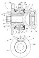
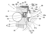
この発明の第1の実施形態を図1および図2と共に説明する。この実施形態は、第3世代型の車輪用軸受装置に適用したものである。このセンサ付軸受装置は、軸受部1に回転センサ部2を取付けたものであり、図1(A)は等速ジョイント14を連結した状態を示している。
軸受部1は、内周に複列の軌道面5を形成した外方部材3と、上記各軌道面5に対向する軌道面6を形成した内方部材4と、これら外方部材3および内方部材4の軌道面5,6間に介在した複列の転動体7とで構成される。各列の転動体7は保持器8により保持されている。外方部材3と内方部材4との間の軸受空間の両端は、シール9,10によりそれぞれ密封されている。
A first embodiment of the present invention will be described with reference to FIGS. This embodiment is applied to a third-generation type wheel bearing device. This bearing device with a sensor is obtained by attaching a
The
外方部材3は、一体の部品からなり、車体の懸架装置(図示せず)におけるナックル等に取付けるフランジ3aが外周に設けられている。
内方部材4は、アウトボード側端に車輪取付用フランジ11aを有するハブ輪11と、このハブ輪11のインボード側端の外周に嵌合した内輪12とを有し、これらハブ輪11および内輪12に前記複列の軌道面6における各列の軌道面6が設けられている。なお、アウトボード側とは、車輪用軸受装置を車両に取付けた状態で車幅方向の外側となる側を言い、中央側となる側をインボード側と言う。
The
The
内方部材4は、中央孔13を有し、等速ジョイント14の片方の継手部材となる外輪15のステム部15aが挿通される。ステム部15aは先端に雄ねじ部を有し、この雄ねじ部に螺合するナット16の締め付けにより、等速ジョイント外輪15が内方部材4に結合される。このとき、等速ジョイント外輪15に設けられた段面15bが、内方部材4の内輪12の幅面を押し付けることで、内輪12のハブ輪11に対する固定が行われる。
The
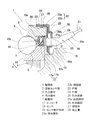
図2に拡大して示すように、回転センサ部2は、内方部材4の端部外周に取付けられるエンコーダ17、およびこのエンコーダ17に対向して外方部材3の端部に取付けられるセンサ18を有する。
エンコーダ17は磁気エンコーダからなり、断面L字状の環状の芯金17aの側板部に多極磁石17bを設けたものとされている。エンコーダ17は、芯金17aの円筒部を内方部材4の外周に圧入することより、内方部材4に取付けられている。多極磁石17bは、円周方向に交互に磁極N,Sを形成した部材であり、ゴム磁石、プラスチック磁石、または焼結磁石などからなる。
As shown in an enlarged view in FIG. 2, the
The
エンコーダ17は、この実施形態では、インボード側のシール10の構成部品を兼ねており、スリンガとしての機能を発揮する。このシール10は、エンコーダ17の芯金17aと、外方部材3の内径面に嵌合したシール部材10aとで構成される。シール部材10aは、環状の芯金にゴム等の弾性体を設けたものであり、エンコーダ17の芯金17aの側板部および円筒部にそれぞれ先端が摺接する複数のリップ部10bが、前記弾性体に設けられている。
In this embodiment, the
センサ18は、エンコーダ17の磁界を検出する磁気センサであり、センサ取付部材22を介して外方部材3に取付けられる。センサ18は、ホール素子や磁気抵抗素子等のセンサ素子19を、樹脂製等のセンサホルダ20内に埋め込んだものである。センサ18において、前記センサ素子19は、例えばエンコーダ17の磁極配列に対して、電気的位相が90°ずれた2つのパルス出力が得られるように、円周方向に離して2個設けられている。このため、センサ18のセンサホルダ20の本体部20aは、軸受中心と同心の円弧状に延びる正面形状とされている。センサホルダ20は、本体部20aの先端付近から外径側へ延びる張出部分20bを有し、かつ本体部20aから次第に小径となって検出面に対して後方へ延びるコードカバー部20cが設けられている。コードカバー部20cの先端から、コード21が延びている。張出部分20bは、本体部20aの軸受円周方向幅の全体から外径側へ張り出すものとされている。
The
センサ取付部材22は、外方部材3の外径面に嵌合する嵌合筒部22a、および外方部材3の端面に接して軸方向に位置決めされる側板部22bを有する。この側板部22bに、内面側が凹むカップ状の凹み板部25とこの凹み板部25の底面部分25aに対面する対向板部26とが設けられ、これら凹み板部25の底面部分25aと対向板部26との間に、センサ18が挟み込み状態に取付けられている。凹み板部25は、その軸受半径方向に沿う断面形状がコ字状とされる。凹み板部25は、詳しくはその正面形状が、図1(B)に示すようにセンサ取付部材22の円周方向に延びる円弧状とされ、その円弧状となった外周側辺と内周側辺の両端が、円弧状辺で続く形状とされている。
The
センサ取付部材22は、互いに内外に重なった2枚の金属板製の内板23および外板24からなり、前記外板24に前記凹み板部25が設けられ、内板23の一部が前記対向板部26となる。対向板部26は、図示の例では、内板23の側板部分における外板24の凹み板部25の底面部分25aと対向する部分からなる。内板23および外板24は、いずれも板金のプレス加工品からなる。
The
センサ取付部材22の外方部材3への取付けは、センサ取付部材22の嵌合筒部22aを、その嵌合筒部22aと外方部材3の外径面との間に弾性体27を介在させて外方部材3の外径面に圧入することで行われる。これにより、センサ取付部材22の嵌合筒部22aと外方部材22aの外径面との間が確実にシールされる。
弾性体27は、嵌合筒部22aにおいて、内板23の内面に加硫接着等により接着されたものとする。また、外方部材3の前記嵌合筒部22aが嵌合する外径面部分には、前記弾性体27を抜け止めする抜止溝28が設けられている。この抜止溝28に前記弾性体27が係合することで、センサ取付部材22の外方部材3からの抜け止めも確実となる。前記抜止溝28は、弾性体27の抜け止めをより確実にするために、軸受端部側に向けて下降傾斜する断面鋸歯状とされている。弾性体27は、その内周面に、抜止溝28に嵌まり込む突条が設けられたものであっても良く、また内周面が平坦面に形成されていて、圧入に伴って内周面が抜止溝28内に嵌まり込むように膨らむものであっても良い。
The
It is assumed that the
センサ取付部材22の凹み板部25および対向板部26が、センサ18を内外に貫通させるセンサ取付開口29,30を有し、これらセンサ取付開口29,30は、センサ18のセンサホルダ本体部20aの外周に嵌合する形状とされている。センサ18は、前記のように張出部分20bを有していて、この張出部分20bはセンサ取付開口29,30の周囲よりも軸受外径側へ張り出すものとされる。この張出部分20bを、凹み板部25の底面部分25aと対向板部26との間に挟み込む。
The recessed
センサ取付部材22の側板部22bにおいて、内板23と外板24との間にはリング状の弾性体31を挟み込んであり、この弾性体31は、センサ取付部材22における凹み板部25の内面全体とセンサ18との間に介在する。弾性体31は、シート状のゴム材等からなる。弾性材31は、センサ取付部材22の側板部22bの内周縁から突出するリップ部31aを有し、このリップ部31aは先端が等速ジョイント外輪15の外径面に摺接する。このリップ部31aは、内方部材4とセンサ取付部材22との間を密封するシールとなる。
In the
この構成のセンサ付軸受装置によると、センサ取付部材22に設けられた凹み板部25の底面部分25aと対向板部26との間にセンサ18を挟み込み状態に取付けたため、センサ18が外れる恐れがない。そのため、取付けが確実で、信頼性の高いものとできる。また、この実施形態では、凹み板部25が断面コ状とされてその内部に嵌合状態にセンサ18のセンサホルダ本体20aが配置されているため、センサ取付部材22に対するセンサ18の位置決め効果も得られる。センサ取付部材22は、嵌合筒部22aで外方部材3の外径面に嵌合し、側板部22bで外方部材3の端面に接して軸方向に位置決めされるため、位置決めが簡単に精度良く行え、センサ18のエンコーダ17に対する位置決め精度が優れたものとできる。また、センサ18はセンサ取付部材22とは別体に製作されてセンサ取付部材22に取付けられるため、種々異なるサイズの車輪用軸受装置に取付ける場合に、センサ取付部材22を軸受部1のサイズに合わせたものとすることで対処できる。そのため、センサ素子19およびセンサホルダ20からなるセンサ18につき、同一のものを用いて種々異なるサイズの軸受部に対応でき、したがってセンサ18およびセンサ取付部材22からなるセンサユニット32を低コストで製作できる。
According to the sensor-equipped bearing device with this configuration, since the
センサ取付部材22は、互いに内外に重なった内板23および外板24からなるため、センサ18をセンサ取付部材22のコ字状凹み板部25と対向板部26との間に挟み込む作業が簡単に行える。
Since the
センサ取付部材22は、センサ18を内外に貫通させるセンサ取付開口29,30を有しているため、側板部22bを介することなく、センサ18をエンコーダ17に直接に対向させることができる。また、凹み板部25にセンサ取付開口30が設けられているため、外側へコード21の引出しが容易に行える。また、センサ取付開口29,30が設けられていると、このセンサ取付開口29,30にセンサ18の外周が嵌合するように配置することで、軸受部1の径方向や円周方向に対するセンサ18の位置決めを行うことが可能であり、位置決めがより一層容易となる。
Since the
センサ取付部材22の凹み板部25の底面部分25aとセンサ18との間には弾性体31が介在しているため、センサ取付部材22にセンサ18をがたつきなく、また無理な挟み付け力を生じさせることなく、安定して保持させることができる。なお、弾性体31は、センサ18と対向板部26との間に介在させても良い。
Since the
また、弾性体31は、リップ部31aが等速ジョイント外輪15aの外周面に摺接するため、内方部材4とセンサ取付部材22との間が密閉される。そのため、エンコーダ17とセンサ18との間に異物を噛み込みことがなく、路面からの石跳ね等によって砂粒をエンコーダ17とセンサ18間に噛み込むことが防止され、センサ18等の損傷が防止される。また、センサ18とエンコーダ17の対向部分がセンサ取付部材22および弾性体31のリップ部31aによって覆われるため、塩泥水からのエンコーダ17やセンサ18の検出面の保護が得られる。
弾性体31は、センサ18の安定取付けとシール手段とに兼用されるため、部品点数を増やすことなくシール性を高めることができる。
Further, since the
Since the
さらに、外方部材3の外径面とセンサ取付部材22の嵌合筒部22aとの間に弾性体27が介在しているため、センサ取付部材22で覆われる軸受内のシール性が向上し、水等の浸入をより確実に防止できる。また、センサ取付部材22の嵌合筒部22aが嵌合する外方部材3の外径面部分には、前記弾性体27を抜け止めする抜止溝28が設けられているので、外方部材3へのセンサ取付部材22の嵌合をより確実なものとすることができる。さらに、前記抜止溝28は、軸受端部側に向けて下降傾斜する断面鋸歯状としているので、前記弾性体27が外方部材3から抜ける方向に移動しようとすると、前記抜止溝28への弾性体27の食い込みがより強くなり、弾性体27の抜け止めがより確実になる。
Further, since the
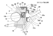
図3は、この発明の他の実施形態にかかるセンサ付軸受装置の要部拡大断面図を示す。この実施形態は、図1,図2と共に説明した第1の実施形態において、外方部材3の外径面の抜止溝28をOリング嵌合溝38に置き換えて、外方部材3の外径面とセンサ取付部材22の嵌合筒部22aとの間に介在させる弾性体27を前記Oリング嵌合溝38に嵌合するOリングとしたものである。この実施形態におけるその他の構成,効果は、第1の実施形態と同様である。
FIG. 3: shows the principal part expanded sectional view of the bearing apparatus with a sensor concerning other embodiment of this invention. In this embodiment, in the first embodiment described with reference to FIGS. 1 and 2, the retaining
この実施形態の場合にも、前記Oリング嵌合溝38に嵌合するOリング(弾性体27)によって、外方部材3の外径面とセンサ取付部材22の嵌合筒部22aとの間が密閉されるので、センサ取付部材22で覆われる軸受内のシール性が向上し、センサ取付部材22で覆われる軸受内への水等の浸入をより確実に防止することができる。
Also in the case of this embodiment, the O-ring (elastic body 27) fitted in the O-ring
図4は、この発明のさらに他の実施形態にかかるセンサ付軸受装置の要部拡大断面図を示す。この実施形態は、図1,図2と共に説明した第1の実施形態において、外方部材3の外径面の抜止溝28を軸方向に並ぶ2列としたものである。この実施形態におけるその他の構成,効果は、第1の実施形態と同じである。
FIG. 4: shows the principal part expanded sectional view of the bearing apparatus with a sensor concerning further another embodiment of this invention. In this embodiment, in the first embodiment described with reference to FIGS. 1 and 2, the retaining
この実施形態の場合、抜止溝28が2列設けられているので、外方部材3へのセンサ取付部材22の嵌合、および弾性体27の抜け止めがより確実なものとなる。
In the case of this embodiment, since the retaining
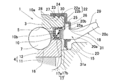
図5は、この発明のさらに他の実施形態にかかるセンサ付軸受装置の要部拡大断面図を示す。この実施形態は、図1,図2と共に説明した第1の実施形態において、センサ取付部材22の嵌合筒部22aにおける外板24を、内板23よりも軸受中央側へ延ばしている。また、センサ取付部材22の凹み板部25の底面部分25aとセンサ18との間に介在させた弾性体31を、センサ取付部材22の嵌合筒部22aまで延ばして、この弾性体31を、前記嵌合筒部22aの内板23と外板24の間にも介在させている。この実施形態におけるその他の構成,効果は、第1の実施形態と同じである。
FIG. 5: shows the principal part expanded sectional view of the bearing apparatus with a sensor concerning further another embodiment of this invention. In this embodiment, in the first embodiment described with reference to FIGS. 1 and 2, the
この実施形態の場合、センサ取付部材22の嵌合筒部22aにおける軸受中央側に向く端部で、外板24が内板23に覆い被さるように突出するため、外板24が内板23から抜け難くなり、振動等で外板24が内板23に対して緩んだり、不足に脱落することが防止される。また、外板24と内板23との重なり面から水等が侵入することが防止される。また、センサ取付部材22の凹み板部25の底面部分25aとセンサ18の間に介在させた弾性体31をセンサ取付部材22の嵌合筒部22aまで延ばして、嵌合筒部22aの内板23と外板24の間にも介在させているので、嵌合筒部22aにおける内板23と外板24の積層部の密閉性が増し、この積層部から水等がセンサ取付部材22のセンサ設置部へ浸入することが、より確実に防止される。弾性体31が外板24の内面に接着されていると、弾性体31が外板24よりも引っ込んだ内板23の先端に引っ掛かるため、外板24が内板23に対してより一層抜け難くなる。
In the case of this embodiment, the
図6は、この発明のさらに他の実施形態にかかるセンサ付軸受装置の要部拡大断面図を示す。この実施形態は、図5に示す実施形態において、外方部材3の外径面に設ける抜止溝28を、断面鋸歯状のものから断面半円状のものに置き換えたものである。弾性体27の内周面には、抜止溝28と略同一断面形状の突条が形成されていて、この突条が抜止溝28に嵌まり込む。この実施形態におけるその他の構成,効果は、図5の実施形態と同じである。
FIG. 6: shows the principal part expanded sectional view of the bearing apparatus with a sensor concerning further another embodiment of this invention. In this embodiment, in the embodiment shown in FIG. 5, the retaining
図7,図8は、この発明のさらに他の実施形態を示す。この実施形態は、図1,図2と共に説明した第1の実施形態において、ハブ輪11に嵌合させた内輪12を、ハブ輪11の後端を加締た加締部分11bによってハブ輪11に固定したものである。センサ取付部材22に設けられた弾性体31のリップ部31aは、内方部材4における上記ハブ輪11の加締部分11bに摺接するようにしてある。なお、リップ部31aは、内方部材4の端面に先端が摺接するものとしても良い。
この構成の場合は、弾性体31のリップ部31aの接触が等速ジョイントの結合状態に依存せず、この車輪用軸受装置の車体への取付作業が簡単である。この実施形態におけるその他の構成,効果は、第1の実施形態と同様である。
7 and 8 show still another embodiment of the present invention. In this embodiment, in the first embodiment described with reference to FIGS. 1 and 2, the
In the case of this configuration, the contact of the
なお、上記各実施形態は、外方部材3の外径面とセンサ取付部材22の嵌合筒部22aとの間に弾性体27を介在させた場合について説明したが、この位置の弾性体27に代えて、またはこの位置に弾性体27を介在させると共に、外方部材3の端面とセンサ取付部材22の側板部22bとの間に弾性体(図示せず)を介在させても良い。
また、上記各実施形態は、車輪用軸受装置に適用した場合につき説明したが、この発明は回転センサ部を有するラジアル型の転がり軸受一般に適用することができる。
また、上記各実施形態において、エンコーダ17およびセンサ部18は磁気式のものとしたが、光学式のものであっても良い。
In addition, although each said embodiment demonstrated the case where the
Moreover, although each said embodiment demonstrated the case where it applied to the wheel bearing apparatus, this invention is applicable to the radial type rolling bearing which has a rotation sensor part generally.
In the above embodiments, the
1…軸受部
2…回転センサ部
3…外方部材
4…内方部材
7…転動体
17…エンコーダ
18…センサ
22…センサ取付部材
22a…嵌合筒部
22b…側板部
23…内板
24…外板
25…凹み板部
25a…底面部分
26…対向板部
27…弾性体
28…抜止溝
38…Oリング嵌合溝
31a…リップ部
DESCRIPTION OF
Claims (6)
前記外方部材の外径面に嵌合する嵌合筒部、および前記外方部材の端面に接して軸方向に位置決めされる側板部を有するセンサ取付部材を設け、このセンサ取付部材の前記側板部に、内面側が凹む凹み板部とこの凹み板部の底面部分に対面する対向板部とを設け、これら凹み板部の底面部分と前記対向板部との間に前記センサを挟み込み状態に取付け、前記外方部材の外径面と前記センサ取付部材の前記嵌合筒部との間、および前記外方部材の端面と前記センサ取付部材の側板部との間の少なくとも一方に弾性体を介在させたことを特徴とするセンサ付軸受装置。 An outer member having a raceway surface on the inner periphery, an inner member having a raceway surface facing the raceway surface, a bearing portion having a rolling element interposed between the raceway surfaces, and an end portion of the inner member A sensor-equipped bearing device comprising: an encoder attached to the rotation sensor portion; and a rotation sensor portion having a sensor attached to an end portion of the outer member facing the encoder.
A sensor mounting member having a fitting tube portion that fits to the outer diameter surface of the outer member and a side plate portion that is positioned in the axial direction in contact with the end surface of the outer member is provided, and the side plate of the sensor mounting member Are provided with a concave plate portion whose inner surface side is recessed and a counter plate portion facing the bottom surface portion of the concave plate portion, and the sensor is sandwiched between the bottom surface portion of the concave plate portion and the counter plate portion. An elastic body is interposed between at least one of the outer diameter surface of the outer member and the fitting tube portion of the sensor mounting member and between the end surface of the outer member and the side plate portion of the sensor mounting member. A sensor-equipped bearing device characterized by being made.
Priority Applications (1)
| Application Number | Priority Date | Filing Date | Title |
|---|---|---|---|
| JP2004115347A JP4508704B2 (en) | 2004-04-09 | 2004-04-09 | Bearing device with sensor |
Applications Claiming Priority (1)
| Application Number | Priority Date | Filing Date | Title |
|---|---|---|---|
| JP2004115347A JP4508704B2 (en) | 2004-04-09 | 2004-04-09 | Bearing device with sensor |
Publications (2)
| Publication Number | Publication Date |
|---|---|
| JP2005299768A true JP2005299768A (en) | 2005-10-27 |
| JP4508704B2 JP4508704B2 (en) | 2010-07-21 |
Family
ID=35331547
Family Applications (1)
| Application Number | Title | Priority Date | Filing Date |
|---|---|---|---|
| JP2004115347A Expired - Fee Related JP4508704B2 (en) | 2004-04-09 | 2004-04-09 | Bearing device with sensor |
Country Status (1)
| Country | Link |
|---|---|
| JP (1) | JP4508704B2 (en) |
Cited By (9)
| Publication number | Priority date | Publication date | Assignee | Title |
|---|---|---|---|---|
| WO2008136169A1 (en) * | 2007-04-13 | 2008-11-13 | Ntn Corporation | Bearing device adapted for use in wheel and having rotational speed detector |
| WO2009011340A1 (en) * | 2007-07-17 | 2009-01-22 | Nsk Ltd. | Hub unit bearing |
| JP2009097660A (en) * | 2007-10-18 | 2009-05-07 | Jtekt Corp | Rolling bearing device with sensor |
| JP2009197941A (en) * | 2008-02-22 | 2009-09-03 | Ntn Corp | Wheel bearing device with rotation speed detector |
| JP2010180955A (en) * | 2009-02-05 | 2010-08-19 | Jtekt Corp | Sealing structure and bearing device |
| WO2011115252A1 (en) * | 2010-03-18 | 2011-09-22 | Ntn株式会社 | Wheel bearing device equipped with rotational speed detector |
| JP2012036997A (en) * | 2010-08-09 | 2012-02-23 | Nsk Ltd | Rolling bearing unit with encoder |
| US8123410B2 (en) | 2007-11-08 | 2012-02-28 | Jtekt Corporation | Rolling bearing device |
| EP2752308A1 (en) * | 2013-01-08 | 2014-07-09 | Aktiebolaget SKF | Rolling bearing unit with an encoder and protective cover for a vehicle wheel hub |
Citations (6)
| Publication number | Priority date | Publication date | Assignee | Title |
|---|---|---|---|---|
| JPS60143002U (en) * | 1984-03-02 | 1985-09-21 | ダイハツ工業株式会社 | Wheel bearing seal structure |
| JPH0527335U (en) * | 1991-09-13 | 1993-04-09 | 日本精工株式会社 | Rolling bearing unit with sensor |
| JPH09236611A (en) * | 1996-02-29 | 1997-09-09 | Nippon Seiko Kk | Sensor mounting part of rolling bearing unit with rotation speed detector |
| JP2002214245A (en) * | 2001-01-16 | 2002-07-31 | Nsk Ltd | Rolling bearing unit with rotation speed detector |
| JP2003262645A (en) * | 2002-03-08 | 2003-09-19 | Ntn Corp | Rotation detector and antilock braking device using the same |
| JP2003262647A (en) * | 2002-03-08 | 2003-09-19 | Ntn Corp | Rotation detector and bearing unit for wheel mounting the same |
-
2004
- 2004-04-09 JP JP2004115347A patent/JP4508704B2/en not_active Expired - Fee Related
Patent Citations (6)
| Publication number | Priority date | Publication date | Assignee | Title |
|---|---|---|---|---|
| JPS60143002U (en) * | 1984-03-02 | 1985-09-21 | ダイハツ工業株式会社 | Wheel bearing seal structure |
| JPH0527335U (en) * | 1991-09-13 | 1993-04-09 | 日本精工株式会社 | Rolling bearing unit with sensor |
| JPH09236611A (en) * | 1996-02-29 | 1997-09-09 | Nippon Seiko Kk | Sensor mounting part of rolling bearing unit with rotation speed detector |
| JP2002214245A (en) * | 2001-01-16 | 2002-07-31 | Nsk Ltd | Rolling bearing unit with rotation speed detector |
| JP2003262645A (en) * | 2002-03-08 | 2003-09-19 | Ntn Corp | Rotation detector and antilock braking device using the same |
| JP2003262647A (en) * | 2002-03-08 | 2003-09-19 | Ntn Corp | Rotation detector and bearing unit for wheel mounting the same |
Cited By (15)
| Publication number | Priority date | Publication date | Assignee | Title |
|---|---|---|---|---|
| WO2008136169A1 (en) * | 2007-04-13 | 2008-11-13 | Ntn Corporation | Bearing device adapted for use in wheel and having rotational speed detector |
| WO2009011340A1 (en) * | 2007-07-17 | 2009-01-22 | Nsk Ltd. | Hub unit bearing |
| JP2009024732A (en) * | 2007-07-17 | 2009-02-05 | Nsk Ltd | Hub unit bearing |
| US8419288B2 (en) | 2007-07-17 | 2013-04-16 | Nsk Ltd. | Hub unit bearing |
| JP2009097660A (en) * | 2007-10-18 | 2009-05-07 | Jtekt Corp | Rolling bearing device with sensor |
| US8123410B2 (en) | 2007-11-08 | 2012-02-28 | Jtekt Corporation | Rolling bearing device |
| JP2009197941A (en) * | 2008-02-22 | 2009-09-03 | Ntn Corp | Wheel bearing device with rotation speed detector |
| JP2010180955A (en) * | 2009-02-05 | 2010-08-19 | Jtekt Corp | Sealing structure and bearing device |
| WO2011115252A1 (en) * | 2010-03-18 | 2011-09-22 | Ntn株式会社 | Wheel bearing device equipped with rotational speed detector |
| JP2011196425A (en) * | 2010-03-18 | 2011-10-06 | Ntn Corp | Bearing arrangement for wheel with rotational speed detection device |
| US8585298B2 (en) | 2010-03-18 | 2013-11-19 | Ntn Corporation | Wheel bearing apparatus incorporated with a rotation speed detecting apparatus |
| JP2012036997A (en) * | 2010-08-09 | 2012-02-23 | Nsk Ltd | Rolling bearing unit with encoder |
| EP2752308A1 (en) * | 2013-01-08 | 2014-07-09 | Aktiebolaget SKF | Rolling bearing unit with an encoder and protective cover for a vehicle wheel hub |
| ITTO20130006A1 (en) * | 2013-01-08 | 2014-07-09 | Skf Ab | BEARING GROUP FOR A WHEEL OF A VEHICLE |
| US9016949B2 (en) | 2013-01-08 | 2015-04-28 | Aktiebolaget Skf | Bearing unit for a vehicle wheel |
Also Published As
| Publication number | Publication date |
|---|---|
| JP4508704B2 (en) | 2010-07-21 |
Similar Documents
| Publication | Publication Date | Title |
|---|---|---|
| WO2005078457A1 (en) | Bearing device with sensor | |
| US20110089642A1 (en) | Bearing Seal | |
| JPH0555070U (en) | Rotational speed detector for wheel bearings | |
| JP2009115257A (en) | Rolling bearing device | |
| JP4508704B2 (en) | Bearing device with sensor | |
| JP2004176827A (en) | Protective cap of bearing device for wheel | |
| US6918596B2 (en) | Seal with integrated sealing and rotation measuring capabilities | |
| JP2005265826A (en) | Bearing device with sensor | |
| JP2004011827A (en) | Shield structure with magnetic encoder of bearing for wheel | |
| JP2005331429A (en) | Rolling bearing unit with encoder | |
| JPH11174068A (en) | Rolling bearing unit with encoder | |
| JP5067718B2 (en) | Rolling bearing device with sensor | |
| JP2004211832A (en) | Bearing device corresponding to sensor | |
| JP5098730B2 (en) | Rotational speed detection device for motorcycle wheels | |
| JP2007120560A (en) | Wheel bearing device | |
| EP1780549B1 (en) | Seal device with sensor and rolling bearing device using the same | |
| JP5035754B2 (en) | Rolling bearing device with sensor | |
| JP4026557B2 (en) | Pulsar ring and seal device for rotation detection | |
| JP2010048290A (en) | Sealing device with magnetic encoder | |
| JP5196180B2 (en) | Rolling bearing device with sensor | |
| JP2004190736A (en) | Bearing device for wheel | |
| JP4656917B2 (en) | Wheel bearing device with rotation speed detector | |
| JP2008267423A (en) | Bearing seal | |
| JP2008215921A (en) | Magnetized pulsar ring and sensor-equipped rolling bearing device using the same | |
| JP2006064145A (en) | Bearing device for wheel |
Legal Events
| Date | Code | Title | Description |
|---|---|---|---|
| A621 | Written request for application examination |
Free format text: JAPANESE INTERMEDIATE CODE: A621 Effective date: 20070404 |
|
| A977 | Report on retrieval |
Free format text: JAPANESE INTERMEDIATE CODE: A971007 Effective date: 20090827 |
|
| A131 | Notification of reasons for refusal |
Free format text: JAPANESE INTERMEDIATE CODE: A131 Effective date: 20090915 |
|
| A521 | Written amendment |
Free format text: JAPANESE INTERMEDIATE CODE: A523 Effective date: 20091112 |
|
| TRDD | Decision of grant or rejection written | ||
| A01 | Written decision to grant a patent or to grant a registration (utility model) |
Free format text: JAPANESE INTERMEDIATE CODE: A01 Effective date: 20100427 |
|
| A01 | Written decision to grant a patent or to grant a registration (utility model) |
Free format text: JAPANESE INTERMEDIATE CODE: A01 |
|
| A61 | First payment of annual fees (during grant procedure) |
Free format text: JAPANESE INTERMEDIATE CODE: A61 Effective date: 20100427 |
|
| FPAY | Renewal fee payment (event date is renewal date of database) |
Free format text: PAYMENT UNTIL: 20130514 Year of fee payment: 3 |
|
| R150 | Certificate of patent or registration of utility model |
Free format text: JAPANESE INTERMEDIATE CODE: R150 |
|
| LAPS | Cancellation because of no payment of annual fees |