EP4534378A2 - Vorrichtung und verfahren zur steuerung der fahrzeugbewegung - Google Patents
Vorrichtung und verfahren zur steuerung der fahrzeugbewegung Download PDFInfo
- Publication number
- EP4534378A2 EP4534378A2 EP25159985.8A EP25159985A EP4534378A2 EP 4534378 A2 EP4534378 A2 EP 4534378A2 EP 25159985 A EP25159985 A EP 25159985A EP 4534378 A2 EP4534378 A2 EP 4534378A2
- Authority
- EP
- European Patent Office
- Prior art keywords
- vehicle
- terrain
- signal
- controller
- manoeuvre
- Prior art date
- Legal status (The legal status is an assumption and is not a legal conclusion. Google has not performed a legal analysis and makes no representation as to the accuracy of the status listed.)
- Pending
Links
Images


Classifications
-
- B—PERFORMING OPERATIONS; TRANSPORTING
- B60—VEHICLES IN GENERAL
- B60W—CONJOINT CONTROL OF VEHICLE SUB-UNITS OF DIFFERENT TYPE OR DIFFERENT FUNCTION; CONTROL SYSTEMS SPECIALLY ADAPTED FOR HYBRID VEHICLES; ROAD VEHICLE DRIVE CONTROL SYSTEMS FOR PURPOSES NOT RELATED TO THE CONTROL OF A PARTICULAR SUB-UNIT
- B60W30/00—Purposes of road vehicle drive control systems not related to the control of a particular sub-unit, e.g. of systems using conjoint control of vehicle sub-units
- B60W30/06—Automatic manoeuvring for parking
-
- B—PERFORMING OPERATIONS; TRANSPORTING
- B60—VEHICLES IN GENERAL
- B60W—CONJOINT CONTROL OF VEHICLE SUB-UNITS OF DIFFERENT TYPE OR DIFFERENT FUNCTION; CONTROL SYSTEMS SPECIALLY ADAPTED FOR HYBRID VEHICLES; ROAD VEHICLE DRIVE CONTROL SYSTEMS FOR PURPOSES NOT RELATED TO THE CONTROL OF A PARTICULAR SUB-UNIT
- B60W60/00—Drive control systems specially adapted for autonomous road vehicles
- B60W60/001—Planning or execution of driving tasks
-
- B—PERFORMING OPERATIONS; TRANSPORTING
- B62—LAND VEHICLES FOR TRAVELLING OTHERWISE THAN ON RAILS
- B62D—MOTOR VEHICLES; TRAILERS
- B62D15/00—Steering not otherwise provided for
- B62D15/02—Steering position indicators ; Steering position determination; Steering aids
- B62D15/027—Parking aids, e.g. instruction means
- B62D15/0285—Parking performed automatically
-
- G—PHYSICS
- G06—COMPUTING OR CALCULATING; COUNTING
- G06F—ELECTRIC DIGITAL DATA PROCESSING
- G06F9/00—Arrangements for program control, e.g. control units
- G06F9/06—Arrangements for program control, e.g. control units using stored programs, i.e. using an internal store of processing equipment to receive or retain programs
- G06F9/30—Arrangements for executing machine instructions, e.g. instruction decode
- G06F9/38—Concurrent instruction execution, e.g. pipeline or look ahead
- G06F9/3836—Instruction issuing, e.g. dynamic instruction scheduling or out of order instruction execution
- G06F9/3838—Dependency mechanisms, e.g. register scoreboarding
-
- G—PHYSICS
- G06—COMPUTING OR CALCULATING; COUNTING
- G06V—IMAGE OR VIDEO RECOGNITION OR UNDERSTANDING
- G06V20/00—Scenes; Scene-specific elements
- G06V20/50—Context or environment of the image
- G06V20/56—Context or environment of the image exterior to a vehicle by using sensors mounted on the vehicle
-
- G—PHYSICS
- G08—SIGNALLING
- G08G—TRAFFIC CONTROL SYSTEMS
- G08G1/00—Traffic control systems for road vehicles
- G08G1/14—Traffic control systems for road vehicles indicating individual free spaces in parking areas
- G08G1/145—Traffic control systems for road vehicles indicating individual free spaces in parking areas where the indication depends on the parking areas
- G08G1/148—Management of a network of parking areas
-
- G—PHYSICS
- G08—SIGNALLING
- G08G—TRAFFIC CONTROL SYSTEMS
- G08G1/00—Traffic control systems for road vehicles
- G08G1/16—Anti-collision systems
- G08G1/168—Driving aids for parking, e.g. acoustic or visual feedback on parking space
-
- B—PERFORMING OPERATIONS; TRANSPORTING
- B60—VEHICLES IN GENERAL
- B60W—CONJOINT CONTROL OF VEHICLE SUB-UNITS OF DIFFERENT TYPE OR DIFFERENT FUNCTION; CONTROL SYSTEMS SPECIALLY ADAPTED FOR HYBRID VEHICLES; ROAD VEHICLE DRIVE CONTROL SYSTEMS FOR PURPOSES NOT RELATED TO THE CONTROL OF A PARTICULAR SUB-UNIT
- B60W2554/00—Input parameters relating to objects
- B60W2554/20—Static objects
-
- B—PERFORMING OPERATIONS; TRANSPORTING
- B60—VEHICLES IN GENERAL
- B60W—CONJOINT CONTROL OF VEHICLE SUB-UNITS OF DIFFERENT TYPE OR DIFFERENT FUNCTION; CONTROL SYSTEMS SPECIALLY ADAPTED FOR HYBRID VEHICLES; ROAD VEHICLE DRIVE CONTROL SYSTEMS FOR PURPOSES NOT RELATED TO THE CONTROL OF A PARTICULAR SUB-UNIT
- B60W2554/00—Input parameters relating to objects
- B60W2554/40—Dynamic objects, e.g. animals, windblown objects
- B60W2554/404—Characteristics
- B60W2554/4041—Position
Definitions
- the present disclosure relates to controlling movement of a vehicle and particularly, but not exclusively, to controlling performance of a defined manoeuvre by the vehicle. Aspects of the invention relate to a controller, to a system, to a method, to a vehicle and to computer software.
- the present disclosure relates also to determining an orientation of a completed position of a vehicle, particularly, but not exclusively, to determining an orientation of a defined manoeuvre completed position of the vehicle. Aspects of the invention relate to a controller, to a system, to a method, to a vehicle and to computer software.
- a vehicle to perform a defined manoeuvre, such as an automatic, or semi-autonomous, parking manoeuvre.
- a user typically instructs the vehicle to identify a possible defined manoeuvre when the owner is ready, such as when the owner is looking for or at a parking location.
- the vehicle may be instructed to perform the manoeuvre remotely e.g. via a mobile device at which a user input is received to instruct the manoeuvre.
- Environment sensing means of the vehicle are used to determine a location of features in a vicinity of the vehicle such as, although not exclusively, markings, walls, posts, other vehicles etc.
- the vehicle may then be instructed, such as via the mobile device or other input medium, to move to a parked location in relation to the features. For example, it may be desired for a vehicle to move into a parking space bounded by the features.
- the environment sensing means determines a distance between the vehicle and the object and the automatic parking manoeuvre is performed to leave the vehicle a separation distance from the object. For example, the vehicle may be reversed towards the feature, until an appropriate separation distance is determined by the environment sensing means.
- the vehicle is parked in the middle of the space -for example, to be positioned in the centre of a garage. Once the vehicle has reached a completed parked position, the vehicle is switched off, typically with a parking brake applied.
- the features bounding a parking space can inhibit access to or from the vehicle.
- a wall adjacent a parking space can impede the opening of a vehicle door, impeding or preventing access via that door.
- Driver preference can be to leave the vehicle steered wheels straightened when parked, such as to appear tidy or prevent a vehicle wheel from protruding laterally. In other situations, it is preferred or even required to cramp vehicle wheels on sloping terrain of any gradient.
- the defined manoeuvre is typically performed in various ambient conditions, such as irrespective of weather or lighting.
- a parking space may be too narrow to allow the vehicle to manoeuvre into or out of the parking space, such as with sufficient clearance, or even be too narrow to receive the vehicle as such (e.g. narrower than a maximum width of the vehicle).
- Defined manoeuvres can be performed on different terrains, such as differing ground surface type or smoothness.
- the vehicle may be instructed to perform the manoeuvre remotely e.g. via a mobile device at which a user input is received to instruct the manoeuvre.
- the vehicle may be instructed to perform the manoeuvre with the user in the vehicle.
- Performance of the manoeuvre generally moves the vehicle from a start position, such as outside the parking space, to a completed position, such as in the parking space. If the vehicle has reached a completed parked position, the user can switch the vehicle off, typically with a parking brake applied.
- the user can control the vehicle, such as to drive manually. If the vehicle has reached a completed parked position, the user can switch the vehicle off, typically with a parking brake applied.
- a controller arranged to operably cause a vehicle to perform at least a portion of a defined manoeuvre in dependence on a terrain.
- a controller comprising: input means for receiving a terrain signal indicative of a terrain in a vicinity of a vehicle; output means for outputting a manoeuvre signal to cause the vehicle to perform a defined manoeuvre; and control means arranged to control the output means in dependence on the terrain signal.
- the vehicle may be caused to adapt the performance of the defined manoeuvre to suit the terrain.
- the defined manoeuvre may comprise a parking manoeuvre.
- the parking manoeuvre may comprise an in-parking manoeuvre, such as parking into a space to a stationary position.
- the parking manoeuvre may comprise an un-parking manoeuvre, such as parking out of a space from a stationary position.
- a defined manoeuvre completed position may comprise a parked position.
- the control means may be arranged to control the output means to cause the vehicle to perform at least a portion of the defined manoeuvre in accordance with a vehicle movement control profile determined in dependence on the terrain signal.
- the vehicle may be caused to perform the defined manoeuvre in a controlled manner appropriate for the terrain.
- the vehicle movement control profile may comprise a speed parameter.
- the speed parameter may be indicative of a first order speed parameter.
- the vehicle may be caused to perform the defined manoeuvre with a vehicle speed appropriate for the terrain.
- the control means may be arranged to select the vehicle movement control profile in dependence on a categorisation of the terrain.
- the vehicle may select, automatically or otherwise, parameters for performance of the defined manoeuvre associated with predetermined categories of terrain or terrains.
- control means may be arranged to control the output means in dependence on a topography signal indicative of a topography in the vicinity of the vehicle.
- the speed parameter may be indicative of an acceleration of the vehicle.
- the vehicle may be caused to perform the defined manoeuvre with an appropriate acceleration, such as to perform the defined manoeuvre efficiently and/or without undue acceleration of the vehicle or content thereof or an occupant.
- the speed parameter comprises a maximum speed parameter.
- the vehicle may be caused to perform the defined manoeuvre with a maximum speed, acceleration and/or jerk; such that the defined manoeuvre is performed efficiently, and/or physically and/or psychologically appropriate for a user.
- the maximum speed parameter of a vehicle movement control profile corresponding to a first terrain may be less than the maximum speed parameter of a vehicle movement control profile corresponding to a second terrain.
- the maximum speed parameter can be varied to suit a variation in the terrain.
- the maximum speed parameter of a vehicle movement control profile corresponding to an off-road terrain may be less than the maximum speed parameter of a vehicle movement control profile corresponding to an on-road terrain.
- the maximum speed parameter may be reduced to accommodate differences in forces.
- the maximum speed parameter of the vehicle movement control profile corresponding to an off-road terrain may be the same or greater than the maximum speed parameter of the vehicle movement control profile corresponding to an on-road terrain. For example, there may be an increased maximum jerk for the vehicle movement control profile corresponding to the off-road terrain, such as where a user may be accustomed to or expect an increased jerk (e.g. particularly associated with a bumpy terrain).
- the movement control profile may be dependent upon an ambient condition in a vicinity of the vehicle.
- the vehicle may be caused to adapt the performance of the defined manoeuvre to suit the ambient condition.
- the controller may comprise a second input means for receiving a request signal indicative of a received signal indicative of a user request.
- the request signal may be indicative of a wired or a wirelessly received signal indicative of a user request, such as from a user's mobile device.
- this may allow the vehicle to be effectively instructed from a user's mobile device, such as remotely instructed.
- the user may comprise an occupant.
- the user may comprise a driver of the vehicle.
- the user may be located in the vehicle.
- the user may be located out of the vehicle, such as for at least a portion of performance of the defined manoeuvre.
- the vehicle may comprise one or more non-driver occupants.
- one or more users and/or occupants may be located in and/or out of the vehicle.
- the control means may be arranged to determine a vacancy.
- the control means may be arranged to define at least one vehicle envelope within the vacancy, the vehicle envelope being suitable for receiving the vehicle in the defined manoeuvre completed position.
- the control means may be arranged to define within the vacancy at least one defined manoeuvre completed position for the vehicle.
- the vehicle envelope may comprise a target position suitable for receiving the vehicle in the defined manoeuvre completed position.
- the vehicle envelope may comprise a target defined manoeuvre completed position.
- the vehicle envelope may be determined in dependence on a one-dimensional property and/or measurement and/or estimation.
- the vehicle envelope may be determined in dependence on the environment signal being indicative of a length, such as an unobstructed length between features, the unobstructed length being sufficiently long for receiving the vehicle in the defined manoeuvre completed position.
- the vehicle envelope may be determined in dependence on a two-dimensional property and/or measurement and/or estimation.
- the vehicle envelope may be determined in dependence on the environment signal being indicative of a length, such as between features, wherein along that length there is no obstruction within a particular width or breadth perpendicular to the length.
- the particular width or bready may correspond to at least a width or breadth of the vehicle, such as a vehicle width when the vehicle is parked and in a closed configuration, such as with vehicle aperture members closed.
- the particular width or breadth may correspond to at least a length of the vehicle, such as a vehicle length when the vehicle is parked and in the closed configuration in a perpendicular or parking lot or fishbone diagonal parked position.
- the vehicle envelope may comprise at least one dimension of a parking area and the defined manoeuvre completed position may be a parked position.
- the vehicle envelope may correspond to a predefined parking space.
- the vehicle envelope may comprise a target length, area or volume for receiving the vehicle in or on in the defined manoeuvre completed position.
- the control means may be arranged to define at least two vehicle envelopes within the vacancy, each vehicle envelope comprising a discrete defined manoeuvre completed position that is offset within the vacancy.
- the two vehicle envelopes may be non-overlapping. Alternatively, the two vehicle envelopes may be overlapping.
- the two vehicle envelopes may extend in respective longitudinal directions adjacent and parallel each other.
- the two vehicle envelopes may extend along a same longitudinal axis, with a first vehicle envelope being longitudinally displaced along the longitudinal axis from a second vehicle envelope.
- the vehicle envelops may be arranged with non-parallel longitudinal axes, such as with a first vehicle envelope having a longitudinal axis perpendicular to a longitudinal axis of a second vehicle envelope.
- a system comprising: the controller as described above, arranged to receive the terrain signal and to output the manoeuvre signal; and actuator means for receiving the manoeuvre signal to cause the vehicle to perform the defined manoeuvre in dependence on the terrain signal.
- the system may comprise: terrain sensing means for determining the terrain in the vicinity of the vehicle and outputting the terrain signal indicative thereof.
- the system may comprise: environment sensing means for determining a location of one or more features in the vicinity of the vehicle and outputting an environment signal indicative thereof.
- the terrain sensing means may comprise the environment sensing means.
- the control means may be arranged to control the output means to cause the vehicle to perform at least a portion of the defined manoeuvre in accordance with a vehicle movement control profile determined in dependence on the terrain signal.
- the control means may be arranged to select a vehicle movement profile in dependence on the one or more features.
- the control means may be arranged to select the vehicle movement control profile in dependence upon a location of the vehicle.
- the control means may be arranged to select the vehicle movement control profile for performing the defined manoeuvre in dependence upon a drive mode of the vehicle.
- the control means may be arranged to select the vehicle movement control profile for performing the defined manoeuvre in dependence upon a presence of an occupant in the vehicle.
- the control means may be arranged to receive an ambient condition signal indicative of at least one ambient condition in a vicinity of the vehicle.
- the control means may be arranged to select the vehicle movement control profile for performing the defined manoeuvre in dependence upon the ambient condition signal.
- the system may comprise: receiver means for receiving a signal indicative of a user request for vehicle movement and outputting a request signal in dependence thereon.
- the receiver means may be for wirelessly receiving a signal from a mobile user device indicative of the user request.
- the system may comprise ambient condition sensing means for determining the one or more ambient conditions in the vicinity of the vehicle and outputting the ambient condition signal indicative thereof.
- a method of controlling movement of a vehicle to perform a defined manoeuvre comprising: receiving a terrain signal indicative of a terrain in a vicinity of the vehicle; and controlling an output means in dependence on the terrain signal such that at least a portion of the defined manoeuvre is performed in dependence on the terrain in the vicinity of the vehicle.
- the method may comprise determining the terrain with a terrain sensing means.
- the method may comprise controlling the output means in dependence on the terrain signal such that at least a portion of the defined manoeuvre is performed in accordance with a vehicle movement control profile dependent on the terrain in the vicinity of the vehicle.
- the method may comprise selecting the vehicle movement control profile in dependence upon a vehicle drive mode.
- the method may comprise selecting the vehicle movement control profile in dependence on a presence of an occupant in the vehicle.
- the method may comprise determining an ambient condition in the vicinity of the vehicle and selecting the vehicle movement control profile in dependence on the ambient condition.
- the method may comprise determining a location of one or more features in a vicinity of the vehicle with an environment sensing means; and selecting the vehicle movement control profile in dependence upon the one or more features.
- the method may comprise receiving a signal indicative of a user request to perform the defined manoeuvre.
- the method may comprise receiving the signal from a mobile device indicative of the user request to perform the defined manoeuvre.
- controllers described herein may suitably comprise a control unit or computational device having one or more electronic processors.
- the system may comprise a single control unit or electronic controller or alternatively different functions of the controller may be embodied in, or hosted in, different control units or controllers.
- controller or “control unit” will be understood to include both a single control unit or controller and a plurality of control units or controllers in a control system collectively operating to provide any stated control functionality.
- a suitable set of instructions may be provided which, when executed, cause said control unit or computational device to implement the control techniques specified herein.
- the set of instructions may suitably be embedded in said one or more electronic processors.
- the set of instructions may be provided as software saved on one or more memory associated with said controller to be executed on said computational device.
- a first controller may be implemented in software run on one or more processors.
- One or more other controllers may be implemented in software run on one or more processors, optionally the same one or more processors as the first controller. Other suitable arrangements may also be used.
- Figure 1 illustrates a vehicle 110 according to an embodiment of the invention.
- the vehicle 110 is shown at a defined manoeuvre start position in advance of performing a defined manoeuvre, such as to a parked positioned of the vehicle 110.
- the vehicle is shown here with a longitudinal axis 112 and having a vehicle forward direction, indicated by arrow 114.
- a terrain 135 in the vicinity of the vehicle is shown, such as a road ground surface.
- the terrain is not limited to being a road ground surface and may include, for example, another load-bearing surface such as an offroad ground surface.
- the defined manoeuvre may be a manoeuvre of the vehicle 110 which is performed automatically by the vehicle 110 i.e. under control of one or more systems of the vehicle 110.
- the defined manoeuvre may be considered to be performed automatically by the vehicle 110, or at least semi autonomously.
- the defined manoeuvre may be a parking manoeuvre to control the vehicle 110 to drive into a parking structure or parking place.
- the terrain may be such as to have an actual and/or a perceived effect on the performance of the defined manoeuvre, such as physically and/or psychologically influencing a user's experience of performance of the defined manoeuvre.
- Embodiments of the present invention aim to ameliorate one or both of these problems.
- Figure 2 illustrates a controller 200 or control unit 200 according to an embodiment of the invention, such as comprised in the vehicle 110 of Figure 1 .
- the controller 200 comprises a control means 210, input means 230 and output means 240.
- the controller comprises a memory means 220 such as one or more memory devices 220 for storing data therein.
- the output means 240 may comprise an electrical output for outputting a manoeuvre signal.
- the manoeuvre signal represents an instruction for the vehicle 110 to move.
- the input means 230 is for receiving a terrain signal indicative of the terrain 135 in the vicinity of the vehicle 110.
- the control means 210 is arranged to control the output means 240 to cause the vehicle 110 to perform at least a portion of the defined manoeuvre in dependence on the terrain signal.
- the control means 210 is arranged to control the output means 240 to cause the vehicle 110 to perform at least a portion of the defined manoeuvre in accordance with a vehicle movement control profile determined in dependence on the terrain signal. Accordingly, the vehicle 110 is caused to perform the defined manoeuvre in a controlled manner appropriate for the terrain 135.
- the vehicle movement control profile comprises a speed parameter.
- the speed parameter is indicative of a first order speed parameter.
- the control means 6210 is arranged to select the vehicle movement control profile in dependence on a categorisation of the terrain 135. Accordingly, the control means 210 of the vehicle 110 automatically selects parameters for performance of the defined manoeuvre associated with predetermined categories of terrain or terrains 135.
- the speed parameter is indicative of a speed, an acceleration and a jerk of the vehicle 110, jerk being a rate of change of acceleration of the vehicle 110. Accordingly, the vehicle 110 is caused to perform the defined manoeuvre with an appropriate speed, acceleration and jerk; such as to perform the defined manoeuvre efficiently and/or without undue acceleration of the vehicle 110 or a user or content thereof.
- the vehicle movement control profile is selected to provide reduced speed parameters, such as reduced maximum speed, maximum acceleration and maximum jerk.
- the controller 200 adapts the performance of the defined manoeuvre to reduce the possibility of the vehicle 110 slipping or at least reduce a user's perception of the possibility of the vehicle 110 slipping.
- the vehicle 110 is caused to perform the defined manoeuvre with an appropriate speed, acceleration and rate of change of acceleration, which is physically and psychologically suited to the terrain 135 to be comfortable for the user.
- the maximum speed parameter of the vehicle movement control profile corresponding to the slippy terrain 135 of Figure 1 may be less than the maximum speed parameter of a vehicle movement control profile corresponding to a high-grip terrain, such as a dry, stable asphalt road surface. Accordingly, the maximum speed parameter can be varied to suit a variation in the terrain 135. It will be appreciated that the vehicle movement control profile can be varied during the performance of the defined manoeuvre: for example, if the terrain changes (e.g. if the vehicle 110 moves onto a different terrain 135 subsequent to initiation of the defined manoeuvre).
- the vehicle 110 comprises environment sensing means for determining a location of features in the vicinity of the vehicle 110.
- the environment sensing means may comprise one or more sensing devices or imaging devices.
- the one or more sensing devices may emit radiation and receive radiation reflected from the features in the vicinity of the vehicle, such as ultrasonic sensing devices, although it will be appreciated that the present invention is not limited in this respect.
- Such environment sensing means have a minimum distance to which accuracy the location of the features may be determined due to, for example, a resolution of an imaging device or a signal-to-noise ratio of a sensing device.
- the environment sensing means provides the terrain signal, or at least an input therefor.
- the environment sensing means may comprise a sensor or imaging device capable of detecting a ground surface, or type thereof. Additional or alternative inputs from or for the terrain signal may include one or more of: one or more brake sensors; one or more accelerometers; one or more suspension sensors; one or more thermometers; one or more wipers; one or more traction sensors; at least one drive mode (e.g. "off-road”, "sport", “normal”, etc).
- the control means 210 can be adapted accordingly, such as to a wet terrain weather vehicle movement control profile, with a reduced speed parameter.
- the drive mode of the vehicle 110 is used in at least some examples to determine the terrain - and the control means 210 is arranged to adapt the output means 240 accordingly (e.g. to reduce the speed parameter on off-road terrain).
- the terrain signal may be at least partially dependent on a terrain sensing or measurement.
- the terrain signal may be dependent at least partially on an estimated terrain.
- the estimated terrain may be derived from one or more other parameters or statuses. For example, where a vehicle is in a geographic location, then an estimated terrain may be taken as indicative of terrain, such as based at least partially on a previous terrain sensing or estimation.
- the user typically applies a parking brake, to leave the vehicle stationary with the engine switched off.
- the control means 210 may be formed by one or more electronic processing devices such as an electronic processor.
- the processor may operably execute computer readable instructions stored in the one or more memory devices 220.
- the control means 210 is arranged to control the output means 240 to output the manoeuvre signal in dependence on the environment signal, as will be explained.
- the input means 230 and output means 240 may be combined such as by being formed by an I/O unit or interface unit.
- the controller 210 may comprise an interface to a network forming a communication bus of a vehicle.
- the interface bus may be an Internet Protocol (IP) based communication bus such as Ethernet, although embodiments of the invention are not limited in this respect.
- IP Internet Protocol
- the input means 230 comprises an electrical input for receiving the terrain signal.
- the input means 230 may comprise an electrical input for receiving an environment signal.
- the input means 230 may comprise an electrical input for receiving a request signal.
- the controller 210 comprises a second input means for receiving a request signal indicative of a received signal indicative of a user request, such as a wirelessly received signal.
- controller 200 may be arranged to perform a portion of the defined manoeuvre.
- the user may initiate the manoeuvre with control being transferred to the controller 210 thereafter to complete the defined manoeuvre.
- FIG 3 illustrates a system 300 according to an embodiment of the invention.
- the system 300 comprises the controller 210 described above and shown in Figure 2 .
- the system 300 comprises terrain sensing means 331 for determining information about a terrain in the vicinity of the vehicle 110.
- the terrain sensing means 331 is arranged to output a terrain signal indicative of the determined terrain 135.
- the terrain signal may be terrain data which may be stored in a memory.
- the terrain sensing means may comprise one or more sensing devices such as environment sensing means (e.g. imaging devices, such as cameras, or other sensing devices such as LIDAR, radar, ultrasonic devices, sonar devices etc.); thermometers; precipitation sensors; traction sensors; brake sensors. Signals output by each of the sensing devices may be used to form a representation of the terrains in the vicinity of the vehicle 110 which is stored in the memory for use by other systems of the vehicle 110.
- the terrain signal is dependent at least partially on an estimated terrain.
- the estimated terrain may be based, for example, on a geographic location, a drive mode, and/or another vehicle system in addition or instead of the terrain sensing means.
- the vehicle comprises environment sensing means for determining a location of at least one feature in the vicinity of the vehicle; and outputting an environment signal indicative thereof.
- the environment sensing means is arranged to determine a location of features such as surface markings, which may be painted lines denoting a perimeter of a parking bay, for example, or objects such as walls, posts or other vehicles in relation to which the vehicle is required to manoeuvre.
- the control means is arranged to determine an absence of features, such as a separation between obstructive features (not shown) in dependence on the environment signal. Accordingly, the control means is arranged to determine a vacancy where no features, such as no obstructive features, are located.
- the control means is arranged to determine a vehicle envelope suitable for receiving the vehicle 110 in the defined manoeuvre completed position.
- the vehicle envelope comprises a target position suitable for receiving the vehicle 110 in the defined manoeuvre completed position.
- the vehicle envelope comprises a target defined manoeuvre completed position.
- the vehicle envelope is determined in dependence on a one-dimensional property and/or measurement and/or estimation.
- the vehicle envelope can be determined in dependence on the environment signal being indicative of a length, such as an unobstructed length between features (not shown).
- the unobstructed length is sufficiently long for receiving the vehicle 110 in the defined manoeuvre completed position, the length being a separation between features that is greater than the vehicle length or width in the defined manoeuvre completed position.
- the defined manoeuvre may comprise, for example, parking in a parked position.
- the controller 210 of the system 300 here comprises defined manoeuvre means.
- the control means is arranged to control the vehicle 110 to perform at least one defined manoeuvre.
- the controller 210 may comprise a defined manoeuvre controller for controlling one or more systems of the vehicle 110 to perform one or more defined manoeuvres.
- the defined manoeuvre means may be associated with one or more actuators 350 of the vehicle 110.
- the one or more actuators 350 are provided for effecting movement of the vehicle 110.
- the actuators may comprise one or more of a power steering mechanism arranged to provide steering of wheels of the vehicle 110 in dependence on signals received from the controller 210.
- a second actuator may comprise a powered braking mechanism of the vehicle 110 which is arranged to actuate brakes of the vehicle in dependence on signals received from the controller 210.
- a third actuator comprises the powertrain of the vehicle.
- the controller 210 is arranged to control the steering of the vehicle wheel 180 relative to the feature.
- the system 300 shown here comprises a motive control means 320.
- the motive control means 320 may be a motive control unit.
- the motive control means 320 is arranged to receive the manoeuvre signal output by the controller 210.
- the motive control means 320 is associated with one or more motive units of the vehicle 110 which may form part of a powertrain (not shown) of the vehicle 110.
- the motive units may comprise one or more of an internal combustion engine and one or more electric machines of the vehicle 110.
- the powertrain is arranged to provide power, or torque, to cause movement in the longitudinal axis of the vehicle 110 i.e. forward or backward movement of the vehicle 100 in dependence on the manoeuvre signal received from the controller 210.
- the motive control means 320 is arranged to control the application of torque to one or more wheels of the vehicle 110 to move the vehicle 110 in the longitudinal axis of the vehicle i.e. to move the vehicle generally forwards or backwards.
- the torque may comprise driving torque i.e. applied in a direction of desired movement, such as forwards.
- the torque may also comprise braking torque i.e. applied to resist the driving torque.
- both driving torque and braking torque may be applied simultaneously in order to provide low-speed movement of the vehicle 110.
- the braking torque may also be applied at least partly after the driving torque in order to effect accurate movement of the vehicle 110.
- the controller 210 may communicate with the motive control means 320.
- the one or more actuators 350 can control a direction and movement of the vehicle to perform the defined manoeuvre.
- the defined manoeuvre is performed in dependence on the terrain signal provided by the terrain sensing means 331.
- the one or more defined manoeuvres which may be performed by the vehicle 110 under control of the controller 210 may comprise a parking manoeuvre, such as a parking-in manoeuvre wherein the vehicle 110 is controlled to arrive at a parked position.
- the system 300 comprises a receiver means 310 for receiving a signal 305.
- the signal 305 may be wirelessly received from a mobile device 390 associated with a person responsible for the vehicle 110.
- the signal 305 is indicative of a user request for vehicle movement of the vehicle 110.
- the receiver means 310 is arranged to output the request signal to the input means 230 of the controller 210 as described above.
- the request signal may be output by the receiver means 310 onto a communication bus of the vehicle 110 which may communicably couple the components of the system 300.
- the receiver means 310 may be in the form of a radio unit 310.
- the radio unit 310 may comprise a receiver for receiving radio signals 305 from the mobile device 390.
- the radio unit 310 may also comprise a transmitter, or may be a transceiver 310 configured to receive radio signals 305 transmitted from the mobile device 390 and transmit signals to the mobile device 390.
- the radio unit 103 and the mobile device 390 may be arranged to provide a wireless local area network, via which two-way communication may take place between the radio unit 103 and the mobile device 390.
- the radio unit 103 may be arranged to communicate by WiFi (RTM) with the mobile device 390.
- WiFi WiFi
- other radio communication standards may be used for the communication.
- communication between the radio unit 103 and the mobile device 390 is provided via Bluetooth (RTM), although other protocols or standards may be envisaged.
- the mobile device 390 may be an electronic key fob associated with the vehicle 110, such as may be used to gain entry and to activate or power up the vehicle 110.
- the mobile device 390 may, in other embodiments, be an electronic device associated with the person responsible for the vehicle 100 such as a mobile telephone, tablet, watch, wearable electronic device or other computing device associated with the person.
- the mobile device 390 is capable of receiving a user input indicating the person's desire to move the vehicle 110.
- the user input may be provided in the form of a button or key press, activation of a graphically displayed icon, a gesture or voice command. Other forms of user input may also be envisaged.
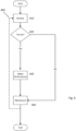
- Figure 4 illustrates a method 400 according to an embodiment of the invention.
- the method 400 is a method of controlling movement of the vehicle 110.
- the method 400 may be formed by the controller 210 and system 300 described above with reference to Figures 2 and 3 .
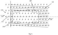
- the method 400 will be described with reference to Figure 5 as an example which corresponds broadly to the situation shown in Figure 1 .
- the method 400 broadly comprises steps of receiving 410 the terrain signal from the terrain sensing means 331 which is indicative of a terrain 135 in a vicinity of the vehicle 110 and, in dependence thereon, controlling 440 the vehicle's 110 performance of a defined manoeuvre.
- the illustrated embodiment of the method 400 comprises a step of receiving 410 the terrain signal from the terrain sensing means 331.
- the controller 210 determines 420 whether the terrain signal is indicative of a terrain associated with an adaptation 430 of the performance of the defined manoeuvre 440, such as according to a particular vehicle movement control profile corresponding to the sensed terrain.
- the vehicle 110 is illustrated as being located on a terrain 135 similar to Figure 1 .
- the control means 210 is arranged to control the output means 240 to cause the vehicle 110 to perform at least a portion of the defined manoeuvre in accordance with a vehicle movement control profile determined in dependence on a terrain signal indicative of the terrain 135 and on an ambient condition signal indicative of an ambient condition 136. Accordingly, the vehicle 110 is caused to perform the defined manoeuvre in a controlled manner appropriate for the terrain 135 and the ambient condition 136.
- the control means 210 is arranged to select the vehicle movement control profile in dependence on a categorisation of the terrain 135 and of the ambient condition 136. Accordingly, the vehicle 110 automatically selects parameters for performance of the defined manoeuvre associated with predetermined categories of terrain 135 and ambient condition 136.
- the terrain 135 is a surface.
- the surface may comprise a ground surface, such as a load-bearing surface (e.g. vehicle-bearing).
- the surface may comprise a driveable surface, such as for receiving the vehicle wheels 180 thereon.
- the surface may comprise a substrate.
- the categories of terrain comprise one or more of: a road terrain; an off-road terrain; a bumpy terrain; a smooth terrain; a slippy terrain; a flat terrain; a material.
- the terrain 135 is categorised according to one or more parameters corresponding to one or more of: bumpiness; smoothness; roughness; grip; slip; friction; one or more gradients; one or more inclines; one or more materials.
- the one or more parameters comprise a magnitude and/or a direction.
- control means 210 is arranged to control the output means 240 in dependence on a topography signal indicative of a topography in the vicinity of the vehicle 110.
- the ambient condition 136 is shown as being rain. such as rain.
- the ambient condition 136 may include, for example, a temperature; an air temperature; a surface temperature, such as a road temperature; precipitation, such as rain, snow, hail; moisture; humidity; fog; mist; particles, such as airborne particles; light level; wind; wind speed; wind direction.
- Figure 6 shows a side view of an example vehicle according to an embodiment of the invention, being a car (private, passenger, non-service vehicle) as shown here.
- the vehicle may be more advantageously positioned or configured following performance of a defined manoeuvre.
- embodiments of the present invention are not limited to being useful in association with a defined manoeuvre. For example, it may be useful to adapt or provide performance, such as of a portion of a defined manoeuvre, in dependence on a terrain even when being driven by a human driver.
- embodiments of the present invention can be realised in the form of hardware, software or a combination of hardware and software. Any such software may be stored in the form of volatile or non-volatile storage such as, for example, a storage device like a ROM, whether erasable or rewritable or not, or in the form of memory such as, for example, RAM, memory chips, device or integrated circuits or on an optically or magnetically readable medium such as, for example, a CD, DVD, magnetic disk or magnetic tape. It will be appreciated that the storage devices and storage media are embodiments of machine-readable storage that are suitable for storing a program or programs that, when executed, implement embodiments of the present invention.
- embodiments provide a program comprising code for implementing a system or method as claimed in any preceding claim and a machine-readable storage storing such a program. Still further, embodiments of the present invention may be conveyed electronically via any medium such as a communication signal carried over a wired or wireless connection and embodiments suitably encompass the same.
Landscapes
- Engineering & Computer Science (AREA)
- Transportation (AREA)
- Mechanical Engineering (AREA)
- Physics & Mathematics (AREA)
- General Physics & Mathematics (AREA)
- Automation & Control Theory (AREA)
- Theoretical Computer Science (AREA)
- Software Systems (AREA)
- Multimedia (AREA)
- Human Computer Interaction (AREA)
- General Engineering & Computer Science (AREA)
- Chemical & Material Sciences (AREA)
- Combustion & Propulsion (AREA)
- Control Of Driving Devices And Active Controlling Of Vehicle (AREA)
- Traffic Control Systems (AREA)
- Steering Control In Accordance With Driving Conditions (AREA)
- Measurement Of Velocity Or Position Using Acoustic Or Ultrasonic Waves (AREA)
- Lock And Its Accessories (AREA)
Applications Claiming Priority (14)
| Application Number | Priority Date | Filing Date | Title |
|---|---|---|---|
| GB1808911.0A GB2576483A (en) | 2018-05-31 | 2018-05-31 | Apparatus and method for controlling vehicle movement |
| GB1808898.9A GB2574384B (en) | 2018-05-31 | 2018-05-31 | Apparatus and method for controlling vehicle movement |
| GB1808920.1A GB2574389B (en) | 2018-05-31 | 2018-05-31 | Apparatus and method for controlling vehicle movement |
| GB1808919.3A GB2574235B (en) | 2018-05-31 | 2018-05-31 | Apparatus and method for controlling vehicle movement |
| GB1808906.0A GB2574387B (en) | 2018-05-31 | 2018-05-31 | Apparatus and method for controlling vehicle movement |
| GB1808896.3A GB2574383B (en) | 2018-05-31 | 2018-05-31 | Apparatus and method for determining an orientation of a vehicle |
| GB1808895.5A GB2576482A (en) | 2018-05-31 | 2018-05-31 | Apparatus and method for controlling vehicle movement |
| GB1808902.9A GB2574386B (en) | 2018-05-31 | 2018-05-31 | Apparatus and method for controlling vehicle movement |
| GB1808917.7A GB2574234B (en) | 2018-05-31 | 2018-05-31 | Apparatus and method for controlling vehicle movement |
| GB1808900.3A GB2574385B (en) | 2018-05-31 | 2018-05-31 | Apparatus and method for controlling vehicle movement |
| GB1808908.6A GB2574388A (en) | 2018-05-31 | 2018-05-31 | Apparatus and method for controlling vehicle movement |
| GB1817940.8A GB2574284A (en) | 2018-05-31 | 2018-11-02 | Apparatus and method for controlling vehicle movement |
| EP19736984.6A EP3802253B1 (de) | 2018-05-31 | 2019-05-29 | Vorrichtung und verfahren zur steuerung der bewegung eines fahrzeugs |
| PCT/EP2019/064074 WO2019229175A1 (en) | 2018-05-31 | 2019-05-29 | Apparatus and method for controlling vehicle movement |
Related Parent Applications (1)
| Application Number | Title | Priority Date | Filing Date |
|---|---|---|---|
| EP19736984.6A Division EP3802253B1 (de) | 2018-05-31 | 2019-05-29 | Vorrichtung und verfahren zur steuerung der bewegung eines fahrzeugs |
Publications (2)
| Publication Number | Publication Date |
|---|---|
| EP4534378A2 true EP4534378A2 (de) | 2025-04-09 |
| EP4534378A3 EP4534378A3 (de) | 2025-07-02 |
Family
ID=67211662
Family Applications (6)
| Application Number | Title | Priority Date | Filing Date |
|---|---|---|---|
| EP25155379.8A Pending EP4538142A3 (de) | 2018-05-31 | 2019-05-29 | Vorrichtung und verfahren zur steuerung der fahrzeugbewegung |
| EP25155378.0A Pending EP4538141A3 (de) | 2018-05-31 | 2019-05-29 | Vorrichtung und verfahren zur steuerung der fahrzeugbewegung |
| EP25159983.3A Pending EP4534376A3 (de) | 2018-05-31 | 2019-05-29 | Vorrichtung und verfahren zur steuerung der fahrzeugbewegung |
| EP25154068.8A Pending EP4578756A3 (de) | 2018-05-31 | 2019-05-29 | Vorrichtung und verfahren zur steuerung der bewegung eines fahrzeugs |
| EP25159985.8A Pending EP4534378A3 (de) | 2018-05-31 | 2019-05-29 | Vorrichtung und verfahren zur steuerung der fahrzeugbewegung |
| EP25159984.1A Pending EP4534377A3 (de) | 2018-05-31 | 2019-05-29 | Vorrichtung und verfahren zur steuerung der fahrzeugbewegung |
Family Applications Before (4)
| Application Number | Title | Priority Date | Filing Date |
|---|---|---|---|
| EP25155379.8A Pending EP4538142A3 (de) | 2018-05-31 | 2019-05-29 | Vorrichtung und verfahren zur steuerung der fahrzeugbewegung |
| EP25155378.0A Pending EP4538141A3 (de) | 2018-05-31 | 2019-05-29 | Vorrichtung und verfahren zur steuerung der fahrzeugbewegung |
| EP25159983.3A Pending EP4534376A3 (de) | 2018-05-31 | 2019-05-29 | Vorrichtung und verfahren zur steuerung der fahrzeugbewegung |
| EP25154068.8A Pending EP4578756A3 (de) | 2018-05-31 | 2019-05-29 | Vorrichtung und verfahren zur steuerung der bewegung eines fahrzeugs |
Family Applications After (1)
| Application Number | Title | Priority Date | Filing Date |
|---|---|---|---|
| EP25159984.1A Pending EP4534377A3 (de) | 2018-05-31 | 2019-05-29 | Vorrichtung und verfahren zur steuerung der fahrzeugbewegung |
Country Status (5)
| Country | Link |
|---|---|
| US (4) | US11897456B2 (de) |
| EP (6) | EP4538142A3 (de) |
| JP (6) | JP7608494B2 (de) |
| CN (1) | CN120308098A (de) |
| WO (1) | WO2019229175A1 (de) |
Families Citing this family (1)
| Publication number | Priority date | Publication date | Assignee | Title |
|---|---|---|---|---|
| US11724672B2 (en) * | 2020-11-19 | 2023-08-15 | Bendix Commercial Vehicle Systems Llc | System and method for controlling an electronic parking brake |
Family Cites Families (53)
| Publication number | Priority date | Publication date | Assignee | Title |
|---|---|---|---|---|
| US5570087A (en) * | 1994-02-18 | 1996-10-29 | Lemelson; Jerome H. | Motor vehicle performance monitor and method |
| US6683539B2 (en) * | 2001-12-27 | 2004-01-27 | Koninklijke Philips Electronics N.V. | Computer vision based parking assistant |
| DE10354661A1 (de) * | 2003-11-22 | 2005-06-30 | Robert Bosch Gmbh | Vorrichtung zur semiautonomen Unterstützung des Einparkvorgangs bei Fahrzeugen |
| US7389178B2 (en) * | 2003-12-11 | 2008-06-17 | Greenroad Driving Technologies Ltd. | System and method for vehicle driver behavior analysis and evaluation |
| JP2006224778A (ja) | 2005-02-16 | 2006-08-31 | Nippon Soken Inc | 駐車支援装置 |
| JP2007237838A (ja) * | 2006-03-07 | 2007-09-20 | Nissan Motor Co Ltd | ステアリング装置、自動車、及びステアリング制御方法 |
| JP2007290433A (ja) | 2006-04-21 | 2007-11-08 | Denso Corp | 駐車支援システム |
| DE102007027438A1 (de) * | 2007-06-14 | 2008-12-18 | Valeo Schalter Und Sensoren Gmbh | Verfahren zur Steuerung eines Parkassistenzsystems für Fahrzeuge |
| DE102008046367A1 (de) * | 2008-09-09 | 2010-03-11 | Valeo Schalter Und Sensoren Gmbh | Verfahren und Vorrichtung zur Unterstützung eines Einparkvorgangs eines Fahrzeugs |
| JP2010202018A (ja) | 2009-03-03 | 2010-09-16 | Alpine Electronics Inc | 運転支援装置、駐車向き提示方法、駐車向き提示プログラム |
| DE102009046726A1 (de) * | 2009-11-16 | 2011-05-19 | Robert Bosch Gmbh | Auswahl einer Parklücke aus mehreren erkannten Parklücken |
| DE102010001922A1 (de) * | 2010-02-15 | 2011-08-18 | Robert Bosch GmbH, 70469 | Verfahren und Vorrichtung zum Parken eines Kraftfahrzeugs |
| DE102010011591A1 (de) * | 2010-03-16 | 2011-09-22 | Valeo Schalter Und Sensoren Gmbh | Verfahren zum Durchführen eines zumindest semi-autonomen Einparkvorgangs eines Fahrzeugs in eine Parklücke sowie Fahrerassistenzeinrichtung |
| US8849518B2 (en) * | 2010-05-07 | 2014-09-30 | Ford Global Technologies, Llc | Method and system for automatic wheel positioning |
| US8571722B2 (en) * | 2010-10-22 | 2013-10-29 | Toyota Motor Engineering & Manufacturing North America, Inc. | Method for safely parking vehicle near obstacles |
| DE102011122616A1 (de) * | 2011-12-23 | 2013-06-27 | Volkswagen Aktiengesellschaft | Verfahren und Vorrichtung zum Bereitstellen einer Einparkhilfe in einem Fahrzeug |
| CN102582620A (zh) * | 2012-03-27 | 2012-07-18 | 上海大学 | 一种全路况自动泊车系统 |
| DE102012015922A1 (de) * | 2012-08-10 | 2014-02-13 | Daimler Ag | Verfahren zum Durchführen eines Parkvorgangs eines Fahrzeugs mittels eines Fahrerassistenzsystems |
| DE102012216986B4 (de) * | 2012-09-21 | 2025-10-09 | Robert Bosch Gmbh | Verfahren zur Assistenz bei einem Fahrmanöver und Fahrassistenzsystem |
| KR101438941B1 (ko) * | 2012-12-11 | 2014-11-03 | 현대자동차주식회사 | 주차 지원 제어 장치 및 방법 |
| DE102014201139A1 (de) * | 2014-01-22 | 2015-07-23 | Robert Bosch Gmbh | Verfahren und Vorrichtung zum Einklappen zumindest eines Außenspiegels eines Fahrzeugs |
| DE102014209227B4 (de) * | 2014-05-15 | 2022-03-17 | Ford Global Technologies, Llc | Parkassistenzsystem |
| US10293816B2 (en) * | 2014-09-10 | 2019-05-21 | Ford Global Technologies, Llc | Automatic park and reminder system and method of use |
| DE102014013692A1 (de) | 2014-09-17 | 2016-03-17 | Daimler Ag | Verfahren zum Durchführen eines automatischen Parkvorgangs und Fahrerassistenzvorrichtung |
| JP6304885B2 (ja) | 2014-10-03 | 2018-04-04 | 本田技研工業株式会社 | 車両遠隔操作システム |
| JP2016101778A (ja) | 2014-11-27 | 2016-06-02 | パナソニックIpマネジメント株式会社 | 駐車支援装置 |
| KR20160066776A (ko) * | 2014-12-03 | 2016-06-13 | 현대모비스 주식회사 | 차량의 자율주차 지원 시스템 및 방법 |
| DE102015200167A1 (de) * | 2015-01-09 | 2016-07-14 | Robert Bosch Gmbh | Verfahren zum automatischen Manövrieren eines Fahrzeuges auf eine vordefinierte, insbesondere als Parkplatz vorgesehene, Zielposition und Manövriersystem für ein Fahrzeug |
| DE102015203619A1 (de) * | 2015-02-28 | 2016-09-01 | Bayerische Motoren Werke Aktiengesellschaft | Parkassistenzsystem mit Erkennung einer Universalparklücke |
| US9701305B2 (en) * | 2015-03-10 | 2017-07-11 | GM Global Technology Operations LLC | Automatic valet parking |
| EP3081731B1 (de) | 2015-04-15 | 2019-09-25 | Volvo Car Corporation | Fahrzeugausstiegsunterstützungssystem zur optimierung des aussteigens aus einem fahrzeug beim parken |
| DE102015208124A1 (de) * | 2015-04-17 | 2016-10-20 | Bayerische Motoren Werke Aktiengesellschaft | Signalisieren von Information über eine erkannte Parklücke an den Bediener einer Fernbedienung für ein per Fernbedienung kontrollierbares Parkassistenzsystem zum automatisierten Einparken eines Kraftfahrzeugs |
| JP6496619B2 (ja) | 2015-06-22 | 2019-04-03 | クラリオン株式会社 | 車両用駐車支援装置 |
| JP2017021747A (ja) | 2015-07-15 | 2017-01-26 | クラリオン株式会社 | 車両用駐車支援装置 |
| JP6623602B2 (ja) * | 2015-07-31 | 2019-12-25 | アイシン精機株式会社 | 駐車支援装置 |
| EP3173306B1 (de) * | 2015-11-27 | 2019-10-30 | Continental Automotive GmbH | Verfahren und vorrichtung zur bestimmung einer strassenart, auf der ein kraftfahrzeug fährt |
| KR101735730B1 (ko) * | 2015-12-08 | 2017-05-15 | 현대오트론 주식회사 | 노면 경사도를 이용한 주차 조향 보조 시스템 및 그 방법 |
| CN108885825B (zh) * | 2016-04-01 | 2022-06-14 | 三菱电机株式会社 | 自动泊车系统、自动泊车控制装置及自动泊车控制方法 |
| GB2549986B (en) * | 2016-05-06 | 2020-07-15 | Jaguar Land Rover Ltd | Systems and methods for controlling vehicle manoeuvers |
| DE102016109851A1 (de) * | 2016-05-30 | 2017-11-30 | Valeo Schalter Und Sensoren Gmbh | Verfahren zum autonomen Einparken eines Kraftfahrzeugs in eine Parklücke mit Ausgabe eines Ausstiegssignals an den Fahrer, Fahrerassistenzsystem sowie Kraftfahrzeug |
| DE112017003108B4 (de) * | 2016-06-24 | 2025-05-15 | Jaguar Land Rover Limited | Verbesserungen bei der fahrzeugsteuerung |
| GB2552024B (en) * | 2016-07-08 | 2020-04-15 | Jaguar Land Rover Ltd | Improvements in vehicle speed control |
| GB2552020A (en) | 2016-07-08 | 2018-01-10 | Jaguar Land Rover Ltd | Apparatus and method for car park optimisation |
| DE102016212587A1 (de) * | 2016-07-11 | 2018-01-11 | Continental Automotive Gmbh | Verfahren und System zur Erzeugung von Karteninformationen |
| KR101916515B1 (ko) * | 2016-07-20 | 2018-11-07 | 현대자동차주식회사 | 원격 전자동 주차지원시스템에서의 주차모드 안내 방법 |
| US10308243B2 (en) | 2016-07-26 | 2019-06-04 | Ford Global Technologies, Llc | Vehicle remote park assist with occupant detection |
| WO2018037780A1 (ja) * | 2016-08-24 | 2018-03-01 | 日立オートモティブシステムズ株式会社 | 駐車支援装置 |
| DE102016011017A1 (de) * | 2016-09-10 | 2017-04-13 | Daimler Ag | Verfahren zum Betrieb eines Fahrerassistenzsystems |
| KR101965834B1 (ko) * | 2016-10-12 | 2019-08-13 | 엘지전자 주식회사 | 자동주차 보조장치 및 이를 포함하는 차량 |
| DE102016122756A1 (de) * | 2016-11-25 | 2018-05-30 | Valeo Schalter Und Sensoren Gmbh | Verfahren zum Unterstützen eines Fahrers eines Kraftfahrzeugs beim Abstellen des Kraftfahrzeugs auf einer Parkfläche, Fahrerassistenzsystem sowie Kraftfahrzeug |
| CN107776570B (zh) * | 2017-09-19 | 2020-09-01 | 广州汽车集团股份有限公司 | 全自动泊车方法及全自动泊车系统 |
| JP6909168B2 (ja) * | 2018-01-23 | 2021-07-28 | 日立Astemo株式会社 | 駐車支援装置 |
| US11173953B2 (en) * | 2019-07-29 | 2021-11-16 | Toyota Motor Engineering & Manufacturing North America, Inc. | System and method for calibrating a steering wheel neutral position |
-
2019
- 2019-05-29 EP EP25155379.8A patent/EP4538142A3/de active Pending
- 2019-05-29 CN CN202510499870.6A patent/CN120308098A/zh active Pending
- 2019-05-29 EP EP25155378.0A patent/EP4538141A3/de active Pending
- 2019-05-29 EP EP25159983.3A patent/EP4534376A3/de active Pending
- 2019-05-29 EP EP25154068.8A patent/EP4578756A3/de active Pending
- 2019-05-29 EP EP25159985.8A patent/EP4534378A3/de active Pending
- 2019-05-29 EP EP25159984.1A patent/EP4534377A3/de active Pending
- 2019-05-29 WO PCT/EP2019/064074 patent/WO2019229175A1/en not_active Ceased
-
2022
- 2022-05-31 US US17/829,305 patent/US11897456B2/en active Active
-
2023
- 2023-03-08 JP JP2023035436A patent/JP7608494B2/ja active Active
-
2024
- 2024-01-04 US US18/404,811 patent/US20250002005A1/en active Pending
- 2024-12-18 JP JP2024221653A patent/JP2025060726A/ja active Pending
-
2025
- 2025-04-08 US US19/173,769 patent/US20250236285A1/en active Pending
- 2025-04-08 US US19/173,776 patent/US20250236287A1/en active Pending
- 2025-04-10 JP JP2025064731A patent/JP2025114572A/ja active Pending
- 2025-04-10 JP JP2025064733A patent/JP2025108546A/ja active Pending
- 2025-04-10 JP JP2025064737A patent/JP2025111513A/ja active Pending
- 2025-04-10 JP JP2025064734A patent/JP2025108547A/ja active Pending
Also Published As
| Publication number | Publication date |
|---|---|
| EP4538141A3 (de) | 2025-07-09 |
| JP2025111513A (ja) | 2025-07-30 |
| EP4538141A2 (de) | 2025-04-16 |
| US20220297679A1 (en) | 2022-09-22 |
| EP4534378A3 (de) | 2025-07-02 |
| US20250236285A1 (en) | 2025-07-24 |
| JP2025114572A (ja) | 2025-08-05 |
| EP4534377A2 (de) | 2025-04-09 |
| EP4578756A3 (de) | 2025-07-09 |
| US20250236287A1 (en) | 2025-07-24 |
| US20250002005A1 (en) | 2025-01-02 |
| EP4534377A3 (de) | 2025-06-25 |
| JP7608494B2 (ja) | 2025-01-06 |
| EP4538142A3 (de) | 2025-08-06 |
| US11897456B2 (en) | 2024-02-13 |
| EP4578756A2 (de) | 2025-07-02 |
| JP2025108546A (ja) | 2025-07-23 |
| EP4534376A2 (de) | 2025-04-09 |
| JP2025060726A (ja) | 2025-04-10 |
| JP2023078226A (ja) | 2023-06-06 |
| JP2025108547A (ja) | 2025-07-23 |
| CN120308098A (zh) | 2025-07-15 |
| EP4538142A2 (de) | 2025-04-16 |
| EP4534376A3 (de) | 2025-07-02 |
| WO2019229175A1 (en) | 2019-12-05 |
Similar Documents
| Publication | Publication Date | Title |
|---|---|---|
| US8078381B2 (en) | Vehicle speed control apparatus in accordance with curvature of vehicle trajectory | |
| EP3802253B1 (de) | Vorrichtung und verfahren zur steuerung der bewegung eines fahrzeugs | |
| CN108375540B (zh) | 用于确定地面摩擦系数的侵入式主动动态测试 | |
| CN111923923A (zh) | 将转向控制从自动驾驶车辆转换为驾驶员 | |
| US20180170326A1 (en) | Systems And Methods To Control Vehicle Braking Using Steering Wheel Mounted Brake Activation Mechanism | |
| JP2013177128A (ja) | 車両遠隔操作システム及び車載機 | |
| JP2009006828A (ja) | 車速制御装置及び車速制御プログラム | |
| US20250236285A1 (en) | Apparatus and method for controlling vehicle movement | |
| JP6772940B2 (ja) | 自動運転システム | |
| JP7084751B2 (ja) | 車両の運転支援装置 | |
| US20250236286A1 (en) | Apparatus and method for controlling vehicle movement | |
| GB2574384A (en) | Apparatus and method for controlling vehicle movement | |
| CN111094094A (zh) | 用于确定车辆在泊车操作期间的最大速度的方法 | |
| JP2022110452A (ja) | 車両制御装置 | |
| GB2590841A (en) | Apparatus and method for controlling vehicle movement | |
| GB2574387A (en) | Apparatus and method for controlling vehicle movement | |
| GB2574385A (en) | Apparatus and method for controlling vehicle movement | |
| CN112572414A (zh) | 用停车辅助装置操作机动车辆的方法 | |
| US10632995B2 (en) | Vehicle launch mode control | |
| GB2574284A (en) | Apparatus and method for controlling vehicle movement | |
| JP2024040849A (ja) | 車両制御装置 | |
| GB2574234A (en) | Apparatus and method for controlling vehicle movement | |
| GB2574383A (en) | Apparatus and method for determining an orientation of a vehicle | |
| GB2574389A (en) | Apparatus and method for controlling vehicle movement | |
| WO2019057800A1 (en) | APPARATUS AND METHOD FOR CONTROLLING VEHICLE MOVEMENT |
Legal Events
| Date | Code | Title | Description |
|---|---|---|---|
| PUAI | Public reference made under article 153(3) epc to a published international application that has entered the european phase |
Free format text: ORIGINAL CODE: 0009012 |
|
| STAA | Information on the status of an ep patent application or granted ep patent |
Free format text: STATUS: REQUEST FOR EXAMINATION WAS MADE |
|
| 17P | Request for examination filed |
Effective date: 20250225 |
|
| AC | Divisional application: reference to earlier application |
Ref document number: 3802253 Country of ref document: EP Kind code of ref document: P |
|
| AK | Designated contracting states |
Kind code of ref document: A2 Designated state(s): AL AT BE BG CH CY CZ DE DK EE ES FI FR GB GR HR HU IE IS IT LI LT LU LV MC MK MT NL NO PL PT RO RS SE SI SK SM TR |
|
| REG | Reference to a national code |
Ref country code: DE Ref legal event code: R079 Free format text: PREVIOUS MAIN CLASS: B60W0060000000 Ipc: B60W0030060000 |
|
| PUAL | Search report despatched |
Free format text: ORIGINAL CODE: 0009013 |
|
| AK | Designated contracting states |
Kind code of ref document: A3 Designated state(s): AL AT BE BG CH CY CZ DE DK EE ES FI FR GB GR HR HU IE IS IT LI LT LU LV MC MK MT NL NO PL PT RO RS SE SI SK SM TR |
|
| RIC1 | Information provided on ipc code assigned before grant |
Ipc: G08G 1/16 20060101ALI20250523BHEP Ipc: B62D 15/02 20060101ALI20250523BHEP Ipc: B60W 30/06 20060101AFI20250523BHEP |