EP4530731A2 - Einstellvorrichtung, inspektionssystem, einstellverfahren der inspektionsverarbeitung und programm - Google Patents
Einstellvorrichtung, inspektionssystem, einstellverfahren der inspektionsverarbeitung und programm Download PDFInfo
- Publication number
- EP4530731A2 EP4530731A2 EP25151458.4A EP25151458A EP4530731A2 EP 4530731 A2 EP4530731 A2 EP 4530731A2 EP 25151458 A EP25151458 A EP 25151458A EP 4530731 A2 EP4530731 A2 EP 4530731A2
- Authority
- EP
- European Patent Office
- Prior art keywords
- inspection
- setting
- setting screen
- printed
- Prior art date
- Legal status (The legal status is an assumption and is not a legal conclusion. Google has not performed a legal analysis and makes no representation as to the accuracy of the status listed.)
- Pending
Links
Images





Classifications
-
- G—PHYSICS
- G03—PHOTOGRAPHY; CINEMATOGRAPHY; ANALOGOUS TECHNIQUES USING WAVES OTHER THAN OPTICAL WAVES; ELECTROGRAPHY; HOLOGRAPHY
- G03G—ELECTROGRAPHY; ELECTROPHOTOGRAPHY; MAGNETOGRAPHY
- G03G15/00—Apparatus for electrographic processes using a charge pattern
- G03G15/50—Machine control of apparatus for electrographic processes using a charge pattern, e.g. regulating differents parts of the machine, multimode copiers, microprocessor control
- G03G15/5016—User-machine interface; Display panels; Control console
- G03G15/502—User-machine interface; Display panels; Control console relating to the structure of the control menu, e.g. pop-up menus, help screens
-
- G—PHYSICS
- G03—PHOTOGRAPHY; CINEMATOGRAPHY; ANALOGOUS TECHNIQUES USING WAVES OTHER THAN OPTICAL WAVES; ELECTROGRAPHY; HOLOGRAPHY
- G03G—ELECTROGRAPHY; ELECTROPHOTOGRAPHY; MAGNETOGRAPHY
- G03G15/00—Apparatus for electrographic processes using a charge pattern
- G03G15/01—Apparatus for electrographic processes using a charge pattern for producing multicoloured copies
- G03G15/0142—Structure of complete machines
- G03G15/0178—Structure of complete machines using more than one reusable electrographic recording member, e.g. one for every monocolour image
- G03G15/0189—Structure of complete machines using more than one reusable electrographic recording member, e.g. one for every monocolour image primary transfer to an intermediate transfer belt
-
- G—PHYSICS
- G03—PHOTOGRAPHY; CINEMATOGRAPHY; ANALOGOUS TECHNIQUES USING WAVES OTHER THAN OPTICAL WAVES; ELECTROGRAPHY; HOLOGRAPHY
- G03G—ELECTROGRAPHY; ELECTROPHOTOGRAPHY; MAGNETOGRAPHY
- G03G2215/00—Apparatus for electrophotographic processes
- G03G2215/00362—Apparatus for electrophotographic processes relating to the copy medium handling
- G03G2215/00535—Stable handling of copy medium
- G03G2215/00556—Control of copy medium feeding
- G03G2215/00561—Aligning or deskewing
-
- G—PHYSICS
- G03—PHOTOGRAPHY; CINEMATOGRAPHY; ANALOGOUS TECHNIQUES USING WAVES OTHER THAN OPTICAL WAVES; ELECTROGRAPHY; HOLOGRAPHY
- G03G—ELECTROGRAPHY; ELECTROPHOTOGRAPHY; MAGNETOGRAPHY
- G03G2215/00—Apparatus for electrophotographic processes
- G03G2215/00362—Apparatus for electrophotographic processes relating to the copy medium handling
- G03G2215/00535—Stable handling of copy medium
- G03G2215/00556—Control of copy medium feeding
- G03G2215/00586—Control of copy medium feeding duplex mode
-
- G—PHYSICS
- G03—PHOTOGRAPHY; CINEMATOGRAPHY; ANALOGOUS TECHNIQUES USING WAVES OTHER THAN OPTICAL WAVES; ELECTROGRAPHY; HOLOGRAPHY
- G03G—ELECTROGRAPHY; ELECTROPHOTOGRAPHY; MAGNETOGRAPHY
- G03G2215/00—Apparatus for electrophotographic processes
- G03G2215/01—Apparatus for electrophotographic processes for producing multicoloured copies
- G03G2215/0103—Plural electrographic recording members
- G03G2215/0119—Linear arrangement adjacent plural transfer points
- G03G2215/0122—Linear arrangement adjacent plural transfer points primary transfer to an intermediate transfer belt
- G03G2215/0125—Linear arrangement adjacent plural transfer points primary transfer to an intermediate transfer belt the linear arrangement being horizontal or slanted
-
- G—PHYSICS
- G03—PHOTOGRAPHY; CINEMATOGRAPHY; ANALOGOUS TECHNIQUES USING WAVES OTHER THAN OPTICAL WAVES; ELECTROGRAPHY; HOLOGRAPHY
- G03G—ELECTROGRAPHY; ELECTROPHOTOGRAPHY; MAGNETOGRAPHY
- G03G2215/00—Apparatus for electrophotographic processes
- G03G2215/01—Apparatus for electrophotographic processes for producing multicoloured copies
- G03G2215/0151—Apparatus for electrophotographic processes for producing multicoloured copies characterised by the technical problem
- G03G2215/0158—Colour registration
Definitions
- the present invention relates to a setting apparatus, an inspection system, a setting method of inspection processing, and a program.
- Japanese Patent Application Laid-Open No. 11-039492 discusses an apparatus which reads an image printed on a sheet by a sensor, compares the image read by the sensor with an original image input to the printer when the printing is performed, and determines whether the printed image has been printed appropriately.
- Japanese Patent Application Laid-Open No. 05-254105 discusses an inspection method useful for inspecting misregistration of print images printed on two sides of a sheet by using a mark printed on the two sides.
- Japanese Patent Application Laid-Open No. 06-160298 discusses an inspection method useful for determining a printing failure by converting a RGB signal obtained by a sensor reading a printed product, into a Lab color space and comparing a color difference value in the Lab color space with a predetermined threshold value.
- inspection items for inspection processing are used in determining printing failures. They are, for example, inspection items used for the inspection of a print position, tint, and character portion. Since the inspection each user performs is different depending on the user, it is useful if the user can make a setting regarding whether to perform the inspection for each inspection item.
- the present invention is directed to a method useful for simplifying user operations necessary in setting an inspection item in the processing for inspecting a printed product.
- a setting apparatus performing a setting of inspection processing for inspecting a printed product which has undergone print processing includes a display unit configured to display a print setting screen for making a print setting in the print processing and a control unit configured to, if a particular print setting is made on the print setting screen, set an item corresponding to the particular print setting as a target of the inspection processing.
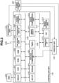
- Fig. 1 illustrates a configuration of an image forming apparatus 100 according to a first exemplary embodiment of the present invention.
- the image forming apparatus 100 includes an operation unit 110, a printer unit 120, a controller unit 140, an inspection unit 150, and a discharge tray 160.
- the image forming apparatus 100 can print an image on a sheet and inspect the obtained printed product.
- the controller unit 140 transmits cyan, magenta, yellow, and black (CMYK) color signals to exposure control units 123C, 123M, 123Y, and 123K, respectively. Then, each of the exposure control units outputs a laser light that corresponds to the color signal it has received.
- CMYK cyan, magenta, yellow, and black
- An intermediate transfer member 126 contacts the photosensitive drums and rotates clockwise in accordance with the rotation of the photosensitive drums.
- a toner image which has been developed is transferred to the intermediate transfer member 126.
- the toner image transferred to the intermediate transfer member 126 is further transferred to a sheet conveyed from a cassette 131 or a cassette 132 by a transfer roller 127.
- a cleaning unit 129 which cleans the toner that remains on the intermediate transfer member 126 after the transfer of the image by the transfer roller 127, is provided at a subsequent stage.
- a density sensor 130 which measures a density of the toner image on the intermediate transfer member 126, is provided in the image forming apparatus.
- the sheet onto which the toner image is transferred is conveyed to a fixing portion 128.
- the toner image is fixed by a built-in heater and a pressure roller.
- the sheet that passed through the fixing portion 128 is temporarily conveyed from a path 133 to a path 134 by a flapper (not shown). After the trailing edge of the sheet passes the path 133, the sheet is switch-backed and conveyed to a path 135 and to a discharge roller 137. In this manner, the sheet is discharged from the printer unit 120 by the rotation of the discharge roller 137. The image-transferred side of the sheet is face down when it is discharged.
- the sheet is conveyed from the fixing portion 128 to the path 133 and to the path 134. Then, immediately after the trailing edge of the sheet passes the path 133, the sheet is switch-backed and conveyed to a two-sided conveying path 136 by a flapper (not shown). Subsequently, a toner image is transferred again to the sheet conveyed to the two-sided conveying path 136 by the transfer roller 127. This toner image is also fixed to the sheet at the fixing portion 128.
- the sheet discharged from the discharge roller 137 is conveyed to the inspection unit 150.
- a reading unit 151 and a reading unit 152 read the image printed on the sheet and generate image data.
- the inspection unit 150 includes a sheet detection unit 154 which detects the sheet. The inspection unit 150 controls the reading timing of the image printed on the sheet according to the timing the sheet detection unit 154 has detected the sheet.
- the image data which has been read is transmitted to an inspection control unit 153 (described below in detail with reference to Fig. 3 ).
- Various types of inspection processing are performed at the inspection control unit 153. If the sheet passes the inspection, the sheet is discharged on the discharge tray 160. If the sheet does not pass the inspection, the sheet is discharged on a NG tray 155.
- Fig. 2 illustrates an inner configuration of the controller unit 140.
- a central processing unit (CPU) 201 performs overall control of the controller unit 140.
- the CPU 201 reads out a control program stored in a read-only memory (ROM) 202 or a hard disk drive (HDD) 220 and controls the controller unit 140.
- the ROM 202 stores programs used by the CPU 201.
- a random access memory (RAM) 203 is used as a main memory and a temporary storage area such as a work area of the CPU 201.
- a non-volatile RAM (NVRAM) 204 stores control parameters.
- a network unit 205 performs communication control. For example, the network unit 205 controls transmission/reception of electronic mails and input/output of page description language (PDL) data with a host apparatus (described below with reference to Fig. 13 ) via a local area network (LAN) .
- the HDD 220 stores programs used by the CPU 201 as is the case with the ROM 202.
- An operation unit I/F 206 is an interface used for the communication between the controller unit 140 and the operation unit 110.
- a printer communication I/F 207 is an interface used for the communication between the controller unit 140 and the printer unit 120.
- a power control I/F 208 is an interface used for the communication between the controller unit 140 and a power control unit 230.
- An ACC I/F 216 is an interface used for the communication between the controller unit 140 and the inspection unit 150.
- a HDD I/F 217 is an interface used for the communication between the controller unit 140 and the HDD 220.
- a timer 209 is used for keeping the current time and monitoring whether the time which has been set has elapsed.
- Each of the above-described units communicates with one another via a system bus 218.
- An image Bus I/F 210 connects an image bus 211 which transfers image signals and the system bus 218.
- An image compression unit 212, an image rotation unit 213, a raster image processor (RIP) unit 214, and a printer I/F 215 are connected to the image bus 211.
- RIP raster image processor
- the image compression unit 212 performs compression/decompression processing of image data in, for example, Joint Photographic Experts Group (JPEG) format.
- the image rotation unit 213 rotates the image data.
- the RIP unit 214 rasterizes the PDL data.
- the printer I/F 215 corrects the image data to be output and printed on a sheet. For example, the printer I/F 215 performs resolution conversion and transmits the print data to the printer unit 120.
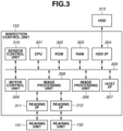
- Fig. 3 illustrates an inner configuration of the inspection control unit 153 in the inspection unit 150.
- a CPU 301 performs overall control of the inspection unit 150.
- the CPU 301 read outs a control program stored in a ROM 302 or a HDD 313 and controls the inspection unit 150.
- Programs used for the operation performed by the CPU 301 are stored in the ROM 302. Further, image data which is printed on a sheet by the printer unit 120 is stored in the ROM 302.
- a RAM 303 is used as a main memory and a temporary storage area such as a work area of the CPU 301.
- a program used by the CPU 301 and image data printed on a sheet by the printer unit 120 are stored in the HDD 313 as is the case with the ROM 302.
- a HDD I/F 304 is used for the communication between the inspection control unit 153 and the HDD 313.
- a reading I/F 311 performs communication between the inspection control unit 153 and the reading unit 151.
- a reading I/F 312 performs communication between the inspection control unit 153 and the reading unit 152.
- the reading I/F 311 controls the reading unit 151 and receives image data read by the reading unit 151.
- the reading I/F 312 controls the reading unit 152 and receives image data obtained read by the reading unit 152.
- the reading unit 151 reads the front side of the sheet and the reading unit 152 reads the back side of the sheet.
- Each of the reading unit 151 and the reading unit 152 includes a sensor array. The sensor arrays are arranged in such a manner that images on the entire area of the conveyed sheet can be read by the sensor arrays.
- a read image processing unit 308 performs processing such as variable magnification processing and gamma correction processing on the image data sent from the reading units 151 and 152, and transmits the processed data to the RAM 303.
- a motor control unit 309 controls various motors in the inspection unit 150.
- a sensor control unit 310 detects the state of the various sensors in the inspection unit 150 and notifies the CPU 301 of the detection result.
- a HOST I/F 307 is used for communication between the inspection control unit 153 and the ACC I/F 216 of the controller unit 140. The HOST I/F 307 performs transmission/reception of print setting and image data.
- An image processing unit 306 executes inspection processing of a printed product by comparing the image data (image data for printing) stored in the ROM 302 or the HDD 313 and the image data obtained by the reading of the reading unit 151 or the reading unit 152.
- Each of the above-described units communicates with one another via a system bus 305.
- three types of inspection processing which are print misregistration inspection, color inspection, and character inspection, are executable.
- the print misregistration inspection is used for inspecting whether there is print misregistration between the front side (first side) and the back side (second side).
- the color inspection is used for inspecting whether the image is printed with an appropriate tint or density.
- the character inspection is used for inspecting whether text information has been correctly printed.
- the inspection processing according to the present embodiment is not limited to the print misregistration inspection, the color inspection, and the character inspection, and the present embodiment can be applied to other inspection processing.
- a distance from a reading start position to a reference point is acquired for both the front side and the back side of the sheet. Then, if the difference between the distance of the front side and the distance of the back side is greater than a predetermined threshold value, it is determined that print misregistration has occurred and the sheet is discharged on the NG tray 155.
- a region is designated as the target of the color inspection.
- a mean value of each RGB color of the designated region of image data read by the reading unit 151 (the reading unit 152 if the side to be inspected is the back side) and the designated region of the image data for printing is calculated.
- a difference between the two mean values is calculated. This difference indicates the color difference. If the color difference is greater than a predetermined threshold value set in advance, it is determined that the image is not printed with the appropriate tint according to the color inspection, and the sheet is discharged on the NG tray 155.
- the above-described determination is made based on the assumption that a color image is printed on a sheet. If inspection of a monochromatic image is to be performed, a mean value of the density of a designated region is obtained in place of the mean value of each RGB color. Then, the difference (density difference) between two mean values is calculated and compared with a threshold value set in advance as the color inspection.
- OCR optical character recognition
- Fig. 13 illustrates a configuration of a host apparatus 1300.
- the host apparatus is, for example, a personal computer (PC) operated by the user.
- PC personal computer
- a CPU 1301 performs overall control of the host apparatus 1300.
- the CPU 1301 reads out a control program stored in a ROM 1302 or a HDD 1304 and controls the host apparatus 1300.
- the ROM 1302 stores programs used by the CPU 1301.
- a RAM 1303 is used as a main memory and a temporary storage area such as a work area of the CPU 1301.
- programs used by the CPU 1301 are stored in the ROM 1302, they are also stored in the HDD 1304.
- a connection I/F 1305 connects the host apparatus 1300 and the LAN.
- the host apparatus 1300 communicates with the image forming apparatus 100 via a network.
- a keyboard 1306 is used for inputting information to the host apparatus 1300.
- Various screens are displayed on a display unit 1307.
- print processing and inspection processing executed by the image forming apparatus 100 can be controlled by the host apparatus 1300.
- a setting screen used for setting the print processing or the inspection processing is displayed on the display unit 1307.
- a print job is transmitted to the image forming apparatus 100 based on the setting made on the setting screen.
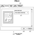
- Fig. 4 illustrates a print setting screen 400 used for making the print setting.
- the print setting screen 400 is displayed on the display unit 1307 when the printer driver, which has been installed in the host apparatus 1300, is executed.
- the user can select printing methods such as "one-sided printing” and "two-sided printing” from a pull-down menu 401 displayed on the print setting screen 400.
- the user determines whether to perform printing on one side or both sides of a sheet. After then, if the user selects an OK key 402, the print setting is made and the job is transmitted to the image forming apparatus 100. On the other hand, if the user selects a cancel key 403, the display of the print setting screen 400 ends.
- an inspection setting screen used for setting the inspection processing of the printed product is displayed. This inspection setting screen will be described in detail below with reference to Fig. 5A .
- Fig. 5A illustrates the inspection setting screen used for setting the inspection processing.
- An inspection setting screen 500 is displayed when the inspection setting tab 404 on the print setting screen 400 is selected by the user.
- the inspection setting screen 500 is displayed on the display unit 1307 when the printer driver, which has been installed in the host apparatus 1300, is executed as is the case with the print setting screen 400.
- three inspection items which are the above-described print misregistration inspection, character inspection, and color inspection, can be set.
- a setting screen used for setting the character inspection setting is displayed. If the user selects a key 504, a setting screen used for setting the color inspection is displayed. Further, if the user desires to perform the print misregistration inspection, the user clicks a check box 501. Additionally, by inputting a permissible value of print misregistration between the front side and the back side of the sheet in a permissible value field 502, an accuracy level of the print misregistration inspection can be set.
- the inspection setting is set. Then, the inspection setting is transmitted to the image forming apparatus 100 together with the print setting as a job. Further, if the user selects a cancel key 506, the display of the inspection setting screen 500 ends.
- the user can respectively make the setting for each inspection item via the inspection setting screen 500.
- the print misregistration inspection is effective only when the two-sided printing is selected, it is useless for a user who performs one-sided printing.
- a screen considering this point is an inspection setting screen 510 illustrated in Fig. 5B .
- the inspection setting screen 510 is displayed when the user selects one-sided printing on the print setting screen 400.
- the difference between the inspection setting screen 500 and the inspection setting screen 510 is that the setting of the print misregistration inspection is disabled on the inspection setting screen 510.
- the setting of the print misregistration inspection on the inspection setting screen 510 is disabled by a strikethrough 511. Thus, the user is unable to make the setting for the print misregistration inspection.
- the inspection setting screen 500 is displayed.
- the method for disabling the setting of the present embodiment is not limited to such a method.
- the inspection item of the print misregistration inspection can be grayed out so that the setting of the print misregistration inspection cannot be set or the inspection item of the print misregistration inspection can be hidden.
- a warning message can be displayed on the inspection setting screen 510 if the user selects the print misregistration inspection.
- the execution of the print misregistration inspection is enabled if the user makes the setting of the print misregistration inspection after confirming the warning message. According to this method, whether an image is printed at the correct position on the sheet when one-sided printing is performed can be determined.
- the present embodiment has been described using one-sided printing and two-sided printing, the present embodiment can be applied to any print setting if printing on both sides or one side of a sheet is determined by the setting.
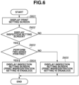
- FIG. 6 illustrates a display control of the print setting screen and the inspection setting screen according to the present embodiment.
- Each step from steps S601 to S605 is processed by the CPU 1301 executing the printer driver installed in the host apparatus 1300.
- step S601 the display unit 1307 of the host apparatus 1300 displays the print setting screen.
- the print setting screen which is displayed is, for example, the print setting screen 400 in Fig. 4 .
- step S602 the CPU 1301 determines whether the inspection setting screen is to be displayed. If the user selects the inspection setting tab 404, the CPU 1301 determines that the inspection setting screen is to be displayed (YES in step S602), and the processing proceeds to step S603. On the other hand, if the user does not select the inspection setting tab 404 and selects the OK key 402 or the cancel key 403, the CPU 1301 determines that the inspection setting screen is not to be displayed (NO in step S602), and the processing ends.
- step S603 the CPU 1301 determines whether the printing is to be performed on both sides of the sheet based on the print setting set on the print setting screen 400. For example, if the user selects two-sided printing on the print setting screen 400, the CPU 1301 determines that the printing is to be performed on both sides of the sheet (YES in step S603), and the processing proceeds to step S604.
- step S604 the display unit 1307 displays the inspection setting screen. The print misregistration inspection setting is enabled on this screen. An example of this inspection setting screen displayed is the inspection setting screen 500 illustrated in Fig. 5A .
Landscapes
- Physics & Mathematics (AREA)
- General Physics & Mathematics (AREA)
- Engineering & Computer Science (AREA)
- Human Computer Interaction (AREA)
- Microelectronics & Electronic Packaging (AREA)
- Accessory Devices And Overall Control Thereof (AREA)
- Facsimiles In General (AREA)
- Control Or Security For Electrophotography (AREA)
- User Interface Of Digital Computer (AREA)
Applications Claiming Priority (3)
| Application Number | Priority Date | Filing Date | Title |
|---|---|---|---|
| JP2011075376A JP5822503B2 (ja) | 2011-03-30 | 2011-03-30 | 検品システム、検品システムの制御方法及びプログラム |
| PCT/JP2012/002095 WO2012132399A1 (en) | 2011-03-30 | 2012-03-27 | Setting apparatus, inspection system, setting method of inspection processing, and program |
| EP12763585.2A EP2691242B1 (de) | 2011-03-30 | 2012-03-27 | Einstellvorrichtung, inspektionssystem, einstellverfahren zur verarbeitung von prüfungen und programm dafür |
Related Parent Applications (2)
| Application Number | Title | Priority Date | Filing Date |
|---|---|---|---|
| EP12763585.2A Division-Into EP2691242B1 (de) | 2011-03-30 | 2012-03-27 | Einstellvorrichtung, inspektionssystem, einstellverfahren zur verarbeitung von prüfungen und programm dafür |
| EP12763585.2A Division EP2691242B1 (de) | 2011-03-30 | 2012-03-27 | Einstellvorrichtung, inspektionssystem, einstellverfahren zur verarbeitung von prüfungen und programm dafür |
Publications (2)
| Publication Number | Publication Date |
|---|---|
| EP4530731A2 true EP4530731A2 (de) | 2025-04-02 |
| EP4530731A3 EP4530731A3 (de) | 2025-06-25 |
Family
ID=46930175
Family Applications (2)
| Application Number | Title | Priority Date | Filing Date |
|---|---|---|---|
| EP12763585.2A Active EP2691242B1 (de) | 2011-03-30 | 2012-03-27 | Einstellvorrichtung, inspektionssystem, einstellverfahren zur verarbeitung von prüfungen und programm dafür |
| EP25151458.4A Pending EP4530731A3 (de) | 2011-03-30 | 2012-03-27 | Einstellvorrichtung, inspektionssystem, einstellverfahren der inspektionsverarbeitung und programm |
Family Applications Before (1)
| Application Number | Title | Priority Date | Filing Date |
|---|---|---|---|
| EP12763585.2A Active EP2691242B1 (de) | 2011-03-30 | 2012-03-27 | Einstellvorrichtung, inspektionssystem, einstellverfahren zur verarbeitung von prüfungen und programm dafür |
Country Status (5)
| Country | Link |
|---|---|
| US (1) | US8879075B2 (de) |
| EP (2) | EP2691242B1 (de) |
| JP (1) | JP5822503B2 (de) |
| CN (1) | CN103459159B (de) |
| WO (1) | WO2012132399A1 (de) |
Families Citing this family (25)
| Publication number | Priority date | Publication date | Assignee | Title |
|---|---|---|---|---|
| JP5822503B2 (ja) | 2011-03-30 | 2015-11-24 | キヤノン株式会社 | 検品システム、検品システムの制御方法及びプログラム |
| JP6287079B2 (ja) * | 2013-11-05 | 2018-03-07 | 富士ゼロックス株式会社 | 検品支援装置、検品支援システム及びプログラム |
| US9199498B2 (en) | 2013-11-21 | 2015-12-01 | Eastman Kodak Company | Inkjet printing method and apparatus with feedback control |
| DE102015203628A1 (de) * | 2014-03-31 | 2015-10-01 | Heidelberger Druckmaschinen Ag | Verfahren zur automatischen Prüfparameterwahl eines Bildinspektionssystems |
| JP6262112B2 (ja) * | 2014-09-29 | 2018-01-17 | 株式会社沖データ | 画像形成装置及び画像形成装置の制御方法 |
| EP3142000A1 (de) * | 2015-09-08 | 2017-03-15 | OCE-Technologies B.V. | Drucksystem mit einer rasterbildprozessoreinheit und verfahren zum drucken mit dem besagten drucksystem |
| JP6672973B2 (ja) * | 2016-04-12 | 2020-03-25 | コニカミノルタ株式会社 | 画像形成システム、画像形成装置、画像形成方法及びプログラム |
| EP3257893B1 (de) | 2016-06-15 | 2018-12-26 | LANXESS Deutschland GmbH | Faser-matrix-halbzeug |
| DE202017003888U1 (de) | 2017-07-21 | 2017-08-10 | Lanxess Deutschland Gmbh | Ölbehälter |
| DE202017003887U1 (de) | 2017-07-21 | 2017-08-17 | Lanxess Deutschland Gmbh | Sitzstrukturen |
| DE202017003886U1 (de) | 2017-07-21 | 2017-08-17 | Lanxess Deutschland Gmbh | Türmodul |
| CN110858132B (zh) * | 2018-11-22 | 2023-07-21 | 安天科技集团股份有限公司 | 一种打印设备的配置安全检测方法及装置 |
| CN111620151B (zh) * | 2019-02-28 | 2021-08-31 | 柯尼卡美能达办公系统研发(无锡)有限公司 | 纸张搬送机构、图像读取装置以及图像形成装置 |
| JP7257232B2 (ja) * | 2019-04-17 | 2023-04-13 | コニカミノルタ株式会社 | 画像検査装置、画像検査方法、画像検査プログラム、および、画像形成システム |
| JP7206164B2 (ja) * | 2019-07-08 | 2023-01-17 | コニカミノルタ株式会社 | 検査装置、画像形成装置、画像形成システム、検査プログラム |
| JP7310409B2 (ja) * | 2019-07-29 | 2023-07-19 | コニカミノルタ株式会社 | 画像形成装置、画像作成方法及び画像作成プログラム |
| JP7433802B2 (ja) | 2019-08-07 | 2024-02-20 | キヤノン株式会社 | 情報処理装置及びその制御方法 |
| JP7466280B2 (ja) * | 2019-09-05 | 2024-04-12 | キヤノン株式会社 | 検品装置とその制御方法、並びにプログラム |
| JP7031688B2 (ja) * | 2020-01-10 | 2022-03-08 | コニカミノルタ株式会社 | 画像検査システム、画像検査設定方法、および画像検査設定プログラム |
| JP7449111B2 (ja) * | 2020-02-18 | 2024-03-13 | キヤノン株式会社 | 検査装置、検査方法 |
| JP7502917B2 (ja) * | 2020-06-30 | 2024-06-19 | キヤノン株式会社 | 検品システム、情報処理装置、その制御方法、及びプログラム |
| JP7825956B2 (ja) | 2021-08-25 | 2026-03-09 | キヤノン株式会社 | 検査装置、検査装置の制御方法、プログラム、及び検査システム |
| JP2023143201A (ja) * | 2022-03-25 | 2023-10-06 | キヤノン株式会社 | 検査システム、検査装置とその制御方法、及びプログラム |
| JP2023172256A (ja) * | 2022-05-23 | 2023-12-06 | 富士フイルムビジネスイノベーション株式会社 | 情報処理装置及びプログラム |
| JP2024123823A (ja) | 2023-03-02 | 2024-09-12 | 富士フイルムビジネスイノベーション株式会社 | 情報処理システム及びプログラム |
Citations (5)
| Publication number | Priority date | Publication date | Assignee | Title |
|---|---|---|---|---|
| JPH05254105A (ja) | 1992-03-11 | 1993-10-05 | Dainippon Printing Co Ltd | 見当マーク検査装置 |
| JPH06160298A (ja) | 1992-11-24 | 1994-06-07 | Nippon Telegr & Teleph Corp <Ntt> | 自動色調判定方法 |
| JPH1139492A (ja) | 1997-07-24 | 1999-02-12 | Dainippon Printing Co Ltd | 印刷物検査装置 |
| JP2011075376A (ja) | 2009-09-30 | 2011-04-14 | Shimadzu Corp | 発光分析装置 |
| EP2691242A1 (de) | 2011-03-30 | 2014-02-05 | Canon Kabushiki Kaisha | Einstellvorrichtung, inspektionssystem, einstellverfahren zur verarbeitung von prüfungen und programm dafür |
Family Cites Families (17)
| Publication number | Priority date | Publication date | Assignee | Title |
|---|---|---|---|---|
| JP3619217B2 (ja) * | 2002-07-19 | 2005-02-09 | キヤノン株式会社 | 検品装置及び画像形成装置 |
| US20040061884A1 (en) * | 2002-09-30 | 2004-04-01 | Fuji Photo Film Co., Ltd. | Printer, method for controlling quality of printing density in printer and system therefor |
| JP4472260B2 (ja) * | 2003-02-07 | 2010-06-02 | 日本ボールドウィン株式会社 | 印刷面検査方法 |
| JP4470500B2 (ja) * | 2004-01-22 | 2010-06-02 | 富士ゼロックス株式会社 | 印刷物検査装置、印刷物検査方法、画像形成装置 |
| JP4834387B2 (ja) * | 2005-11-28 | 2011-12-14 | キヤノン株式会社 | 画像形成装置及び画像形成方法 |
| US20070139703A1 (en) * | 2005-12-19 | 2007-06-21 | Glory Ltd. | Print inspecting apparatus |
| JP4646801B2 (ja) * | 2005-12-27 | 2011-03-09 | キヤノン株式会社 | 画像品質の評価方法およびその装置 |
| JP4259561B2 (ja) * | 2006-09-29 | 2009-04-30 | ブラザー工業株式会社 | 印刷制御装置及びプログラム |
| JP4259559B2 (ja) * | 2006-09-29 | 2009-04-30 | ブラザー工業株式会社 | 印刷システム及び印刷装置 |
| JP2008260193A (ja) * | 2007-04-11 | 2008-10-30 | Komori Corp | 印刷物の色間見当誤差量検出方法および装置 |
| JP4948369B2 (ja) * | 2007-11-16 | 2012-06-06 | キヤノン株式会社 | 情報処理装置及び印刷制御方法 |
| JP5178444B2 (ja) * | 2008-10-16 | 2013-04-10 | キヤノン株式会社 | 画像形成装置、画像形成システム、画像検査方法、及びプログラム |
| JP2011037177A (ja) * | 2009-08-13 | 2011-02-24 | Fuji Xerox Co Ltd | 画像形成装置及びプログラム |
| JP5640685B2 (ja) * | 2009-12-14 | 2014-12-17 | 株式会社リコー | 画像出力検査システム、画像検査装置およびプログラム |
| JP2012025064A (ja) * | 2010-07-26 | 2012-02-09 | Canon Inc | 印刷装置、印刷装置の制御方法、及び、プログラム |
| JP5971034B2 (ja) * | 2011-10-13 | 2016-08-17 | 株式会社リコー | 画像検査装置、画像形成装置、画像検査方法およびプログラム |
| JP6046921B2 (ja) * | 2012-06-05 | 2016-12-21 | キヤノン株式会社 | 検査システム及びその制御方法、並びにプログラム |
-
2011
- 2011-03-30 JP JP2011075376A patent/JP5822503B2/ja active Active
-
2012
- 2012-03-27 EP EP12763585.2A patent/EP2691242B1/de active Active
- 2012-03-27 CN CN201280016665.0A patent/CN103459159B/zh active Active
- 2012-03-27 EP EP25151458.4A patent/EP4530731A3/de active Pending
- 2012-03-27 US US13/519,847 patent/US8879075B2/en active Active
- 2012-03-27 WO PCT/JP2012/002095 patent/WO2012132399A1/en not_active Ceased
Patent Citations (5)
| Publication number | Priority date | Publication date | Assignee | Title |
|---|---|---|---|---|
| JPH05254105A (ja) | 1992-03-11 | 1993-10-05 | Dainippon Printing Co Ltd | 見当マーク検査装置 |
| JPH06160298A (ja) | 1992-11-24 | 1994-06-07 | Nippon Telegr & Teleph Corp <Ntt> | 自動色調判定方法 |
| JPH1139492A (ja) | 1997-07-24 | 1999-02-12 | Dainippon Printing Co Ltd | 印刷物検査装置 |
| JP2011075376A (ja) | 2009-09-30 | 2011-04-14 | Shimadzu Corp | 発光分析装置 |
| EP2691242A1 (de) | 2011-03-30 | 2014-02-05 | Canon Kabushiki Kaisha | Einstellvorrichtung, inspektionssystem, einstellverfahren zur verarbeitung von prüfungen und programm dafür |
Also Published As
| Publication number | Publication date |
|---|---|
| US20130016382A1 (en) | 2013-01-17 |
| EP2691242B1 (de) | 2025-02-19 |
| US8879075B2 (en) | 2014-11-04 |
| EP2691242A4 (de) | 2015-02-25 |
| CN103459159A (zh) | 2013-12-18 |
| EP2691242A1 (de) | 2014-02-05 |
| RU2013148114A (ru) | 2015-05-10 |
| WO2012132399A1 (en) | 2012-10-04 |
| EP4530731A3 (de) | 2025-06-25 |
| CN103459159B (zh) | 2016-05-04 |
| JP5822503B2 (ja) | 2015-11-24 |
| JP2012206461A (ja) | 2012-10-25 |
Similar Documents
| Publication | Publication Date | Title |
|---|---|---|
| EP2691242B1 (de) | Einstellvorrichtung, inspektionssystem, einstellverfahren zur verarbeitung von prüfungen und programm dafür | |
| US10921740B2 (en) | Image forming apparatus, method of controlling the same, and storage medium that select, from among a plurality of paper feed sources, one that satisfies a selected condition | |
| US20120200886A1 (en) | Image forming system | |
| US8705119B2 (en) | Applications, systems and methods for identifying and monitoring critical colors in customer print jobs | |
| JP7501734B2 (ja) | 画像形成装置、画像作成プログラムおよび画像作成方法 | |
| US11415920B2 (en) | Image forming apparatus | |
| JP2013103407A (ja) | 印刷装置、印刷装置の制御方法、及びプログラム | |
| US20100328698A1 (en) | Job processing apparatus that realizes notification appropriate to intention of user and usage environment, control method for the job processing apparatus, and storage medium | |
| JP7698673B2 (ja) | 検査装置及び検査システム | |
| US20160316082A1 (en) | Image forming apparatus and information processing apparatus | |
| JP5896768B2 (ja) | 画像形成装置、その制御方法、及びプログラム | |
| JP6516224B2 (ja) | 画像処理装置、画像処理方法、及びプログラム | |
| RU2574853C2 (ru) | Устройство задания настроек, система контроля, способ задания настроек обработки контроля и программа | |
| CN102289167B (zh) | 图像形成装置及其控制方法 | |
| JP4605540B2 (ja) | 出力システム、管理装置、出力装置及び出力システムの管理方法 | |
| US20260037192A1 (en) | Inspection system | |
| US20250350688A1 (en) | Information processing apparatus, information processing method, and image forming apparatus | |
| EP4440094B1 (de) | Informationsverarbeitungsvorrichtung, steuerverfahren dafür, programm und bilderzeugungssystem | |
| US20190263111A1 (en) | Image processing system, image processing apparatus, image processing method, and computer readable recording medium storing program | |
| US20250045549A1 (en) | Image forming apparatus | |
| JP5459000B2 (ja) | 画像処理装置及びプログラム | |
| EP4607283A1 (de) | Diagnosevorrichtung, steuerverfahren dafür, speichermedium und bilderzeugungsvorrichtung | |
| US20250189919A1 (en) | Image forming apparatus, control method for image forming apparatus, and storage medium | |
| US20250237985A1 (en) | Diagnostic apparatus, control method for the same, storage medium, and image forming apparatus | |
| JP2024175516A (ja) | 画像形成装置 |
Legal Events
| Date | Code | Title | Description |
|---|---|---|---|
| PUAI | Public reference made under article 153(3) epc to a published international application that has entered the european phase |
Free format text: ORIGINAL CODE: 0009012 |
|
| STAA | Information on the status of an ep patent application or granted ep patent |
Free format text: STATUS: THE APPLICATION HAS BEEN PUBLISHED |
|
| AC | Divisional application: reference to earlier application |
Ref document number: 2691242 Country of ref document: EP Kind code of ref document: P |
|
| AK | Designated contracting states |
Kind code of ref document: A2 Designated state(s): AL AT BE BG CH CY CZ DE DK EE ES FI FR GB GR HR HU IE IS IT LI LT LU LV MC MK MT NL NO PL PT RO RS SE SI SK SM TR |
|
| REG | Reference to a national code |
Ref country code: DE Ref legal event code: R079 Free format text: PREVIOUS MAIN CLASS: G03G0015000000 Ipc: B41J0029460000 |
|
| PUAL | Search report despatched |
Free format text: ORIGINAL CODE: 0009013 |
|
| AK | Designated contracting states |
Kind code of ref document: A3 Designated state(s): AL AT BE BG CH CY CZ DE DK EE ES FI FR GB GR HR HU IE IS IT LI LT LU LV MC MK MT NL NO PL PT RO RS SE SI SK SM TR |
|
| RIC1 | Information provided on ipc code assigned before grant |
Ipc: G03G 15/00 20060101ALI20250520BHEP Ipc: G03G 15/01 20060101ALI20250520BHEP Ipc: G06F 3/12 20060101ALI20250520BHEP Ipc: B41J 29/42 20060101ALI20250520BHEP Ipc: B41J 29/38 20060101ALI20250520BHEP Ipc: B41J 29/46 20060101AFI20250520BHEP |
|
| STAA | Information on the status of an ep patent application or granted ep patent |
Free format text: STATUS: REQUEST FOR EXAMINATION WAS MADE |
|
| 17P | Request for examination filed |
Effective date: 20260102 |