EP4461881A2 - Vakuumvorrichtung für hydroaushub - Google Patents
Vakuumvorrichtung für hydroaushub Download PDFInfo
- Publication number
- EP4461881A2 EP4461881A2 EP24202043.6A EP24202043A EP4461881A2 EP 4461881 A2 EP4461881 A2 EP 4461881A2 EP 24202043 A EP24202043 A EP 24202043A EP 4461881 A2 EP4461881 A2 EP 4461881A2
- Authority
- EP
- European Patent Office
- Prior art keywords
- vessel
- water
- excavation
- fluid
- clause
- Prior art date
- Legal status (The legal status is an assumption and is not a legal conclusion. Google has not performed a legal analysis and makes no representation as to the accuracy of the status listed.)
- Pending
Links
Images


Classifications
-
- E—FIXED CONSTRUCTIONS
- E02—HYDRAULIC ENGINEERING; FOUNDATIONS; SOIL SHIFTING
- E02F—DREDGING; SOIL-SHIFTING
- E02F5/00—Dredgers or soil-shifting machines for special purposes
- E02F5/22—Dredgers or soil-shifting machines for special purposes for making embankments; for back-filling
- E02F5/223—Dredgers or soil-shifting machines for special purposes for making embankments; for back-filling for back-filling
- E02F5/226—Dredgers or soil-shifting machines for special purposes for making embankments; for back-filling for back-filling with means for processing the soil, e.g. screening belts, separators; Padding machines
-
- B—PERFORMING OPERATIONS; TRANSPORTING
- B01—PHYSICAL OR CHEMICAL PROCESSES OR APPARATUS IN GENERAL
- B01D—SEPARATION
- B01D33/00—Filters with filtering elements which move during the filtering operation
- B01D33/01—Filters with filtering elements which move during the filtering operation with translationally moving filtering elements, e.g. pistons
- B01D33/03—Filters with filtering elements which move during the filtering operation with translationally moving filtering elements, e.g. pistons with vibrating filter elements
- B01D33/0346—Filters with filtering elements which move during the filtering operation with translationally moving filtering elements, e.g. pistons with vibrating filter elements with flat filtering elements
- B01D33/0353—Filters with filtering elements which move during the filtering operation with translationally moving filtering elements, e.g. pistons with vibrating filter elements with flat filtering elements self-supporting
-
- B—PERFORMING OPERATIONS; TRANSPORTING
- B01—PHYSICAL OR CHEMICAL PROCESSES OR APPARATUS IN GENERAL
- B01D—SEPARATION
- B01D33/00—Filters with filtering elements which move during the filtering operation
- B01D33/80—Accessories
- B01D33/804—Accessories integrally combined with devices for controlling the filtration
-
- B—PERFORMING OPERATIONS; TRANSPORTING
- B04—CENTRIFUGAL APPARATUS OR MACHINES FOR CARRYING-OUT PHYSICAL OR CHEMICAL PROCESSES
- B04C—APPARATUS USING FREE VORTEX FLOW, e.g. CYCLONES
- B04C5/00—Apparatus in which the axial direction of the vortex is reversed
- B04C5/14—Construction of the underflow ducting; Apex constructions; Discharge arrangements ; discharge through sidewall provided with a few slits or perforations
-
- B—PERFORMING OPERATIONS; TRANSPORTING
- B04—CENTRIFUGAL APPARATUS OR MACHINES FOR CARRYING-OUT PHYSICAL OR CHEMICAL PROCESSES
- B04C—APPARATUS USING FREE VORTEX FLOW, e.g. CYCLONES
- B04C5/00—Apparatus in which the axial direction of the vortex is reversed
- B04C5/24—Multiple arrangement thereof
- B04C5/28—Multiple arrangement thereof for parallel flow
-
- B—PERFORMING OPERATIONS; TRANSPORTING
- B04—CENTRIFUGAL APPARATUS OR MACHINES FOR CARRYING-OUT PHYSICAL OR CHEMICAL PROCESSES
- B04C—APPARATUS USING FREE VORTEX FLOW, e.g. CYCLONES
- B04C9/00—Combinations with other devices, e.g. fans, expansion chambers, diffusors, water locks
-
- E—FIXED CONSTRUCTIONS
- E02—HYDRAULIC ENGINEERING; FOUNDATIONS; SOIL SHIFTING
- E02F—DREDGING; SOIL-SHIFTING
- E02F3/00—Dredgers; Soil-shifting machines
- E02F3/04—Dredgers; Soil-shifting machines mechanically-driven
- E02F3/88—Dredgers; Soil-shifting machines mechanically-driven with arrangements acting by a sucking or forcing effect, e.g. suction dredgers
- E02F3/8816—Mobile land installations
-
- E—FIXED CONSTRUCTIONS
- E02—HYDRAULIC ENGINEERING; FOUNDATIONS; SOIL SHIFTING
- E02F—DREDGING; SOIL-SHIFTING
- E02F3/00—Dredgers; Soil-shifting machines
- E02F3/04—Dredgers; Soil-shifting machines mechanically-driven
- E02F3/88—Dredgers; Soil-shifting machines mechanically-driven with arrangements acting by a sucking or forcing effect, e.g. suction dredgers
- E02F3/8891—Dredgers; Soil-shifting machines mechanically-driven with arrangements acting by a sucking or forcing effect, e.g. suction dredgers wherein at least a part of the soil-shifting equipment is handheld
-
- E—FIXED CONSTRUCTIONS
- E02—HYDRAULIC ENGINEERING; FOUNDATIONS; SOIL SHIFTING
- E02F—DREDGING; SOIL-SHIFTING
- E02F3/00—Dredgers; Soil-shifting machines
- E02F3/04—Dredgers; Soil-shifting machines mechanically-driven
- E02F3/88—Dredgers; Soil-shifting machines mechanically-driven with arrangements acting by a sucking or forcing effect, e.g. suction dredgers
- E02F3/90—Component parts, e.g. arrangement or adaptation of pumps
- E02F3/907—Measuring or control devices, e.g. control units, detection means or sensors
-
- E—FIXED CONSTRUCTIONS
- E02—HYDRAULIC ENGINEERING; FOUNDATIONS; SOIL SHIFTING
- E02F—DREDGING; SOIL-SHIFTING
- E02F3/00—Dredgers; Soil-shifting machines
- E02F3/04—Dredgers; Soil-shifting machines mechanically-driven
- E02F3/88—Dredgers; Soil-shifting machines mechanically-driven with arrangements acting by a sucking or forcing effect, e.g. suction dredgers
- E02F3/90—Component parts, e.g. arrangement or adaptation of pumps
- E02F3/92—Digging elements, e.g. suction heads
- E02F3/9206—Digging devices using blowing effect only, like jets or propellers
-
- E—FIXED CONSTRUCTIONS
- E02—HYDRAULIC ENGINEERING; FOUNDATIONS; SOIL SHIFTING
- E02F—DREDGING; SOIL-SHIFTING
- E02F3/00—Dredgers; Soil-shifting machines
- E02F3/04—Dredgers; Soil-shifting machines mechanically-driven
- E02F3/88—Dredgers; Soil-shifting machines mechanically-driven with arrangements acting by a sucking or forcing effect, e.g. suction dredgers
- E02F3/90—Component parts, e.g. arrangement or adaptation of pumps
- E02F3/92—Digging elements, e.g. suction heads
- E02F3/9243—Passive suction heads with no mechanical cutting means
- E02F3/925—Passive suction heads with no mechanical cutting means with jets
-
- E—FIXED CONSTRUCTIONS
- E02—HYDRAULIC ENGINEERING; FOUNDATIONS; SOIL SHIFTING
- E02F—DREDGING; SOIL-SHIFTING
- E02F3/00—Dredgers; Soil-shifting machines
- E02F3/04—Dredgers; Soil-shifting machines mechanically-driven
- E02F3/88—Dredgers; Soil-shifting machines mechanically-driven with arrangements acting by a sucking or forcing effect, e.g. suction dredgers
- E02F3/90—Component parts, e.g. arrangement or adaptation of pumps
- E02F3/92—Digging elements, e.g. suction heads
- E02F3/9256—Active suction heads; Suction heads with cutting elements, i.e. the cutting elements are mounted within the housing of the suction head
- E02F3/9262—Active suction heads; Suction heads with cutting elements, i.e. the cutting elements are mounted within the housing of the suction head with jets
-
- E—FIXED CONSTRUCTIONS
- E02—HYDRAULIC ENGINEERING; FOUNDATIONS; SOIL SHIFTING
- E02F—DREDGING; SOIL-SHIFTING
- E02F3/00—Dredgers; Soil-shifting machines
- E02F3/04—Dredgers; Soil-shifting machines mechanically-driven
- E02F3/88—Dredgers; Soil-shifting machines mechanically-driven with arrangements acting by a sucking or forcing effect, e.g. suction dredgers
- E02F3/90—Component parts, e.g. arrangement or adaptation of pumps
- E02F3/92—Digging elements, e.g. suction heads
- E02F3/9256—Active suction heads; Suction heads with cutting elements, i.e. the cutting elements are mounted within the housing of the suction head
- E02F3/9268—Active suction heads; Suction heads with cutting elements, i.e. the cutting elements are mounted within the housing of the suction head with rotating cutting elements
- E02F3/9275—Active suction heads; Suction heads with cutting elements, i.e. the cutting elements are mounted within the housing of the suction head with rotating cutting elements with axis of rotation parallel to longitudinal axis of the suction pipe
-
- E—FIXED CONSTRUCTIONS
- E02—HYDRAULIC ENGINEERING; FOUNDATIONS; SOIL SHIFTING
- E02F—DREDGING; SOIL-SHIFTING
- E02F3/00—Dredgers; Soil-shifting machines
- E02F3/04—Dredgers; Soil-shifting machines mechanically-driven
- E02F3/88—Dredgers; Soil-shifting machines mechanically-driven with arrangements acting by a sucking or forcing effect, e.g. suction dredgers
- E02F3/90—Component parts, e.g. arrangement or adaptation of pumps
- E02F3/94—Apparatus for separating stones from the dredged material, i.e. separating or treating dredged material
-
- E—FIXED CONSTRUCTIONS
- E02—HYDRAULIC ENGINEERING; FOUNDATIONS; SOIL SHIFTING
- E02F—DREDGING; SOIL-SHIFTING
- E02F7/00—Equipment for conveying or separating excavated material
- E02F7/06—Delivery chutes or screening plants or mixing plants mounted on dredgers or excavators
-
- F—MECHANICAL ENGINEERING; LIGHTING; HEATING; WEAPONS; BLASTING
- F04—POSITIVE - DISPLACEMENT MACHINES FOR LIQUIDS; PUMPS FOR LIQUIDS OR ELASTIC FLUIDS
- F04B—POSITIVE-DISPLACEMENT MACHINES FOR LIQUIDS; PUMPS
- F04B15/00—Pumps adapted to handle specific fluids, e.g. by selection of specific materials for pumps or pump parts
- F04B15/02—Pumps adapted to handle specific fluids, e.g. by selection of specific materials for pumps or pump parts the fluids being viscous or non-homogeneous
- F04B15/023—Pumps adapted to handle specific fluids, e.g. by selection of specific materials for pumps or pump parts the fluids being viscous or non-homogeneous supply of fluid to the pump by gravity through a hopper, e.g. without intake valve
-
- F—MECHANICAL ENGINEERING; LIGHTING; HEATING; WEAPONS; BLASTING
- F04—POSITIVE - DISPLACEMENT MACHINES FOR LIQUIDS; PUMPS FOR LIQUIDS OR ELASTIC FLUIDS
- F04B—POSITIVE-DISPLACEMENT MACHINES FOR LIQUIDS; PUMPS
- F04B23/00—Pumping installations or systems
- F04B23/02—Pumping installations or systems having reservoirs
-
- F—MECHANICAL ENGINEERING; LIGHTING; HEATING; WEAPONS; BLASTING
- F04—POSITIVE - DISPLACEMENT MACHINES FOR LIQUIDS; PUMPS FOR LIQUIDS OR ELASTIC FLUIDS
- F04B—POSITIVE-DISPLACEMENT MACHINES FOR LIQUIDS; PUMPS
- F04B23/00—Pumping installations or systems
- F04B23/04—Combinations of two or more pumps
-
- F—MECHANICAL ENGINEERING; LIGHTING; HEATING; WEAPONS; BLASTING
- F04—POSITIVE - DISPLACEMENT MACHINES FOR LIQUIDS; PUMPS FOR LIQUIDS OR ELASTIC FLUIDS
- F04B—POSITIVE-DISPLACEMENT MACHINES FOR LIQUIDS; PUMPS
- F04B43/00—Machines, pumps, or pumping installations having flexible working members
- F04B43/12—Machines, pumps, or pumping installations having flexible working members having peristaltic action
- F04B43/1253—Machines, pumps, or pumping installations having flexible working members having peristaltic action by using two or more rollers as squeezing elements, the rollers moving on an arc of a circle during squeezing
-
- B—PERFORMING OPERATIONS; TRANSPORTING
- B01—PHYSICAL OR CHEMICAL PROCESSES OR APPARATUS IN GENERAL
- B01D—SEPARATION
- B01D45/00—Separating dispersed particles from gases or vapours by gravity, inertia, or centrifugal forces
- B01D45/12—Separating dispersed particles from gases or vapours by gravity, inertia, or centrifugal forces by centrifugal forces
- B01D45/16—Separating dispersed particles from gases or vapours by gravity, inertia, or centrifugal forces by centrifugal forces generated by the winding course of the gas stream, the centrifugal forces being generated solely or partly by mechanical means, e.g. fixed swirl vanes
-
- B—PERFORMING OPERATIONS; TRANSPORTING
- B04—CENTRIFUGAL APPARATUS OR MACHINES FOR CARRYING-OUT PHYSICAL OR CHEMICAL PROCESSES
- B04C—APPARATUS USING FREE VORTEX FLOW, e.g. CYCLONES
- B04C9/00—Combinations with other devices, e.g. fans, expansion chambers, diffusors, water locks
- B04C2009/005—Combinations with other devices, e.g. fans, expansion chambers, diffusors, water locks with external rotors, e.g. impeller, ventilator, fan, blower, pump
-
- B—PERFORMING OPERATIONS; TRANSPORTING
- B04—CENTRIFUGAL APPARATUS OR MACHINES FOR CARRYING-OUT PHYSICAL OR CHEMICAL PROCESSES
- B04C—APPARATUS USING FREE VORTEX FLOW, e.g. CYCLONES
- B04C5/00—Apparatus in which the axial direction of the vortex is reversed
- B04C5/24—Multiple arrangement thereof
- B04C5/26—Multiple arrangement thereof for series flow
-
- B—PERFORMING OPERATIONS; TRANSPORTING
- B07—SEPARATING SOLIDS FROM SOLIDS; SORTING
- B07B—SEPARATING SOLIDS FROM SOLIDS BY SIEVING, SCREENING, SIFTING OR BY USING GAS CURRENTS; SEPARATING BY OTHER DRY METHODS APPLICABLE TO BULK MATERIAL, e.g. LOOSE ARTICLES FIT TO BE HANDLED LIKE BULK MATERIAL
- B07B1/00—Sieving, screening, sifting, or sorting solid materials using networks, gratings, grids, or the like
- B07B1/28—Moving screens not otherwise provided for, e.g. swinging, reciprocating, rocking, tilting or wobbling screens
- B07B1/30—Moving screens not otherwise provided for, e.g. swinging, reciprocating, rocking, tilting or wobbling screens jigging or moving to-and-fro within their own plane in or approximately in or transverse to the direction of conveyance
-
- E—FIXED CONSTRUCTIONS
- E02—HYDRAULIC ENGINEERING; FOUNDATIONS; SOIL SHIFTING
- E02F—DREDGING; SOIL-SHIFTING
- E02F9/00—Component parts of dredgers or soil-shifting machines, not restricted to one of the kinds covered by groups E02F3/00 - E02F7/00
- E02F9/14—Booms only for booms with cable suspension arrangements; Cable suspensions
Definitions
- the field of the disclosure relates to hydro excavation vacuum apparatus and, in particular, mobile excavating apparatus that process spoil material onboard by separating water from the cut earthen material.
- Hydro vacuum excavation involves directing high pressure water at an excavation site while removing cut earthen material and water by a vacuum system.
- Sites may be excavated to locate utilities or to cut trenches.
- the spoil material is removed by entraining the spoil material in an airstream generated by the vacuum system.
- the spoil material is stored on a vehicle for transport for later disposal of the spoil material.
- Spoil material is conventionally landfilled or dumped at a designated disposal site. Landfill disposal of spoil material containing a large amount of water may be relatively expensive. Further, tightening regulations may limit disposal options for such slurries.
- the apparatus includes a wand for directing pressurized water toward earthen material to cut the earthen material.
- the wand includes a rotary nozzle for directing water in a rotating, circular path toward the earthen material at an excavation site.
- the apparatus includes a vacuum system for removing cut earthen material and water from the excavation site in an airstream.
- the apparatus includes a separation vessel for removing cut earthen material and water from the airstream.
- An airlock receives material from the separation vessel and discharges the material through an airlock outlet.
- the apparatus includes a dewatering system for separating water from cut earthen material discharged from the airlock outlet.
- the dewatering system includes a pre-screen that receives material from the outlet of the airlock.
- the pre-screen has openings for separating material from the separation vessel by size.
- the dewatering system includes a vibratory screen for separating material that passes through the pre-screen by size.
- the vibratory screen has openings sized smaller than the openings of the pre-screen.
- the apparatus includes a wand for directing pressurized water toward earthen material at an excavation site to cut the earthen material.
- the apparatus includes a vacuum system for removing cut earthen material and water from the excavation site in an airstream.
- the vacuum is capable of generating a vacuum of at least 18" Hg at 3000 cubic feet per minute.
- the apparatus includes a separation vessel for removing cut earthen material and water from the airstream.
- An airlock receives material discharged from the separation vessel and discharges the material through an airlock outlet.
- the apparatus includes a dewatering system for separating water from cut earthen material discharged from the airlock outlet.
- the dewatering system includes a pre-screen that receives material from the separation vessel.
- the pre-screen has openings for separating material from the separation vessel by size.
- the dewatering system includes a vibratory screen for separating material that passes through the pre-screen by size.
- the vibratory screen has openings with a size smaller than the size of the openings of the pre-screen.
- a ratio of the size of the openings of the pre-screen to the size of the openings of the vibratory screen is at least about 100:1.
- the apparatus includes a vacuum system for removing cut earthen material and water from an excavation site in an airstream.
- the apparatus includes a deceleration system for collecting cut earthen material and water from the airstream.
- the deceleration system includes a deceleration vessel adapted to reduce a velocity of the airstream to allow material to fall from the airstream.
- the deceleration vessel has an inlet and a spoil material outlet disposed below the inlet.
- the deceleration system includes a deflection plate disposed within the deceleration vessel for directing material in the airstream downward toward the spoil material outlet.
- the apparatus includes a dewatering system for separating water from cut earthen material removed from the excavation site.
- the apparatus includes a vacuum system for removing cut earthen material from an excavation site in an airstream.
- the apparatus includes a deceleration system for collecting cut earthen material from the airstream.
- the deceleration system includes a deceleration vessel adapted to reduce a velocity of the airstream to allow material to fall from the airstream.
- the deceleration vessel has a vertical axis and an inlet and a spoil material outlet disposed below the inlet.
- the deceleration system includes a deflection plate disposed within the deceleration vessel for directing material in the airstream downward toward the spoil material outlet.
- the deflection plate has a material-engaging face having a longitudinal plane. The longitudinal plane of the material-engaging face forms an angle with the vertical axis of the vessel.
- the excavation apparatus includes an excavation fluid pump, a separation vessel and a dewatering system.
- the excavation fluid pump is operated to direct pressurized water toward an excavation site.
- the pressurized water cuts earthen material. Cut earthen material and water are removed from the excavation site in an airstream and into the separation vessel. The cut earthen material and water separate from the airstream and fall toward an airlock disposed below the separation vessel.
- the airstream has an average dwell time of less than about 5 seconds in the separation vessel. Material discharged from the airlock outlet is introduced into the dewatering system.
- the dewatering system separates water from cut earthen material removed from the excavation site.
- a hydro excavation vacuum apparatus for excavating earthen material includes a wand for directing pressurized water toward earthen material to cut the earthen material.
- An excavation fluid pump supplies fluid to the wand to cut the earthen material.
- the apparatus includes a vacuum system for removing cut earthen material and water from the excavation site and a dewatering system for separating water from cut earthen material removed from the excavation site.
- the apparatus includes a fluid storage and supply system which receives water from the dewatering system.
- the fluid storage and supply system includes a first vessel in fluid communication with the excavation fluid pump and a first vessel level sensor for sensing the fluid level in the first vessel.
- the fluid storage and supply system includes a second vessel.
- the second vessel is in fluid communication with the dewatering system to receive water discharged from the dewatering system.
- the fluid storage and supply system includes a second vessel level sensor for sensing the fluid level in the second vessel and a second vessel transfer pump for transferring fluid from the second vessel.
- a hydro excavation vacuum apparatus for excavating earthen material includes a wand for directing pressurized water toward earthen material to cut the earthen material.
- An excavation fluid pump supplies fluid to the wand to cut the earthen material.
- the apparatus includes a vacuum system for removing cut earthen material and water from the excavation site.
- the apparatus includes a dewatering system for separating water from cut earthen material removed from the excavation site.
- the apparatus includes a fluid storage and supply system.
- the fluid storage and supply system includes a first vessel in fluid communication with the excavation fluid pump.
- the fluid storage and supply system includes a second vessel.
- the second vessel is in fluid communication with the dewatering system to receive fluid discharged from the dewatering system.
- the fluid storage and supply system includes a third vessel for receiving fluid from the second vessel.
- An aspect of the present disclosure is directed to a method for hydro excavating a site with an excavation apparatus having at least two vessels for supplying and storing excavation fluid.
- Maiden water is provided in a first vessel of the apparatus.
- the maiden water is at an initial level.
- Pressurized maiden water from the first vessel is directed toward an excavation site.
- the pressurized water cuts earthen material. Cut earthen material and first cycle water are removed from the excavation site.
- First cycle water is separated from the cut earthen material.
- the first cycle water is introduced into a second vessel. Additional maiden water is introduced into the first vessel upon the maiden water level in the first vessel being reduced to below the initial level or less.
- the apparatus in another aspect of the present disclosure directed to a hydro excavation vacuum apparatus for excavating earthen material, includes a wand for directing pressurized water toward earthen material to cut the earthen material.
- An excavation fluid pump supplies fluid to the wand to cut the earthen material.
- the apparatus includes a vacuum system for removing cut earthen material and water from the excavation site.
- the apparatus includes a dewatering system for separating water from cut earthen material removed from the excavation site.
- the apparatus includes a fluid storage and supply system which receives water from the dewatering system.
- the fluid storage and supply system includes a first vessel and a second vessel.
- the second vessel is in fluid communication with the dewatering system to receive water discharged from the dewatering system.
- the fluid storage and supply system includes a third vessel and a valving system for switching the source of water directed through the wand from the first vessel to the second vessel.
- Yet a further aspect of the present disclosure is directed to a method for hydro excavating a site with an excavation apparatus having at least two vessels for supplying and storing excavation fluid.
- Maiden pressurized water from a first vessel is directed toward one or more excavation sites.
- the first vessel has a volume.
- the pressurized water cuts earthen material.
- the volume of maiden pressurized water used for excavation is at least the volume of the first vessel.
- Cut earthen material and first cycle water are removed from one more excavation sites.
- First cycle water is separated from the cut earthen material.
- the first cycle water is introduced into a second vessel. Additional maiden pressurized water is directed toward one or more excavation sites after the volume of the maiden pressurized water used for excavation is at least the volume of the first vessel.
- the airlock in another aspect of the present disclosure directed to an airlock for conveying material, includes a plurality of rotatable vanes that form pockets to hold and convey material.
- the vanes rotate from an airlock inlet to an airlock outlet along a conveyance path.
- the airlock includes a housing.
- the housing has a first sidewall, a second sidewall, and an outer annular wall that extends from the first sidewall to the second sidewall.
- the airlock outlet extends through the outer annular wall.
- the airlock outlet tapers outwardly from a vertex toward at least one sidewall.
- pressurized water is directed toward an excavation site.
- the pressurized water cuts earthen material. Cut earthen material and water are removed from the excavation site and into a separation vessel. The cut earthen material and water separate from the airstream and fall toward an airlock disposed below the separation vessel.
- the airlock has rotating vanes that form pockets to receive cut earthen material and water.
- the airlock has less than 10 vanes. The vanes of the airlock are rotated at a speed of less than 10 RPM to move cut earthen material and water from an airlock inlet toward an airlock outlet. Material discharged from the airlock outlet is introduced into a dewatering system. The dewatering system separates water from cut earthen material removed from the excavation site.
- the apparatus includes a wand for directing pressurized water toward earthen material to cut the earthen material.
- the wand includes a rotary nozzle for directing water in a rotating, circular path toward the earthen material at an excavation site.
- the apparatus includes a vacuum pump for removing cut earthen material and water from the excavation site in an airstream.
- the vacuum pump is a positive displacement pump.
- the apparatus includes a separation vessel for removing cut earthen material and water from the airstream.
- An apparatus includes a conduit for conveying water and cut earthen material from the excavation site to the separation vessel.
- the conduit has a diameter D 1 .
- An airlock receives material from the separation vessel and discharges the material through an airlock outlet.
- the airlock includes vanes with pockets disposed between adjacent vanes. The vanes are sized to receive particles with a diameter D 1 or greater.
- An additional aspect of the present disclosure is directed to a hydro excavation vacuum apparatus for excavating earthen material at an excavation site.
- the apparatus has a lateral axis and includes a wand for directing pressurized water toward earthen material to cut the earthen material.
- the apparatus includes a vacuum system for removing cut earthen material and water from the excavation site in an airstream.
- the apparatus includes a separation vessel for removing cut earthen material and water from the airstream.
- An airlock receives material from the separation vessel and discharges the material through an airlock outlet.
- the apparatus includes a dewatering system for separating water from cut earthen material.
- the dewatering system includes at least one screen for separating material by size.
- the apparatus includes an adjustment system for adjusting a pitch or a roll of the screen.
- the adjustment system includes an actuator for adjusting the pitch and/or the roll of the screen and a pivot member for adjusting the pitch or the roll of the screen.
- the pivot member is aligned with the airlock outlet relative to
- An aspect of the present disclosure is directed to a hydro excavation vacuum apparatus for excavating earthen material at an excavation site.
- the apparatus has a longitudinal axis and includes a wand for directing pressurized water toward earthen material to cut the earthen material.
- the apparatus includes vacuum system for removing cut earthen material and water from the excavation site in an airstream.
- the apparatus includes a separation vessel for removing cut earthen material and water from the airstream.
- An airlock receives material from the separation vessel and discharges the material through an airlock outlet.
- the apparatus includes a dewatering system for separating water from cut earthen material.
- the dewatering system includes at least one screen for separating material by size.
- the screen has a rear toward which material is loaded onto the screen from the airlock outlet and a front toward which material is discharged from the screen.
- the screen has a center plane midway between the rear and the front.
- the apparatus incudes an adjustment system for adjusting a pitch or a roll of the screen.
- the adjustment system includes an actuator for adjusting the pitch or the roll of the screen.
- the adjustment system includes a pivot member for adjusting the pitch and/or the roll of the screen. The pivot member is rearward to the center plane of the screen relative to the longitudinal axis.
- the apparatus has a longitudinal axis and includes a wand for directing pressurized water toward earthen material to cut the earthen material.
- the apparatus includes a vacuum system for removing cut earthen material and water from the excavation site in an airstream.
- the apparatus includes a separation vessel for removing cut earthen material and water from the airstream.
- the apparatus includes an airlock that receives material from the separation vessel and discharges the material through an airlock outlet.
- the apparatus includes a dewatering system for separating water from cut earthen material.
- the dewatering system includes at least one screen for separating material by size.
- An adjustment system for adjusting a pitch and a roll of the screen includes an actuator for adjusting the pitch or the roll of the screen.
- the adjustment system includes a pivot member for adjusting the pitch and the roll of the screen.
- the pivot member includes a first portion to adjust the roll of the screen and a second portion to adjust the pitch of the screen.
- Yet a further aspect of the present disclosure is directed to a cyclonic separation system for separating material entrained in an airstream.
- the system includes one or more cyclones for separating material from the airstream.
- the one or more cyclones have a solids outlet.
- the system includes a sealed conveyor with the one or more cyclones discharging material directly into the conveyor through the solids outlet.
- the system includes a discharge pump with the sealed conveyor discharging material into the discharge pump.
- the apparatus includes a wand for directing pressurized water toward earthen material to cut the earthen material.
- An excavation fluid pump supplies fluid to the wand to cut the earthen material.
- the apparatus includes a vacuum system for removing cut earthen material and water from an excavation site and includes a dewatering system for separating water from cut earthen material removed from the excavation site.
- the apparatus includes a fluid storage and supply system that receives water from the dewatering system.
- the fluid storage and supply system includes a discharge manifold for offloading water from the fluid storage and supply system.
- the system includes a first vessel and a second vessel.
- the second vessel is in fluid communication with the dewatering system to receive water discharged from the dewatering system.
- the system includes a transfer pipe for transferring fluid from the first vessel to an excavation fluid pump.
- the system includes a valve for selectively directing fluid from the first vessel between (1) the transfer pipe and (2) the discharge manifold.
- the fluid storage and supply system includes a first vessel, a second vessel for receiving water from a dewatering system, a third vessel, and a manifold connected to the first, second and third vessels. Water is added to the first vessel.
- One or valves are actuated such that the first vessel is in fluid communication with the manifold and the third vessel is in fluid communication with the manifold.
- a first vessel transfer pump is operated to transfer water from the first vessel, into the manifold and into the third vessel.
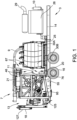
- FIG. 1 An example hydro excavation vacuum apparatus 3 for excavating earthen material is shown in Figure 1 .
- the hydro excavation vacuum apparatus 3 is used to excavate a site by use of a jet of high pressure water expelled through a wand.
- the cut earthen material and water are removed by a vacuum system and are processed onboard the apparatus by separating the cut earthen material from the water. Processed water may suitably be used for additional excavation or disposed.
- Recovered earthen material may be used to backfill the excavation site or disposed.
- the hydro excavation vacuum apparatus 3 may include a chassis 14 which supports the various components (e.g., vacuum system, separation vessel, airlock and/or dewatering system) with wheels 16 connected to the chassis 14 to transport the apparatus 3.
- the apparatus 3 may be self-propelled (e.g., with a dedicated motor that propels the apparatus) or may be adapted to be towed by a separate vehicle (e.g., may include a tongue and/or hitch coupler to connect to the separate vehicle).
- the hydro excavation vacuum apparatus 3 includes a dedicated engine 26 that powers the various components such as the excavation pump, vacuum pump, vibratory screens, conveyors and the like.
- the engine 26 is eliminated and the apparatus is powered by a motor that propels the apparatus or the apparatus 3 is powered by other methods.
- the apparatus 3 includes a front 10, rear 18, and a longitudinal axis A ( Fig. 3A ) that extends through the front 10 and rear 18 of the apparatus 3.
- the apparatus 3 includes a lateral axis B that is perpendicular to the longitudinal axis A.
- the hydro excavation vacuum apparatus 3 includes a wand 4 ( Fig. 3B ) for directing pressurized water W toward earthen material to cut the earthen material.
- the wand 4 is connected to an excavation fluid pump 6 that supplies water to the wand 4.
- the pump 6 may supply a pressure of, for example, at least about 500 psi or at least about 1,000 psi (e.g., from about 1,000 psi to about 5,000 psi or from 1,000 psi to about 3,000 psi).
- the wand 4 includes a rotary nozzle 8 ( Fig. 3C ) for directing water W toward the earthen material to cut the earthen material.
- a rotary nozzle 8 for directing water W toward the earthen material to cut the earthen material.
- any rotary nozzle that causes the water to be directed toward the earthen material in a circular path at the site of the excavation may be used.
- Such rotary nozzles may include a rotor insert with blades that rotate around a longitudinal axis of the nozzle when water is forced through the nozzle.
- the rotor insert may include three or more channels that force fluid to flow in different pathways through the rotor insert to cause the water to move along a circular path as it contacts the excavation material (i.e., the water moves within a cone that extends from the nozzle toward the excavated material).
- a straight tip nozzle that directs fluid along a straight path in a concentrated jet may be used.
- the hydro excavation vacuum apparatus 3 includes a vacuum system 7 ( Fig. 1 ) for removing spoil material from the excavation site.
- Spoil material or simply "spoils” may include, without limitation, rocks, cut earthen material (e.g., small particulate such as sand to larger pieces of earth that are cut loose by the jet of high pressure water), slurry, and water used for excavation.
- the spoil material may have a consistency similar to water, a slurry, or even solid earth or rocks.
- the terms used herein for materials that may be processed by the hydro excavation vacuum apparatus 3 such as, for example, “spoils,” “spoil material,” “cut earthen material” and “water”, should not be considered in a limiting sense unless stated otherwise.
- the vacuum system 7 includes a boom 9 that is capable of rotating toward the excavation site to remove material from the excavation site.
- the boom 9 may include a flexible portion 5 ( Fig. 3B ) that extends downward to the ground to vacuum spoil material from the excavation site.
- the flexible portion 5 may be manipulated by a user to direct the vacuum suction toward the excavation site.
- the vacuum system 7 acts to entrain the cut earth and the water used to excavate the site in a stream of air.
- a blower or vacuum pump 24 ( Fig. 3B ) pulls a vacuum through the boom 9 to entrain the material in the airstream. Air is discharged from the blower 24 after material is removed from the airstream.
- the airstream having water and cut earth entrained therein is pulled through the boom 9 and through a series of conduits (e.g., conduit 47 shown in Figure 6 ) and is pulled into a separation vessel 21, described further below.
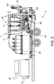
- the separation vessel 21 removes at least a portion of cut earthen material and water from the airstream. Air exits one or more separation vessel air outlets 49 and is introduced into cyclones 11 ( Fig. 2 ) to remove additional spoil material (e.g., water, small solids such as sand, low density particles such as sticks and grass, and the like) not separated in the separation vessel 21. Material that collects in the bottom of the cyclones 11 is conveyed by a cyclone discharge pump 20 ( Fig.
- the air removed from the cyclones 11 is introduced into one or more filter elements before entering the vacuum pump 24.
- the vacuum pump 24 may be disposed in or near the engine compartment 26 ( Fig. 1 ). Air is removed from the apparatus through a vacuum exhaust 29.
- the vacuum pump 24 generates vacuum in the system to pull water and cut earthen material into the apparatus 3 for processing.
- the vacuum pump 24 is a positive displacement pump.
- Such positive displacement pumps may include dual-lobe or tri-lobe impellers (e.g., a screw rotor) that draw air into a vacuum side of the pump and forces air out the pressure side.
- the pump is capable of generating a vacuum of at least 18" Hg and/or a flow rate of at least about 3000 cubic feet per minute.
- the pump may be powered by a motor having a power output of, for example, at least 75 hp, at least 100 hp or even at least 125 hp.
- the separation vessel 21 and cyclones 11 are part of a separation system 46 for removing spoil material from the airstream.
- the separation vessel 21 is a first stage separation in which the bulk of spoil material is removed from the airstream with carryover material in the airstream being removed by the cyclones 11 in a second stage (i.e., the separation vessel 21 is the primary separation vessel with the downstream cyclones 11 being secondary separation vessels).
- Spoil material containing water and cut earth is introduced into the separation vessel 21 through inlet conduit 47 ( Fig. 6 ). At least a portion of spoil material falls from the airstream to a spoil material outlet 33 and into an airlock 55. Air removed through air outlets 49 is processed in cyclones 11 ( Fig. 2 ) to remove at least a portion of carryover spoil material.
- the particle size of spoils entering the cyclones 11 will be smaller than spoil particles removed by the separation vessel 21.
- Spoils removed from the air by the cyclones 11 are typically fluidic. Spoil material removed by the cyclones 11 is fed by the cyclone discharge pump 20 ( Fig. 1 ) to the dewatering system 95 described further below (e.g., directly to a vibratory screen). Air exiting the cyclones 11 passes through a filter element before entering the vacuum pump 24 ( Fig. 3B ). The air is pulled through the vacuum pump 24 and exits the apparatus through the air exhaust 29.
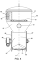
- the separation vessel 21 has an inlet 31 ( Fig. 5 ) and a spoil material outlet 33 disposed below the inlet 31.
- An air outlet 49 ( Fig. 6 ) is disposed above the inlet 31.
- the separation vessel 21 includes a plurality of air outlets 49.
- the separation vessel 21 may include a single air outlet 49.
- the outlets 49 are fluidly connected to the cyclones 11 ( Fig. 2 ) to separate material that remains entrained in the airstream withdrawn from the outlets 49.
- the cyclones 11 may be part of a cyclonic separation system 67 ( Fig. 1 ).
- the cyclonic separation system 67 includes the cyclones 11 and the cyclone discharge pump 20.
- the cyclone discharge pump is a peristaltic pump that is connected to the cyclone discharge 76 by conduits (e.g., hoses or ducts).
- An example peristaltic pump 20 is shown in Figure 35 described further below.
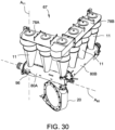
- FIG. 30-34 Another embodiment of the cyclonic separation system 67 is shown in Figures 30-34 .
- the cyclones 11 receive airflow from the separation vessel outlets 49 ( Fig. 4 ) through cyclone inlets 70 ( Fig. 32 ). Cyclonic action in the cyclones 11 causes entrained material to fall to the cyclone solids outlet 76 ( Fig. 31 ). It should be noted that "solids outlet” should not be considered in a limiting sense and any type of material may fall through the solids outlet 76 (e.g., water, mud, sand, sticks, etc.). Air is pulled through the cyclones 11 and is discharged through cyclone discharge manifolds 78A, 78B and is directed to one or more filter elements before entering the vacuum pump 24 ( Fig. 3B ).
- the cyclone solids outlets 76 should be sized to reduce or prevent bridging of granular material that passes through the outlets 76.
- the cyclone solids outlets 76 are fluidly connected to conveyors 80A, 80B (e.g., the outlets 76 are formed in the conveyor housing 98).
- the conveyors 80A, 80B are sealed to reduce or prevent air from entering the vacuum system through the conveyors 80A, 80B (e.g., having gaskets or bearings or the like that seal the conveyor from the ambient atmosphere).
- the conveyors 80A, 80B are screw conveyors (e.g., an auger) having a rotating screw 82A, 82B ( Fig. 31 ).
- the screw conveyor may be a centerless screw conveyor (i.e., lacking a center shaft).
- the screw conveyor may include a center shaft.
- the one or more conveyors 80 may be slat conveyors, belt conveyors or rotary vane conveyors.
- the conveyors 80 are powered by motors 80A, 80B which may be quick-attach motors to facilitate clean-out of the conveyors 80.
- the conveyors 80 include access clamps 96 ( Figs. 30-32 ) that may be opened to allow the motors 86 and screw 82 to be removed the conveyor housing 98 ( Fig. 34 ) as shown in Figure 33 .
- the conveyor screw 82 may be connected to the motor 86 to allow both the motor and screw to be removed from the conveyor housing as a single piece.
- the longitudinal axis A 80 ( Fig. 30 ) of the conveyors 80A, 80B is generally orthogonal to the longitudinal axis A 11 of the cyclones 11.
- the conveyors 80 may be sized and shaped to allow the conveyor to accept surges of material relatively quickly to reduce or prevent bridging of material through cyclone outlets 76.
- the conveyor screw 82 may be off-center with the center of the screw 82 being closer to the bottom of the housing 98 ( Fig. 34 ) (i.e., the screw 82 is undersized compared to the housing 98).
- the cyclonic separation system 67 may generally include any number of cyclones 11 and conveyors 80 (e.g., one conveyor, two conveyors or more and/or at least one cyclone, at least two, at least three, at least four, at least five, at least six or more cyclones 11).
- the cyclonic separation system 67 generally does not include an airlock unless stated otherwise.
- the conveyors 80 convey material toward conveyor outlets 84A, 84B ( Fig. 31 ) where the material is discharged into the cyclone discharge pump 20.
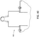
- the cyclone discharge pump 20 is a peristaltic pump.
- the peristaltic pump 20 seals the system 67 by reducing the amount of air that may enter the system 67.
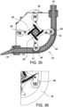
- peristaltic pumps may include a plurality of rollers 88 that rotate about the pump.
- the rollers 88 compress a hose or tube 90 in succession as they rotate to push material through a pump outlet 94.
- the pump 20 includes four rollers 88. In other embodiments, more or less than four rollers 88 may be used.
- the rollers 88 may be configured to retract as shown in Figure 36 (e.g., as when the pump 20 is not in operation). Configuring the rollers 88 to retract while not in operation allows the pump 20 to receive material that is discharged from the cyclones 11 during storage and transportation. Retraction of the rollers 88 also assists in winterization, cleaning, and replacement of the tube 90 and may extend the life of the tube 90.
- the rollers 88 may pivot about a pivot pin 97 to retract with a biasing element 99 (e.g., spring) biasing the rollers in an extended position. Retraction of the rollers 88 may be automated by configuring the pump to reverse to cause the rollers 88 to retract when the pump 20 is switched off.
- a biasing element 99 e.g., spring
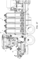
- material may fall by gravity through the pump inlet 93 and into the hose 90. Material discharged from the pump 20 is conveyed to the dewatering system 95 ( Fig. 37 ) through outlet 94.
- the cyclonic separation system 67 may be part of the hydro excavation vacuum apparatus 3 as shown in Figure 37 or may be used in other applications such as in reclaimers (e.g., drill fluid reclaimers).
- the separation vessel 21 includes an upper portion 51 ( Fig. 4 ) having a sidewall 56 and one or more air outlets 49 formed in the sidewall 56.
- the vessel 21 includes a lower portion 57 that tapers to the spoil material outlet 33 ( Fig. 5 ).
- the upper portion 51 and lower portion 57 may be adapted (e.g., shaped), at least in part to ease manufacturing, for fit-up and for minimizing the potential for creating internal surface features where material could set and build-up in the inner surfaces of the separation vessel 21.
- the lower portion 57 is conical.
- the conical lower portion 57 may be arranged (e.g., with a sufficient slope) to reduce potential for cut earthen material to collect on the lower portion 57.
- the illustrated lower portion 57 of the separation vessel 21 has a circular, cross-section to eliminate internal corners where cuttings may set and build-up.
- the lower portion 57 may have a non-circular cross-sectional profile.
- the lower portion 57 may include a generally square profile with relatively large fillets at each corner.
- the upper portion 51 has a circular or generally circular cross-section. The upper portion 51 may be cylindrical to ease the transitioning to the conical lower portion 57.
- the inlet 31 extends through the conical lower portion 57. In other embodiments, the inlet extends through the upper portion 51.
- the vessel 21 has a central vertical axis D ( Fig. 6 ).
- the separation vessel 21 may be sized to reduce the dwell time of material in the vessel.
- the dwell time may be less than 5 seconds, less than 3 seconds or less than 1 second (at standard cubic feet). Dwell time
- the apparatus 3 includes a single separation vessel 21 in the first stage removal of solids and water from the airstream. In other embodiments, two or more separation vessels 21 are operated in parallel in the first stage removal of solids and water from the airstream. In some embodiments, the separation vessel 21 processes from 0.5 ft 3 of spoil material per minute to 2.5 ft 3 of spoil material per minute.
- the separation vessel 21 is a deceleration vessel in which the velocity of the airstream is reduced causing material to fall from the airstream toward a bottom of the separation vessel 21.
- the deceleration vessel 21 may be part of a deceleration system 23 ( Fig. 4 ) for removing material from the airstream by gravity.
- the deceleration vessel 21 is adapted to allow material to fall from the airstream by gravity rather than by vortexing of air within the vessel 21.
- the inlet 31 of the vessel 21 is arranged such that the airstream does not enter the vessel 21 tangentially.
- the inlet conduit 47 (and inlet 31) may have a longitudinal axis E that passes through the central vertical axis D of the deceleration vessel 21.
- the longitudinal axis E is separated a relatively small amount from the central vertical axis D of the deceleration vessel 21 (e.g., by a distance less than 33% of the radius of vessel 21 or a distance less than 25%, 15%, 10% or 5% of the radius of the vessel 21).
- the deceleration vessel 21 may have an effective cross-sectional area (i.e., cross-sectional area of void space) larger than the cross-sectional area of the inlet conduit 47 to reduce the velocity of the airstream in the vessel 21.
- the ratio of the effective cross-sectional area of the deceleration vessel 21 to the effective cross-sectional area of the inlet conduit 47 may be at least about 7.5:1 or, as in other embodiments, at least about 10:1, at least about 15:1 or even at least about 20:1 to reduce the velocity of the airstream to allow material to fall from the airstream.
- the effective cross-sectional area of the deceleration vessel 21 is proportional to the squared radius of the upper portion 51 of the deceleration vessel 21 and the effective cross-sectional area of the inlet conduit 47 is proportional to the squared radius of the inlet conduit 47.
- the ratio of the radius of the deceleration vessel 21 to the radius of the inlet conduit may be at least about 3:1, at least about 4:1, or even at least about 5:1.
- the deceleration system 23 also includes a deflection plate 27 disposed within the deceleration vessel 21.
- the deflection plate 27 is configured and positioned to cause spoil material entrained in the airstream to contact the plate 27 and be directed downward toward the spoil material outlet 33.
- the deflection plate 27 includes a material-engaging face 39 ( Fig. 6 ) configured to contact material entrained in the airstream.
- the face 39 has a longitudinal plane F and the plane F forms an angle ⁇ with the vertical axis D of the vessel 21.
- the angle ⁇ between the longitudinal plane F of the material-engaging face 39 of the deflection plate 27 and the vertical axis D of the vessel 21 may be from about 5° to about 75° or from about 5° to about 60°.
- the longitudinal axis E of the inlet conduit 47 (and inlet 31) may intersect the deflection plate 27.
- the central vertical axis D may intersect the deflection plate 27 or the plate may be forward or rearward to the central vertical axis D (e.g., forward or rearward up to 10% of the radius or forward or rearward up to 25%, 50% or 75% of the radius of the vessel).
- the deflection plate 27 includes a wear plate 41 connected to a support 43 to allow the wear plate 41 to be replaced upon the plate 41 becoming worn.
- the wear plate 41 may be made of an abrasion resistant material including steel (e.g., AR400 abrasion resistant steel) or abrasion resistant plastics.
- a separation vessel 21 using cyclonic separation i.e., a cyclone in which airflow travels in a helical pattern is used to remove material from the airstream.
- FIG. 6 and 8A An example airlock 55 is shown in Figures 6 and 8A .
- the airlock 55 includes a plurality of rotatable vanes 59 connected to a shaft 61.
- the vanes 59 rotate along a conveyance path in the direction shown by arrow R in Figure 6 .
- the shaft 61 is connected to a motor 58 ( Fig. 4 ) that rotates the shaft 61 and vanes 59.
- the airlock 55 has an airlock inlet 69 through which material passes from the deceleration vessel 21 and an airlock outlet 71 through which water and cut earthen material are discharged.
- the airlock 55 includes a housing 63 ( Fig. 8A ) with the vanes 59 rotating within the housing 63.
- the housing 63 includes a first sidewall 85, a second sidewall 87, and an outer annular wall 81 that extends between the first sidewall 85 and the second sidewall 87.
- the vanes 59 include a main portion 75 and an outer wear strip 77 that is connected to the main portion 75 by fasteners 79.
- the outer wear strip 77 extends toward the outer annular wall 81 of the housing 63.
- Material may lodge between the wear strip 77 and the annular wall 81 causing the wear strip to wear.
- the strip 77 wears, it may be adjusted outward (e.g., by use of slots in the strip 77 through which the fasteners 79 extend). Alternatively, the strip 77 may be replaced when it is worn out or no longer functional.
- Air may pass from the ambient environment, through the gaps between the vanes 59 or wear strips 77 and the outer annular wall 81 and into the vacuum system 7 ( Fig. 1 ).
- the vanes 59 contact the outer annular wall 81 (e.g., as with wiper vanes) to more fully seal air from the vacuum system 7.
- the airlock outlet 71 has a vertex 83. Proceeding in the direction of rotation of the vanes 59, the airlock outlet 71 tapers outwardly from the vertex 83 toward at least one sidewall 85, 87. In the illustrated embodiment, the outlet 71 tapers from the vertex 83 toward the first sidewall 85 and tapers from the vertex 83 toward the second sidewall 87 (i.e., proceeding in the direction of rotation of the vanes, the first portion of the outlet 71 is triangular in shape). The outlet 71 may taper toward the sidewalls 85, 87 in a straight path as shown or, as in other embodiments, in a curved path.
- the outer annular wall 81 has a center plane H that is midway between the first and second sidewalls 85, 87.
- the vertex 83 is at the center plane H.
- the vanes 59 may taper to allow a small opening to be exposed to the ambient as the vanes rotate.
- the airlock 55 may also include pocket sidewalls 91 ( Fig. 8A ) that contact and rotate with the vanes 59. In other embodiments, the airlock 55 does not include pocket sidewalls 92.
- the airlock has less than about 15 vanes, less than about 10 vanes or about 8 vanes or less. In some embodiments, the vanes 59 rotate at a speed of less than about 15 RPM or less than about 10 RPM or even less than about 5 RPM.
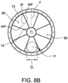
- the number of vanes 59 and the diameter of the airlock 55 are selected in some embodiments so that the pocket 89 may accommodate the largest size of cut earthen material that may travel through the vacuum system 7 to the separation vessel 21.
- the largest material that could reach the airlock is material with a diameter equal to the diameter D1 of the conduits through which air and cut earthen material travel to the separation vessel 21.
- the vanes 59 are sized to receive particles P with a diameter D1 ( Fig. 8B ) or greater.
- the vane pockets 89 may have a depth d of D1 or more.
- the pocket 89 may have width w of D1 or more at a mid-point MP of the pocket, the mid-point MP being midway between a top 72 and bottom 74 of the pocket 89.
- Water and cut earth that exits the airlock 55 through the airlock outlet 71 is introduced into the dewatering system 95 described further below (e.g., may be gravity fed to the dewatering system 95 as shown in the illustrated embodiments).
- the water and cut earthen material is directly introduced into the dewatering system 95 (e.g., directly fed to a screening system without intermediate processing).
- the dewatering system 95 ( Fig. 9 ) of some embodiments includes a pre-screen 101 that first engages material discharged from the outlet 71 of the airlock 55.
- the pre-screen 101 has a plurality of slats 103 with openings formed between slats 103 through which material falls.
- the pre-screen 101 may have relatively large openings (e.g., at least about 0.5 inches, at least about 1 inch, at least about 1.5 inches, or 2 inches or more) such that relatively large material is prevented from passing through the pre-screen 101.
- the slats 103 have ribs 105 which reinforce the slats 103.
- the pre-screen 101 may be adapted to withstand the impact of large stones and earthen material that are capable of being removed by the vacuum system 7 ( Fig. 1 ).
- Example screens include screens that may be referred to by those of skill in the art as a "grizzly screener” or simply “grizzly.”
- the pre-screen 101 may vibrate or, as in other embodiments, does not vibrate.
- the dewatering system 95 of this embodiment includes a vibratory screen 109, more commonly referred to as a "shaker", that separates material that passes through the pre-screen 101 by size.
- the vibratory screen 109 has openings with a size smaller than the size of the openings of the pre-screen 101.
- the size of the openings of the vibratory screen 109 are less than 250 micron, less than about 150 micron or less than about 100 micron.
- the ratio of the size of the openings of the pre-screen 101 to the size of the openings of the vibratory screen 109 may be at least about 100:1, at least about 250:1, or even at least about 500:1.
- the listed size of the openings and ratios thereof are exemplary and other ranges may be used unless stated otherwise.
- the vibratory screen 109 may be part of a shaker assembly 113.
- the shaker assembly 113 includes vibratory motors 117 that cause the screen 109 to vibrate.
- the shaker assembly 113 may be configured to move the vibratory screen 109 linearly or in an elliptical path (e.g., by arranging the number of motors, orientation of the motors, and/or placement of the motors to move the vibratory screen 109 linearly or in an elliptical path).
- the shaker assembly 113 rests on isolators 129 (shown as air bags) to isolate the vibratory movement of the assembly 113 from the chassis or frame to which it is connected.
- the screen 109 is divided into multiple segments that can separately be changed out for maintenance.
- the apparatus 3 does not include a mixer for mixing spoil material (e.g., for mixing solids to promote drying or for mixing in drying agents).
- a mixer for mixing spoil material e.g., for mixing solids to promote drying or for mixing in drying agents.
- Liquid that passes through the vibratory screen 109 collects in a catchpan 112 ( Fig. 14 ) and is conveyed by a return water pump 110 to the fluid storage and supply system 25 described more fully below.
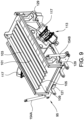
- the dewatering system 95 includes a flat wire belt conveyor 133.
- Such flat wire belt conveyors 133 may include spaced wires or rods which form an open mesh in the belt that allow for liquids and particles that fit through the mesh openings to pass through the mesh.
- the flat wire belt conveyor 133 may remove larger solids and unhydrated soil clumps which helps prevent downstream separation units from blinding (e.g., pluggage of mesh openings) and abrasive wear and damage.
- the mesh size of the belt may be from about 0.25 cm to about 5 cm or from about 0.5 cm to about 3 cm.
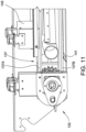
- the flat wire belt conveyor 133 angles upward toward the rear 18 ( Fig. 1 ) of the apparatus 3 to promote separation of water from the cut earthen material. Liquid and small solids that pass through the mesh belt 137 ( Fig. 11 ) fall through the top course 137A of the belt, land on the bottom course 137B of mesh (i.e., the return) and fall through the bottom course of mesh onto a conveyor floor or "chute" 141.
- the belt 137 may rest on the conveyor floor 141 and scrape material toward the liquid discharge end of the flat wire belt conveyor 133. Solids that do not pass through the openings are carried forward by the belt 137.
- the belt 137 is shown of solid, unperforated material in the Figures for simplicity, it should be understood that, in this embodiment, the belt 137 includes mesh openings throughout the top course 137A and bottom course 137B.
- the flat wire belt conveyor 133 may include a series of deflectors 145 that act to turn or otherwise redirect solids that are moving forward on the conveyor 133. By turning the solids, additional fluid may fall through the conveyor 133 and be recovered as effluent.
- the effluent that passes through the flat wire belt conveyor 133 is conveyed down the conveyor floor 141 and falls onto a shaker assembly 159 ( Fig. 10 ) having a vibratory screen 109.
- the shaker assembly 159 may be configured similar to shaker assembly 113 described above and description herein of the shaker assembly 113 should be considered to apply to shaker assembly 159 unless stated otherwise.
- the shaker assembly 159 includes one or more vibratory screens 109 through which liquid and fine solids pass.
- the shaker assembly 159 includes a first side 159A which processes material that passes through and the flat wire belt conveyor 133 and a second side 159B which processes material separated by cyclones 11 ( Fig. 2 ).
- the openings of the flat wire belt conveyor 133 are generally larger than the openings of the shaker assembly 159 such that the second shaker assembly 159 separates finer solids.
- the dewatering system 95 of the present disclosure may include additional separation and/or purification steps for processing cut earthen material.
- the cut earth is separated from water only by use of a (1) a first stage pre-screen or flat wire belt conveyor, and (2) a second stage vibratory screen.
- the screen e.g., pre-screen 101 or flat wire belt conveyor 133
- the screen may receive spoil material directly from the separation vessel 21 without intermediate processing, i.e., without feeding the material to a hydrocyclone such as a desilter cone to separate water from earthen material.
- water that passed through the screens may be fed directly to the water supply and storage system 25 ( Fig. 1 ) described further below without being further processed (e.g., centrifugation).
- the water recovered from the excavation site is not treated without additives (e.g., flocculants and/or coagulants).
- the hydro excavation vacuum apparatus 3 may include an adjustment system 148 ( Fig. 12 ) for adjusting a pitch and a roll of one or more screens of the dewatering system 95.
- the adjustment system 148 may generally be used to adjust any screen such as the pre-screen 101, vibratory screen 109 or flat wire belt conveyor 133 ( Fig. 10 ) or to adjust combinations of these screens.
- the adjustment system 148 includes a pivot member 150 for adjusting the pitch and the roll of the screen.
- the screens pivot about a pitch axis P ( Fig. 12 ) and also pivot about a roll axis R.
- the pivot member 150 is pivotally connected to a bracket 155 ( Fig. 15 ) which is connected to the chassis 14 of the apparatus 3.
- a single pivot member 150 is shown. In other embodiments, two separate pivot members 150 are used.
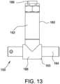
- the pivot member 150 includes a first portion 160 to adjust the roll of the screen and a second portion 163 that extends from the first portion 160 to adjust the pitch of the screen.
- the first portion 160 of the pivot member 150 is perpendicular to the second portion 163.
- the pivot member 150 includes sleeves, bearings and/or bushings to allow the screen to pivot with respect to the remainder of the apparatus.
- the first portion 160 contains a first portion sleeve 162 and a first shaft 166 that extends through the sleeve 162.
- the first portion sleeve 162 is attached to a frame 152 ( Fig. 15 ) that supports the screens to allow the frame 152 and screens to pivot about the shaft 166 to adjust the roll of the screens.
- the second portion 163 includes a second portion sleeve 168.
- the first shaft 166 is attached to the second portion sleeve 168.
- a second shaft 164 extends through the second portion sleeve 168 and is connected to the bracket 155 ( Fig. 15 ).
- the second sleeve 168 and the screens pivot about the shaft 164 to adjust the pitch of the screens.
- each of the first and second portions 160, 163 may include a bushing or bearing such as a ball bearing or roller
- the adjustment system 148 includes a first actuator 154A ( Fig. 9 ) and a second actuator 154B (shown as hydraulic cylinders) which work in cooperation with the pivot member 150 to adjust the pitch and roll of the vibratory screen 109.
- a sensor 158 ( Fig. 16 ) senses the pitch and/or roll of the screen. In other embodiments, two separate sensors detect the pitch and roll, respectively.
- the sensor 158 produces a signal that is transmitted to a controller 144.
- the controller 144 may be the same controller 44 described below for controlling the flow of liquids in the fluid storage and supply system 25 ( Fig. 1 ) or may be a separate controller 144 that includes similar components (e.g., contains processors, memory and the like as described below).
- the controller 144 controls the actuators 154A, 154B based on input from the sensor 158. Generally, the controller 144 controls the actuators 154A, 154B to eliminate roll within the screen (i.e., the screen is laterally level). The controller 144 may control the actuators 154A, 154B to achieve a target pitch of the screen 109. For example, the screen 109 may be adjusted to have a positive pitch, negative pitch or to be level. The operator may select a pitch by a user interface (not shown) that is communicatively coupled to the controller 144.
- the pivot member 150 is aligned with the outlet 71 of the airlock 55 relative to the lateral axis B ( Fig. 3A ) of the apparatus 3.
- the airlock outlet 71 has a width W and the pivot member 150 is laterally aligned with the width W of the outlet 71.
- the pivot member 150 may be located relatively near the airlock 55 relative to the longitudinal axis A ( Fig. 3A ) such that the screen upon which material is loaded from the airlock 55 pivots a relatively small amount near the airlock 55 which allows the vertical profile of the apparatus to be reduced.
- the conveyor 133 has a rear 170 toward which material is loaded onto the belt from the airlock outlet 71 and a front 172 toward which material is discharged from the screen.
- a center plane E is midway between the rear 170 and the front 172.
- the pivot member 150 is rearward to the center plane E of the screen 133 relative to the longitudinal axis A ( Fig. 3A ) (i.e., the pivot member 150 is nearer the rear 170 than the front 172 of the screen).
- the airlock 55 has a bottom 175.
- the bottom 175 of the airlock 55 and the rear 170 of the screen are separated by a distance D1 relative to the longitudinal axis A ( Fig 3A ).
- the bottom 175 of the airlock 55 and the front 172 of the screen 133 are separated by a distance D2 relative to the longitudinal axis A.
- the distance D1 between the bottom 175 of the airlock 55 and the rear 170 of the screen 133 is less than the distance D2 between the bottom 175 of the airlock 55 and the front 172 of the screen 133.
- the pivot member 150 of the illustrated embodiment allows two degrees of freedom (e.g., roll and pitch) in which to adjust the screen.
- the apparatus 3 does not include a panhard rod to eliminate a third degree of freedom (e.g., yaw).
- the hydro excavation vacuum apparatus 3 includes a fluid storage and supply system 25 ( Fig. 1 ) which supplies water for high pressure excavation and stores water recovered from the dewatering system 95.
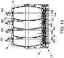
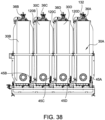
- the fluid storage and supply system 25 includes a plurality of vessels 30 for holding fluid.
- the vessels 30 are sections of a baffled tank 32 ( Fig. 18 ) with the vessels 30 being separated by baffles 35.
- the tank baffles 35 generally extend from the bottom 40 to the top 42 of each vessel 30 such that fluid does not pass over the baffles 35 into adjacent vessels.
- the vessels 30 are separate tanks.
- water is not processed when transferred between tanks (e.g., further purification such as by centrifugation in hydrocyclones or by addition of additives such as flocculants or coagulants).
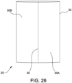
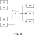
- the fluid storage and supply system 25 includes four vessels 30.
- the system 25 may include two vessels 30 ( Fig. 26 ), three vessels 30 ( Fig. 27 ) or more than four vessels 30 (e.g., five, six or more vessels).
- the fluid storage and supply system 25 carries fluid used for high pressure excavation.
- the hydro excavation vacuum apparatus 3 processes earth cuttings and reclaimed water from the excavation site with reclaimed water being stored in the fluid storage and supply system 25.
- the initial water used for excavation i.e., water not having been processed through the dewatering system 95 of the apparatus 3) may be referred herein as "maiden water.”
- Water that has been reclaimed from the excavation site and stored in the fluid storage and supply system 25 may be referred to herein as "first cycle water.”
- first cycle water may be used as the source of water for high pressure excavation.
- the reclaimed water may be referred to as "second cycle water.” Additional cycles may be performed to produce “third cycle water,” “fourth cycle water,” and so on.
- the fluid storage and supply system 25 is adapted to allow maiden water to remain separated from first cycle water without having dedicated empty tank space to reduce the volume of tanks carried on the apparatus 3.
- the fluid storage and supply system 25 includes a first vessel 30A.
- the first vessel 30A is in fluid communication with the excavation fluid pump 6 ( Fig. 3B ).
- the system 25 may include a first vessel pump 38A that may provide head pressure for the excavation fluid pump 6 or that may be used to empty out the first vessel 30A. In other embodiments, the first vessel pump 38A is eliminated.
- the fluid storage and supply system 25 also includes a second vessel 30B that is in fluid communication with the dewatering system 95 to receive first cycle water discharged from the dewatering system 95.
- a return water pump 110 ( Fig. 14 ) conveys first cycle water from the catchpan 112 of the dewatering system 95 to the second vessel 30B.
- the return water pump 110 may operate upon activation of a float or may run continually to move first cycle water to the second vessel 30B.
- a first vessel level sensor 36A measures the level of fluid in the first vessel 30A and a second vessel level sensor 36B measures the level of fluid in the second vessel 30B.
- a second vessel transfer pump 38B pumps fluid from the second vessel 30B (e.g., to the first vessel 30A as in two vessel embodiments or to a third vessel as in embodiments having three or more vessels).
- the system 25 includes a third vessel 30C or even a fourth vessel 30D.
- the third vessel 30C is in fluid communication with the second vessel 30B.
- the second vessel transfer pump 38B transfers fluid from the second vessel 30B into the third vessel 30C.
- a third vessel transfer pump 38C transfers fluid to the first vessel 30A or, in embodiments in which the system 25 includes a fourth vessel, to the fourth vessel 30D.
- a third vessel level sensor 36C senses the fluid level in the third vessel 30C.
- the fourth vessel 30D is in fluid communication with the third vessel 30C.
- a fourth vessel level sensor 36D senses the fluid level in the fourth vessel 30D.
- a fourth vessel transfer pump 38D transfers fluid from the fourth vessel 30D to the first vessel 30A.
- the level sensors 36A, 36B, 36C, 36D may be ultrasonic sensors, radar sensors, capacitance sensors, float sensors, laser sensors or the like.
- the vessels 30 of the fluid storage and supply system 25 may be separate compartments of a single tank as shown in Figures 18-27 or may be separate tanks or may be a combination of compartmentalized tanks and separate tanks.
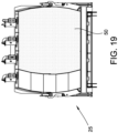
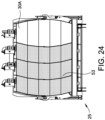
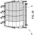
- Cycling of water within the fluid storage and supply system 25 is illustrated in Figures 19-25 . While cycling of water in the system 25 may be described and shown with reference to four vessels 30, the description is also applicable to two or three vessel systems unless stated differently.
- the first vessel 30A and, if equipped and as in the embodiment of Figure 19 , the third vessel 30C, and fourth vessel 30D, are filled with maiden water 50, indicated by stippling.
- the source of maiden water may be potable water, surface water (e.g., pond, river, ditch water) or grey water substantially fee of abrasive grit.
- the maiden water 50 in the first vessel 30A has an initial level.
- the hydro vacuum excavating apparatus 3 is then transported from the site at which the vessels are filed with maiden water to a second site at which a high-pressure water excavation is performed.
- the excavation fluid pump 6 Fig.
- the vacuum system 7 ( Fig. 1 ) causes spoil material to become entrained in an airstream and pass through the boom 9 and other conduits and into the separation vessel 21. Spoil material is separated from the airstream by the separation vessel 21 and cyclones 11.
- the spoil material is introduced into the dewatering system 95 through airlock 55 and/or pumped from the cyclone discharge pump 20.
- the first cycle water is separated from spoil material in the dewatering system 95.
- the separated first cycle water is directed to the second vessel 30B. Solids discharged from the dewatering system 95 falls into a hopper 125 ( Fig. 1 ) and are conveyed from the hopper 125 by a conveyor assembly 127 to form a stack of solids.
- maiden water 50 is drawn from the first vessel 30A causing the level of fluid in the first vessel 30A to be reduced below the initial level ( Fig. 20 ).
- the first vessel level sensor 36A senses the reduction in the fluid level in the first vessel 30A. Once the level of maiden water in the first vessel 30A is reduced to below the initial level or is even reduced further (e.g., reduced to a level of about 99% of the initial level or less, about 95% or less, about 90% or less, about 50% or less, about 25% or less, about 10% less or when the first vessel 30A is emptied of maiden water 50), additional maiden water 50 is transferred to the first vessel 30A.
- maiden water may be pumped from the fourth vessel 30D into the first vessel 30A to maintain a level of fluid in the first vessel 30A for excavation.
- maiden water may be pumped from the third vessel 30C into the first vessel 30A.
- additional maiden water may be directed toward the excavation site after the volume of the maiden water used for excavation is at least the volume of the first vessel 30A (i.e., additional excavation may be performed after the volume of maiden water in the first vessel 30A is consumed). Water may be transferred within the system 25 as excavation is being performed and the dewatering system 95 operates.
- the level of fluid in the fourth vessel 30D is reduced.
- the level of fluid in the fourth vessel 30D is reduced to below the initial level or less (e.g., to a level of about 99% of the initial level or less, or about 95% or less, about 90% or less, about 50% or less, about 25% or less, about 10% less or when the fourth vessel is emptied of maiden water)
- maiden water from the third vessel 30C is transferred to the fourth vessel 30D ( Fig. 21 ).
- first cycle water 53 is transferred from the second vessel 30B into the third vessel 30C ( Fig. 23 ).
- first cycle water 53 from the third vessel 30C may be pumped to the fourth vessel 30D ( Fig. 24 ).
- first cycle water may be used for excavation.
- the first cycle water 53 may be transferred into the first vessel 30A ( Fig. 25 ).
- the excavation fluid pump 5 ( Fig. 3B ) directs pressurized first cycle water 53 from the first vessel 30A toward an excavation site to cut earthen material.
- the cut earth and first cycle water (now second cycle water) are removed from the excavation site.
- the second cycle water is separated from the cut earthen material in the dewatering system 95 ( Fig. 1 ) with the second cycle water being introduced into the second vessel 30B.
- the second cycle water is subsequently introduced into the third vessel 30C, fourth vessel 30D, and/or first vessel 30A.
- the second cycle water may be used for excavation by transferring second cycle water into the first vessel 30A.
- the excavation fluid pump 6 directs pressurized second cycle water from the first vessel 30A toward an excavation site. Additional cycles may be performed to reuse reclaimed water and reduce the frequency at which maiden water is loaded onto the apparatus.
- the fluid processed through the dewatering system 95 e.g., first cycle water, second cycle water, etc.
- the fluid storage and supply system 25 is monitored to determine if the fluid is suitable for use for excavation.
- the fluid may be monitored manually or automatically.
- the fluid may be monitored by measuring clarity, translucence, conductivity, viscosity, specific gravity, or the like.
- Fluid that is unsuitable for excavation may be disposed (e.g., municipal water treatment) or may be treated in a separate reclamation system (e.g., with coagulant or flocculant treatment).
- An example reclamation system is disclosed in U.S. Provisional Patent Application No. 62/444,567, filed January 10, 2017 , entitled “Systems and Methods for Dosing Slurries to Remove Suspended Solids," which is incorporated herein by reference for all relevant and consistent purposes.
- FIG. 38 Another embodiment of the fluid storage and supply system 25 is shown in Figures 38 and 39 .
- the system 25 generally includes the components of the system described above with several differences being described below.
- the drive motor 34 of each pump 38 (first motor 34A and first vessel pump 38A being shown in Figure 39 ) is disposed above the vessel 30A.
- the bottom 40 of each vessel 30 angles downward toward the pump 38 to allow the vessels to be more fully emptied.
- At least one of the vessels 30 such as the first vessel 30A ( Fig. 39 ) includes an airgap device 132 as shown in Figure 40 to prevent siphoning and cross-contamination through the transfer pipes 120.
- the system 25 includes a discharge manifold 107 for offloading water from the system 25 (e.g., recycled water such as first cycle water, second cycle water or the like).
- the system 25 includes valves 45A, 45B, 45C, 45D that are actuated to selectively move water within the system.
- the first valve 45A is positioned to direct maiden water discharged from the first vessel pump 38A to the excavation pump 6 ( Fig. 3B ).
- the second, third, and fourth valves 45B, 45C, 45D are positioned to direct water (e.g., maiden water or recycled water depending on how much maiden water and recycled water is in the system) to the next vessel in the system 25.
- valve 45A, 45B, 45C, 45D may be positioned such that water drains into the discharge manifold 107.
- the discharge manifold 107 includes an outlet through which water may exit the system 25.
- the discharge manifold 107 may be used while filling the system 25 with maiden water.
- maiden water is directed into the first vessel 30A ( Fig. 38 ) through airgap device 132.
- the first pump 38A is operated and the valve 45A is positioned to direct maiden water from the first vessel 30A to the discharge manifold 107 ( Fig. 41 ).
- the outlet of the discharge manifold is closed such that the manifold 107 fills with water.
- the third and fourth vales 45C, 45D are positioned to allow maiden water to flow from the manifold 107, through pumps 38C, 38D (i.e., pumps 38C, 38C are off and water is caused to back-flow through pumps 38C, 38D).
- first, third and fourth vessels 30A, 30C, 30D can be filled with maiden water.
- the second valve 45B is positioned such that the second tank 30B is not in fluid communication with the manifold 107 to allow the second tank 30B to remain empty to receive first cycle water.
- the system 25 may be automated by controlling the first pump 38A to cause the first, third and fourth vessels 30A, 30C, 30D to be at or near the same level during filling (e.g., by use of level sensors 36A, 36C, 36D).
- each valve 45 includes a plunger 111.
- the plunger 111 directs fluid that is received from the transfer pump in transfer pump conduit 115 to the transfer pipe 120 that is in fluid communication with the next vessel in the system 25 or with the excavation pump 6 ( Fig. 3B ).
- fluid is directed from the transfer pump conduit 115 to the discharge conduit 124 which is connected to the discharge manifold 107 ( Fig. 40 ) (or flows in the reverse direction such that maiden water flows from the manifold 107 to the tanks 30C, 30D such as when filling the system 24 with maiden water).
- the valve 45 is actuated by hand by lever 130. In other embodiments, actuation of each valve 45 is automated.
- the fluid storage and supply system 25 includes a controller 44 ( Fig. 28 ) that enables the second vessel transfer pump 38B, third vessel transfer pump 38C, and/or the fourth vessel transfer pump 38D to operate based at least in part on an output signal from the first vessel level sensor 36A, second vessel level sensor 36B, third vessel level sensor 36C, and/or fourth vessel level sensor 36D.
- the controller 44 is communicatively coupled to the second vessel transfer pump 38B, third vessel transfer pump 38C, and the fourth vessel transfer pump 38D.
- the controller 44 selectively powers the pumps 38B, 38C, 38D to move maiden water and first cycle water within the vessels 30A, 30B, 30C, 30D as discussed further herein.
- the controller 44 may also be communicatively or operatively coupled to the first vessel pump 38A (e.g., to operate the pump 38A when the excavation pump 6 is operating or to unload all fluid from the first vessel 30A).
- the controller 44 may control the pumps 38B, 38C, 38D based on instructions stored in a memory device (not shown), input received from sensors 36A, 36B, 36C, 36D, input from a user via a user interface, and/or input received from any other suitable data source.
- Controller 44 the various logical blocks, modules, and circuits described herein may be implemented or performed with a general purpose computer, a digital signal processor (DSP), an application specific integrated circuit (ASIC), a field programmable gate array (FPGA), or other programmable logic device, discrete gate or transistor logic, discrete hardware components, or any combination thereof designed to perform the functions described herein.
- Example general purpose processors include, but are not limited to only including, microprocessors, conventional processors, controllers, microcontrollers, state machines, or a combination of computing devices.
- Controller 44 includes a processor, e.g., a central processing unit (CPU) of a computer for executing instructions. Instructions may be stored in a memory area, for example. Processor may include one or more processing units, e.g., in a multi-core configuration, for executing instructions. The instructions may be executed within a variety of different operating systems on the controller, such as UNIX, LINUX, Microsoft Windows ® , etc. It should also be appreciated that upon initiation of a computer-based method, various instructions may be executed during initialization. Some operations may be required in order to perform one or more processes described herein, while other operations may be more general and/or specific to a particular programming language e.g., and without limitation, C, C#, C++, Java, or other suitable programming languages, etc.
- a processor e.g., a central processing unit (CPU) of a computer for executing instructions. Instructions may be stored in a memory area, for example. Processor may include one or more processing units, e.g
- Storage device is any computer-operated hardware suitable for storing and/or retrieving data.
- storage device is integrated in controller.
- storage device is external to controller and is similar to database.
- controller may include one or more hard disk drives as storage device.
- storage device is external to controller.
- storage device may include multiple storage units such as hard disks or solid state disks in a redundant array of inexpensive disks (RAID) configuration.
- Storage device may include a storage area network (SAN) and/or a network attached storage (NAS) system.
- SAN storage area network
- NAS network attached storage
- processor is operatively coupled to storage device via a storage interface.
- Storage interface is any component capable of providing processor with access to storage device.
- Storage interface may include, for example, an Advanced Technology Attachment (ATA) adapter, a Serial ATA (SATA) adapter, a Small Computer System Interface (SCSI) adapter, a RAID controller, a SAN adapter, a network adapter, and/or any component providing processor with access to storage device.
- ATA Advanced Technology Attachment
- SATA Serial ATA
- SCSI Small Computer System Interface
- RAID controller a SAN adapter
- network adapter operatively coupled to storage device via a storage interface.
- Memory area may include, but are not limited to, random access memory (RAM) such as dynamic RAM (DRAM) or static RAM (SRAM), read-only memory (ROM), erasable programmable read-only memory (EPROM), electrically erasable programmable read-only memory (EEPROM), and non-volatile RAM (NVRAM).
- RAM random access memory
- DRAM dynamic RAM
- SRAM static RAM
- ROM read-only memory
- EPROM erasable programmable read-only memory
- EEPROM electrically erasable programmable read-only memory
- NVRAM non-volatile RAM
- the fluid storage and supply system 25 includes a valving system 48 ( Fig. 29 ) for switching the source of water used for high pressure excavation from vessel to vessel.
- the valving system 48 allows one of the first vessel 30A, 30B, 30C, 30D to be in fluid communication with the fluid excavation pump 6 and wand 4. In this manner, additional maiden pressurized water may be directed toward the excavation site after the volume of the maiden pressurized water used for excavation is at least the volume of the first vessel 30A (i.e., additional excavation may be performed after the volume of maiden water in the first vessel 30A is consumed).
- the valving system 48 may include hand-operated valves for switching the source of water used for excavation or the system 48 may include a controller (not shown) which controls the valving system 48 based on, at least in part, a signal from at least one of the first vessel level sensor 36A, the second vessel level sensor 36B, the third vessel level sensor 36C, and the fourth vessel level sensor 36D.
- a valving system (not shown) may be used to select which vessel 30A, 30B, 30C, 30D is filled with first cycle water (i.e., a valving system disposed between the dewatering system 95 and the fluid storage and supply system 25).
- a valving system (not shown) may be used to transfer fluid between vessels 30A, 30B, 30C, 30D.
- the hydro excavation vacuum apparatus is a mobile apparatus capable of recycling the water used for excavation such that the apparatus may be used to excavate one or more sites during daily use (e.g., for 8, 10 or 12 or more hours) without re-filling with maiden water and/or disposing of reclaimed water.
- the apparatus 3 may include vessels that are filled with maiden water before excavation begins with relatively little empty tank space (e.g., with 1250 gallon, 1500 gallon, 1750 gallon or more maiden water carrying capacity).
- the system may generate a vacuum of at least 18" Hg at 3000 standard cubic feet per minute.
- the dwell time of air passing through the separation vessel 21 may be less than about 5 seconds.
- a vibratory screen used to separate solids may have openings of 250 microns or less.
- the system may be adapted to process larger solids such as solids generated when a rotary wand is used to excavate a site (e.g., solids with a nominal diameter up to the size of the vacuum system conduits such as up to 6").
- the system may include a deceleration system having a deceleration vessel and deflection plate which allows solids to be quickly directed toward the airlock.
- the deceleration vessel allows a large volume of air and cut earth and water to be processed in a relatively compact vessel which reduces the footprint of the separation vessels to be reduced.
- the deceleration vessel may be more compact than a cyclone in which materials are vortexed as the cyclone should have a sufficiently large spoil material outlet to let larger solids to pass but typically only operate efficiently within a small range of length to diameter ratios.
- a single deceleration vessel may be used which further reduces cost and the footprint of the dewatering system.
- the solid material contacts liquid for a relatively small amount of time which reduces absorption of liquid by the solid particles which allows the particles to more easily travel over screens in downstream screening operations and allows at least some material to be processed before becoming a slurry which reduces water usage. Reducing dwell time also allows the size of the separation vessel to be reduced which reduces size and weight of the apparatus.
- the airlock discharges directly to the dewatering screens of the dewatering system without intermediate processing (e.g., without centrifugation)
- the amount of time the solid earthen material contacts liquid may be further reduced which improves separation of solids from the liquid.
- air may be pulled into the airlock near the vertex at a relatively high velocity, which causes the cut earthen material and water resting on the vane rotating into the opening to be agitated which promotes material to fall from the vane.
- the airlock includes a relatively small number of vanes (e.g., less than 15 or less than 10) and corresponding pockets
- relatively large solids may be processed through the airlock.
- the number of vanes and the vane length may be selected to allow the pockets to accommodate the largest size of cut earthen material that may fit through the vacuum conduit.
- the airlock rotates relatively slowly (e.g., less than 10 RPM)
- the amount of air that passes into the airlock into the vacuum system may be reduced.
- the vacuum system includes a positive displacement vacuum pump to increase the capacity and the vacuum generated by the system to allow larger solids to be processed (e.g., generating a vacuum of at least 18" Hg at 3000 cubic feet per minute).
- maiden water may remain separated from first cycle water with a reduced amount of tank space on the apparatus (e.g., a reduced amount of empty tank space after filling with maiden water before excavation has begun).
- the dewatering system includes a pre-screen that separates larger solids before the spoil material contacts a downstream vibratory screen (e.g., a pre-screen with large openings such the ratio of the size of the pre-screen openings to the size of the openings of the vibratory screen is at least about 100:1)
- a downstream vibratory screen e.g., a pre-screen with large openings such the ratio of the size of the pre-screen openings to the size of the openings of the vibratory screen is at least about 100:1
- the downstream vibratory screen may be protected from impact with the large solids which reduces damage and fouling of the vibratory screen.
- the system includes a pitch and roll adjustment system with a pivot member that is laterally aligned with the outlet of the airlock
- rolling of the screen e.g., pre-screen, vibratory screen, or flat wire belt conveyor
- the pivot member is positioned rearward to a center plane of the screen (i.e., closer to the rear of the screen)
- the screen moves less near the airlock when the pitch of the screen is adjusted. This allows for less clearance between the screen and airlock and the vertical profile of the apparatus may be reduced. This also allows the spoil material to travel along a longer length of the screen which promotes separation of water from the spoil material.
- solid materials By processing spoil material onboard the apparatus, solid materials may be separated to allow the spoil material (e.g., first pass water) to be more efficiently stored on the apparatus due to the smaller volume of the material. Separating solids allows the recovered water to be used for excavation in one or more cycles. Separated solids may be used for backfilling the excavation site which reduces the cost of the excavation operation and allows for efficient use of solids.
- the spoil material e.g., first pass water
- the conveyors can remove material from the solids outlet of the cyclones which reduces or prevents pluggage of the cyclone outlets.
- Use of sealed conveyors and peristaltic pumps prevents air from entering the system from the ambient atmosphere.
- the fluid storage and supply system includes a manifold connected to the vessels of the system and valves that may be actuated to allow the vessels to be filled from the manifold
- the first vessel pump may be operated to quickly fill additional tanks with maiden water through the manifold.
- Use of an airgap device prevents contamination of maiden water through backflow.
- the terms “about,” “substantially,” “essentially” and “approximately” when used in conjunction with ranges of dimensions, concentrations, temperatures or other physical or chemical properties or characteristics is meant to cover variations that may exist in the upper and/or lower limits of the ranges of the properties or characteristics, including, for example, variations resulting from rounding, measurement methodology or other statistical variation.
- a hydro excavation vacuum apparatus for excavating earthen material comprising:
- Clause 3 The hydro excavation vacuum apparatus as set forth in clause 1 wherein a ratio of the size of the openings of the pre-screen to the size of the openings of the vibratory screen is at least about 100:1.
- the hydro excavation vacuum apparatus as set forth in clause 1 further comprising a shaker assembly comprising the vibratory screen, the shaker assembly adapted to move the vibratory screen linearly or in an elliptical path.
- Clause 8 The hydro excavation vacuum apparatus as set forth in clause 1 wherein the vacuum system comprises a vacuum pump, the vacuum pump being capable of generating a vacuum of at least 18" Hg at 3000 cubic feet per minute.
- Clause 10 The hydro excavation vacuum apparatus as set forth in clause 1 wherein the apparatus does not include hydrocyclones for separating water from earthen material.
- a hydro excavation vacuum apparatus for excavating earthen material comprising:
- Clause 12 The hydro excavation vacuum apparatus as set forth in clause 11 wherein the wand comprises a rotary nozzle for directing water in a rotating, circular path toward the earthen material at the excavation site.
- Clause 14 The hydro excavation vacuum apparatus as set forth in clause 11 wherein a ratio of the size of the openings of the pre-screen to the size of the openings of the vibratory screen is at least about 250:1.
- Clause 17 The hydro excavation vacuum apparatus as set forth in clause 11 wherein the apparatus does not include hydrocyclones for separating water from earthen material.
- a hydro excavation vacuum apparatus for excavating earthen material comprising:
- Clause 19 The hydro excavation vacuum apparatus as set forth in clause 18 wherein the deflection plate comprises a wear plate connected to a support.
- Clause 20 The hydro excavation vacuum apparatus as set forth in clause 18 further comprising an inlet conduit connected to the deceleration vessel inlet, the inlet conduit having a longitudinal axis, the longitudinal axis of the conduit passing through a central vertical axis of the deceleration vessel.
- Clause 21 The hydro excavation vacuum apparatus as set forth in clause 18 wherein the deflection plate includes a material-engaging face having a longitudinal plane, the longitudinal plane of the material-engaging face forming an angle with a vertical axis of the deceleration vessel.
- Clause 23 The hydro excavation vacuum apparatus as set forth in clause 18 further comprising a wand for directing pressurized water toward earthen material to cut the earthen material, the wand comprising a rotary nozzle for directing water in a rotating, circular path toward the earthen material at an excavation site.
- Clause 24 The hydro excavation vacuum apparatus as set forth in clause 18 wherein the deceleration vessel comprises a lower portion that tapers inward toward the spoil material outlet.
- Clause 25 The hydro excavation vacuum apparatus as set forth in clause 18 wherein the deceleration vessel comprises an air outlet disposed above the inlet.
- Clause 26 The hydro excavation vacuum apparatus as set forth in clause 25 wherein the deceleration vessel comprises a plurality of air outlets, each outlet being fluidly connected to a cyclone to separate material entrained in an airstream withdrawn from the outlets.
- Clause 27 The hydro excavation vacuum apparatus as set forth in clause 18 wherein the deceleration vessel is adapted such that the airstream is not circulated within the deceleration vessel.
- Clause 28 The hydro excavation vacuum apparatus as set forth in clause 18 wherein the deceleration vessel has an effective cross-sectional area, the hydro excavation vacuum apparatus comprising a deceleration vessel inlet conduit having an effective cross-sectional area, a ratio of the effective cross-sectional area of the deceleration vessel to the effective cross-sectional area of the inlet conduit being at least about 7.5:1 to reduce the velocity of the airstream to allow material to fall from the airstream.
- a vacuum excavation apparatus for excavating earthen material comprising:
- the vacuum excavation apparatus as set forth in clause 29 further comprising a wand for directing pressurized water toward earthen material to cut the earthen material, the wand comprising a rotary nozzle for directing water in a rotating, circular path toward the earthen material at an excavation site.
- Clause 36 The vacuum excavation apparatus as set forth in clause 29 wherein the deceleration vessel has an effective cross-sectional area, the hydro excavation vacuum apparatus comprising a deceleration vessel inlet conduit having an effective cross-sectional area, a ratio of the effective cross-sectional area of the deceleration vessel to the effective cross-sectional area of the inlet conduit being at least about 7.5:1 to reduce the velocity of the airstream to allow material to fall from the airstream.
- a method for hydro excavating a site with an excavation apparatus comprising:
- Clause 38 The method as set forth in clause 37 wherein the airstream has a dwell time of less than about 3 seconds in the separation vessel or less than about 1 second.
- Clause 39 The method as set forth in clause 37 wherein the separation vessel is a deceleration vessel adapted such that the airstream is not circulated within the deceleration vessel.
- Clause 40 The method as set forth in clause 39 wherein the apparatus comprises an inlet conduit connected to a deceleration vessel inlet, the inlet conduit having a longitudinal axis, the longitudinal axis of the conduit passing through a central vertical axis of the deceleration vessel.
- Clause 41 The method as set forth in clause 37 further comprising a vacuum system for removing cut earthen material and water from the excavation site, the vacuum system being capable of generating a vacuum of at least 18" Hg at 3000 cubic feet per minute.
- a hydro excavation vacuum apparatus for excavating earthen material comprising:
- Clause 43 The hydro excavation vacuum apparatus as set forth in clause 42 wherein the fluid storage and supply system comprises a third vessel in fluid communication with the second vessel, the second vessel transfer pump transferring fluid from the second vessel into the third vessel.
- Clause 45 The hydro excavation vacuum apparatus as set forth in clause 44 wherein the fluid storage and supply system comprises a fourth vessel in fluid communication with the third vessel, the third vessel transfer pump transferring fluid from the third vessel into the fourth vessel.
- Clause 47 The hydro excavation vacuum apparatus as set forth in clause 46 wherein the fluid storage and supply system further comprises a controller that enables the second vessel transfer pump, third vessel transfer pump, and/or the fourth vessel transfer pump to operate based at least in part on an output signal from the first vessel level sensor, second vessel level sensor, third vessel level sensor, and/or fourth vessel level sensor.
- Clause 48 The hydro excavation vacuum apparatus as set forth in clause 42 wherein the first vessel and the second vessel are separate tanks.
- Clause 50 The hydro excavation vacuum apparatus as set forth in clause 42 wherein the first vessel level sensor and the second vessel level sensor are selected from ultrasonic sensors, radar sensors, capacitance sensors, float sensors and laser sensor.
- a hydro excavation vacuum apparatus for excavating earthen material comprising:
- Clause 52 The hydro excavation vacuum apparatus as set forth in clause 51 comprising a fourth vessel for receiving fluid from the third vessel.
- Clause 53 The hydro excavation vacuum apparatus as set forth in clause 52 wherein the first vessel, second vessel, third vessel, and fourth vessel are separate tanks.
- Clause 54 The hydro excavation vacuum apparatus as set forth in clause 52 wherein the first vessel, second vessel, third vessel, and fourth vessel are separate compartments of a single tank.
- Clause 55 The hydro excavation vacuum apparatus as set forth in clause 51 wherein the fluid storage and supply system comprises a second vessel transfer pump for transferring fluid from the second vessel to the third vessel.
- Clause 56 The hydro excavation vacuum apparatus as set forth in clause 51 wherein the fluid storage and supply system comprises a third vessel transfer pump for transferring fluid from the third vessel to the first vessel.
- Clause 58 The hydro excavation vacuum apparatus as set forth in clause 51 wherein the first vessel, second vessel, and third vessel are separate compartments of a single tank.
- a method for hydro excavating a site with an excavation apparatus having at least two vessels for supplying and storing excavation fluid comprising:
- Clause 60 The method as set forth in clause 59 wherein additional maiden water is introduced into the first vessel upon the level of maiden water in the first vessel being reduced to a level of about 99% or less.
- Clause 62 The method as set forth in clause 61 further comprising transferring the first cycle water from the second vessel into the third vessel after the third vessel is emptied of maiden water.
- Clause 63 The method as set forth in clause 59 further comprising:
- Clause 64 The method as set forth in clause 63 wherein additional maiden water is introduced into the fourth vessel upon the level of maiden water in the fourth vessel being reduced to a level of about 99% or less.
- Clause 65 The method as set forth in clause 63 further comprising:
- Clause 68 The method as set forth in clause 59 wherein providing maiden water in a first vessel of the apparatus includes filling the first vessel with maiden water at a first site, the method further comprising transporting the apparatus to a second site and performing an excavation at the second site.
- a hydro excavation vacuum apparatus for excavating earthen material comprising:
- Clause 71 The hydro excavation vacuum apparatus as set forth in clause 70 wherein the valving system comprises hand-operated valves for switching the source of water directed through the wand from the first vessel to the second vessel.
- Clause 72 The hydro excavation vacuum apparatus as set forth in clause 70 wherein the fluid storage and supply system comprises a controller for switching the source of water directed through the wand from the first vessel to the second vessel.
- Clause 74 The hydro excavation vacuum apparatus as set forth in clause 70 wherein the fluid storage and supply system further comprises a fourth vessel.
- Clause 75 The hydro excavation vacuum apparatus as set forth in clause 70 wherein the first vessel, second vessel, and third vessel are separate tanks.
- Clause 76 The hydro excavation vacuum apparatus as set forth in clause 70 wherein the first vessel, second vessel, and third vessel are separate compartments of a single tank.
- a method for hydro excavating a site with an excavation apparatus having at least two vessels for supplying and storing excavation fluid comprising:
- Clause 78 The method as set forth in clause 77 wherein the source of additional maiden water is maiden water in a third vessel.
- Clause 79 The method as set forth in clause 78 wherein a wand directs pressurized water toward earthen material to cut the earthen material and a valving system switches the source of maiden water from the first vessel to the third vessel.
- Clause 80 The method as set forth in clause 77 wherein the source of additional maiden water is maiden water transferred into the first vessel from a third vessel.
- An airlock for conveying material comprising:
- Clause 84 The airlock as set forth in clause 82 wherein the outlet tapers from the vertex toward the first sidewall along a curved path and tapers from the vertex toward the second sidewall along a curved path.
- Clause 85 The airlock as set forth in clause 81 wherein the outer annular wall has a center midway between the first and second sidewalls, the vertex being at the center of the outer annular wall.
- a hydro excavation vacuum apparatus for excavating earthen material comprising:
- a method for hydro excavating a site with an excavation apparatus comprising:
- Clause 91 The method as set forth in clause 90 wherein the vanes of the airlock rotate at a speed of less than 5 RPM to move cut earthen material and water from the airlock inlet toward the airlock outlet.
- Clause 92 The method as set forth in clause 90 wherein pressurized water is directed toward an excavation site through a wand, the wand comprising a rotary nozzle that rotates a jet of water to cut earthen material at the excavation site.
- a hydro excavation vacuum apparatus for excavating earthen material comprising:
- each pocket has a bottom, top and a mid-point midway between the top and the bottom, the pocket having a width at the mid-point, the width being at least D 1 .
- Clause 96 The hydro excavation vacuum apparatus as set forth in clause 93 further comprising a dewatering system having one or more vibratory screens, the airlock discharging into the dewatering system.
- a hydro excavation vacuum apparatus for excavating earthen material at an excavation site having a lateral axis and comprising:
- a hydro excavation vacuum apparatus for excavating earthen material at an excavation site having a longitudinal axis and comprising:
- a hydro excavation vacuum apparatus for excavating earthen material having a longitudinal axis and comprising:
- Clause 116 The hydro excavation vacuum apparatus as set forth in clause 114 wherein the second portion extends from the first portion.
- Clause 118 The hydro excavation vacuum apparatus as set forth in clause 114 wherein the first portion comprises a first portion bushing that pivots about a first shaft.
- Clause 119 The hydro excavation vacuum apparatus as set forth in clause 114 wherein the second portion comprises a second portion bushing that pivots about a second shaft.
- a cyclonic separation system for separating material entrained in an airstream comprising:
- Clause 122 The cyclonic separation system as set forth in clause 121 wherein the discharge pump is a peristaltic pump.
- Clause 127 The cyclonic separation system as set forth in clause 121 comprising two or more cyclones, wherein at least two cyclones discharge into the sealed conveyor.
- Clause 129 The cyclonic separation system as set forth in clause 121 wherein the one or more cyclones having a longitudinal axis, the longitudinal axis of the cyclones being orthogonal of a longitudinal axis of the conveyor.
- Clause 132 The cyclonic separation system as set forth in clause 130 wherein the sealed conveyor comprises one or more gaskets for sealing the conveyor.
- a hydro excavation apparatus comprising:
- Clause 134 The hydro vacuum excavation apparatus as set forth in clause 133 further comprising a separation vessel for removing cut earthen material and water from the airstream, the separation vessel being in fluid communication with the cyclones such that the airstream discharged from the separation vessel is introduced into the cyclones.
- a hydro excavation vacuum apparatus for excavating earthen material comprising:
- Clause 139 The hydro excavation vacuum apparatus as set forth in clause 135 wherein the fluid storage and supply system further comprises an airgap device connected to one of the vessels to prevent backflow of maiden water.
- Clause 140 The hydro excavation vacuum apparatus as set forth in clause 139 wherein the fluid storage and supply system comprises a single airgap device.
- a method for filling a fluid storage and supply system of a hydro vacuum excavation apparatus comprising a first vessel, a second vessel for receiving water from a dewatering system, a third vessel, and a manifold connected to the first, second and third vessels, the method comprising:
- Clause 142 The method as set forth in clause 141 wherein the fluid storage and supply system further comprises a transfer conduit for transferring fluid from the first vessel to an excavation fluid pump, wherein actuation of the valve causes the first vessel to not be in fluid communication with excavation fluid pump.
- Clause 143 The method as set forth in clause 141 wherein the fluid storage and supply system further comprises a first vessel level sensor, a second vessel level sensor, a third vessel level sensor, and a controller, the controller being configured to control the first vessel transfer pump such that the water level in the first and third vessels is substantially the same while adding water to the first vessel.
- Clause 145 The method as set forth in clause 144 wherein the fluid storage and supply system further comprises a fourth vessel and a fourth valve, the method comprising actuating the fourth valve to cause the fourth vessel to be in fluid communication with the manifold to allow the fourth vessel to be filled with water.
- Clause 146 The method as set forth in clause 145 wherein the fluid storage and supply system comprises a first vessel level sensor, a second vessel level sensor, a third vessel level sensor, and a controller, the controller being configured to control the first vessel transfer pump such that the water level in the first, third and fourth vessels is substantially the same while adding water to the first vessel.
Landscapes
- Engineering & Computer Science (AREA)
- Mechanical Engineering (AREA)
- General Engineering & Computer Science (AREA)
- Mining & Mineral Resources (AREA)
- Civil Engineering (AREA)
- Structural Engineering (AREA)
- Chemical & Material Sciences (AREA)
- Chemical Kinetics & Catalysis (AREA)
- Cyclones (AREA)
- Separation Of Solids By Using Liquids Or Pneumatic Power (AREA)
- Processing Of Solid Wastes (AREA)
- Treatment Of Sludge (AREA)
- Vaporization, Distillation, Condensation, Sublimation, And Cold Traps (AREA)
- Excavating Of Shafts Or Tunnels (AREA)
- Drying Of Solid Materials (AREA)
Applications Claiming Priority (3)
| Application Number | Priority Date | Filing Date | Title |
|---|---|---|---|
| US201762532853P | 2017-07-14 | 2017-07-14 | |
| EP18831498.3A EP3652404B1 (de) | 2017-07-14 | 2018-07-13 | Vakuumvorrichtung für hydraulischen aushub |
| PCT/US2018/041934 WO2019014515A1 (en) | 2017-07-14 | 2018-07-13 | VACUUM APPARATUS FOR HYDRAULIC EXCAVATION |
Related Parent Applications (2)
| Application Number | Title | Priority Date | Filing Date |
|---|---|---|---|
| EP18831498.3A Division-Into EP3652404B1 (de) | 2017-07-14 | 2018-07-13 | Vakuumvorrichtung für hydraulischen aushub |
| EP18831498.3A Division EP3652404B1 (de) | 2017-07-14 | 2018-07-13 | Vakuumvorrichtung für hydraulischen aushub |
Publications (2)
| Publication Number | Publication Date |
|---|---|
| EP4461881A2 true EP4461881A2 (de) | 2024-11-13 |
| EP4461881A3 EP4461881A3 (de) | 2025-01-22 |
Family
ID=63142329
Family Applications (2)
| Application Number | Title | Priority Date | Filing Date |
|---|---|---|---|
| EP18831498.3A Active EP3652404B1 (de) | 2017-07-14 | 2018-07-13 | Vakuumvorrichtung für hydraulischen aushub |
| EP24202043.6A Pending EP4461881A3 (de) | 2017-07-14 | 2018-07-13 | Vakuumvorrichtung für hydroaushub |
Family Applications Before (1)
| Application Number | Title | Priority Date | Filing Date |
|---|---|---|---|
| EP18831498.3A Active EP3652404B1 (de) | 2017-07-14 | 2018-07-13 | Vakuumvorrichtung für hydraulischen aushub |
Country Status (5)
| Country | Link |
|---|---|
| US (8) | US11499290B2 (de) |
| EP (2) | EP3652404B1 (de) |
| AU (6) | AU2018301839B2 (de) |
| CA (5) | CA3071899C (de) |
| WO (1) | WO2019014515A1 (de) |
Families Citing this family (44)
| Publication number | Priority date | Publication date | Assignee | Title |
|---|---|---|---|---|
| WO2017015631A1 (en) * | 2015-07-22 | 2017-01-26 | Halliburton Energy Services, Inc. | Multiple platform solids transferring aggregate |
| US11111743B2 (en) * | 2016-03-03 | 2021-09-07 | Recover Energy Services Inc. | Gas tight shale shaker for enhanced drilling fluid recovery and drilled solids washing |
| DE102017108731B4 (de) * | 2017-04-24 | 2021-06-24 | Reschwitzer Saugbagger Produktions Gmbh | Saugbagger mit schwenkbarer Filtereinheit |
| CA3071899C (en) * | 2017-07-14 | 2022-02-22 | Vermeer Manufacturing Company | Hydro excavation vacuum apparatus |
| US10967300B2 (en) * | 2017-08-29 | 2021-04-06 | Green Flow Industries, LLC | Transportable separation and monitoring apparatus with auger |
| EP3543408B1 (de) * | 2018-03-21 | 2020-10-21 | BAUER Spezialtiefbau GmbH | Schlitzwandfräse und verfahren zum erstellen eines frässchlitzes im boden |
| US11525239B2 (en) | 2018-04-30 | 2022-12-13 | Vermeer Manufacturing Company | Shaker assemblies having positioning devices |
| US10946415B2 (en) | 2018-04-30 | 2021-03-16 | Vermeer Manufacturing Company | Shaker assemblies having a vibratory screen clamping system |
| CN109811816A (zh) * | 2018-12-27 | 2019-05-28 | 枞阳县中邦科技信息咨询有限公司 | 一种用于河道清理的淤泥泵 |
| CN112473252A (zh) * | 2019-09-11 | 2021-03-12 | 谭伟 | 一种多级超重力除尘器 |
| AU2020239729B9 (en) * | 2019-09-24 | 2022-01-13 | Vermeer Manufacturing Company | Systems and methods for reducing or preventing pluggage in an excavation vacuum apparatus |
| CN110617019B (zh) * | 2019-10-22 | 2023-07-21 | 贵州盘江精煤股份有限公司 | 一种用于打钻防喷的降尘装置 |
| CN111561002B (zh) * | 2020-04-09 | 2022-09-16 | 朱伟燕 | 一种水利施工用排淤装置 |
| CN111561003A (zh) * | 2020-05-12 | 2020-08-21 | 克拉玛依正义达石油科技有限责任公司 | 一种钻井废弃泥浆取出装置及其使用方法 |
| US11890782B2 (en) | 2020-06-05 | 2024-02-06 | Vermeer Manufacturing Company | Mixing systems having disk assemblies |
| US11801785B2 (en) | 2020-06-17 | 2023-10-31 | Vermeer Manufacturing Company | Vacuum excavator tank and door system |
| CN111894068A (zh) * | 2020-07-03 | 2020-11-06 | 中建新疆建工集团第五建筑工程有限公司 | 一种绞吸船用新型输泥管道及其施工方法 |
| CN112112203B (zh) * | 2020-08-18 | 2022-11-15 | 太原重工股份有限公司 | 电机直驱的挖掘机推压机构 |
| CA3092707C (en) | 2020-08-24 | 2023-01-24 | Federal Signal Corporation | Boom turret for an excavation vehicle and method thereof |
| CN111790600B (zh) * | 2020-08-25 | 2022-05-24 | 河源市金杰环保建材有限公司 | 一种水泥生产用筛分装置 |
| TW202211972A (zh) * | 2020-09-18 | 2022-04-01 | 日揚科技股份有限公司 | 氣固分離系統 |
| CN112554821B (zh) * | 2020-12-25 | 2024-07-23 | 无锡市贝安特工程机械制造有限公司 | 一种旋喷机散热装置 |
| CN112855020A (zh) * | 2021-01-18 | 2021-05-28 | 中煤科工集团重庆研究院有限公司 | 一种煤矿定向钻孔施工方法及钻具组合 |
| CN112958434A (zh) * | 2021-02-03 | 2021-06-15 | 欧佳林 | 一种纤维生产用快速除杂分类回收装置 |
| NO347664B1 (en) * | 2021-03-10 | 2024-02-19 | Mmc First Process As | Pumps in serial connection |
| US12188218B2 (en) | 2021-05-19 | 2025-01-07 | Hi-Vac Corp. | Sewer cleaning system with water treatment system |
| CN113279445A (zh) * | 2021-06-25 | 2021-08-20 | 广东鹏清建设集团有限公司 | 一种河道泥饼回填装置及河床回填方法 |
| US20220412044A1 (en) * | 2021-06-29 | 2022-12-29 | Vermeer Manufacturing Company | Additive dosing assemblies and hydro excavation vacuum apparatus incorporating same |
| CN113585768B (zh) * | 2021-08-25 | 2022-08-23 | 广东博智林机器人有限公司 | 工件安装装置及工件安装方法 |
| CN113582366B (zh) * | 2021-09-08 | 2023-09-26 | 赤峰东黎羊绒股份有限公司 | 一种环保型羊绒生产车间废水处理装置 |
| CN113802503B (zh) * | 2021-09-29 | 2023-06-02 | 广州中恒城市规划勘测设计有限公司 | 一种市政道路清淤装置 |
| CN113802504B (zh) * | 2021-09-29 | 2023-05-05 | 广东天立方建设集团有限公司 | 一种市政道路淤泥清理装置 |
| CN114669445B (zh) * | 2022-03-08 | 2023-06-23 | 上海交通大学 | 一种微纳米结构涂层的柔性辊压成形装置 |
| CN114702089B (zh) * | 2022-04-12 | 2023-03-31 | 中国神华煤制油化工有限公司 | 污水汽提塔的降液管溢流堰扰动装置及污水汽提塔 |
| CN114718449B (zh) * | 2022-04-18 | 2024-09-24 | 江苏科技大学 | 一种面向土壤环境监测仿生模块化机器人 |
| CN114855800B (zh) * | 2022-06-16 | 2023-12-12 | 河南中原金太阳技术有限公司 | 一种桩基施工后孔底自动清理装置 |
| CN115487575B (zh) * | 2022-10-10 | 2023-11-07 | 中国农业科学院草原研究所 | 一种用于农林废弃物制备生物肥料的固液分离装置 |
| EP4477806A1 (de) * | 2023-06-12 | 2024-12-18 | Max Streicher Gmbh & Co. Kg AA | Kompakte mobile sauganlage |
| WO2025199342A1 (en) | 2024-03-22 | 2025-09-25 | Vermeer Manufacturing Company | Vacuum excavator coupling |
| CN117966835B (zh) * | 2024-03-29 | 2024-05-31 | 湖南金蚂蚁智能装备股份有限公司 | 一种带有清理功能的电动装载机铲斗 |
| US20250360472A1 (en) | 2024-05-21 | 2025-11-27 | Vermeer Manufacturing Company | Mixing systems having roller assemblies |
| CN118892989B (zh) * | 2024-10-09 | 2024-12-03 | 江西华汾粮油实业有限公司 | 一种大米加工用原料筛选机 |
| CN119592356B (zh) * | 2025-02-10 | 2025-05-06 | 陕西佰瑞达新能源科技发展有限公司 | 一种石油伴生气处理设备及处理工艺 |
| CN121041810A (zh) * | 2025-09-30 | 2025-12-02 | 高胜晓星碳材料(江苏)有限公司 | 一种碳纤维碳化用除烟装置 |
Family Cites Families (214)
| Publication number | Priority date | Publication date | Assignee | Title |
|---|---|---|---|---|
| US581036A (en) * | 1897-04-20 | Apparatus for treating placer-dirt in recovering precious metals | ||
| US2156333A (en) | 1937-03-06 | 1939-05-02 | Cross Roy | Cleaning oil well drilling fluids |
| US2174322A (en) * | 1937-08-18 | 1939-09-26 | Charles N Hatfield | Grain and seed cleaner, separator, and grader |
| US2225973A (en) | 1938-08-24 | 1940-12-24 | Clarence J Brown | Rotary mud treatment process |
| US2205490A (en) | 1939-08-16 | 1940-06-25 | Peterson Isaac | Hydraulic shovel |
| US2634808A (en) * | 1943-07-29 | 1953-04-14 | Gerald D Arnold | Apparatus and method for spray drying and cooling |
| US2397566A (en) * | 1943-09-29 | 1946-04-02 | Lummus Co | Gas adsorption |
| US2576283A (en) | 1944-07-28 | 1951-11-27 | Sun Oil Co | Process of separating shale cuttings from drilling mud containing plastering agents |
| BE488071A (de) * | 1948-03-25 | |||
| US2622795A (en) * | 1948-10-30 | 1952-12-23 | Black Clawson Co | Centrifugal separator |
| US2919898A (en) | 1957-08-16 | 1960-01-05 | Phillips Petroleum Co | Treatment of well drilling mud |
| US3071249A (en) * | 1959-11-13 | 1963-01-01 | Phillips Petroleum Co | Mine water desanding apparatus |
| US3203156A (en) * | 1962-02-05 | 1965-08-31 | Huber Corp J M | Carbon black collecting systems |
| US3219185A (en) | 1963-03-06 | 1965-11-23 | Sturtevant Mill Co | Method and apparatus for separating low micron size particles |
| US3289775A (en) | 1963-07-24 | 1966-12-06 | Gulf Oil Corp | Apparatus and method for treating drilling mud |
| US3304572A (en) * | 1965-01-06 | 1967-02-21 | Tennant Co G H | Divided dust collector housing |
| US3492795A (en) * | 1965-08-06 | 1970-02-03 | Lummus Co | Separation of vapor fraction and liquid fraction from vapor-liquid mixture |
| US3494107A (en) * | 1967-07-25 | 1970-02-10 | Walter J Sackett Sr | Dust-fume control system |
| US3561351A (en) * | 1968-06-06 | 1971-02-09 | French Oil Mill Machinery | Method for feeding material to a mechanical press |
| US3818846A (en) * | 1972-04-26 | 1974-06-25 | Combustion Power | Method and apparatus for liquid disposal in a fluid bed reactor |
| NL151265C (nl) * | 1972-06-21 | 1982-04-16 | Ballast Nedam Groep Nv | Afscheidingsinrichting geschikt voor het zuiveren van een verontreinigde vloeistof, waarin de verontreiniging bestaat uit een olie die lichter is dan de gezuiverde vloeistof. |
| CA995521A (en) * | 1972-08-09 | 1976-08-24 | Donald E. Helleur | Method and apparatus for removing volatile fluids |
| US3870489A (en) * | 1972-10-13 | 1975-03-11 | Myers Sherman Co | Air filter systems for debris collecting apparatus |
| US4003339A (en) * | 1972-11-06 | 1977-01-18 | Chore-Time Equipment, Inc. | Method and apparatus for delivering large quantities of feed and the like |
| US3766997A (en) | 1973-03-02 | 1973-10-23 | Exxon Production Research Co | Method and apparatus for treating a drilling fluid |
| US3885932A (en) * | 1974-01-10 | 1975-05-27 | Super Products Corp | Dust filtration system |
| US4123365A (en) * | 1974-08-14 | 1978-10-31 | Ballast-Nedam Groep N.V. | Oil-water separator |
| GB1498464A (en) * | 1975-04-26 | 1978-01-18 | Niro Atomizer As | Process and an apparatus for converting a solution or suspension into a dried particulate granulate product |
| US3992266A (en) | 1975-07-24 | 1976-11-16 | Inland Steel Company | Recovery of coal fines from preheater |
| US4070725A (en) * | 1975-11-07 | 1978-01-31 | Cornelius Eng | Combined pump and siphon |
| US4120775A (en) * | 1977-07-18 | 1978-10-17 | Natomas Company | Process and apparatus for separating coarse sand particles and recovering bitumen from tar sands |
| US4218226A (en) * | 1978-07-25 | 1980-08-19 | Link Built Products of Ocala, Inc. | Vacuum apparatus |
| DE2833511A1 (de) | 1978-07-31 | 1980-02-14 | Josef Bertrams | Fluessigkeitsmotor mit verdraengerlaeufer und 100% eingebautem schluckvolumen |
| US4213571A (en) | 1979-04-02 | 1980-07-22 | Sperry Corporation | Dust system for a grinder-mixer |
| US4245570A (en) * | 1979-04-26 | 1981-01-20 | Williams Robert M | Sewage sludge disposal apparatus and method of disposal |
| EP0024148B1 (de) * | 1979-08-09 | 1985-02-13 | The British Petroleum Company p.l.c. | Abscheider für Öl, Gas und Wasser |
| SE434865B (sv) * | 1979-08-22 | 1984-08-20 | Atlas Copco Ab | Sett och anordning for bindning av borrdamm |
| US4311561A (en) * | 1980-04-02 | 1982-01-19 | Tarco Incorporated | Apparatus for extracting bitumen from tar sand |
| US4306967A (en) * | 1980-04-14 | 1981-12-22 | Trautwein Bill B | Cooling tower basin water treating apparatus |
| DE3102153A1 (de) | 1981-01-23 | 1982-08-19 | Waeschle Maschinenfabrik Gmbh, 7980 Ravensburg | Zellenradschleuse |
| US4378290A (en) * | 1981-07-16 | 1983-03-29 | Kennedy Alvin B Jun | Modularized multi-stage separator system |
| US4440639A (en) * | 1982-05-12 | 1984-04-03 | Galuska Charles W | Universal magnetic angled strainer |
| US4432707A (en) * | 1982-06-21 | 1984-02-21 | Anko Motors, Inc. | Roller assembly for peristaltic pump |
| US4634535A (en) | 1985-03-25 | 1987-01-06 | Lott W Gerald | Drilling mud cleaning method and apparatus |
| US4599016A (en) | 1985-07-12 | 1986-07-08 | Walinga Body & Coach Limited | Cyclone apparatus for pneumatically moving granular matter |
| US4882054A (en) * | 1988-08-22 | 1989-11-21 | Derrick Manufacturing Corporation | Vibratory screening machine with tiltable screen frame and adjustable discharge weir |
| US4911834A (en) | 1988-10-27 | 1990-03-27 | Triton Engineering Services Company | Drilling mud separation system |
| FR2639559B1 (fr) | 1988-11-29 | 1991-01-11 | Bull Sa | Appareil pour separer et recuperer des particules solides de revelateur transportees par un flux gazeux |
| US4885012A (en) * | 1989-01-17 | 1989-12-05 | Thompson Andy L | Rotary screen for pneumatic grain handling |
| SU1717245A1 (ru) | 1989-02-08 | 1992-03-07 | Джамбулский гидромелиоративно-строительный институт | Гидроциклон-сгуститель |
| IT1231042B (it) * | 1989-04-24 | 1991-11-12 | Ingersoll Rand Co | Separatore di olio/aria. |
| US4948299A (en) | 1989-05-09 | 1990-08-14 | Cronk Jr Thomas J | Padding machine |
| US4936031A (en) * | 1989-10-12 | 1990-06-26 | Acb Technology, Corp. | Apparatus for excavating soil and the like using supersonic jets |
| US5046265A (en) | 1989-12-04 | 1991-09-10 | Kalb G William | Method and system for reducing the moisture content of sub-bituminous coals and the like |
| US5030259B1 (en) * | 1989-12-18 | 1994-04-05 | Guzzler Mgf Inc | Portable vacuum cleaning system |
| US5066407A (en) * | 1990-07-16 | 1991-11-19 | Furlow George R | Petrochemical recovery machine |
| US5435854A (en) | 1990-08-10 | 1995-07-25 | Pipeline Sewer Services, Inc. | Pipe cleaning modules and systems and methods for their use |
| RU2100719C1 (ru) * | 1991-06-25 | 1997-12-27 | Луциа Бауманн-Шилп | Способ высушивания шламов и устройство для его осуществления |
| US5180407A (en) | 1991-11-14 | 1993-01-19 | Demarco Thomas M | Vacuum loader with vaned and short tangential separator |
| US5229014A (en) | 1991-12-18 | 1993-07-20 | Vortech International, Inc. | High efficiency centrifugal separation apparatus and method using impeller |
| US5295317A (en) | 1992-09-17 | 1994-03-22 | Perrott Kenneth W | Apparatus for excavating earthen material by evacuation of same |
| DE4306135A1 (de) | 1993-02-27 | 1994-09-01 | Vmb Vesta Maschbau Gmbh & Co | Saugbagger |
| US5487229A (en) * | 1993-05-28 | 1996-01-30 | Electric Power Research Institute, Inc. | Apparatus for pneumatic excavation |
| CA2104723C (en) * | 1993-08-24 | 1996-08-06 | Peter Klaptchuk | High pressure soil disintegrating and excavation system using suction to remove water and particles |
| US5500976A (en) | 1993-09-08 | 1996-03-26 | Cyclone Surface Cleaning, Inc. | Mobile cyclonic power wash system with water reclamation and rotary union |
| US5433588A (en) * | 1993-12-15 | 1995-07-18 | Stryker Corporation | Peristaltic pump with one piece tubing insert and one piece cover |
| US6213227B1 (en) | 1994-02-17 | 2001-04-10 | M-I, L.L.C. | Oil and gas well cuttings disposal system with continous vacuum operation for sequentially filling disposal tanks |
| US5571404A (en) | 1994-10-31 | 1996-11-05 | Pannevis B.V. | Belt filter with means to advance the belt responsive to a capacitance signal |
| US5756871A (en) * | 1995-05-23 | 1998-05-26 | California Engineering Consultants Co., Ltd. | Treating method for converting wastes into resources and its equipment |
| US5782035A (en) | 1995-06-07 | 1998-07-21 | Locke; Randal D. | Multi-purpose automatic filling and leveling fluid basin with water transfer |
| US5575085A (en) | 1995-07-17 | 1996-11-19 | Western Syncoal Company | Apparatus and method for controlling the rotary airlocks in a coal processing system by reversing the motor current rotating the air lock |
| US5582727A (en) | 1995-07-20 | 1996-12-10 | Foster; Mike L. | Apparatus for cleaning drilling mud |
| US5938373A (en) | 1995-07-20 | 1999-08-17 | Scudder; Erik D. | Apparatus for padding a trench including crusher for pulverizing excavated material into grades of material |
| US5671762A (en) * | 1995-07-25 | 1997-09-30 | Enrem | Decontamination system for particulate matter |
| US5996484A (en) * | 1995-09-15 | 1999-12-07 | Reddoch; Jeffrey | Drilling fluid recovery defluidization system |
| US6279471B1 (en) * | 1995-09-15 | 2001-08-28 | Jeffrey Reddoch | Drilling fluid recovery defluidization system |
| DK173233B1 (da) | 1995-12-04 | 2000-04-25 | Morten Kristensen | Luftsluse til pneumatisk transportanlæg og fremgangsmåde til adskillelse af faststofmateriale fra bæreluft |
| US5860232A (en) | 1995-12-06 | 1999-01-19 | Concept Engineering Group, Inc. | Mobile safe excavation system having a deflector plate and vacuum source |
| US5656174A (en) * | 1996-02-16 | 1997-08-12 | Solomon Venture | Dredging system and method |
| US6887046B2 (en) | 1996-02-26 | 2005-05-03 | Flowork Systems Ii Llc | Coolant pump, mainly for automotive use |
| FR2749780B1 (fr) | 1996-06-18 | 1998-08-28 | Rech Et De Formation Pourl Ass | Installation de nettoyage par injection et aspiration avec recyclage separatif |
| US5992776A (en) * | 1996-07-26 | 1999-11-30 | Duosengineering (Usa), Inc. | Process for processing ash |
| US6325753B1 (en) | 1996-08-15 | 2001-12-04 | Bell Atlantic Network Services | Method and apparatus for treatment of sediment |
| JP4132143B2 (ja) * | 1996-09-05 | 2008-08-13 | 日揮株式会社 | ガス移送配管 |
| US6553901B2 (en) * | 1996-09-13 | 2003-04-29 | Jeffrey Reddoch | Drilling fluid recovery and cuttings processing system |
| US6000151A (en) * | 1997-03-04 | 1999-12-14 | Hayes; Paul | Vacuum excavation apparatus having an improved air lance, air lance nozzle, and vacuum system including a multistage venturi ejector |
| JPH1181882A (ja) | 1997-09-12 | 1999-03-26 | Komatsu Ltd | 掘削土砂の排出方法および排出装置 |
| CH693034A5 (it) | 1998-01-09 | 2003-01-31 | Greenpower Engineering & Techn | Procedimento per il trattamento di materiali combustibili solidi e dispositivo per realizzare il procedimento. |
| AT406672B (de) * | 1998-02-26 | 2000-07-25 | Andritz Patentverwaltung | Verfahren und anlage zur mechanischen und thermischen entwässerung von schlämmen |
| US5946767A (en) | 1998-04-02 | 1999-09-07 | Gapvax, Inc. | Pipe cleaning vehicle |
| GB9816441D0 (en) * | 1998-07-28 | 1998-09-23 | Hartley Frank R | Analysis of liquids |
| DE29821221U1 (de) | 1998-11-27 | 2000-03-30 | Höcker Polytechnik GmbH, 49176 Hilter | Vorrichtung zum Abscheiden von Feststoffen aus einem Luftstrom |
| US6636993B1 (en) | 1999-02-12 | 2003-10-21 | Fujitsu Limited | System and method for automatic deskew across a high speed, parallel interconnection |
| US6470605B1 (en) * | 1999-11-16 | 2002-10-29 | John William Gilman | Earth reduction tool |
| CA2330416A1 (en) | 2000-01-27 | 2001-07-27 | Medallion Oil Company | Air drilling system and method for containing and separating cuttings |
| GB2361915B (en) | 2000-05-05 | 2002-12-24 | Genesis Fluid Solutions Llc | High speed dewatering of slurries |
| US6517733B1 (en) * | 2000-07-11 | 2003-02-11 | Vermeer Manufacturing Company | Continuous flow liquids/solids slurry cleaning, recycling and mixing system |
| US6751893B2 (en) | 2000-09-15 | 2004-06-22 | Vermeer Manufacturing Company | Nozzle mount for soft excavation |
| US6506311B2 (en) * | 2001-03-05 | 2003-01-14 | Global Resource Recovery Organization | Method and apparatus for processing wet material |
| US7503134B2 (en) | 2000-11-27 | 2009-03-17 | Buckner Lynn A | Inclined slope vacuum excavation container |
| US7644523B2 (en) | 2000-11-27 | 2010-01-12 | Lynn Allan Buckner | Mobile vacuum boring and excavation method |
| US6453584B1 (en) | 2000-11-27 | 2002-09-24 | Lynn Allen Buckner | Continuous vacuum, separator, dispensing system |
| US6988568B2 (en) | 2000-11-27 | 2006-01-24 | Lynn Allan Buckner | Vacuum boring and mud recovery system |
| DE10148774B4 (de) * | 2001-10-02 | 2005-08-11 | Westfalia Separator Ag | Vollmantel-Schneckenzentrifuge mit Druckgehäuse |
| US20070028569A1 (en) * | 2001-12-07 | 2007-02-08 | Murphy Bryan W | Airborne particle removal system |
| US7306057B2 (en) | 2002-01-18 | 2007-12-11 | Varco I/P, Inc. | Thermal drill cuttings treatment with weir system |
| US20030136747A1 (en) | 2002-01-18 | 2003-07-24 | Wood Bradford Russell | Soil cleaning systems and methods |
| US8739354B2 (en) | 2002-03-11 | 2014-06-03 | Lynn A. Buckner | Mobile method for servicing or cleaning a utility sewer or drainage pipe |
| US20080040945A1 (en) | 2002-08-12 | 2008-02-21 | Buckner Lynn A | Mobile vacuum boring, cleaning & multi-tool utility power plant |
| US20050242003A1 (en) | 2004-04-29 | 2005-11-03 | Eric Scott | Automatic vibratory separator |
| US7278540B2 (en) | 2004-04-29 | 2007-10-09 | Varco I/P, Inc. | Adjustable basket vibratory separator |
| US7074339B1 (en) * | 2002-04-29 | 2006-07-11 | Settled Solids Management, Inc | Apparatus for separating solids from a liquid |
| US20030230541A1 (en) * | 2002-06-12 | 2003-12-18 | Derrick Mitchell J. | Vibratory screening machine with suction and pressure and method for screening a slurry |
| US6753503B2 (en) * | 2002-07-08 | 2004-06-22 | Illinois Tool Works Inc. | Oil separator for a welder |
| US6887290B2 (en) | 2002-09-25 | 2005-05-03 | Federal Signal Corporation | Debris separation and filtration systems |
| US6780310B1 (en) | 2002-10-21 | 2004-08-24 | Glenn B. Howe | Variable vortex baffle fluid filter |
| US8172740B2 (en) | 2002-11-06 | 2012-05-08 | National Oilwell Varco L.P. | Controlled centrifuge systems |
| US7168569B2 (en) | 2003-03-27 | 2007-01-30 | Derrick Corporation | Vibratory screening machine for earth drilling installation |
| US7186059B2 (en) | 2003-04-22 | 2007-03-06 | Tommy Barnes | Padding machine and method of use |
| US7067065B2 (en) * | 2003-04-23 | 2006-06-27 | Schloss Engineered Equipment, Inc. | Vortex grit collector with mechanical conveyor for grit removal |
| US6790349B1 (en) | 2003-05-05 | 2004-09-14 | Global Resource Recovery Organization, Inc. | Mobile apparatus for treatment of wet material |
| TW200519072A (en) * | 2003-08-21 | 2005-06-16 | Pearson Technologies Inc | Process and apparatus for the production of useful products from carbonaceous feedstock |
| US7604023B2 (en) | 2003-10-14 | 2009-10-20 | Buckner Lynn A | Utility valve access and performance evaluation means |
| US6966466B2 (en) | 2003-11-07 | 2005-11-22 | Asj Holding Aps | Rotary airlock valve |
| US7690445B2 (en) | 2003-11-07 | 2010-04-06 | Racional Energy & Environment Co. | Oil contaminated substrate treatment method and apparatus |
| AU2004294479A1 (en) | 2003-12-01 | 2005-06-16 | Clean Cut Technologies Inc. | An apparatus and process for removing liquids from drill cuttings |
| US6997973B2 (en) | 2003-12-02 | 2006-02-14 | Huber Engineered Woods Llc | Cyclone with plug prevention |
| US7276154B1 (en) * | 2004-02-25 | 2007-10-02 | Vav Technologies, Inc. | Settling grid separator |
| NO320351B1 (no) * | 2004-03-05 | 2005-11-28 | Bjorn Christiansen | Skovldiffusor |
| US20050242008A1 (en) | 2004-04-29 | 2005-11-03 | Peter Simpson | Material classifier |
| US7182803B2 (en) * | 2004-06-16 | 2007-02-27 | United Technologies Corporation | Solids multi-clone separator |
| CA2479443C (en) * | 2004-08-16 | 2009-04-21 | Victor Pobihushchy | Vacuum truck solids handling apparatus |
| US7144516B2 (en) | 2004-10-22 | 2006-12-05 | Bos Rentals Limited | Settling tank and method for separating a solids containing material |
| US20060102565A1 (en) * | 2004-11-12 | 2006-05-18 | Alford Paul W | System and method for dewatering sludge, slurry or sediment |
| US20100095559A1 (en) * | 2005-08-22 | 2010-04-22 | Buckner Lynn A | Mobile vacuum excavation attachment for vehicle |
| US20070108105A1 (en) * | 2005-11-16 | 2007-05-17 | Burnett George A | Upflow shakers and separators |
| US8118172B2 (en) * | 2005-11-16 | 2012-02-21 | National Oilwell Varco L.P. | Shale shakers with cartridge screen assemblies |
| US20070163927A1 (en) | 2006-01-05 | 2007-07-19 | M-I L.L.C. | Vapor extracting and separator cleaning apparatus |
| GB0603246D0 (en) | 2006-02-17 | 2006-03-29 | Genesis Fluid Solutions Llc | Duct for use in an apparatus for separating suspended solid from water and a method feeding water having suspended solid |
| WO2007096905A1 (en) * | 2006-02-21 | 2007-08-30 | Council Of Scientific & Industrial Research | Jet-wheel impact atomizer for spray drying and a process for the preparation of finely dispersed spray of slurry/liquid |
| US20070278012A1 (en) | 2006-05-31 | 2007-12-06 | Donald Roy Smith | Apparatus for separating solids from liquids |
| US8613360B2 (en) * | 2006-09-29 | 2013-12-24 | M-I L.L.C. | Shaker and degasser combination |
| US20080092411A1 (en) | 2006-10-20 | 2008-04-24 | Esi Pipeline Services, Inc. | Compact padding attachments |
| CA2568943C (en) | 2006-11-27 | 2011-02-01 | Scott Blair Godlien | Fluid clarification system, method, and apparatus |
| US7559962B2 (en) * | 2006-12-22 | 2009-07-14 | Miller Richard L | Apparatus for on-site cleaning of landscape rock |
| US20100196129A1 (en) | 2007-06-04 | 2010-08-05 | Buckner Lynn A | Mobile vacuum excavation process |
| US7824552B2 (en) * | 2007-09-05 | 2010-11-02 | Halliburton Energy Services, Inc. | Mobile systems and methods of sufficiently treating water so that the treated water may be utilized in well-treatment operations |
| GB2455535A (en) * | 2007-12-12 | 2009-06-17 | Prime Sourcing Ltd | Cyclone chamber with vortex shield |
| US20090183924A1 (en) | 2008-01-23 | 2009-07-23 | Geometric Pipeline Solutions Inc. | Tracked Hydrovacuum Vehicle |
| US8313077B2 (en) | 2008-03-07 | 2012-11-20 | M-I L.L.C. | Shaker deck adjustment apparatus |
| US9114340B2 (en) | 2008-04-05 | 2015-08-25 | Stevenson Group Limited | Liquid removal apparatus with moving transport deck for filter belt |
| US7908764B1 (en) * | 2008-05-05 | 2011-03-22 | Decanter Machines, Inc. | Hyperbaric centrifuge system |
| EP2130983B1 (de) | 2008-06-05 | 2016-11-16 | Jurop S.p.A. | Mobiles System und dazugehöriges Verfahren zur Rückgewinnung von Wasser aus Schlämmen, insbesondere für Kanalreinigungsfahrzeuge |
| WO2010005546A1 (en) | 2008-07-07 | 2010-01-14 | Derrick Corporation | Method and apparatuses for screening |
| US9073104B2 (en) | 2008-08-14 | 2015-07-07 | National Oilwell Varco, L.P. | Drill cuttings treatment systems |
| CA2653425C (en) | 2008-12-15 | 2013-01-29 | Slawko Morris Baziuk | Material separation system for vacuum truck |
| US7846331B2 (en) | 2008-12-15 | 2010-12-07 | Slawko Morris Baziuk | Material separation system for vacuum truck |
| KR101132320B1 (ko) | 2009-03-25 | 2012-04-05 | 한국에너지기술연구원 | 싸이클론 집진장치 |
| US7785400B1 (en) * | 2009-06-30 | 2010-08-31 | Sand Separators LLC | Spherical sand separators |
| US9505984B2 (en) * | 2010-05-05 | 2016-11-29 | Carbon Research & Development, Co. | Method and apparatus for continuous production of carbonaceous pyrolysis by-products |
| MX337180B (es) | 2010-05-12 | 2016-02-16 | Pomerleau Mechanica Inc | Sistemas y métodos para secar detritos de perforación. |
| WO2012003582A1 (en) * | 2010-07-09 | 2012-01-12 | M-I Drilling Fluids Canada, Inc. | Apparatus and methods for removing hydrocarbons and other adherents from sand |
| FR2963893B1 (fr) * | 2010-08-20 | 2015-01-23 | Total Raffinage Marketing | Procede de separation du gaz dans un melange fluidise gaz/solides |
| US20130248465A1 (en) | 2010-09-15 | 2013-09-26 | M-I L.L.C. | Return Fluid Separator |
| US8246788B2 (en) * | 2010-10-08 | 2012-08-21 | Teal Sales Incorporated | Biomass torrefaction system and method |
| CN201932933U (zh) | 2010-11-16 | 2011-08-17 | 江苏五龙机械有限公司 | 一种带有自动除砂装置的旋流除砂器 |
| EP2457646A1 (de) * | 2010-11-26 | 2012-05-30 | Enefit Outotec Technology Oü | Abscheider zum Trennen von festen Partikeln aus einem Dampf-Gas-Gemisch |
| US8701687B2 (en) * | 2010-12-09 | 2014-04-22 | Darcy Glen MacKinnon | Portable or fixed vehicle washing system |
| US20130025169A1 (en) * | 2011-07-26 | 2013-01-31 | Panther Hydro Excavating, Inc. | Excavating systems and methods |
| WO2013029053A1 (en) * | 2011-08-25 | 2013-02-28 | B9 Plasma, Inc. | System and method for processing aqueous solutions |
| CN102399564B (zh) | 2011-09-30 | 2014-05-21 | 神华集团有限责任公司 | 处理煤直接液化残渣的系统和方法 |
| US9079188B2 (en) | 2011-11-04 | 2015-07-14 | Flowback Fluids Llc | System and method for separating drill cuttings from drilling fluids |
| US8945395B2 (en) * | 2011-11-29 | 2015-02-03 | Bonavista Energy Corporation | Settling vessel and method of use |
| US9181044B1 (en) * | 2012-02-14 | 2015-11-10 | Horizon Systems, Inc. | Mechanically controlled vacuum throttle for a continuous dense phase particulate material conveying system and method |
| US20130209181A1 (en) | 2012-02-15 | 2013-08-15 | Gregory A. Van Arsdale | Self-emptying vacuum apparatus for use by gold prospectors |
| US8302780B1 (en) | 2012-02-22 | 2012-11-06 | M2 Renewables, Inc. | Industrial separator and dewatering plant |
| US9103091B2 (en) | 2012-04-30 | 2015-08-11 | Vac-Tron Equipment, Llc | System and method to excavate and fill |
| US9352264B2 (en) | 2012-05-16 | 2016-05-31 | Anchor Oilfield Services, Llc | Apparatus, methods and systems for removing particulate impurities from above a shale shaker |
| KR200474368Y1 (ko) | 2012-07-16 | 2014-09-12 | 한국남부발전(주) | 수분침입을 방지하는 수단이 구비된 집진장치 |
| EP2879777B1 (de) * | 2012-07-31 | 2019-05-29 | SunCoke Technology and Development LLC | Verfahren zur handhabung von kohleemissionen sowie zugehörige systeme und vorrichtungen |
| US10166556B2 (en) | 2012-08-07 | 2019-01-01 | Vac-Tron Equipment, Llc | Pulsating high pressure air and water nozzle |
| CN102874954B (zh) | 2012-10-29 | 2014-07-09 | 重庆赛顺环保科技有限公司 | 污物处理系统 |
| US9662599B2 (en) * | 2013-01-08 | 2017-05-30 | The Charles Machine Works, Inc. | Drilling fluid reclaimer |
| US9108136B2 (en) * | 2013-02-13 | 2015-08-18 | Camfil Usa, Inc. | Dust collector with spark arrester |
| US9211572B2 (en) | 2013-03-05 | 2015-12-15 | Horizon Systems, Inc. | System and method for sanitizing pneumatic conveying piping |
| US10702816B2 (en) * | 2013-03-07 | 2020-07-07 | M-I L.L.C. | Demister for capturing moist fine particulates |
| NO347286B1 (en) | 2013-06-14 | 2023-08-21 | Mi Llc | Smart shaker room |
| CN203728691U (zh) | 2013-11-22 | 2014-07-23 | 西安石油大学 | 可移动钻井污泥处理装置 |
| CN103601351B (zh) | 2013-11-22 | 2015-09-30 | 西安石油大学 | 一种撬装式可移动钻井污泥无害化处理装置 |
| CN103586145A (zh) | 2013-11-27 | 2014-02-19 | 西南石油大学 | 一种三入口螺旋推渣型水力旋流器 |
| CN104069954B (zh) | 2014-06-25 | 2017-06-20 | 中国矿业大学 | 一种分选高浓度矿浆的浮选柱系统及方法 |
| US9919249B2 (en) | 2014-12-22 | 2018-03-20 | Vac-Tron Equipment, Llc | Method and system to recycle water for hydro-excavation |
| EP3059003A1 (de) * | 2015-02-17 | 2016-08-24 | General Electric Technology GmbH | Rauchgasbehandlungssystem und verfahren |
| US9885350B2 (en) * | 2015-02-20 | 2018-02-06 | Federal Signal Corporation | Water pump control system |
| US9707594B2 (en) | 2015-03-17 | 2017-07-18 | Fred Wooldridge | Lead and rubber reclamation apparatus and process |
| US10076598B2 (en) * | 2015-04-04 | 2018-09-18 | James Dean Lattimore | Automated peritoneal dialysis system using a peristaltic pump and non-contact sensors |
| DE102015105323A1 (de) * | 2015-04-08 | 2016-10-13 | B. Braun Avitum Ag | Fluidförderungsüberwachungsverfahren in einer extrakorporalen Blutbehandlungsvorrichtung |
| US9809952B2 (en) | 2015-05-05 | 2017-11-07 | Liquid Waste Technology, Llc | System and method for dewatering slurries |
| CN105057085B (zh) | 2015-07-16 | 2017-08-25 | 中国矿业大学 | 一种旋流扫选干扰床粗煤泥分选方法 |
| WO2017015631A1 (en) * | 2015-07-22 | 2017-01-26 | Halliburton Energy Services, Inc. | Multiple platform solids transferring aggregate |
| DE102015115175A1 (de) | 2015-09-09 | 2017-03-09 | Max Wild Gmbh | Bohrflüssigkeitsregenerierungsvorrichtung |
| CN205165163U (zh) | 2015-11-28 | 2016-04-20 | 重庆桴之科高分子材料有限公司 | 一种塑料颗粒振动筛 |
| US10259647B2 (en) | 2016-02-08 | 2019-04-16 | Mclaughlin Group, Inc. | Fill device for a water reservoir tank |
| US11111743B2 (en) | 2016-03-03 | 2021-09-07 | Recover Energy Services Inc. | Gas tight shale shaker for enhanced drilling fluid recovery and drilled solids washing |
| US10207878B1 (en) * | 2016-03-31 | 2019-02-19 | Nol-Tec Systems, Inc. | Pneumatic conveying system utilizing a pressured hopper with intermittent volumetric feed control |
| CA3019858A1 (en) | 2016-04-05 | 2017-10-12 | Cory M Holdings Ltd. | Particulate separator |
| KR101839817B1 (ko) | 2016-05-04 | 2018-03-19 | 디와이산업개발 주식회사 | 건식 필터 분리 방식의 건습식 겸용 준설차 |
| MX2018015964A (es) | 2016-07-05 | 2019-05-16 | Golden Renewable Energy Llc | Sistema y proceso para convertir plastico de desecho en combustible. |
| CN206109346U (zh) | 2016-08-31 | 2017-04-19 | 韶关市海粤生物科技发展有限公司 | 一种生物质颗粒机的收尘装置 |
| EP3292912B1 (de) | 2016-09-09 | 2019-12-25 | Loesche GmbH | Verfahren zum betrieb eines multizyklons zum trennen von fein- und feinstkorn sowie multizyklon |
| CN106731142A (zh) | 2016-12-16 | 2017-05-31 | 四机赛瓦石油钻采设备有限公司 | 一种智能振动筛 |
| CN107127057A (zh) | 2017-06-20 | 2017-09-05 | 灵璧县飞松机械制造有限责任公司 | 负压式谷物风筛比重清选机 |
| CA3071899C (en) * | 2017-07-14 | 2022-02-22 | Vermeer Manufacturing Company | Hydro excavation vacuum apparatus |
| US10967300B2 (en) * | 2017-08-29 | 2021-04-06 | Green Flow Industries, LLC | Transportable separation and monitoring apparatus with auger |
-
2018
- 2018-07-13 CA CA3071899A patent/CA3071899C/en active Active
- 2018-07-13 EP EP18831498.3A patent/EP3652404B1/de active Active
- 2018-07-13 AU AU2018301839A patent/AU2018301839B2/en active Active
- 2018-07-13 CA CA3011229A patent/CA3011229C/en active Active
- 2018-07-13 CA CA3071907A patent/CA3071907C/en active Active
- 2018-07-13 AU AU2018100993A patent/AU2018100993A6/en active Active
- 2018-07-13 CA CA3071906A patent/CA3071906C/en active Active
- 2018-07-13 WO PCT/US2018/041934 patent/WO2019014515A1/en not_active Ceased
- 2018-07-13 US US16/630,057 patent/US11499290B2/en active Active
- 2018-07-13 US US16/035,081 patent/US10655300B2/en active Active
- 2018-07-13 US US16/035,070 patent/US11085171B2/en active Active
- 2018-07-13 AU AU2018100994A patent/AU2018100994A4/en active Active
- 2018-07-13 CA CA3071898A patent/CA3071898C/en active Active
- 2018-07-13 EP EP24202043.6A patent/EP4461881A3/de active Pending
-
2020
- 2020-01-13 US US16/740,634 patent/US11905677B2/en active Active
- 2020-01-13 US US16/740,630 patent/US12077936B2/en active Active
- 2020-01-13 US US16/740,637 patent/US11560689B2/en active Active
- 2020-01-23 AU AU2020200476A patent/AU2020200476B2/en active Active
- 2020-01-23 AU AU2020200478A patent/AU2020200478B2/en active Active
-
2021
- 2021-06-18 AU AU2021204062A patent/AU2021204062B2/en active Active
- 2021-07-02 US US17/366,812 patent/US12385215B2/en active Active
-
2022
- 2022-10-11 US US17/963,375 patent/US12276080B2/en active Active
Also Published As
Similar Documents
| Publication | Publication Date | Title |
|---|---|---|
| AU2021204062B2 (en) | Hydro excavation vacuum apparatus | |
| CN108425398A (zh) | 一种清淤方法 | |
| CN108166555A (zh) | 铣挖装置及具有铣挖装置的清淤船 | |
| JP6207025B2 (ja) | 地中掘削用掘進機における機内排土処理システム | |
| JPH10339093A (ja) | 流体搬送式土砂排出装置 | |
| EA013456B1 (ru) | Способ обработки бурового шлама и устройство для его осуществления | |
| JP4332080B2 (ja) | シールド掘削機における掘削土処理装置 | |
| JP2003138884A (ja) | シールド掘削設備 |
Legal Events
| Date | Code | Title | Description |
|---|---|---|---|
| PUAI | Public reference made under article 153(3) epc to a published international application that has entered the european phase |
Free format text: ORIGINAL CODE: 0009012 |
|
| STAA | Information on the status of an ep patent application or granted ep patent |
Free format text: STATUS: REQUEST FOR EXAMINATION WAS MADE |
|
| 17P | Request for examination filed |
Effective date: 20240923 |
|
| AC | Divisional application: reference to earlier application |
Ref document number: 3652404 Country of ref document: EP Kind code of ref document: P |
|
| AK | Designated contracting states |
Kind code of ref document: A2 Designated state(s): AL AT BE BG CH CY CZ DE DK EE ES FI FR GB GR HR HU IE IS IT LI LT LU LV MC MK MT NL NO PL PT RO RS SE SI SK SM TR |
|
| REG | Reference to a national code |
Ref country code: DE Ref legal event code: R079 Free format text: PREVIOUS MAIN CLASS: E02F0003880000 Ipc: E21B0007180000 |
|
| PUAL | Search report despatched |
Free format text: ORIGINAL CODE: 0009013 |
|
| AK | Designated contracting states |
Kind code of ref document: A3 Designated state(s): AL AT BE BG CH CY CZ DE DK EE ES FI FR GB GR HR HU IE IS IT LI LT LU LV MC MK MT NL NO PL PT RO RS SE SI SK SM TR |
|
| RIC1 | Information provided on ipc code assigned before grant |
Ipc: E02F 3/92 20060101ALI20241219BHEP Ipc: E02F 3/88 20060101ALI20241219BHEP Ipc: C02F 11/16 20060101ALI20241219BHEP Ipc: C02F 11/12 20190101ALI20241219BHEP Ipc: B04C 9/00 20060101ALI20241219BHEP Ipc: B01D 29/23 20060101ALI20241219BHEP Ipc: A47L 5/00 20060101ALI20241219BHEP Ipc: E21B 7/18 20060101AFI20241219BHEP |
|
| GRAP | Despatch of communication of intention to grant a patent |
Free format text: ORIGINAL CODE: EPIDOSNIGR1 |
|
| STAA | Information on the status of an ep patent application or granted ep patent |
Free format text: STATUS: GRANT OF PATENT IS INTENDED |
|
| INTG | Intention to grant announced |
Effective date: 20260320 |