EP0024148B1 - Abscheider für Öl, Gas und Wasser - Google Patents
Abscheider für Öl, Gas und Wasser Download PDFInfo
- Publication number
- EP0024148B1 EP0024148B1 EP80302632A EP80302632A EP0024148B1 EP 0024148 B1 EP0024148 B1 EP 0024148B1 EP 80302632 A EP80302632 A EP 80302632A EP 80302632 A EP80302632 A EP 80302632A EP 0024148 B1 EP0024148 B1 EP 0024148B1
- Authority
- EP
- European Patent Office
- Prior art keywords
- oil
- water
- vessel
- gas
- liquid
- Prior art date
- Legal status (The legal status is an assumption and is not a legal conclusion. Google has not performed a legal analysis and makes no representation as to the accuracy of the status listed.)
- Expired
Links
- XLYOFNOQVPJJNP-UHFFFAOYSA-N water Substances O XLYOFNOQVPJJNP-UHFFFAOYSA-N 0.000 title claims description 44
- 239000003921 oil Substances 0.000 claims description 55
- 239000007788 liquid Substances 0.000 claims description 50
- 239000007789 gas Substances 0.000 claims description 4
- 239000010779 crude oil Substances 0.000 claims description 3
- 238000009987 spinning Methods 0.000 description 7
- 239000000203 mixture Substances 0.000 description 5
- 238000005192 partition Methods 0.000 description 3
- 238000000926 separation method Methods 0.000 description 2
- 239000007787 solid Substances 0.000 description 2
- FAPWRFPIFSIZLT-UHFFFAOYSA-M Sodium chloride Chemical compound [Na+].[Cl-] FAPWRFPIFSIZLT-UHFFFAOYSA-M 0.000 description 1
- 229910000831 Steel Inorganic materials 0.000 description 1
- 239000002518 antifoaming agent Substances 0.000 description 1
- 230000015572 biosynthetic process Effects 0.000 description 1
- 238000010276 construction Methods 0.000 description 1
- 238000005260 corrosion Methods 0.000 description 1
- 230000007797 corrosion Effects 0.000 description 1
- 238000005553 drilling Methods 0.000 description 1
- 230000005484 gravity Effects 0.000 description 1
- 238000002955 isolation Methods 0.000 description 1
- 238000004519 manufacturing process Methods 0.000 description 1
- 238000000034 method Methods 0.000 description 1
- 229920002545 silicone oil Polymers 0.000 description 1
- 239000011780 sodium chloride Substances 0.000 description 1
- 239000010959 steel Substances 0.000 description 1
Images

Classifications
-
- B—PERFORMING OPERATIONS; TRANSPORTING
- B01—PHYSICAL OR CHEMICAL PROCESSES OR APPARATUS IN GENERAL
- B01D—SEPARATION
- B01D19/00—Degasification of liquids
- B01D19/0042—Degasification of liquids modifying the liquid flow
- B01D19/0052—Degasification of liquids modifying the liquid flow in rotating vessels, vessels containing movable parts or in which centrifugal movement is caused
- B01D19/0057—Degasification of liquids modifying the liquid flow in rotating vessels, vessels containing movable parts or in which centrifugal movement is caused the centrifugal movement being caused by a vortex, e.g. using a cyclone, or by a tangential inlet
-
- B—PERFORMING OPERATIONS; TRANSPORTING
- B04—CENTRIFUGAL APPARATUS OR MACHINES FOR CARRYING-OUT PHYSICAL OR CHEMICAL PROCESSES
- B04C—APPARATUS USING FREE VORTEX FLOW, e.g. CYCLONES
- B04C5/00—Apparatus in which the axial direction of the vortex is reversed
- B04C5/14—Construction of the underflow ducting; Apex constructions; Discharge arrangements ; discharge through sidewall provided with a few slits or perforations
-
- E—FIXED CONSTRUCTIONS
- E21—EARTH DRILLING; MINING
- E21B—EARTH DRILLING, e.g. DEEP DRILLING; OBTAINING OIL, GAS, WATER, SOLUBLE OR MELTABLE MATERIALS OR A SLURRY OF MINERALS FROM WELLS
- E21B43/00—Methods or apparatus for obtaining oil, gas, water, soluble or meltable materials or a slurry of minerals from wells
- E21B43/34—Arrangements for separating materials produced by the well
Definitions
- This invention relates to a separator suitable for separating oil containing gas and water into gas and two liquid streams one being an oil rich stream the other a water rich stream.
- Water the amount of which can vary greatly, is usually also produced with the oil and it is desirable to also remove the water since the latter is often saline and may well cause corrosion of steel production facilities.
- water if present in the feed, is separated within the liquid oil.
- French patent specification 1,565,069 discloses a liquid/gas cyclone separator in which a splash ring 40 is designed to alter the direction of flow of liquid.
- Vertical isolation plates 44. suspended from the ring provide a quiescent zone in which a normal gravity separation can take place.
- a cyclone separator for separating a crude oil stream containing gas, oil and water into separate streams of oil, water and gas comprising a vessel having an inlet disposed so that the feed introduced under a pressure gradient is caused to form a downwardly flowing vortex of liquid from which the gas separates, an upper outlet for the gas comprising a pipe extending downwardly into the vessel, a downwardly extending hollow small angle cone or cylinder located below the inlet and disposed so that its internal surface provides a surface for the downwardly flowing vortex of liquid, the walls of the vessel being spaced apart from the cone or cylinder to define therebetween a disengaging chamber, a baffle being located below the lower end of the cone or cylinder to arrest the vortex of gas, the vessel being sized so as to allow the downwardly flowing liquid to separate into an oil rich liquid layer and a water rich liquid layer, a first lower outlet for the discharge of the oil rich liquid and a second lower outlet for the discharge of the water rich liquid spaced apart from and below the first
- the conical deflector plate does not interrupt nor change the direction of flow of the liquids.
- a level sensor is provided for sensing the oil level in the vessel and control means are provided for controlling the flow from the first lower outlet and/or second lower outlet in response so said oil level.
- a further level sensor is provided for sensing the water level and control means are provided for controlling the flow from the first lower outlet and/or second lower outlet in response to said water level.
- the ratio of the diameter of the upper outlet pipe to that of the vessel in the region of the inlet can be from 0.40 to 0.80, conveniently from 0.55 to 0.75.
- the upper outlet pipe can extend into the vessel below the centre line of the inlet and can conveniently terminate at a level intermediate the centre line of the inlet and the upper end of the cone.
- the upper outlet pipe can have in the region of the lower end thereof a flared portion herein referred to as a skirt, to reduce the amount of liquid entrained in the gas flowing upwardly in the vortex finder.
- the first lower outlet for the oil rich liquid is in the form of a pipe extending into the vessel through the wall thereof to withdraw liquid from a region below the lower end of the cone and conveniently near the axis of the vessel.
- the second lower outlet can also be in the form of a pipe extending through the wall of the vessel and can be disposed to withdraw liquid from a region near the base of the vessel.
- the outlet can be provided by an aperture in the region of the base of the vessel.
- the flow through the outlets is preferably controlled to maintain a steady oil level and a steady water level in the disengaging chamber.
- the inlet to the vessel is preferably rectangular in cross-section to assist tangential entry.
- a demulsifier or defoaming agent e.g. a silicone oil
- the disengaging chamber may be provided by an enlarged lower portion of the vessel.
- the diameter of the enlarged portion may be conveniently 1.2 to 2.0 that of the upper portion.
- volume within the vessel below where conical surface terminates is considered to be part of the disengaging chamber.
- the feed may also contain solids which are normally present in crude oil in the amounts in which they are normally present. Such solids are separated with the water rich liquid stream.
- the feed may have a gas:liquid ratio of from 1.5:1 to 15:1 and may optionally contain water in amount up to 50% or more (both amounts being by volume referred to the feed at separation conditions) and the pressure inside the vessel can be from 1 to 120 bar absolute and inlet velocities to the vessel can be from 5 to 250 m/sec and the process can involve controlling the operating conditions within the ranges specified to obtain a separated gas not more than 10 ppm vol of liquid and a separated oil rich liquid containing more than 2% water and a water rich liquid containing not more than 5% oil (both % being by vol).
- inlet velocity to the vessel in the range 8 to 70 m/sec to improve vortex formation.
- the oil level in the vessel is controlled to be as high as possible consistent with there being no measurable carry over of oil in the gas.
- the oil content of the gas which is normally below 1 ppm (part per million) rises rapidly.
- the oil level is too low then there may be gas in the liquid oil and the gas content of the oil, normally below 15% by volume, will rise.
- the separator vessel includes means for controlling the oil level within the above mentioned limits.
- the separator vessel also includes means for controlling the water level so that the water content of the oil does not exceed 2% vol and the oil content of the water does not exceed 5% vol.
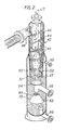
- Figure 1 is a vertical section of one embodiment of cyclone separator and Figure 2 is an elevation partly cut away of an alternative embodiment of cyclone separator.
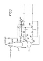
- Figure 3 is a vertical section of an alternative embodiment of cyclone separator (in which the water outlet is in a different position) and also showing schematically the oil and water level controls.
- the embodiments include the adjustable shutter to restrict the inlet as described in our UK Patent Application Nos. 2000054A and 2035150A.
- the separator indicated generally by reference numeral 2 comprises a vessel 4 having an inlet 6 of rectangular cross-section disposed tangentially with respect to the vessel 4 to cause incoming feed to form a downwardly spinning vortex of enhanced liquid from which an upwardly spinning vortex of enhanced gas separates.
- the inlet is controllably variable as described in our co-pending UK Patent Applications Nos. 2000054A and 2035150A to provide a turndown capacity and to accommodate changes in feed composition
- the separator has an outlet for gas herein referred to as a vortex finder 8 leading to an outlet pipe 10, and a hollow truncated cone 12 of small angle (the angle at the apex of the cone is 3°) to provide a surface for the downwardly spinning vortex.
- a disengaging chamber 15 is provided by the space beween cone 12 and the walls 7 of the lower part of the vessel and an outlet 20 for withdrawing gas from the disengaging chamber 15 is provided so that gas not separated from the liquid in the centrifugal action in the cone does not interfere with the liquid level control.
- the disengaging chamber 15 is also provided with a pressure relief valve 26.
- a baffle in the form of a circular plate 14, the purpose of which is to arrest the vortex of gas.
- Means are provided, (not shown), for moving the plate up or down to adjust the size of the gap between the lower end of the cone and the plate to optimise the performance of the separator.
- a first lower outlet 16 for the liquid oil arranged so that liquid is withdrawn from below the axis of the outlet to reduce the risk of entrainment of gas in the oil during discharge.
- a partition 22 in the form of a hollow truncated cone, the axis of the cone lying on the axis of the vessel.
- the cone is disposed so as to allow water to flow on its upper surface downwardly and outwardly towards the walls of the vessel and into the portion of the vessel below the partition.
- a second lower outlet 18 for the water rich liquid stream disposed in a manner similar to outlet 16.
- a set of straightening vanes, (not shown), are included in the outlet pipe 10 to eliminate any spinning of the gas.
- the vortex finder 8 has a flared portion to provide a skirt 9 to reduce the tendency of droplets of liquid on the exterior to be entrained in the gas flowing upwardly into the vortex finder.
- the vessel has two connections only one of which 28 is shown for an oil level controller, (not shown), and connections 30 and 31 for a water level controller, (also not shown). At the bottom of the vessel is a drain hole 24.
- the separator indicated generally by reference numeral 42 comprises a vessel 44 having an inlet 46 of rectangular cross-section disposed tangentially with respect to the vessel 44 to cause incoming feed to form a downwardly spinning vortex 41 from which gas separates.
- the inlet 46 is controllably variable as described in our co-pending UK Patent Applications Nos. 2000054A and 2035150A to provide a turndown capacity.
- the separator has a vortex finder 48 leading to an outlet pipe, (not shown), and a hollow inverted truncated cone of small angle 52 (the angle at the apex of the cone is 3°) to provide a surface and a downwardly spinning vortex 41.
- the ratio of the diameter of the cone 52 at its lower end to that at its upper end is 0.88.
- a set of straightening vanes, (not shown), are included in the outlet pipe, (not shown), to eliminate any spinning of the gas.
- a disengaging chamber 55 is provided by the space between cone 52 and the walls 47 of the lower part of the vessel and an outlet 60 for withdrawing gas from the disengaging chamber 55 is provided so that gas not separated from the liquid in the centrifugal action in the cone 52 does not interfere with the liquid level control.
- the disengaging chamber 55 is also provided with a pressure relief valve, (not shown).
- a baffle 54 in the form of a circular plate 54, the purpose of which is to arrest the vortex 41.
- Means are provided, (not shown), for moving the plate 54 up or down to adjust the size of the gap between the lower end of the cone 52 and the plate 54 to optimise the performance of the separator.
- a first lower outlet 56 for the liquid oil arranged so that liquid is withdrawn from below the axis of the outlet to reduce the risk of entrainment of gas in the oil during discharge.
- a deflector 62 in the form of a hollow truncated cone, the cone being coaxial with the vessel 44.
- the cone 62 is disposed so as to allow water to flow on its upper surface downwardly and outwardly towards the walls 47 of the vessel and away from the oil outlet into the portion of the vessel below the deflector.
- a second lower outlet 68 for the water rich liquid stream. Droplets of oil can flow upwards within the deflector into the oil phase above interface 70 through the aperture at the top of the cone 62.
- the vortex finder 48 has a flared portion (not shown) to provide a skirt to reduce the tendency of droplets of liquid on the exterior to be entrained in the gas flowing upwardly into the vortex finder 48.
- An oil/gas interface at 72 is normally maintained above the lower end of cone 52.
- the separator indicated generally by numeral 82 comprises a vessel 84 of similar construction to that shown in Figure 1 except the outlet 88 for the water is located nearer the base of the vessel 84.
- the vessel 84 has an oil level sensor 90 and a water level sensor 91 and control means comprising valves 93 and 94 controlling the flow in lines 95 and 96, the valves 93 and 94 being operated in response to signals indicative of the oil and water levels.
- the cyclone separator was a single vessel as illustrated in Figure 1, and was operated with the oil/gas and oil/water interfaces as shown in Figure 2.
- the liquid contained 12.0% volume of gas.
- the liquid contained 5% volume of gas.
- This Example illustrates that a separator according to the invention can separate a mixture of liquid oil with 7.2 times its own volume of gas and 16.6% its own volume of water into (i) a liquid oil containing 2% by volume of water and 12.0% by volume of gas, (ii) water containing 1.9% by volume of oil and (iii) gas containing less than 1 ppm of liquid.
- the cyclone was a single vessel as illustrated in Figure 1 but of smaller size than that employed in Example 1.
- the separator according to the present invention is particularly suitable for use as a well test separator where the mixture to be separated may be frequently contain water from drilling mud left in the well.
- references to volumes of gas and gas to liquid ratios are referred to standard conditions of temperature and pressure i.e. 14.7 psig (1013 bar absolute) and 60°F equivalent to 15.6°C.
Claims (3)
Applications Claiming Priority (2)
| Application Number | Priority Date | Filing Date | Title |
|---|---|---|---|
| GB7927806 | 1979-08-09 | ||
| GB7927806 | 1979-08-09 |
Publications (2)
| Publication Number | Publication Date |
|---|---|
| EP0024148A1 EP0024148A1 (de) | 1981-02-25 |
| EP0024148B1 true EP0024148B1 (de) | 1985-02-13 |
Family
ID=10507095
Family Applications (1)
| Application Number | Title | Priority Date | Filing Date |
|---|---|---|---|
| EP80302632A Expired EP0024148B1 (de) | 1979-08-09 | 1980-08-01 | Abscheider für Öl, Gas und Wasser |
Country Status (10)
| Country | Link |
|---|---|
| US (1) | US4428839A (de) |
| EP (1) | EP0024148B1 (de) |
| JP (1) | JPS5637065A (de) |
| AU (1) | AU538436B2 (de) |
| BR (1) | BR8005001A (de) |
| CA (1) | CA1142455A (de) |
| DE (1) | DE3070156D1 (de) |
| IN (1) | IN153070B (de) |
| MX (1) | MX154402A (de) |
| NO (1) | NO153123C (de) |
Cited By (3)
| Publication number | Priority date | Publication date | Assignee | Title |
|---|---|---|---|---|
| WO2013019522A2 (en) * | 2011-07-30 | 2013-02-07 | Services Petroliers Schlumberger | System and method for sampling multiphase fluid at a production wellsite |
| US10940492B2 (en) | 2016-07-13 | 2021-03-09 | Fosbel Wahl Holdings, Llc | Thimble for cyclone separator |
| US10987679B2 (en) | 2016-07-13 | 2021-04-27 | Fosbel Wahl Holdings, Llc | Thimble for cyclone separator |
Families Citing this family (56)
| Publication number | Priority date | Publication date | Assignee | Title |
|---|---|---|---|---|
| US4505789A (en) * | 1981-12-28 | 1985-03-19 | Olin Corporation | Dynamic gas disengaging apparatus and method for gas separation from electrolyte fluid |
| US4626237A (en) * | 1984-12-10 | 1986-12-02 | Exxon Production Research Co. | Method and apparatus for separating the components of a wellstream |
| US4617031A (en) * | 1985-02-26 | 1986-10-14 | Chevron Research Company | Hybrid double hydrocyclone-gravity gas/liquid separator |
| DE3854892T2 (de) * | 1987-11-19 | 1996-09-05 | Conoco Specialty Prod | Verfahren und vorrichtung zur phasentrennung einer mehrphasigen flüssigkeit |
| US4940473A (en) * | 1989-06-16 | 1990-07-10 | Benham Roger A | Cyclone solids separator and de-gasifier |
| US5492622A (en) * | 1990-09-28 | 1996-02-20 | Broussard; Paul C. | Water clarification apparatus |
| US5158678A (en) * | 1990-09-28 | 1992-10-27 | Broussard Paul C Sr | Water clarification method and apparatus |
| AUPM714794A0 (en) * | 1994-07-29 | 1994-08-18 | International Fluid Separation Pty Limited | Separation apparatus and method |
| US5584911A (en) * | 1995-06-15 | 1996-12-17 | Jordan Holding Company | Vapor recovery system with cyclonic separator |
| US5827357A (en) * | 1997-01-15 | 1998-10-27 | Northland Production Testing Ltd. | Separator and method for separating components of pressurized drilling fluid returns |
| CA2200825C (en) * | 1997-03-24 | 2004-07-13 | Vision Almet Limited | Moisture separator for digester gases and landfill gases and raw natural gases |
| AU757407B2 (en) * | 1997-11-18 | 2003-02-20 | Kvaerner Process Systems A.S. | Separators |
| US6238572B1 (en) | 1998-07-21 | 2001-05-29 | Clearline Systems, Inc. | Separation tank module for kitchen effluent |
| GB9822301D0 (en) * | 1998-10-14 | 1998-12-09 | Ici Plc | Level measurement systems |
| US6936230B2 (en) * | 2000-01-06 | 2005-08-30 | Viacheslav V. Zhurin | System for thermal and catalytic cracking of crude oil |
| US6269880B1 (en) | 2000-01-27 | 2001-08-07 | Ronald J. Landry | System for removing solids from a well bore |
| US6956063B2 (en) * | 2001-12-28 | 2005-10-18 | Conocophillips Company | Method for reducing water concentration in a multi-phase column reactor |
| US7001927B2 (en) * | 2001-12-28 | 2006-02-21 | Conocophillips Company | Water removal in Fischer-Tropsch processes |
| US6809122B2 (en) * | 2001-12-28 | 2004-10-26 | Conocophillips Company | Method for reducing the maximum water concentration in a multi-phase column reactor |
| GB2403440B (en) * | 2003-07-04 | 2007-09-05 | Dynamic Proc Solutions Plc | Separator |
| US7059311B2 (en) | 2004-08-12 | 2006-06-13 | Shiloh Industries, Inc. | Air/oil separating device |
| NL1029747C2 (nl) * | 2005-08-16 | 2007-02-19 | Fmc Technologies Cv | Hydrocycloon. |
| EP1779911A1 (de) * | 2005-10-28 | 2007-05-02 | M-I Epcon As | Trennungsbehälter. |
| EP1782870A1 (de) * | 2005-10-28 | 2007-05-09 | M-I Epcon As | Trennvorrichtung |
| DE102007005539B3 (de) * | 2007-02-03 | 2008-08-14 | Astrium Gmbh | Tank zur Lagerung kryogener Flüssigkeiten oder lagerfähiger flüssiger Treibstoffe |
| US20120073806A1 (en) * | 2010-09-21 | 2012-03-29 | Bp Corporation North America Inc. | Low cut water sampling device |
| US8439999B2 (en) * | 2010-10-04 | 2013-05-14 | David A. Simpson | Device for capturing gas from a produced water stream |
| US8597402B2 (en) * | 2011-09-23 | 2013-12-03 | David A. Simpson and Janet K. Simpson | Device for capturing gas from a produced water stream |
| US8961662B2 (en) * | 2011-11-23 | 2015-02-24 | Hughes Specialty Services, Inc. | Separator assembly |
| US9194196B2 (en) * | 2013-08-12 | 2015-11-24 | Canrig Drilling Technology Ltd. | Dual purpose mud-gas separator and methods |
| CA2924058C (en) | 2013-09-12 | 2022-08-30 | Thru Tubing Solutions, Inc. | Downhole gas separator |
| US9199251B1 (en) * | 2013-11-26 | 2015-12-01 | Kbk Industries, Llc | Desanding, flow splitting, degassing vessel |
| NO342254B1 (no) * | 2014-02-03 | 2018-04-30 | Dimitrije Dimitrijevic | Anordning og fremgangsmåte for utskilling av partikler fra en blanding av partikler, vann, olje og inneholdt gass |
| US9630126B1 (en) | 2014-04-15 | 2017-04-25 | Kbk Industries, Llc | High efficiency fluid separation device |
| US9863926B2 (en) * | 2014-04-22 | 2018-01-09 | Sgs North America Inc. | Condensate-gas ratios of hydrocarbon-containing fluids |
| US10640716B2 (en) | 2014-05-30 | 2020-05-05 | Fluor Technologies Corporation | Configurations and methods of dewatering crude oil |
| US9744478B1 (en) | 2014-07-22 | 2017-08-29 | Kbk Industries, Llc | Hydrodynamic water-oil separation breakthrough |
| US20160122209A1 (en) * | 2014-10-30 | 2016-05-05 | Edward G. Newman, JR. | Selective fluid retrieval and treatment system for oil and wastewater recovery |
| CN104645671B (zh) * | 2015-01-13 | 2016-03-30 | 杭州路弘科技有限公司 | 液体脱气装置及方法 |
| US9884774B1 (en) | 2015-02-04 | 2018-02-06 | Kbk Industries, Llc | Highly retentive automatically skimmable tank |
| CN104801071B (zh) * | 2015-04-14 | 2016-06-22 | 中国石油大学(华东) | 两级轴流式水下管道在线气液分离装置 |
| RU2597604C1 (ru) * | 2015-04-29 | 2016-09-10 | Открытое акционерное общество "Татнефть" имени В.Д. Шашина | Газожидкостной сепаратор |
| US10343087B2 (en) | 2015-09-18 | 2019-07-09 | R3 Oil, LLC | Recovering a hydrocarbon fluid |
| CN105419862A (zh) * | 2015-12-11 | 2016-03-23 | 淄博海润环境工程有限公司 | 一种聚结式多相旋流分离器 |
| AU2018301839B2 (en) | 2017-07-14 | 2021-07-22 | Vermeer Manufacturing Company | Hydro excavation vacuum apparatus |
| CN108579220A (zh) * | 2018-04-28 | 2018-09-28 | 上海齐耀动力技术有限公司 | 一种船用气液分离装置 |
| WO2020197888A1 (en) | 2019-03-28 | 2020-10-01 | Exxonmobil Chemical Patents Inc. | Processes and systems for converting benzene and/or toluene via methylation |
| US11643375B2 (en) | 2019-03-28 | 2023-05-09 | Exxonmobil Chemical Patents Inc. | Processes for converting benzene and/or toluene via methylation |
| US11827579B2 (en) | 2019-03-28 | 2023-11-28 | ExxonMobil Technology and Engineering Company | Processes for converting benzene and/or toluene via methylation |
| US11008521B1 (en) * | 2019-10-08 | 2021-05-18 | Saudi Arabian Oil Company | Control of demulsifier injection into crude oil entering separators |
| US10968402B1 (en) | 2019-10-08 | 2021-04-06 | Saudi Arabian Oil Company | Method and system for the control of water concentration in crude oil entering the dehydrators |
| WO2023064683A1 (en) | 2021-10-12 | 2023-04-20 | Exxonmobil Chemical Patents Inc. | Catalyst and methods for producing xylene products rich in o-xylene |
| WO2023064684A1 (en) | 2021-10-12 | 2023-04-20 | Exxonmobil Chemical Patents Inc. | Staged alkylation for producing xylene products |
| US11548784B1 (en) | 2021-10-26 | 2023-01-10 | Saudi Arabian Oil Company | Treating sulfur dioxide containing stream by acid aqueous absorption |
| US11926799B2 (en) | 2021-12-14 | 2024-03-12 | Saudi Arabian Oil Company | 2-iso-alkyl-2-(4-hydroxyphenyl)propane derivatives used as emulsion breakers for crude oil |
| WO2023218350A1 (en) * | 2022-05-12 | 2023-11-16 | Caleffi S.P.A. | Device for separating gas from a vector fluid in a circuit of a thermal system |
Citations (1)
| Publication number | Priority date | Publication date | Assignee | Title |
|---|---|---|---|---|
| GB2000054A (en) * | 1977-06-23 | 1979-01-04 | British Petroleum Co | Separating Liquid from Gas |
Family Cites Families (15)
| Publication number | Priority date | Publication date | Assignee | Title |
|---|---|---|---|---|
| US815407A (en) | 1905-06-14 | 1906-03-20 | Augustus Steiger Cooper | Separator for gas, oil, water, and sand. |
| US2387035A (en) | 1944-06-16 | 1945-10-16 | Miller Tyre | Gasoline and water separator |
| NL73070C (de) | 1950-11-14 | |||
| US2767802A (en) * | 1955-08-22 | 1956-10-23 | Shell Dev | Underwater oil precipitator |
| US3045750A (en) * | 1957-01-22 | 1962-07-24 | Us Industries Inc | Control systems |
| US3163508A (en) | 1960-09-07 | 1964-12-29 | Smith Paper Mills Ltd Howard | Method and apparatus for separating gas from liquid rich foams or liquids containing entrained air |
| US3204772A (en) | 1962-06-21 | 1965-09-07 | Pacific Pumping Company | Sand separator |
| US3273318A (en) | 1964-02-10 | 1966-09-20 | Nat Tank Co | De-sanding emulsion treater |
| GB1227128A (de) * | 1967-04-24 | 1971-04-07 | ||
| DE1301796B (de) | 1967-06-13 | 1969-08-28 | Grubbens & Co Aktiebolag | Hydrozyklon |
| US3499531A (en) | 1969-06-25 | 1970-03-10 | Ind Service Co Inc | Cyclonic separation devices |
| US3668825A (en) | 1969-08-28 | 1972-06-13 | Nat Dust Collector Corp | Method and apparatus for determining the difficulty of removing pollutants by wet scrubbing action |
| US3802570A (en) | 1972-10-25 | 1974-04-09 | M Dehne | Cyclone separator |
| US4017275A (en) | 1973-03-08 | 1977-04-12 | Maloney-Crawford Tank Corporation | Centrifugal separator |
| US4072481A (en) * | 1976-04-09 | 1978-02-07 | Laval Claude C | Device for separating multiple phase fluid systems according to the relative specific gravities of the phase |
-
1980
- 1980-08-01 EP EP80302632A patent/EP0024148B1/de not_active Expired
- 1980-08-01 DE DE8080302632T patent/DE3070156D1/de not_active Expired
- 1980-08-05 AU AU61091/80A patent/AU538436B2/en not_active Ceased
- 1980-08-06 US US06/175,405 patent/US4428839A/en not_active Expired - Lifetime
- 1980-08-07 NO NO802363A patent/NO153123C/no unknown
- 1980-08-08 IN IN907/CAL/80A patent/IN153070B/en unknown
- 1980-08-08 MX MX183515A patent/MX154402A/es unknown
- 1980-08-08 BR BR8005001A patent/BR8005001A/pt unknown
- 1980-08-08 CA CA000357892A patent/CA1142455A/en not_active Expired
- 1980-08-08 JP JP10840180A patent/JPS5637065A/ja active Pending
Patent Citations (1)
| Publication number | Priority date | Publication date | Assignee | Title |
|---|---|---|---|---|
| GB2000054A (en) * | 1977-06-23 | 1979-01-04 | British Petroleum Co | Separating Liquid from Gas |
Cited By (4)
| Publication number | Priority date | Publication date | Assignee | Title |
|---|---|---|---|---|
| WO2013019522A2 (en) * | 2011-07-30 | 2013-02-07 | Services Petroliers Schlumberger | System and method for sampling multiphase fluid at a production wellsite |
| WO2013019522A3 (en) * | 2011-07-30 | 2013-03-28 | Services Petroliers Schlumberger | System and method for sampling multiphase fluid at a production wellsite |
| US10940492B2 (en) | 2016-07-13 | 2021-03-09 | Fosbel Wahl Holdings, Llc | Thimble for cyclone separator |
| US10987679B2 (en) | 2016-07-13 | 2021-04-27 | Fosbel Wahl Holdings, Llc | Thimble for cyclone separator |
Also Published As
| Publication number | Publication date |
|---|---|
| AU6109180A (en) | 1981-02-12 |
| AU538436B2 (en) | 1984-08-16 |
| NO802363L (no) | 1981-02-10 |
| IN153070B (de) | 1984-05-26 |
| NO153123C (no) | 1986-01-22 |
| US4428839A (en) | 1984-01-31 |
| CA1142455A (en) | 1983-03-08 |
| EP0024148A1 (de) | 1981-02-25 |
| BR8005001A (pt) | 1981-02-24 |
| DE3070156D1 (en) | 1985-03-28 |
| MX154402A (es) | 1987-08-11 |
| JPS5637065A (en) | 1981-04-10 |
| NO153123B (no) | 1985-10-14 |
Similar Documents
| Publication | Publication Date | Title |
|---|---|---|
| EP0024148B1 (de) | Abscheider für Öl, Gas und Wasser | |
| EP0018168B1 (de) | Abscheider zur Trennung von Öl und Gas | |
| EP0023206B1 (de) | Trennschleuder mit tauchfluss | |
| CA2317527C (en) | Separators | |
| US4369047A (en) | Gas separation from crude oil | |
| US2664963A (en) | Gas and multiple liquid separator apparatus | |
| US4539023A (en) | Horizontal gas and liquid separator | |
| US2610697A (en) | Gas and liquid separator apparatus | |
| US20030000186A1 (en) | System for separating an entrained liquid component from a gas stream | |
| US3212232A (en) | Method and apparatus for fluid separation | |
| US6436298B1 (en) | Apparatus and method for separating a mixture of a less dense liquid and a more dense liquid | |
| NO333860B1 (no) | Innløpsanordning for gravitasjonsseparator | |
| NO316359B1 (no) | Hydroksyklon og separatorapparat | |
| GB2035150A (en) | Cyclone separator | |
| EP0041573A1 (de) | Flüssigkeitsscheider | |
| US3212234A (en) | Separation method and apparatus | |
| US3688473A (en) | Underwater oil production separator | |
| EP1125620B1 (de) | Abscheider | |
| US20210154601A1 (en) | Sand separator with gas vent | |
| RU2293595C1 (ru) | Сепаратор | |
| WO1986003252A1 (en) | Three phase separator | |
| RU2236887C1 (ru) | Сепарационная установка | |
| SU1632457A1 (ru) | Сепаратор | |
| CA2448255C (en) | A system for separating an entrained liquid component from a gas stream | |
| SU1068141A1 (ru) | Устройство дл отделени газа от жидкости |
Legal Events
| Date | Code | Title | Description |
|---|---|---|---|
| PUAI | Public reference made under article 153(3) epc to a published international application that has entered the european phase |
Free format text: ORIGINAL CODE: 0009012 |
|
| AK | Designated contracting states |
Designated state(s): DE FR GB IT NL |
|
| 17P | Request for examination filed |
Effective date: 19810624 |
|
| RAP1 | Party data changed (applicant data changed or rights of an application transferred) |
Owner name: THE BRITISH PETROLEUM COMPANY P.L.C. |
|
| ITF | It: translation for a ep patent filed |
Owner name: LENZI & C. |
|
| GRAA | (expected) grant |
Free format text: ORIGINAL CODE: 0009210 |
|
| AK | Designated contracting states |
Designated state(s): DE FR GB IT NL |
|
| REF | Corresponds to: |
Ref document number: 3070156 Country of ref document: DE Date of ref document: 19850328 |
|
| ET | Fr: translation filed | ||
| PLBE | No opposition filed within time limit |
Free format text: ORIGINAL CODE: 0009261 |
|
| STAA | Information on the status of an ep patent application or granted ep patent |
Free format text: STATUS: NO OPPOSITION FILED WITHIN TIME LIMIT |
|
| 26N | No opposition filed | ||
| PGFP | Annual fee paid to national office [announced via postgrant information from national office to epo] |
Ref country code: NL Payment date: 19870831 Year of fee payment: 8 |
|
| PG25 | Lapsed in a contracting state [announced via postgrant information from national office to epo] |
Ref country code: NL Effective date: 19890301 |
|
| NLV4 | Nl: lapsed or anulled due to non-payment of the annual fee | ||
| PG25 | Lapsed in a contracting state [announced via postgrant information from national office to epo] |
Ref country code: FR Free format text: LAPSE BECAUSE OF NON-PAYMENT OF DUE FEES Effective date: 19890428 |
|
| PG25 | Lapsed in a contracting state [announced via postgrant information from national office to epo] |
Ref country code: DE Effective date: 19890503 |
|
| REG | Reference to a national code |
Ref country code: FR Ref legal event code: ST |
|
| PGFP | Annual fee paid to national office [announced via postgrant information from national office to epo] |
Ref country code: GB Payment date: 19950710 Year of fee payment: 16 |
|
| PG25 | Lapsed in a contracting state [announced via postgrant information from national office to epo] |
Ref country code: GB Effective date: 19960801 |
|
| GBPC | Gb: european patent ceased through non-payment of renewal fee |
Effective date: 19960801 |