EP0023206B1 - Trennschleuder mit tauchfluss - Google Patents
Trennschleuder mit tauchfluss Download PDFInfo
- Publication number
- EP0023206B1 EP0023206B1 EP79901630A EP79901630A EP0023206B1 EP 0023206 B1 EP0023206 B1 EP 0023206B1 EP 79901630 A EP79901630 A EP 79901630A EP 79901630 A EP79901630 A EP 79901630A EP 0023206 B1 EP0023206 B1 EP 0023206B1
- Authority
- EP
- European Patent Office
- Prior art keywords
- chamber
- liquid
- axial tube
- gas
- bottom chamber
- Prior art date
- Legal status (The legal status is an assumption and is not a legal conclusion. Google has not performed a legal analysis and makes no representation as to the accuracy of the status listed.)
- Expired
Links
- 239000007788 liquid Substances 0.000 claims abstract description 64
- 239000000203 mixture Substances 0.000 claims abstract description 8
- 238000000926 separation method Methods 0.000 abstract description 4
- 238000009987 spinning Methods 0.000 abstract 1
- 230000002706 hydrostatic effect Effects 0.000 description 1
Images
Classifications
-
- B—PERFORMING OPERATIONS; TRANSPORTING
- B04—CENTRIFUGAL APPARATUS OR MACHINES FOR CARRYING-OUT PHYSICAL OR CHEMICAL PROCESSES
- B04C—APPARATUS USING FREE VORTEX FLOW, e.g. CYCLONES
- B04C3/00—Apparatus in which the axial direction of the vortex flow following a screw-thread type line remains unchanged ; Devices in which one of the two discharge ducts returns centrally through the vortex chamber, a reverse-flow vortex being prevented by bulkheads in the central discharge duct
- B04C3/04—Multiple arrangement thereof
-
- B—PERFORMING OPERATIONS; TRANSPORTING
- B01—PHYSICAL OR CHEMICAL PROCESSES OR APPARATUS IN GENERAL
- B01D—SEPARATION
- B01D45/00—Separating dispersed particles from gases or vapours by gravity, inertia, or centrifugal forces
- B01D45/12—Separating dispersed particles from gases or vapours by gravity, inertia, or centrifugal forces by centrifugal forces
- B01D45/16—Separating dispersed particles from gases or vapours by gravity, inertia, or centrifugal forces by centrifugal forces generated by the winding course of the gas stream, the centrifugal forces being generated solely or partly by mechanical means, e.g. fixed swirl vanes
-
- F—MECHANICAL ENGINEERING; LIGHTING; HEATING; WEAPONS; BLASTING
- F25—REFRIGERATION OR COOLING; COMBINED HEATING AND REFRIGERATION SYSTEMS; HEAT PUMP SYSTEMS; MANUFACTURE OR STORAGE OF ICE; LIQUEFACTION SOLIDIFICATION OF GASES
- F25B—REFRIGERATION MACHINES, PLANTS OR SYSTEMS; COMBINED HEATING AND REFRIGERATION SYSTEMS; HEAT PUMP SYSTEMS
- F25B2400/00—General features or devices for refrigeration machines, plants or systems, combined heating and refrigeration systems or heat-pump systems, i.e. not limited to a particular subgroup of F25B
- F25B2400/02—Centrifugal separation of gas, liquid or oil
Definitions
- This invention relates to a centrifugal separator for separating liquid from gas and having a vertically oriented cylindrical shell with a top and a bottom, a gas inlet and a gas outlet, the shell being divided by transverse walls into three chambers, a top chamber, a central chamber, and a bottom chamber, a first downcomer pipe for separated liquid from the top chamber, a second downcomer pipe for separated liquid from the central chamber to the bottom chamber, an axial tube extending from the top chamber to the bottom chamber, the axial tube formed of two parts, an upper and a lower part, spaced slightly apart to form a gap which is positioned in the upper part of the central chamber, means to impart circular flow of the liquid and gas mixture into the inlet chamber creating a vortex within the axial tube whereby liquid separated towards the outside of the chamber is drained into the lower part of the bottom chamber and entrained liquid within the vortex section travels down the axial tube when liquid therein migrates to the inside surfaces of the tube and is separated at the gap into the central chamber
- the separator of this invention distinguishes over such prior art by imparting a circular flow of the liquid and gas mixture into the top chamber, instead of the bottom chamber of the prior art.
- a majority of the gas is first separated and caused to traverse downwardly with small amounts of entrained liquid through an axial tube, while the majority of liquid present in the gas is separated and caused to traverse by means of a downcomer to a lower chamber where it may be removed.
- the gas and small amounts of entrained liquid continue to pass downwardly into contact with a cone-shaped quieting baffle the apex of which is axially below the lower end of the tube and thus further cause separation of liquid and gas which is removed from the lower chamber.
- the invention is directed to a centrifugal separator for separating liquid from gas having a vertically oriented cylindrical shell with a top and a bottom, a gas inlet and a gas outlet, the shell being divided by transverse walls into three chambers, a top chamber, a central chamber, and a bottom chamber, a first downcomer pipe for separated liquid from the top chamber, a second downcomer pipe for separated liquid from the central chamber to the bottom chamber, an axial tube extending from the top chamber to the bottom chamber, the axial tube formed of two parts, an upper and a lower part, spaced slightly apart to form a gap which is positioned in the upper part of the central chamber, means to impart circular flow of the liquid and gas mixture into the inlet chamber creating a vortex within the axial tube whereby liquid separated towards the outside of the chamber is drained into the lower part of the bottom chamber and entrained liquid within the vortex section travels down the axial tube when liquid therein migrates to the inside surfaces of the tube and is separated at the gap into the central chamber,
- the invention is particularly characterized in that said inlet means impart circular flow of the liquid and gas mixture into the top chamber so that the liquid - flowing in the same direction as the gas - is first separated to the outside of the top chamber from where it is drained directly into the bottom chamber via the first downcomer pipe, and further so that liquid being entrained in the axial tube is substantially removed via the gap into the central chamber, draining from there via the second downcomer pipe into the bottom chamber, and in that said quieting baffle means is in the form of a cone-shaped baffle, the apex of which is axially below the lower end of the axial tube, the bottom of the cone being of less diameter than the diameter of the bottom chamber, and in that said gas outlet is provided in an upper part of the bottom chamber.
- the separator further comprises: a transverse grid structure upon which the bottom of the cone rests; a transverse plate between the grid structure and the bottom of the cone; a spinner in the upper part of the axial tube; the lower part of the axial tube having a smaller internal diameter than the upper part.
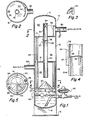
- the separator is composed of a vertically oriented cylindrical shell 12 closed at its top 14 and bottom 1 6.
- the shell is supported upon a base 18.
- the interior of the separator is divided by transverse walls 17 and 19 to form top chamber 20, central chamber 22, and bottom chamber 24.
- a first downcomer pipe 26 extends from communication with top chamber 20 into bottom chamber 24.
- a second downcomer pipe 28 extends from communication with central chamber 22 into bottom chamber 24.
- An axial tube, generally designated by the numeral 30, includes an upper portion 32 and a lower portion 34 separated in the upper part of the central chamber 22 by a gap 36.
- the axial tubing is shown having the same internal diameter, a modified form as shown in FIGURE 4 shows the lower portion 34A having a smaller internal diameter than the upper portion 32.
- Cross support members 37 retain the upper and lower portions as shown.
- a liquid level, e.g., float operated control 40 maintains a substantially constant level of separated liquid 41 in the bottom chamber, excess liquid being withdrawn by any suitable liquid removal means 42.
- the gas-liquid to be separated enters by way of conduit 50 either tangentially into chamber 20, or, as shown, using baffle 52 which imparts a circular motion to the gas-liquid.
- Spinner 54 within the upper portion 32 of the axial tube assists the vortex motion therein.
- the apex of cone 60 is positioned upon a transverse plate 62, which, in turn, is supported upon grid 64 below the outlet of the lower portion 34 of the axial tube.
- a separated gas outlet 68 is provided in the upper part of the bottom chamber 24.
- gas and entrained liquid enter conduit 50, and, deflected by baffle 52, impart a centrifugal motion to the gas liquid in top chamber 20.
- This motion forms a vortex with liquid being thrown outward where it drains from the top chamber through the first downcomer into the bottom chamber 24.
- the vortex formed by the gas may be enhanced as it enters the axial tube 30 by spinner means 34.
- the vortex in the upper portion 32 of the axial tube causes entrained liquid to migrate to the inside surface of the axial tube where it is skimmed off at the gap 36 in the central chamber 22.
- the liquid accumulating in the central chamber 22 thence travels through the second downcomer 28 into the bottom chamber 24.
- the gas continues to travel through the lower portion 34 of the axial tube existing in the bottom chamber against the cone-shaped baffle 60 where the liquid is coalesced by impingement thereagainst.
- the liquid continues to drain across the transverse plate 62 and drains into the liquid section of the bottom chamber 24.
- the grid- type support 64 under the transverse plate 62 assists in breaking up the vortex to form a quieting chamber within which the liquid level control 40 can operate to actuate removal means 42.
Landscapes
- Chemical & Material Sciences (AREA)
- Chemical Kinetics & Catalysis (AREA)
- Cyclones (AREA)
- Separating Particles In Gases By Inertia (AREA)
Claims (5)
Applications Claiming Priority (2)
| Application Number | Priority Date | Filing Date | Title |
|---|---|---|---|
| US06/004,485 US4187088A (en) | 1979-01-18 | 1979-01-18 | Down flow centrifugal separator |
| US4485 | 2001-02-11 |
Publications (3)
| Publication Number | Publication Date |
|---|---|
| EP0023206A4 EP0023206A4 (de) | 1980-12-22 |
| EP0023206A1 EP0023206A1 (de) | 1981-02-04 |
| EP0023206B1 true EP0023206B1 (de) | 1984-07-18 |
Family
ID=21711036
Family Applications (1)
| Application Number | Title | Priority Date | Filing Date |
|---|---|---|---|
| EP79901630A Expired EP0023206B1 (de) | 1979-01-18 | 1980-07-29 | Trennschleuder mit tauchfluss |
Country Status (14)
| Country | Link |
|---|---|
| US (1) | US4187088A (de) |
| EP (1) | EP0023206B1 (de) |
| JP (1) | JPS55501092A (de) |
| AR (1) | AR219838A1 (de) |
| AT (1) | AT376906B (de) |
| AU (1) | AU531799B2 (de) |
| BR (1) | BR7908977A (de) |
| CA (1) | CA1124660A (de) |
| DE (1) | DE2953483A1 (de) |
| GB (1) | GB2053033B (de) |
| IT (1) | IT1127554B (de) |
| NL (1) | NL7920154A (de) |
| RO (1) | RO84015B (de) |
| WO (1) | WO1980001466A1 (de) |
Families Citing this family (133)
| Publication number | Priority date | Publication date | Assignee | Title |
|---|---|---|---|---|
| GB2179156B (en) * | 1985-08-14 | 1990-08-22 | Ronald Northedge | Flow meters |
| US4651540A (en) * | 1986-03-21 | 1987-03-24 | Tecumseh Products Company | Suction accumulator including an entrance baffle |
| US4627247A (en) * | 1986-03-21 | 1986-12-09 | Tecumseh Products Company | Suction accumulator |
| IT1231042B (it) * | 1989-04-24 | 1991-11-12 | Ingersoll Rand Co | Separatore di olio/aria. |
| US5256171A (en) * | 1992-09-08 | 1993-10-26 | Atlantic Richfield Company | Slug flow mitigtion for production well fluid gathering system |
| US5378267A (en) * | 1993-04-06 | 1995-01-03 | Carbonair Environmental Services, Inc. | Apparatus for air stripping contaminants from water |
| US5562821A (en) * | 1995-07-21 | 1996-10-08 | Commonwealth Of Puerto Rico | Foam fractionator |
| DE69619942T2 (de) * | 1995-12-14 | 2002-12-19 | Suntec System Co Ltd | Behandlungssystem für Abgas |
| AU711476B2 (en) * | 1996-03-13 | 1999-10-14 | A P Systems (Australia) Pty Ltd | Air drying and purification system |
| AUPN865596A0 (en) * | 1996-03-13 | 1996-04-04 | Bellomo, Erasmo Mimmo | Air drying and purification system |
| JP3268298B2 (ja) * | 1997-07-07 | 2002-03-25 | 株式会社カマタテクナス | 高圧空気の除湿装置 |
| US5931990A (en) * | 1997-12-03 | 1999-08-03 | Coronator | Tank for removing unabsorbed gas from a mixture of unabsorbed gas and liquid |
| US6062039A (en) * | 1998-01-07 | 2000-05-16 | Parker-Hannifin Corporation | Universal accumulator for automobile air conditioning systems |
| NL1012245C2 (nl) | 1999-06-04 | 2000-12-06 | Spark Technologies And Innovat | Inrichting en werkwijze voor het verwerken van een mengsel van gas met vloeistof en/of vaste stof. |
| US6251296B1 (en) | 1999-07-27 | 2001-06-26 | G.B.D. Corp. | Apparatus and method for separating particles from a cyclonic fluid flow |
| US6440197B1 (en) * | 1999-07-27 | 2002-08-27 | G.B.D. Corp. | Apparatus and method separating particles from a cyclonic fluid flow including an apertured particle separation member within a cyclonic flow region |
| US6231645B1 (en) | 1999-07-27 | 2001-05-15 | G.B.D. Corp. | Apparatus and method for separating particles from a cyclonic fluid flow utilizing a movable access member associated with a cyclonic separator |
| US6221134B1 (en) | 1999-07-27 | 2001-04-24 | G.B.D. Corp. | Apparatus and method for separating particles from a cyclonic fluid flow |
| US6228260B1 (en) | 1999-07-27 | 2001-05-08 | G. B. D. Corp. | Apparatus for separating particles from a cyclonic fluid flow |
| US6228151B1 (en) | 1999-08-18 | 2001-05-08 | G.B.D. Corp. | Apparatus and method for separating particles from a cyclonic fluid flow |
| DE19961550A1 (de) * | 1999-12-20 | 2001-06-28 | Reinz Dichtungs Gmbh | Vorrichtung und Verfahren zur Nebelabscheidung sowie Verwendung der Vorrichtung |
| JP4906175B2 (ja) * | 2000-03-24 | 2012-03-28 | 株式会社カマタテクナス | 気液分離装置 |
| US20050172808A1 (en) * | 2002-12-09 | 2005-08-11 | Ye Yi | Method and apparatus for removing VOCs from water |
| US6878188B2 (en) * | 2002-12-09 | 2005-04-12 | Ye Yi | Method and apparatus for removing VOCs from water |
| US7481871B2 (en) * | 2004-12-10 | 2009-01-27 | Exxonmobil Chemical Patents Inc. | Vapor/liquid separation apparatus |
| US7803207B2 (en) * | 2006-03-10 | 2010-09-28 | G.B.D. Corp. | Vacuum cleaner with a divider |
| US8950039B2 (en) | 2009-03-11 | 2015-02-10 | G.B.D. Corp. | Configuration of a surface cleaning apparatus |
| US10765277B2 (en) | 2006-12-12 | 2020-09-08 | Omachron Intellectual Property Inc. | Configuration of a surface cleaning apparatus |
| CA2599303A1 (en) | 2007-08-29 | 2009-02-28 | Gbd Corp. | Surface cleaning apparatus |
| GB2457420B (en) | 2006-12-12 | 2012-01-04 | Gbd Corp | Convertible surface cleaning apparatus |
| US9301666B2 (en) | 2006-12-12 | 2016-04-05 | Omachron Intellectual Property Inc. | Surface cleaning apparatus |
| US8146201B2 (en) * | 2006-12-12 | 2012-04-03 | G.B.D. Corp. | Surface cleaning apparatus |
| US9888817B2 (en) | 2014-12-17 | 2018-02-13 | Omachron Intellectual Property Inc. | Surface cleaning apparatus |
| US20210401246A1 (en) | 2016-04-11 | 2021-12-30 | Omachron Intellectual Property Inc. | Surface cleaning apparatus |
| US20080172992A1 (en) * | 2006-12-15 | 2008-07-24 | G.B.D. Corp. | Vacuum cleaner with openable lid |
| US11857142B2 (en) | 2006-12-15 | 2024-01-02 | Omachron Intellectual Property Inc. | Surface cleaning apparatus having an energy storage member and a charger for an energy storage member |
| US9192269B2 (en) | 2006-12-15 | 2015-11-24 | Omachron Intellectual Property Inc. | Surface cleaning apparatus |
| US10165912B2 (en) | 2006-12-15 | 2019-01-01 | Omachron Intellectual Property Inc. | Surface cleaning apparatus |
| US11751733B2 (en) | 2007-08-29 | 2023-09-12 | Omachron Intellectual Property Inc. | Portable surface cleaning apparatus |
| US9265395B2 (en) | 2010-03-12 | 2016-02-23 | Omachron Intellectual Property Inc. | Surface cleaning apparatus |
| US9198551B2 (en) | 2013-02-28 | 2015-12-01 | Omachron Intellectual Property Inc. | Surface cleaning apparatus |
| US9480373B2 (en) | 2009-03-13 | 2016-11-01 | Omachron Intellectual Property Inc. | Surface cleaning apparatus |
| CA2674376A1 (en) | 2009-03-13 | 2010-09-13 | G.B.D. Corp. | Surface cleaning apparatus with different cleaning configurations |
| US11612288B2 (en) | 2009-03-13 | 2023-03-28 | Omachron Intellectual Property Inc. | Surface cleaning apparatus |
| US9427122B2 (en) | 2009-03-13 | 2016-08-30 | Omachron Intellectual Property Inc. | Surface cleaning apparatus |
| US9392916B2 (en) | 2009-03-13 | 2016-07-19 | Omachron Intellectual Property Inc. | Surface cleaning apparatus |
| US9211044B2 (en) | 2011-03-04 | 2015-12-15 | Omachron Intellectual Property Inc. | Compact surface cleaning apparatus |
| US11690489B2 (en) | 2009-03-13 | 2023-07-04 | Omachron Intellectual Property Inc. | Surface cleaning apparatus with an external dirt chamber |
| CA2674761C (en) | 2009-03-13 | 2016-10-04 | G.B.D. Corp. | Surface cleaning apparatus with different cleaning configurations |
| CA2967272C (en) | 2009-03-13 | 2018-01-02 | Omachron Intellectual Property Inc. | Hand vacuum cleaner |
| US9138114B2 (en) | 2009-03-13 | 2015-09-22 | Omachron Intellectual Property Inc. | Surface cleaning apparatus |
| US9433332B2 (en) | 2013-02-27 | 2016-09-06 | Omachron Intellectual Property Inc. | Surface cleaning apparatus |
| US10722086B2 (en) | 2017-07-06 | 2020-07-28 | Omachron Intellectual Property Inc. | Handheld surface cleaning apparatus |
| US9226633B2 (en) | 2009-03-13 | 2016-01-05 | Omachron Intellectual Property Inc. | Surface cleaning apparatus |
| US9591953B2 (en) | 2009-03-13 | 2017-03-14 | Omachron Intellectual Property Inc. | Surface cleaning apparatus |
| US7785400B1 (en) | 2009-06-30 | 2010-08-31 | Sand Separators LLC | Spherical sand separators |
| JP4695215B1 (ja) | 2010-03-05 | 2011-06-08 | 独立行政法人石油天然ガス・金属鉱物資源機構 | 気液分離器及び流量計測装置 |
| US8640304B2 (en) | 2010-03-12 | 2014-02-04 | G.B.D. Corp. | Cyclone construction for a surface cleaning apparatus |
| US8875340B2 (en) | 2010-03-12 | 2014-11-04 | G.B.D. Corp. | Surface cleaning apparatus with enhanced operability |
| JP4688974B1 (ja) | 2010-12-13 | 2011-05-25 | 独立行政法人石油天然ガス・金属鉱物資源機構 | バッチ式多相流量測定装置及び流量計測方法 |
| MX352243B (es) | 2012-01-03 | 2017-11-15 | Exxonmobil Upstream Res Co | Metodo para produccion de hidrocarburos que usa cavernas. |
| AU2013293508B2 (en) * | 2012-07-27 | 2016-04-14 | Exxonmobil Upstream Research Company | Multiphase separation system |
| US9371724B2 (en) | 2012-07-27 | 2016-06-21 | Exxonmobil Upstream Research Company | Multiphase separation system |
| GB2508657A (en) * | 2012-12-10 | 2014-06-11 | Linde Ag | Vertical degasser |
| US9320401B2 (en) | 2013-02-27 | 2016-04-26 | Omachron Intellectual Property Inc. | Surface cleaning apparatus |
| US9027198B2 (en) | 2013-02-27 | 2015-05-12 | G.B.D. Corp. | Surface cleaning apparatus |
| US9591958B2 (en) | 2013-02-27 | 2017-03-14 | Omachron Intellectual Property Inc. | Surface cleaning apparatus |
| US9820621B2 (en) | 2013-02-28 | 2017-11-21 | Omachron Intellectual Property Inc. | Surface cleaning apparatus |
| US9456721B2 (en) | 2013-02-28 | 2016-10-04 | Omachron Intellectual Property Inc. | Surface cleaning apparatus |
| US9295995B2 (en) | 2013-02-28 | 2016-03-29 | Omachron Intellectual Property Inc. | Cyclone such as for use in a surface cleaning apparatus |
| US9427126B2 (en) | 2013-03-01 | 2016-08-30 | Omachron Intellectual Property Inc. | Surface cleaning apparatus |
| US9364127B2 (en) | 2013-02-28 | 2016-06-14 | Omachron Intellectual Property Inc. | Surface cleaning apparatus |
| US9204773B2 (en) | 2013-03-01 | 2015-12-08 | Omachron Intellectual Property Inc. | Surface cleaning apparatus |
| US9314138B2 (en) | 2013-02-28 | 2016-04-19 | Omachron Intellectual Property Inc. | Surface cleaning apparatus |
| US9451855B2 (en) | 2013-02-28 | 2016-09-27 | Omachron Intellectual Property Inc. | Surface cleaning apparatus |
| US9326652B2 (en) | 2013-02-28 | 2016-05-03 | Omachron Intellectual Property Inc. | Surface cleaning apparatus |
| US9227201B2 (en) | 2013-02-28 | 2016-01-05 | Omachron Intellectual Property Inc. | Cyclone such as for use in a surface cleaning apparatus |
| US20140237764A1 (en) | 2013-02-28 | 2014-08-28 | G.B.D. Corp. | Cyclone such as for use in a surface cleaning apparatus |
| US9215960B2 (en) | 2013-02-28 | 2015-12-22 | Omachron Intellectual Property Inc. | Surface cleaning apparatus |
| US9161669B2 (en) | 2013-03-01 | 2015-10-20 | Omachron Intellectual Property Inc. | Surface cleaning apparatus |
| US9238235B2 (en) | 2013-02-28 | 2016-01-19 | Omachron Intellectual Property Inc. | Cyclone such as for use in a surface cleaning apparatus |
| US9227151B2 (en) | 2013-02-28 | 2016-01-05 | Omachron Intellectual Property Inc. | Cyclone such as for use in a surface cleaning apparatus |
| BR112016019671B1 (pt) | 2014-03-12 | 2020-01-07 | Exxonmobil Upstream Research Company | Sistema de separação multifásico submarino e método para a separação de óleo, água, e partículas sólidas em um fluido multifásico |
| WO2015167778A2 (en) | 2014-04-29 | 2015-11-05 | Exxonmobil Upstream Research Company | Multiphase separation system |
| US9314139B2 (en) | 2014-07-18 | 2016-04-19 | Omachron Intellectual Property Inc. | Portable surface cleaning apparatus |
| US9420925B2 (en) | 2014-07-18 | 2016-08-23 | Omachron Intellectual Property Inc. | Portable surface cleaning apparatus |
| US9585530B2 (en) | 2014-07-18 | 2017-03-07 | Omachron Intellectual Property Inc. | Portable surface cleaning apparatus |
| US9451853B2 (en) | 2014-07-18 | 2016-09-27 | Omachron Intellectual Property Inc. | Portable surface cleaning apparatus |
| US10046251B2 (en) | 2014-11-17 | 2018-08-14 | Exxonmobil Upstream Research Company | Liquid collection system |
| US10136778B2 (en) | 2014-12-17 | 2018-11-27 | Omachron Intellectual Property Inc. | Surface cleaning apparatus |
| US10251519B2 (en) | 2014-12-17 | 2019-04-09 | Omachron Intellectual Property Inc. | Surface cleaning apparatus |
| US11950745B2 (en) | 2014-12-17 | 2024-04-09 | Omachron Intellectual Property Inc. | Surface cleaning apparatus |
| US10792604B2 (en) * | 2015-06-25 | 2020-10-06 | Tm Industrial Supply, Inc. | Horizontal coalescing filter |
| WO2017000062A1 (en) | 2015-06-29 | 2017-01-05 | SegreTECH Inc. | Method and apparatus for removal of sand from gas |
| US10258210B2 (en) | 2016-12-27 | 2019-04-16 | Omachron Intellectual Property Inc. | Multistage cyclone and surface cleaning apparatus having same |
| US10136779B2 (en) | 2016-08-29 | 2018-11-27 | Omachron Intellectual Property Inc. | Surface cleaning apparatus |
| US10413141B2 (en) | 2016-08-29 | 2019-09-17 | Omachron Intellectual Property Inc. | Surface cleaning apparatus |
| US10441124B2 (en) | 2016-08-29 | 2019-10-15 | Omachron Intellectual Property Inc. | Surface cleaning apparatus |
| US10441125B2 (en) | 2016-08-29 | 2019-10-15 | Omachron Intellectual Property Inc. | Surface cleaning apparatus |
| US10433689B2 (en) | 2016-08-29 | 2019-10-08 | Omachron Intellectual Property Inc. | Surface cleaning apparatus |
| US9962050B2 (en) | 2016-08-29 | 2018-05-08 | Omachron Intellectual Property Inc. | Surface cleaning apparatus |
| US10292550B2 (en) | 2016-08-29 | 2019-05-21 | Omachron Intellectual Property Inc. | Surface cleaning apparatus |
| US10321794B2 (en) | 2016-08-29 | 2019-06-18 | Omachron Intellectual Property Inc. | Surface cleaning apparatus |
| US10729295B2 (en) | 2016-08-29 | 2020-08-04 | Omachron Intellectual Property Inc. | Surface cleaning apparatus |
| US10405711B2 (en) | 2016-08-29 | 2019-09-10 | Omachron Intellectual Property Inc. | Surface cleaning apparatus |
| US11478117B2 (en) | 2016-08-29 | 2022-10-25 | Omachron Intellectual Property Inc. | Surface cleaning apparatus |
| US10136780B2 (en) | 2016-08-29 | 2018-11-27 | Omachron Intellectual Property Inc. | Surface cleaning apparatus |
| US10827891B2 (en) | 2016-12-27 | 2020-11-10 | Omachron Intellectual Property Inc. | Multistage cyclone and surface cleaning apparatus having same |
| US10016106B1 (en) | 2016-12-27 | 2018-07-10 | Omachron Intellectual Property Inc. | Multistage cyclone and surface cleaning apparatus having same |
| US10299643B2 (en) | 2016-12-27 | 2019-05-28 | Omachron Intellectual Property Inc. | Multistage cyclone and surface cleaning apparatus having same |
| US10405709B2 (en) | 2016-12-27 | 2019-09-10 | Omachron Intellectual Property Inc. | Multistage cyclone and surface cleaning apparatus having same |
| US10271704B2 (en) | 2016-12-27 | 2019-04-30 | Omachron Intellectual Property Inc. | Multistage cyclone and surface cleaning apparatus having same |
| US11285495B2 (en) | 2016-12-27 | 2022-03-29 | Omachron Intellectual Property Inc. | Multistage cyclone and surface cleaning apparatus having same |
| US10631693B2 (en) | 2017-07-06 | 2020-04-28 | Omachron Intellectual Property Inc. | Handheld surface cleaning apparatus |
| US11766156B2 (en) | 2020-03-18 | 2023-09-26 | Omachron Intellectual Property Inc. | Surface cleaning apparatus with removable air treatment member assembly |
| US11445878B2 (en) | 2020-03-18 | 2022-09-20 | Omachron Intellectual Property Inc. | Surface cleaning apparatus with removable air treatment member assembly |
| US10702113B2 (en) | 2017-07-06 | 2020-07-07 | Omachron Intellectual Property Inc. | Handheld surface cleaning apparatus |
| US10537216B2 (en) | 2017-07-06 | 2020-01-21 | Omachron Intellectual Property Inc. | Handheld surface cleaning apparatus |
| US11666193B2 (en) | 2020-03-18 | 2023-06-06 | Omachron Intellectual Property Inc. | Surface cleaning apparatus with removable air treatment member assembly |
| US11730327B2 (en) | 2020-03-18 | 2023-08-22 | Omachron Intellectual Property Inc. | Surface cleaning apparatus with removable air treatment assembly |
| US10842330B2 (en) | 2017-07-06 | 2020-11-24 | Omachron Intellectual Property Inc. | Handheld surface cleaning apparatus |
| US10750913B2 (en) | 2017-07-06 | 2020-08-25 | Omachron Intellectual Property Inc. | Handheld surface cleaning apparatus |
| US10506904B2 (en) | 2017-07-06 | 2019-12-17 | Omachron Intellectual Property Inc. | Handheld surface cleaning apparatus |
| WO2019112755A1 (en) * | 2017-12-06 | 2019-06-13 | Cummins Filtration Ip, Inc. | Crankcase ventilation systems having a swirl breaker to reduce pressure drop in tangentially exiting fluids |
| US11013378B2 (en) | 2018-04-20 | 2021-05-25 | Omachon Intellectual Property Inc. | Surface cleaning apparatus |
| US10711589B2 (en) | 2018-08-08 | 2020-07-14 | A.S.A.P. Industries Manufacturing, Inc. | Sand separator |
| US11013384B2 (en) | 2018-08-13 | 2021-05-25 | Omachron Intellectual Property Inc. | Cyclonic air treatment member and surface cleaning apparatus including the same |
| US11192122B2 (en) | 2018-08-13 | 2021-12-07 | Omachron Intellectual Property Inc. | Cyclonic air treatment member and surface cleaning apparatus including the same |
| US11006799B2 (en) | 2018-08-13 | 2021-05-18 | Omachron Intellectual Property Inc. | Cyclonic air treatment member and surface cleaning apparatus including the same |
| US10717026B1 (en) | 2019-02-28 | 2020-07-21 | Covenant Testing Technology, LLC | Well production separation systems and methods |
| US11530944B1 (en) | 2019-02-28 | 2022-12-20 | Covenant Testing Technologies, Llc | Well fluid management systems and methods |
| US11751740B2 (en) | 2019-11-18 | 2023-09-12 | Omachron Intellectual Property Inc. | Multi-inlet cyclone |
| US11246462B2 (en) | 2019-11-18 | 2022-02-15 | Omachron Intellectual Property Inc. | Multi-inlet cyclone |
Citations (6)
| Publication number | Priority date | Publication date | Assignee | Title |
|---|---|---|---|---|
| US2493095A (en) * | 1946-07-25 | 1950-01-03 | Elmer R Williams | Oil and gas separator |
| DE1938378A1 (de) * | 1968-07-30 | 1970-02-05 | Fuller Co | Vorrichtung zum Nassreinigen von Gas mit einem Mitnahme-Separator |
| DE2612688A1 (de) * | 1976-01-15 | 1977-07-21 | Fioratti | Universalzentrifugalfilter zum faellen von staub, tropfen und nebel und zur eventuellen reinigung von giftigen gasen |
| FR2394329A1 (fr) * | 1977-06-13 | 1979-01-12 | Perry Equipment Corp | Separateur de phases gaz-particules avec dispositif de separation du gaz de balayage |
| EP0002235A1 (de) * | 1977-11-30 | 1979-06-13 | STEIN INDUSTRIE Société anonyme dite: | Senkrechter Abscheider für eine Dampfflüssigkeitsmischung |
| FR2425272A1 (fr) * | 1978-05-12 | 1979-12-07 | Stein Industrie | Separateur vertical d'un melange de vapeur ou de gaz et de particules liquides ou solides |
Family Cites Families (13)
| Publication number | Priority date | Publication date | Assignee | Title |
|---|---|---|---|---|
| US1923598A (en) * | 1931-07-16 | 1933-08-22 | Jay P Walker | Separator |
| US1923599A (en) * | 1931-08-31 | 1933-08-22 | Jay P Walker | Separator |
| US2016641A (en) * | 1933-09-15 | 1935-10-08 | Lincoln Abe | Oil and gas separator |
| US2353833A (en) * | 1941-07-28 | 1944-07-18 | Garman O Kimmell | Separator for treating foamy oil |
| US2692026A (en) * | 1950-11-13 | 1954-10-19 | Apex Electrical Mfg Co | Self-unloading centrifugal separator |
| US2678699A (en) * | 1952-02-18 | 1954-05-18 | Superior Tank & Construction C | Oil and gas separator |
| US3021709A (en) * | 1958-02-24 | 1962-02-20 | Nat Tank Co | Methods and means for separating liquids from petroleum streams and metering the separated liquids |
| US2952330A (en) * | 1958-03-12 | 1960-09-13 | Charles A Winslow | Centrifugal-type fluid purifier |
| US3306007A (en) * | 1964-02-19 | 1967-02-28 | Clarence O Glasgow | Apparatus for separating oil and gas fluid streams |
| GB1227128A (de) * | 1967-04-24 | 1971-04-07 | ||
| US4017275A (en) * | 1973-03-08 | 1977-04-12 | Maloney-Crawford Tank Corporation | Centrifugal separator |
| US3877904A (en) * | 1974-06-18 | 1975-04-15 | Combustion Eng | Gas-liquid separator |
| DE2650411A1 (de) * | 1976-11-03 | 1978-05-18 | Maloney Crawford Tank | Zentrifugalabscheider zur trennung von fluessigkeiten und gasen und verfahren zum trennen eines fluessigkeit- gasgemisches |
-
1979
- 1979-01-18 US US06/004,485 patent/US4187088A/en not_active Expired - Lifetime
- 1979-10-17 AU AU51857/79A patent/AU531799B2/en not_active Ceased
- 1979-10-24 JP JP50208079A patent/JPS55501092A/ja active Pending
- 1979-10-24 DE DE792953483T patent/DE2953483A1/de not_active Withdrawn
- 1979-10-24 GB GB8027197A patent/GB2053033B/en not_active Expired
- 1979-10-24 BR BR7908977A patent/BR7908977A/pt unknown
- 1979-10-24 AT AT0906779A patent/AT376906B/de not_active IP Right Cessation
- 1979-10-24 NL NL7920154A patent/NL7920154A/nl unknown
- 1979-10-24 WO PCT/US1979/000889 patent/WO1980001466A1/en unknown
- 1979-10-30 CA CA338,709A patent/CA1124660A/en not_active Expired
- 1979-11-12 AR AR278856A patent/AR219838A1/es active
-
1980
- 1980-01-16 IT IT47612/80A patent/IT1127554B/it active
- 1980-07-29 EP EP79901630A patent/EP0023206B1/de not_active Expired
- 1980-08-25 RO RO102039A patent/RO84015B/ro unknown
Patent Citations (6)
| Publication number | Priority date | Publication date | Assignee | Title |
|---|---|---|---|---|
| US2493095A (en) * | 1946-07-25 | 1950-01-03 | Elmer R Williams | Oil and gas separator |
| DE1938378A1 (de) * | 1968-07-30 | 1970-02-05 | Fuller Co | Vorrichtung zum Nassreinigen von Gas mit einem Mitnahme-Separator |
| DE2612688A1 (de) * | 1976-01-15 | 1977-07-21 | Fioratti | Universalzentrifugalfilter zum faellen von staub, tropfen und nebel und zur eventuellen reinigung von giftigen gasen |
| FR2394329A1 (fr) * | 1977-06-13 | 1979-01-12 | Perry Equipment Corp | Separateur de phases gaz-particules avec dispositif de separation du gaz de balayage |
| EP0002235A1 (de) * | 1977-11-30 | 1979-06-13 | STEIN INDUSTRIE Société anonyme dite: | Senkrechter Abscheider für eine Dampfflüssigkeitsmischung |
| FR2425272A1 (fr) * | 1978-05-12 | 1979-12-07 | Stein Industrie | Separateur vertical d'un melange de vapeur ou de gaz et de particules liquides ou solides |
Also Published As
| Publication number | Publication date |
|---|---|
| JPS55501092A (de) | 1980-12-11 |
| WO1980001466A1 (en) | 1980-07-24 |
| EP0023206A4 (de) | 1980-12-22 |
| IT8047612A0 (it) | 1980-01-16 |
| RO84015A (ro) | 1984-05-12 |
| IT1127554B (it) | 1986-05-21 |
| ATA906779A (de) | 1984-06-15 |
| DE2953483A1 (de) | 1981-01-29 |
| AU5185779A (en) | 1980-07-24 |
| BR7908977A (pt) | 1981-06-30 |
| EP0023206A1 (de) | 1981-02-04 |
| AU531799B2 (en) | 1983-09-08 |
| GB2053033B (en) | 1982-11-17 |
| AR219838A1 (es) | 1980-09-15 |
| AT376906B (de) | 1985-01-25 |
| GB2053033A (en) | 1981-02-04 |
| US4187088A (en) | 1980-02-05 |
| CA1124660A (en) | 1982-06-01 |
| NL7920154A (de) | 1980-11-28 |
| RO84015B (ro) | 1984-06-30 |
Similar Documents
| Publication | Publication Date | Title |
|---|---|---|
| EP0023206B1 (de) | Trennschleuder mit tauchfluss | |
| EP0024148B1 (de) | Abscheider für Öl, Gas und Wasser | |
| US4015960A (en) | Centrifugal separator for separating entrained liquid from a stream of liquid-bearing gases | |
| US20190030546A1 (en) | Inlet Device For Gravity Separator | |
| US4668256A (en) | Liquid/gas separation | |
| US4778494A (en) | Cyclone inlet flow diverter for separator vessels | |
| EP0195464B1 (de) | Kolonne zur Entfernung einer Flüssigkeit aus einem Gas | |
| US3212232A (en) | Method and apparatus for fluid separation | |
| US4187089A (en) | Horizontal vapor-liquid separator | |
| SE500478C2 (sv) | Förfarande och anordning för rening av gas | |
| US3212234A (en) | Separation method and apparatus | |
| US3457703A (en) | Method and apparatus for separating water-hydrocarbon mixtures | |
| US5073266A (en) | Apparatus for separating commingling heavier and lighter immiscible | |
| CA1046428A (en) | Vapor-liquid separator and method | |
| EP0331247B1 (de) | Gas-/Flüssigkeit-Kontaktvorrichtung | |
| US2756837A (en) | Liquid and gas separator | |
| US4483697A (en) | Compact gas liquid separator | |
| US2353833A (en) | Separator for treating foamy oil | |
| US3483678A (en) | Apparatus for removing suspended particles from gases | |
| US20020162806A1 (en) | Inclined free water knockout (IFWKO) | |
| WO1981001110A1 (en) | Horizontal vapor-liquid separator | |
| RU2293595C1 (ru) | Сепаратор | |
| US3826064A (en) | Vapor-liquid separator | |
| US4689158A (en) | Decanting device for separation of phases of different densities | |
| SU719672A1 (ru) | Циклонный сепаратор жидкости |
Legal Events
| Date | Code | Title | Description |
|---|---|---|---|
| PUAI | Public reference made under article 153(3) epc to a published international application that has entered the european phase |
Free format text: ORIGINAL CODE: 0009012 |
|
| AK | Designated contracting states |
Designated state(s): FR |
|
| 17P | Request for examination filed |
Effective date: 19801125 |
|
| GRAA | (expected) grant |
Free format text: ORIGINAL CODE: 0009210 |
|
| AK | Designated contracting states |
Designated state(s): FR |
|
| ET | Fr: translation filed | ||
| PGFP | Annual fee paid to national office [announced via postgrant information from national office to epo] |
Ref country code: FR Payment date: 19841030 Year of fee payment: 6 |
|
| PLBE | No opposition filed within time limit |
Free format text: ORIGINAL CODE: 0009261 |
|
| STAA | Information on the status of an ep patent application or granted ep patent |
Free format text: STATUS: NO OPPOSITION FILED WITHIN TIME LIMIT |
|
| 26N | No opposition filed | ||
| PG25 | Lapsed in a contracting state [announced via postgrant information from national office to epo] |
Ref country code: FR Free format text: LAPSE BECAUSE OF NON-PAYMENT OF DUE FEES Effective date: 19860630 |
|
| REG | Reference to a national code |
Ref country code: FR Ref legal event code: ST |