EP4397993A2 - Verfahren und system zur doppler-detektion und doppler-korrektur der detektion eines optischen phasencodierten bereichs - Google Patents
Verfahren und system zur doppler-detektion und doppler-korrektur der detektion eines optischen phasencodierten bereichs Download PDFInfo
- Publication number
- EP4397993A2 EP4397993A2 EP24177690.5A EP24177690A EP4397993A2 EP 4397993 A2 EP4397993 A2 EP 4397993A2 EP 24177690 A EP24177690 A EP 24177690A EP 4397993 A2 EP4397993 A2 EP 4397993A2
- Authority
- EP
- European Patent Office
- Prior art keywords
- signal
- phase
- optical signal
- returned
- optical
- Prior art date
- Legal status (The legal status is an assumption and is not a legal conclusion. Google has not performed a legal analysis and makes no representation as to the accuracy of the status listed.)
- Pending
Links
- 230000003287 optical effect Effects 0.000 title claims abstract description 318
- 238000000034 method Methods 0.000 title claims abstract description 61
- 238000001514 detection method Methods 0.000 title claims abstract description 33
- 238000012937 correction Methods 0.000 title description 15
- 238000012545 processing Methods 0.000 claims abstract description 23
- 230000004044 response Effects 0.000 claims abstract description 13
- 238000001228 spectrum Methods 0.000 claims description 65
- 238000002156 mixing Methods 0.000 claims description 18
- 230000035559 beat frequency Effects 0.000 claims description 9
- 238000004891 communication Methods 0.000 description 23
- 230000000694 effects Effects 0.000 description 19
- 230000006870 function Effects 0.000 description 19
- 238000012935 Averaging Methods 0.000 description 15
- 238000013459 approach Methods 0.000 description 13
- 230000008901 benefit Effects 0.000 description 12
- 230000000875 corresponding effect Effects 0.000 description 11
- 238000010586 diagram Methods 0.000 description 11
- 238000005259 measurement Methods 0.000 description 11
- 238000003860 storage Methods 0.000 description 11
- 230000008569 process Effects 0.000 description 10
- 230000005540 biological transmission Effects 0.000 description 6
- 230000001427 coherent effect Effects 0.000 description 6
- 230000005684 electric field Effects 0.000 description 6
- 239000000835 fiber Substances 0.000 description 5
- 239000013078 crystal Substances 0.000 description 4
- 238000000926 separation method Methods 0.000 description 4
- 230000007480 spreading Effects 0.000 description 4
- 238000003892 spreading Methods 0.000 description 4
- 238000003491 array Methods 0.000 description 3
- 238000004364 calculation method Methods 0.000 description 3
- 230000008878 coupling Effects 0.000 description 3
- 238000010168 coupling process Methods 0.000 description 3
- 238000005859 coupling reaction Methods 0.000 description 3
- 230000009467 reduction Effects 0.000 description 3
- 230000003068 static effect Effects 0.000 description 3
- 238000004422 calculation algorithm Methods 0.000 description 2
- 238000012512 characterization method Methods 0.000 description 2
- 238000001914 filtration Methods 0.000 description 2
- 238000003384 imaging method Methods 0.000 description 2
- 230000003993 interaction Effects 0.000 description 2
- GQYHUHYESMUTHG-UHFFFAOYSA-N lithium niobate Chemical compound [Li+].[O-][Nb](=O)=O GQYHUHYESMUTHG-UHFFFAOYSA-N 0.000 description 2
- 238000013507 mapping Methods 0.000 description 2
- 230000007246 mechanism Effects 0.000 description 2
- 238000012986 modification Methods 0.000 description 2
- 230000004048 modification Effects 0.000 description 2
- 230000010363 phase shift Effects 0.000 description 2
- 230000010287 polarization Effects 0.000 description 2
- 239000002096 quantum dot Substances 0.000 description 2
- 239000007787 solid Substances 0.000 description 2
- 230000003595 spectral effect Effects 0.000 description 2
- HPTJABJPZMULFH-UHFFFAOYSA-N 12-[(Cyclohexylcarbamoyl)amino]dodecanoic acid Chemical compound OC(=O)CCCCCCCCCCCNC(=O)NC1CCCCC1 HPTJABJPZMULFH-UHFFFAOYSA-N 0.000 description 1
- RYGMFSIKBFXOCR-UHFFFAOYSA-N Copper Chemical compound [Cu] RYGMFSIKBFXOCR-UHFFFAOYSA-N 0.000 description 1
- 241001272996 Polyphylla fullo Species 0.000 description 1
- 239000000654 additive Substances 0.000 description 1
- 230000000996 additive effect Effects 0.000 description 1
- 239000003570 air Substances 0.000 description 1
- 230000004075 alteration Effects 0.000 description 1
- 230000003321 amplification Effects 0.000 description 1
- 238000010009 beating Methods 0.000 description 1
- 230000015556 catabolic process Effects 0.000 description 1
- 230000008859 change Effects 0.000 description 1
- 239000002131 composite material Substances 0.000 description 1
- 239000004020 conductor Substances 0.000 description 1
- 230000001276 controlling effect Effects 0.000 description 1
- 230000002596 correlated effect Effects 0.000 description 1
- 230000007123 defense Effects 0.000 description 1
- 238000006731 degradation reaction Methods 0.000 description 1
- 230000003292 diminished effect Effects 0.000 description 1
- 238000004870 electrical engineering Methods 0.000 description 1
- 238000005516 engineering process Methods 0.000 description 1
- 230000007717 exclusion Effects 0.000 description 1
- 210000003918 fraction a Anatomy 0.000 description 1
- 239000011521 glass Substances 0.000 description 1
- 238000002955 isolation Methods 0.000 description 1
- 239000004973 liquid crystal related substance Substances 0.000 description 1
- 238000004519 manufacturing process Methods 0.000 description 1
- 239000000463 material Substances 0.000 description 1
- 238000007620 mathematical function Methods 0.000 description 1
- 229910052751 metal Inorganic materials 0.000 description 1
- 239000002184 metal Substances 0.000 description 1
- 230000001343 mnemonic effect Effects 0.000 description 1
- 238000003199 nucleic acid amplification method Methods 0.000 description 1
- 239000013307 optical fiber Substances 0.000 description 1
- 238000005457 optimization Methods 0.000 description 1
- 230000010355 oscillation Effects 0.000 description 1
- 230000002085 persistent effect Effects 0.000 description 1
- 230000000704 physical effect Effects 0.000 description 1
- 210000001747 pupil Anatomy 0.000 description 1
- 238000005070 sampling Methods 0.000 description 1
- 230000035945 sensitivity Effects 0.000 description 1
- 239000000126 substance Substances 0.000 description 1
- 230000002123 temporal effect Effects 0.000 description 1
- 238000012360 testing method Methods 0.000 description 1
- 238000011144 upstream manufacturing Methods 0.000 description 1
Images


Classifications
-
- G—PHYSICS
- G01—MEASURING; TESTING
- G01S—RADIO DIRECTION-FINDING; RADIO NAVIGATION; DETERMINING DISTANCE OR VELOCITY BY USE OF RADIO WAVES; LOCATING OR PRESENCE-DETECTING BY USE OF THE REFLECTION OR RERADIATION OF RADIO WAVES; ANALOGOUS ARRANGEMENTS USING OTHER WAVES
- G01S17/00—Systems using the reflection or reradiation of electromagnetic waves other than radio waves, e.g. lidar systems
- G01S17/02—Systems using the reflection of electromagnetic waves other than radio waves
- G01S17/06—Systems determining position data of a target
- G01S17/08—Systems determining position data of a target for measuring distance only
- G01S17/32—Systems determining position data of a target for measuring distance only using transmission of continuous waves, whether amplitude-, frequency-, or phase-modulated, or unmodulated
-
- G—PHYSICS
- G01—MEASURING; TESTING
- G01S—RADIO DIRECTION-FINDING; RADIO NAVIGATION; DETERMINING DISTANCE OR VELOCITY BY USE OF RADIO WAVES; LOCATING OR PRESENCE-DETECTING BY USE OF THE REFLECTION OR RERADIATION OF RADIO WAVES; ANALOGOUS ARRANGEMENTS USING OTHER WAVES
- G01S17/00—Systems using the reflection or reradiation of electromagnetic waves other than radio waves, e.g. lidar systems
- G01S17/02—Systems using the reflection of electromagnetic waves other than radio waves
- G01S17/06—Systems determining position data of a target
- G01S17/08—Systems determining position data of a target for measuring distance only
- G01S17/10—Systems determining position data of a target for measuring distance only using transmission of interrupted, pulse-modulated waves
- G01S17/26—Systems determining position data of a target for measuring distance only using transmission of interrupted, pulse-modulated waves wherein the transmitted pulses use a frequency-modulated or phase-modulated carrier wave, e.g. for pulse compression of received signals
-
- G—PHYSICS
- G01—MEASURING; TESTING
- G01S—RADIO DIRECTION-FINDING; RADIO NAVIGATION; DETERMINING DISTANCE OR VELOCITY BY USE OF RADIO WAVES; LOCATING OR PRESENCE-DETECTING BY USE OF THE REFLECTION OR RERADIATION OF RADIO WAVES; ANALOGOUS ARRANGEMENTS USING OTHER WAVES
- G01S17/00—Systems using the reflection or reradiation of electromagnetic waves other than radio waves, e.g. lidar systems
- G01S17/02—Systems using the reflection of electromagnetic waves other than radio waves
- G01S17/06—Systems determining position data of a target
- G01S17/42—Simultaneous measurement of distance and other co-ordinates
-
- G—PHYSICS
- G01—MEASURING; TESTING
- G01S—RADIO DIRECTION-FINDING; RADIO NAVIGATION; DETERMINING DISTANCE OR VELOCITY BY USE OF RADIO WAVES; LOCATING OR PRESENCE-DETECTING BY USE OF THE REFLECTION OR RERADIATION OF RADIO WAVES; ANALOGOUS ARRANGEMENTS USING OTHER WAVES
- G01S17/00—Systems using the reflection or reradiation of electromagnetic waves other than radio waves, e.g. lidar systems
- G01S17/02—Systems using the reflection of electromagnetic waves other than radio waves
- G01S17/50—Systems of measurement based on relative movement of target
- G01S17/58—Velocity or trajectory determination systems; Sense-of-movement determination systems
-
- G—PHYSICS
- G01—MEASURING; TESTING
- G01S—RADIO DIRECTION-FINDING; RADIO NAVIGATION; DETERMINING DISTANCE OR VELOCITY BY USE OF RADIO WAVES; LOCATING OR PRESENCE-DETECTING BY USE OF THE REFLECTION OR RERADIATION OF RADIO WAVES; ANALOGOUS ARRANGEMENTS USING OTHER WAVES
- G01S7/00—Details of systems according to groups G01S13/00, G01S15/00, G01S17/00
- G01S7/48—Details of systems according to groups G01S13/00, G01S15/00, G01S17/00 of systems according to group G01S17/00
- G01S7/483—Details of pulse systems
- G01S7/486—Receivers
- G01S7/487—Extracting wanted echo signals, e.g. pulse detection
-
- G—PHYSICS
- G01—MEASURING; TESTING
- G01S—RADIO DIRECTION-FINDING; RADIO NAVIGATION; DETERMINING DISTANCE OR VELOCITY BY USE OF RADIO WAVES; LOCATING OR PRESENCE-DETECTING BY USE OF THE REFLECTION OR RERADIATION OF RADIO WAVES; ANALOGOUS ARRANGEMENTS USING OTHER WAVES
- G01S7/00—Details of systems according to groups G01S13/00, G01S15/00, G01S17/00
- G01S7/48—Details of systems according to groups G01S13/00, G01S15/00, G01S17/00 of systems according to group G01S17/00
- G01S7/51—Display arrangements
Definitions
- the method includes determining on a processor a cross spectrum between an in-phase component of the electrical signal and a quadrature component of the electrical signal, determining a Doppler frequency shift of the returned optical signal based on a peak in the cross spectrum. Yet further, the method includes operating a device based on the Doppler frequency shift.
- mixing the returned optical signal with the reference optical signal to produce the in-phase optical signal and the quadrature optical signal includes mixing the returned optical signal with the reference optical signal to produce a first optical signal that is a sum of the in-phase returned optical signal and reference signal, a second optical signal that is a difference of the in-phase returned optical signal and the reference signal, a third optical signal that is a sum of the quadrature returned optical signal and the reference signal, a fourth optical signal that is a difference of the quadrature returned optical signal and the reference signal.
- detecting the in-phase optical signal at the first detector to produce the first electrical includes detecting the first optical signal and the second optical signal at the first detector.
- detecting the quadrature optical signal at the second optical detector to produce the second electrical signal includes detecting the third optical signal and the fourth optical signal at the second optical detector.
- a method and apparatus and system and computer-readable medium are described for Doppler correction of optical phase-encoded range detection.
- numerous specific details are set forth in order to provide a thorough understanding of the present invention. It will be apparent, however, to one skilled in the art that the present invention may be practiced without these specific details. In other instances, well-known structures and devices are shown in block diagram form in order to avoid unnecessarily obscuring the present invention.
- phase encoding is used, with different phase differences (e.g., 30, 60, or 180 degrees) or encoding with 3 or more different phases.
- Embodiments are described in the context of a single optical beam and its return on a single detector or pair of detectors, which in other embodiments can then be scanned using any known scanning means, such as linear stepping or rotating optical components or with arrays of transmitters or arrays of detectors or pairs of detectors.
- DPSK differential phase-shift keying
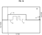
- Trace 126 represents an idealized (noiseless) return signal that is scattered from an object that is not moving (and thus the return is not Doppler shifted). The amplitude is reduced, but the code 00011010 is recognizable.
- Trace 127 represents an idealized (noiseless) return signal that is scattered from an object that is moving and is therefore Doppler shifted. The return is not at the proper optical frequency f c+f 0 and is not well detected in the expected frequency band, so the amplitude is diminished.
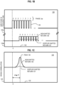
- FIG. 1C is a schematic graph 130 that illustrates example cross-correlations of the transmitted signal with two returned signals, according to an embodiment.
- phase coded ranging the arrival of the phase coded reflection is detected in the return by cross correlating the transmitted signal or other reference signal with the returned signal, implemented practically by cross correlating the code for a RF signal with a electrical signal from an optical detector using heterodyne detection and thus down-mixing back to the RF band.
- the horizontal axis 132 indicates a lag time in arbitrary units applied to the coded signal before performing the cross correlation calculation with the returned signal.
- the vertical axis 134 indicates amplitude of the cross correlation computation.
- Trace 136 represents cross correlation with an idealized (noiseless) return signal that is reflected from an object that is not moving (and thus the return is not Doppler shifted).
- a peak occurs at a time ⁇ t after the start of the transmitted signal. This indicates that the returned signal includes a version of the transmitted phase code beginning at the time ⁇ t.
- the range R to the reflecting (or backscattering) object is computed from the two way travel time delay based on the speed of light c in the medium, as given by Equation 3.
- R c ⁇ ⁇ t / 2
- the vertical axis 144b indicates spectral density in arbitrary units relative to zero, and is offset from axis 144a to separate traces.
- Trace 145 represents a transmitted signal; and, a peak occurs at the proper RF f 0 .
- Trace 146 represents an idealized (noiseless) return signal that is backscatter from an object that is moving and is therefore Doppler shifted. The return does not have a peak at the proper RF f 0 ; but, instead, is blue shifted by ⁇ f D to a shifted frequency f S .
- an optical coupler is any component that affects the propagation of light within spatial coordinates to direct light from one component to another component, such as a vacuum, air, glass, crystal, mirror, lens, optical circulator, beam splitter, phase plate, polarizer, optical fiber, optical mixer, among others, alone or in some combination.
- the time duration of these codes is then between about 500 ns and 8 microseconds. It is noted that the range window can be made to extend to several kilometers under these conditions and that the Doppler resolution can also be quite high (depending on the duration of the transmitted signal).
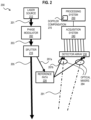
- the digital code module 372 in the processing system 350 sends an electrical signal that indicates a digital code of symbols to be imposed as phase changes on the optical carrier, represented as B( t ) where B(t) switches between 0 and ⁇ /2 as a function of t .
- the phase modulator 320 imposes the phase changes on the optical carrier by taking digital lines out of a field programmable gate array (FPGA), amplifying them, and driving the EO phase modulator.
- the transmitted optical signal, T is then given by Equation 6.
- T C exp i ⁇ t + B t where C is a constant that accounts for the reduction in I 0 by splitting of the fraction A and any amplification or further reduction imposed by the phase modulator 320.
- the phase-encoded optical signal output by the phase modulator 320 is transmitted through some optical couplers, such as the polarizing beam splitter (PBS) 322 or other circulator optics, after which it is scattered by any object 390 in the beam carrying the transmitted signal.
- PBS polarizing beam splitter
- the fiber coupled polarizing beam splitter combiners offer better isolation between the ports than the fiber based circulators as this optical component. This is important as signal that is not well isolated between transmit and receive will appear as an undesireable large peak in the range profiles. So the transmit signal is injected into port 1, is emitted out of port 2 and the back-scattered return signal is received in port 2 and exits port 3.
- step 413 the complex Fourier transform of the complex down mixed returned signal, S, is determined, for example using a complex FFT function FFT(S) implemented in hardware or software.
- the correct spectrum is computed using Equation 14a.
- S FFT circshift FFT S , ⁇ D where circshift (x,y) shifts a function x of an independent variable over a finite domain by an amount y in the independent variable such that anything shifted off one end of the finite domain is shifted on to the opposite end of the finite domain.
- the correct spectrum is computed using Equation 14b, which removes the Doppler effect by multiplication with a complex exponential and then calculating the FFT, as indicated in Equation 13.
- S FFT FFT S * exp ⁇ i ⁇ D t
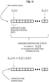
- step 423 the cross-correlation, XC, of the phase encoding, exp(iB(t)), with the corrected complex signal, Scorr, is determined, designated XC(Code, Scorr) for each of the M independent blocks of N symbols, and then averaged.
- this is done by taking the inverse Fast Fourier Transform (invFFT) of the corrected complex spectrum S FFT and correlating that corrected complex return Scorr with the digital signal exp(iB(t)) representing the code, as given by Equation 15a.
- invFFT inverse Fast Fourier Transform
- the FFT based convolution to determine the cross correlation can also be efficiently performed with a finite-impulse-response (FIR) filter based convolution as given by Equation 15c.
- FIR finite-impulse-response
- This has the potential to be more efficient for some shorter code lengths and in some computational hardware settings (FPGA).
- FPGA computational hardware settings
- k in the cross-correlation.
- the dot multiply (*) implies a series of inner products at different shifts (k) between the reference code B m and the corrected signal S .
- the FIR approach of FIG. 15c implies a simple register shift operation and simple multiply compared to the more complicated FFT method of FIG. 15b.
- the repeated shift and multiply of the FIR approach can be more computationally efficient for shorter codes, B.
- step 431 it is determined whether there is another spot to illuminate in a scene of interest, e.g., by scanning to view a new spot in the scene of interest. If so, control passes back to step 405 and following steps to illuminate the next spot and process any returns. In some embodiments using multi-spot averaging, the new spot is added to the average and the oldest spot is removed, or P new spots are collected in the loop formed by steps 405 through 409. If there is not another spot to illuminate, then the results are used, and control passes to step 433.
- this involves moving a vehicle to avoid a collision with an object, wherein a closing speed between the vehicle and the object is determined based on a size of the Doppler effect at a plurality of spots illuminated by the transmitted optical signal. In some embodiments, this involves identifying the vehicle or identifying the object on the collision course based on a point cloud of Doppler corrected positions at a plurality of spots illuminated by the transmitted optical signal. Filtering the point cloud data based on Doppler has the effect of identifying and removing vegetation that may be moving in the breeze. Hard objects, man-made objects, or dense objects are then better revealed by the filtering process. This can be advantageous in defense and surveillance scenarios. In the vehicle scenario - the Doppler can be used to segment objects (i.e. road surface versus moving vehicle).
- step 433 includes associating each delay time with one of the Doppler shifts, assuming that a particular return is based on an object or part of an object moving at a particular average speed over the duration of one transmitted signal.
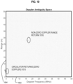
- Doppler correction only those range peaks associated with that Doppler correction will be present in the cross correlation. So it is improbable to incorrectly pair a given range and Doppler in the case of multiple instances. Put another way, the ambiguity function of this approach guarantees that there can be no confusion. This is demonstrated in the example embodiment below with reference to FIG. 10 showing "Doppler Ambiguity Space". This image was created by mapping out the range-Doppler space by computing the ranging cross-correlation at a wide set of possible Doppler corrections. The spots indicate the returns and the space is indeed very sparse.
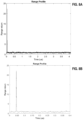
- FIG. 5A is a graph that illustrates example electrical in-phase (I) and quadrature (Q) output by optical detectors for an essentially stationary object that does not introduce a significant Doppler shift, according to an embodiment.
- the vertical axis indicates electrical signal in volts.
- the drawing labels I as Ch1, and Q as Ch2, and ⁇ s as us. Data is plotted for a single block of 2048 pulses.
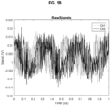
- FIG. 5B is a graph that illustrates example electrical amplitude and quadrature output by optical detectors for a moving object that does introduce a significant Doppler shift, according to an embodiment.
- the horizontal axis indicates time of arrival from a start time at zero in ⁇ s.
- the vertical axis indicates electrical signal in volts.
- the drawing labels I as Ch1, and Q as Ch2, and ⁇ s as us.
- the Doppler component of the return is evident as a sinusoidal pattern with a period of about 0.3 ⁇ s in both the in-phase, Ch1, and quadrature, Ch2, signals, corresponding to a Doppler shift of about 3 MHz
- This example used 1.55 micron wavelength (193.414489 THz), so this indicates a speed of about 4.7 m/s. This Doppler effect interferes with the correlation of the raw signal with the encoded phase exp(iB(t)).
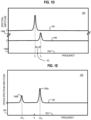
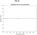
- FIG. 6A is a graph that illustrates an example cross spectrum for the in-phase and quadrature components of the returned signals for an essentially stationary object that does not introduce a significant Doppler shift, according to an embodiment.
- the horizontal axis indicates frequency in megahertz over a span from 0 to 450 MHz.
- the vertical axis indicates amplitude of the imaginary component of the cross spectrum in arbitrary units and extends from -20 to +20. As indicated by Equation 12, for example, this amplitude is expected to reveal peaks at Doppler shift frequencies; and, so the drawing vertical axis is labeled Doppler return.
- a trace in FIG. 6A shows no evident peak; thus, any target is not moving with respect to the LIDAR system and no Doppler compensation is needed or applied.
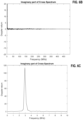
- FIG. 6B and FIG. 6C are graphs that illustrate an example cross spectrum for the in-phase and quadrature components of the returned signals for a moving object that does introduce a significant Doppler shift, according to an embodiment.
- the horizontal axis indicates frequency in megahertz and spans the same extent as in FIG. 6A .
- the vertical axis indicates amplitude of the imaginary component of the cross spectrum (indicative of Doppler return) in arbitrary units, and also spans the same extent as in FIG. 6A .
- a trace in FIG. 6B shows significant amplitude at low frequencies, below about 10 MHz; thus, some object is moving with respect to the LIDAR system and some Doppler compensation is applied in various embodiments.
- FIG. 6B shows significant amplitude at low frequencies, below about 10 MHz; thus, some object is moving with respect to the LIDAR system and some Doppler compensation is applied in various embodiments.
- the horizontal axis indicates frequency in megahertz and spans 1/45th of the range spanned in FIG. 6A , extending only to 10 MHz.
- the vertical axis indicates amplitude of the imaginary component of the cross spectrum (indicative of Doppler return) in arbitrary units; and, extends from 0 to 120, 3 times the extent of the vertical axes in FIG. 6A and FIG. 6B and 6 times the positive portion of the vertical axis in the previous plots.
- the trace shows a clear peak at 3 MHz with a value over 110 arbitrary units.
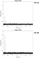
- FIG. 7A and FIG. 7B are graphs that illustrate an example trace of cross-correlation amplitude versus time (range profile) in the returned signal for an essentially stationary object without averaging over several blocks of the transmitted signal, according to an embodiment.
- the horizontal axis indicates travel time in microseconds ( ⁇ s, labelled us) and spans travel times from 0 to 2 microseconds.
- the vertical axis indicates amplitude of the cross-correlation (indicative of a backscattered return signal) in arbitrary units.
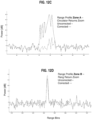
- FIG. 8A and FIG. 8B are graphs that illustrate an example trace of cross-correlation amplitude versus time (range profile) in the returned signal for a moving object with Doppler compensation, according to an embodiment.
- the horizontal axis indicates travel time in microseconds (us) and spans travel times from 0 to 4 microseconds (labeled us), twice the span of the horizontal axis in FIG. 7A and FIG. 7C .
- the vertical axis indicates amplitude of the cross-correlation (indicative of a backscattered return signal) in arbitrary units, spanning values from 0 to 25, more than three times the span of the vertical axis in FIG. 7A through FIG. 7D .
- a trace in FIG. 8A shows significant amplitude at one travel time, near 0.1.
- FIG. 8B the short travel time portion of the trace is expanded.
- the horizontal axis indicates time in microseconds (us) and spans 1/10th of the range as FIG. 8A , extending only to 0.4 ⁇ s (us).
- the vertical axis is the same as the vertical axis in FIG. 8A .
- a peak indicating two-way travel time is clearly evident in the trace of FIG.
- FIG. 9B is graph that illustrate an example superior trace of cross-correlation amplitude versus time (range profile) in the returned signal for a moving object, with Doppler compensation based on a mixed optical signal that is separated into in-phase optical signal and a quadrature optical signal, according to an embodiment.
- the horizontal axis indicates time in microseconds ( ⁇ s, signified by the abbreviation us); and, the vertical axis indicates cross correlation indicative of a return signal detected.
- the target was the same actively rotating fan blade as used for the data in FIG. 9A .
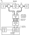
- the configuration uses separated in-phase (I) and quadrature (Q) components depicted as optical signals 364 in FIG. 3B ..
- FIG. 10 is a graph that illustrates an example Doppler Ambiguity space, to show easily distinguished Doppler effects, according to an embodiment.
- This image was created by mapping out the range-Doppler space by computing the ranging cross-correlation at a wide set of possible Doppler corrections.
- the horizontal axis indicates Doppler Frequency in MHz; and the vertical axis indicates range in meters.
- Intensity of the cross correlation is indicated by darkness of pixels. The only dark pixels are in area 1015 indicating circulator output that did not leave the device and therefore has no Doppler and in area 1016 indicating a Doppler of about 17 MHz at a range of about 27 meters.
- the space is indeed very sparse.
- FIG. 12A through FIG. 12D are graphs that illustrate example range signals before and after corrections to remove returns from internal optics, according to an embodiment.
- the trace shows the correlation peaks before subtracting the average of 32 spots. A large peak appears about 100 m and a smaller peak at about 2000m.
- the axes are the same, but the trace shows the correlation peaks after correction by subtracting the average of 32 spots.
- FIG. 13 is an image that illustrates example multiple range returns with multiple different Doppler shifts successfully processed, according to an embodiment.
- This image was collected between +/- 25 deg in the horizontal (a 50 degree horizontal field of view) and over a 10 deg vertical field of view.
- the scene was scanned at a 10Hz frame rate with a vertical zipper pattern.
- a 2048 code was utilized. It was played out at a 625Mbps rate and the signal was sampled at 1.25 Gsps.
- the data was processed and stored in real time using a CUDA implementation of the algorithms described.
- the scene was a parking lot with several people walking around.
- the 10 degree vertical angle captured the walker's legs and feet.
- the coloration shows Doppler value such that the composite of several frames shown shows the tracks of people walking at different rates towards and away from the sensor.
- the desired type of target identification, spatial resolution and accuracy, and object speed resolution and accuracy are used to select values for one or more parameters of the systems described above.
- parameters include one or more of code length, code block length, number of code blocks for averaging, the code itself (looking into engineered codes), shift between signal and code for better detection at long range, optimizations for speed, data acquisition rate, depth of phase modulation, transmitted laser power, laser spot size, scanning method and scan pattern.
- a sequence of one or more digits constitutes digital data that is used to represent a number or code for a character.
- information called analog data is represented by a near continuum of measurable values within a particular range.
- Computer system 1400, or a portion thereof, constitutes a means for performing one or more steps of one or more methods described herein.
- a sequence of binary digits constitutes digital data that is used to represent a number or code for a character.
- a bus 1410 includes many parallel conductors of information so that information is transferred quickly among devices coupled to the bus 1410.
- One or more processors 1402 for processing information are coupled with the bus 1410.
- a processor 1402 performs a set of operations on information.
- the set of operations include bringing information in from the bus 1410 and placing information on the bus 1410.
- the set of operations also typically include comparing two or more units of information, shifting positions of units of information, and combining two or more units of information, such as by addition or multiplication.
- a sequence of operations to be executed by the processor 1402 constitutes computer instructions.
- Computer system 1400 also includes a memory 1404 coupled to bus 1410.
- the memory 1404 such as a random access memory (RAM) or other dynamic storage device, stores information including computer instructions. Dynamic memory allows information stored therein to be changed by the computer system 1400. RAM allows a unit of information stored at a location called a memory address to be stored and retrieved independently of information at neighboring addresses.
- the memory 1404 is also used by the processor 1402 to store temporary values during execution of computer instructions.
- the computer system 1400 also includes a read only memory (ROM) 1406 or other static storage device coupled to the bus 1410 for storing static information, including instructions, that is not changed by the computer system 1400.
- ROM read only memory
- Also coupled to bus 1410 is a non-volatile (persistent) storage device 1408, such as a magnetic disk or optical disk, for storing information, including instructions, that persists even when the computer system 1400 is turned off or otherwise loses power.
- Information is provided to the bus 1410 for use by the processor from an external input device 1412, such as a keyboard containing alphanumeric keys operated by a human user, or a sensor.
- an external input device 1412 such as a keyboard containing alphanumeric keys operated by a human user, or a sensor.
- a sensor detects conditions in its vicinity and transforms those detections into signals compatible with the signals used to represent information in computer system 1400.
- bus 1410 Other external devices coupled to bus 1410, used primarily for interacting with humans, include a display device 1414, such as a cathode ray tube (CRT) or a liquid crystal display (LCD), for presenting images, and a pointing device 1416, such as a mouse or a trackball or cursor direction keys, for controlling a position of a small cursor image presented on the display 1414 and issuing commands associated with graphical elements presented on the display 1414.
- a display device 1414 such as a cathode ray tube (CRT) or a liquid crystal display (LCD)
- LCD liquid crystal display
- pointing device 1416 such as a mouse or a trackball or cursor direction keys
- special purpose hardware such as an application specific integrated circuit (IC) 1420
- IC application specific integrated circuit
- the special purpose hardware is configured to perform operations not performed by processor 1402 quickly enough for special purposes.
- application specific ICs include graphics accelerator cards for generating images for display 1414, cryptographic boards for encrypting and decrypting messages sent over a network, speech recognition, and interfaces to special external devices, such as robotic arms and medical scanning equipment that repeatedly perform some complex sequence of operations that are more efficiently implemented in hardware.
- Computer system 1400 also includes one or more instances of a communications interface 1470 coupled to bus 1410.
- Communication interface 1470 provides a two-way communication coupling to a variety of external devices that operate with their own processors, such as printers, scanners and external disks. In general the coupling is with a network link 1478 that is connected to a local network 1480 to which a variety of external devices with their own processors are connected.
- communication interface 1470 may be a parallel port or a serial port or a universal serial bus (USB) port on a personal computer.
- communications interface 1470 is an integrated services digital network (ISDN) card or a digital subscriber line (DSL) card or a telephone modem that provides an information communication connection to a corresponding type of telephone line.
- ISDN integrated services digital network
- DSL digital subscriber line
- a communication interface 1470 is a cable modem that converts signals on bus 1410 into signals for a communication connection over a coaxial cable or into optical signals for a communication connection over a fiber optic cable.
- communications interface 1470 may be a local area network (LAN) card to provide a data communication connection to a compatible LAN, such as Ethernet.
- LAN local area network
- Wireless links may also be implemented.
- Carrier waves, such as acoustic waves and electromagnetic waves, including radio, optical and infrared waves travel through space without wires or cables. Signals include man-made variations in amplitude, frequency, phase, polarization or other physical properties of carrier waves.
- the communications interface 1470 sends and receives electrical, acoustic or electromagnetic signals, including infrared and optical signals, that carry information streams, such as digital data.
- Non-volatile media include, for example, optical or magnetic disks, such as storage device 1408.
- Volatile media include, for example, dynamic memory 1404.
- Transmission media include, for example, coaxial cables, copper wire, fiber optic cables, and waves that travel through space without wires or cables, such as acoustic waves and electromagnetic waves, including radio, optical and infrared waves.
- the term computer-readable storage medium is used herein to refer to any medium that participates in providing information to processor 1402, except for transmission media.
- Computer-readable media include, for example, a floppy disk, a flexible disk, a hard disk, a magnetic tape, or any other magnetic medium, a compact disk ROM (CD-ROM), a digital video disk (DVD) or any other optical medium, punch cards, paper tape, or any other physical medium with patterns of holes, a RAM, a programmable ROM (PROM), an erasable PROM (EPROM), a FLASH-EPROM, or any other memory chip or cartridge, a carrier wave, or any other medium from which a computer can read.
- the term non-transitory computer-readable storage medium is used herein to refer to any medium that participates in providing information to processor 1402, except for carrier waves and other signals.
- Logic encoded in one or more tangible media includes one or both of processor instructions on a computer-readable storage media and special purpose hardware, such as ASIC 1420.
- Network link 1478 typically provides information communication through one or more networks to other devices that use or process the information.
- network link 1478 may provide a connection through local network 1480 to a host computer 1482 or to equipment 1484 operated by an Internet Service Provider (ISP).
- ISP equipment 1484 in turn provides data communication services through the public, world-wide packet-switching communication network of networks now commonly referred to as the Internet 1490.
- a computer called a server 1492 connected to the Internet provides a service in response to information received over the Internet.
- server 1492 provides information representing video data for presentation at display 1414.
- the invention is related to the use of computer system 1400 for implementing the techniques described herein. According to one embodiment of the invention, those techniques are performed by computer system 1400 in response to processor 1402 executing one or more sequences of one or more instructions contained in memory 1404. Such instructions, also called software and program code, may be read into memory 1404 from another computer-readable medium such as storage device 1408. Execution of the sequences of instructions contained in memory 1404 causes processor 1402 to perform the method steps described herein.
- hardware such as application specific integrated circuit 1420, may be used in place of or in combination with software to implement the invention. Thus, embodiments of the invention are not limited to any specific combination of hardware and software.
- Computer system 1400 can send and receive information, including program code, through the networks 1480, 1490 among others, through network link 1478 and communications interface 1470.
- a server 1492 transmits program code for a particular application, requested by a message sent from computer 1400, through Internet 1490, ISP equipment 1484, local network 1480 and communications interface 1470.
- the received code may be executed by processor 1402 as it is received, or may be stored in storage device 1408 or other non-volatile storage for later execution, or both. In this manner, computer system 1400 may obtain application program code in the form of a signal on a carrier wave.
- instructions and data may initially be carried on a magnetic disk of a remote computer such as host 1482.
- the remote computer loads the instructions and data into its dynamic memory and sends the instructions and data over a telephone line using a modem.
- a modem local to the computer system 1400 receives the instructions and data on a telephone line and uses an infra-red transmitter to convert the instructions and data to a signal on an infra-red a carrier wave serving as the network link 1478.
- An infrared detector serving as communications interface 1470 receives the instructions and data carried in the infrared signal and places information representing the instructions and data onto bus 1410.
- Bus 1410 carries the information to memory 1404 from which processor 1402 retrieves and executes the instructions using some of the data sent with the instructions.
- the instructions and data received in memory 1404 may optionally be stored on storage device 1408, either before or after execution by the processor 1402.
- FIG. 15 illustrates a chip set 1500 upon which an embodiment of the invention may be implemented.
- Chip set 1500 is programmed to perform one or more steps of a method described herein and includes, for instance, the processor and memory components described with respect to FIG. 14 incorporated in one or more physical packages (e.g., chips).
- a physical package includes an arrangement of one or more materials, components, and/or wires on a structural assembly (e.g., a baseboard) to provide one or more characteristics such as physical strength, conservation of size, and/or limitation of electrical interaction.
- the chip set can be implemented in a single chip.
- Chip set 1500, or a portion thereof constitutes a means for performing one or more steps of a method described herein.
- the chip set 1500 includes a communication mechanism such as a bus 1501 for passing information among the components of the chip set 1500.
- a processor 1503 has connectivity to the bus 1501 to execute instructions and process information stored in, for example, a memory 1505.
- the processor 1503 may include one or more processing cores with each core configured to perform independently.
- a multi-core processor enables multiprocessing within a single physical package. Examples of a multi-core processor include two, four, eight, or greater numbers of processing cores.
- the processor 1503 may include one or more microprocessors configured in tandem via the bus 1501 to enable independent execution of instructions, pipelining, and multithreading.
- the processor 1503 may also be accompanied with one or more specialized components to perform certain processing functions and tasks such as one or more digital signal processors (DSP) 1507, or one or more application-specific integrated circuits (ASIC) 1509.
- DSP digital signal processors
- ASIC application-specific integrated circuits
- a DSP 1507 typically is configured to process real-world signals (e.g., sound) in real time independently of the processor 1503.
- an ASIC 1509 can be configured to performed specialized functions not easily performed by a general purposed processor.
- Other specialized components to aid in performing the inventive functions described herein include one or more field programmable gate arrays (FPGA) (not shown), one or more controllers (not shown), or one or more other special-purpose computer chips.
- FPGA field programmable gate arrays
- the processor 1503 and accompanying components have connectivity to the memory 1505 via the bus 1501.
- the memory 1505 includes both dynamic memory (e.g., RAM, magnetic disk, writable optical disk, etc.) and static memory (e.g., ROM, CD-ROM, etc.) for storing executable instructions that when executed perform one or more steps of a method described herein.
- the memory 1505 also stores the data associated with or generated by the execution of one or more steps of the methods described herein.
- indefinite article “a” or “an” is meant to indicate one or more of the item, element or step modified by the article.
- a value is “about” another value if it is within a factor of two (twice or half) of the other value. While example ranges are given, unless otherwise clear from the context, any contained ranges are also intended in various embodiments. Thus, a range from 0 to 10 includes the range 1 to 4 in some embodiments.
Landscapes
- Physics & Mathematics (AREA)
- Engineering & Computer Science (AREA)
- Electromagnetism (AREA)
- Computer Networks & Wireless Communication (AREA)
- General Physics & Mathematics (AREA)
- Radar, Positioning & Navigation (AREA)
- Remote Sensing (AREA)
- Optical Radar Systems And Details Thereof (AREA)
Applications Claiming Priority (3)
| Application Number | Priority Date | Filing Date | Title |
|---|---|---|---|
| US15/423,978 US10422880B2 (en) | 2017-02-03 | 2017-02-03 | Method and system for doppler detection and doppler correction of optical phase-encoded range detection |
| PCT/US2018/016632 WO2018144853A1 (en) | 2017-02-03 | 2018-02-02 | Method and system for doppler detection and doppler correction of optical phase-encoded range detection |
| EP18748729.3A EP3577865B1 (de) | 2017-02-03 | 2018-02-02 | Verfahren und system zur doppler-detektion und doppler-korrektur der detektion eines optischen phasencodierten bereichs |
Related Parent Applications (1)
| Application Number | Title | Priority Date | Filing Date |
|---|---|---|---|
| EP18748729.3A Division EP3577865B1 (de) | 2017-02-03 | 2018-02-02 | Verfahren und system zur doppler-detektion und doppler-korrektur der detektion eines optischen phasencodierten bereichs |
Publications (2)
| Publication Number | Publication Date |
|---|---|
| EP4397993A2 true EP4397993A2 (de) | 2024-07-10 |
| EP4397993A3 EP4397993A3 (de) | 2024-10-16 |
Family
ID=63037154
Family Applications (2)
| Application Number | Title | Priority Date | Filing Date |
|---|---|---|---|
| EP24177690.5A Pending EP4397993A3 (de) | 2017-02-03 | 2018-02-02 | Verfahren und system zur doppler-detektion und doppler-korrektur der detektion eines optischen phasencodierten bereichs |
| EP18748729.3A Active EP3577865B1 (de) | 2017-02-03 | 2018-02-02 | Verfahren und system zur doppler-detektion und doppler-korrektur der detektion eines optischen phasencodierten bereichs |
Family Applications After (1)
| Application Number | Title | Priority Date | Filing Date |
|---|---|---|---|
| EP18748729.3A Active EP3577865B1 (de) | 2017-02-03 | 2018-02-02 | Verfahren und system zur doppler-detektion und doppler-korrektur der detektion eines optischen phasencodierten bereichs |
Country Status (6)
| Country | Link |
|---|---|
| US (3) | US10422880B2 (de) |
| EP (2) | EP4397993A3 (de) |
| JP (2) | JP6919972B2 (de) |
| KR (3) | KR102214061B1 (de) |
| CN (2) | CN110268683B (de) |
| WO (1) | WO2018144853A1 (de) |
Families Citing this family (97)
| Publication number | Priority date | Publication date | Assignee | Title |
|---|---|---|---|---|
| US10505643B2 (en) * | 2015-03-26 | 2019-12-10 | Lg Electronics Inc. | Method and device for estimating doppler frequency by using beam scanning process in wireless communication system |
| US10036812B2 (en) | 2015-06-24 | 2018-07-31 | Blackmore Sensors and Analytics Inc. | Method and system for three dimensional digital holographic aperture synthesis |
| KR102380216B1 (ko) | 2016-11-29 | 2022-03-28 | 블랙모어 센서스 앤드 애널리틱스, 엘엘씨 | 포인트 클라우드 데이터 세트에서 객체의 분류를 위한 방법 및 시스템 |
| WO2018102188A1 (en) | 2016-11-30 | 2018-06-07 | Blackmore Sensors and Analytics Inc. | Method and system for automatic real-time adaptive scanning with optical ranging systems |
| EP3548926B1 (de) | 2016-11-30 | 2024-05-29 | Aurora Operations, Inc. | Verfahren und system zur adaptiven abtastung mit optischen entfernungsmesssystemen |
| EP3548841B1 (de) | 2016-11-30 | 2025-11-12 | Aurora Operations, Inc. | Verfahren und system zur doppler-detektion und doppler-korrektur der entfernnungsbestimmung mit optischen chirps |
| US10422880B2 (en) | 2017-02-03 | 2019-09-24 | Blackmore Sensors and Analytics Inc. | Method and system for doppler detection and doppler correction of optical phase-encoded range detection |
| US10564268B2 (en) | 2017-02-17 | 2020-02-18 | Institut National D'optique | Phase-error correction in a synthetic aperture imaging system with local oscillator time delay adjustment |
| US10388006B2 (en) * | 2017-05-31 | 2019-08-20 | Institut National D'optique | Synthetic aperture imaging assisted by three-dimensional scanning imaging for height reconstruction |
| US11428790B2 (en) * | 2017-06-05 | 2022-08-30 | Texas Instruments Incorporated | Narrowband TIA and signaling for optical distance measurement systems |
| US10401495B2 (en) | 2017-07-10 | 2019-09-03 | Blackmore Sensors and Analytics Inc. | Method and system for time separated quadrature detection of doppler effects in optical range measurements |
| US10534084B2 (en) | 2017-07-27 | 2020-01-14 | Blackmore Sensors & Analytics, Llc | Method and system for using square wave digital chirp signal for optical chirped range detection |
| US10698113B2 (en) | 2017-08-09 | 2020-06-30 | Institut National D'optique | Three-dimensional synthetic aperture imaging using spatial amplitude modulation |
| US11650296B2 (en) * | 2018-02-16 | 2023-05-16 | Xiaotian Steve Yao | Optical sensing based on wavelength division multiplexed (WDM) light at different wavelengths in light detection and ranging LiDAR systems |
| US12510637B2 (en) | 2018-02-16 | 2025-12-30 | Xiaotian Steve Yao | Scan-less 3D optical sensing devices and associated lidar based on stacking of integrated photonic chips, wavelength division demultiplexing and position-to-angle conversion of a lens |
| CA3126889A1 (en) * | 2018-02-28 | 2019-09-06 | Illusense, Inc. | Method and device for interferometric range measurements |
| KR102457967B1 (ko) | 2018-04-23 | 2022-10-24 | 블랙모어 센서스 앤드 애널리틱스, 엘엘씨 | 코히어런트 거리 도플러 광학 센서를 이용한 자율 주행 차량 제어 방법 및 시스템 |
| DE112018007552B4 (de) * | 2018-06-12 | 2022-03-10 | Mitsubishi Electric Corporation | Optische-Distanz-Messungseinrichtung und Bearbeitungseinrichtung |
| US11536805B2 (en) | 2018-06-25 | 2022-12-27 | Silc Technologies, Inc. | Optical switching for tuning direction of LIDAR output signals |
| WO2020028146A1 (en) | 2018-07-30 | 2020-02-06 | Blackmore Sensors And Analytics, Llc | Method and system for optimizing scanning of coherent lidar in autonomous vehicles |
| CA3226819A1 (en) | 2018-08-10 | 2020-02-13 | Aurora Operations, Inc. | Method and system for scanning of coherent lidar with fan of collimated beams |
| US12535586B2 (en) | 2018-08-31 | 2026-01-27 | SiLC Technology, Inc. | Reduction of ADC sampling rates in LIDAR systems |
| KR102363751B1 (ko) | 2018-09-05 | 2022-02-15 | 블랙모어 센서스 앤드 애널리틱스, 엘엘씨 | 코히런트 lidar의 피치-캐치 스캐닝을 위한 방법 및 시스템 |
| JP7148063B2 (ja) | 2018-09-21 | 2022-10-05 | 国立研究開発法人情報通信研究機構 | Tofカメラ |
| JP7111170B2 (ja) * | 2018-10-17 | 2022-08-02 | 日本電気株式会社 | 測距装置及び測距方法 |
| CN112997094B (zh) * | 2018-11-13 | 2024-07-16 | 欧若拉运营公司 | 相位编码lidar中用于内反射减除的激光相位跟踪的方法和系统 |
| US11822010B2 (en) | 2019-01-04 | 2023-11-21 | Blackmore Sensors & Analytics, Llc | LIDAR system |
| CA3125553C (en) | 2019-01-04 | 2024-02-20 | Blackmore Sensors & Analytics, Llc | Lidar apparatus with rotatable polygon deflector having refractive facets |
| JP7192959B2 (ja) * | 2019-02-26 | 2022-12-20 | 日本電気株式会社 | 測距装置及び測距方法 |
| US10914825B2 (en) * | 2019-03-15 | 2021-02-09 | Raytheon Company | Technique for reducing impact of backscatter in coherent laser detection and ranging (LADAR) systems |
| CN113661411B (zh) | 2019-03-29 | 2025-03-14 | 欧若拉运营公司 | 用于调频连续波光检测和测距的可切换相干像素阵列 |
| CN110135299B (zh) * | 2019-04-30 | 2021-07-16 | 中国地质大学(武汉) | 一种用于浅水测深的单波段蓝绿激光波形分析方法及系统 |
| US12429569B2 (en) | 2019-05-17 | 2025-09-30 | Silc Technologies, Inc. | Identification of materials illuminated by LIDAR systems |
| US11448732B2 (en) | 2019-05-21 | 2022-09-20 | Northrop Grumman Systems Corporation | Frequency modulated scanning LIDAR with 360 degrees field of view |
| US11555891B2 (en) | 2019-05-21 | 2023-01-17 | Northrop Grumman Systems Corporation | Methods for large angle field of view scanning LIDAR with no movable parts |
| US11531111B2 (en) | 2019-05-21 | 2022-12-20 | Northrop Grumman Systems Corporation | 360 degrees field of view scanning lidar with no movable parts |
| CN110166080B (zh) * | 2019-05-22 | 2020-04-14 | 北京理工大学 | 相干多载波捕获方法及装置 |
| EP3748395B1 (de) * | 2019-06-06 | 2023-01-04 | Infineon Technologies AG | Verfahren und vorrichtung zur kompensation von streulicht, das durch ein objekt in einer szene verursacht wird, die von einer flugzeitkamera erfasst wird |
| JP7291385B2 (ja) * | 2019-06-26 | 2023-06-15 | 国立研究開発法人産業技術総合研究所 | 光学的測定装置及び測定方法 |
| US11650317B2 (en) | 2019-06-28 | 2023-05-16 | Silc Technologies, Inc. | Use of frequency offsets in generation of LIDAR data |
| US11002837B2 (en) * | 2019-07-15 | 2021-05-11 | Blackmore Sensors & Analytics, LLC. | Method and system for sidelobe suppression in phase encoded doppler LIDAR |
| US10838061B1 (en) * | 2019-07-16 | 2020-11-17 | Blackmore Sensors & Analytics, LLC. | Method and system for enhanced velocity resolution and signal to noise ratio in optical phase-encoded range detection |
| WO2021011472A1 (en) * | 2019-07-16 | 2021-01-21 | Blackmore Sensors & Analytics, Llc | Method and system for enhanced velocity resolution and signal to noise ratio in optical phase-encoded range detection |
| US10802120B1 (en) * | 2019-08-20 | 2020-10-13 | Luminar Technologies, Inc. | Coherent pulsed lidar system |
| EP4024085A4 (de) * | 2019-09-19 | 2022-11-09 | Beijing Guangshao Technology Co., Ltd | Verfahren und vorrichtung zur phasencodierenden ungesättigten modulation, verfahren zur entfernungsmessung und geschwindigkeitsmessung eines laserradars und laserradarsystem |
| US11754669B2 (en) * | 2019-09-30 | 2023-09-12 | Qualcomm Incorporated | Radar coordination for multi-radar coexistence |
| CN110596662B (zh) * | 2019-10-21 | 2023-03-21 | 立晟智能科技(成都)有限公司 | 一种mimo雷达的距离偏差校正方法 |
| CN111060920B (zh) * | 2019-12-18 | 2023-03-24 | 重庆大学 | 一种消除调频连续波激光测距系统多普勒误差的方法 |
| EP4081829A4 (de) * | 2019-12-23 | 2024-01-03 | Vai Photonics Pty Ltd | Lidar-vorrichtung und -verfahren |
| DE102020104385A1 (de) * | 2020-02-19 | 2021-08-19 | OSRAM Opto Semiconductors Gesellschaft mit beschränkter Haftung | Lasersystem und betriebsverfahren für ein lasersystem |
| KR102443656B1 (ko) * | 2020-03-30 | 2022-09-16 | 한국과학기술원 | 준-주파수 변조를 이용하여 거리를 측정하는 실리콘 위상배열 기반 라이다 장치 |
| ES2868473B2 (es) * | 2020-04-21 | 2022-02-28 | Mouro Labs S L | Sistema LIDAR con cambio de frecuencia Doppler suprimido |
| US11561291B2 (en) | 2020-04-30 | 2023-01-24 | Raytheon Company | High pulse repetition frequency lidar |
| CN113688642B (zh) * | 2020-05-19 | 2024-03-22 | 中国电子科技集团公司第十一研究所 | 身份识别系统及方法 |
| US11428785B2 (en) | 2020-06-12 | 2022-08-30 | Ours Technology, Llc | Lidar pixel with active polarization control |
| US10960900B1 (en) | 2020-06-30 | 2021-03-30 | Aurora Innovation, Inc. | Systems and methods for autonomous vehicle control using depolarization ratio of return signal |
| US11740338B2 (en) * | 2020-07-02 | 2023-08-29 | Aptiv Technologies Limited | Resolving return signals among pixels in frequency-modulated continuous-wave (FMCW) lidar systems |
| US12481034B2 (en) | 2020-08-10 | 2025-11-25 | Luminar Technologies, Inc. | Lidar system with input optical element |
| US20220043202A1 (en) | 2020-08-10 | 2022-02-10 | Luminar, Llc | Semiconductor optical amplifier with bragg grating |
| US10884130B1 (en) * | 2020-08-18 | 2021-01-05 | Aeva, Inc. | LIDAR system noise calibration and target detection |
| US11385339B2 (en) * | 2020-09-04 | 2022-07-12 | Ours Technology, Llc | LIDAR waveform generation system |
| US11693107B2 (en) * | 2020-09-29 | 2023-07-04 | Steradian Semiconductors Private Limited | System, device and method for efficient MIMO radar |
| EP4226183A1 (de) * | 2020-10-09 | 2023-08-16 | Aeva, Inc. | Verfahren zur kompensation von phasenstörungen in einem lidar-system |
| US12055664B2 (en) | 2020-10-09 | 2024-08-06 | Luminar Technologies, Inc. | Dual photodiode light detection and ranging |
| JP7582320B2 (ja) * | 2020-10-14 | 2024-11-13 | 日本電気株式会社 | 光測距装置及び光測距方法 |
| US11327158B1 (en) * | 2020-10-19 | 2022-05-10 | Aeva, Inc. | Techniques to compensate for mirror Doppler spreading in coherent LiDAR systems using matched filtering |
| US12429746B2 (en) | 2020-10-20 | 2025-09-30 | Xiaotian Steve Yao | Optical beam scanning based on waveguide switching and position-to-angle conversion of a lens and applications |
| US10948598B1 (en) | 2020-11-25 | 2021-03-16 | Aeva, Inc. | Coherent LiDAR system utilizing polarization-diverse architecture |
| DE102020215039A1 (de) | 2020-11-30 | 2022-06-02 | Robert Bosch Gesellschaft mit beschränkter Haftung | LiDAR-Sensorsystem |
| DE102020215040A1 (de) | 2020-11-30 | 2022-06-02 | Robert Bosch Gesellschaft mit beschränkter Haftung | LiDAR-Sensorsystem |
| DE102020215041A1 (de) | 2020-11-30 | 2022-06-02 | Robert Bosch Gesellschaft mit beschränkter Haftung | LiDAR-Sensor-System |
| US20220187468A1 (en) * | 2020-12-14 | 2022-06-16 | Waymo Llc | Coupled lasers for coherent distance and velocity measurements |
| US11782159B2 (en) * | 2020-12-30 | 2023-10-10 | Silc Technologies, Inc. | LIDAR system with encoded output signals |
| CN112965060B (zh) * | 2021-02-19 | 2024-11-15 | 加特兰微电子科技(上海)有限公司 | 生命特征参数的检测方法、装置和检测体征点的方法 |
| US12106528B2 (en) * | 2021-03-01 | 2024-10-01 | Waymo Llc | Generating scene flow labels for point clouds using object labels |
| DE102021111820A1 (de) | 2021-05-06 | 2022-11-10 | Robert Bosch Gesellschaft mit beschränkter Haftung | LiDAR-Sensor-System |
| CN113189607B (zh) * | 2021-05-18 | 2023-05-02 | 挚感(苏州)光子科技有限公司 | 一种激光调频连续波测距非线性调制解调系统 |
| US12541009B2 (en) | 2021-06-17 | 2026-02-03 | Silc Technologies, Inc. | Scanning multiple LIDAR system output signals |
| KR102527463B1 (ko) * | 2021-06-23 | 2023-05-03 | 람다이노비전 주식회사 | 의사 난수 2진 시퀀스를 이용한 라이다 |
| WO2023272359A1 (en) | 2021-06-30 | 2023-01-05 | Vai Photonics Pty Ltd | A lidar apparatus and process |
| JP7583685B2 (ja) * | 2021-07-28 | 2024-11-14 | 株式会社デンソー | 測定システム、測定方法、及び測定プログラム |
| US12411213B2 (en) | 2021-10-11 | 2025-09-09 | Silc Technologies, Inc. | Separation of light signals in a LIDAR system |
| EP4414747A4 (de) * | 2021-10-22 | 2024-10-30 | Huawei Technologies Co., Ltd. | Detektionssystem und endgerätevorrichtung |
| KR102665538B1 (ko) * | 2021-12-01 | 2024-05-20 | 고등기술연구원연구조합 | 부유식 풍황 계측 장치, 이의 제어방법, 컴퓨터 판독 가능한 기록 매체, 컴퓨터 프로그램 및 이를 이용하는 모니터링 시스템 |
| WO2023108199A1 (en) * | 2021-12-17 | 2023-06-22 | Baraja Pty Ltd | Spatial estimation systems including homodyne optical receivers |
| WO2023144888A1 (ja) * | 2022-01-25 | 2023-08-03 | 日本電気株式会社 | 特定システム、特定方法及び記憶媒体 |
| US12130363B2 (en) | 2022-02-03 | 2024-10-29 | Aurora Operations, Inc. | LIDAR system |
| US12553995B2 (en) | 2022-02-14 | 2026-02-17 | Silc Technologies, Inc. | Data refinement in optical systems |
| US12578443B2 (en) | 2022-04-23 | 2026-03-17 | Silc Technologies, Inc. | Data refinement in optical imaging systems |
| CN114839757A (zh) * | 2022-04-25 | 2022-08-02 | 金华市蓝海光电技术有限公司 | 一种小型化单筒望远激光测距仪 |
| US12422618B2 (en) | 2022-10-13 | 2025-09-23 | Silc Technologies, Inc. | Buried taper with reflecting surface |
| CN115392325B (zh) * | 2022-10-26 | 2023-08-18 | 中国人民解放军国防科技大学 | 一种基于CycleGan的多特征降噪调制识别方法 |
| US20240255627A1 (en) * | 2023-01-31 | 2024-08-01 | Aeva, Inc. | Techniques for mitigating cross-channel interference in fmcw lidar systems |
| US12578439B2 (en) | 2023-04-11 | 2026-03-17 | Silc Technologies, Inc. | Increasing resolution in imaging systems |
| US12571914B2 (en) | 2023-10-05 | 2026-03-10 | Aurora Operations, Inc. | Systems and methods of LIDAR sensor systems having amplifier protection circuits |
| CN117148380B (zh) * | 2023-10-31 | 2024-02-06 | 西安电子科技大学 | 基于频率下降优化的振动相位补偿卫星isal成像方法 |
| CN119687800B (zh) * | 2024-12-12 | 2025-11-28 | 厦门大学 | 基于复指数变换的激光自混合干涉位移测量方法及装置 |
Citations (2)
| Publication number | Priority date | Publication date | Assignee | Title |
|---|---|---|---|---|
| US5781156A (en) | 1995-10-09 | 1998-07-14 | Snaptrack, Inc. | GPS receiver and method for processing GPS signals |
| US7742152B2 (en) | 2006-06-23 | 2010-06-22 | University Of Kansas | Coherent detection scheme for FM chirped laser radar |
Family Cites Families (257)
| Publication number | Priority date | Publication date | Assignee | Title |
|---|---|---|---|---|
| US4099249A (en) | 1977-02-22 | 1978-07-04 | The United States Of America As Represented By The Secretary Of The Navy | Doppler processing method and apparatus |
| US4620192A (en) * | 1983-09-29 | 1986-10-28 | Raytheon Company | Continuous wave radar with ranging capability |
| US4648276A (en) * | 1984-01-27 | 1987-03-10 | Klepper John R | Apparatus for measuring the characteristics of an ultrasonic wave medium |
| FR2568688B1 (fr) | 1984-08-03 | 1986-09-05 | Thomson Csf | Systeme emetteur-recepteur pour imagerie laser |
| JPS6371674A (ja) | 1986-09-16 | 1988-04-01 | Matsushita Electric Ind Co Ltd | レ−ザ−測距装置 |
| US4804893A (en) | 1987-05-11 | 1989-02-14 | Caterpillar Industrial Inc. | Electric braking control |
| EP0364134B1 (de) | 1988-10-03 | 1992-04-29 | LUCAS INDUSTRIES public limited company | Vorrichtung zur Erfassung der Geschwindigkeit und der Richtung eines Fahrzeuges |
| GB2227965B (en) | 1988-10-12 | 1993-02-10 | Rolls Royce Plc | Apparatus for drilling a shaped hole in a workpiece |
| US5223986A (en) | 1990-08-09 | 1993-06-29 | Kaman Aerospace Corporation | Radiation projecting device |
| US5231401A (en) | 1990-08-10 | 1993-07-27 | Kaman Aerospace Corporation | Imaging lidar system |
| JP2765767B2 (ja) | 1991-05-20 | 1998-06-18 | 富士通テン株式会社 | Fm−cwレーダ装置 |
| US5227910A (en) | 1992-03-27 | 1993-07-13 | Khattak Anwar S | High resolution laser beam scanner and method for operation thereof |
| US5216534A (en) | 1992-04-24 | 1993-06-01 | E-Systems, Inc. | Read-write head for an optical tape recorder |
| JPH06148556A (ja) | 1992-11-10 | 1994-05-27 | Canon Inc | 光走査装置 |
| JPH06175062A (ja) | 1992-12-08 | 1994-06-24 | Matsushita Electric Ind Co Ltd | ポリゴン・ミラー |
| US7418346B2 (en) | 1997-10-22 | 2008-08-26 | Intelligent Technologies International, Inc. | Collision avoidance methods and systems |
| US7610146B2 (en) | 1997-10-22 | 2009-10-27 | Intelligent Technologies International, Inc. | Vehicle position determining system and method |
| JP3060912B2 (ja) | 1995-09-11 | 2000-07-10 | 富士通株式会社 | 回転多面鏡およびその製造方法 |
| JP2954871B2 (ja) | 1996-03-25 | 1999-09-27 | 株式会社先進材料利用ガスジェネレータ研究所 | 光ファイバセンサ |
| JPH09325290A (ja) | 1996-06-04 | 1997-12-16 | Matsushita Electric Ind Co Ltd | 走査光学装置 |
| DE19637616A1 (de) | 1996-09-16 | 1998-03-19 | Bosch Gmbh Robert | Verfahren zum automatischen Kalibrieren eines Wegsensors und Vorrichtung |
| US5828585A (en) | 1997-01-17 | 1998-10-27 | Delco Electronics Corporation | Vehicle speed signal calibration |
| US5999302A (en) | 1997-06-27 | 1999-12-07 | Speedring Systems, Inc. | Polygon scanner having a fluid film bearing and active correction of cross-scan and in-scan errors |
| JP4126114B2 (ja) | 1997-07-07 | 2008-07-30 | 茂雄 大槻 | 流体の観測面内ドプラ速度分布から面内流を推定する方法 |
| JPH11153664A (ja) | 1997-09-30 | 1999-06-08 | Sumitomo Electric Ind Ltd | 繰り返しパルス光を利用した物体検知装置 |
| JP3309067B2 (ja) | 1997-09-30 | 2002-07-29 | 福田 孝太郎 | 面内流れの表示方法 |
| US20020140924A1 (en) | 1999-01-08 | 2002-10-03 | Richard J. Wangler | Vehicle classification and axle counting sensor system and method |
| JP3422720B2 (ja) | 1999-04-13 | 2003-06-30 | 富士通株式会社 | レーザモジュールおよびこれを備えた光走査装置 |
| GB9909323D0 (en) | 1999-04-22 | 1999-06-16 | Thomas Swan & Company Limited | Phase modulator |
| JP2000338244A (ja) * | 1999-05-28 | 2000-12-08 | Mitsubishi Electric Corp | コヒーレントレーザレーダ装置 |
| US6433907B1 (en) | 1999-08-05 | 2002-08-13 | Microvision, Inc. | Scanned display with plurality of scanning assemblies |
| US6753950B2 (en) | 2000-01-26 | 2004-06-22 | Instro Precision Limited | Optical distance measurement |
| US6931055B1 (en) | 2000-04-18 | 2005-08-16 | Sirf Technology, Inc. | Signal detector employing a doppler phase correction system |
| US20020071109A1 (en) | 2000-07-24 | 2002-06-13 | Christopher Allen | Laser radar system and method |
| JP2002249058A (ja) | 2001-02-26 | 2002-09-03 | Koyo Seiko Co Ltd | 電動パワーステアリング装置 |
| DE10139237A1 (de) | 2001-08-09 | 2003-03-06 | Conti Temic Microelectronic | Vorrichtung zur Entfernungsmessung |
| DE10148069A1 (de) | 2001-09-28 | 2003-04-10 | Ibeo Automobile Sensor Gmbh | Verfahren zur Erkennung und Verfolgung von Objekten |
| JP3729127B2 (ja) | 2001-12-13 | 2005-12-21 | 株式会社村田製作所 | レーダ |
| US20040034304A1 (en) * | 2001-12-21 | 2004-02-19 | Chikayoshi Sumi | Displacement measurement method and apparatus, strain measurement method and apparatus elasticity and visco-elasticity constants measurement apparatus, and the elasticity and visco-elasticity constants measurement apparatus-based treatment apparatus |
| US6671595B2 (en) | 2002-01-08 | 2003-12-30 | Ford Global Technologies, Llc | Vehicle side slip angle estimation using dynamic blending and considering vehicle attitude information |
| US20040158155A1 (en) * | 2002-04-01 | 2004-08-12 | Njemanze Philip Chidi | Transcranial doppler spectroscopy for assessment of brain cognitive functions |
| AU2003239914A1 (en) | 2002-05-29 | 2003-12-19 | Kent L. Deines | System and method for measuring velocity using frequency modulation of laser output |
| US6871148B2 (en) | 2002-07-02 | 2005-03-22 | Battelle Memorial Institute | Ultrasonic system and technique for fluid characterization |
| US7324393B2 (en) | 2002-09-24 | 2008-01-29 | Sandisk Corporation | Method for compensated sensing in non-volatile memory |
| WO2005008271A2 (en) | 2002-11-26 | 2005-01-27 | Munro James F | An apparatus for high accuracy distance and velocity measurement and methods thereof |
| US20050083513A1 (en) * | 2002-12-20 | 2005-04-21 | Rogers Philip L. | Quadrature processed lidar system |
| AT413452B (de) | 2003-11-18 | 2006-03-15 | Riegl Laser Measurement Sys | Einrichtung zur aufnahme eines objektraumes |
| US7222007B2 (en) | 2004-01-07 | 2007-05-22 | Ford Global Technologies, Llc | Attitude sensing system for an automotive vehicle relative to the road |
| US7122691B2 (en) | 2004-03-30 | 2006-10-17 | Sumitomo Chemical Company, Limited | Process for producing compound, catalyst component for addition polymerization, process for producing catalyst for addition polymerization, and process for producing addition polymer |
| US7486802B2 (en) | 2004-06-07 | 2009-02-03 | Ford Global Technologies Llc | Adaptive template object classification system with a template generator |
| US7697748B2 (en) | 2004-07-06 | 2010-04-13 | Dimsdale Engineering, Llc | Method and apparatus for high resolution 3D imaging as a function of camera position, camera trajectory and range |
| JP2006148556A (ja) | 2004-11-19 | 2006-06-08 | Yaskawa Electric Corp | モニタデータ取得装置 |
| US7440084B2 (en) | 2004-12-16 | 2008-10-21 | Arete' Associates | Micromechanical and related lidar apparatus and method, and fast light-routing components |
| CA2597712C (en) | 2005-02-14 | 2013-08-13 | Digital Signal Corporation | Laser radar system and system and method for providing chirped electromagnetic radiation |
| US8488967B2 (en) | 2005-02-18 | 2013-07-16 | Telcordia Technologies, Inc. | System and method for OCDMA-based photonic layer security robustness to archival attack |
| JP4830311B2 (ja) | 2005-02-21 | 2011-12-07 | 株式会社デンソー | 車載用レーダ装置 |
| US7642952B2 (en) * | 2005-03-31 | 2010-01-05 | Panasonic Corporation | Spread spectrum radar apparatus |
| US20060239312A1 (en) | 2005-04-23 | 2006-10-26 | Telaris Inc. | Semiconductor Lasers in Optical Phase-Locked Loops |
| US7451033B2 (en) | 2005-06-10 | 2008-11-11 | Ford Global Technologies, Llc | Lateral and longitudinal velocity determination for an automotive vehicle |
| US7152490B1 (en) | 2005-08-15 | 2006-12-26 | Daniel Measurement And Control, Inc. | Methods for determining transducer delay time and transducer separation in ultrasonic flow meters |
| JP2007155467A (ja) | 2005-12-05 | 2007-06-21 | Nidec Sankyo Corp | 光ビーム走査装置 |
| US7544945B2 (en) | 2006-02-06 | 2009-06-09 | Avago Technologies General Ip (Singapore) Pte. Ltd. | Vertical cavity surface emitting laser (VCSEL) array laser scanner |
| JP4788365B2 (ja) | 2006-02-07 | 2011-10-05 | 株式会社富士通ゼネラル | リモコン信号受信回路 |
| US8174568B2 (en) | 2006-12-01 | 2012-05-08 | Sri International | Unified framework for precise vision-aided navigation |
| DE102007001103A1 (de) | 2007-01-04 | 2008-07-10 | Siemens Ag | Vertikale Ausrichtung eines Lidar-Sensors |
| CA2674830A1 (en) | 2007-01-05 | 2008-07-17 | Nestor, Inc. | Video speed detection system |
| US7917039B1 (en) | 2007-02-09 | 2011-03-29 | University Of Central Florida Research Foundation, Inc. | Signal processing using spectrally phase-encoded optical frequency combs |
| US7639347B2 (en) | 2007-02-14 | 2009-12-29 | Leica Geosystems Ag | High-speed laser ranging system including a fiber laser |
| US7573564B2 (en) | 2007-06-26 | 2009-08-11 | The United States Of America As Represented By The Secretary Of The Army | Systems for doppler tracking using photonic mixing detectors |
| US7835054B2 (en) | 2007-07-02 | 2010-11-16 | Texas Instruments Incorporated | Optical architecture having a rotating polygon for use in imaging systems |
| US7746450B2 (en) * | 2007-08-28 | 2010-06-29 | Science Applications International Corporation | Full-field light detection and ranging imaging system |
| EP2243042B1 (de) | 2008-01-16 | 2015-08-26 | Philips Intellectual Property & Standards GmbH | Lasersensorsystem auf grundlage von selbstmischender interferenz |
| WO2009107297A1 (ja) | 2008-02-25 | 2009-09-03 | 三菱電機株式会社 | 車載通信装置 |
| CN101236253B (zh) * | 2008-03-07 | 2010-07-07 | 中国科学院上海光学精密机械研究所 | 高精度测速测距激光雷达系统及测速测距方法 |
| JP4471018B2 (ja) | 2008-04-15 | 2010-06-02 | トヨタ自動車株式会社 | 無段変速機の制御装置 |
| US9041915B2 (en) | 2008-05-09 | 2015-05-26 | Ball Aerospace & Technologies Corp. | Systems and methods of scene and action capture using imaging system incorporating 3D LIDAR |
| JP5629052B2 (ja) * | 2008-06-03 | 2014-11-19 | 日立アロカメディカル株式会社 | 超音波診断装置 |
| WO2010006081A1 (en) | 2008-07-08 | 2010-01-14 | Chiaro Technologies, Inc. | Multiple channel locating |
| JP5752040B2 (ja) | 2008-09-11 | 2015-07-22 | ニコン・メトロロジー・エヌヴェ | 対チャープfmcwコヒーレントレーザレーダー用の小型の光ファイバ配置 |
| KR20100037487A (ko) | 2008-10-01 | 2010-04-09 | 엘지전자 주식회사 | 차량 네비게이션 방법 및 그 장치 |
| US8437901B2 (en) | 2008-10-15 | 2013-05-07 | Deere & Company | High integrity coordination for multiple off-road vehicles |
| EP2425506A2 (de) | 2009-04-29 | 2012-03-07 | Montana State University | Präziser breitband-frequenzmodulierter laser |
| US8882675B2 (en) * | 2009-07-16 | 2014-11-11 | Hitachi Aloka Medical, Ltd. | Methods and apparatus for ultrasound imaging |
| JP2011039490A (ja) | 2009-07-17 | 2011-02-24 | Sony Corp | 画像表示装置、頭部装着型ディスプレイ及び光ビーム伸長装置 |
| US8441622B2 (en) | 2009-07-28 | 2013-05-14 | Applied Concepts, Inc. | Lidar measurement device for vehicular traffic surveillance and method for use of same |
| US8125622B2 (en) | 2009-07-28 | 2012-02-28 | Applied Concepts, Inc. | Lidar measurement device with target tracking and method for use of same |
| JP2009288255A (ja) | 2009-09-11 | 2009-12-10 | Denso Corp | 推定装置 |
| JP2011134373A (ja) * | 2009-12-22 | 2011-07-07 | Toshiba Corp | 起動制御装置及び起動制御方法 |
| WO2011102130A1 (ja) * | 2010-02-18 | 2011-08-25 | パナソニック株式会社 | 超音波測定方法および超音波測定装置 |
| JP5402772B2 (ja) | 2010-03-25 | 2014-01-29 | 株式会社日本自動車部品総合研究所 | 光レーダ装置 |
| US9257048B1 (en) | 2010-04-21 | 2016-02-09 | The Boeing Company | Aircraft emergency landing route system |
| US20110292371A1 (en) | 2010-05-28 | 2011-12-01 | Optical Air Data Systems, Llc | Method and Apparatus for a Pulsed Coherent Laser Range Finder |
| US9229106B2 (en) | 2010-08-13 | 2016-01-05 | Ryan Dotson | Enhancement of range measurement resolution using imagery |
| JP5648368B2 (ja) | 2010-08-23 | 2015-01-07 | ミツミ電機株式会社 | 光走査装置 |
| US8509982B2 (en) | 2010-10-05 | 2013-08-13 | Google Inc. | Zone driving |
| US8692980B2 (en) | 2010-11-01 | 2014-04-08 | Advanced Scientific Concepts, Inc. | Flash LADAR collision avoidance system |
| JP5709476B2 (ja) | 2010-11-10 | 2015-04-30 | 富士通テン株式会社 | レーダ装置 |
| KR101760344B1 (ko) | 2010-11-24 | 2017-07-21 | 에스프린팅솔루션 주식회사 | 다면경 조립체, 이를 채용한 광주사장치 및 화상형성장치 |
| JP2011044750A (ja) | 2010-11-30 | 2011-03-03 | Sanyo Electric Co Ltd | 太陽電池モジュール |
| JP5686342B2 (ja) | 2011-01-28 | 2015-03-18 | 国立大学法人東北大学 | レーザレーダ装置およびレーザ合成開口レーダ装置 |
| US9323250B2 (en) | 2011-01-28 | 2016-04-26 | Intouch Technologies, Inc. | Time-dependent navigation of telepresence robots |
| CN102812380B (zh) | 2011-03-09 | 2016-01-20 | 株式会社东芝 | 医用图像处理装置 |
| US20120274922A1 (en) | 2011-03-28 | 2012-11-01 | Bruce Hodge | Lidar methods and apparatus |
| US8605998B2 (en) | 2011-05-06 | 2013-12-10 | Toyota Motor Engineering & Manufacturing North America, Inc. | Real-time 3D point cloud obstacle discriminator apparatus and associated methodology for training a classifier via bootstrapping |
| US9504100B2 (en) | 2011-05-31 | 2016-11-22 | Munro Design & Technologies, Llc | Selective radiation utilization apparatuses for high-efficiency photobioreactor illumination and methods thereof |
| BR112013031745B1 (pt) | 2011-06-10 | 2021-08-31 | Hewlett-Packard Development Company, L.P. | Aparelho de digitalização ótica, sistema de digitalização de disposição por laser e método de digitalização ótica |
| US9046909B2 (en) | 2011-09-02 | 2015-06-02 | Rambus Inc. | On-chip regulator with variable load compensation |
| US20130104661A1 (en) | 2011-10-31 | 2013-05-02 | Raytheon Company | Method and apparatus for range resolved laser doppler vibrometry |
| TWI435993B (zh) | 2011-11-16 | 2014-05-01 | Univ Nat Central | Special lamps with light changes |
| DE102012200139A1 (de) | 2012-01-05 | 2013-07-11 | Robert Bosch Gmbh | Verfahren und Vorrichtung zur radunabhängigen Geschwindigkeitsmessung bei einem Fahrzeug |
| US8942012B2 (en) | 2012-01-31 | 2015-01-27 | Semiconductor Components Industries, Llc | Method of forming a switched mode power supply controller device with an off mode and structure therefor |
| US9159135B2 (en) | 2012-03-28 | 2015-10-13 | Intel Corporation | Systems, methods, and computer program products for low-latency warping of a depth map |
| GB2501466A (en) | 2012-04-02 | 2013-10-30 | Univ Oxford | Localising transportable apparatus |
| US9248725B2 (en) | 2012-04-04 | 2016-02-02 | Ford Global Technologies, Llc | Panoramic roof module for a vehicle |
| US9300423B2 (en) | 2012-04-24 | 2016-03-29 | Zetta Research and Development LLC—ForC Series | Device for synchronizing a time base for V2V communictation |
| US9129532B2 (en) | 2012-04-24 | 2015-09-08 | Zetta Research and Development LLC, ForC series | Hybrid protocol transceiver for V2V communication |
| US9253753B2 (en) | 2012-04-24 | 2016-02-02 | Zetta Research And Development Llc-Forc Series | Vehicle-to-vehicle safety transceiver using time slots |
| US9696426B2 (en) | 2012-04-30 | 2017-07-04 | Michigan Aerospace Corporation | System and method for scan range gating |
| CN103608696B (zh) | 2012-05-22 | 2016-05-11 | 韩国生产技术研究院 | 3d扫描系统和获得3d图像的方法 |
| IN2015KN00237A (de) | 2012-06-27 | 2015-06-12 | Pentair Water Pool & Spa Inc | |
| US8831780B2 (en) | 2012-07-05 | 2014-09-09 | Stanislav Zelivinski | System and method for creating virtual presence |
| US9007569B2 (en) | 2012-08-03 | 2015-04-14 | The United States Of America As Represented By The Administrator Of The National Aeronautics And Space Administration | Coherent doppler lidar for measuring altitude, ground velocity, and air velocity of aircraft and spaceborne vehicles |
| US9134402B2 (en) | 2012-08-13 | 2015-09-15 | Digital Signal Corporation | System and method for calibrating video and lidar subsystems |
| US8948497B2 (en) | 2012-09-04 | 2015-02-03 | Digital Signal Corporation | System and method for increasing resolution of images obtained from a three-dimensional measurement system |
| US9383753B1 (en) | 2012-09-26 | 2016-07-05 | Google Inc. | Wide-view LIDAR with areas of special attention |
| US9196164B1 (en) | 2012-09-27 | 2015-11-24 | Google Inc. | Pedestrian notifications |
| US9488492B2 (en) | 2014-03-18 | 2016-11-08 | Sri International | Real-time system for multi-modal 3D geospatial mapping, object recognition, scene annotation and analytics |
| US9097800B1 (en) | 2012-10-11 | 2015-08-04 | Google Inc. | Solid object detection system using laser and radar sensor fusion |
| US8818609B1 (en) | 2012-11-15 | 2014-08-26 | Google Inc. | Using geometric features and history information to detect features such as car exhaust in point maps |
| JP2014115978A (ja) | 2012-11-19 | 2014-06-26 | Ricoh Co Ltd | 移動物体認識装置及びこれを用いた報知装置及びその移動物体認識装置に用いる移動物体認識用プログラム及び移動物体認識装置を備えた移動体 |
| US9618619B2 (en) | 2012-11-21 | 2017-04-11 | Nikon Corporation | Radar systems with dual fiber coupled lasers |
| WO2014083373A1 (en) * | 2012-11-28 | 2014-06-05 | B-K Medical Aps | Angle independent velocity spectrum determination |
| US9048824B2 (en) | 2012-12-12 | 2015-06-02 | Intel Corporation | Programmable equalization with compensated impedance |
| GB201303540D0 (en) | 2013-02-27 | 2013-04-10 | Arithmetica Ltd | Image processing |
| US9618742B1 (en) | 2013-03-08 | 2017-04-11 | Google Inc. | Rotatable mirror assemblies |
| US9086273B1 (en) | 2013-03-08 | 2015-07-21 | Google Inc. | Microrod compression of laser beam in combination with transmit lens |
| EP2806286B1 (de) | 2013-05-23 | 2019-07-10 | Veoneer Sweden AB | FMCW-Radar-Blockierungsdetektion |
| US9683928B2 (en) | 2013-06-23 | 2017-06-20 | Eric Swanson | Integrated optical system and components utilizing tunable optical sources and coherent detection and phased array for imaging, ranging, sensing, communications and other applications |
| US10013507B2 (en) | 2013-07-01 | 2018-07-03 | Here Global B.V. | Learning synthetic models for roof style classification using point clouds |
| US9683836B2 (en) | 2013-08-09 | 2017-06-20 | Conduent Business Services, Llc | Vehicle classification from laser scanners using fisher and profile signatures |
| AU2014306813A1 (en) | 2013-08-12 | 2016-03-31 | Flyby Media, Inc. | Visual-based inertial navigation |
| WO2016030656A1 (en) * | 2014-08-28 | 2016-03-03 | Aveillant Limited | Radar system and associated apparatus and methods |
| JP6304257B2 (ja) | 2013-09-12 | 2018-04-04 | パナソニック株式会社 | レーダ装置、車両及び移動体速度検出方法 |
| TWI510877B (zh) | 2013-10-23 | 2015-12-01 | Ind Tech Res Inst | 電壓補償電路及其控制方法 |
| US20150130607A1 (en) | 2013-11-11 | 2015-05-14 | David MacArthur | Rear Brake Light System |
| JP6146295B2 (ja) * | 2013-12-26 | 2017-06-14 | 株式会社豊田中央研究所 | レーダ装置および速度の方向測定方法 |
| KR102185727B1 (ko) | 2014-01-28 | 2020-12-02 | 삼성메디슨 주식회사 | 초음파 진단 장치 및 그 동작방법 |
| US10431099B2 (en) | 2014-02-21 | 2019-10-01 | FLIR Belgium BVBA | Collision avoidance systems and methods |
| US10422649B2 (en) | 2014-02-24 | 2019-09-24 | Ford Global Technologies, Llc | Autonomous driving sensing system and method |
| JP2015172491A (ja) | 2014-03-11 | 2015-10-01 | 富士通テン株式会社 | アンテナ、レーダ装置、および、車両制御システム |
| JP6222523B2 (ja) | 2014-03-11 | 2017-11-01 | 日本電気株式会社 | 移動目標抽出システム、移動目標抽出方法、情報処理装置およびその制御方法と制御プログラム |
| JP2015205176A (ja) | 2014-04-08 | 2015-11-19 | 株式会社トプコン | 眼科装置 |
| US9098754B1 (en) | 2014-04-25 | 2015-08-04 | Google Inc. | Methods and systems for object detection using laser point clouds |
| US9383442B2 (en) | 2014-05-12 | 2016-07-05 | Autoliv Asp, Inc. | Radar system and method for determining range, relative velocity and bearing of an object using continuous-wave and chirp signals |
| JP5844430B1 (ja) | 2014-06-27 | 2016-01-20 | 日立アロカメディカル株式会社 | 超音波診断装置 |
| US9575341B2 (en) | 2014-06-28 | 2017-02-21 | Intel Corporation | Solid state LIDAR circuit with waveguides tunable to separate phase offsets |
| US9523766B2 (en) | 2014-09-19 | 2016-12-20 | Institut National D'optique | Phase error correction in synthetic aperture imaging |
| AU2015333582B2 (en) | 2014-10-17 | 2019-05-02 | Commonwealth Scientific And Industrial Research Organisation | Range finding apparatus and system |
| US10247538B2 (en) | 2014-10-29 | 2019-04-02 | Bridger Photonics, Inc. | Accurate chirped synthetic wavelength interferometer |
| WO2016103065A1 (en) | 2014-12-23 | 2016-06-30 | Husqvarna Ab | Robotic vehicle with adjustable operating area |
| US9607220B1 (en) | 2015-01-08 | 2017-03-28 | Vaas, Inc. | Image-based vehicle speed estimation |
| CN105844328B (zh) | 2015-01-15 | 2021-03-02 | 开利公司 | 用于自动试运行人员计数系统的方法和系统 |
| WO2016116733A1 (en) | 2015-01-20 | 2016-07-28 | Milan Momcilo Popovich | Holographic waveguide lidar |
| US10001548B2 (en) | 2015-01-23 | 2018-06-19 | Navico Holding As | Amplitude envelope correction |
| CN107257931B (zh) | 2015-02-20 | 2020-09-22 | 苹果公司 | 用于光束扫描设备的致动光学元件 |
| US9921299B2 (en) | 2015-02-20 | 2018-03-20 | Apple Inc. | Dynamic beam spot size for light beam scanning device |
| US10032370B2 (en) | 2015-03-03 | 2018-07-24 | Honda Motor Co., Ltd. | Methods and apparatus for enabling mobile communication device based secure interaction from vehicles through motion signatures |
| US10000000B2 (en) | 2015-03-10 | 2018-06-19 | Raytheon Company | Coherent LADAR using intra-pixel quadrature detection |
| CN107567592B (zh) | 2015-04-07 | 2021-07-16 | 闪光股份有限公司 | 小型激光雷达系统 |
| US9877114B2 (en) | 2015-04-13 | 2018-01-23 | DSCG Solutions, Inc. | Audio detection system and methods |
| CN104793619B (zh) | 2015-04-17 | 2018-02-09 | 上海交通大学 | 基于摆动单线激光雷达的仓库巷道自动引导车导航装置 |
| CN104914445B (zh) | 2015-05-29 | 2017-07-07 | 长春理工大学 | 用于激光雷达的复合式扫描系统 |
| US10036812B2 (en) | 2015-06-24 | 2018-07-31 | Blackmore Sensors and Analytics Inc. | Method and system for three dimensional digital holographic aperture synthesis |
| EP3314707A4 (de) | 2015-06-26 | 2019-02-20 | Mezmeriz, Inc. | Schwebungssignalbandbreitenkomprimierungsverfahren, vorrichtung und anwendungen |
| CN105116922B (zh) | 2015-07-14 | 2018-06-12 | 华中科技大学 | 一种三维激光扫描装置控制系统 |
| EP3118651B1 (de) | 2015-07-17 | 2021-04-21 | Hexagon Technology Center GmbH | Laufzeitmessvorrichtung und laufzeitmessverfahren mit ambiguitätslösung in echtzeit |
| JP6604382B2 (ja) | 2015-07-27 | 2019-11-13 | コニカミノルタ株式会社 | ミラーユニット及び光走査型の対象物検知装置 |
| WO2017025885A1 (en) | 2015-08-07 | 2017-02-16 | King Abdullah University Of Science And Technology | Doppler time-of-flight imaging |
| CN105425245B (zh) | 2015-11-06 | 2018-02-09 | 中国人民解放军空军装备研究院雷达与电子对抗研究所 | 一种基于相干探测的远距离高重频激光三维扫描装置 |
| US10591600B2 (en) | 2015-11-30 | 2020-03-17 | Luminar Technologies, Inc. | Lidar system with distributed laser and multiple sensor heads |
| US9971148B2 (en) | 2015-12-02 | 2018-05-15 | Texas Instruments Incorporated | Compact wedge prism beam steering |
| US10175344B2 (en) | 2015-12-08 | 2019-01-08 | The Boeing Company | Light detection and ranging (LIDAR) scanning systems and methods |
| CN105652282B (zh) | 2015-12-29 | 2018-04-06 | 电子科技大学 | 一种激光相位测距模块 |
| JP6597352B2 (ja) | 2016-02-04 | 2019-10-30 | 株式会社デンソー | 物体認識装置 |
| CN105629258B (zh) * | 2016-03-02 | 2019-03-29 | 东华大学 | 基于伪随机码相位调制和外差探测的测速测距系统及方法 |
| CN105713730B (zh) | 2016-03-03 | 2017-04-19 | 湖南省农产品加工研究所 | 一种柑橘精油的提取方法 |
| US11255663B2 (en) | 2016-03-04 | 2022-02-22 | May Patents Ltd. | Method and apparatus for cooperative usage of multiple distance meters |
| CN107193011A (zh) | 2016-03-15 | 2017-09-22 | 山东理工大学 | 一种用于快速计算无人驾驶车感兴趣区域内车辆速度的方法 |
| US20170329332A1 (en) | 2016-05-10 | 2017-11-16 | Uber Technologies, Inc. | Control system to adjust operation of an autonomous vehicle based on a probability of interference by a dynamic object |
| KR102259759B1 (ko) | 2016-05-13 | 2021-06-02 | 한국전자기술연구원 | 동시 입출력이 가능한 ROIC 구조와 이를 포함하는 Lidar ToF 센서 |
| US10416292B2 (en) | 2016-05-24 | 2019-09-17 | Veoneer Us, Inc. | Direct detection LiDAR system and method with frequency modulation (FM) transmitter and quadrature receiver |
| US10330778B2 (en) | 2016-06-03 | 2019-06-25 | Nokia Of America Corporation | Coherent lidar system using tunable carrier-suppressed single-sideband modulation |
| US10267915B2 (en) | 2016-06-07 | 2019-04-23 | Raytheon Company | Optical system for object detection and location |
| KR20170138648A (ko) | 2016-06-08 | 2017-12-18 | 엘지전자 주식회사 | 차량용 라이다 장치 및 차량 |
| RU2730782C1 (ru) | 2016-10-04 | 2020-08-26 | Ниссан Мотор Ко., Лтд. | Способ управления парковкой и оборудование управления парковкой |
| US11675078B2 (en) | 2016-10-06 | 2023-06-13 | GM Global Technology Operations LLC | LiDAR system |
| US20190154835A1 (en) | 2016-10-06 | 2019-05-23 | GM Global Technology Operations LLC | Lidar system |
| US11442149B2 (en) | 2016-10-06 | 2022-09-13 | GM Global Technology Operations LLC | LiDAR system |
| TWI594102B (zh) | 2016-11-03 | 2017-08-01 | 緯創資通股份有限公司 | 電壓調節電路及其控制方法 |
| US10769452B2 (en) | 2016-11-14 | 2020-09-08 | Lyft, Inc. | Evaluating and presenting pick-up and drop-off locations in a situational-awareness view of an autonomous vehicle |
| KR20180058068A (ko) | 2016-11-23 | 2018-05-31 | 전자부품연구원 | 360도 다채널 스캐닝이 가능한 미러 회전 방식의 광학 구조 및 이를 포함하는 3d 라이다 시스템 |
| KR102380216B1 (ko) | 2016-11-29 | 2022-03-28 | 블랙모어 센서스 앤드 애널리틱스, 엘엘씨 | 포인트 클라우드 데이터 세트에서 객체의 분류를 위한 방법 및 시스템 |
| EP3548926B1 (de) | 2016-11-30 | 2024-05-29 | Aurora Operations, Inc. | Verfahren und system zur adaptiven abtastung mit optischen entfernungsmesssystemen |
| WO2018102188A1 (en) | 2016-11-30 | 2018-06-07 | Blackmore Sensors and Analytics Inc. | Method and system for automatic real-time adaptive scanning with optical ranging systems |
| EP3548841B1 (de) | 2016-11-30 | 2025-11-12 | Aurora Operations, Inc. | Verfahren und system zur doppler-detektion und doppler-korrektur der entfernnungsbestimmung mit optischen chirps |
| US11162789B2 (en) | 2016-12-16 | 2021-11-02 | Baraja Pty Ltd | Estimation of spatial profile of environment |
| US10942257B2 (en) | 2016-12-31 | 2021-03-09 | Innovusion Ireland Limited | 2D scanning high precision LiDAR using combination of rotating concave mirror and beam steering devices |
| DE102017200692B4 (de) | 2017-01-17 | 2022-08-25 | Fraunhofer-Gesellschaft zur Förderung der angewandten Forschung e.V. | Omnidirektionale Beleuchtungsvorrichtung und Verfahren zum Abtasten eines Raumwinkelbereichs |
| US10422880B2 (en) | 2017-02-03 | 2019-09-24 | Blackmore Sensors and Analytics Inc. | Method and system for doppler detection and doppler correction of optical phase-encoded range detection |
| TWI626521B (zh) | 2017-02-17 | 2018-06-11 | 旺宏電子股份有限公司 | 低壓差穩壓裝置及其操作方法 |
| TWI630469B (zh) | 2017-03-03 | 2018-07-21 | Faraday Technology Corporation | 電壓調整器 |
| US20180276986A1 (en) | 2017-03-22 | 2018-09-27 | Toyota Research Institute, Inc. | Vehicle-to-human communication in an autonomous vehicle operation |
| US11022688B2 (en) | 2017-03-31 | 2021-06-01 | Luminar, Llc | Multi-eye lidar system |
| JP6916578B2 (ja) | 2017-03-31 | 2021-08-11 | 株式会社トプコン | レーザスキャナ |
| US10677897B2 (en) | 2017-04-14 | 2020-06-09 | Luminar Technologies, Inc. | Combining lidar and camera data |
| CN107015238A (zh) | 2017-04-27 | 2017-08-04 | 睿舆自动化(上海)有限公司 | 基于三维激光雷达的无人车自主定位方法 |
| KR20180126927A (ko) | 2017-05-19 | 2018-11-28 | 정종택 | 8채널형 라이다 |
| JP6821510B2 (ja) | 2017-05-30 | 2021-01-27 | あおみ建設株式会社 | 水中音響測位システム及び方法 |
| EP3649616B1 (de) | 2017-07-05 | 2025-01-08 | Fastbrick IP Pty Ltd | Positions- und orientierungsverfolger in echtzeit |
| US10401495B2 (en) | 2017-07-10 | 2019-09-03 | Blackmore Sensors and Analytics Inc. | Method and system for time separated quadrature detection of doppler effects in optical range measurements |
| US10534084B2 (en) | 2017-07-27 | 2020-01-14 | Blackmore Sensors & Analytics, Llc | Method and system for using square wave digital chirp signal for optical chirped range detection |
| US11067993B2 (en) | 2017-08-25 | 2021-07-20 | Magna Electronics Inc. | Vehicle and trailer maneuver assist system |
| US10641900B2 (en) | 2017-09-15 | 2020-05-05 | Aeye, Inc. | Low latency intra-frame motion estimation based on clusters of ladar pulses |
| US10890919B2 (en) | 2017-09-22 | 2021-01-12 | Waymo Llc | Calculating velocity of an autonomous vehicle using radar technology |
| JP7117092B2 (ja) | 2017-09-25 | 2022-08-12 | 株式会社トプコン | レーザ測定方法及びレーザ測定装置 |
| WO2019064062A1 (en) | 2017-09-26 | 2019-04-04 | Innoviz Technologies Ltd. | SYSTEMS AND METHODS FOR DETECTION AND LOCATION BY LIGHT |
| US11415675B2 (en) | 2017-10-09 | 2022-08-16 | Luminar, Llc | Lidar system with adjustable pulse period |
| CN207318710U (zh) | 2017-11-02 | 2018-05-04 | 厦门市和奕华光电科技有限公司 | 一种单激光器多线束混合激光雷达 |
| WO2019094843A1 (en) | 2017-11-10 | 2019-05-16 | Nvidia Corporation | Systems and methods for safe and reliable autonomous vehicles |
| DE102017127420A1 (de) | 2017-11-21 | 2019-05-23 | Sick Ag | Polygonscanner und Verfahren zum Erfassen von Objekten in einem Überwachungsbereich |
| US10451716B2 (en) | 2017-11-22 | 2019-10-22 | Luminar Technologies, Inc. | Monitoring rotation of a mirror in a lidar system |
| US10324185B2 (en) | 2017-11-22 | 2019-06-18 | Luminar Technologies, Inc. | Reducing audio noise in a lidar scanner with a polygon mirror |
| US11340336B2 (en) | 2017-12-07 | 2022-05-24 | Ouster, Inc. | Rotating light ranging system with optical communication uplink and downlink channels |
| US10502949B2 (en) | 2018-04-04 | 2019-12-10 | Irvine Sensors Corp. | Multi-polygon laser scanner comprising pyramidal timing polygon |
| US10324170B1 (en) | 2018-04-05 | 2019-06-18 | Luminar Technologies, Inc. | Multi-beam lidar system with polygon mirror |
| US10676085B2 (en) | 2018-04-11 | 2020-06-09 | Aurora Innovation, Inc. | Training machine learning model based on training instances with: training instance input based on autonomous vehicle sensor data, and training instance output based on additional vehicle sensor data |
| US11550061B2 (en) | 2018-04-11 | 2023-01-10 | Aurora Operations, Inc. | Control of autonomous vehicle based on environmental object classification determined using phase coherent LIDAR data |
| KR102457967B1 (ko) | 2018-04-23 | 2022-10-24 | 블랙모어 센서스 앤드 애널리틱스, 엘엘씨 | 코히어런트 거리 도플러 광학 센서를 이용한 자율 주행 차량 제어 방법 및 시스템 |
| JP7167185B2 (ja) | 2018-05-08 | 2022-11-08 | コンチネンタル オートモーティブ システムズ インコーポレイテッド | 視覚物体追跡装置 |
| WO2019225965A1 (en) | 2018-05-24 | 2019-11-28 | Samsung Electronics Co., Ltd. | Lidar device |
| KR102664391B1 (ko) | 2018-08-07 | 2024-05-08 | 삼성전자주식회사 | 광 스캐너 및 이를 포함하는 라이다 시스템 |
| TWI671983B (zh) | 2018-08-08 | 2019-09-11 | 華邦電子股份有限公司 | 電壓調節器及動態洩流電路 |
| CN110816075B (zh) | 2018-08-10 | 2021-03-09 | 双叶电子工业株式会社 | 印刷头 |
| CA3226819A1 (en) | 2018-08-10 | 2020-02-13 | Aurora Operations, Inc. | Method and system for scanning of coherent lidar with fan of collimated beams |
| WO2020062301A1 (zh) | 2018-09-30 | 2020-04-02 | 深圳市大疆创新科技有限公司 | 距离探测装置 |
| US11460662B2 (en) | 2018-11-02 | 2022-10-04 | Waymo Llc | Mirror coupling |
| US11181734B2 (en) | 2018-12-18 | 2021-11-23 | Beijing Voyager Technology Co., Ltd. | Micromachined mirror assembly having micro mirror array and hybrid driving method thereof |
| US11822010B2 (en) | 2019-01-04 | 2023-11-21 | Blackmore Sensors & Analytics, Llc | LIDAR system |
| KR102293317B1 (ko) | 2019-06-03 | 2021-08-23 | 엘지전자 주식회사 | 특정 지역의 맵을 작성하는 방법과, 이를 구현하는 로봇 및 전자기기 |
| US12092743B2 (en) | 2019-10-04 | 2024-09-17 | Owl Autonomous Imaging, Inc. | System, method, and apparatus for object velocity and acceleration measurement in imaging system |
| US20210302579A1 (en) | 2020-03-30 | 2021-09-30 | Xin Jin | Group doppler sensor over optical carrier |
| US11520139B2 (en) | 2020-04-20 | 2022-12-06 | Lockheed Martin Corporation | Rotating steering mirror and methods, assemblies, and systems thereof |
| US11681033B2 (en) | 2020-05-07 | 2023-06-20 | Beijing Voyager Technology Co., Ltd. | Enhanced polarized light collection in coaxial LiDAR architecture |
| US11768367B2 (en) | 2020-08-24 | 2023-09-26 | Beijing Voyager Technology Co., Ltd. | Structures for piezoelectric actuator to increase displacement and maintain stiffness |
| US20220057626A1 (en) | 2020-08-24 | 2022-02-24 | Beijing Voyager Technology Co., Ltd. | Mems scanning mirror with piezoelectric drive mechanism |
| US12061289B2 (en) | 2021-02-16 | 2024-08-13 | Innovusion, Inc. | Attaching a glass mirror to a rotating metal motor frame |
| EP4468105B1 (de) | 2022-12-23 | 2026-02-04 | Hiab AB | Auf bild- und entfernungssensor basierende positionssteuerung und zugehöriges verfahren |
-
2017
- 2017-02-03 US US15/423,978 patent/US10422880B2/en active Active
-
2018
- 2018-02-02 CN CN201880009947.5A patent/CN110268683B/zh active Active
- 2018-02-02 KR KR1020197022921A patent/KR102214061B1/ko active Active
- 2018-02-02 KR KR1020217003210A patent/KR102278768B1/ko active Active
- 2018-02-02 WO PCT/US2018/016632 patent/WO2018144853A1/en not_active Ceased
- 2018-02-02 EP EP24177690.5A patent/EP4397993A3/de active Pending
- 2018-02-02 JP JP2019538482A patent/JP6919972B2/ja active Active
- 2018-02-02 EP EP18748729.3A patent/EP3577865B1/de active Active
- 2018-02-02 KR KR1020217021869A patent/KR102379447B1/ko active Active
- 2018-02-02 CN CN202211292352.XA patent/CN115657070B/zh active Active
-
2019
- 2019-08-08 US US16/535,127 patent/US11585925B2/en active Active
-
2021
- 2021-07-19 JP JP2021118743A patent/JP7277517B2/ja active Active
-
2023
- 2023-01-20 US US18/099,842 patent/US12196854B2/en active Active
Patent Citations (2)
| Publication number | Priority date | Publication date | Assignee | Title |
|---|---|---|---|---|
| US5781156A (en) | 1995-10-09 | 1998-07-14 | Snaptrack, Inc. | GPS receiver and method for processing GPS signals |
| US7742152B2 (en) | 2006-06-23 | 2010-06-22 | University Of Kansas | Coherent detection scheme for FM chirped laser radar |
Non-Patent Citations (2)
| Title |
|---|
| FOUCRAS, M. ET AL.: "Detailed Analysis of the Impact of the Code Doppler on the Acquisition Performance of New GNSS Signals", ION ITM 2014, INTERNATIONAL TECHNICAL MEETING OF THE INSTITUTE OF NAVIGATION, January 2014 (2014-01-01) |
| KACHELMYER, A.L.: "Range-Doppler Imaging with a Laser Radar", THE LINCOLN LABORATORY JOURNAL, vol. v3, no. 1, 1990, pages 87 - 118 |
Also Published As
| Publication number | Publication date |
|---|---|
| US20180224547A1 (en) | 2018-08-09 |
| CN115657070B (zh) | 2024-04-02 |
| JP2021167841A (ja) | 2021-10-21 |
| KR102278768B1 (ko) | 2021-07-16 |
| US20230161038A1 (en) | 2023-05-25 |
| JP7277517B2 (ja) | 2023-05-19 |
| KR20210090741A (ko) | 2021-07-20 |
| US12196854B2 (en) | 2025-01-14 |
| EP3577865A4 (de) | 2020-12-23 |
| CN115657070A (zh) | 2023-01-31 |
| KR102214061B1 (ko) | 2021-02-08 |
| US10422880B2 (en) | 2019-09-24 |
| JP6919972B2 (ja) | 2021-08-18 |
| CN110268683A (zh) | 2019-09-20 |
| KR102379447B1 (ko) | 2022-03-25 |
| US11585925B2 (en) | 2023-02-21 |
| EP3577865A1 (de) | 2019-12-11 |
| WO2018144853A1 (en) | 2018-08-09 |
| EP3577865B1 (de) | 2024-05-29 |
| KR20190099329A (ko) | 2019-08-26 |
| JP2020507749A (ja) | 2020-03-12 |
| EP4397993A3 (de) | 2024-10-16 |
| US20190361122A1 (en) | 2019-11-28 |
| CN110268683B (zh) | 2022-10-28 |
| KR20210014227A (ko) | 2021-02-08 |
Similar Documents
| Publication | Publication Date | Title |
|---|---|---|
| US12196854B2 (en) | LIDAR system to adjust doppler effects | |
| US12241978B2 (en) | Method and system for enhanced velocity resolution and signal to noise ratio in optical phase-encoded range detection | |
| US11366228B2 (en) | Method and system for time separated quadrature detection of doppler effects in optical range measurements | |
| US11656343B2 (en) | Method and system for laser phase tracking for internal reflection subtraction in phase-encoded lidar | |
| US11327161B2 (en) | Method and system for sidelobe suppression in phase encoded doppler LIDAR | |
| WO2021011472A1 (en) | Method and system for enhanced velocity resolution and signal to noise ratio in optical phase-encoded range detection |
Legal Events
| Date | Code | Title | Description |
|---|---|---|---|
| PUAI | Public reference made under article 153(3) epc to a published international application that has entered the european phase |
Free format text: ORIGINAL CODE: 0009012 |
|
| STAA | Information on the status of an ep patent application or granted ep patent |
Free format text: STATUS: REQUEST FOR EXAMINATION WAS MADE |
|
| 17P | Request for examination filed |
Effective date: 20240523 |
|
| AC | Divisional application: reference to earlier application |
Ref document number: 3577865 Country of ref document: EP Kind code of ref document: P |
|
| AK | Designated contracting states |
Kind code of ref document: A2 Designated state(s): AL AT BE BG CH CY CZ DE DK EE ES FI FR GB GR HR HU IE IS IT LI LT LU LV MC MK MT NL NO PL PT RO RS SE SI SK SM TR |
|
| PUAL | Search report despatched |
Free format text: ORIGINAL CODE: 0009013 |
|
| AK | Designated contracting states |
Kind code of ref document: A3 Designated state(s): AL AT BE BG CH CY CZ DE DK EE ES FI FR GB GR HR HU IE IS IT LI LT LU LV MC MK MT NL NO PL PT RO RS SE SI SK SM TR |
|
| RIC1 | Information provided on ipc code assigned before grant |
Ipc: G01S 7/487 20060101ALI20240912BHEP Ipc: G01S 17/58 20060101ALI20240912BHEP Ipc: G01S 17/42 20060101ALI20240912BHEP Ipc: G01S 17/26 20200101ALI20240912BHEP Ipc: G01S 7/51 20060101AFI20240912BHEP |