EP4397804A1 - Trocknungsvorrichtung und integrierte wasch- und trocknungsmaschine - Google Patents
Trocknungsvorrichtung und integrierte wasch- und trocknungsmaschine Download PDFInfo
- Publication number
- EP4397804A1 EP4397804A1 EP22863556.1A EP22863556A EP4397804A1 EP 4397804 A1 EP4397804 A1 EP 4397804A1 EP 22863556 A EP22863556 A EP 22863556A EP 4397804 A1 EP4397804 A1 EP 4397804A1
- Authority
- EP
- European Patent Office
- Prior art keywords
- module assembly
- drum
- dehumidifying
- drying device
- circulating
- Prior art date
- Legal status (The legal status is an assumption and is not a legal conclusion. Google has not performed a legal analysis and makes no representation as to the accuracy of the status listed.)
- Pending
Links
Images


Classifications
-
- D—TEXTILES; PAPER
- D06—TREATMENT OF TEXTILES OR THE LIKE; LAUNDERING; FLEXIBLE MATERIALS NOT OTHERWISE PROVIDED FOR
- D06F—LAUNDERING, DRYING, IRONING, PRESSING OR FOLDING TEXTILE ARTICLES
- D06F39/00—Details of washing machines not specific to a single type of machines covered by groups D06F9/00 - D06F27/00
- D06F39/20—Arrangements for water recovery
-
- B—PERFORMING OPERATIONS; TRANSPORTING
- B01—PHYSICAL OR CHEMICAL PROCESSES OR APPARATUS IN GENERAL
- B01D—SEPARATION
- B01D53/00—Separation of gases or vapours; Recovering vapours of volatile solvents from gases; Chemical or biological purification of waste gases, e.g. engine exhaust gases, smoke, fumes, flue gases, aerosols
- B01D53/02—Separation of gases or vapours; Recovering vapours of volatile solvents from gases; Chemical or biological purification of waste gases, e.g. engine exhaust gases, smoke, fumes, flue gases, aerosols by adsorption, e.g. preparative gas chromatography
- B01D53/06—Separation of gases or vapours; Recovering vapours of volatile solvents from gases; Chemical or biological purification of waste gases, e.g. engine exhaust gases, smoke, fumes, flue gases, aerosols by adsorption, e.g. preparative gas chromatography with moving adsorbents, e.g. rotating beds
-
- B—PERFORMING OPERATIONS; TRANSPORTING
- B01—PHYSICAL OR CHEMICAL PROCESSES OR APPARATUS IN GENERAL
- B01D—SEPARATION
- B01D53/00—Separation of gases or vapours; Recovering vapours of volatile solvents from gases; Chemical or biological purification of waste gases, e.g. engine exhaust gases, smoke, fumes, flue gases, aerosols
- B01D53/26—Drying gases or vapours
- B01D53/261—Drying gases or vapours by adsorption
-
- D—TEXTILES; PAPER
- D06—TREATMENT OF TEXTILES OR THE LIKE; LAUNDERING; FLEXIBLE MATERIALS NOT OTHERWISE PROVIDED FOR
- D06F—LAUNDERING, DRYING, IRONING, PRESSING OR FOLDING TEXTILE ARTICLES
- D06F18/00—Washing machines having receptacles, stationary for washing purposes, and having further drying means
-
- D—TEXTILES; PAPER
- D06—TREATMENT OF TEXTILES OR THE LIKE; LAUNDERING; FLEXIBLE MATERIALS NOT OTHERWISE PROVIDED FOR
- D06F—LAUNDERING, DRYING, IRONING, PRESSING OR FOLDING TEXTILE ARTICLES
- D06F29/00—Combinations of a washing machine with other separate apparatus in a common frame or the like, e.g. with rinsing apparatus
- D06F29/005—Combinations of a washing machine with other separate apparatus in a common frame or the like, e.g. with rinsing apparatus the other separate apparatus being a drying appliance
-
- D—TEXTILES; PAPER
- D06—TREATMENT OF TEXTILES OR THE LIKE; LAUNDERING; FLEXIBLE MATERIALS NOT OTHERWISE PROVIDED FOR
- D06F—LAUNDERING, DRYING, IRONING, PRESSING OR FOLDING TEXTILE ARTICLES
- D06F34/00—Details of control systems for washing machines, washer-dryers or laundry dryers
- D06F34/14—Arrangements for detecting or measuring specific parameters
- D06F34/26—Condition of the drying air, e.g. air humidity or temperature
-
- D—TEXTILES; PAPER
- D06—TREATMENT OF TEXTILES OR THE LIKE; LAUNDERING; FLEXIBLE MATERIALS NOT OTHERWISE PROVIDED FOR
- D06F—LAUNDERING, DRYING, IRONING, PRESSING OR FOLDING TEXTILE ARTICLES
- D06F39/00—Details of washing machines not specific to a single type of machines covered by groups D06F9/00 - D06F27/00
- D06F39/04—Heating arrangements
-
- D—TEXTILES; PAPER
- D06—TREATMENT OF TEXTILES OR THE LIKE; LAUNDERING; FLEXIBLE MATERIALS NOT OTHERWISE PROVIDED FOR
- D06F—LAUNDERING, DRYING, IRONING, PRESSING OR FOLDING TEXTILE ARTICLES
- D06F39/00—Details of washing machines not specific to a single type of machines covered by groups D06F9/00 - D06F27/00
- D06F39/10—Filtering arrangements
-
- D—TEXTILES; PAPER
- D06—TREATMENT OF TEXTILES OR THE LIKE; LAUNDERING; FLEXIBLE MATERIALS NOT OTHERWISE PROVIDED FOR
- D06F—LAUNDERING, DRYING, IRONING, PRESSING OR FOLDING TEXTILE ARTICLES
- D06F58/00—Domestic laundry dryers
- D06F58/02—Domestic laundry dryers having dryer drums rotating about a horizontal axis
- D06F58/04—Details
- D06F58/08—Driving arrangements
-
- D—TEXTILES; PAPER
- D06—TREATMENT OF TEXTILES OR THE LIKE; LAUNDERING; FLEXIBLE MATERIALS NOT OTHERWISE PROVIDED FOR
- D06F—LAUNDERING, DRYING, IRONING, PRESSING OR FOLDING TEXTILE ARTICLES
- D06F58/00—Domestic laundry dryers
- D06F58/10—Drying cabinets or drying chambers having heating or ventilating means
-
- D—TEXTILES; PAPER
- D06—TREATMENT OF TEXTILES OR THE LIKE; LAUNDERING; FLEXIBLE MATERIALS NOT OTHERWISE PROVIDED FOR
- D06F—LAUNDERING, DRYING, IRONING, PRESSING OR FOLDING TEXTILE ARTICLES
- D06F58/00—Domestic laundry dryers
- D06F58/20—General details of domestic laundry dryers
- D06F58/206—Heat pump arrangements
-
- D—TEXTILES; PAPER
- D06—TREATMENT OF TEXTILES OR THE LIKE; LAUNDERING; FLEXIBLE MATERIALS NOT OTHERWISE PROVIDED FOR
- D06F—LAUNDERING, DRYING, IRONING, PRESSING OR FOLDING TEXTILE ARTICLES
- D06F58/00—Domestic laundry dryers
- D06F58/20—General details of domestic laundry dryers
- D06F58/22—Lint collecting arrangements
-
- D—TEXTILES; PAPER
- D06—TREATMENT OF TEXTILES OR THE LIKE; LAUNDERING; FLEXIBLE MATERIALS NOT OTHERWISE PROVIDED FOR
- D06F—LAUNDERING, DRYING, IRONING, PRESSING OR FOLDING TEXTILE ARTICLES
- D06F58/00—Domestic laundry dryers
- D06F58/20—General details of domestic laundry dryers
- D06F58/24—Condensing arrangements
-
- D—TEXTILES; PAPER
- D06—TREATMENT OF TEXTILES OR THE LIKE; LAUNDERING; FLEXIBLE MATERIALS NOT OTHERWISE PROVIDED FOR
- D06F—LAUNDERING, DRYING, IRONING, PRESSING OR FOLDING TEXTILE ARTICLES
- D06F58/00—Domestic laundry dryers
- D06F58/20—General details of domestic laundry dryers
- D06F58/26—Heating arrangements, e.g. gas heating equipment
-
- D—TEXTILES; PAPER
- D06—TREATMENT OF TEXTILES OR THE LIKE; LAUNDERING; FLEXIBLE MATERIALS NOT OTHERWISE PROVIDED FOR
- D06F—LAUNDERING, DRYING, IRONING, PRESSING OR FOLDING TEXTILE ARTICLES
- D06F58/00—Domestic laundry dryers
- D06F58/32—Control of operations performed in domestic laundry dryers
- D06F58/34—Control of operations performed in domestic laundry dryers characterised by the purpose or target of the control
- D06F58/36—Control of operational steps, e.g. for optimisation or improvement of operational steps depending on the condition of the laundry
- D06F58/38—Control of operational steps, e.g. for optimisation or improvement of operational steps depending on the condition of the laundry of drying, e.g. to achieve the target humidity
-
- B—PERFORMING OPERATIONS; TRANSPORTING
- B01—PHYSICAL OR CHEMICAL PROCESSES OR APPARATUS IN GENERAL
- B01D—SEPARATION
- B01D2257/00—Components to be removed
- B01D2257/80—Water
-
- D—TEXTILES; PAPER
- D06—TREATMENT OF TEXTILES OR THE LIKE; LAUNDERING; FLEXIBLE MATERIALS NOT OTHERWISE PROVIDED FOR
- D06F—LAUNDERING, DRYING, IRONING, PRESSING OR FOLDING TEXTILE ARTICLES
- D06F2103/00—Parameters monitored or detected for the control of domestic laundry washing machines, washer-dryers or laundry dryers
- D06F2103/28—Air properties
- D06F2103/32—Temperature
-
- D—TEXTILES; PAPER
- D06—TREATMENT OF TEXTILES OR THE LIKE; LAUNDERING; FLEXIBLE MATERIALS NOT OTHERWISE PROVIDED FOR
- D06F—LAUNDERING, DRYING, IRONING, PRESSING OR FOLDING TEXTILE ARTICLES
- D06F25/00—Washing machines with receptacles, e.g. perforated, having a rotary movement, e.g. oscillatory movement, the receptacle serving both for washing and for centrifugally separating water from the laundry and having further drying means, e.g. using hot air
-
- D—TEXTILES; PAPER
- D06—TREATMENT OF TEXTILES OR THE LIKE; LAUNDERING; FLEXIBLE MATERIALS NOT OTHERWISE PROVIDED FOR
- D06F—LAUNDERING, DRYING, IRONING, PRESSING OR FOLDING TEXTILE ARTICLES
- D06F58/00—Domestic laundry dryers
- D06F58/20—General details of domestic laundry dryers
-
- Y—GENERAL TAGGING OF NEW TECHNOLOGICAL DEVELOPMENTS; GENERAL TAGGING OF CROSS-SECTIONAL TECHNOLOGIES SPANNING OVER SEVERAL SECTIONS OF THE IPC; TECHNICAL SUBJECTS COVERED BY FORMER USPC CROSS-REFERENCE ART COLLECTIONS [XRACs] AND DIGESTS
- Y02—TECHNOLOGIES OR APPLICATIONS FOR MITIGATION OR ADAPTATION AGAINST CLIMATE CHANGE
- Y02B—CLIMATE CHANGE MITIGATION TECHNOLOGIES RELATED TO BUILDINGS, e.g. HOUSING, HOUSE APPLIANCES OR RELATED END-USER APPLICATIONS
- Y02B40/00—Technologies aiming at improving the efficiency of home appliances, e.g. induction cooking or efficient technologies for refrigerators, freezers or dish washers
Definitions
- the temperature of moist air is also reduced, and a temperature of the evaporator can hardly reach a moisture-absorbing temperature, which in turn causes lower moisture-absorbing efficiency, longer drying duration and higher power consumption.
- the present application provides a drying device of an integrated washer-dryer, including a circulating module assembly 10, which is communicated with a drum of the integrated washer-dryer and configured to enable moist air from the drum to form a circulating airflow by circulating movement and output the circulating airflow to a dehumidifying module assembly 20 for dehumidification; the dehumidifying module assembly 20, which is communicated with the circulating module assembly 10 and the drum and configured to dehumidify and dry the circulating airflow from the circulating module assembly 10 by circulating rotational movement and output the dried circulating airflow to the drum; and a regenerating module assembly 30, which is communicated with the dehumidifying module assembly 20 and configured to output a dry regeneration airflow to the dehumidifying module assembly 20 by rotating to dehumidify and dry at least part of the dehumidifying module assembly 20 so as to restore a dehumidifying capacity of the dehumidifying module assembly 20, where the circulating module assembly 10, the dehum
- the drying device further includes an air outlet passage 203, which is communicated with the dehumidifying module assembly 20 and the drum and serves as a passage allowing the dried circulating airflow as dehumidified to enter the drum.
- an air outlet passage 203 which is communicated with the dehumidifying module assembly 20 and the drum and serves as a passage allowing the dried circulating airflow as dehumidified to enter the drum.
- a plane where the drying device is located is disposed vertically behind the drum and is perpendicular to the rotating shaft of the drum.
- the drying device further includes a condensing module assembly 40, which is communicated with a regeneration air outlet of the regenerating module assembly 30 and configured to condense a regeneration airflow output from the regenerating module assembly 30 to form a low-temperature and dry airflow.
- a condensing module assembly 40 which is communicated with a regeneration air outlet of the regenerating module assembly 30 and configured to condense a regeneration airflow output from the regenerating module assembly 30 to form a low-temperature and dry airflow.
- the air inlet passage 102 is configured to pass through a front end of the integrated washer-dryer, and the filtering assembly 60 provided in the air inlet passage 102 is detachably provided on a front-end panel of the integrated washer-dryer.
- a housing of the drying device is integrally provided with at least one mounting part 509 at corresponding positions on four sides of a frame of the integrated washer-dryer, respectively, and the drying device is rigidly fixed to a cabinet of the integrated washer-dryer via the mounting parts 509.
- the housing of the drying device is flexibly connected to the drum of the integrated washer-dryer.
- the drying device B sequentially includes the following functional module assemblies: a circulating module assembly 10, a dehumidifying module assembly 20 and a regenerating module assembly 30.
- the drying device B is further provided with a condensing module assembly 40 and a filtering assembly 60.
- the dehumidifying module assembly 20 and the regenerating module assembly 30 are provided substantially in one plane to minimize an overall thickness of the drying device B, thereby saving the internal space of the integrated washer-dryer.
- the condensing module assembly 40 is also preferably provided in the plane where the dehumidifying module assembly 20 and the regenerating module assembly 30 are disposed.
- the present disclosure is not limited to this, and the condensing module assembly 40 may also be heteroplanar with the regenerating module assembly 30 when the space of the integrated washer-dryer allows.
- the circulating module assembly 10 includes a circulating fan 101, an air inlet passage 102 and a circulating air interface 103, and is configured to suck moist air from a drum of a washing machine to form a circulating airflow and output the same to the dehumidifying module assembly 20 for dehumidification, and enable a dry air having moisture therein removed to return to the drum of the washing machine.
- the air inlet passage 102 is communicated with the drum A and the circulating fan 101, respectively, such that the moist air in the drum A of the integrated washer-dryer enters the circulating fan 101.
- the circulating air interface 103 is provided between the circulating fan 101 and the dehumidifying module assembly 20, and is configured to communicate the circulating fan 101 with the dehumidifying module assembly 20 and form a circulating air duct between them.
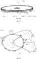
- the dehumidifying module assembly 20 includes a dehumidifying rotary plate 200 and an air outlet passage 203, and further includes a dehumidifying part 201 and a regenerating part 202.
- the dehumidifying rotary plate 200 may be formed as a rotating rotary plate (disc-shaped) or a rotating ring (circular-shaped) or formed as a planar structure being capable of reciprocating.
- the dehumidifying rotary plate 200 is formed by a material that can absorb moisture, and is configured to fully absorb moisture of the circulating airflow to turn the circulating airflow as a dry airflow.
- the dehumidifying module assembly 20 may be divided into at least two parts according to its function, i.e., a dehumidifying part 201 and a regenerating part 202, and the two parts are both sector-shaped and form a disc or ring shape after being combined together.
- the dehumidifying part 201 has a greater sector area than the regenerating part 202, such that more regions can be used to absorb moisture of the circulating airflow.
- a cooling cushion part may also be provided between the dehumidifying part 201 and the regenerating part 202, and is configured to cool part of the rotary plate heated by the regenerating part before the rotary plate enters the dehumidifying part, such that the moisture-absorbing efficiency is further improved.
- the region where the regenerating part 202 is located is preferably provided with a heating module that heats and dries the dehumidifying rotary plate 200 to remove its moisture, and a high-temperature and high-humidity airflow is generated.
- the dehumidifying rotary plate 200 is moved to the regenerating part 202 after it absorbs a large amount of water at the dehumidifying part 201, the dehumidifying rotary plate 200 is heated and dried to remove its moisture, such that the dehumidifying rotary plate 200 becomes dry, and can better absorb the moisture in the circulating airflow while rotating to the dehumidifying part 201.
- the regenerating part 202 can enable the dehumidifying rotary plate 200 to regenerate and restore its moisture-absorbing function.
- the dehumidifying rotary plate 200 allows the circulating airflow to pass through, the dehumidifying rotary plate 200 at the dehumidifying part 201 absorbs the moisture of the circulating airflow from the circulating fan 101; after the dehumidifying rotary plate 200 moves to the regenerating part 202, the moisture absorbed by the dehumidifying rotary plate 200 at the dehumidifying part 201 is removed, such that the dehumidifying rotary plate 200 can continuously maintain a dry state, thereby continuously absorbing the moisture in the circulating airflow.
- a filtering assembly 60 is provided at the upstream of an air intaking location of the circulating fan 101 and is preferably provided in the air inlet passage 102 to filter lint and impurities in the airflow flowing from the drum to the dehumidifying module assembly 20.
- the lint or impurities are prevented from entering the dehumidifying module assembly 20, especially from entering the dehumidifying rotary plate 200; otherwise, the lint or impurities block the dehumidifying rotary plate 200, which affects the dehumidifying effect.
- the lint adhered to the dehumidifying rotary plate 200 is brought into the regenerating part during the rotation process, the lint may be easily ignited because the regenerating part has a heating module.
- the drying device according to the present disclosure may be provided in various positions, and may, for example, be provided at the upper part, the rear and the lower part of the drum of the washing machine. Accordingly, the air inlet passage 102 of the drying device may be provided at a plurality of positions, such as the left rear side, right rear side, upper part, front side and the like of the drum of the washing machine.
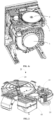
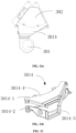
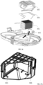
- FIG. 10 is a schematic structural diagram of a regenerating module assembly of an integrated washer-dryer according to the present application, where FIG. 10a is an assembly structural diagram of the regenerating module assembly and FIG. 10b is an exploded structural diagram of the regenerating module assembly.
- An air outlet (not shown) of the regenerating fan 301 is communicated with the heating module 302, and the regeneration airflow that is heated by the heating module 302 is transformed into a high-temperature and dry regeneration airflow to better dehumidify and dewater the regenerating part 202 of the dehumidifying rotary plate adjacent to the heating module 302.
- the heating module 302 is provided at the downstream of the regenerating fan 301, and is configured to heat up the regeneration airflow generated by the regenerating fan 301.
- the heating module 302 is provided in a region where the regenerating part 202 is located to further heat and dry the dehumidifying rotary plate 200 in the region of the regenerating part 202, such that the moisture absorbed by the dehumidifying rotary plate 200 is heated and evaporated into a high-temperature moist airflow.
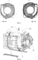
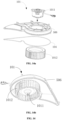
- FIG. 11 is a schematic diagram of a closed-loop regenerating and circulating structure of the regenerating module assembly of the integrated washer-dryer according to the present application.
- the condensing module assembly 40 is provided at the downstream of the regeneration air outlet 3012 and is communicated with the air inlet of the condensing module assembly 40; whereas the air outlet of the condensing module assembly 40 is communicated with the regeneration air inlet 3011.
- a circulating path of the regeneration airflow is as follows: an air outlet of the condensing module assembly 40 (low-temperature and dry)-the regeneration air inlet 3011-the regenerating fan 301-an air outlet of the regenerating fan 301-the heating module 302 (high temperature)-the regenerating part 202 (high-temperature and high-humidity)-the regeneration air outlet 3012-an air inlet of the condensing module assembly 40-the condensing module assembly 40 (low-temperature and dry). Finally, the regeneration airflow flows back to the air inlet of the regenerating fan, i.e., the regeneration air inlet 3011.
- the condensing module assembly 40 herein is configured to condense the high-temperature and high-humidity regeneration airflow output from the regeneration air outlet 3012 to form a low-temperature and dry airflow.
- the condensate water generated from the condensation of the high-temperature and high-humidity regeneration airflow in the condensing module assembly 40 is discharged via the condensate water outlet of the condensing module assembly 40.
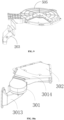
- FIG. 12 is a schematic structural diagram of a regeneration air inlet connector according to an embodiment of the present disclosure, where FIG. 12a is a schematic diagram of a connecting structure of the regeneration air inlet connector, and FIG. 12b is a schematic diagram of an internal structure of the regeneration air inlet connector.
- the air inlet of the regenerating fan 301 is also known as a regeneration air inlet 3011 of the regenerating module assembly 30.
- the regeneration air inlet connector 3013 is formed as an airduct member having two ventilation ports, and includes a horizontal port 3013-3 with a horizontal opening and a vertical port 3013-4 with a vertical opening. Accordingly, the regeneration air inlet connector 3013 is wholly formed in a curved shape transitioning from the horizontal opening to the vertical opening, so as to communicate with the condensing module assembly 40 and the regenerating fan 301 more compactly and hermetically to change directions of the airflow.
- the regeneration air inlet connector 3013 may be formed integrally, or may optionally be formed as upper and lower parts 3013-1 and 3013-2 as shown in FIG. 12b , the two parts being machined and finished separately and then formed as whole via a welding process.
- the upper part 3013-1 is communicated with the housing of the condensing module assembly 40
- the lower part 3013-2 is communicated with a condensing mounting region 503' of the lower housing of the drying device.
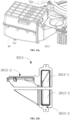
- the regeneration air outlet connector 3014 is preferably provided with two ports ventilating in the horizontal direction, and has an overall shape as a flared shape gradually expanding from a smaller port to a larger port.
- the smaller port 3014-3 is provided to be hermetically communicated with the regenerating fan 301 (air outlet), and the larger port 3014-4 is provided to be hermetically communicated with the regenerating part 202.
- the shape of the opening of the larger port 3014-4 matches the shape of the regenerating part 202 to achieve a hermetical communication therebetween.
- the larger port 3014-4 is also formed as a round-arc opening to match the regenerating part 202.
- the regenerating fan 301 outputs the low-temperature and dry airflow to the regenerating part 202 (a region where the heating module 302 is located) to take away and replace the high-temperature high-humidity airflow generated by the regenerating part 202, thereby reducing the temperature and humidity of the regenerating part 202 and regenerating and restoring the dehumidifying function of the regenerating part 202.
- the high-temperature and high-humidity airflow generated by the regenerating part 202 is conveyed to the atmosphere or the condenser 401 via the regeneration air outlet 3012.
- the regeneration air outlet connector 3014 may be formed integrally, or may optionally be formed as upper and lower parts 3014-1 and 3014-2 as shown in FIG. 13b , the two parts being machined and finished separately and then formed via a welding process.
- the upper part 3014-1 is communicated with the upper housing of the regenerating part 202
- the lower part 3014-2 is communicated with the rotary plate mounting region 501' of the lower housing of the drying device.
- the regeneration air outlet connector 3014 adopts a specific shape to achieve effects of adjusting the orientation of the airduct, diffusing and sealing while ensuring the manufacturability of the regeneration air outlet connector 3014.
- the air inlet passage 102 is communicated with the drum A and the circulating fan 101, such that moist air in the drum A of the integrated washer-dryer can enter the circulating fan 101.
- the air inlet passage 102 is provided in an approximately vertical direction, such that the moist air in the drum A of the integrated washer-dryer enters the circulating fan 101 from down to up.
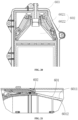
- the air inlet passage 102 is connected to the drum of the washing machine via a flexible pipe such as a corrugated hose, such that the vibration of the drum of the washing machine can be prevented from being transmitted to the drying device, thereby avoiding vibration of the drying device, as shown in FIG. 15 .
- the lower housing assembly of the circulating module assembly is connected to the drum via a flexible connection such as a corrugated pipe, such that the vibration of the drum can be prevented from being transmitted to the rigid air inlet passage 102 and further to the entire drying device.
- FIG. 15 exemplarily shows a mounting way.
- a corrugated pipe 1021 at the position of the air inlet passage 102 is fixed to a pressing plate 1022 via a locating pin, such that the corrugated pipe 1021 can be fixed by fixing the pressing plate via a screw, and a flexible connection formed between the housing of the circulating fan and the drum is implemented by the corrugated pipe.
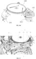
- FIG. 17 is a schematic diagram of a water supplying assembly of an integrated washer-dryer according to the present application.
- the water-supplying assembly C of the integrated washer-dryer includes one water inlet C0, a plurality of water-supplying ports (e.g., a drum water-supplying port C1, a filter screen water-supplying port C2, a condenser water-supplying port C3, and the like), and one water outlet C4.
- a plurality of water-supplying ports e.g., a drum water-supplying port C1, a filter screen water-supplying port C2, a condenser water-supplying port C3, and the like
- one water outlet C4 e.g., a drum water-supplying port C1, a filter screen water-supplying port C2, a condenser water-supplying port C3, and the like
- the water inlet C0 is communicated with an external water source, such that water from the external water source is supplied to the integrated washer-dryer as a whole, where the water supplying includes supplying water to the drum for washing, supplying water to the filter screen for self-cleaning and supplying water to the condenser for condensing.
- the water outlet C4 is communicated with the external space to discharge wastewater generated by the integrated washer-dryer to the outside of the machine body.
- the one water inlet C0 of the water-supplying assembly C is connected to a tap water pipe, and is communicated with three water-supplying ports C1, C2 and C3, which are a drum water-supplying port C1 for supplying water to the drum of the washing machine and/or a cleaning fluid cartridge, a filter screen water-supplying port C2 for supplying water to a self-cleaning spray pipe of the filter screen, and a condenser water-supplying port C3 for supplying low-temperature water to the condenser to provide condensing water for the regeneration and circulation of the drying device.
- three water-supplying ports C1, C2 and C3 which are a drum water-supplying port C1 for supplying water to the drum of the washing machine and/or a cleaning fluid cartridge, a filter screen water-supplying port C2 for supplying water to a self-cleaning spray pipe of the filter screen, and a condenser water-supplying port C3 for supplying low-temperature water to the condenser to provide condensing water for the regeneration and
- the aforesaid water-supplying assembly C is provided with a solenoid valve switch that can control the opening and closing of the plurality of water-supplying ports, respectively, thereby enabling to control the specific time in supplying water to the drum, supplying water to the cleaning fluid cartridge, and supplying water for condensation or filter screen cleaning.
- FIG. 18 is a schematic diagram of connection for the air inlet passage of the drying device of the washing machine.
- the air inlet passage 102 of the drying device communicates the circulating fan 101 with the drum A.
- the moist air in the drum is introduced to the dehumidifying part 201 of the dehumidifying rotary plate 200 for dehumidification.
- a filtering assembly 60 is provided at the upstream of air intaking of the circulating fan 101 and is preferably provided in the air inlet passage 102 for filtering lint and impurities in the air flowing from the drum to the dehumidifying module assembly 20.
- the lint or impurities are prevented from entering the dehumidifying module assembly 20, especially from entering the dehumidifying rotary plate 200; otherwise the lint or impurities block the dehumidifying rotary plate 200, which affects the dehumidifying effect.
- the lint adhered to the dehumidifying rotary plate 200 is brought into the regenerating part during the rotation process, the lint may be easily ignited because the regenerating part has a heating module.
- the internal structure of the filtering assembly 60 will be described in detail below.
- FIG. 19 is a schematic structural diagram of a filtering assembly according to the present disclosure.
- the filtering assembly 60 includes a filter screen 601, at least one cleaning nozzle 602, and a nozzle water-supplying pipe 603, which are provided sequentially in the air inlet passage 102 along an air intaking direction, such that the air from the drum of the washing machine first passes through the filter screen 601 to filter out the lint and impurities contained in the air.
- the cleaning nozzle 602 is configured to spray clean water to clean the filter screen 601 to remove any lint or impurity adhered to the filter screen 601, such that the filtering capability of the filter screen 601 is restored to continuously filter the air from the drum.
- the nozzle water supplying pipe 603 is communicated with the filter screen water-supplying port C2 to provide clean water from an external water source to the cleaning nozzle 602.
- the filtering assembly 60 is further provided with a clean water flow passage (not shown).
- the clean water flow passage is preferably provided on a side of a non-filtering surface 6012 of the filter screen 601 and is communicated with the water outlet C4 of the washing machine.
- the self-cleaning water flows from the nozzle water supplying pipe 603 to the nozzle and then rinses a filtering surface 6011 of the filter screen to flush out the lint and impurities adhered to the filter screen. Then, the self-cleaning water flows, after flushing the filter screen, to the water outlet C4 of the washing machine and is discharged to the outside of the machine body.
- a separate water outlet C5 may be provided in the clean water flow passage to allow the self-cleaning water to be discharged independently to the outside of the machine body of the washing machine.
- the cleaning nozzle 602 is provided to taper into a flat shape from the nozzle water supplying pipe 603 to the filter screen 601.
- the width of the filter screen 601 basically covers the entire width of the air inlet passage 102 to improve the filtering effect.
- the cleaning water is enabled to flow to cover the entire width of the filter screen 601, thereby improving the self-cleaning effect of the filter screen 601.
- the filter screen 601 is formed in the air inlet passage 102 as an inclined extending shape, and the shape has the following advantages. Firstly, a filtering area of the air can be increased, such that the airflow passing efficiency will not be affected by the blocking caused by a small filtering area. Secondly, the dirt, if any, left during the self-cleaning process of the filter screen will not affect the subsequent airflow passing efficiency.
- an inclination angle of the filter screen 601 relative to the inner wall of the air inlet passage 102 may be provided in a range of 0-80°, preferably in a range of 5-45°, such that the self-cleaning of the filter screen can correspondingly have a rather great flushing area, thereby effectively preventing the lint and the like from being embedded in holes of the filter screen and from increasing the difficulty in flushing off.
- the moist airflow from the drum first passes through a surface of the filter screen (which can be defined as a filtering surface for intercepting lint and the like), and then flows upward after passing through the filter screen to reach the dehumidifying part 201 of the dehumidifying rotary plate 200.
- the self-cleaning water flow is sprayed via the cleaning nozzle 602 to flush the filtering surface of the filter screen 601 to flush out lint and the like attached thereto.
- the cleaning nozzle 602 may be provided at the non-filtering surface 6012 of the filter screen.
- the nozzle 602 may spray to the filter screen some water with a certain flow velocity (i.e., a water flow that can form a certain impact on the filter screen) against the flowing direction of the airflow, such that the water is sprayed from the non-filtering surface 6012 to the filter screen to wash away the lint attached to the filter screen.
- a certain flow velocity i.e., a water flow that can form a certain impact on the filter screen
- the arrow 1 indicates the flowing direction of the filter screen self-cleaning water
- arrow 2 indicates the flowing direction of the moist airflow from the drum.
- the cleaning nozzle 602 herein is provided to go against the air intaking direction, such that the self-cleaning water sprayed from the cleaning nozzle 602 flows against the air intaking direction, and the lint or impurities on the filter screen 601 can be thereby cleaned more thoroughly.
- the self-cleaning water in this embodiment flows against the air intaking direction, and may either flow along the filtering surface 6011 of the filter screen or along the non-filtering surface 6012 of the filter screen.
- the water flow velocity and flow rate may be relatively small when flushing the filtering surface, and may be relatively large when flushing the non-filtering surface 6012.
- the water flowing direction is at an angle of, for example, 40-90° to an extending surface of the filter screen, facilitating flushing of the lint trapped in holes of the filter screen.
- FIG. 20 is a schematic structural diagram of a nozzle of the filtering assembly according to the present disclosure.
- the cleaning nozzle 602 includes a connecting part 6021 connected to the nozzle water-supplying pipe 603, and a duckbill-shaped extending part 6022.
- the connecting part 6021 is configured to connect to the nozzle water-supplying pipe 603; and the extending part 6022 extends from the connecting part and gradually decreases in the height direction and gradually increases in the width direction, thereby forming an approximately flat downward water flow.
- a width of the extending part 6022 (water outlet) of the cleaning nozzle 602 is provided to be greater than or slightly less than the width (e.g., 90% of the width) of the filter screen to clean the filter screen as fully as possible.
- FIG. 21 is a schematic positional diagram of a nozzle of a filtering assembly according to the present disclosure.
- the cleaning nozzle 602 may be provided facing two side surfaces of the filter screen 601 (including the filtering surface 6011 and the non-filtering surface 6012 opposite the filtering surface), such that the two side surfaces of the filter screen can be cleaned and sprayed simultaneously. More preferably, two cleaning nozzles 602 facing the filtering surface 6011 and the non-filtering surface 6012 of the filter screen, respectively, may be provided to clean the two side surfaces of the filter screen simultaneously, thereby improving the cleaning efficiency and cleaning effect.
- one cleaning nozzle 602 to spray water and clean the non-filtering surface 6012 first, and then activate the other cleaning nozzle 602 to spray water and clean the filtering surface 6011 after a provided time; or the two cleaning nozzles may be activated simultaneously. In this way, the cleaning effect of the filter screen can be further improved.
- the cleaning nozzle 602 is generally provided to activate cleaning of the filter screen when the drying device stops working, such that the moisture content of the air in the air inlet passage 102 can be prevented from being increased when the cleaning nozzle sprays water and cleans the filter screen, thereby preventing adverse influence on the operation of the drying device.
- the cleaning nozzle 602 is provided to start spraying water and cleaning before the drying device starts working, such that the lint and impurities on the filter screen are all removed before air is fed from the drum and the drying device is started to perform drying.
- the water spraying and cleaning duration of the cleaning nozzle 602 may be of a preset time length; or a detecting module may be provided to detect whether the lint and impurities on the filter screen 601 have been removed completely, and controls the cleaning nozzle 602 to stop spraying water and cleaning if the detection result is "yes.”
- a cleaning water detecting device may be provided at the position of the cleaning nozzle and configured to detect parameters, such as a flow rate and velocity of the cleaning water, and a cleaning state of the filter screen, and send the parameters to the control device, such that the control device is enabled to control the spraying or closing, spraying frequency, spraying velocity and the like of the cleaning water.
- FIG. 22 is a schematic positional diagram of a condensing nozzle of a filtering assembly according to the present disclosure.
- the filtering assembly 60 is further provided with a condensing nozzle 605, which is provided on the outer wall of the air inlet passage 102 to achieve pre-condensing by spraying water onto the outer wall of the air inlet passage 102.
- Moist air that enters the drying device from the drum via the air inlet passage 102 contains a large amount of moisture, and generally has the room temperature or a relatively high temperature.
- the moisture in the circulating airflow can be condensed into liquid water in advance and discharged from the machine body via a preset flow passage (e.g., a sleeve is provided outside the outer wall of the air inlet passage 102 to form a space for the condensing water flow passage).
- a preset flow passage e.g., a sleeve is provided outside the outer wall of the air inlet passage 102 to form a space for the condensing water flow passage.
- the pre-condensing nozzle 605 may directly inject water to the inner wall of the air inlet passage 102, such that the water flows slowly down the inner wall to keep the wall of the air inlet passage at a low temperature, thereby allowing to condense the airflow flowing through the air inlet passage.
- the condensing effect of the air inlet passage 102 of the air outlet of the drum is implemented by maintaining a continuous low temperature of the pipe wall by slowly spraying water onto the outer wall of the pipe of the air inlet passage 102 via the condensing nozzle 605, thereby achieving condensation of the hot and moist airflow flowing through the pipe. Therefore, the condensing nozzle 605 generally starts spraying water for condensation when the drying device starts working, and stops working when the drying of clothes in the drum is completed and the drying device stops working.
- the condensing nozzle 605 may start working at the early stage of the drying operation, and stop at the later stage, because the precondensation as started can reduce the moisture content in the airflow, which is rather high at the early stage, and thus, the drying efficiency can be improved.
- an outer pipe may sleeve the air inlet passage 102, and the condensing nozzle 605 is provided between the outer pipe and the outer wall of the air inlet passage 102, such that a water flow space is formed between the outer wall of the pipe of the air inlet passage 102 and the inner wall of the outer pipe sleeved thereto.
- the condensate water may be directed to be discharged from the washing machine via a separate water discharging pipe, or to flow into the outer tub of the drum and merge with the water outlet passage of the drum to be discharged via the water discharging pipe of the washing machine, such that the water can be sprayed to the outer wall of the pipe while ensuring that no such condensate water is left behind.
- a condensate water detecting device is further provided at the position of the condensing nozzle, configured to detect a flow rate and velocity of the condensate water and send the flow rate and velocity to the control device, allowing the control device to control the spraying or closing, spraying velocity, and the like of the condensate water.
- a removable filter screen 601 may be provided in the air inlet passage 102, such that a user can remove and clean the filter screen 601 and then assemble it into the air inlet passage 102.
- the path of the air inlet passage 102 may be provided to pass through a removable box provided in the front-end panel or side panel of the washing machine, and the filter screen 601 is provided in the removable box, such that the user can easily open the box, take out and clean the filter screen, and then close the box after putting the filter screen back.
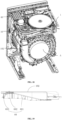
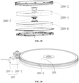
- FIG. 23 is a schematic structural diagram of a dehumidifying module assembly according to the present disclosure.
- a main part of the drying device of the present disclosure is the dehumidifying module assembly 20, and the dehumidifying module assembly 20 sequentially includes the rotary plate upper housing 505, the dehumidifying rotary plate 200, and the rotary plate lower housing 501 from top to bottom.
- the rotary plate lower housing 501 and the rotary plate upper housing 505 are fixed to each other by means of buckles, bolts, glue and so on.
- the housing component of the dehumidifying module assembly 20 further includes a lower housing regenerating region assembly part 202-2 and an upper housing regenerating region assembly part 202-3, which are configured to at least separate the regenerating part 202 from the dehumidifying part 201 of the dehumidifying rotary plate and maintain a relative sealing therebetween. That is, the airflow from the regenerating part 202 may flow to the dehumidifying part 201 as little as possible by passing through the separator, and the airflow from the dehumidifying part may flow to the regenerating part as little as possible by passing through the separator.
- FIG. 24 is an exploded structural diagram of a sealing package of the dehumidifying module assembly.
- the dehumidifying module assembly 20 is further provided with at least one flexible roller 200-4.
- the flexible roller 200-4 is provided on the inner side of the rotary plate housing, and is in rolling contact with the auxiliary rotating ring 200-3 to assist the normal rotation of the dehumidifying rotary plate and reduce the friction.
- the flexible roller 200-4 is flexible and deformable.
- the flexible roller 200-4 may be compressed to be deformed by the auxiliary rotating ring 200-3, and the pressure between the auxiliary rotating ring and the flexible roller 200-4 will cause no friction to the rotation of the rotary plate.
- the vibration damping structure of the molecular sieve 200-1 includes a circumferential vibration damping member 200-6 and/or a central vibration damping member 200-7, which will be respectively described in detail below.
- circumferential damping and/or end surface damping of the molecular sieve 200-1 is not necessarily provided simultaneously, and only one of the vibration damping structures is enough if the one damping structure can provide the desired vibration damping effect.
- the molecular sieve 200-1 of the dehumidifying rotary plate 200 is formed by a moisture-absorbing material, and properties of the material such as moisture adsorption, moisture evaporation, sterilization, and mechanical stability need to be considered comprehensively.
- the molecular sieve 200-1 of the present disclosure can be selected from one of the following materials: lithium chloride, silica gel, modified silica gel, zeolite, active alumina, 13X (sodium X type) molecular sieve, and the like.
- the dehumidifying module assembly 20 is further provided with a driving device.
- the driving device includes a driving motor and a transmission component, and is configured to drive the dehumidifying rotary plate 200 to rotate.
- a gear-like driving wheel 200-2 sleeves the periphery of the dehumidifying rotary plate 200
- a peripheral transmission gear 207-2 preferably sleeves a power shaft of the peripheral driving motor 207-1 and is provided to rotatably engage with a gear of the driving wheel 200-2, so as to drive the dehumidifying rotary plate 200 to rotate under the drive of the peripheral driving motor 207-1.
- the driving motor 207-1, the peripheral transmission gear 207-2, and the driving wheel 200-2 may be in transmission connection with each other by a drive belt such as a gear rack, a pulley belt and the like.
- the central driving device 208 (not shown) is rotatably provided in the center of the dehumidifying rotary plate 200, and is configured to drive the dehumidifying rotary plate 200 to rotate in a center-driving manner.
- the central driving device 208 includes a central driving motor 208-1 and a central transmission shaft 208-2.
- the periphery of the dehumidifying rotary plate 200 may be provided with no gear-like driving wheel 200-2, but the central transmission shaft 208-2 is fixedly connected to the center of the dehumidifying rotary plate 200 and driven by the central driving motor 208-1 to thereby drive the dehumidifying rotary plate 200 to rotate.
- an external gear may be fixedly provided on the central transmission shaft 208-2, and an internal gear may be provided in a center hole of the dehumidifying rotary plate 200. The internal and external gears are engaged with each other closely to enable the central driving motor 208-1 to drive the dehumidifying rotary plate 200 through the central transmission shaft 208-2.
- FIG. 31 is a schematic structural diagram of a flexible roller of the dehumidifying module assembly according to an embodiment of the present disclosure.
- At least one flexible roller 200-4 is provided along the periphery of the dehumidifying rotary plate 200 to assist the normal motion (rotation or movement) of the dehumidifying rotary plate and reduce friction.
- the flexible roller 200-4 is provided on the inner side of the rotary plate housing and is in rolling contact with the auxiliary rotating ring 200-3.
- the flexible roller 200-4 may be provided on an outward protruding mounting part on the inner ring of the rotary plate lower housing 501.
- roller tracks or track slots can be provided on the rotary plate housing no matter whether the flexible rollers 200-4 are provided or not.
- the track slot may restrict the dehumidifying rotary plate 200 in either the center or all surrounding directions, which allows the dehumidifying rotary plate 200 to be more stably kept in a preset position.
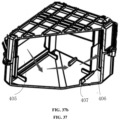
- FIG. 32 is a schematic structural diagram of an auxiliary roller of a dehumidifying module assembly according to an embodiment of the present disclosure.
- the auxiliary roller 200-8 is formed as a non-deformable rigid roller with a constant diameter during the motion.
- the heating module 302 is provided in the upper housing regenerating region 505-2 of the rotary plate upper housing 505 and is provided separately from the rotary plate upper housing 505.
- the heating module 302 is hermetically isolated from the rotary plate upper housing 505 with a thermal insulating material.
- a first sealing member 302-3 is provided between the heating module 302 and the rotary plate upper housing 505, and is provided along an external contour of the heating module 302.
- the first sealing member 302-3 is preferably formed by a thermal insulating or adiabatic material for isolating the heat transfer between the heating module 302 and the rotary plate upper housing 505.
- a second sealing member 302-4 is further provided on the first sealing member 302-3 to achieve the thermal insulating and collision cushioning between the heating module 302 and the rotary plate upper housing 505.
- the second sealing member 302-4 is made of a variable gel material such as foam, silicone or soft rubber, covers the first sealing member 302-3, and is provided along an external contour of the heating module 302 to achieve fixing and thermal insulating as well as cushioning the contact collision between the heating module 302 and the rotary plate upper housing 505.
- the rotary plate upper housing 505 may be deformed or scalded over time if the heating module is in direct contact with the rotary plate upper housing 505.
- a temperature transfer cushion region is formed by providing the first sealing member 302-3 and the second sealing member 302-4 between the rotary plate upper housing 505 and the heating module 302.
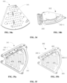
- FIG. 34 is a schematic structural diagram of a mesh plate of a heating module of a drying module assembly according to the present disclosure.
- FIG. 34a is a schematic structural diagram of a mesh plate serving as an air outlet of the heating module
- FIG. 34b is a schematic structural diagram of an air inlet of the heating module.
- the rotary plate upper housing 505 is formed into a disc shape, with a small sector-shaped region accommodating the separated heating module 302.
- a heater air inlet 302-1 is provided at the periphery of the heating module 30 and is communicated with the regenerating fan 301 to receive a dry regeneration air from the regenerating fan 301 and heat the air as a high-temperature and dry regeneration air.
- the heating module 302 is of a sector structure and includes a space formed by the upper and lower walls and two side walls along the radius direction.
- the heating module 302 includes a mesh plate 303 provided at the heater air outlet 302-2, a heater 304 disposed below the mesh plate 303, and a thermostat 305 extending outward from one of the side walls of the lower wall.
- the heating module 302 is communicated with the regenerating fan 301.
- the regeneration air enters the internal space of the heating module 302 via the heater air inlet 302-1 of the heating module 302, flows through the mesh plate 303 via the heater air outlet 302-2, then flows downward through the heater 304 via the air holes in the mesh plate 303, and finally flows to the rotary plate part of the regenerating part after being heated by the heater 304, thereby achieving the effect of heating and dehydrating the rotary plate part of the regenerating part.
- the diameters of the plurality of air holes in the mesh plate 303 preferably gradually become smaller or tend to become smaller along the periphery of the heating module 302 toward the center of the heating module 302. Because when the regeneration air enters via the heater air inlet 302-1 at the periphery of the heating module 302, the air holes having a larger diameter can facilitate the passing of the regeneration air having a relatively high air velocity; whereas the regeneration air may have a lower air velocity since the space of the heating module 302 gradually becomes narrower at the position close to the center of the heating module 302, and the air holes having a smaller diameter can allow the regeneration air to pass through the air holes as much as possible.
- FIG. 35 is a schematic structural diagram of a heater of a heating module of a drying module assembly according to the present disclosure; where FIG. 35a is a schematic diagram of relative positions of the heater and the mesh plate, and FIG. 35b is a schematic diagram of a layout structure of the heater.
- the heater 304 is provided directly below the air holes and slightly offsets toward the radius extending direction of the heating module.
- the air may have a certain velocity toward the radius direction indicated by the arrow.
- a little offset will allow the air passing through the air holes to face toward the heater, thereby improving the heating efficiency of airflow by the heater.
- a thermostat mounting part is provided to extend outward from one of the side walls of the heating module 302, and a thermostat 305 is mounted in the thermostat mounting part to monitor the temperature of the heater or the temperature of the airflow flowing out of the mesh plate 17.
- a heat-conducting sheet 305-1 is provided on the thermostat mounting part.
- the thermostat 305 is then provided inside the heat-conducting sheet, which means that the heat-conducting sheet 305-1 wraps around the thermostat 305 to conduct the temperature of the heater to the heat-conducting sheet 305-1 first by means of heat conduction, such that the thermostat 305 can directly detect the temperature of the heat-conducting sheet 305-1 and the air temperature inside the heating module can be monitored stably.
- the air carrying heat forms an eddy or turbulent flow in the space of the heating module, which causes the region to have an unstable temperature.
- the temperature detected by the thermostat 305 will be dynamic and very unstable, which is not conducive to effective control of the heater 304.
- FIG. 1 further shows a cooling water inlet 401-1, a cooling water outlet 401-2, and a condensate water outlet 401-3 of the condenser 401.
- the cooling water inlet 401-1 is connected to an external cold water source, and the cooling water outlet 401-2 is optionally communicated with the water outlet of the drum.
- the cooling water inlet 401-1 and cooling water outlet 401-2 cooperate with each other to provide the cooling water for condensation to a condenser pipeline and discharged the water from the condenser pipeline.
- the condensate water outlet 401-3 is configured to condense the water in the moisture desorbed from the dehumidifying rotary plate into liquid water and discharge the liquid water from the condenser housing.
- the condensing module assembly includes a condenser 401, a condenser upper housing 402, a condenser lower housing 403, and, preferably, a sealing member 404.
- the condenser fits into the lower condenser housing 403 by means of retaining bars and limiters, and the condenser upper housing squeezes down the sealing members 404 around the condenser to achieve a sealing effect.
- a recess is provided on the condenser upper housing 402 or the condenser lower housing 403 (e.g., on the condenser lower housing 403), and the other housing is provided with a projection.
- the recess may accommodate the sealing member 404 (e.g., a sealing gasket), and the sealing is achieved by pressing the projection into the recess.
- the air flowing direction of the condensing cycle is as follows.
- the high-temperature and high-humidity air enters the condensing region where the condenser 401 is located from the condenser air inlet 405, becomes the dry air after being condensed and dehumidified, and then flows out of the condenser via the condenser air outlet 406.
- part of the moist air may flow directly from the bottom of the condenser to the condenser air outlet 406 without passing through the condenser 401.
- this part of the moist air fails to be condensed, thereby causing a poor condensing and drying effect.
- a pre-condensing module assembly between the air outlet of the drum and the dehumidifying rotary plate (e.g., in the air inlet passage 102) to condense the hot and moist airflow having a relatively high temperature once to reduce the water content. Then, the moisture-absorbing processing is preformed again after the airflow enters the dehumidifying rotary plate.
- the pre-condensing module assembly may be formed as a separate condensing module assembly, and its condenser air inlet and condenser air outlet are communicated with the air outlet of the drum and the air inlet of the circulating fan, respectively.
- the pre-condensing module assembly may be in a structure of a condensing sleeve.
- the condensing sleeve envelopes the air outlet pipe of the drum, such that a water flow space can be formed between the outer wall of the air outlet pipe of the drum and the inner wall of the condensing sleeve.
- the pipe wall is kept at a continuous low temperature by slowly spraying water onto the outer wall of the air outlet pipe of the drum via the above condensing nozzle, thereby enabling the hot and moist air flowing through the pipe to be condensed into water.
- the cooling water in the condensing sleeve may flow to the outer tub of the drum or to a water outlet pipe of the washing machine.
Landscapes
- Engineering & Computer Science (AREA)
- Textile Engineering (AREA)
- Chemical & Material Sciences (AREA)
- Analytical Chemistry (AREA)
- General Chemical & Material Sciences (AREA)
- Oil, Petroleum & Natural Gas (AREA)
- Chemical Kinetics & Catalysis (AREA)
- Detail Structures Of Washing Machines And Dryers (AREA)
- Drying Of Gases (AREA)
- Drying Of Solid Materials (AREA)
- Control Of Washing Machine And Dryer (AREA)
- Main Body Construction Of Washing Machines And Laundry Dryers (AREA)
Applications Claiming Priority (3)
| Application Number | Priority Date | Filing Date | Title |
|---|---|---|---|
| CN202111023112.5A CN113981647A (zh) | 2021-09-01 | 2021-09-01 | 一种洗烘一体机 |
| CN202111450553 | 2021-11-30 | ||
| PCT/CN2022/116387 WO2023030421A1 (zh) | 2021-09-01 | 2022-08-31 | 一种烘干装置及洗烘一体机 |
Publications (2)
| Publication Number | Publication Date |
|---|---|
| EP4397804A1 true EP4397804A1 (de) | 2024-07-10 |
| EP4397804A4 EP4397804A4 (de) | 2025-08-20 |
Family
ID=83438804
Family Applications (5)
| Application Number | Title | Priority Date | Filing Date |
|---|---|---|---|
| EP22863529.8A Pending EP4386130A4 (de) | 2021-09-01 | 2022-08-31 | Wäschebehandlungsvorrichtung |
| EP22863556.1A Pending EP4397804A4 (de) | 2021-09-01 | 2022-08-31 | Trocknungsvorrichtung und integrierte wasch- und trocknungsmaschine |
| EP22863510.8A Pending EP4394120A4 (de) | 2021-09-01 | 2022-08-31 | Integrierter waschtrockner |
| EP22777000.5A Pending EP4396403A1 (de) | 2021-09-01 | 2022-09-01 | Trocknungssystem und waschmaschinen damit |
| EP23858522.8A Pending EP4582611A1 (de) | 2021-09-01 | 2023-01-17 | Kleidungsbehandlungsausrüstung |
Family Applications Before (1)
| Application Number | Title | Priority Date | Filing Date |
|---|---|---|---|
| EP22863529.8A Pending EP4386130A4 (de) | 2021-09-01 | 2022-08-31 | Wäschebehandlungsvorrichtung |
Family Applications After (3)
| Application Number | Title | Priority Date | Filing Date |
|---|---|---|---|
| EP22863510.8A Pending EP4394120A4 (de) | 2021-09-01 | 2022-08-31 | Integrierter waschtrockner |
| EP22777000.5A Pending EP4396403A1 (de) | 2021-09-01 | 2022-09-01 | Trocknungssystem und waschmaschinen damit |
| EP23858522.8A Pending EP4582611A1 (de) | 2021-09-01 | 2023-01-17 | Kleidungsbehandlungsausrüstung |
Country Status (9)
| Country | Link |
|---|---|
| US (4) | US20240384455A1 (de) |
| EP (5) | EP4386130A4 (de) |
| JP (6) | JP2024530799A (de) |
| KR (6) | KR20240035642A (de) |
| CN (16) | CN115726133A (de) |
| AU (6) | AU2022336912A1 (de) |
| CA (3) | CA3230573A1 (de) |
| TW (13) | TWI854293B (de) |
| WO (6) | WO2023030375A1 (de) |
Families Citing this family (12)
| Publication number | Priority date | Publication date | Assignee | Title |
|---|---|---|---|---|
| CN113981647A (zh) * | 2021-09-01 | 2022-01-28 | 北京石头世纪科技股份有限公司 | 一种洗烘一体机 |
| CA3230573A1 (en) * | 2021-09-01 | 2023-03-09 | Xing Li | Laundry treating device |
| JP2025527812A (ja) * | 2022-08-31 | 2025-08-22 | ナンジン・ロボロック・イノヴェーション・テクノロジー・カンパニー・リミテッド | 乾燥モジュールおよび洗濯乾燥一体型洗濯機 |
| KR20250060251A (ko) * | 2022-08-31 | 2025-05-07 | 선전 로보락 이노베이션 테크놀러지 컴퍼니 리미티드 | 식기 처리 장치 |
| CN118360769A (zh) * | 2023-01-17 | 2024-07-19 | 深圳洛克创新科技有限公司 | 一种过滤器清洁装置、衣物处理设备及其控制方法 |
| CN119571573A (zh) * | 2023-08-31 | 2025-03-07 | 南京石头创新科技有限公司 | 供水控制方法及装置、衣物处理设备和存储介质 |
| WO2025045095A1 (zh) * | 2023-08-31 | 2025-03-06 | 南京石头创新科技有限公司 | 衣物处理设备 |
| CN119571591A (zh) * | 2023-08-31 | 2025-03-07 | 南京石头创新科技有限公司 | 衣物处理设备 |
| WO2025067309A1 (zh) * | 2023-09-26 | 2025-04-03 | 南京石头创新科技有限公司 | 吸湿构件、烘干模组和衣物处理设备 |
| WO2025232776A1 (zh) * | 2024-05-07 | 2025-11-13 | 南京石头创新科技有限公司 | 烘干模组和衣物处理设备 |
| CN118846697B (zh) * | 2024-09-24 | 2025-01-28 | 苏能(锡林郭勒)发电有限公司 | 一种褐煤机组烟气净化系统 |
| CN119265889A (zh) * | 2024-12-06 | 2025-01-07 | 珠海格力电器股份有限公司 | 用于洗衣机的烘干设备 |
Family Cites Families (84)
| Publication number | Priority date | Publication date | Assignee | Title |
|---|---|---|---|---|
| JPS58118796A (ja) * | 1982-01-06 | 1983-07-14 | 株式会社日立製作所 | 衣類乾燥機 |
| DE3626887A1 (de) * | 1986-08-08 | 1988-02-11 | Miele & Cie | Waeschebehandlungs- und spuelgeraet, herd o. dgl., mit einer entfeuchtungseinrichtung |
| JP2753291B2 (ja) * | 1988-12-14 | 1998-05-18 | 株式会社日立製作所 | 衣類乾燥機用水冷式熱交換器 |
| JP2806542B2 (ja) * | 1989-02-17 | 1998-09-30 | 株式会社日立製作所 | 衣類乾燥機 |
| JPH0510669A (ja) * | 1991-07-04 | 1993-01-19 | Matsushita Electric Ind Co Ltd | 衣類乾燥機 |
| JP3043126B2 (ja) * | 1991-08-28 | 2000-05-22 | 三洋電機株式会社 | 衣類乾燥機 |
| CN1139163A (zh) * | 1995-06-29 | 1997-01-01 | 上海家用空调器总厂 | 热泵加热制冷去湿内循环排湿干衣机 |
| JP2000051576A (ja) * | 1998-08-04 | 2000-02-22 | Sharp Corp | 洗濯機 |
| JP2000225288A (ja) * | 1999-02-04 | 2000-08-15 | Matsushita Electric Ind Co Ltd | 洗濯乾燥機 |
| JP2002340372A (ja) * | 2001-05-17 | 2002-11-27 | Matsushita Electric Ind Co Ltd | 除湿デバイス |
| JP4196075B2 (ja) * | 2003-04-11 | 2008-12-17 | パナソニック株式会社 | 洗濯乾燥機 |
| JP3650104B2 (ja) * | 2003-05-21 | 2005-05-18 | シャープ株式会社 | 衣類乾燥機 |
| JP2005021601A (ja) * | 2003-07-03 | 2005-01-27 | Toshiba Corp | 洗濯乾燥機 |
| KR20050012100A (ko) * | 2003-07-24 | 2005-01-31 | 삼성전자주식회사 | 세탁기용 건조장치 및 이를 포함한 세탁기 |
| WO2005012624A1 (en) * | 2003-07-30 | 2005-02-10 | John Edward Gough | Drying apparatus |
| CN1886628B (zh) * | 2003-09-29 | 2011-09-07 | 自推进研发专家公司 | 热泵式干衣机 |
| KR101235193B1 (ko) * | 2005-06-13 | 2013-02-20 | 삼성전자주식회사 | 세탁기 및 그 제어방법 |
| JP2007075241A (ja) * | 2005-09-13 | 2007-03-29 | Matsushita Electric Ind Co Ltd | 洗濯乾燥機 |
| JP4676291B2 (ja) * | 2005-09-22 | 2011-04-27 | パナソニック株式会社 | 衣類乾燥装置 |
| JP3920299B2 (ja) * | 2005-09-22 | 2007-05-30 | 松下電器産業株式会社 | 衣類乾燥装置 |
| JP2007098261A (ja) * | 2005-10-04 | 2007-04-19 | Matsushita Electric Ind Co Ltd | 除湿機 |
| JP2008029654A (ja) * | 2006-07-31 | 2008-02-14 | Sharp Corp | 洗濯乾燥機 |
| JP2008035958A (ja) * | 2006-08-02 | 2008-02-21 | Sharp Corp | 洗濯乾燥機 |
| JP4910607B2 (ja) * | 2006-10-02 | 2012-04-04 | パナソニック株式会社 | 除湿装置 |
| JP2008259665A (ja) * | 2007-04-12 | 2008-10-30 | Sharp Corp | ドラム式洗濯乾燥機 |
| KR20090001073A (ko) * | 2007-06-29 | 2009-01-08 | 엘지전자 주식회사 | 복합의류처리장치 |
| JP4423323B2 (ja) * | 2007-10-02 | 2010-03-03 | 日立アプライアンス株式会社 | ドラム式乾燥機及びドラム式洗濯乾燥機 |
| JP4559502B2 (ja) * | 2008-03-14 | 2010-10-06 | 三菱電機株式会社 | 除湿機 |
| JP2009240937A (ja) * | 2008-03-31 | 2009-10-22 | Panasonic Corp | 除湿装置 |
| JP4972612B2 (ja) * | 2008-05-30 | 2012-07-11 | 日立アプライアンス株式会社 | 洗濯機、および洗濯乾燥機 |
| JP2010167178A (ja) * | 2009-01-26 | 2010-08-05 | Mitsubishi Electric Corp | 洗濯乾燥機 |
| EP2246470B1 (de) * | 2009-04-28 | 2014-06-04 | Candy S.p.A. | Wasch- und Trockenmaschine |
| EP2471994B1 (de) * | 2011-01-04 | 2019-06-26 | Electrolux Home Products Corporation N.V. | Vorrichtung zum Wäschetrocknen |
| JP5345469B2 (ja) * | 2009-08-11 | 2013-11-20 | 象印マホービン株式会社 | 除湿機及びその運転制御方法 |
| JP5068295B2 (ja) * | 2009-09-24 | 2012-11-07 | シャープ株式会社 | 乾燥機 |
| JP4698750B2 (ja) * | 2009-09-24 | 2011-06-08 | シャープ株式会社 | 洗濯機及び乾燥機 |
| KR20140015234A (ko) * | 2010-06-02 | 2014-02-06 | 7142871 캐나다 인코포레이티드 | 표준 및 방폭형 제습용 마이크로파 재활성화 시스템 |
| JP2012029783A (ja) * | 2010-07-29 | 2012-02-16 | Sanyo Electric Co Ltd | 乾燥機 |
| US8572865B2 (en) * | 2010-10-29 | 2013-11-05 | General Electric Company | Apparatus and method for using a hybrid dryer tub for airflow improvement |
| JP2012161355A (ja) * | 2011-02-03 | 2012-08-30 | Toshiba Corp | 衣類乾燥機 |
| CN202116896U (zh) * | 2011-03-31 | 2012-01-18 | 无锡小天鹅股份有限公司 | 洗烘一体机的烘干冷凝装置 |
| US9487906B2 (en) * | 2011-04-05 | 2016-11-08 | Lg Electronics Inc. | Laundry machine and method for cleaning lint filter of laundry machine |
| CN102206916B (zh) * | 2011-06-23 | 2016-08-31 | 青岛海尔洗衣机有限公司 | 一种用于滚筒干衣的热泵烘干系统及控制方法 |
| CN102286872B (zh) * | 2011-07-12 | 2016-11-16 | 青岛海尔滚筒洗衣机有限公司 | 一种带热泵烘干和除湿功能的洗衣干衣机 |
| EP2549009B1 (de) * | 2011-07-21 | 2013-12-25 | Whirlpool Corporation | Verfahren zur Steuerung eines Wäschetrockners und Wäschetrockner mit solch einem Verfahren |
| CN103797174B (zh) * | 2012-04-06 | 2016-08-17 | Lg电子株式会社 | 衣物处理机 |
| US9140396B2 (en) * | 2013-03-15 | 2015-09-22 | Water-Gen Ltd. | Dehumidification apparatus |
| KR101579465B1 (ko) * | 2013-07-19 | 2015-12-23 | 엘지전자 주식회사 | 건조기 |
| JP6373020B2 (ja) * | 2014-03-06 | 2018-08-15 | シャープ株式会社 | 乾燥機 |
| CN105297372B (zh) * | 2014-07-31 | 2019-02-19 | 青岛海尔洗衣机有限公司 | 一种衣物烘干系统及烘干方法、洗衣干衣一体机、干衣机 |
| CN204491256U (zh) * | 2014-12-24 | 2015-07-22 | 珠海格力电器股份有限公司 | 干衣机及其调湿装置 |
| KR102053323B1 (ko) * | 2015-07-31 | 2019-12-06 | 주식회사 엘지화학 | 흡습 부재가 구비된 세탁기 |
| CN106917221B (zh) * | 2015-10-26 | 2019-12-27 | 东芝生活电器株式会社 | 衣物烘干机 |
| JP6619997B2 (ja) * | 2015-11-25 | 2019-12-11 | 日立グローバルライフソリューションズ株式会社 | 洗濯乾燥機 |
| CN105463812B (zh) * | 2015-12-30 | 2019-03-01 | Tcl家用电器(合肥)有限公司 | 洗烘一体机 |
| CN107447472B (zh) * | 2016-05-31 | 2019-09-17 | 无锡小天鹅电器有限公司 | 热泵安装盒及热泵干衣机或热泵洗干一体机 |
| KR20180014615A (ko) * | 2016-08-01 | 2018-02-09 | 엘지전자 주식회사 | 의류처리장치 |
| JP2018071901A (ja) * | 2016-10-31 | 2018-05-10 | 大阪瓦斯株式会社 | 乾燥システムおよびその運転方法 |
| CN108004733B (zh) * | 2016-10-31 | 2020-04-17 | 众智光电科技股份有限公司 | 烘衣机 |
| KR102613562B1 (ko) * | 2016-12-29 | 2023-12-14 | 엘지전자 주식회사 | 듀얼 타입 건조기 |
| KR102358922B1 (ko) * | 2017-06-22 | 2022-02-07 | 주식회사 경동나비엔 | 건조장치 및 건조방법 |
| CN109402988B (zh) * | 2017-08-16 | 2022-02-22 | 青岛海尔洗涤电器有限公司 | 烘干系统控制方法及衣物处理装置 |
| CN107663761B (zh) * | 2017-08-29 | 2019-12-10 | 珠海格力电器股份有限公司 | 衣物烘干判断方法和装置 |
| CN207159639U (zh) * | 2017-09-13 | 2018-03-30 | 赵正华 | 采用热泵加热和冷凝集水功能的干衣机 |
| JP6948235B2 (ja) * | 2017-11-28 | 2021-10-13 | 東芝ライフスタイル株式会社 | 衣類乾燥機 |
| CN110055730B (zh) * | 2018-01-18 | 2022-01-04 | 重庆海尔滚筒洗衣机有限公司 | 一种热泵干衣机及控制方法 |
| CN110106681B (zh) * | 2018-02-01 | 2024-09-27 | 青岛海尔洗护电器有限公司 | 一种风道转换装置及衣物处理装置 |
| JP2019150413A (ja) * | 2018-03-06 | 2019-09-12 | 日立グローバルライフソリューションズ株式会社 | 洗濯乾燥機 |
| JP2019187613A (ja) * | 2018-04-20 | 2019-10-31 | 東芝ライフスタイル株式会社 | 衣類乾燥機 |
| KR20190128469A (ko) * | 2018-05-08 | 2019-11-18 | 엘지전자 주식회사 | 의류 처리 장치 |
| CN111101351B (zh) * | 2018-10-26 | 2022-08-26 | 无锡小天鹅电器有限公司 | 烘干系统和衣物处理装置 |
| CN109629206B (zh) * | 2019-02-18 | 2023-11-28 | 珠海格力电器股份有限公司 | 烘干设备及该烘干设备的运行方法 |
| JP2021121262A (ja) * | 2020-01-31 | 2021-08-26 | 東芝ライフスタイル株式会社 | 衣類乾燥機 |
| CN212199700U (zh) * | 2020-05-20 | 2020-12-22 | 山东大成洗涤机械有限公司 | 一种洗烘一体机 |
| CN111926524B (zh) * | 2020-08-24 | 2024-08-27 | 长虹美菱股份有限公司 | 一种洗干一体机 |
| CN213896424U (zh) * | 2020-09-22 | 2021-08-06 | 云米互联科技(广东)有限公司 | 水气分离的换热组件及衣物烘干装置 |
| CN113605036B (zh) * | 2020-10-26 | 2024-09-10 | 松下家电(中国)有限公司 | 衣物处理设备的护理控制方法 |
| CN112709040A (zh) * | 2020-12-22 | 2021-04-27 | 珠海格力电器股份有限公司 | 一种多桶洗衣干衣一体机及其控制方法 |
| CN113418242A (zh) * | 2021-06-03 | 2021-09-21 | 重庆海尔空调器有限公司 | 无水加湿装置、空调器 |
| CN113584800B (zh) * | 2021-08-02 | 2022-09-27 | 珠海格力电器股份有限公司 | 一种内衣烘干方法及洗烘一体设备 |
| CA3230573A1 (en) * | 2021-09-01 | 2023-03-09 | Xing Li | Laundry treating device |
| CN113981647A (zh) * | 2021-09-01 | 2022-01-28 | 北京石头世纪科技股份有限公司 | 一种洗烘一体机 |
| CN114318814B (zh) * | 2021-12-07 | 2022-11-25 | 珠海格力电器股份有限公司 | 烘干风道、洗干一体机及烘干风道的控制方法 |
| CN114606745A (zh) * | 2022-03-09 | 2022-06-10 | 创维电器股份有限公司 | 一种干衣机的判干方法 |
-
2022
- 2022-08-31 CA CA3230573A patent/CA3230573A1/en active Pending
- 2022-08-31 JP JP2024514384A patent/JP2024530799A/ja active Pending
- 2022-08-31 US US18/688,706 patent/US20240384455A1/en active Pending
- 2022-08-31 CN CN202211059234.4A patent/CN115726133A/zh active Pending
- 2022-08-31 US US18/688,711 patent/US20250003137A1/en active Pending
- 2022-08-31 CN CN202280059358.4A patent/CN118019887A/zh active Pending
- 2022-08-31 US US18/688,716 patent/US20240392494A1/en active Pending
- 2022-08-31 CN CN202280057397.0A patent/CN117940629A/zh active Pending
- 2022-08-31 TW TW111133042A patent/TWI854293B/zh active
- 2022-08-31 KR KR1020247007632A patent/KR20240035642A/ko active Pending
- 2022-08-31 AU AU2022336912A patent/AU2022336912A1/en active Pending
- 2022-08-31 WO PCT/CN2022/116142 patent/WO2023030375A1/zh not_active Ceased
- 2022-08-31 CA CA3230580A patent/CA3230580A1/en active Pending
- 2022-08-31 EP EP22863529.8A patent/EP4386130A4/de active Pending
- 2022-08-31 TW TW113129046A patent/TWI889477B/zh active
- 2022-08-31 TW TW113129047A patent/TW202447025A/zh unknown
- 2022-08-31 EP EP22863556.1A patent/EP4397804A4/de active Pending
- 2022-08-31 CN CN202222307661.1U patent/CN218521473U/zh active Active
- 2022-08-31 KR KR1020247010814A patent/KR20240046831A/ko active Pending
- 2022-08-31 CN CN202280059311.8A patent/CN117999387A/zh active Pending
- 2022-08-31 WO PCT/CN2022/116387 patent/WO2023030421A1/zh not_active Ceased
- 2022-08-31 AU AU2022340524A patent/AU2022340524B2/en active Active
- 2022-08-31 JP JP2024514385A patent/JP7769785B2/ja active Active
- 2022-08-31 TW TW113129048A patent/TWI889478B/zh active
- 2022-08-31 EP EP22863510.8A patent/EP4394120A4/de active Pending
- 2022-08-31 KR KR1020247007710A patent/KR20240038113A/ko active Pending
- 2022-08-31 TW TW113129049A patent/TW202447027A/zh unknown
- 2022-08-31 JP JP2024514365A patent/JP2024532523A/ja active Pending
- 2022-08-31 CA CA3230592A patent/CA3230592A1/en active Pending
- 2022-08-31 WO PCT/CN2022/116242 patent/WO2023030394A1/zh not_active Ceased
- 2022-08-31 AU AU2022338834A patent/AU2022338834A1/en active Pending
- 2022-09-01 WO PCT/IB2022/058200 patent/WO2023031837A1/en not_active Ceased
- 2022-09-01 AU AU2022339127A patent/AU2022339127A1/en active Pending
- 2022-09-01 CN CN202280058173.1A patent/CN117881840A/zh active Pending
- 2022-09-01 US US18/688,586 patent/US20240368820A1/en active Pending
- 2022-09-01 EP EP22777000.5A patent/EP4396403A1/de active Pending
- 2022-09-01 KR KR1020247010839A patent/KR20240048569A/ko active Pending
- 2022-09-01 JP JP2024514367A patent/JP2024532524A/ja active Pending
-
2023
- 2023-01-17 KR KR1020257010534A patent/KR20250055612A/ko active Pending
- 2023-01-17 WO PCT/CN2023/072662 patent/WO2024045479A1/zh not_active Ceased
- 2023-01-17 KR KR1020257010410A patent/KR20250053189A/ko active Pending
- 2023-01-17 CN CN202320180495.5U patent/CN220486100U/zh active Active
- 2023-01-17 CN CN202310090596.8A patent/CN117646320A/zh active Pending
- 2023-01-17 CN CN202320159542.8U patent/CN218812690U/zh active Active
- 2023-01-17 CN CN202320169591.XU patent/CN220846753U/zh active Active
- 2023-01-17 CN CN202320177042.7U patent/CN220486084U/zh active Active
- 2023-01-17 EP EP23858522.8A patent/EP4582611A1/de active Pending
- 2023-01-17 CN CN202320207530.8U patent/CN220486085U/zh active Active
- 2023-01-17 JP JP2025513031A patent/JP2025527870A/ja active Pending
- 2023-01-17 CN CN202320207500.7U patent/CN220827603U/zh active Active
- 2023-01-17 CN CN202320180503.6U patent/CN220827602U/zh active Active
- 2023-01-17 CN CN202310110896.8A patent/CN117626611A/zh active Pending
- 2023-01-17 WO PCT/CN2023/072661 patent/WO2024045478A1/zh not_active Ceased
- 2023-01-17 CN CN202320207551.XU patent/CN220183633U/zh active Active
- 2023-01-17 AU AU2023332258A patent/AU2023332258A1/en active Pending
- 2023-08-24 AU AU2023335349A patent/AU2023335349A1/en active Pending
- 2023-08-28 TW TW112132302A patent/TWI844459B/zh active
- 2023-08-28 TW TW112132359A patent/TWI868879B/zh active
- 2023-08-29 TW TW112132636A patent/TWI879052B/zh active
- 2023-08-29 TW TW112132644A patent/TW202421878A/zh unknown
- 2023-08-29 TW TW112132506A patent/TWI852747B/zh active
- 2023-08-30 TW TW112132719A patent/TW202421884A/zh unknown
- 2023-08-30 TW TW112132724A patent/TW202421885A/zh unknown
- 2023-08-30 TW TW112132721A patent/TW202421874A/zh unknown
-
2025
- 2025-08-22 JP JP2025139191A patent/JP2025166249A/ja active Pending
Also Published As
Similar Documents
| Publication | Publication Date | Title |
|---|---|---|
| EP4397804A1 (de) | Trocknungsvorrichtung und integrierte wasch- und trocknungsmaschine | |
| EP4442884A1 (de) | Kleidungsbehandlungsvorrichtung | |
| JP2025527849A (ja) | 衣類処理装置 | |
| RU2843223C2 (ru) | Сушильное устройство и стиральная машина, совмещенная с сушильным устройством | |
| RU2850256C2 (ru) | Устройство обработки одежды | |
| TWI901997B (zh) | 衣物處理設備 | |
| RU2843157C2 (ru) | Объединенная стирально-сушильная машина | |
| RU2829711C2 (ru) | Стиральный агрегат |
Legal Events
| Date | Code | Title | Description |
|---|---|---|---|
| STAA | Information on the status of an ep patent application or granted ep patent |
Free format text: STATUS: THE INTERNATIONAL PUBLICATION HAS BEEN MADE |
|
| PUAI | Public reference made under article 153(3) epc to a published international application that has entered the european phase |
Free format text: ORIGINAL CODE: 0009012 |
|
| STAA | Information on the status of an ep patent application or granted ep patent |
Free format text: STATUS: REQUEST FOR EXAMINATION WAS MADE |
|
| 17P | Request for examination filed |
Effective date: 20240327 |
|
| AK | Designated contracting states |
Kind code of ref document: A1 Designated state(s): AL AT BE BG CH CY CZ DE DK EE ES FI FR GB GR HR HU IE IS IT LI LT LU LV MC MK MT NL NO PL PT RO RS SE SI SK SM TR |
|
| RAP1 | Party data changed (applicant data changed or rights of an application transferred) |
Owner name: NANJING ROBOROCK INNOVATION TECHNOLOGY CO., LTD. |
|
| RAP3 | Party data changed (applicant data changed or rights of an application transferred) |
Owner name: NANJING ROBOROCK INNOVATION TECHNOLOGY CO., LTD. |
|
| DAV | Request for validation of the european patent (deleted) | ||
| DAX | Request for extension of the european patent (deleted) | ||
| A4 | Supplementary search report drawn up and despatched |
Effective date: 20250718 |
|
| RIC1 | Information provided on ipc code assigned before grant |
Ipc: D06F 58/24 20060101AFI20250714BHEP Ipc: D06F 58/02 20060101ALI20250714BHEP Ipc: D06F 25/00 20060101ALI20250714BHEP Ipc: D06F 29/00 20060101ALI20250714BHEP Ipc: D06F 58/20 20060101ALN20250714BHEP Ipc: D06F 58/22 20060101ALN20250714BHEP Ipc: D06F 58/26 20060101ALN20250714BHEP Ipc: D06F 58/45 20200101ALN20250714BHEP |