EP4312656B1 - Faltbarer und ausziehbarer vorrichtungsgriff - Google Patents
Faltbarer und ausziehbarer vorrichtungsgriff Download PDFInfo
- Publication number
- EP4312656B1 EP4312656B1 EP22719397.6A EP22719397A EP4312656B1 EP 4312656 B1 EP4312656 B1 EP 4312656B1 EP 22719397 A EP22719397 A EP 22719397A EP 4312656 B1 EP4312656 B1 EP 4312656B1
- Authority
- EP
- European Patent Office
- Prior art keywords
- grip
- cap
- protective case
- base
- slot
- Prior art date
- Legal status (The legal status is an assumption and is not a legal conclusion. Google has not performed a legal analysis and makes no representation as to the accuracy of the status listed.)
- Active
Links
Images









Classifications
-
- A—HUMAN NECESSITIES
- A45—HAND OR TRAVELLING ARTICLES
- A45C—PURSES; LUGGAGE; HAND CARRIED BAGS
- A45C11/00—Receptacles for purposes not provided for in groups A45C1/00-A45C9/00
-
- A—HUMAN NECESSITIES
- A45—HAND OR TRAVELLING ARTICLES
- A45C—PURSES; LUGGAGE; HAND CARRIED BAGS
- A45C11/00—Receptacles for purposes not provided for in groups A45C1/00-A45C9/00
- A45C11/003—Receptacles for purposes not provided for in groups A45C1/00-A45C9/00 for storing portable computing devices, e.g. laptops, tablets or calculators
-
- A—HUMAN NECESSITIES
- A45—HAND OR TRAVELLING ARTICLES
- A45F—TRAVELLING OR CAMP EQUIPMENT: SACKS OR PACKS CARRIED ON THE BODY
- A45F5/00—Holders or carriers for hand articles; Holders or carriers for use while travelling or camping
-
- A—HUMAN NECESSITIES
- A45—HAND OR TRAVELLING ARTICLES
- A45F—TRAVELLING OR CAMP EQUIPMENT: SACKS OR PACKS CARRIED ON THE BODY
- A45F5/00—Holders or carriers for hand articles; Holders or carriers for use while travelling or camping
- A45F5/10—Handles for carrying purposes
-
- A—HUMAN NECESSITIES
- A45—HAND OR TRAVELLING ARTICLES
- A45F—TRAVELLING OR CAMP EQUIPMENT: SACKS OR PACKS CARRIED ON THE BODY
- A45F5/00—Holders or carriers for hand articles; Holders or carriers for use while travelling or camping
- A45F5/1525—Holders or carriers for portable computing devices, e.g. laptops, tablets or calculators
-
- A—HUMAN NECESSITIES
- A45—HAND OR TRAVELLING ARTICLES
- A45C—PURSES; LUGGAGE; HAND CARRIED BAGS
- A45C11/00—Receptacles for purposes not provided for in groups A45C1/00-A45C9/00
- A45C11/002—Receptacles for purposes not provided for in groups A45C1/00-A45C9/00 for storing portable handheld communication devices, e.g. pagers or smart phones
-
- A—HUMAN NECESSITIES
- A45—HAND OR TRAVELLING ARTICLES
- A45C—PURSES; LUGGAGE; HAND CARRIED BAGS
- A45C2200/00—Details not otherwise provided for in A45C
- A45C2200/15—Articles convertible into a stand, e.g. for displaying purposes
-
- A—HUMAN NECESSITIES
- A45—HAND OR TRAVELLING ARTICLES
- A45F—TRAVELLING OR CAMP EQUIPMENT: SACKS OR PACKS CARRIED ON THE BODY
- A45F5/00—Holders or carriers for hand articles; Holders or carriers for use while travelling or camping
- A45F2005/008—Hand articles fastened to the wrist or to the arm or to the leg
-
- A—HUMAN NECESSITIES
- A45—HAND OR TRAVELLING ARTICLES
- A45F—TRAVELLING OR CAMP EQUIPMENT: SACKS OR PACKS CARRIED ON THE BODY
- A45F5/00—Holders or carriers for hand articles; Holders or carriers for use while travelling or camping
- A45F5/1516—Holders or carriers for portable handheld communication devices, e.g. pagers or smart phones
Definitions
- the invention relates to a a grip system configured for assisting holding of an electronic device according to claim 1.
- Portable electronic devices are used for a growing variety of purposes, as well as in a growing variety of situations.
- portable electronic devices include smartphones, tablet computers, gaming devices, audio players, video players, cameras, portable computers, two-way radios, GPS receivers, and/or other electronic devices which are used in a mobile manner.
- Portable electronic devices are susceptible to damage from a variety of forces or elements such as dropping, impact, water, and scratching.
- the cost of portable electronic devices is increasing.
- Improved apparatuses and techniques for protecting and securely holding portable and personal electronic devices are needed for better accommodating these changing use models.
- US 2016/345715 A1 discloses a protective case for a tablet computer with a flexible strip on the back that allows fingers to slide underneath for better grip.
- the invention relates to a a grip system configured for assisting holding of an electronic device according to claim 1.
- Optional embodiments are disclosed by claims 2 to 14 and the specification.
- a grip system is configured for assisting holding of an electronic device.
- the grip system comprises a protective case and a grip apparatus.
- the protective case comprises a protective shell for receiving the electronic device and covering at least a portion of a housing of the electronic device.
- the protective case has a back surface which has a recess.
- the grip apparatus is removably attachable to the back surface of the protective case.
- the grip apparatus comprises a base, two flexible strips or straps, and a cap. The base is configured to be removably inserted into the recess in the back surface of the protective case for removably attaching the grip apparatus to the protective case.
- the two flexible strips are each formed from a bendable material, wherein each flexible strip includes a first end and a second end, and wherein the first end of each flexible strip is attached to the base.
- the cap being a button is configured to assist a user in holding the protective case, wherein the cap is proximate a top surface of the base when in a stowed position, and wherein the cap is extendable away from the top surface of the base away from the protective case when the cap is pulled outward to extend the cap to an extended position.
- Each flexible strip is configured or adapted to slide, at least partially, within a slot in the cap.
- Each flexible strip slides into the slot when the grip apparatus is transitioned to the stowed position and slides outward from the slot when the grip apparatus is transitioned to the extended position.
- a stop proximate the second end of each flexible strip establishes a maximum extension length and prevents each flexible strip from fully exiting the slot of the cap.
- a grip apparatus for facilitating holding of an electronic device includes a base, an extension arm, and a cap.
- the base has a bottom surface and a top surface, wherein the bottom surface is configured for attachment to the electronic device or to a protective case for the electronic device, wherein the base includes a linear channel between the top surface and the bottom surface, wherein the base further includes an aperture in the top surface, wherein the aperture extends from the top surface of the base into the linear channel.
- the extension arm is formed from a semi-rigid bendable material, wherein the extension arm includes first and second ends and is configured to slide, at least partially, within the linear channel, wherein a center portion of the extension arm is accessible through the aperture in the top surface of the base, wherein the extension arm is configured to extend out of the aperture to an extended position and retract into the linear channel to a retracted position when the extension arm slides within the linear channel, and wherein each end of the extension arm includes a respective stop which establishes a maximum extension length and prevents the extension arm from fully exiting the linear channel when at the extended position.
- the cap is attached to the center portion of the extension arm, wherein the cap is configured to rest against one or more fingers of a user holding the electronic device, wherein the cap is proximate the top surface of the base when the extension arms are in the retracted positions, and wherein the cap and the extension arm extend away from the top surface of the base in a substantially perpendicular direction when the cap is pulled outward and the center portion of the extension arm is pulled out of the aperture toward the extended position.
- Electronic devices are being used now more than ever and the longer devices are held by the user the greater the chance that they are dropped or otherwise damaged.
- people are using their electronic devices in a greater variety of situations.
- Electronic devices are also increasingly used with protective cases and/or covers that protect the electronic devices from a variety or forces or elements such as dropping, impact, and scratching. In some cases, these challenges are coupled with an increasing need for holders or stands that hold the device in a particular preferred configuration or location when the user wants the device to be visible and/or in a particular orientation but may not necessarily be holding it.
- the apparatuses and techniques disclosed herein do not necessarily require that the case is protective and could apply to any type of electronic device case, cover, sleeve, sheath, attachment panel, etc.
- the case may be water-resistant or water proof for protecting the electronic device from water or other liquids.
- the case may have other characteristics, such as but not limited to, water resistance, chemical resistance, and/or antimicrobial characteristics.
- any of the grips, grip devices, or apparatuses disclosed herein may be used directly with an electronic device and need not necessarily be used with a protective case.
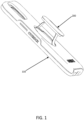
- Figure 1 illustrates a protective case 100 for an electronic device.
- Protective case 100 may also be called a protective cover.
- Protective case 100 is configured with a retractable device grip 200.
- Variations of device grips will be disclosed herein. Different case designs accommodating different grips, holders, and/or stands may involve changing shapes, sizes, dimensions, geometries, quantities, and/or positions of case features described herein to accommodate other grips, holders, or stands.
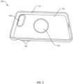
- Figure 2 illustrates a front view of protective case 100 for use with an electronic device, such as a smartphone.
- Protective case 100 includes a body 110 and an inner surface 120.
- Inner surface 120 provides the primary surface(s) for receiving and holding the electronic device in protective case 100.
- Inner surface 120 may contact the electronic device on any one or more of a back surface, on one or more side surfaces, and/or on a portion of a front surface of the electronic device.
- inner surface 120 may also be referred to as or may include a cushion layer, cushioning member, or cushion liner.
- Inner surface 120 can be made of any suitable material such as an elastomer.
- the elastomer may be, but is not limited to, a thermoplastic elastomer or silicone rubber.
- Inner surface 120 may comprise a material that is softer than a material of body 110 for purposes of cushioning, protecting, and/or retaining the electronic device.
- Inner surface 120 may be configured to cushion an installed electronic device from external forces, impacts, sudden acceleration, sudden deceleration, and/or other forces experienced at outer surfaces of protective case 100. Further, the compliant nature of inner surface 120 may allow it to flexibly hold the electronic device to reduce movement, shifting, or rattling of the electronic device within protective case 100. Inner surface 120 may contain cavities, coring, reliefs, ribs, channels, recesses, a grid pattern, protrusions, and/or other similar features for holding the electronic device in place, for protecting the electronic device, and/or for potentially reducing the surface area of contact between inner surface 120 and the installed electronic device.
- inner surface 120 may not cover the entire internal surface of the protective case. In one specific example, inner surface 120 may extend around an internal perimeter of the protective case and may not span the entire back of the protective case or the installed electronic device.
- Protective case 100 also includes a front opening which permits or allows access to at least some portion of the installed electronic device.
- the front opening permits access to an interactive interface of the electronic device such as a touchscreen, a touch screen interface, a resistive touchscreen, a display, and/or a capacitive touchscreen.
- the front opening may contain a lip or edge that removably retains the electronic device in the protective case such that it does not easily or readily come out of the protective case but can still be intentionally removed by a user when desired.
- the front opening may also include a lip, ledge, protrusion, raised edge, rim, elevated rim, elevated protective rim, or other raised feature around at least a portion of the front opening to reduce the chances of a front surface of the installed electronic device from coming into contact with another object or surface, particularly when protective case 100 is laid face down on a flat surface, such as on a table.
- Body 110 of protective case 100 may also be referred to as a structural layer, a frame, a rigid layer, a bottom shell, a shell member, an outer shell, and/or a shell of protective case 100.
- Body 110 extends around some or all of the outer surface of inner surface 120.
- Body 110 will typically be manufactured from a material that is harder, more rigid, stiffer, more puncture resistant, more crush resistant, more chemical resistant, and/or more abrasion resistant than the material of inner surface 120, if any.
- the material of body 110 can be any suitable material such as a thermoplastic polymer or a synthetic polymer.
- the material can include polycarbonate, nylon, or glass filled nylon. Alternately, any other material, or combination of materials, which provide rigidity to protective enclosure 100 can be used.
- Body 110 can be formed using any suitable process, such as an injection molding process.
- the back or sides of body 110 may also include stylistic patterns, images, graphics, and/or one or more color combinations.
- Protective case 100 also includes camera aperture 150 in a back surface of protective case 100.
- Camera aperture 150 which may also be called an opening, provides optical access and/or an optical path to/from a camera and/or a flash of an installed electronic device.
- Camera aperture 150 permits use of the camera and/or flash even though the electronic device is installed in protective case 100 and much of the back of the electronic device is covered by protective case 100.
- Camera aperture 150 may be covered with a clear, mostly clear, transparent, or mostly transparent membrane, lens, or film that protects the camera and/or the flash but also still permits optical access and/or an optical path to/from the camera and/or flash.
- the membrane or film may serve a lensing function and/or provide an optical effect, such as magnification.
- Protective case 100 provides protection for an installed electronic device against external forces by reducing or eliminating transfer of those forces to the installed electronic device, as well as providing a relatively soft contact surface for the installed electronic device.
- the relatively soft contact surface can resist scratching, scraping, marring, and/or rub marks. While providing protection, protective case 100 enables a user to still use the electronic device while it is in protective case 100.
- one of inner surface 120 and body 110 may be comolded (or co-molded) onto the other, comolded with the other, or overmolded onto the other. In another embodiment, they may be molded as separate pieces and adhered together after the molding process. In yet other embodiments, inner surface 120 and body 110 may not be formed, molded, or adhered together but may fit together as an assembly. Inner surface 120 and body 110 may have approximately the same thickness throughout protective enclosure 100 and in other embodiments can vary in thickness. The thickness can vary depending on the manufacturing process and/or the design of protective enclosure 100. In yet other embodiments, inner surface may not be formed from a different material than body 110 and inner surface 120 may simply be the inner surface of the member that makes up body 110.
- protective case or enclosure 100 may provide a one-piece construction that functions like, and provides benefits similar to, a more costly and possibly more complicated two-piece or three-piece assembly.
- the protective case features described herein are not to be limited to a protective case with an inner liner and an outer shell.
- the improvements disclosed herein may be implemented in a case with a single layer (e.g., a hard rigid layer or a soft flexible layer), a case made of a single material (e.g., a polycarbonate, a silicone, etc.), a case made of a single component, a case with more than two layers, a case made of more than two materials, and/or a case made of more than two components.
- the case improvements disclosed herein could be implemented into a clam shell case with two or more pieces, a sliding case with two or more pieces, a hinged case with two or more pieces, etc.
- protective case 100 may be a case that is assembled from a greater number of components or members.
- protective case 100 may be assembled from two members, three members, four members, or more.
- the improvements disclosed herein are not intended to be limited to any particular case or protective case design.
- Protective case 100 also includes one or more button pads 160 on one or more sides of protective case 100.
- button pads 160 may be formed in or from the material that makes up inner surface 120.
- Button pads 160 correspond to respective buttons or control features of an installed electronic device.
- Button pads 160 enable actuation or operation of the respective buttons or control features of the installed electronic device from outside of protective case 100 without necessarily having direct access to the buttons or control features.
- Body 110 and/or inner surface 120 may also include another aperture, hole, or opening for directly accessing a button, switch, port, or control feature of the installed electronic device.
- Button pads and apertures may have many other shapes or configurations.
- a protective case may have more or fewer button pads or apertures than illustrated, or no button pads or apertures at all.
- Protective case 100 also includes grip aperture 140 in the back surface of protective case 100.
- Grip aperture 140 extends from inside of protective case 100 through inner surface 120 and body 110 to provide an aperture or hole that extends all the way through to the back of the case.
- grip aperture 140 facilitates operation and use of a device grip, with a protective case, such as protective case 100.
- the size, shape, quantity, or position, of grip aperture 140 may vary. In some examples, there may be no grip aperture and any of the disclosed grips may be attached directly to an outer surface of protective case 100 and/or directly to a back surface or housing of an electronic device.
- any of the device grips disclosed herein may be implemented as a standalone device or apparatus which is attachable, either permanently or removably, to an electronic device and/or to a case for an electronic device.
- any of the device grips or apparatuses disclosed herein may be integrated into the housing of an electronic device and/or integrated into a case for an electronic device, either permanently or removably.
- the grips and holders disclosed herein are configured or adapted for assisting a user in holding an electronic device and reducing the chances of the user dropping the device.
- the grip is extendable for use and retractable or stowable when not in use. In the extended or use position, the user may extend one or more fingers through or around the grip to assist in holding the device.
- the grip may also act as a stand for one or more viewing orientations for the electronic device when the electronic device is sitting on a surface such as a desk.
- the retracted or stowed position is preferred when the grip is not in use in order to reduce any negative effects of the grip such as getting caught on the edge of a pocket, a purse, or a bag. It is also preferred to reduce the thickness of the grip as much as possible in the retracted or stowed position to better accommodate other functions such as wireless charging, attachment of or to other accessories, and storage.
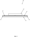
- Figure 3 illustrates a side sectional view of a grip 300 for use with an electronic device and/or with a case for an electronic device.
- Grip 300 includes a base 310 and a cap 320. While illustrated in Figure 3 as a standalone apparatus, grip 300 may be integrated into an electronic device or into a case for an electronic device and base 310 may be part of the electronic device, the housing for the electronic device, or the case for the electronic device.
- Cap 320 is illustrated in the stowed or retracted position. Cap 320 is referred to as a button. As illustrated in subsequent figures, cap 320 may be extended into the extended or use position.
- any of the elements of grip 300 are illustrated in Figure 3 with basic shapes for purposes of explanation of the operation of grip 300. However, it should be understood that any of the elements of grip 300 may have different shapes or sizes while retaining similar functionality. Further, any of the elements disclosed herein may be made from a single component or may be made up of multiple components. Any of the grips disclosed herein may also be referred to as a device grip, a grip apparatus, a gripping apparatus, a holder, a device holder, a device holding apparatus, a case holder, a case handle, a stand, and/or a device stand. Any of the grips or caps disclosed herein may be designed to pivot and/or rotate to permit movement of the device and/or protective case while the grip is being held. Any of the caps disclosed herein may be decorated with any variety of colors, pictures, or graphics. Any of the caps disclosed herein may be removable and replaceable with a different cap for purposes of changing the colors, pictures, or graphics without replacing the entire grip or case.
- Grip 300 also includes two bendable strips 330 which are attached to cap 320.
- Bendable strips 330 may be formed from any relatively thin flexible, bendable, and/or resilient material that is substantially flat and may return to its substantially flat state after being bent.
- Bendable strips 330 may be formed from a plastic film, from a plastic strip, from a thin metallic strip, or from another material that is bendable, semi-rigid, rigid, and/or returns to its original shape.
- bendable strips 330 may have some cross-sectional curvature, similar to a metal measuring tape, which further causes them to tend to return to a straight or flat position.
- Bendable strips 330 may also be referred to as strips, straps, bendable straps, arms, bendable arms, or extension arms.
- bendable strips 330 appear as lines because they are being viewed from the side. Bendable strips 330 are each positioned in a slot 312 of base 310 and extend through an opening or aperture of base 310 to be attached to cap 320. Slots 312 may also be referred to as a cavity or a channel. In some examples, slots 312 may not be fully enclosed and may be formed as a channel in a surface with extensions or tabs which extend over the channel only partially to retain bendable strips 330 in the channel.
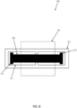
- Figure 4 illustrates a top sectional view of grip 300 of Figure 3 .
- the section view of Figure 4 cuts through base 310.
- Cap 320 is illustrated in dashed lines for reference only.
- Figure 4 illustrates bendable strips 330 in slots 312.
- the ends of bendable strips 330 extend up (out of the page) through openings or apertures to attach to cap 320.
- Each of bendable strips 330 includes one or more stop features 332 which corresponds to a shape of the end of the corresponding slot 312. As explained further in subsequent figures, stop features 332 prevent bendable strips 330 from sliding or extending all the way out of or exiting slots 312.
- Figure 5 illustrates a side sectional view of grip 300, similar to Figure 3 , but in the extended or use position.
- Cap 320 has been pulled or extended upward such that a user can place one or more fingers between cap 320 and base 310. Alternately, cap 320 may be used as a stand.
- bendable strips 330 are partially pulled out of slots 312. They can be pulled until stop features 332 reach the corresponding shoulder or stop feature of slots 312 (see Figure 4 ) and prevent the bendable strips 330 from extending or exiting slots 312 any further. Since bendable strips 330 are semi-rigid and are extending from opposite directions they tend to press against each other and hold cap 320 up in the extended position. While the grip illustrated in Figure 1 has some features that are different than grip 300, Figure 1 generally illustrates the use position of any of the grips disclosed herein relative to a protective case.
- bendable strips 330 are viewed from their edges such that they appear very thin. When viewed from another direction, such as from the left of the page or the right of the page, each bendable strip will have a more substantial width that is not visible in Figure 5 .
- the width of any of the bendable strips, straps, or arms disclosed herein may also be reduced or variable, such as having an hourglass shape, to better accommodate a user's fingers in more than one direction. In other words, the width of any of the bendable strips disclosed herein may not be uniform and may include contours where a user's fingers are expected such that the user does not have to spread his fingers as far apart to hold the grip from a variety of directions or orientations.
- Figure 6 illustrates a top sectional view of grip 300 of Figure 5 in the extended position.
- the section view of Figure 6 cuts through base 310.
- Cap 320 is illustrated in dashed lines for reference only.
- Figure 6 illustrates bendable strips 330 extended out of slots 312. The extended ends of bendable strips 330 extend up (out of the page) to attach to cap 320, which is extended to or toward the use position.
- the stop features 332 are at or near the stops of slots 312 preventing bendable strips 330 from sliding or extending further out of slots 312. In this way, cap 320 remains attached to base 310 and can only be extended out a specified distance. After use, cap 320 can be pressed or pushed down and returned to the retracted or stowed position illustrated in Figures 3 and 4 .
- Figure 7 illustrates a side sectional view of a grip 700 for use with an electronic device and/or with a case for an electronic device.
- Grip 700 may include any of the features, functions, elements, or characteristics of grip 300.
- Grip 700 includes a base 710 and a cap 720.
- Base 710 may include any of the features, functions, elements, or characteristics of base 310.
- Cap 720 may include any of the features, functions, elements, or characteristics of cap 320. While illustrated in Figure 7 as a standalone apparatus, grip 700 may be integrated into an electronic device or a case for an electronic device and base 710 may be part of the electronic device, the housing for the electronic device, or the case for the electronic device. Cap 720 is illustrated in the stowed or retracted position.
- Cap 720 is referred to as a button. As illustrated in subsequent figures, cap 720 may be extended into the extended or use position.
- the elements of grip 700 are illustrated in Figure 7 with basic shapes for purposes of explanation of the operation of grip 700. However, it should be understood that any of the elements of grip 700 may have different shapes or sizes while retaining same or similar functionality. Further, any of the elements disclosed herein may be made from a single component or may be made up of multiple components.
- Grip 700 also includes a bendable strip 730 which is attached to cap 720.
- Bendable strip 730 may include any of the features, functions, elements, or characteristics of bendable strips 330.
- Bendable strip 730 may be formed from any relatively thin flexible and/or bendable material that is substantially flat and tends to return to its substantially flat state after being bent.
- Bendable strip 730 may be formed from a plastic film, a plastic strip, from a thin metallic strip, or from another material.
- bendable strip 730 may have some cross-sectional curvature, similar to a metal measuring tape, which further causes it to have a tendency to return to a straight or flat position.
- Bendable strip 730 may also be referred to as a strip, strap, arm, bendable strap, bendable arm, or extension arm.
- bendable strip 730 appears as a line because it is being viewed from the thin side. Bendable strip 730 is positioned in a slot 712, which may also be referred to as a channel, of base 710 and extends through one or more openings or apertures of base 710 to be attached to cap 720.
- bendable strip 730 is a single strip that is attached to cap 720 and extends from cap 720 in both directions into base 710.
- bendable strip 730 may be attached to cap 720 near a center point of bendable strip 730.
- Cap 720 may retain bendable strip 730 using a pin or bar.
- Slot(s) 712 may also be referred to as a cavity or a channel. In some examples, slot(s) 712 may not be fully enclosed and may be formed as a channel in a surface with extensions or tabs which extend over the channel only partially to retain bendable strip 730 in the channel.
- Figure 8 illustrates a top sectional view of grip 700 of Figure 7 .
- the section view cuts through base 710.
- Cap 720 is illustrated in dashed lines for reference only.
- Figure 8 illustrates bendable strip 730 in slot(s) 712. Bendable strip 730 extends up (out of the page) through openings or apertures to attach to cap 720.
- Bendable strip 730 includes stop features 732 which correspond to a shape of slot 712. As explained further in subsequent figures, stop features 732 prevent each end of bendable strip 730 from sliding or extending all the way out of slot 712.
- Figure 9 illustrates a side sectional view of grip 700, similar to Figure 7 , but in the extended or use position.
- Cap 720 has been pulled or extended upward such that a user can place one or more fingers between cap 720 and base 710, or to use cap 720 as a stand.
- bendable strip 730 is partially pulled out of slot 712 from two directions. It is pulled until stop features 732 reach the corresponding shoulders of slot 712 (see Figure 8 ) and prevent the bendable strip 730 from extending or exiting slot 712 any further.
- Bendable strip 730 is flexible enough to permit some side to side movement but rigid enough to hold cap 720 away from base 710 and rigid enough for extended cap 720 to act as a stand when the electronic device is on a table, desk, or other substantially horizontal surface. While the grip illustrated in Figure 1 has some features that are different than grip 700, Figure 1 generally illustrates the use position of any of the grips disclosed herein relative to a protective case.
- Figure 10 illustrates a top sectional view of grip 700 of Figure 9 in the extended position.
- the section view cuts through base 710.
- Cap 720 would exist above the illustrated section, but is illustrated in dashed lines for reference purposes.
- Figure 10 illustrates bendable strip 730 extended out of slot(s) 712. Two parallel portions of bendable strip 730 extend up to cap 720. Bendable strip 730 extends up (out of the page) to attach to extended cap 720.
- the stop features 732 are at or near the stops of slot 712 preventing bendable strips 730 from sliding or extending further out of slot(s) 712. In this way, cap 720 remains attached to base 710 and can only be extended out a specified distance. After use, cap 720 can be pressed or pushed down and returned to the retracted or stowed position illustrated in Figures 7 and 8 .
- Figure 11 illustrates a side sectional view of a grip 1100 for use with an electronic device and/or with a case for an electronic device.
- Grip 1100 may include any of the features, functions, elements, or characteristics of grips 300 or 700.
- Grip 1100 includes a base 1110 and a cap 1120.
- Base 1110 may include any of the features, functions, elements, or characteristics of base 310 or 710.
- Cap 1120 may include any of the features, functions, elements, or characteristics of cap 320 or 720. While illustrated in Figure 11 as a standalone apparatus, grip 1100 may be integrated into an electronic device or a case for an electronic device. Base 1110 may also be part of the electronic device, the housing for the electronic device, or the case for the electronic device.
- Cap 1120 is illustrated in the stowed or retracted position. Cap 1120 is referred to as a button. As illustrated in subsequent figures, cap 1120 may be extended into the extended or use position.
- the elements of grip 1100 are illustrated in Figure 11 with basic shapes for purposes of explanation of the operation of grip 1100. However, it should be understood that any of the elements of grip 1100 may have different shapes or sizes while retaining similar functionality. Further, any of the elements disclosed herein may be made from a single component or may be made up of multiple components.
- Grip 1100 also includes bendable strips 1130 which are attached near ends or edges of cap 1120.
- Bendable strips 1130 may include any of the features, functions, elements, or characteristics of bendable strips 330 or 730.
- Bendable strip 1130 may be formed from any relatively thin flexible, resilient, and/or bendable material that is substantially flat and tends to return to its substantially flat state after being bent.
- Bendable strip 1130 may be formed from plastic, a plastic film, from a thin metallic strip, or from another material.
- bendable strips 1130 may have some cross-sectional curvature, similar to a metal measuring tape, which further causes them to tend to return to a straight or flat position.
- Bendable strips 1130 may also be referred to as a strip, strap, bendable strap, arm, bendable arm, or extension arm. In Figure 11 , bendable strips 1130 appears as lines because they are being viewed from the side. Bendable strips 1130 are positioned in a slot 1112 of base 1110 and extend through openings or apertures of base 1110 to be attached to cap 1120. Unlike grips 300 and 700, bendable strips 1130 extend from opposite or opposing sides or edges of base 1110 and attach to opposing sides or edges of cap 1120. Slot 1112 may also be referred to as a cavity or a channel. In some examples, slot 1112 may not be fully enclosed and may be formed as a channel in a surface with extensions which extend over the channel only partially to retain bendable strips 1130 in the channel.
- Figure 12 illustrates a top sectional view of grip 1100 of Figure 11 .
- the section view cuts through base 1110.
- Cap 1120 is illustrated in dashed lines for reference only.
- Figure 12 illustrates bendable strips 1130 in slot 1112. Bendable strips 1130 extend up (out of the page) through openings or apertures at opposite ends of base 1110 to attach to cap 1120. Bendable strips 1130 includes stop features 1132 which correspond to a shape at ends of slot 1112. As explained further in subsequent figures, stop features 1132 prevent each end of bendable strips 1130 from sliding or extending all the way out of or exiting slot 1112.
- Figure 13 illustrates a side sectional view of grip 1100, similar to Figure 11 , but in the extended or use position.
- Cap 1120 has been pulled or extended upward such that a user can place one or more of fingers between cap 1120 and base 1110 between bendable strips 1130.
- Cap 1120 may also act as a stand or a holding point for a wall mount, a desk mount, and/or a car mount.
- bendable strips 1130 are partially pulled out of slot 1112 from two opposite directions. Bendable strips 1130 are pulled until stop features 1132 reach the corresponding shoulders of slot 1112 (see Figure 12 ) which prevent the bendable strips 1130 from further extending out of slot 1112 any further and/or exiting slot 1112.
- Figure 14 illustrates a top sectional view of grip 1100 of Figure 13 in the extended position.
- the sectional view cuts through base 1110.
- Cap 1120 is illustrated in dashed lines for reference only.
- Figure 14 illustrates bendable strips 1130 extended out of slot 1112.
- Each bendable strip 1130 extends up to cap 1120. Bendable strips 1130 extend up (out of the page) to attach to opposing sides or edges of extended cap 1120.
- the stop features 1132 are at or near the stops of slot 1112 preventing bendable strips 1130 from sliding or extending further out of slot 1112. In this way, cap 1120 remains attached to base 1110 and can only be extended out a specified distance.
- the fact that bendable strips 1130 extend out from opposite directions and are bent in opposite directions tends to keep cap 1120 centered in an upright position.
- cap 1120 can be pressed or pushed down and returned to the retracted or stowed position illustrated in Figures 11 and 12 .
- Figure 15 illustrates a grip 1500 attached to the back of a protective case 110.
- Grip 1500 may include any of the features, functions, elements, or characteristics of grips 300, 700, and/or 1100.
- grip 1500 is in the extended or use position and can be pressed down when not in use.
- Grip 1500 may or may not be removable from protective case 110.
- One or more of a user's fingers may be extended through the opening between bendable strips 1530 for improving the user's grip on the assembly and/or reducing the chances of dropping it.
- another accessory such as a wireless charger, may alternately be placed between bendable strips 1530 and under the cap. This configuration may enable the wireless charger to be closer to the back of the electronic device than it would be if grip 1500 was in the stowed position and the wireless charger was on top of the stowed grip.
- Figure 16 illustrates grip 1500 without protective case 110.
- Cap 1520 and bendable strips 1530 are similar to cap 1120 and bendable strips 1130, respectively, of grip 1100.
- grip 1500 does not necessarily contain the same configuration of base and slots as other grips disclosed herein.
- Bendable strips 1530 are each attached to a frame 1510 which holds them in position.
- Frame 1510 and bendable strips 1530 may be formed, molded, punched, or die-cut from a single piece of material rather than being separate components. In another example, they may contain a stack of two or more materials to accomplish a variety of characteristics including strength, rigidity, flexibility, durability, stiffness, resilience, and/or smoothness. In other examples, they many be made of different materials.
- the grip structure illustrated in Figure 16 may provide a thin structure. Height reduction allows grip 1500 to protrude less from the back of an electronic device or from a case when grip 1500 is stowed and not in use. Grip 1500 may be somewhat flush, substantially flush, or completely flush with a back surface of the protective case. This minimizes the chance of grip 1500 catching on pockets, edges of bags, etc. when not in use and makes the assembly generally easier to store. It also permits a wireless charger to be closer to the back surface of the installed electronic device without removing grip 1500 and/or the protective case thereby improving wireless charging performance. Other types of grips may have to be removed for wireless charging.
- Figure 17 illustrates grip 1500 of Figure 16 with a top portion of cap 1520 removed.
- the ends of bendable strips 1530 inside cap 1520 are visible, including stop features 1532 which prohibit bendable strips 1530 from being pulled out of or exiting cap 1520 entirely.
- stop features 1532 which prohibit bendable strips 1530 from being pulled out of or exiting cap 1520 entirely.
- the extension of cap 1520 from frame 1510 is limited to a particular length or distance.
- bendable strips 1530 extend into cap 1520 until cap 1520 is against, or substantially close to, frame 1510.
- Frame 1500 may be attached to an internal surface of a protective case such that grip 1500 extends through an aperture of the protective case and/or frame 1500 may be attached to another element which is attached to an internal surface of a protective case such that grip 1500 extends through an aperture of the protective case.
- Figure 18 illustrates a side sectional view of grip 1500.
- Cap 1520 is illustrated in the stowed or retracted position.
- Cap 1520 is referred to as a button.
- cap 1520 may be extended into the extended or use position.
- the elements of grip 1500 are illustrated in Figure 18 with basic shapes for purposes of explanation of the operation of grip 1500. However, it should be understood that any of the elements of grip 1500 may have different shapes or sizes while retaining similar functionality. Further, any of the elements disclosed herein may be made from a single component or may be made up of multiple components.
- Bendable strips 1530 are attached near ends or edges of base 1510. Bendable strips 1530 may include any of the features, functions, elements, or characteristics of bendable strips 330, 730, or 1130. Bendable strips 1530 may be formed from any relatively thin flexible and/or bendable material that is substantially flat and tends to return to its substantially flat state after being bent. Bendable strips 1530 may be formed from a plastic film, from plastic, from a thin metallic strip, or from another material. In some examples, bendable strips 1530 may have some cross-sectional curvature, similar to a metal measuring tape, which further causes them to have a tendency to return to a straight or flat position. Bendable strips 1530 may also be referred to as a strip, strap, bendable strap, arm, bendable arm, or extension arm.
- bendable strips 1530 appear as lines because they are being viewed from the side. Bendable strips 1530 are positioned in a slot 1512 of cap 1520 and slide in and out of cap 1520 as illustrated in Figures 15-17 . Similar to grip 1100, bendable strips 1530 extend from opposite sides or outer edges of the device. However, in grip 1500 bendable strips 1530 have a fixed attachment to base 1510 and slide in and out of one or more slots 1512 in cap 1520 to provide the travel or movement between the extended position and the stowed position.
- Slot 1512 may also be referred to as a cavity or a channel. In some examples, slot 1512 may not be fully enclosed and may be formed as a channel in a surface with extensions which extend over the channel only partially to retain bendable strips 1530 in the channel. In some examples, methods other than those illustrated in Figures 4 , 6 , 8 , 10 , 12 , and 14 may be used to limit the travel or distance of movement of the bendable strip(s).
- the bendable strip(s) may include a slot and the cap or base may include one or more posts that extend through the slot such that the post(s) travel through the range of the slot of the bendable strip when the bendable strip is moved.
- Figure 19 illustrates a grip 1900 having some similarities to grip 1500.
- Cap 1920 and bendable strips 1930 are similar to cap 1520 and bendable strips 1530, respectively, of grip 1500. Similar to grip 1500, bendable strips 1930 have a fixed attachment to a lower frame 1910 and slide in and out of cap 1920 to achieve the extension and retraction movements.
- Frame 1910 and bendable strips 1930 may be formed, punched, or die-cut from a single piece of material. In another example, they may comprise a stack of two or more materials to accomplish a variety of characteristics including strength, rigidity, flexibility, durability, stiffness, resilience, and/or smoothness.
- Frame 1910 may be temporarily or permanently adhered to a case or to an electronic device. Alternately, frame 1910 may be otherwise adhered to or captured by a case or by an electronic device.
- Figure 20 illustrates a side section view of grip 1900 in the stowed position.
- the structure and movement of grip 1900 has similarities to grip 1500 as illustrated in Figure 18 in that the bendable strips slide in and out of the cap from opposite directions.
- the two bendable strips 1930 are overlapped in cap 1920 such that one slides above the other. They may have length such that some overlap still exists when they are in the extended position in order to maintain the orientation between them. This configuration allows the overall length or size of grip 1900 to be reduced.
- grip 1900 may optionally include a divider 1940 which is a thin piece of film or other material that separates the bendable strips 1930 so they are not sliding directly against each other.
- the two bendable strips 1930 may be a single strip that retracts into a collapsed "S" shape inside cap 1920.
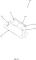
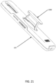
- Figure 21 illustrates grip 1900 in protective case 100 and extending out of an opening or aperture in a back surface of protective case 100.
- grip 1900 When collapsed into the stowed position, grip 1900 may be flush, substantially flush, or nearly flush, and/or recessed relative to the back surface of protective case 100.
- this geometry may also provide wireless charging performance for the installed electronic which is as good, or nearly as good, as the charging performance would be if the grip is not present because the wireless charger is able to be placed as close to the device as it could be were the grip not present. This provides a significant advantage over other solutions in which a grip must be removed for wireless charging.
- any of the grips, grip apparatuses, or grip components disclosed herein may be manufactured from or include materials which preferred or increased magnetic permeability characteristics for improving the performance of a wireless charger by improving the magnet inductive coupling between the wireless charger and the electronic device which is inside the case on an opposite side of the grip.
- Grip 1900 may be permanently or temporarily attached to protective case 100 from one side, both sides, or either side. Grip 1900 may be attached with an adhesive, magnets, a friction fit, an interference fit, a tab, a groove, a clip, a mechanical fastener, co-molding, a hook-and-loop fastener, a snap, and/or a rotational attachment mechanism.
- any of the grips disclosed herein may be sized to fit within a particular feature or dimension of the electronic device and/or the protective case.
- any of the grip assemblies disclosed herein may fit within the circular shape of the APPLE MAGSAFE magnet array. In this way, the grip has minimal impact on the performance or use of the MAGSAFE interface.
- flush and/or low profile grips disclosed herein may also result in the grip having little or no effect on the magnet attraction features of such an interface.
- the flush and/or low profile grips disclosed herein may also enable the device and/or case to be attached to a magnetic desk or car mount without removing the grip.
- any of the grips or cases disclosed herein may also include one or more magnets for establishing a magnetic interface with other devices or for enhancing an existing magnetic interface.
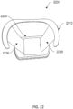
- Figure 22 illustrates a bottom view of a grip 2200 in the extended position.
- Grip 2200 has similarities to and may include any of the elements, features, or characteristics of the other grip devices disclosed herein.
- Cap 2220 is similar to cap 1520 and other caps disclosed herein.
- Frame 2210 which may also be referred to as a base, is similar to other frames disclosed herein, such as frame 1910, but does not have a complete or closed circumference. In other words, frame 2210 has a gap or opening in its perimeter edge. As discussed with respect to subsequent figures, the opening in frame 2210 facilitates installation into another object.
- Bendable strips 2230 are similar to bendable strips 1530 of grip 1500.
- Bendable strips 2230 have a fixed attachment to frame 2210 and/or are formed from a same piece of material as frame 2210, but may be formed from a different material in some examples. Bendable strips 2230 slide in and out of cap 2220 to achieve the extension and retraction movements as discussed in prior examples.
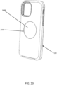
- Figure 23 illustrates protective case 100 with an opening 2688 for receiving any of the grips, grip apparatuses, or holders disclosed herein. Opening 2688 may also be referred to as a cavity. Opening 2688 may extend all the way through the back wall of protective case 100 or may be a recess or cavity with a bottom where it does not extend all the way through the back wall of protective case 100. In the example of Figure 23 , opening 2688 is circular and has a specified diameter. In other examples, opening 2688 may have a different shape. Opening 2688 includes a lip 2689 around some or all of the diameter of opening 2688. The cavity of opening 2688 extends back under the edge of lip 2689 such that such that a grip or other object can expand into the cavity under the lip and be attached to protective case 100.
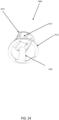
- Figure 24 illustrates a bottom view of a grip 2600 in the extended position.
- Grip 2600 has similarities to and may include any of the elements, features, or characteristics of the other grip devices disclosed herein.
- Cap 2620 is similar to cap 1520, cap 2220, and/or other caps disclosed herein.
- Frame 2610 is similar to other frames disclosed herein, such as frame 1910, frame 2210, and/or others.
- Grip 2600 also includes bendable strips 2631 and 2632 which may be similar to bendable strips 1530 of grip 1500 and/or bendable strips 2230 of grip 2200. Bendable strips 2631 and 2632 have a fixed attachment to frame 2610 and/or are formed from a same piece of material as frame 2610. Bendable strips 2631 and 2632 may also be formed from a different material than frame 2610.
- Bendable strips 2631 and 2632 slide in and out of cap 2620 to achieve the extension and retraction movements similar to those discussed in prior examples. Unlike prior examples, bendable strips 2631 and 2632 are configured to be side-by-side with each other or side adjacent to each other in cap 2620 rather than sliding one over the other as illustrated in Figure 22 . Grip 2600 may include fewer or more bendable strips.
- Figure 25 illustrates an alternate view of grip 2600 of Figure 25 .
- Frame 2610 which may also be referred to as a base, includes a gap 2691 in the circumference. Gap 2691 may also be referred to as a break or a discontinuity.
- frame 2610 is in a relaxed state and has a specified diameter. When an external force is temporarily applied to framed 2610 it can be squeezed or compressed to reduce or close gap 2691 and temporarily reduce the dimension or diameter of frame 2610 so it can fit into a smaller opening, such as opening 2688 of protective case 100 in Figure 23 .
- frame 2610 When the external force is removed, frame 2610 will relax or return to the original diameter (illustrated in Figure 25 ) and it will expand under lip 2689 thereby temporarily attaching, affixing, or retaining grip 2600 to protective case 100 until it is intentionally removed by applying a similar force again.
- Figure 26 illustrates grip 2600 of Figures 24 and 25 in the collapsed or stowed position.
- Cap 2620 may have a variety of shapes to facilitate use as a grip. Cap 2620 may be round, oval, square, or rectangular. Further, cap 2620 may have a shape or features to fit into opening 2688 when in the stowed position. Some or all of cap 2620 may have an arced or circular ship to match at least a portion of opening 2688. In the example of Figure 26 , cap 2620 may also have one or more sections which leave one or more portions of opening 2688 accessible even when it is in the stowed position.
- cap 2620 may form an hourglass shape to provide more fingertip room while still maintaining the overall width of cap 2620. Other shapes are possible.
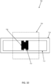
- Figure 27 illustrates a bottom view of device grip 2600 of Figure 26 in the stowed position.
- Bendable strips 2631 and 2632 are configured to be side-by-side with each other or side adjacent to each other, which may make it possible to make device grip 2600 thinner and/or flatter.
- Device grip 2600 may also include stop features such as stop features 2633 and 2634 which may limit a distance bendable strips 2631 and 2632 can be extended out of frame 2610 toward the extended position illustrated in Figure 26 .
- any of the bendable strips disclosed herein may be comprised of two or more layers of materials having different characteristics.
- a first material for the bendable strips may be selected based on desired rigidity, stiffness, bendability, resilience, durability, and/or strength characteristics.
- a stiffer material may tend to keep the device grip in one or more of the extended or stowed positions until an external force is applied to change the position.
- the first material may be overmolded, covered, or coated with a second material that provides different characteristics on one or more surfaces of the bendable strips.
- the second material may be chosen to slide easily against other parts, to prevent binding, for user feel, for comfort, for softness, for scuff or scratch resistance, and/or for preferred color characteristics.
- the second material may cover or extend over the first material on one, two, or all sides of the bendable strip.
- Figure 28 illustrates device grip 2600 of Figure 27 attached to protective case 100 and in the stowed position.
- cap 2620 is made from a clear or transparent material such that bendable strips 2631 and 2632 are visible inside, below, and/or through cap 2620.
- Device grip 2600 may attach to protective case 100 in a manner similar to that described with respect to Figures 24 and 25 .
- Figure 29 illustrates device grip 2600 attached to protective case 100 and in the extended position.
- Figure 29 illustrates an alternate view of the grip of Figure 24 attached to a protective case and in the extended position.
- Figure 30 illustrates the protective case and grip of Figure 29 in the stowed position.
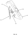
- Figure 31 illustrates the grip and protective case of Figures 29 and 30 in a stand orientation for use on a table, desk, or other substantially horizontal surface.
- Grip 2600 may be rotated to a preferred position depending on which orientation is preferred for protective case 100.
- grip 2600 may be partially extended on one or more sides, as illustrated in Figure 31 , in order to achieve a different stand angle.
- grip 2600 may also be used to attach the assembly to another object such as a wall mount or a car mount.
- any of the grips or holders disclosed herein may be substantially flush, or even recessed, when in the stowed position such that another feature is helpful when extending the grip.
- Any of the grips or holders disclosed herein may include a small cutout, recess, or edge for lifting the grip with a fingernail or other small object, such as a coin.
- the grip may rock or pivot when in the stowed position and pressure is applied to an edge in order to temporarily raise and provide access at an opposing edge for extending the grip.
- Various components described herein may be manufactured, provided, or sold in the form of a system or a kit.
- the system or kit may include any combination of: a protective case or cover having any combination of the features described herein and a compatible device grip, or multiple compatible device grips or components.
- the system or kit need not include every component or feature described herein.
Landscapes
- Casings For Electric Apparatus (AREA)
- Purses, Travelling Bags, Baskets, Or Suitcases (AREA)
Claims (14)
- Griffsystem, das zur Unterstützung des Haltens einer elektronischen Vorrichtung ausgestaltet ist, wobei das Griffsystem Folgendes umfasst:ein Schutzgehäuse (100), das eine schützende Schale (110) zur Aufnahme der elektronischen Vorrichtung und zum Abdecken mindestens eines Abschnitts eines Gehäuses der elektronischen Vorrichtung umfasst, wobei das Schutzgehäuse (100) eine Rückfläche mit einer Aussparung aufweist, undeine Griffvorrichtung (300), die an der Rückseite des Schutzgehäuses (100) abnehmbar anbringbar ist, wobei die Griffvorrichtung (300) Folgendes umfasst:eine Basis (310), die dazu ausgestaltet ist, abnehmbar in die Aussparung in der Rückseite des Schutzgehäuses (100) eingeführt zu werden, um die Griffvorrichtung (300) abnehmbar an dem Schutzgehäuse (100) anzubringen,zwei flexible Bandstreifen (330), die jeweils aus einem biegsamen Material gebildet sind, wobei jeder flexible Bandstreifen (330) ein erstes Ende und ein zweites Ende aufweist,dadurch gekennzeichnet, dass das erste Ende jedes flexiblen Bandstreifens an der Basis (310) angebracht ist,wobei eine Kappe (320), bei der es sich um einen Knopf handelt, ausgestaltet ist dazu beizutragen, dass ein Benutzer das Schutzgehäuse (100) halten kann, wobei die Kappe (320) in einer verstauten Position in der Nähe einer oberen Fläche der Basis angeordnet ist, wobei die Kappe (320) von der oberen Fläche der Basis (310) weg von dem Schutzgehäuse (100) ausziehbar ist, wenn die Kappe (320) nach außen gezogen wird, um die Kappe (320) in eine ausgezogene Position auszuziehen, wobei jeder flexible Bandstreifen (330) dazu ausgestaltet ist, mindestens teilweise in einem Schlitz (312) in der Kappe (320) zu gleiten, wobei jeder flexible Bandstreifen (330) in den Schlitz (312) gleitet, wenn die Griffvorrichtung (300) in die verstaute Position überführt wird, und aus dem Schlitz (312) nach außen gleitet, wenn die Griffvorrichtung (300) in die ausgefahrene Position überführt wird, und wobei ein Anschlag (332) in der Nähe des zweiten Endes jedes flexiblen Bandstreifens (330) eine maximale Ausziehlänge festlegt und verhindert, dass der jeweilige flexible Bandstreifen (330) vollständig aus dem Schlitz (312) der Kappe (320) austritt.
- Griffsystem nach Anspruch 1, wobei die Griffvorrichtung (300) bezüglich des Schutzgehäuses (100) drehbar ist, wenn sie an der schützenden Schale (100) angebracht ist.
- Griffsystem nach einem der Ansprüche 1 oder 2, wobei jeder flexible Bandstreifen (330) im Wesentlichen planar ist, wenn sich die Griffvorrichtung (300) in der verstauten Position befindet, und wobei sich jeder flexible Bandstreifen (330) biegen muss, um in den Schlitz (312) in der Kappe (320) und aus diesem heraus zu gleiten, wenn die Griffvorrichtung (300) zwischen der verstauten Position und der ausgefahrenen Position überführt wird.
- Griffsystem nach einem der vorangehenden Ansprüche, wobei der Schlitz (312) in der Kappe (320) zwei Schlitze ist und jeder der flexiblen Bandstreifen (330) in einem separaten der beiden Schlitze in der Kappe (320) gleitet.
- Griffsystem nach einem der vorhergehenden Ansprüche, wobei der Schlitz (312) einen Teiler (1940) aufweist, der mindestens einen Abschnitt des Schlitzes (312) in zwei Bereiche teilt, wobei jeder der flexiblen Bandstreifen (330) auf einer dem anderen flexiblen Bandstreifen (330) gegenliegenden Seite des Teilers (1940) in dem Schlitz (312) gleitet.
- Griffsystem nach einem der vorhergehenden Ansprüche, wobei die beiden flexiblen Bandstreifen (330, 1930) in der Kappe (320, 1920) so überlappt sind, dass einer über dem anderen gleitet.
- Griffsystem nach Anspruch 1, wobei die Griffvorrichtung (300) einen Teiler (1940) aufweist, der ein dünnes Stück Folie oder ein anderes Material ist, das die flexiblen Bandstreifen (330) trennt, so dass sie nicht direkt aneinandergleiten.
- Griffsystem nach einem der vorhergehenden Ansprüche, wobei:die Aussparung in der Rückseite des Schutzgehäuses (100) eine kreisförmige Öffnung (140) und einen Abschnitt aufweist, der sich von der Öffnung (140) unter einer Lippe des Schutzgehäuses (100) erstreckt, unddie Basis (310) der Griffvorrichtung (300) eine kreisförmige Form mit einem Durchmesser hat, der größer als der Durchmesser der Öffnung (140) des Schutzgehäuses (100) ist.
- Griffsystem nach Anspruch 8, wobei die Basis (310) so ausgestaltet ist, dass sie sich bei Beaufschlagung mit einer externen Kraft vorübergehend deformiert, so dass die Basis (310) vorübergehend durch den Durchmesser der Öffnung (140) und in die Aussparung des Schutzgehäuses (100) passt.
- Griffsystem nach Anspruch 9, wobei die Basis (310) so ausgestaltet ist, dass sie sich auf den ursprünglichen Durchmesser der Basis (310) entspannt, wenn die äußere Kraft entfernt wird, so dass sich die Basis (310) unter die Lippe erstreckt, wodurch die Griffvorrichtung (300) an dem Schutzgehäuse (100) angebracht wird.
- Griffsystem nach einem der Ansprüche 9 oder 10, wobei die kreisförmige Form der Basis (310) eine Lücke in der kreisförmigen Form der Basis (310) aufweist, wobei die Lücke dazu ausgestaltet ist, die Deformierung bei der Beaufschlagung mit der äußeren Kraft zu erleichtern.
- Griffsystem nach einem der vorhergehenden Ansprüche, wobei die Kappe (320) der Griffvorrichtung (300) im Wesentlichen mit der Rückfläche des Schutzgehäuses (100) bündig ist, wenn sich die Griffvorrichtung (300) in der verstauten Position befindet.
- Griffsystem nach einem der vorhergehenden Ansprüche, wobei die Kappe (320) ferner dazu ausgestaltet ist, als Ständer für das Schutzgehäuse (100) zu dienen, wenn sich die Griffvorrichtung (300) in der ausgefahrenen Position oder in einer teilweise ausgefahrenen Position befindet.
- Griffsystem nach einem der vorhergehenden Ansprüche, wobei die Kappe (320) und die flexiblen Bandstreifen (330) dazu ausgestaltet sind, einen oder mehrere Finger eines Benutzers zum Halten der Griffvorrichtung (300) und des Schutzgehäuses (100) aufzunehmen, wenn sich die Griffvorrichtung (300) in der ausgefahrenen Position befindet.
Applications Claiming Priority (5)
| Application Number | Priority Date | Filing Date | Title |
|---|---|---|---|
| US202163167198P | 2021-03-29 | 2021-03-29 | |
| US202163190869P | 2021-05-20 | 2021-05-20 | |
| US202163234551P | 2021-08-18 | 2021-08-18 | |
| US202163272480P | 2021-10-27 | 2021-10-27 | |
| PCT/US2022/021459 WO2022212136A1 (en) | 2021-03-29 | 2022-03-23 | Collapsible and extendable device grip |
Publications (2)
| Publication Number | Publication Date |
|---|---|
| EP4312656A1 EP4312656A1 (de) | 2024-02-07 |
| EP4312656B1 true EP4312656B1 (de) | 2025-05-07 |
Family
ID=83363985
Family Applications (1)
| Application Number | Title | Priority Date | Filing Date |
|---|---|---|---|
| EP22719397.6A Active EP4312656B1 (de) | 2021-03-29 | 2022-03-23 | Faltbarer und ausziehbarer vorrichtungsgriff |
Country Status (4)
| Country | Link |
|---|---|
| US (2) | US12433391B2 (de) |
| EP (1) | EP4312656B1 (de) |
| CA (1) | CA3211100A1 (de) |
| WO (1) | WO2022212136A1 (de) |
Families Citing this family (15)
| Publication number | Priority date | Publication date | Assignee | Title |
|---|---|---|---|---|
| US20250050492A1 (en) * | 2010-10-26 | 2025-02-13 | Michael Shayne KARMATZ | Compacting grip for handheld devices |
| US12433391B2 (en) * | 2021-03-29 | 2025-10-07 | Otter Products, Llc | Collapsible and extendable device grip |
| TWI766717B (zh) * | 2021-06-04 | 2022-06-01 | 愛進化科技股份有限公司 | 用於手持裝置之配件 |
| TWD218151S (zh) | 2021-06-04 | 2022-04-11 | 愛進化科技股份有限公司 | 用於手持裝置之配件 |
| TWI805102B (zh) | 2021-11-30 | 2023-06-11 | 愛進化科技股份有限公司 | 用於一手持裝置之立架、包含該立架之保護殼及用以支撐一手持裝置之手段 |
| TWI786967B (zh) | 2021-11-30 | 2022-12-11 | 愛進化科技股份有限公司 | 用於一手持裝置之立架及包含該立架之保護殼 |
| USD1091523S1 (en) * | 2022-07-29 | 2025-09-02 | Changki YEO | Combined portable device and card holder |
| TWI824762B (zh) * | 2022-10-07 | 2023-12-01 | 愛進化科技股份有限公司 | 手持裝置之配件 |
| US12575654B2 (en) | 2022-11-09 | 2026-03-17 | Otter Products, Llc | Protective case with grip and stand |
| US20240219970A1 (en) * | 2023-01-04 | 2024-07-04 | ohSnap, Inc. | Configurations for Grips for Portable Handheld Devices |
| KR102532654B1 (ko) * | 2023-03-31 | 2023-05-15 | 여창기 | 휴대단말기용 홀더 |
| CN116608398A (zh) * | 2023-04-27 | 2023-08-18 | 深圳市嘉音美电子有限公司 | 一种多功能智能设备辅助握持装置 |
| USD1099883S1 (en) * | 2023-08-23 | 2025-10-28 | GuangDong QianDu Technology Co., LTD | Mobile phone holder |
| US20260025453A1 (en) * | 2024-07-19 | 2026-01-22 | Sharon Heard Moss | Charm Holder Grip Device |
| USD1090522S1 (en) * | 2025-03-27 | 2025-08-26 | Shenzhen Qiao Communication Technology Co., Ltd. | Mobile phone holder |
Family Cites Families (396)
| Publication number | Priority date | Publication date | Assignee | Title |
|---|---|---|---|---|
| US1495752A (en) * | 1922-04-14 | 1924-05-27 | Victor Talking Machine Co | Collapsible handle for portable talking machines and other articles |
| US2242283A (en) * | 1939-01-06 | 1941-05-20 | L C Smith & Corona Typewriters | Handle for portable articles |
| US2374629A (en) * | 1942-11-16 | 1945-04-24 | Wagner E R Mfg Co | Strap handle holder |
| FR935529A (fr) | 1946-10-31 | 1948-06-22 | Fermoir pour sacs à main et objets similaires | |
| US3023885A (en) | 1960-03-07 | 1962-03-06 | Bemis Bro Bag Co | Package for delicate articles |
| US3113651A (en) * | 1962-11-20 | 1963-12-10 | Philadelphia Handle Company | Collapsible flush-lying handle |
| US3168173A (en) * | 1963-08-07 | 1965-02-02 | Koffler Sol | Collapsible handle |
| US3275336A (en) * | 1964-01-30 | 1966-09-27 | Jr John W Warner | Extendable attachment for luggage |
| US3289798A (en) * | 1964-10-14 | 1966-12-06 | Kidde Co Presto Lock Div | Handle assembly for luggage or the like |
| US3372780A (en) * | 1966-08-22 | 1968-03-12 | Samsonite Corp | Luggage handle assembly |
| US3480310A (en) | 1967-09-29 | 1969-11-25 | North American Rockwell | Quick detachable coupling |
| US3521216A (en) | 1968-06-19 | 1970-07-21 | Manuel Jerair Tolegian | Magnetic plug and socket assembly |
| US3786391A (en) | 1972-07-11 | 1974-01-15 | W Mathauser | Magnetic self-aligning electrical connector |
| US3810258A (en) | 1972-07-11 | 1974-05-07 | W Mathauser | Quick connect electrical coupler |
| US3808577A (en) | 1973-03-05 | 1974-04-30 | W Mathauser | Magnetic self-aligning quick-disconnect for a telephone or other communications equipment |
| US3816679A (en) | 1973-07-23 | 1974-06-11 | J Hotchkiss | Magnetically operated electrical connector |
| US4029999A (en) | 1975-04-10 | 1977-06-14 | Ibm Corporation | Thermally conducting elastomeric device |
| CH612516A5 (de) | 1976-02-06 | 1979-07-31 | Alfons Cramer | |
| US4066155A (en) * | 1976-07-26 | 1978-01-03 | The Raymond Lee Organization, Inc. | Drawer type luggage |
| US4182558A (en) | 1976-12-25 | 1980-01-08 | Olympus Optical Co., Ltd. | Camera mounting device for an endoscope |
| US4431333A (en) | 1982-04-14 | 1984-02-14 | The United States Of America As Represented By The Administrator Of The National Aeronautics And Space Administration | Apparatus for releasably connecting first and second objects in predetermined space relationship |
| US4584718A (en) | 1983-03-31 | 1986-04-22 | Product Masters, Inc. | Waterproof enclosure for portable radio or tape player |
| US4925146A (en) | 1985-10-28 | 1990-05-15 | David Hegarty | Multi-positionable document support stand and interlocking modular document holder |
| US4933988A (en) | 1987-10-15 | 1990-06-12 | Thibault Gerard J | Audio receiver and detachable battery pack |
| US4963902A (en) | 1988-01-19 | 1990-10-16 | Canon Kabushiki Kaisha | Camera system |
| US4856658A (en) | 1988-04-25 | 1989-08-15 | Miloslav Novak | Remote control unit holder assembly |
| US4940414A (en) | 1988-09-20 | 1990-07-10 | Namsung Electronics Corp. | Antitheft car audio set with removable control box |
| US4859110A (en) | 1988-09-21 | 1989-08-22 | Neapco, Inc. | Automatic coupling device |
| US4981243A (en) | 1989-04-21 | 1991-01-01 | Rogowski Anthony J | Audio equipment carrier asssembly for handlebars |
| JP2864384B2 (ja) | 1989-07-10 | 1999-03-03 | 株式会社ニコン | カメラとその交換レンズのマウント機構 |
| US5123044A (en) | 1990-01-10 | 1992-06-16 | Tate Marc B | Protective cover for a mobile telephone |
| US5054733A (en) | 1990-02-14 | 1991-10-08 | Shields Michael P | Container support device |
| US5025921A (en) | 1990-08-17 | 1991-06-25 | Motorola, Inc. | Environmental radio guard |
| ES2079880T3 (es) | 1991-06-14 | 1996-01-16 | Daniels Spa | Funda protectora para mando a distancia. |
| US5138523A (en) | 1991-10-18 | 1992-08-11 | International Business Machines Corporation | Digitizer tablet having cooling apparatus with base and integrated heat sink |
| JP3301774B2 (ja) | 1992-03-12 | 2002-07-15 | 株式会社日立製作所 | 電子機器の収容筐体とその成形方法及び金型 |
| WO1994000037A1 (en) | 1992-06-24 | 1994-01-06 | Cad Forms Technology Inc. | A pen based computer protective case |
| JPH06217807A (ja) | 1993-01-26 | 1994-08-09 | Takata Kk | 自動バックル装置 |
| US5383091A (en) | 1993-02-22 | 1995-01-17 | Sony Electronics, Inc. | Grip and protective casing for cellular telephone |
| US5386084A (en) | 1993-07-22 | 1995-01-31 | Ii Morrow Inc. | Electronic device enclosure |
| US5360108A (en) | 1993-08-24 | 1994-11-01 | Sedi S.R.L. | Electronic device shock absorber |
| US5380968A (en) | 1993-09-29 | 1995-01-10 | A.P.M. Hexseal Corporation | Protective cover for switches |
| US5388691A (en) | 1993-10-21 | 1995-02-14 | White; Nona J. | Protective case for remote control transmitter |
| US5388692A (en) | 1994-01-03 | 1995-02-14 | Withrow; Joseph E. | Lighting cover for a remote control unit |
| US5508479A (en) | 1994-11-17 | 1996-04-16 | Schooley; John L. | Elastomeric rocker switch assembly |
| US5604050A (en) | 1995-06-13 | 1997-02-18 | Motorola Inc. | Latching mechanism and method of latching thereby |
| US6491265B2 (en) | 1996-01-05 | 2002-12-10 | David S. Tracy | Self locking bi-directional lock/release fixture |
| US5671120A (en) | 1996-02-07 | 1997-09-23 | Lextron Systems, Inc. | Passively cooled PC heat stack having a heat-conductive structure between a CPU on a motherboard and a heat sink |
| ITAN960024A1 (it) | 1996-06-27 | 1997-12-29 | Prisma Di Tarulli Dario | Supporto magnetico universale per sostenere un telefono cellulare |
| DE29614444U1 (de) | 1996-08-20 | 1997-12-18 | Rumpp, Gerhard, 82266 Inning | Kupplungsanordnung für ein Fahrzeug |
| US5664292A (en) | 1996-08-22 | 1997-09-09 | E Lead Electronic Co., Ltd. | Separable clip assembly |
| DE19703754C2 (de) | 1997-01-24 | 1999-07-08 | Hunke & Jochheim | Ständer |
| JPH10254041A (ja) | 1997-03-11 | 1998-09-25 | Nikon Corp | カメラ用防水ハウジング |
| JP3872563B2 (ja) * | 1997-06-03 | 2007-01-24 | ソニー株式会社 | ハンドル装置、及び持ち運び可能機器 |
| US5996956A (en) | 1997-06-17 | 1999-12-07 | Shawver; Michael | Mounting platform for an electronic device |
| US6082771A (en) * | 1997-08-29 | 2000-07-04 | Acco Brands, Inc. | Handle attachment for a folder |
| JPH11102234A (ja) | 1997-09-29 | 1999-04-13 | Sony Corp | 電子機器 |
| WO1999039607A1 (en) | 1998-02-10 | 1999-08-12 | Chung Kyun Lee | Bag with a shock absorbing unit |
| JPH11233964A (ja) | 1998-02-16 | 1999-08-27 | Sony Computer Entertainment Inc | 電子機器用保護ケース |
| US5996790A (en) | 1998-06-26 | 1999-12-07 | Asahi Research Corporation | Watertight equipment cover |
| US6097593A (en) | 1998-08-14 | 2000-08-01 | Digital Equipment Corporation | Semi-mobile desktop personal computer |
| US6865076B2 (en) | 1999-02-04 | 2005-03-08 | Palmone, Inc. | Electronically-enabled housing apparatus for a computing device |
| KR19990022405U (ko) | 1999-02-12 | 1999-07-05 | 김영훈 | 휴대폰홀더 |
| US6626362B1 (en) | 1999-02-16 | 2003-09-30 | Mark Steiner | Protective cover for a hand held device |
| US6305656B1 (en) | 1999-02-26 | 2001-10-23 | Dash-It Usa Inc. | Magnetic coupler and various embodiments thereof |
| JP3973362B2 (ja) | 1999-03-11 | 2007-09-12 | 富士通株式会社 | 電子機器及び電気部品 |
| FR2791214B1 (fr) | 1999-03-17 | 2001-06-01 | Mitsubishi Electric France | Accouplement liberable d'un teton de suspension sur une paroi d'un telephone mobile |
| US6115248A (en) | 1999-05-17 | 2000-09-05 | Palm, Inc. | Detachable securement of an accessory device to a handheld computer |
| US6135408A (en) | 1999-06-19 | 2000-10-24 | Richter; Herbert | Mobile telephone holder |
| US6146191A (en) | 1999-07-26 | 2000-11-14 | Angelo Fan Brace Licensing, L.L.C. | Ceiling fan with easy installation features |
| US6317313B1 (en) | 1999-11-09 | 2001-11-13 | Interlogix, Inc. | Case and cover for an electronic device |
| DE10003924A1 (de) | 2000-01-29 | 2001-08-02 | Zahnradfabrik Friedrichshafen | Elektrischer Steckverbinder |
| JP3388437B2 (ja) | 2000-02-18 | 2003-03-24 | 大日本印刷株式会社 | 化粧シート |
| US6701159B1 (en) | 2000-03-03 | 2004-03-02 | Andew P. Powell | Jacket for cellular phone |
| US6888940B1 (en) | 2000-04-12 | 2005-05-03 | Daniel Deppen | Magnetic holder for cell phones and the like |
| US20010034923A1 (en) * | 2000-04-27 | 2001-11-01 | Chaw Khong Technology Co., Ltd. | Carrying handle of luggage |
| US6545862B1 (en) | 2000-05-25 | 2003-04-08 | Palm, Inc. | Method and system for an interchangeable modular display screen for a portable computing device |
| US6490155B2 (en) | 2000-07-07 | 2002-12-03 | Palm, Inc. | Detachable coupling for handheld computer and peripheral attachment scheme |
| US6445577B1 (en) | 2000-09-20 | 2002-09-03 | 3Com Corporation | Case with communication module having a double pin hinge for a handheld computer system |
| AU2000276661A1 (en) | 2000-10-02 | 2002-04-15 | Nokia Corporation | Sliding cover |
| US7194291B2 (en) | 2001-06-26 | 2007-03-20 | Gregory Kim | Protective mask of mobile phone |
| US20020065054A1 (en) | 2000-11-29 | 2002-05-30 | Morris Humphreys | Mobile station and elastomeric cover |
| US6644617B2 (en) | 2000-12-06 | 2003-11-11 | Nelson Douglas Pitlor | Remotely attachable and separable coupling |
| DE10062172A1 (de) | 2000-12-14 | 2002-06-20 | Magcode Ag | Elektromechanische Verbindungsvorrichtung |
| US20020079244A1 (en) | 2000-12-18 | 2002-06-27 | Addonics Technologies, Inc. | Inner enclosure with micro shock absorber for a carrying case |
| US6409531B1 (en) | 2001-02-12 | 2002-06-25 | Microhelix, Inc. | Easily mated compact connector |
| US6456487B1 (en) | 2001-04-30 | 2002-09-24 | Nokia Corporation | Enclosure for wireless communication device |
| US7280100B2 (en) | 2001-10-11 | 2007-10-09 | Palm, Inc. | Accessory module for handheld devices |
| DE20209610U1 (de) | 2001-11-03 | 2002-11-14 | Goros, Jean, 85540 Haar | Schutzhülle für mobile elektronische Kleingeräte |
| US7889489B2 (en) | 2001-11-19 | 2011-02-15 | Otter Products, Llc | Detachable pod assembly for protective case |
| US7907394B2 (en) | 2001-11-19 | 2011-03-15 | Otter Products, Llc | Protective enclosure for touch screen device |
| US7688580B2 (en) | 2001-11-19 | 2010-03-30 | Otter Products, Llc | Modular accessory for protective case enclosing touch screen device |
| US7609512B2 (en) | 2001-11-19 | 2009-10-27 | Otter Products, Llc | Protective enclosure for electronic device |
| US6646864B2 (en) | 2001-11-19 | 2003-11-11 | Otter Products, Llc | Protective case for touch screen device |
| US7158376B2 (en) | 2001-11-19 | 2007-01-02 | Otter Products, Llc | Protective enclosure for an interactive flat-panel controlled device |
| US7180735B2 (en) | 2001-11-19 | 2007-02-20 | Otter Products, Llc | Protective enclosure and watertight adapter for an interactive flat-panel controlled device |
| US7230823B2 (en) | 2003-08-20 | 2007-06-12 | Otter Products, Llc | Protective membrane for touch screen device |
| US6625394B2 (en) | 2001-12-21 | 2003-09-23 | Eastman Kodak Company | Two-shot molded seal integrity indicator, underwater camera, and method |
| US20030141329A1 (en) | 2002-01-30 | 2003-07-31 | Daniel Huang | Removable belt clip system |
| US6966519B2 (en) | 2002-06-13 | 2005-11-22 | Hammerhead Industries | Rotatable retracting apparatus |
| US20050213298A1 (en) | 2002-06-19 | 2005-09-29 | Motion Computing, Inc. | Docking support for a tablet computer with extended battery |
| EP1525736B1 (de) | 2002-07-16 | 2010-06-09 | Nokia Corporation | Flexible hülle für ein mobiles telefon |
| US6616111B1 (en) | 2002-08-12 | 2003-09-09 | Gabriel A. White | Hand held electronic device or game impact protector |
| US7359184B2 (en) | 2002-10-31 | 2008-04-15 | Hotwire Development Llc | Notebook computer protection device |
| EP1420327A1 (de) | 2002-11-14 | 2004-05-19 | Hewlett-Packard Company (a Delaware corporation) | Träger |
| US6705580B1 (en) | 2002-12-20 | 2004-03-16 | Daimlerchrysler Corporation | Cup holder for a motor vehicle |
| CN2614516Y (zh) * | 2003-03-21 | 2004-05-12 | 乔工科技股份有限公司 | 行李箱提携式把手结构的改良 |
| US7374142B2 (en) | 2003-03-27 | 2008-05-20 | Carnevali Jeffrey D | Magnetic mounting apparatus |
| US7431251B2 (en) | 2003-03-27 | 2008-10-07 | Carnevali Jeffrey D | Magnetic mounting platform |
| US7236356B2 (en) | 2003-10-22 | 2007-06-26 | Motion Computing, Inc. | External battery pack |
| US20050279661A1 (en) | 2003-11-12 | 2005-12-22 | Hodges Richard P | Cover for remote control device |
| US7236588B2 (en) | 2003-12-12 | 2007-06-26 | Nokia Corporation | Interlocking cover for mobile terminals |
| EP1719042A2 (de) | 2004-01-07 | 2006-11-08 | Dow Gloval Technologies Inc. | Stossfeste hülle mit abschliessbarer öffnung |
| JP4507674B2 (ja) | 2004-04-12 | 2010-07-21 | 株式会社日立製作所 | 電子機器用開閉筺体のヒンジ構造 |
| US20050284904A1 (en) | 2004-06-29 | 2005-12-29 | Knapp Christopher J | Attachment for portable electronic devices and methods for using the same |
| US7559520B2 (en) | 2004-08-06 | 2009-07-14 | Hewlett-Packard Development Company, L.P. | Apparatuses and methods for supporting peripheral devices |
| US7050841B1 (en) | 2004-08-30 | 2006-05-23 | Hideki Francis Onda | Protective enclosure for a hand-held electronic device that both stores and plays digital audio recordings |
| US20060066438A1 (en) | 2004-09-27 | 2006-03-30 | David Altounian | Method and system for controllably and selectively securing a portable computing device to a physical holding device |
| US20060086873A1 (en) | 2004-10-27 | 2006-04-27 | E-Lead Electronic Co., Ltd. | Fastening apparatus for a detachable multimedia player of cars |
| US20060172765A1 (en) | 2005-01-29 | 2006-08-03 | Yosef Lev | Gel filled mobile phone case |
| CN2798678Y (zh) | 2005-04-23 | 2006-07-26 | 鸿富锦精密工业(深圳)有限公司 | 便携式电子装置保护套 |
| US20060243679A1 (en) | 2005-04-27 | 2006-11-02 | Mark Dickerson | Computer monitor organizer |
| US20060255493A1 (en) | 2005-05-11 | 2006-11-16 | Sik, Inc. | Apparatus and method for making form-fitted molded protective cases for products |
| US20070146985A1 (en) | 2005-08-31 | 2007-06-28 | Two Technologies, Inc | Systems for integrating peripheral devices with hand-held computing devices |
| US7311526B2 (en) | 2005-09-26 | 2007-12-25 | Apple Inc. | Magnetic connector for electronic device |
| US20070071423A1 (en) | 2005-09-27 | 2007-03-29 | Fantone Stephen J | Underwater adaptive camera housing |
| US20070115387A1 (en) | 2005-11-21 | 2007-05-24 | Ho Kenneth K | Underwater camera combination |
| US7575389B2 (en) | 2005-12-08 | 2009-08-18 | Savannah River Nuclear Solutions, Llc | Magnetic coupling device |
| US20070155448A1 (en) | 2006-01-04 | 2007-07-05 | Jia-Sing Hong | Sliding mechanism of handheld electronic device |
| EP1969898B1 (de) | 2006-01-04 | 2011-09-14 | Coby Electronics Corporation | Tragbare lautsprechervorrichtung und tragbares audioabspielgerät |
| US20070181620A1 (en) | 2006-02-09 | 2007-08-09 | Carver William H Iii | Ring system for securing devices |
| CA2645757A1 (en) | 2006-03-14 | 2007-09-20 | Jerry Moscovitch | Power and video unit for a multi-screen display system |
| US7448822B2 (en) | 2006-03-15 | 2008-11-11 | The Boeing Company | Retaining member and method for use with a seat track |
| US20070215659A1 (en) | 2006-03-17 | 2007-09-20 | Knapp Christopher J | Connector for portable devices and methods for using the same |
| JP4886774B2 (ja) | 2006-04-21 | 2012-02-29 | 株式会社アシックス | 強化構造を備えた靴底および緩衝構造を備えた靴底 |
| US20080032758A1 (en) | 2006-08-02 | 2008-02-07 | Ramin Rostami | Handheld device protective case |
| US7661567B2 (en) | 2006-10-05 | 2010-02-16 | RND Development | Stick-on security ring for a hand held device |
| US8000090B2 (en) | 2006-11-16 | 2011-08-16 | Jerry Moscovitch | Multi-monitor support structure |
| US20080163463A1 (en) | 2007-01-10 | 2008-07-10 | Sunex International, Inc. | Tool handle |
| US8675356B2 (en) | 2007-02-20 | 2014-03-18 | Jack Strauser | System and, method for holding and powering three consumer electronic devices |
| DE102007008422A1 (de) | 2007-02-21 | 2008-08-28 | Karl Storz Gmbh & Co. Kg | Kupplungsmechanismus |
| US7933122B2 (en) | 2007-06-06 | 2011-04-26 | Otter Products, Llc | Protective enclosure for a computer |
| US20090001232A1 (en) | 2007-06-27 | 2009-01-01 | Dong-Min Seo | Mobile device |
| EP2018030A1 (de) | 2007-07-18 | 2009-01-21 | Blue Bee Limited | Andockstation und Kit für ein persönliches Elektrogerät |
| US8302769B2 (en) | 2007-09-28 | 2012-11-06 | Philips Electronics North America Corporation | Multi-function case for portable digital media device |
| US20090161903A1 (en) | 2007-12-21 | 2009-06-25 | Russell Corporation | Docking station capable of being mounted to a sports support pole |
| US7712590B1 (en) * | 2007-12-26 | 2010-05-11 | Hando Industrial Co., Ltd. | Luggage grip having simplified construction |
| US8016107B2 (en) | 2007-12-27 | 2011-09-13 | Timothy Emsky | Holder for portable electronic device |
| TW200941194A (en) | 2008-03-20 | 2009-10-01 | Compal Electronics Inc | Electronic device, handheld device and stylus |
| KR100848786B1 (ko) | 2008-05-16 | 2008-07-28 | 한선영 | 탄성힌지부가 구비된 바형 휴대용 단말기 커버 |
| US8245842B2 (en) | 2008-06-27 | 2012-08-21 | Switcheasy Limited | Protective case having a hybrid structure for portable handheld electronic devices |
| TWM344774U (en) | 2008-07-11 | 2008-11-21 | Fruitshop Internat Corp | Soft protection cover |
| US9470358B2 (en) | 2013-05-03 | 2016-10-18 | Zero Chroma Llc | Electronic device holder with repositionable stand and systems and methods thereof |
| US8382059B2 (en) | 2008-09-09 | 2013-02-26 | Zero Chroma, LLC | Holder for electronic device with support |
| US8960634B2 (en) | 2008-09-09 | 2015-02-24 | Zero Chroma, LLC | Holder for electronic device with support |
| US9316344B2 (en) | 2013-01-07 | 2016-04-19 | Zero Chroma, LLC | Systems, methods, and apparatuses for supporting electronic devices |
| CN102165856B (zh) | 2008-09-25 | 2015-03-25 | 高飞电子有限公司 | 采用旋转机构的坞站 |
| US20100078343A1 (en) | 2008-09-30 | 2010-04-01 | Hoellwarth Quin C | Cover for Portable Electronic Device |
| US20100093412A1 (en) | 2008-10-09 | 2010-04-15 | Inside Contactless | Protective envelope for a handheld electronic device |
| US20100090085A1 (en) | 2008-10-10 | 2010-04-15 | Bradley William Corrion | One piece fold flat easel |
| WO2010057136A2 (en) | 2008-11-14 | 2010-05-20 | Kip Longinotti-Buitoni | Protective covering for personal electronic device |
| TWM356949U (en) | 2008-12-05 | 2009-05-11 | Micro Star Int Co Ltd | Fastening device of computer host |
| US20110192857A1 (en) | 2008-12-18 | 2011-08-11 | Wayne Philip Rothbaum | Magnetically Attached Accessories (For A Case) for a Portable Electronics Device |
| US8511633B2 (en) | 2009-01-16 | 2013-08-20 | Amazon Technologies, Inc. | Accessory attachment mechanism |
| US8755852B2 (en) | 2009-02-06 | 2014-06-17 | Speculative Product Design, Llc | One piece co-formed exterior hard shell case with an elastomeric liner for mobile electronic devices |
| US20100215188A1 (en) | 2009-02-23 | 2010-08-26 | Clinton Wilcox | Vehicle Mounted Cradle and Sound Amplifier for a Personal Communication Device |
| KR200446444Y1 (ko) | 2009-03-13 | 2009-10-29 | 여창기 | 휴대 단말기용 보호 케이스 |
| US20100230301A1 (en) | 2009-03-13 | 2010-09-16 | Zalman Fellig | Carrying receptacle |
| US20110101058A1 (en) | 2009-05-28 | 2011-05-05 | Tom Heckman | Pivot mount assembly |
| TWI362583B (en) * | 2009-06-02 | 2012-04-21 | Wistron Corp | Electronic device and handle structure thereof |
| US8800762B2 (en) | 2009-08-12 | 2014-08-12 | Incipio Technologies, Inc. | Protective cases for mobile devices |
| US8965458B2 (en) | 2009-08-21 | 2015-02-24 | Otter Products, Llc | Protective cushion cover for an electronic device |
| US20110064401A1 (en) | 2009-09-11 | 2011-03-17 | Desorbo Alexander P | Coupling and accessory system for electronic devices |
| TW201111957A (en) | 2009-09-28 | 2011-04-01 | Giga Byte Tech Co Ltd | Notebook computer docking station |
| US8167126B2 (en) | 2009-09-29 | 2012-05-01 | Apple Inc. | Button mechanisms for electronic device cases |
| US9078498B2 (en) | 2009-09-30 | 2015-07-14 | Otter Products, Llc | Holder |
| US7845608B1 (en) | 2009-10-22 | 2010-12-07 | Hong Fu Jin Precision Industry (Shenzhen) Co., Ltd. | Mounting apparatus for electronic device |
| US9153112B1 (en) | 2009-12-21 | 2015-10-06 | Masimo Corporation | Modular patient monitor |
| US8231403B2 (en) | 2010-08-31 | 2012-07-31 | Smith Benjamin J | Quick mounting device |
| US8567599B2 (en) | 2010-01-26 | 2013-10-29 | Modulr Llc | Multifunctional electronic device case |
| GB2478299B (en) | 2010-03-02 | 2013-04-10 | Safetray Products Ltd | Tray and device for stabilising a tray |
| US20110216495A1 (en) | 2010-03-04 | 2011-09-08 | Keith Bernard Marx | Docking system for electronic devices |
| US9098238B2 (en) | 2010-03-17 | 2015-08-04 | Otter Products, Llc | Energy deflection case |
| CN102208206A (zh) | 2010-03-29 | 2011-10-05 | 鸿富锦精密工业(深圳)有限公司 | 便携式音频播放装置 |
| US20130126533A1 (en) | 2010-03-31 | 2013-05-23 | Justin Klosky | Water resistant buoyant case for a mobile electronic device |
| US8485329B1 (en) * | 2010-04-28 | 2013-07-16 | Liliane Roy | Luggage bag having a handle incorporating a scale for weighing the bag |
| US20110294556A1 (en) | 2010-05-25 | 2011-12-01 | Jeff Carlberg | Mobile phone case with card slot |
| US20120111881A1 (en) | 2010-06-07 | 2012-05-10 | 360 Mobility Solutions, Llc | Protective cases for electronic devices |
| BR112012028204A2 (pt) | 2010-06-07 | 2016-12-06 | Targus Group Internat Inc | acessórios de envoltório de dispositivo eletrônico portátil e sistemas e métodos relacionados |
| US8457701B2 (en) | 2010-06-16 | 2013-06-04 | Incase Designs Corp. | Case for portable electronic device |
| US20110309117A1 (en) * | 2010-06-16 | 2011-12-22 | Kyle Roberts | Holding case for portable electronic devices |
| US8453835B2 (en) | 2010-06-24 | 2013-06-04 | Kar Ming So | Protective cover for communication device |
| US20110314651A1 (en) | 2010-06-28 | 2011-12-29 | A.R.B. Production, Inc. | Open-weave surface patterning to enable touchscreen accessibility in wearable apparatus |
| US8509864B1 (en) | 2010-07-16 | 2013-08-13 | Incase Designs Corp. | Preventing glare to camera from flash in smartphone case |
| KR100988204B1 (ko) | 2010-07-26 | 2010-10-18 | 에스지피코리아 (주) | 바 형 휴대용 전자기기 케이스 |
| US20120037536A1 (en) | 2010-08-10 | 2012-02-16 | Cypress Holdings, Ltd. D/B/A Cypress Industries | Protective Case With Sliding Display Cover |
| US8777002B2 (en) | 2010-08-10 | 2014-07-15 | Shark-Eye Llc | Protective case with substantially-rigid outer layer and cushioning inner layer |
| US8328008B2 (en) | 2010-08-10 | 2012-12-11 | Incase Designs Corp. | Case for electronic tablet |
| US8844098B2 (en) | 2010-08-19 | 2014-09-30 | Michael Shayne KARMATZ | Apparatus for gripping handheld devices |
| US10800024B2 (en) | 2010-08-19 | 2020-10-13 | Michael Shayne KARMATZ | Compacting grip for handheld devices |
| US20120043235A1 (en) | 2010-08-23 | 2012-02-23 | James Robert Klement | Protective case for portable electrical device |
| US8830663B2 (en) | 2010-08-25 | 2014-09-09 | Ligar Group, LLC | Apparatus, system, and method for attaching peripheral items to devices |
| CA2714130A1 (en) | 2010-08-31 | 2012-02-29 | Ervis Hyseni | Electronic device case gripper |
| US20120074005A1 (en) | 2010-09-24 | 2012-03-29 | Otter Products, Llc | Edge retention for flexible cover |
| MX2013004136A (es) | 2010-10-12 | 2013-08-21 | Treefrog Developments Inc | Alojamiento para encerrar un objeto. |
| US20120092377A1 (en) | 2010-10-18 | 2012-04-19 | Russound/Fmp, Inc. | Media tablet dock integration with room audio system |
| US20120104185A1 (en) | 2010-10-29 | 2012-05-03 | Carroll James J | Portable computer holder |
| US20120118770A1 (en) | 2010-11-15 | 2012-05-17 | Valls William H | Tablet accessory |
| CN102026510A (zh) | 2010-12-20 | 2011-04-20 | 鸿富锦精密工业(深圳)有限公司 | 电子设备及其支架 |
| WO2012094526A1 (en) | 2011-01-05 | 2012-07-12 | Mophie, Inc. | Tablet computer stand |
| US20120170194A1 (en) | 2011-01-05 | 2012-07-05 | Charles Lord | Mobile computer stand |
| US20120175474A1 (en) | 2011-01-06 | 2012-07-12 | Brandon Barnard | Electronic device holder |
| US8646739B2 (en) | 2011-01-26 | 2014-02-11 | Organization Solutions, Llc | Mount for personal electronic device |
| US20120228346A1 (en) | 2011-03-10 | 2012-09-13 | Yu Kuen Technology Ltd., Co. | Handheld accessory for tablet computers |
| US8560031B2 (en) | 2011-03-16 | 2013-10-15 | David B. Barnett | Extending socket for portable media player |
| US8706175B2 (en) | 2011-03-30 | 2014-04-22 | Richard H Cho | Phone and tablet stand |
| US9930943B2 (en) | 2011-04-13 | 2018-04-03 | Thumbs Up Designs, Llc | Device for retaining a portable electronic component |
| RU2013149993A (ru) | 2011-04-18 | 2015-05-27 | Мобилисер Ас | Чехол для портативного устройства, выполненный с возможностью прикрепления к нему дополнительных устройств |
| HK1156799A2 (en) | 2011-04-19 | 2012-06-08 | Touch Inspiration Technology Co. Ltd | A locking device |
| US8833555B2 (en) | 2011-05-13 | 2014-09-16 | Verso Brand Holdings, Llc | Case having an interchangeable cover |
| US8602376B2 (en) | 2011-05-31 | 2013-12-10 | Nite Ize, Inc. | Multi-positional mount for personal electronic devices with a magnetic interface |
| WO2012170892A2 (en) | 2011-06-09 | 2012-12-13 | Skinit, Inc. | Method and apparatus for personalizing consumer products |
| CN104317360B (zh) | 2011-06-13 | 2018-09-28 | 树蛙开发公司 | 用于保护平板电脑的外壳 |
| US9615476B2 (en) | 2011-06-13 | 2017-04-04 | Treefrog Developments, Inc. | Housing for encasing a mobile device |
| US8737066B1 (en) | 2011-06-13 | 2014-05-27 | Mobile Innovations, Inc. | Gripping device and method of use |
| US8869573B2 (en) | 2011-06-14 | 2014-10-28 | ACCO Brands Corporation | Protective case for physically securing a portable electronic device |
| US9025948B2 (en) | 2011-06-20 | 2015-05-05 | A.G. Findings & Mfg. Co., Inc. | Camera protection module for portable device case |
| WO2013003146A1 (en) | 2011-06-27 | 2013-01-03 | Idea Harvest, Llc | Multi-function tablet computer grip with 360-degree rotating finger ringlet |
| US20130299365A1 (en) | 2011-07-01 | 2013-11-14 | MCCURDY P. Andrew | Protective case for electronic devices |
| CN102931556B (zh) | 2011-08-08 | 2016-08-17 | 富泰华工业(深圳)有限公司 | 底座及使用该底座的电子设备组件 |
| WO2013044159A1 (en) | 2011-09-21 | 2013-03-28 | The Joy Factory, Inc. | Detachable mounting systems for electronic devices |
| US20130083953A1 (en) | 2011-09-29 | 2013-04-04 | Yun Yu Chang | Mobile electronic device protective cover with tablet pc and flat speaker support function |
| US9116665B2 (en) | 2011-10-10 | 2015-08-25 | AFC Trident, Inc. | Modular protective cover with accessory slot for portable electronic device |
| US20130098788A1 (en) | 2011-10-19 | 2013-04-25 | Patrick McCarville | Cell Phone Case |
| US20130107449A1 (en) | 2011-10-28 | 2013-05-02 | Yuan Zi Su | Tablet computer enclosure |
| US20130109253A1 (en) | 2011-11-02 | 2013-05-02 | Weldon Gammon | Tablet device enclosure and method |
| HK1168248A2 (en) | 2011-11-04 | 2012-12-21 | Alco Electronics Limited | Speaker docking station |
| WO2013106375A1 (en) | 2012-01-09 | 2013-07-18 | Case-Mate, Inc. | Protective case for portable electronic devices |
| TWM434388U (en) | 2012-01-09 | 2012-07-21 | In2Uit Inc Ltd | Protecting case assembly with foldable slim speaker for portable apparatus |
| WO2013106474A1 (en) | 2012-01-10 | 2013-07-18 | The Joy Factory, Inc. | Protective casing providing impact absorption and water resistance for portable electronic devices |
| US8708151B2 (en) | 2012-01-12 | 2014-04-29 | Rokform Llc | Case and mount system for handheld electronic device |
| US9487376B2 (en) | 2012-01-16 | 2016-11-08 | Hammerhead Industries, Inc. | Retracting device for mounting to a web strap |
| US20130220847A1 (en) | 2012-01-17 | 2013-08-29 | Roy Roee FISHER | Multipurpose protective case for portable electronic device |
| US8770402B2 (en) | 2012-01-26 | 2014-07-08 | Iceberg Commerce Inc. | Waterproof protective case for a mobile device |
| CN202488509U (zh) | 2012-02-08 | 2012-10-10 | 许俊溪 | 手机保护壳 |
| CN103294122A (zh) | 2012-02-23 | 2013-09-11 | 华硕电脑股份有限公司 | 电子装置 |
| US9002050B2 (en) | 2012-03-02 | 2015-04-07 | Bby Solutions, Inc. | Triangle speaker for tablet computer |
| US10019034B2 (en) | 2012-03-14 | 2018-07-10 | Popsockets Llc | Docking connector platform for mobile electronic devices |
| WO2013138500A1 (en) | 2012-03-14 | 2013-09-19 | Popsockets Llc | Docking connector platform for mobile electronic devices |
| US9804636B2 (en) | 2012-03-14 | 2017-10-31 | David B. Barnett | Docking connector platform for mobile electronic devices |
| US20130240578A1 (en) | 2012-03-16 | 2013-09-19 | David Chen Yu | Wrist-based systems and methods to carry mobile device(s) |
| US8676281B1 (en) | 2012-03-21 | 2014-03-18 | Valor Communication, Inc. | Interchangeable color backgrounds for cell phone protector cases |
| KR101169059B1 (ko) | 2012-03-30 | 2012-07-31 | 주식회사 빅솔론 | 휴대용 단말기를 이용한 포스 단말기 및 그 시스템 |
| US20130292288A1 (en) | 2012-05-02 | 2013-11-07 | W. Paul Willes | Impact protection enclosure for a mobile electronic device |
| US9060580B2 (en) | 2012-05-04 | 2015-06-23 | A.G. Findings & Mfg. Co., Inc. | Mobile device case having tension elements |
| US8608502B2 (en) | 2012-05-08 | 2013-12-17 | Otter Products, Llc | Connection mechanism |
| US9243739B2 (en) | 2012-05-30 | 2016-01-26 | Annex Products Pty. Ltd. | System and method for mounting a handheld electronic device |
| WO2013181644A1 (en) | 2012-06-01 | 2013-12-05 | Treefrog Developments, Inc. | Housing for an electronic device with camera, microphone and flash isolation |
| US8693722B2 (en) | 2012-06-27 | 2014-04-08 | Ozaki International Co. Ltd. | Magnetic sound box device |
| US9125297B2 (en) | 2012-08-16 | 2015-09-01 | Otter Products, Llc | Protective enclosure for an electronic device |
| HK1209237A1 (en) | 2012-09-03 | 2016-03-24 | I-Blades, Inc. | Method and system for smart contact arrays and stacked devices |
| JP5448216B1 (ja) | 2012-09-26 | 2014-03-19 | Necインフロンティア株式会社 | 携帯型情報端末用保持台および卓上電話機 |
| US20140099526A1 (en) | 2012-10-04 | 2014-04-10 | The Code Corporation | Hand-held electronic device accessory that facilitates rapid battery replacement |
| US10248821B2 (en) | 2012-10-04 | 2019-04-02 | The Code Corporation | Target generating structure for an accessory for a mobile device |
| US20140097102A1 (en) | 2012-10-09 | 2014-04-10 | Speculative Product Design, Llc | Case for a portable electronic device with a reversible retaining clip |
| US20140128132A1 (en) | 2012-10-12 | 2014-05-08 | James L. Cox, III | Case with interchangeable back plates |
| US20140141838A1 (en) | 2012-11-16 | 2014-05-22 | UNU Electronics Inc. | Mobile device case with interchangeable display |
| US8509865B1 (en) | 2012-11-30 | 2013-08-13 | Superior Communications, Inc. | Mobile device with cushion devices |
| US9760116B2 (en) | 2012-12-05 | 2017-09-12 | Mobile Tech, Inc. | Docking station for tablet device |
| US20140166707A1 (en) | 2012-12-17 | 2014-06-19 | Philip J. Leisey-Bartsch | Apparatus with rotating disc for electronic devices and the like |
| US9008738B1 (en) | 2012-12-24 | 2015-04-14 | Valor Communication, Inc. | Facilitating a painting or a drawing on an insert card retained within or on a rear surface of a cell phone protector case |
| US20140183065A1 (en) | 2012-12-28 | 2014-07-03 | Graphique de France, Ltd. | Cover for mobile telephone |
| CN103892554B (zh) | 2012-12-29 | 2017-01-25 | 富泰华工业(深圳)有限公司 | 保护套 |
| US11262791B2 (en) | 2013-01-03 | 2022-03-01 | Correll Electronics, Llc | Electronic device combination |
| US20140187289A1 (en) | 2013-01-03 | 2014-07-03 | Headlogic Llc | Modular Components and Methods for an Electronic Device |
| CN203086538U (zh) | 2013-01-11 | 2013-07-24 | 廖德南 | 一种带支架的手机保护壳 |
| US20150201723A1 (en) | 2013-02-01 | 2015-07-23 | Treefrog Developments, Inc. | Encasements for an electronic device having a biometric scanner |
| US20140228074A1 (en) | 2013-02-12 | 2014-08-14 | Sonim Technologies, Inc. | Embedded Accessory for Mobile Devices |
| US9423671B2 (en) | 2013-02-14 | 2016-08-23 | Olloclip, Llc | Accessories for communication devices |
| US8490783B1 (en) | 2013-02-26 | 2013-07-23 | Eagle Fan | Protective cover |
| US8955678B2 (en) | 2013-03-14 | 2015-02-17 | Pelican Products, Inc. | Protective cases for mobile electronic communication devices |
| US9155367B2 (en) | 2013-03-14 | 2015-10-13 | Incipio Technologies, Inc. | Biometric and proximity sensor compatible protective case for mobile device |
| US8978883B2 (en) * | 2013-03-15 | 2015-03-17 | Fellowes, Inc. | Electronic device case with a co-molded stand |
| US9689527B2 (en) | 2013-03-15 | 2017-06-27 | Lee Christopher Franklin | Mounting apparatus |
| US9521889B2 (en) | 2013-03-15 | 2016-12-20 | Incipio, Llc | Case for mobile device |
| US9611881B2 (en) | 2013-03-15 | 2017-04-04 | Otter Products, Llc | Releasable mount apparatus and system |
| US20140302896A1 (en) | 2013-04-04 | 2014-10-09 | Ye Xu | Portable Charging System for a Smartphone |
| GB201307605D0 (en) | 2013-04-26 | 2013-06-12 | Safetray Products Ltd | Stabilising Device |
| WO2014178973A1 (en) | 2013-05-01 | 2014-11-06 | Gui Global Products, Ltd. | Filled amorphous bag apparatus for positioning screened devices and method for the use thereof |
| US9019698B2 (en) | 2013-05-30 | 2015-04-28 | Jean-Michel Thiers | Mounting system for electronic device |
| WO2014200952A2 (en) | 2013-06-10 | 2014-12-18 | Suregene, Llc | Genetic markers of antipsychotic response |
| KR101341214B1 (ko) | 2013-08-22 | 2014-01-03 | 이미선 | 공기를 주입함으로써 볼록한 표면을 갖는 전자장치 케이스 및 다이어리 및 그들의 제조 방법 |
| US9223346B2 (en) | 2013-08-27 | 2015-12-29 | Wimo Labs LLC | Mobile device case |
| US9462099B2 (en) | 2013-08-30 | 2016-10-04 | Wimo Labs LLC | Mobile device case |
| US9614569B2 (en) | 2013-08-30 | 2017-04-04 | Wimo Labs LLC | Waterproof casing with exposed display surface |
| US9537526B2 (en) | 2013-08-30 | 2017-01-03 | Wimo Labs LLC | Door securement mechanism for waterproof encasement |
| US9161597B2 (en) | 2013-09-12 | 2015-10-20 | Otter Products, Llc | Protective case with internal suspension system |
| TW201510404A (zh) | 2013-09-13 | 2015-03-16 | Hon Hai Prec Ind Co Ltd | 支架 |
| US9060591B1 (en) * | 2013-09-13 | 2015-06-23 | Brian L. White | Two-position handle |
| US10078346B2 (en) | 2013-09-21 | 2018-09-18 | Otter Products, Llc | Magnetic mounting system for electronic device |
| US9806549B2 (en) | 2013-10-04 | 2017-10-31 | Rai Strategic Holdings, Inc. | Accessory for an aerosol delivery device and related method and computer program product |
| US20150133183A1 (en) | 2013-11-13 | 2015-05-14 | Motorola Mobility Llc | Method, Electronic Device, and Accessory for Carrying Out Functions Based on Reflected Electromagnetic Radiation |
| KR101394285B1 (ko) | 2013-11-18 | 2014-05-14 | 주식회사 슈피겐코리아 | 휴대용 전자기기 케이스의 전면 커버를 계폐하는 결합 장치 및 이를 포함한 휴대용 전자기기 케이스 |
| US20150141090A1 (en) | 2013-11-19 | 2015-05-21 | Great Performance Industries Co., Ltd. | Mobilephone casing |
| KR200470939Y1 (ko) | 2013-11-19 | 2014-01-21 | 주식회사 삼양씨엔에스 | 휴대용 전자기기의 플립형 보호케이스 |
| US10342307B2 (en) | 2013-11-22 | 2019-07-09 | Samsonite Ip Holdings S.Àr.L. | Conductive input coverings for a protective cover for an electronic device |
| US9128683B2 (en) | 2013-12-02 | 2015-09-08 | Chih-Juh Wong | Protective case for electronic equipment |
| US9481490B2 (en) | 2013-12-03 | 2016-11-01 | ACCO Brands Corporation | System for coupling accessory devices to a portable electronic device |
| US20150172431A1 (en) | 2013-12-13 | 2015-06-18 | Triangus Group Co., Ltd. | Multifunctional protective case for electronic device |
| WO2015094209A1 (en) | 2013-12-18 | 2015-06-25 | Hewlett-Packard Development Company, L.P. | Electronic device stand |
| US9832367B2 (en) | 2013-12-31 | 2017-11-28 | Optelec Holding B.V. | Viewing device |
| WO2015103599A1 (en) | 2014-01-06 | 2015-07-09 | Zero Chroma, LLC | Systems, methods, and apparatuses for supporting electronic devices |
| US9295174B2 (en) | 2014-01-07 | 2016-03-22 | Otter Products, Llc | Protective enclosure for an electronic device |
| US9419670B2 (en) | 2014-01-07 | 2016-08-16 | Incipio, Llc | Protective case for mobile device with integrated latch |
| US9264090B2 (en) | 2014-01-07 | 2016-02-16 | Otter Products, Llc | Metallic protective case for electronic device |
| TWI511386B (zh) | 2014-01-29 | 2015-12-01 | Wistron Corp | 電子裝置之支撐座 |
| US9226057B1 (en) | 2014-05-15 | 2015-12-29 | OIO Tech Inc. | External sound systems with integral flat panel loudspeakers for portable electronic devices |
| US20150335138A1 (en) | 2014-05-23 | 2015-11-26 | Charles D. Juarbe | Carrying Case Assembly |
| US10027783B2 (en) | 2014-05-30 | 2018-07-17 | Samsonite Ip Holdings S.Àr.L. | Protective cover for an electronic device including impact geometry |
| US20160007705A1 (en) | 2014-07-08 | 2016-01-14 | Diversified Products, Inc. | Case for a Portable Electronic Device |
| US9319086B2 (en) | 2014-07-29 | 2016-04-19 | Chih-Juh Wong | Wireless charging stand |
| US20180167498A1 (en) | 2014-07-31 | 2018-06-14 | Robert A. DRAKOS | Electronic device stand |
| US9301584B2 (en) | 2014-08-14 | 2016-04-05 | Shane Butts | Carrying case assembly |
| US9894192B2 (en) | 2014-09-04 | 2018-02-13 | James L. Cox, III | Case with interchangeable back plate |
| US9698848B2 (en) | 2014-11-14 | 2017-07-04 | Cane Wireless Inc. | Protective case accessory with multi-function button for smart-phone device |
| CN107003692A (zh) | 2014-11-28 | 2017-08-01 | 以琳光通信株式会社 | 通信终端机用多功能支架 |
| CN105722361A (zh) * | 2014-12-01 | 2016-06-29 | 联想(北京)有限公司 | 一种电子设备和电子设备保护壳 |
| US20160150861A1 (en) | 2014-12-02 | 2016-06-02 | Aevoe International Ltd. | Mountable case assembly |
| US20160183392A1 (en) | 2014-12-19 | 2016-06-23 | Amie Kelley | Electronic Device Holder |
| US10191514B2 (en) | 2014-12-23 | 2019-01-29 | Hand Held Products, Inc. | Tablet computer with interface channels |
| TWM501041U (zh) | 2014-12-24 | 2015-05-11 | 光碁科技股份有限公司 | 具有無線充放電功能之手機保護用殼套 |
| GB2533812B (en) | 2015-01-02 | 2019-07-17 | Kensonix Ltd | Docking station for a portable electronic device |
| US9654605B2 (en) | 2015-03-04 | 2017-05-16 | Otter Products, Llc | Accessory for use with electronic device and cover |
| US9986805B2 (en) | 2015-03-30 | 2018-06-05 | Otter Products, Llc | Protective enclosure for an electronic device |
| US9814289B2 (en) | 2015-04-08 | 2017-11-14 | Otter Products, Llc | Protective folio case for an electronic device |
| US20160347257A1 (en) | 2015-05-29 | 2016-12-01 | Chad M. Buchanan | Portable electronic device automobile mount |
| TWM513548U (zh) | 2015-06-01 | 2015-12-01 | Flytech Technology Co Ltd | 保護殼 |
| WO2016195711A1 (en) | 2015-06-05 | 2016-12-08 | Hewlett-Packard Development Company, L.P. | Docking stations |
| US9397719B1 (en) | 2015-06-17 | 2016-07-19 | Airo Collective, Inc. | Mobile device holder |
| US9800283B2 (en) | 2015-06-17 | 2017-10-24 | Airo Collective, Inc. | Mobile device holder |
| US9545140B1 (en) | 2015-07-19 | 2017-01-17 | Otter Products, Llc | Protective enclosure for an electronic device |
| US10058155B2 (en) | 2015-07-19 | 2018-08-28 | Otter Products, Llc | Protective case system |
| US9807211B2 (en) | 2015-07-19 | 2017-10-31 | Otter Products, Llc | Protective modular case for electronic device |
| KR200483203Y1 (ko) | 2015-11-06 | 2017-04-14 | 주식회사 슈피겐코리아 | 모바일 기기용 액세서리 |
| US20180369599A1 (en) | 2015-12-02 | 2018-12-27 | Powerdoc Sentinel Llc | Portable power supply device |
| US9851758B2 (en) | 2016-01-13 | 2017-12-26 | Donald Lee Rowley | Assembly for storing and deploying for use a handheld digital device |
| US20170253380A1 (en) * | 2016-03-04 | 2017-09-07 | Ignite Usa, Llc | Portable Beverage Container With Robust, Collapsible Handle |
| US10066784B2 (en) | 2016-05-12 | 2018-09-04 | Peter H. Wessels | Folding handheld device holding system |
| US10001243B2 (en) | 2016-05-13 | 2018-06-19 | Mauricio D. Cavalcante | Flexible kickstand and mounting apparatus for portable electronic device |
| CN107588307B (zh) | 2016-06-20 | 2019-09-17 | Mac专业公司 | 可折叠多位模块化支架 |
| KR101705819B1 (ko) * | 2016-06-30 | 2017-02-10 | 여창기 | 매직 푸시 |
| US20180013463A1 (en) | 2016-07-07 | 2018-01-11 | Bok Jib JEON | Mobile phone case having an angle adjustable phone hanger ring |
| US9788620B1 (en) | 2016-07-12 | 2017-10-17 | Ideo Plastics Inc. | Electronic device cover |
| US10054259B2 (en) | 2016-08-17 | 2018-08-21 | Popsockets Llc | Expanding socket accessory for mobile electronic device |
| US9913388B1 (en) | 2016-09-29 | 2018-03-06 | Hamid Mchatet | Universal magnetic mounting assembly |
| CN109564445B (zh) | 2016-12-27 | 2023-04-14 | 德尔格制造股份两合公司 | 显示器监视器和监视器安装件 |
| US10484522B1 (en) | 2017-01-16 | 2019-11-19 | Hamid Mchatet | Utility case for electronic devices |
| US9887726B1 (en) | 2017-01-16 | 2018-02-06 | Hamid Mchatet | Magnetic utility case |
| DE202017001222U1 (de) | 2017-03-08 | 2017-04-04 | Harald Richter | Haltevorrichtung, insbesondere für Mobiltelefone |
| US9787348B2 (en) | 2017-03-21 | 2017-10-10 | Ikey Srour | Collapsible and expandable spring-loaded discs |
| US10721343B2 (en) | 2017-04-03 | 2020-07-21 | Popsockets Llc | Spinning accessory for a mobile electronic device |
| US10389860B2 (en) | 2017-04-03 | 2019-08-20 | Popsockets Llc | Spinning accessory for a mobile electronic device |
| TWI623282B (zh) * | 2017-05-31 | 2018-05-11 | 賴偉浤 | 旅行箱手把結構 |
| US20190055062A1 (en) * | 2017-08-21 | 2019-02-21 | Dublyu, LLC | Fully collapsible handle system and device |
| US20190094853A1 (en) | 2017-09-22 | 2019-03-28 | Jeffrey Paul Overall | Flexion Mount |
| KR101832922B1 (ko) * | 2017-09-26 | 2018-02-27 | 유현주 | 스마트 단말기용 핑거 그립 |
| US20190104623A1 (en) | 2017-09-29 | 2019-04-04 | Dale C. Backus | Mobile device engagement apparatus |
| DE102017129827B3 (de) | 2017-11-07 | 2019-03-28 | Fujitsu Client Computing Limited | Computersystem |
| US20190138052A1 (en) | 2017-11-07 | 2019-05-09 | Popsockets Llc | Interchangeable socket accessory for a portable electronic device |
| US11161649B2 (en) * | 2017-12-15 | 2021-11-02 | Pacific Market International, Llc | Handle |
| US20190208046A1 (en) | 2017-12-29 | 2019-07-04 | Robert Gordon Industries, Ltd. | Ring holder/support for portable devices and card holders and method |
| WO2019135917A1 (en) | 2018-01-08 | 2019-07-11 | Popsockets Llc | Case assembly with an expandable device |
| US10509437B2 (en) | 2018-01-08 | 2019-12-17 | Lenovo (Singapore) Pte. Ltd. | Digital assistant device |
| WO2019135904A1 (en) | 2018-01-08 | 2019-07-11 | Popsockets Llc | Case for a mobile electronic device |
| US10463116B2 (en) | 2018-01-08 | 2019-11-05 | Popsockets Llc | Expandable socket accessory |
| US10244854B1 (en) | 2018-01-12 | 2019-04-02 | Tzumi Electronics LLC | Gripping apparatus for handheld devices |
| US10469642B2 (en) | 2018-01-17 | 2019-11-05 | Guangdong Everwin Precision Technology Co., Ltd. | Middle frame for mobile phone |
| US10623043B2 (en) | 2018-01-23 | 2020-04-14 | Otter Products, Llc | Protective case for electronic device |
| CN111655070A (zh) | 2018-01-25 | 2020-09-11 | 鲍勃斯科特有限责任公司 | 具有抓握部的容器 |
| US10530411B2 (en) | 2018-03-07 | 2020-01-07 | The Haus, Llc | Cardholder accessory for portable electronic device |
| US10798233B2 (en) | 2018-03-11 | 2020-10-06 | Plantronics, Inc. | Mobile phone station |
| US10750844B2 (en) | 2018-03-15 | 2020-08-25 | Otter Products, Llc | Protective case for use with device grip |
| US10694835B2 (en) | 2018-03-15 | 2020-06-30 | Otter Products, Llc | Protective case for use with device grip |
| US11039680B2 (en) * | 2018-05-16 | 2021-06-22 | Getac Technology Corporation | Pull-out carrying handle |
| CA3092402C (en) * | 2018-10-18 | 2021-07-20 | Po Ching SUNG | Holding apparatus and method of using same for use with portable electronic device |
| KR101979629B1 (ko) * | 2018-12-19 | 2019-05-17 | 여창기 | 다용도 홀더 |
| USD894889S1 (en) * | 2019-01-29 | 2020-09-01 | Nlu Products, L.L.C. | Case with adjustable strap for an electronic device |
| US10413027B1 (en) | 2019-03-27 | 2019-09-17 | Tristin L Olson | Mobile communication device case |
| KR102025187B1 (ko) | 2019-05-09 | 2019-09-25 | 여창기 | 다용도 카드지갑 홀더 |
| US11452365B2 (en) * | 2019-11-22 | 2022-09-27 | Shawshank Ledz Inc. | Grip device to enable a number of operations associated with a portable electronic device based on attachment thereto |
| US20230044185A1 (en) * | 2020-01-28 | 2023-02-09 | Colleen Troy | Mobile Device Handle Accessory |
| KR200492747Y1 (ko) * | 2020-04-14 | 2020-12-03 | 윤여신 | 휴대 기기 그립 장치 |
| US11330093B2 (en) | 2020-06-02 | 2022-05-10 | ohSnap, Inc. | Magnetically connectable grip and connector for electronics |
| US12433391B2 (en) * | 2021-03-29 | 2025-10-07 | Otter Products, Llc | Collapsible and extendable device grip |
| US12016450B2 (en) * | 2022-09-13 | 2024-06-25 | ohSnap, Inc. | Grip for portable electronic devices |
| US20250107615A1 (en) * | 2023-10-03 | 2025-04-03 | ohSnap, Inc. | Magnetic Assemblies for Grips for Portable Handheld Devices |
-
2022
- 2022-03-17 US US17/697,731 patent/US12433391B2/en active Active
- 2022-03-23 WO PCT/US2022/021459 patent/WO2022212136A1/en not_active Ceased
- 2022-03-23 CA CA3211100A patent/CA3211100A1/en active Pending
- 2022-03-23 EP EP22719397.6A patent/EP4312656B1/de active Active
-
2023
- 2023-02-16 US US18/110,670 patent/US20230189970A1/en active Pending
Also Published As
| Publication number | Publication date |
|---|---|
| US12433391B2 (en) | 2025-10-07 |
| EP4312656A1 (de) | 2024-02-07 |
| US20220304457A1 (en) | 2022-09-29 |
| US20230189970A1 (en) | 2023-06-22 |
| CA3211100A1 (en) | 2022-10-06 |
| WO2022212136A1 (en) | 2022-10-06 |
Similar Documents
| Publication | Publication Date | Title |
|---|---|---|
| US12433391B2 (en) | Collapsible and extendable device grip | |
| US10694835B2 (en) | Protective case for use with device grip | |
| US10750844B2 (en) | Protective case for use with device grip | |
| US9606580B2 (en) | Case and mounting apparatus for a tablet computer | |
| US9116665B2 (en) | Modular protective cover with accessory slot for portable electronic device | |
| US8636183B1 (en) | Cell phone case with integral resilient suspension hook | |
| US20190211966A1 (en) | Case assembly with an expandable device | |
| US9439314B2 (en) | Housing for encasing an electronic device | |
| US8251210B2 (en) | Case for an electronic device with a resilient band for holding items | |
| US20120326003A1 (en) | Multi-function tablet computer grip with 360-degree rotating finger ringlet | |
| US20180055166A1 (en) | Protective case system with stand | |
| US20170241590A1 (en) | A support for a device including a display | |
| US20180048342A1 (en) | Protective Mobile Phone Case with Finger Strap | |
| US20240148131A1 (en) | Protective case with device grip storage | |
| US12575654B2 (en) | Protective case with grip and stand | |
| US12557900B2 (en) | Accessory for portable device | |
| US20130293072A1 (en) | Tablet and electronic media cover protector and handling apparatus | |
| US20160254835A1 (en) | Integrated screen and perimeter protector for an electronic device | |
| KR20160114955A (ko) | 휴대폰 보호케이스 | |
| KR200487647Y1 (ko) | 슬라이드 개폐형 다용도 수납 케이스 | |
| KR200478502Y1 (ko) | 카메라 보호용 핸드폰 보호케이스 | |
| CN101116085A (zh) | 用于便携式电子装置的直接安装盒 | |
| KR102073774B1 (ko) | 휴대폰의 전면 및 후면 카메라 커버 부재 및 이를 포함한 휴대폰 케이스 | |
| TWM587875U (zh) | 手機保護套之攝影鏡頭保護構造(一) | |
| CN220570573U (zh) | 一种保护壳 |
Legal Events
| Date | Code | Title | Description |
|---|---|---|---|
| STAA | Information on the status of an ep patent application or granted ep patent |
Free format text: STATUS: UNKNOWN |
|
| STAA | Information on the status of an ep patent application or granted ep patent |
Free format text: STATUS: THE INTERNATIONAL PUBLICATION HAS BEEN MADE |
|
| PUAI | Public reference made under article 153(3) epc to a published international application that has entered the european phase |
Free format text: ORIGINAL CODE: 0009012 |
|
| STAA | Information on the status of an ep patent application or granted ep patent |
Free format text: STATUS: REQUEST FOR EXAMINATION WAS MADE |
|
| 17P | Request for examination filed |
Effective date: 20230822 |
|
| AK | Designated contracting states |
Kind code of ref document: A1 Designated state(s): AL AT BE BG CH CY CZ DE DK EE ES FI FR GB GR HR HU IE IS IT LI LT LU LV MC MK MT NL NO PL PT RO RS SE SI SK SM TR |
|
| DAV | Request for validation of the european patent (deleted) | ||
| DAX | Request for extension of the european patent (deleted) | ||
| STAA | Information on the status of an ep patent application or granted ep patent |
Free format text: STATUS: EXAMINATION IS IN PROGRESS |
|
| 17Q | First examination report despatched |
Effective date: 20240918 |
|
| GRAP | Despatch of communication of intention to grant a patent |
Free format text: ORIGINAL CODE: EPIDOSNIGR1 |
|
| STAA | Information on the status of an ep patent application or granted ep patent |
Free format text: STATUS: GRANT OF PATENT IS INTENDED |
|
| INTG | Intention to grant announced |
Effective date: 20241211 |
|
| GRAS | Grant fee paid |
Free format text: ORIGINAL CODE: EPIDOSNIGR3 |
|
| GRAA | (expected) grant |
Free format text: ORIGINAL CODE: 0009210 |
|
| STAA | Information on the status of an ep patent application or granted ep patent |
Free format text: STATUS: THE PATENT HAS BEEN GRANTED |
|
| AK | Designated contracting states |
Kind code of ref document: B1 Designated state(s): AL AT BE BG CH CY CZ DE DK EE ES FI FR GB GR HR HU IE IS IT LI LT LU LV MC MK MT NL NO PL PT RO RS SE SI SK SM TR |
|
| REG | Reference to a national code |
Ref country code: GB Ref legal event code: FG4D |
|
| REG | Reference to a national code |
Ref country code: CH Ref legal event code: EP |
|
| REG | Reference to a national code |
Ref country code: DE Ref legal event code: R096 Ref document number: 602022014327 Country of ref document: DE |
|
| REG | Reference to a national code |
Ref country code: IE Ref legal event code: FG4D |
|
| REG | Reference to a national code |
Ref country code: NL Ref legal event code: MP Effective date: 20250507 |
|
| PG25 | Lapsed in a contracting state [announced via postgrant information from national office to epo] |
Ref country code: FI Free format text: LAPSE BECAUSE OF FAILURE TO SUBMIT A TRANSLATION OF THE DESCRIPTION OR TO PAY THE FEE WITHIN THE PRESCRIBED TIME-LIMIT Effective date: 20250507 Ref country code: ES Free format text: LAPSE BECAUSE OF FAILURE TO SUBMIT A TRANSLATION OF THE DESCRIPTION OR TO PAY THE FEE WITHIN THE PRESCRIBED TIME-LIMIT Effective date: 20250507 Ref country code: PT Free format text: LAPSE BECAUSE OF FAILURE TO SUBMIT A TRANSLATION OF THE DESCRIPTION OR TO PAY THE FEE WITHIN THE PRESCRIBED TIME-LIMIT Effective date: 20250908 |
|
| REG | Reference to a national code |
Ref country code: LT Ref legal event code: MG9D |
|
| PG25 | Lapsed in a contracting state [announced via postgrant information from national office to epo] |
Ref country code: NO Free format text: LAPSE BECAUSE OF FAILURE TO SUBMIT A TRANSLATION OF THE DESCRIPTION OR TO PAY THE FEE WITHIN THE PRESCRIBED TIME-LIMIT Effective date: 20250807 Ref country code: GR Free format text: LAPSE BECAUSE OF FAILURE TO SUBMIT A TRANSLATION OF THE DESCRIPTION OR TO PAY THE FEE WITHIN THE PRESCRIBED TIME-LIMIT Effective date: 20250808 |
|
| PG25 | Lapsed in a contracting state [announced via postgrant information from national office to epo] |
Ref country code: NL Free format text: LAPSE BECAUSE OF FAILURE TO SUBMIT A TRANSLATION OF THE DESCRIPTION OR TO PAY THE FEE WITHIN THE PRESCRIBED TIME-LIMIT Effective date: 20250507 Ref country code: PL Free format text: LAPSE BECAUSE OF FAILURE TO SUBMIT A TRANSLATION OF THE DESCRIPTION OR TO PAY THE FEE WITHIN THE PRESCRIBED TIME-LIMIT Effective date: 20250507 |
|
| REG | Reference to a national code |
Ref country code: AT Ref legal event code: MK05 Ref document number: 1791456 Country of ref document: AT Kind code of ref document: T Effective date: 20250507 |
|
| PG25 | Lapsed in a contracting state [announced via postgrant information from national office to epo] |
Ref country code: BG Free format text: LAPSE BECAUSE OF FAILURE TO SUBMIT A TRANSLATION OF THE DESCRIPTION OR TO PAY THE FEE WITHIN THE PRESCRIBED TIME-LIMIT Effective date: 20250507 |
|
| PG25 | Lapsed in a contracting state [announced via postgrant information from national office to epo] |
Ref country code: HR Free format text: LAPSE BECAUSE OF FAILURE TO SUBMIT A TRANSLATION OF THE DESCRIPTION OR TO PAY THE FEE WITHIN THE PRESCRIBED TIME-LIMIT Effective date: 20250507 |
|
| PG25 | Lapsed in a contracting state [announced via postgrant information from national office to epo] |
Ref country code: AT Free format text: LAPSE BECAUSE OF FAILURE TO SUBMIT A TRANSLATION OF THE DESCRIPTION OR TO PAY THE FEE WITHIN THE PRESCRIBED TIME-LIMIT Effective date: 20250507 |
|
| PG25 | Lapsed in a contracting state [announced via postgrant information from national office to epo] |
Ref country code: RS Free format text: LAPSE BECAUSE OF FAILURE TO SUBMIT A TRANSLATION OF THE DESCRIPTION OR TO PAY THE FEE WITHIN THE PRESCRIBED TIME-LIMIT Effective date: 20250807 |
|
| PG25 | Lapsed in a contracting state [announced via postgrant information from national office to epo] |
Ref country code: IS Free format text: LAPSE BECAUSE OF FAILURE TO SUBMIT A TRANSLATION OF THE DESCRIPTION OR TO PAY THE FEE WITHIN THE PRESCRIBED TIME-LIMIT Effective date: 20250907 |
|
| PG25 | Lapsed in a contracting state [announced via postgrant information from national office to epo] |
Ref country code: LV Free format text: LAPSE BECAUSE OF FAILURE TO SUBMIT A TRANSLATION OF THE DESCRIPTION OR TO PAY THE FEE WITHIN THE PRESCRIBED TIME-LIMIT Effective date: 20250507 |
|
| PG25 | Lapsed in a contracting state [announced via postgrant information from national office to epo] |
Ref country code: DK Free format text: LAPSE BECAUSE OF FAILURE TO SUBMIT A TRANSLATION OF THE DESCRIPTION OR TO PAY THE FEE WITHIN THE PRESCRIBED TIME-LIMIT Effective date: 20250507 Ref country code: SM Free format text: LAPSE BECAUSE OF FAILURE TO SUBMIT A TRANSLATION OF THE DESCRIPTION OR TO PAY THE FEE WITHIN THE PRESCRIBED TIME-LIMIT Effective date: 20250507 |
|
| PG25 | Lapsed in a contracting state [announced via postgrant information from national office to epo] |
Ref country code: CZ Free format text: LAPSE BECAUSE OF FAILURE TO SUBMIT A TRANSLATION OF THE DESCRIPTION OR TO PAY THE FEE WITHIN THE PRESCRIBED TIME-LIMIT Effective date: 20250507 |
|
| PG25 | Lapsed in a contracting state [announced via postgrant information from national office to epo] |
Ref country code: EE Free format text: LAPSE BECAUSE OF FAILURE TO SUBMIT A TRANSLATION OF THE DESCRIPTION OR TO PAY THE FEE WITHIN THE PRESCRIBED TIME-LIMIT Effective date: 20250507 |
|
| PG25 | Lapsed in a contracting state [announced via postgrant information from national office to epo] |
Ref country code: SK Free format text: LAPSE BECAUSE OF FAILURE TO SUBMIT A TRANSLATION OF THE DESCRIPTION OR TO PAY THE FEE WITHIN THE PRESCRIBED TIME-LIMIT Effective date: 20250507 |
|
| PG25 | Lapsed in a contracting state [announced via postgrant information from national office to epo] |
Ref country code: IT Free format text: LAPSE BECAUSE OF FAILURE TO SUBMIT A TRANSLATION OF THE DESCRIPTION OR TO PAY THE FEE WITHIN THE PRESCRIBED TIME-LIMIT Effective date: 20250507 |
|
| REG | Reference to a national code |
Ref country code: DE Ref legal event code: R097 Ref document number: 602022014327 Country of ref document: DE |
|
| PLBE | No opposition filed within time limit |
Free format text: ORIGINAL CODE: 0009261 |
|
| STAA | Information on the status of an ep patent application or granted ep patent |
Free format text: STATUS: NO OPPOSITION FILED WITHIN TIME LIMIT |
|
| REG | Reference to a national code |
Ref country code: CH Ref legal event code: L10 Free format text: ST27 STATUS EVENT CODE: U-0-0-L10-L00 (AS PROVIDED BY THE NATIONAL OFFICE) Effective date: 20260318 |
|
| PGFP | Annual fee paid to national office [announced via postgrant information from national office to epo] |
Ref country code: GB Payment date: 20260327 Year of fee payment: 5 |
|
| PGFP | Annual fee paid to national office [announced via postgrant information from national office to epo] |
Ref country code: IE Payment date: 20260327 Year of fee payment: 5 Ref country code: DE Payment date: 20260327 Year of fee payment: 5 |
|
| 26N | No opposition filed |
Effective date: 20260210 |