US10694835B2 - Protective case for use with device grip - Google Patents
Protective case for use with device grip Download PDFInfo
- Publication number
- US10694835B2 US10694835B2 US16/423,390 US201916423390A US10694835B2 US 10694835 B2 US10694835 B2 US 10694835B2 US 201916423390 A US201916423390 A US 201916423390A US 10694835 B2 US10694835 B2 US 10694835B2
- Authority
- US
- United States
- Prior art keywords
- protective case
- grip
- electronic device
- device grip
- inner shell
- Prior art date
- Legal status (The legal status is an assumption and is not a legal conclusion. Google has not performed a legal analysis and makes no representation as to the accuracy of the status listed.)
- Active
Links
Images


Classifications
-
- A—HUMAN NECESSITIES
- A45—HAND OR TRAVELLING ARTICLES
- A45C—PURSES; LUGGAGE; HAND CARRIED BAGS
- A45C11/00—Receptacles for purposes not provided for in groups A45C1/00-A45C9/00
-
- A—HUMAN NECESSITIES
- A45—HAND OR TRAVELLING ARTICLES
- A45F—TRAVELLING OR CAMP EQUIPMENT: SACKS OR PACKS CARRIED ON THE BODY
- A45F5/00—Holders or carriers for hand articles; Holders or carriers for use while travelling or camping
-
- A—HUMAN NECESSITIES
- A45—HAND OR TRAVELLING ARTICLES
- A45F—TRAVELLING OR CAMP EQUIPMENT: SACKS OR PACKS CARRIED ON THE BODY
- A45F5/00—Holders or carriers for hand articles; Holders or carriers for use while travelling or camping
- A45F5/10—Handles for carrying purposes
-
- A—HUMAN NECESSITIES
- A45—HAND OR TRAVELLING ARTICLES
- A45C—PURSES; LUGGAGE; HAND CARRIED BAGS
- A45C11/00—Receptacles for purposes not provided for in groups A45C1/00-A45C9/00
- A45C11/001—Receptacles for purposes not provided for in groups A45C1/00-A45C9/00 for storing portable audio devices, e.g. headphones or digital music players
-
- A—HUMAN NECESSITIES
- A45—HAND OR TRAVELLING ARTICLES
- A45C—PURSES; LUGGAGE; HAND CARRIED BAGS
- A45C11/00—Receptacles for purposes not provided for in groups A45C1/00-A45C9/00
- A45C11/002—Receptacles for purposes not provided for in groups A45C1/00-A45C9/00 for storing portable handheld communication devices, e.g. pagers or smart phones
-
- A—HUMAN NECESSITIES
- A45—HAND OR TRAVELLING ARTICLES
- A45C—PURSES; LUGGAGE; HAND CARRIED BAGS
- A45C11/00—Receptacles for purposes not provided for in groups A45C1/00-A45C9/00
- A45C11/003—Receptacles for purposes not provided for in groups A45C1/00-A45C9/00 for storing portable computing devices, e.g. laptops, tablets or calculators
-
- A45C2011/001—
-
- A45C2011/002—
-
- A45C2011/003—
-
- A—HUMAN NECESSITIES
- A45—HAND OR TRAVELLING ARTICLES
- A45C—PURSES; LUGGAGE; HAND CARRIED BAGS
- A45C2200/00—Details not otherwise provided for in A45C
- A45C2200/15—Articles convertible into a stand, e.g. for displaying purposes
-
- A45F2200/0508—
-
- A45F2200/0516—
-
- A45F2200/0525—
-
- A—HUMAN NECESSITIES
- A45—HAND OR TRAVELLING ARTICLES
- A45F—TRAVELLING OR CAMP EQUIPMENT: SACKS OR PACKS CARRIED ON THE BODY
- A45F5/00—Holders or carriers for hand articles; Holders or carriers for use while travelling or camping
- A45F5/1508—Holders or carriers for portable audio devices, e.g. headphones or digital music players
-
- A—HUMAN NECESSITIES
- A45—HAND OR TRAVELLING ARTICLES
- A45F—TRAVELLING OR CAMP EQUIPMENT: SACKS OR PACKS CARRIED ON THE BODY
- A45F5/00—Holders or carriers for hand articles; Holders or carriers for use while travelling or camping
- A45F5/1516—Holders or carriers for portable handheld communication devices, e.g. pagers or smart phones
-
- A—HUMAN NECESSITIES
- A45—HAND OR TRAVELLING ARTICLES
- A45F—TRAVELLING OR CAMP EQUIPMENT: SACKS OR PACKS CARRIED ON THE BODY
- A45F5/00—Holders or carriers for hand articles; Holders or carriers for use while travelling or camping
- A45F5/1525—Holders or carriers for portable computing devices, e.g. laptops, tablets or calculators
Definitions
- Portable electronic devices are used for a growing variety of purposes, as well as in a growing variety of situations.
- portable electronic devices include smartphones, tablet computers, gaming devices, audio players, video players, cameras, portable computers, two-way radios, GPS receivers, and/or other portable devices.
- Portable electronic devices are susceptible to damage from a variety or forces or elements such as dropping, impact, and scratching. At the same time the cost of portable electronic devices is increasing. Improved apparatuses and techniques for protecting and holding portable and personal electronic devices are needed for better accommodating these changing use models.
- a protective case system for use with an electronic device includes an extendable device grip and a protective case.
- the extendable device grip includes an attachment mechanism and has a stowed configuration and extended configuration.
- the extendable device grip is configured to be transitioned between the stowed configuration and the extended configuration by a user.
- the protective case includes a shell and a receiver.
- the shell is configured for receiving and removably retaining the electronic device.
- the shell has at least a back wall and side walls.
- the back and side walls of the shell are configured to cover at least a portion of the electronic device when the electronic device is installed in the shell.
- the outer surface of the back wall of the shell includes a recessed or concave area.
- the extendable device grip is removably attachable to the receiver of the shell for removably attaching the extendable device grip to the protective case.
- the receiver is positioned in the recessed or concave area of the outer surface of the back wall of the shell such that at least a portion of the extendable device grip is within the recessed area when the extendable device grip is attached to the protective case and is in the stowed configuration.
- the protective case system may also include an outer cushion layer that extends over at least a portion of the shell and includes an aperture through which the extendable device grip is attached to the shell. In some embodiments, only one of the protective case and extendable device grip may be included.
- a protective case is configured for use with an electronic device and with a device grip.
- the protective case includes a body configured for receiving and removably retaining the electronic device.
- the body has at least a back wall and side walls which are configured to cover at least a portion of the electronic device when the electronic device is installed in the body.
- the protective case also includes a grip aperture extending through the back wall of the body.
- the grip aperture has a size and/or a shape adapted to permit direct attachment of the device grip to a back surface of the installed electronic device through the grip aperture.
- a thickness of the back wall proximate the grip aperture is greater than thicknesses of other portions of the back wall such that an outer surface of the back wall is approximately flush with an end of the device grip when the device grip is attached to the installed electronic device and is in a non-extended position.
- a protective case is configured for use with an electronic device and a device grip.
- the protective case includes a body configured for receiving and removably retaining the electronic device.
- the body has at least a back and side walls configured to cover at least a portion of the electronic device when the electronic device is installed in the body.
- the protective case also includes a grip aperture extending through the back wall of the body.
- the grip aperture has a size and a shape adapted to permit direct attachment of the device grip to a back surface of the installed electronic device through the grip aperture.
- An outer surface of the back wall of the body is non-planar such that the outer surface of the back wall is approximately flush with an end of the device grip when the device grip is attached to the installed electronic device and is in a non-extended position.
- a protective case or cover is adapted for use with an electronic device and a device grip.
- the device grip has a proximal end and a distal end.
- the protective case or cover includes a body adapted for receiving and removably retaining the electronic device.
- the body has at least a back wall and side wall. The back and side walls are adapted to cover at least a portion of the electronic device when the electronic device is installed in the body.
- a grip aperture extends through the back wall of the body, the grip aperture is adapted to permit direct attachment of the proximal end of the device grip to a back surface of the installed electronic device through the grip aperture.
- An outer surface of the back wall of the body has a non-planar shape or contour and is adapted such that an outer edge of the grip aperture is proximate the distal end of the device grip when the device grip is attached to the installed electronic device and is in a storage position.
- a protective case system for use with an electronic device includes a device grip and a protective case.
- the device grip is configured to be attachable to a back of the electronic device.
- the device grip is extendable and configured for facilitating holding of the electronic device when attached to the electronic device.
- the protective case includes a body and a grip aperture.
- the body is configured for receiving and removably retaining the electronic device.
- the body has at least a back and side walls.
- the back and side walls are configured to cover at least a portion of the electronic device when the electronic device is installed in the body.
- the grip aperture extends through the back wall of the body.
- the grip aperture has a size and a shape adapted to permit direct attachment of the device grip to a back surface of the installed electronic device through the grip aperture.
- the outer surface of the back wall of the body is non-planar such that the outer surface of the back wall is approximately flush with an end of the device grip when the device grip is attached to the installed electronic device and is in a non-extended
- a protective case is configured for use with an electronic device and an extendable device grip having a stowed position and a use position.
- the protective case includes a shell configured for receiving and removably retaining the electronic device.
- the shell has at least a back wall and side walls.
- the back and side walls are configured to cover at least a portion of the electronic device when the electronic device is installed in the shell.
- An outer surface of the back wall of the shell has a concave or recessed area.
- the protective case also includes a receiver to which the extendable device grip is removably attachable.
- the receiver is positioned in the concave or recessed area of the outer surface of the back wall of the shell such that at least a portion of the extendable device grip is within the concave or recessed area when the extendable device grip is attached to the receiver and is in the stowed position.
- An outer cushion layer may be included with any of the embodiments discussed herein.
- Other embodiments, including various combinations of the features disclosed herein, are also envisioned. Many combinations of the features are possible, including combinations that do not include all of the described features and/or include other features.
- FIG. 1 illustrates a device grip
- FIG. 2 illustrates a front view of a protective case
- FIG. 3 illustrates a back view of the protective case of FIG. 2 ;
- FIG. 4 illustrates a back perspective view of the protective case of FIG. 2 with the device grip of FIG. 1 ;
- FIG. 5 illustrates a back perspective view of the protective case and device grip of FIG. 4 in use by a user
- FIG. 6 illustrates a back perspective view of the protective case and device grip of FIG. 4 in a viewing configuration on a surface
- FIG. 7 illustrates a back perspective view of the protective case of FIG. 2 with the device grip of FIG. 1 ;
- FIG. 8 illustrates a side view of the protective case of FIG. 2 with the device grip of FIG. 1 ;
- FIG. 9A illustrates a protective case and a device grip cap
- FIG. 9B illustrates a cross-sectional end view of the protective case and device grip cap of FIG. 9A ;
- FIG. 9C illustrates an end view of the protective case and device grip cap of FIG. 9A ;
- FIG. 9D illustrates the device grip cap of FIG. 9A with an opening feature
- FIG. 10A illustrates a protective case and a bistable cap
- FIG. 10B illustrates a cross-sectional end view of the protective case and bistable cap of FIG. 10A ;
- FIG. 10C illustrates an end view of the protective case and bistable cap of FIG. 10A ;
- FIG. 11 illustrates a back view of a protective case with a device grip in a stowed position
- FIG. 12 illustrates the protective case of FIG. 11 with the device grip in a use position
- FIG. 13 illustrates a front perspective view of the protective case of FIG. 11 ;
- FIG. 14 illustrates the protective case of FIG. 11 with the device grip detached
- FIG. 15 a back view of a protective case with a device grip in a stowed position
- FIG. 16 illustrates the protective case of FIG. 15 with the device grip in a use position
- FIG. 17 illustrates the protective case of FIG. 15 with the device grip detached
- FIG. 18 illustrates the configuration of FIG. 17 with the protective case further disassembled.
- Electronic devices are increasingly used with protective cases and/or covers that protect the electronic devices from a variety or forces or elements such as dropping, impact, and scratching.
- Electronic devices particularly portable electronic devices, are being used now more than ever and the longer devices are held by the user the greater the chance that they are dropped or otherwise damaged.
- people are using their electronic devices in a greater variety of situations. This may also increase the chance that an electronic device is dropped or otherwise damaged.
- these challenges are coupled with an increasing need for holders or stands that hold the device in a particular preferred configuration or location when the user wants the device to be visible and/or in a particular orientation but may not necessarily be holding it.
- the case may be water-resistant or water proof for protecting the electronic device from water or other liquids.
- the case may have other characteristics, such as but not limited to, chemical resistance or antimicrobial characteristics.
- FIG. 1 illustrates a device grip 190 which may be used with electronic devices and protective cases or covers as described herein.
- Device grip 190 is one example of a device grip, or holder, which is currently available in the market.
- the particular device grip illustrated in FIG. 1 is a PopSocket® sold by PopSockets of Boulder, Colo.
- Device grip 190 is used in the examples herein only for explanation purposes. The improvements discussed herein are not limited to the particular device grip 190 illustrated in FIG. 1 and may be applicable to many different types of device grips, holders, and/or stands. Accommodating different grips, holders, and/or stands may include changing shapes, sizes, dimensions, geometries, quantities, and/or positions of case features described herein to accommodate other grips, holders, or stands.
- device grip 190 may also be called a grip device, a ring holder, a finger loop, or a holder.
- Device grip 190 includes a grip end 191 , an expanding portion 192 , and a foot 193 .
- Foot 193 is attached to an object, permanently or removably, to allow device grip 190 to assist in the holding the object and/or make it less likely the object is dropped.
- Expanding portion 192 has an accordion or tapered accordion structure to allow it to be expanded or adjusted into various positions.
- device grip 190 may have an extended or use position in which expanding portion 192 is partially or fully extended.
- Device grip 190 may also have a non-extended, stowed, or compressed position in which a height of device grip 190 is reduced or minimized in order to reduce its interference with other objects or activities when it is not in use.
- the tapered accordion shape of expanding portion 192 may allow it to nest within itself to some extent when in the non-extended position.
- Device grip 190 may also have other positions as will be discussed with respect to other figures. The techniques and improvements herein may be practiced with a wide variety of other device grips and/or other device grip designs.
- Device grip 190 of FIG. 1 is used herein only for purposes of explanation and the improvements disclosed herein are not to be limited to any specific design or type of grip or holder.
- FIG. 2 illustrates a front view of protective case 100 for an electronic device.
- Protective case 100 includes a body 110 and an inner surface 120 .
- Inner surface 120 provides the primary surface(s) for receiving and holding the electronic device in the protective case.
- Inner surface 120 may contact the electronic device on any one or more of a back surface, on one or more side surfaces, and/or on a portion of a front surface of the electronic device.
- inner surface 120 may also be referred to as or may include a cushion layer, cushioning member, or cushion liner.
- Inner surface 120 can be made of any suitable material such as an elastomer.
- the elastomer may be, but is not limited to, a thermoplastic elastomer or silicone rubber.
- Inner surface 120 may comprise a material that is softer than a material of body 110 for purposes of cushioning, protecting, and/or retaining the electronic device.
- Inner surface 120 may be configured to cushion an installed electronic device from external forces, impacts, sudden acceleration, sudden deceleration, and other forces experienced at outer surfaces of protective case 100 . Further, the compliant nature of inner surface 120 may allow it to flexibly hold the electronic device to reduce movement, shifting, or rattling of the electronic device within protective case 100 . Inner surface 120 may contain cavities, coring, reliefs, ribs, channels, recesses, a grid pattern, protrusions, and/or other similar features for holding the electronic device in place, for protecting the electronic device, and/or for potentially reducing the surface area of contact between inner surface 120 and the installed electronic device.
- inner surface 120 may not cover the entire internal surface of the protective case. In one specific example, inner surface 120 may extend around an internal perimeter of the protective case and may not span the entire back of the protective case or the installed electronic device.
- Protective case 100 also includes a front opening which permits or allows access to at least some portion of the installed electronic device.
- the front opening permits access to an interactive interface of the electronic device such as a touchscreen, a touch screen interface, a resistive touchscreen, a display, and/or a capacitive touchscreen.
- the front opening may contain a lip or edge that removably retains the electronic device in the protective case such that it does not easily or readily come out of the protective case, but can still be intentionally removed by a user when desired.
- the front opening may also include a lip, ledge, protrusion, raised edge, rim, elevated rim, elevated protective rim, or other raised feature around at least a portion of the front opening to reduce the chances of a front surface of the installed electronic device from coming into contact with another object or surface, particularly when protective case 100 is laid face down on a flat surface, such as a table.
- Body 110 of protective case 100 may also be referred to as a structural layer, a frame, a rigid layer, a bottom shell, a shell member, an outer shell, and/or a shell of protective case 100 .
- Body 110 extends around some or all of the outer surface of inner surface 120 .
- Body 110 will typically be manufactured from a material that is harder, more rigid, stiffer, more puncture resistant, more crush resistant, more chemical resistant, and/or more abrasion resistant than the material of inner surface 120 .
- the material of body 110 can be any suitable material such as a thermoplastic polymer or a synthetic polymer.
- the material can include polycarbonate, nylon, or glass filled nylon. Alternately, any other material, or combination of materials, that provide rigidity to protective enclosure 100 can be used.
- Body 110 can be formed using any suitable process, such as an injection molding process.
- the back or sides of body 110 may also include stylistic patterns, images, graphics, and/or one or more color combinations.
- Protective case 100 also includes camera aperture 150 in a back surface of protective case 100 .
- Camera aperture 150 provides optical access and/or an optical path to/from a camera and/or a flash of an installed electronic device.
- camera aperture 150 permits use of the camera and/or flash even though the electronic device is installed in protective case 100 and much of the back of the electronic device is covered by protective case 100 .
- Camera aperture 150 may be covered with a clear, mostly clear, transparent, or mostly transparent membrane, lens, or film that protects the camera and/or the flash but also still permits optical access and/or an optical path to/from the camera and/or flash.
- the membrane or film may serve a lensing function and/or provide an optical effect, such as magnification.
- Protective case 100 provides protection for an installed electronic device against external forces by reducing or eliminating transfer of those forces to the installed electronic device, as well as providing a relatively soft contact surface for the installed electronic device.
- the relatively soft contact surface can resist scratching, scraping, marring, and/or rub marks. While providing protection, protective case 100 enables a user to still use the electronic device while it is in protective case 100 .
- one of inner surface 120 and body 110 may be comolded (or co-molded) onto the other, comolded with the other, or overmolded onto the other. In another embodiment, they may be molded as separate pieces and adhered together after the molding process. In yet other embodiments, inner surface 120 and body 110 may not be formed, molded, or adhered together but may fit together as an assembly. Inner surface 120 and body 110 may have approximately the same thickness throughout protective enclosure 100 and in other embodiments can vary in thickness. The thickness can vary depending on the manufacturing process and/or the design of protective enclosure 100 . In yet other embodiments, inner surface may not be formed from a different material than body 110 and inner surface 120 may simply be the inner surface of the member that makes up body 110 .
- protective enclosure 100 may provide a one-piece construction that functions like, and provides benefits similar to, a more costly and possibly more complicated two-piece or three-piece assembly.
- the protective case features described herein are not to be limited to a protective case with an inner liner and an outer shell.
- the improvements disclosed herein may be implemented in a case with a single layer (e.g., a hard rigid layer or a soft flexible layer), a case made of a single material (e.g., a polycarbonate, a silicone, etc.), a case made of a single component, a case with more than two layers, a case made of more than two materials, and/or a case made of more than two components.
- the case improvements disclosed herein could be implemented into a clam shell case with two or more pieces, a sliding case with two or more pieces, a hinged case with two or more pieces, etc.
- protective case 100 may be a case that is assembled from a greater number of components or members.
- protective case 100 may be assembled from two members, three members, four members, or more.
- the improvements disclosed herein are not intended to be limited to any particular case or protective case design.
- Protective case 100 also includes one or more button pads 160 on one or more sides of protective case 100 .
- button pads 160 may be formed in or from the material that makes up inner surface 120 .
- Button pads 160 correspond to respective buttons or control features of an installed electronic device.
- Button pads 160 enable actuation or operation of the respective buttons or control features of the installed electronic device from outside of protective case 100 without necessarily having direct access to the buttons or control features.
- Body 110 and/or inner surface 120 may also include an another aperture, hole, or opening for directly accessing a button, switch, port, or control feature of the installed electronic device.
- Button pads and apertures may have many other shapes or configurations.
- a protective case may have more or fewer button pads or apertures than illustrated, or no button pads or apertures at all.
- Protective case 100 also includes grip aperture 140 in the back surface of protective case 100 .
- Grip aperture 140 extends from inside of protective case 100 through inner surface 120 and body 110 to provide an aperture or hole that extends all the way through to the back of the case.
- grip aperture 140 facilitates operation and use of a device grip, such as device grip 190 , with a protective case, such as protective case 100 .
- the size, shape, quantity, or position, of grip aperture 140 may vary.
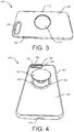
- FIG. 3 illustrates a back view of protective case 100 . Outer surface 130 of protective case 100 is visible in FIG. 3 .
- FIG. 4 illustrates a back perspective view of protective case 100 with device grip 190 installed.
- an electronic device 180 is installed in protective case 100 in FIG. 4 and can be partially seen through camera aperture 150 .
- Electronic device 180 may be any type of phone, smartphone, tablet computer, gaming device, portable electronic device, audio player, video player, camera, portable computer, two-way radio, GPS receiver, and/or other portable device.
- Camera aperture 150 provides optical access for at least a camera lens 181 and/or a flash 182 of electronic device 180 . Many other camera, flash, and lens configurations are possible.
- device grip 190 attaches directly to a back surface of electronic device 180 through grip aperture 140 .
- protective case 100 does not interfere with the attachment of device grip 190 to electronic device 180 .
- Device grip 190 can be attached to electronic device 180 in the same manner and position as it would be if protective case 100 was not present.
- device grip 190 is illustrated in an extended, partially extended, or use position.
- FIG. 4 also illustrates an access port 170 for accessing an electrical interface of installed electronic device 180 (electrical interface not visible).
- the electrical interface may be for transmitting and/or receiving electrical data communication signals and/or power to/from electronic device 180 .
- the electrical interface may include or may be configured to mate with a standardized electrical plug or connector such as, for example, a USB connector, a mini USB connector, a micro USB connector, an APPLE LIGHTNING® connector, a proprietary electronic connector, and/or an electrical connector of another type.
- Protective case 100 may also permit access to other features of installed electronic device 180 .
- protective case 100 may permit access to an audio feature of electronic device 180 , such as a speaker or headphone jack of electronic device 180 .
- protective case 100 may include an aperture with a water impermeable membrane that allows sound to pass through the membrane while keeping water from passing through the associated aperture.
- FIG. 5 illustrates a back perspective view of protective case 100 and device grip 190 in use by a user. Similar to FIG. 4 , device grip 190 is in an extended position, or partially extended position, that enables the user to more reliably, more easily, and/or more steadily hold protective case 100 and installed electronic device 180 . The user places one or two fingers around or under grip end 191 of device grip 190 in order to hold electronic device 180 . Since expanding portion 192 of device grip 190 has a smaller diameter or smaller cross section than grip end 191 , it is easier for the user to hold installed electronic device 180 and the chances of dropping it are reduced.
- FIG. 6 illustrates a back perspective view of protective case 100 and device grip 190 in a viewing configuration on a surface 210 .
- Surface 210 may be a desk, table, or tray on which a user wishes to position in order to view it without having to hold it.
- expanding portion 192 of device grip 190 may pivot, flex, or snap in multiple directions to adjusting the resulting viewing angle of installed electronic device 180 .
- protective case 100 permits this use and operation of device grip 190 and electronic device 180 to occur in a same or similar manner as it would if protective case 100 were not present.
- FIG. 7 illustrates a back view of protective case 100 with electronic device 180 and device grip 190 in a non-extended position.
- This non-extended position may also be referred to as a stowed position, a storage position, a stored position, or a non-use position.
- FIG. 8 provides a side view of the configuration of FIG. 7 .
- back surface 130 of protective case 100 has a shape or contour that makes back surface 130 flush, substantially flush, or significantly flush with grip end 191 of device grip 190 when it is in the non-extended position. Because device grip 190 can be compressed to only a certain minimum height, without the improvements disclosed herein device grip 190 would extend past back surface 130 even in the stowed position.
- the resulting lip or edge of grip end 191 could make it difficult to slide the assembly in and out of pockets or bags and could result in unwanted snagging or catching. Further, a significant gap between an edge of grip end 191 and grip aperture 140 could be a path for dust, water, snow, mud, or debris to get inside protective case 100 .
- back surface 130 extends up to meet the edge of grip end 191 at grip aperture 140 in order to provide a smoother back surface for the overall assembly even though protective case may have an overall or envelope thickness that is greater than it may otherwise have.
- the generally smoother overall envelope reduces or minimizes snagging or catching on pockets, bags, or other items when device grip 190 is in the non-extended position. This configuration may also provide a better overall aesthetic appearance.
- protective case 100 accommodates existing device grips, such as device grip 190 , which may have a minimum thickness that is greater than a minimum back wall thickness of protective case 100 . It should be noted that many shapes or contours of back surface 130 are possible as long as a smooth, somewhat smooth, flush, or somewhat flush interface is created between back surface 130 and grip end 191 at an edge of grip aperture 140 .
- a thickness of the back wall of protective case 100 proximate grip aperture 140 is greater than thicknesses of other portions of the back wall such that outer surface 130 is approximately flush with grip end 191 when the device grip 190 is attached to the installed electronic device and is in a non-extended position.
- outer surface 130 of the back wall of body 110 is non-planar such that outer surface 130 is approximately or substantially flush with grip end 191 when device grip 190 is attached to the installed electronic device and is in a non-extended position.
- outer surface 130 of the back wall of body 110 of protective case 100 has a non-planar shape and is configured such that an outer edge of grip aperture 140 is proximate a distal end of the device grip 190 when device grip 190 is attached to the installed electronic device at a proximal end and is in a storage position.
- protective case 100 may be removable from electronic device 180 without removing device grip 190 . This may be beneficial if an adhesive used to attach device grip 190 to electronic device 180 is permanent or semi-permanent.
- Variations may include varying: a position of grip aperture 140 , a shape of grip aperture 140 , a size of grip aperture 140 , a quantity of grip apertures, the thickness of the back wall of protective case 100 , and/or one or more contours of back surface 130 .
- the contour(s) may result in solid, hollow, or partially hollow portions of the back wall.
- a position of grip aperture 140 may be chosen based on known weight distribution characteristics of electronic device 180 and/or protective case 100 to achieve desired balance characteristics. In other examples, a position of grip aperture 140 may be chosen to improve or optimize use of an associated grip as a stand.
- back surface 130 may include colors or graphics which match or contrast with colors of graphics on grip end 191 .
- a non-round grip aperture may be used to better facilitate alignment or orientation of graphics.
- protective case 100 is intended to work with already existing device grip designs, in some situations different lengths of device grips may be produced or offered to take into account or accommodate a thickness of protective case 100 such that the usable thickness of the extended device grip (see FIG. 5 ) is the same or similar as it would be in a standard installation in which no protective case was present.
- one or more contours of back may be chosen to better fit an inside of a user's hand or partially bent fingers in addition to accomplishing the other objectives disclosed herein.
- the back surface of protective case 100 may be curved to better fit a user's hand as well as provide a flush fit, or near flush fit, for a stowed device grip.
- each of grip aperture 140 and/or device grip 190 may include a gasket and/or gasket seat to form a dust-resistant, dustproof, water-resistant, waterproof, mud-resistant, mudproof, snow-resistant, and/or snowproof seal when device grip 190 is in the non-extended or stowed position.
- a gasket and/or gasket seat to form a dust-resistant, dustproof, water-resistant, waterproof, mud-resistant, mudproof, snow-resistant, and/or snowproof seal when device grip 190 is in the non-extended or stowed position.
- one or more areas of the edge of grip aperture 140 and/or grip end 191 may contain a small recess, cutout, gap, or notch which enables a user to get a fingernail or thin object between them to more easily extend it while providing minimal reduction of benefit to overall smooth, non-catching contour of the solution.
- the recess may be formed in grip aperture 140 and/or grip end 191 . This recess may be in one particular area or in multiple distinct locations around the perimeter (for example, in two, three, or four locations). In other examples, a recess which facilitates extending of device grip 190 may exist around the entire perimeter of grip aperture 140 and/or grip end 191 . In some examples, this feature may be implemented through use of a beveled or rounded edge in a specific area or the entire perimeter of grip aperture 140 and/or grip end 191 .
- protective case 100 may include a removable plug to plug, close, or cover grip aperture 140 if not used and/or when not in use.
- this plug may be formed as a part of body 110 such that it stays in place if a user does not use this option.
- FIG. 9A illustrates a protective case 900 and a device grip cap 920 .
- Protective case 900 is a protective case or cover for an electronic device, such as a smartphone or tablet computer, and may have any of the features, functions, and/or characteristics of protective case 100 .
- protective case 900 may not necessarily include grip aperture 140 and/or may not have a thicker region, sloped region, or contoured region which provides a smooth interface up to a top edge of an installed device grip.
- device grip cap 920 provides an alternative solution that also provides a generally, most, substantially, or primarily smooth outer surface when device grip 190 is not in use in order to reduce the chances of it catching or snagging on edges of a pocket, bag, or other item.
- FIG. 9B illustrates an end cross-sectional view of device grip cap 920 installed over a device grip 190 that is attached to protective case 900 .
- device grip 190 is in the stowed or non-use position.
- Device grip 190 includes a tapered, accordion-like structure that allows it to be compressed or compacted when not in use.
- Device grip cap 920 fits over device grip 190 such that the back surface of the overall assembly is generally smooth, or at least smoother than it would be were device grip cap 920 not present. In this way, inadvertent snagging or catching of device grip 190 on another object is reduced when device grip 190 is in the stowed position.
- This configuration makes the overall assembly easier to slide in and out of pockets, bags, and/or similar storage areas.
- Device grip cap 920 may be made of any material or combination of materials and may be attached to device grip 190 using any known method. In some examples, device grip cap 920 may have one or more transparent regions which allow a logo or graphics on a top of device grip 190 to remain visible even though device grip cap 920 is installed over it. Device grip cap 920 may have a shape, contours, and/or features that are different than those illustrated in FIGS. 9A-9D while still using the same techniques and/or achieving similar results.
- FIG. 9C illustrates an end view of protective case 900 and device grip cap 920 installed over device grip 190 .
- FIG. 9D illustrates device grip cap 920 including an opening feature 925 .
- Opening feature 925 may be any feature which makes it easier to get a finger-hold or grip on device grip cap 920 to pull it and device grip 190 to the unstowed position.
- Opening feature 925 may include a cutout, slot, hole, recess, ridge, protrusion, lip, and/or textured surface for getting a better grip on device grip cap 920 for deployment. Multiple instances of opening feature 925 may be distributed around the perimeter of device grip cap 920 .
- Opening feature 925 may also be configured for use with a small tool in addition to, or in place of, operation using a finger.
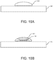
- FIG. 10A illustrates protective case 900 and a bistable cap 1020 .
- Bistable cap 1020 provides an alternative solution for providing a generally smooth outer surface when device grip 190 is not in use in order to reduce the chances of it snagging on edges of a pocket, bag, or other item.
- FIG. 10B illustrates an end cross-sectional view of bistable cap 1020 installed over a device grip 190 that is attached to protective case 900 .
- device grip 190 is in the stowed or non-use position. It includes a tapered, accordion-like structure that allows it to be compressed when not in use.
- Bistable cap 1020 fits over device grip 190 such that the back surface of the overall assembly is generally smooth, or at least smoother than it would be if bistable cap 1020 not present. In this way, inadvertent snagging or catching of device grip 190 is reduced when device grip 190 is in the stowed position.
- Bistable cap 1020 may be made of any material or combination of materials and may be attached to device grip 190 using any known method.
- Bistable cap 1020 generally has two stable states or positions, which are illustrated in FIGS. 10A-10C .
- bistable cap 1020 has a shape similar to a portion of a sphere or dome with a concave side and convex side and can be reversibly reconfigured such that the concave and convex sides are alternated. In other words, it may be a portion of a dome or sphere that can be turned ‘inside out.’
- bistable cap 1020 may not necessarily be spherical.
- Bistable cap 1020 may have a shape, contours, and/or features that are different than those illustrated in FIGS. 10A-10C .
- bistable cap 1020 When a user wishes to use device grip 190 , a center portion of bistable cap 1020 is pressed with a finger or other object in a generally downward direction. This externally applied force or pressure causes bistable cap to 1020 transition to the other of its two stable states, as illustrated in FIG. 10C . It temporarily remains in this state to allow a user to access and/or use device grip 190 . When the user is finished, one or more edges of bistable cap 1020 are pressed to cause it to return to the initial state illustrated in FIG. 10A .
- Device grip cap 920 and/or bistable cap 1020 may also be removable or replaceable and may include graphics, colors, pictures, and/or patterns that are selected to complement or coordinate with protective case 100 .
- FIGS. 9A-9D and 10A-10C are illustrated with respect to a protective case 900 , any of the elements or features may be implemented or used with a protective case.
- any of device grip 190 , device grip cap 920 , and/or bistable cap 1020 may be used directly with an electronic device even though no protective case is present.
- device grip 190 may be attached directly to a back surface of the electronic device.
- the term ‘housing’ may be used herein to refer to either the primary housing of an electronic device and/or a supplemental protective case or cover for an electronic device.
- FIG. 11 illustrates a back view of a protective case 1100 with device grip 190 in a stowed position.
- Protective case 1100 may contain any of the features, functions, elements, and/or characteristics of previously described protective case 100 and/or protective case 900 .
- an electronic device is removably insertable into protective case 1100 from an opposite side of protective case 1100 (from the side facing into the page in FIG. 11 ).
- Sides 1112 of protective case 1100 hold the electronic device in protective case 1100 and may be flexible or pliable.
- Other protective case configurations are possible.
- Back surface 1110 of protective case 1100 has a shape which includes contours selected to better accommodate grip 190 .
- back surface 1110 includes a concave area 1118 in which device grip 190 is attached to protective case 1100 .
- Concave area 1118 may also be described as a recess, a recessed area, and/or a cavity.
- this configuration provides a smoother overall surface or envelope of protective case 1100 , including device grip 190 .
- stowed device grip 190 may be completely flush with back surface 1110 . In other examples, stowed device grip 190 may be partially or substantially flush with back surface 1110 .
- Back surface 1110 of protective case 1100 may include a shape or contours that slope upward from the sides 1112 of protective case 1100 to the edge of concave area 1118 .
- An inner surface of protective case 1100 may include a similar corresponding shape or contour. The sloped back surface and contours provide the space necessary between back surface 1110 and a back surface of an installed electronic device to recess concave area 1118 between them.
- a top edge of stowed device grip 190 may be fully within concave area 1118 and may be below a plane of the upper rim or edge of concave area 1118 .
- stowed device grip 190 may be sufficiently recessed to not contact the flat surface.
- stowed device grip 190 may be flush with back surface 1110 or may extend slightly above the edges of concave area 1118 even when in the stowed position.
- a gap, opening, or slot between a top edge of stowed device grip 190 and the rim or edge of recessed area 1118 .
- This gap or opening makes it easier to for a user to grasp an edge of stowed device grip 190 to pull it out to the extended position.
- This gap, opening, or slot may extend all the way around device grip 190 or may be limited to a portion of recessed area 1118 and/or device grip 190 .
- FIG. 12 illustrates protective case 1100 with device grip 190 is an extended or use position.
- This configuration may provide many advantages as discussed in the examples of FIGS. 4-6 and elsewhere herein.
- device grip 190 extends significantly beyond concave area 1118 so it can be used for holding or supporting protective case 1100 in various ways. Expanding portion 192 of device grip 190 is also visible in FIG. 12 . While device grip 190 and concave area 1118 are round in these examples, other compatible shapes are possible including oval, square, rectangular, triangular, or any polygon.
- FIG. 13 illustrates a front perspective view of protective case 1100 which illustrates inside surface 1111 of protective case 1100 .
- An opposing or back side of concave area 1118 is also visible on inside surface 1111 .
- this internal structure or shape is not necessary and inside surface may be flat or planar.
- the back wall of protective case 100 may vary in thickness to provide the desired contour and/or a cavity may exist between inside surface 1111 and outside surface 1110 .
- FIG. 14 illustrates protective case 1100 with device grip 190 detached.
- Device grip 190 is illustrated with expanding portion 192 in a collapsed position.
- a receiver 193 is visible on back surface 1110 in concave area 1118 .
- Receiver 193 may be any type of mechanical structure or feature configured to removably engage with and/or removably attach to an attachment feature 194 of device grip 190 .
- Receiver 193 and attachment feature 194 may include any features or elements which allow them to temporarily engage, connect, attach, or interface, but also be selectively disengaged, disconnected, and/or detached.
- Receiver 193 may be molded as part of protective case 1100 or may be a separate element that is adhered to or affixed to protective case 1100 . In other examples, receiver 193 may be a separate component that becomes affixed to protective case 1100 as part of a molding process of protective case 1100 . Other configurations are possible.
- device grip 190 may be used with an electronic device without have to adhere it directly to the electronic device.
- device grip 190 may be collapsed or stowed partially or completely into concave area 1118 when not in use thereby reducing unwanted catching or snagging on other objects.
- device grip 190 is readily removable from the protective case. It may be desirable to remove the device grip for a number of reasons including: because it is not expected to be used in the near future, in order to switch to a different device grip having different colors, graphics, or features, and/or to replace a broken device grip.
- Attachment feature 194 of device grip 190 may attached to receiver 193 in a variety of ways.
- the two elements may utilize rotary engage features that attach or detach by rotating the two elements with respect to each other.
- One or both components may also include retention features which cause them engage in a manner in which they click or snap into place and require additional force for removal.
- Device grip 190 may be configured such that the top 191 only engages attachment feature 194 to rotatably remove when device grip 190 is in the collapsed position and/or when a downward force is applied. In this way, device grip 190 may only be removable when it is in the collapsed position and may reduce the chances of unintended detachment.
- FIG. 15 illustrates a back view of a protective case 1500 with device grip 190 in a stowed position.
- Protective case 1500 may contain any of the features, functions, elements, and/or characteristics of previously described protective case 100 , protective case 900 , and/or protective case 1100 .
- an electronic device is removably insertable into protective case 1500 from an opposite side of protective case 1500 (from the side facing into the page in FIG. 15 ).
- FIG. 16 illustrates protective case 1500 with device grip 190 in an extended or use position.
- This configuration may provide advantages similar to those discussed with respect to the examples of FIGS. 4-6 and elsewhere herein.
- device grip 190 extends so it can be used for holding or supporting protective case 1500 in various ways. Expanding portion 192 of grip 190 is also visible in FIG. 16 .
- FIG. 16 illustrates that back surface 1510 of protective case 1500 includes a cutout or recess 1518 that corresponds a size and shape of device grip 190 . Recess 1518 allows at least a portion of device grip 190 to be recessed with respect to back surface 1510 such that device grip 190 protrudes less than it otherwise would when it is in the stowed position.
- FIG. 17 illustrates protective case 1500 with device grip 190 detached.
- Device grip 190 is illustrated with expanding portion 192 in a collapsed position.
- a receiver 193 is visible on back surface 1510 in recessed area 1518 .
- Receiver 193 may be molded as part of protective case 1500 or may be a separate element that is adhered to or affixed to protective case 1500 . In other examples, receiver 193 may be a separate component that becomes affixed to protective case 1500 as part of the molding process of protective case 1500 .
- device grip 190 may be used with an electronic device without have to adhere it directly to the electronic device.
- device grip 190 may be collapsed or stowed partially into recessed area 1518 when not in use to reduce unwanted catching of it on other objects, such as the edge of a person's pocket.
- device grip 190 is readily removable from the protective case. It may be desirable to remove the device grip for a number of reasons including: because it is not expected to be used in the near future, in order to switch to a different device grip, and/or to replace a broken device grip. In some examples, a user may wish to switch between device grips having different colors or graphics.
- FIG. 18 illustrates the configuration of FIG. 17 with protective case 1500 further disassembled.
- Protective case 1500 includes an inner shell 1501 and an outer layer 1502 that fits over inner shell 1501 .
- outer layer 1502 may be a pliable cushion layer.
- Inner shell 1501 includes receiver 193 and recessed area 1518 .
- Outer layer 1502 includes an opening or aperture 1507 that coincides with recessed area 1518 and device grip 190 when attached. This configuration allows device grip 190 to be at least partially recessed into protective case 1500 in in order to reduce the amount it protrudes when in the stowed position while still leaving enough of it accessible so a user can grasp it with a fingertip or fingernail.
- Various components described herein may be manufactured, provided, or sold in the form of a system or a kit.
- the system or kit may include any combination of: a protective case or cover having any combination of the features described herein and a compatible device grip.
- the system or kit need not include every component or feature described herein.
- phrases “in some embodiments,” “according to some embodiments,” “in the embodiments shown,” “in other embodiments,” “in some examples,” “in other examples,” “in some cases,” “in some situations,” “in one configuration,” “in another configuration,” and the like generally mean that the particular technique, feature, structure, or characteristic following the phrase is included in at least one embodiment of the present invention and/or may be included in more than one embodiment of the present invention. In addition, such phrases do not necessarily refer to the same embodiments or to different embodiments.
Landscapes
- Casings For Electric Apparatus (AREA)
- Telephone Set Structure (AREA)
Abstract
Description
Claims (20)
Priority Applications (1)
| Application Number | Priority Date | Filing Date | Title |
|---|---|---|---|
| US16/423,390 US10694835B2 (en) | 2018-03-15 | 2019-05-28 | Protective case for use with device grip |
Applications Claiming Priority (5)
| Application Number | Priority Date | Filing Date | Title |
|---|---|---|---|
| US201862643429P | 2018-03-15 | 2018-03-15 | |
| US201862663316P | 2018-04-27 | 2018-04-27 | |
| US201862782919P | 2018-12-20 | 2018-12-20 | |
| US16/275,969 US10750844B2 (en) | 2018-03-15 | 2019-02-14 | Protective case for use with device grip |
| US16/423,390 US10694835B2 (en) | 2018-03-15 | 2019-05-28 | Protective case for use with device grip |
Related Parent Applications (1)
| Application Number | Title | Priority Date | Filing Date |
|---|---|---|---|
| US16/275,969 Continuation US10750844B2 (en) | 2018-03-15 | 2019-02-14 | Protective case for use with device grip |
Publications (2)
| Publication Number | Publication Date |
|---|---|
| US20190281961A1 US20190281961A1 (en) | 2019-09-19 |
| US10694835B2 true US10694835B2 (en) | 2020-06-30 |
Family
ID=67904645
Family Applications (1)
| Application Number | Title | Priority Date | Filing Date |
|---|---|---|---|
| US16/423,390 Active US10694835B2 (en) | 2018-03-15 | 2019-05-28 | Protective case for use with device grip |
Country Status (1)
| Country | Link |
|---|---|
| US (1) | US10694835B2 (en) |
Cited By (19)
| Publication number | Priority date | Publication date | Assignee | Title |
|---|---|---|---|---|
| US10784914B1 (en) * | 2019-09-19 | 2020-09-22 | Jin Woo Kim | Smart mobile phone shell |
| USD897329S1 (en) * | 2019-07-02 | 2020-09-29 | Otter Products, Llc | Case for a smartphone |
| USD928771S1 (en) * | 2019-01-07 | 2021-08-24 | Popsockets Llc | Grip and stand accessory for personal electronic device |
| US20210301976A1 (en) * | 2018-08-02 | 2021-09-30 | Popsockets Llc | Mobile accessory grip with magnetic locking feature |
| US11186337B1 (en) * | 2020-05-29 | 2021-11-30 | Leslie Ronald Hamilton | Retaining assembly to attach one or more mobile devices to a mobile object |
| US20220166455A1 (en) * | 2020-08-26 | 2022-05-26 | Ye Seul KIM | Accessory for Electronic Device |
| US11403992B2 (en) * | 2018-03-03 | 2022-08-02 | Daniel Neale Gess | Multi positional attachable handle with integrated backlight illumination <<bias>> system |
| US11490713B2 (en) * | 2020-05-22 | 2022-11-08 | Theo Andreas Stewart-Stand | Collapsible drinking cup |
| US11530779B2 (en) | 2020-10-21 | 2022-12-20 | Black Jet Innovations, Inc. | Mobile device grip and stand |
| USD977470S1 (en) * | 2020-06-02 | 2023-02-07 | Bytech IP Holdings, LLC | Expandable electronic device accessory |
| USD980204S1 (en) * | 2021-05-28 | 2023-03-07 | Popsockets Llc | Phone case with positionable accessory |
| USD1019626S1 (en) * | 2020-12-30 | 2024-03-26 | Samsung Electronics Co., Ltd. | Case for mobile telephone |
| US20240148120A1 (en) * | 2022-11-09 | 2024-05-09 | Otter Products, Llc | Protective case with grip and stand |
| USD1053181S1 (en) * | 2024-06-03 | 2024-12-03 | Zhisen Gong | Mobile phone holder |
| USD1062716S1 (en) | 2023-03-07 | 2025-02-18 | Ihdsolutions Llc | Holder accessory for a mobile device |
| US12395201B2 (en) | 2020-09-22 | 2025-08-19 | Brian Robert Balderston | Adaptive support accessory for mobile devices |
| US12433391B2 (en) | 2021-03-29 | 2025-10-07 | Otter Products, Llc | Collapsible and extendable device grip |
| USD1098094S1 (en) * | 2021-10-13 | 2025-10-14 | Popsockets Llc | Mobile electronic device grip with round base |
| US20260025453A1 (en) * | 2024-07-19 | 2026-01-22 | Sharon Heard Moss | Charm Holder Grip Device |
Families Citing this family (13)
| Publication number | Priority date | Publication date | Assignee | Title |
|---|---|---|---|---|
| US10800024B2 (en) * | 2010-08-19 | 2020-10-13 | Michael Shayne KARMATZ | Compacting grip for handheld devices |
| US20250050492A1 (en) * | 2010-10-26 | 2025-02-13 | Michael Shayne KARMATZ | Compacting grip for handheld devices |
| US9804636B2 (en) | 2012-03-14 | 2017-10-31 | David B. Barnett | Docking connector platform for mobile electronic devices |
| US12596402B2 (en) | 2012-03-14 | 2026-04-07 | Popsockets Llc | Docking connector platform for mobile electronic devices |
| US12363212B2 (en) | 2018-01-08 | 2025-07-15 | Popsocket Llc | Magnetic wallet accessory |
| US10244854B1 (en) * | 2018-01-12 | 2019-04-02 | Tzumi Electronics LLC | Gripping apparatus for handheld devices |
| US10694835B2 (en) * | 2018-03-15 | 2020-06-30 | Otter Products, Llc | Protective case for use with device grip |
| US10750844B2 (en) * | 2018-03-15 | 2020-08-25 | Otter Products, Llc | Protective case for use with device grip |
| CN113302426A (en) | 2019-01-18 | 2021-08-24 | 鲍勃斯科特有限责任公司 | Grip for foldable electronic device |
| US10774871B1 (en) * | 2019-03-15 | 2020-09-15 | Quest Usa Corp. | Sliding hinge collapsible discs |
| US11641417B2 (en) * | 2020-08-26 | 2023-05-02 | Push Product Design, LLC | Grip and support attachment for handheld electronic devices |
| USD1056886S1 (en) * | 2023-11-23 | 2025-01-07 | Dongguan Shenhai Sporting Goods Co., Ltd | Waterproof phone case |
| USD1041461S1 (en) * | 2024-05-23 | 2024-09-10 | Zhiwei Wu | Cell phone protector case |
Citations (372)
| Publication number | Priority date | Publication date | Assignee | Title |
|---|---|---|---|---|
| FR935529A (en) | 1946-10-31 | 1948-06-22 | Clasp for handbags and similar items | |
| US3023885A (en) | 1960-03-07 | 1962-03-06 | Bemis Bro Bag Co | Package for delicate articles |
| US3480310A (en) | 1967-09-29 | 1969-11-25 | North American Rockwell | Quick detachable coupling |
| US3521216A (en) | 1968-06-19 | 1970-07-21 | Manuel Jerair Tolegian | Magnetic plug and socket assembly |
| US3786391A (en) | 1972-07-11 | 1974-01-15 | W Mathauser | Magnetic self-aligning electrical connector |
| US3808577A (en) | 1973-03-05 | 1974-04-30 | W Mathauser | Magnetic self-aligning quick-disconnect for a telephone or other communications equipment |
| US3810258A (en) | 1972-07-11 | 1974-05-07 | W Mathauser | Quick connect electrical coupler |
| US3816679A (en) | 1973-07-23 | 1974-06-11 | J Hotchkiss | Magnetically operated electrical connector |
| US4029999A (en) | 1975-04-10 | 1977-06-14 | Ibm Corporation | Thermally conducting elastomeric device |
| US4097878A (en) | 1976-02-06 | 1978-06-27 | Alfons Cramer | Underwater housing for photographic cameras |
| US4182558A (en) | 1976-12-25 | 1980-01-08 | Olympus Optical Co., Ltd. | Camera mounting device for an endoscope |
| US4431333A (en) | 1982-04-14 | 1984-02-14 | The United States Of America As Represented By The Administrator Of The National Aeronautics And Space Administration | Apparatus for releasably connecting first and second objects in predetermined space relationship |
| US4584718A (en) | 1983-03-31 | 1986-04-22 | Product Masters, Inc. | Waterproof enclosure for portable radio or tape player |
| US4856658A (en) | 1988-04-25 | 1989-08-15 | Miloslav Novak | Remote control unit holder assembly |
| US4859110A (en) | 1988-09-21 | 1989-08-22 | Neapco, Inc. | Automatic coupling device |
| US4925146A (en) | 1985-10-28 | 1990-05-15 | David Hegarty | Multi-positionable document support stand and interlocking modular document holder |
| US4933988A (en) | 1987-10-15 | 1990-06-12 | Thibault Gerard J | Audio receiver and detachable battery pack |
| US4940414A (en) | 1988-09-20 | 1990-07-10 | Namsung Electronics Corp. | Antitheft car audio set with removable control box |
| US4963902A (en) | 1988-01-19 | 1990-10-16 | Canon Kabushiki Kaisha | Camera system |
| US4981243A (en) | 1989-04-21 | 1991-01-01 | Rogowski Anthony J | Audio equipment carrier asssembly for handlebars |
| US4994829A (en) | 1989-07-10 | 1991-02-19 | Nikon Corporation | Waterproof camera and lens mount therefore |
| US5025921A (en) | 1990-08-17 | 1991-06-25 | Motorola, Inc. | Environmental radio guard |
| US5054733A (en) | 1990-02-14 | 1991-10-08 | Shields Michael P | Container support device |
| US5123044A (en) | 1990-01-10 | 1992-06-16 | Tate Marc B | Protective cover for a mobile telephone |
| US5138523A (en) | 1991-10-18 | 1992-08-11 | International Business Machines Corporation | Digitizer tablet having cooling apparatus with base and integrated heat sink |
| WO1994000037A1 (en) | 1992-06-24 | 1994-01-06 | Cad Forms Technology Inc. | A pen based computer protective case |
| US5360108A (en) | 1993-08-24 | 1994-11-01 | Sedi S.R.L. | Electronic device shock absorber |
| US5359756A (en) | 1993-01-26 | 1994-11-01 | Takata Corporation | Automatic buckling device |
| US5368159A (en) | 1991-06-14 | 1994-11-29 | Daniels S.R.L. | Protection case for remote controls |
| US5380968A (en) | 1993-09-29 | 1995-01-10 | A.P.M. Hexseal Corporation | Protective cover for switches |
| US5383091A (en) | 1993-02-22 | 1995-01-17 | Sony Electronics, Inc. | Grip and protective casing for cellular telephone |
| US5386084A (en) | 1993-07-22 | 1995-01-31 | Ii Morrow Inc. | Electronic device enclosure |
| US5388692A (en) | 1994-01-03 | 1995-02-14 | Withrow; Joseph E. | Lighting cover for a remote control unit |
| US5388691A (en) | 1993-10-21 | 1995-02-14 | White; Nona J. | Protective case for remote control transmitter |
| USD365927S (en) | 1995-01-31 | 1996-01-09 | Summit Company Ltd. | Protective boot for a digital multimeter |
| US5508479A (en) | 1994-11-17 | 1996-04-16 | Schooley; John L. | Elastomeric rocker switch assembly |
| US5541813A (en) | 1992-03-12 | 1996-07-30 | Hitachi, Ltd. | Portable telephone apparatus having case with wiring member embedded in a molded plastic hinge |
| US5604050A (en) | 1995-06-13 | 1997-02-18 | Motorola Inc. | Latching mechanism and method of latching thereby |
| US5664292A (en) | 1996-08-22 | 1997-09-09 | E Lead Electronic Co., Ltd. | Separable clip assembly |
| US5671120A (en) | 1996-02-07 | 1997-09-23 | Lextron Systems, Inc. | Passively cooled PC heat stack having a heat-conductive structure between a CPU on a motherboard and a heat sink |
| WO1999041958A1 (en) | 1998-02-16 | 1999-08-19 | Sony Computer Entertainment Inc. | Protective case for portable electronic apparatus |
| US5992807A (en) | 1996-06-27 | 1999-11-30 | Intec - Srl | Universal magnetic stand for cell phones |
| US5996956A (en) | 1997-06-17 | 1999-12-07 | Shawver; Michael | Mounting platform for an electronic device |
| US6097593A (en) | 1998-08-14 | 2000-08-01 | Digital Equipment Corporation | Semi-mobile desktop personal computer |
| US6115248A (en) | 1999-05-17 | 2000-09-05 | Palm, Inc. | Detachable securement of an accessory device to a handheld computer |
| US6135408A (en) | 1999-06-19 | 2000-10-24 | Richter; Herbert | Mobile telephone holder |
| US6151206A (en) | 1997-09-29 | 2000-11-21 | Sony Corporation | Electronic device |
| US6149116A (en) | 1999-02-12 | 2000-11-21 | D.L. Telecom Co. Ltd. | Holder for mobile telephone |
| US20010000617A1 (en) | 1996-01-05 | 2001-05-03 | Tracy David S. | Self locking bi-directional lock/release fixture |
| US6302617B1 (en) | 1996-08-20 | 2001-10-16 | Gerhard Rumpp | Coupling device for a vehicle |
| US6305588B1 (en) | 1999-03-17 | 2001-10-23 | Mitsubishi Electric France | Releasable coupling for a suspension stud on a wall of a mobile telephone |
| US6305656B1 (en) | 1999-02-26 | 2001-10-23 | Dash-It Usa Inc. | Magnetic coupler and various embodiments thereof |
| US6311017B1 (en) | 1997-03-11 | 2001-10-30 | Nikon Corporation | Waterproof housing for a device adapted to receive a removable sub-assembly |
| US6317313B1 (en) | 1999-11-09 | 2001-11-13 | Interlogix, Inc. | Case and cover for an electronic device |
| US20010054594A1 (en) | 1997-01-24 | 2001-12-27 | Mark P. Stone | Supporting stand for swivel elements |
| US6349824B1 (en) | 1998-06-26 | 2002-02-26 | Asahi Research Corporation | Watertight equipment cover |
| US6375009B1 (en) | 1998-02-10 | 2002-04-23 | Chung Kyun Lee | Bag with a shock absorbing unit |
| US20020065054A1 (en) | 2000-11-29 | 2002-05-30 | Morris Humphreys | Mobile station and elastomeric cover |
| US6409531B1 (en) | 2001-02-12 | 2002-06-25 | Microhelix, Inc. | Easily mated compact connector |
| US20020079244A1 (en) | 2000-12-18 | 2002-06-27 | Addonics Technologies, Inc. | Inner enclosure with micro shock absorber for a carrying case |
| US6445577B1 (en) | 2000-09-20 | 2002-09-03 | 3Com Corporation | Case with communication module having a double pin hinge for a handheld computer system |
| US6456487B1 (en) | 2001-04-30 | 2002-09-24 | Nokia Corporation | Enclosure for wireless communication device |
| US6464524B1 (en) | 1999-07-26 | 2002-10-15 | Angelo Fan Brace Licensing, L.L.C. | Ceiling fan with easy installation features |
| US6490155B2 (en) | 2000-07-07 | 2002-12-03 | Palm, Inc. | Detachable coupling for handheld computer and peripheral attachment scheme |
| US6514624B2 (en) | 2000-02-18 | 2003-02-04 | Dai Nippon Printing Co., Ltd. | Decorative sheet |
| US6545862B1 (en) | 2000-05-25 | 2003-04-08 | Palm, Inc. | Method and system for an interchangeable modular display screen for a portable computing device |
| US20030141329A1 (en) | 2002-01-30 | 2003-07-31 | Daniel Huang | Removable belt clip system |
| US6616111B1 (en) | 2002-08-12 | 2003-09-09 | Gabriel A. White | Hand held electronic device or game impact protector |
| US6625394B2 (en) | 2001-12-21 | 2003-09-23 | Eastman Kodak Company | Two-shot molded seal integrity indicator, underwater camera, and method |
| US6626362B1 (en) | 1999-02-16 | 2003-09-30 | Mark Steiner | Protective cover for a hand held device |
| US6646864B2 (en) | 2001-11-19 | 2003-11-11 | Otter Products, Llc | Protective case for touch screen device |
| US6685493B2 (en) | 2000-01-29 | 2004-02-03 | Zf Friedrichshafen Ag | Electric connector |
| US20040029405A1 (en) | 2000-12-14 | 2004-02-12 | Hermann Neidlein | Electromechanical connecting device |
| US6701159B1 (en) | 2000-03-03 | 2004-03-02 | Andew P. Powell | Jacket for cellular phone |
| US6705580B1 (en) | 2002-12-20 | 2004-03-16 | Daimlerchrysler Corporation | Cup holder for a motor vehicle |
| US6762935B2 (en) | 1999-03-11 | 2004-07-13 | Fujitsu Limited | Electronic apparatus and electric part |
| US20040150945A1 (en) | 2002-11-14 | 2004-08-05 | Hewlett-Packard Development Company, L.P. | Support |
| US6865076B2 (en) | 1999-02-04 | 2005-03-08 | Palmone, Inc. | Electronically-enabled housing apparatus for a computing device |
| US20050088811A1 (en) | 2003-10-22 | 2005-04-28 | Imran Ulla | External battery pack |
| US6888940B1 (en) | 2000-04-12 | 2005-05-03 | Daniel Deppen | Magnetic holder for cell phones and the like |
| US20050213298A1 (en) | 2002-06-19 | 2005-09-29 | Motion Computing, Inc. | Docking support for a tablet computer with extended battery |
| US20050224508A1 (en) | 2004-04-12 | 2005-10-13 | Hitachi Communication Technologies, Ltd. | Case with hinged lid |
| US6966519B2 (en) | 2002-06-13 | 2005-11-22 | Hammerhead Industries | Rotatable retracting apparatus |
| US20050279661A1 (en) | 2003-11-12 | 2005-12-22 | Hodges Richard P | Cover for remote control device |
| US20050284904A1 (en) | 2004-06-29 | 2005-12-29 | Knapp Christopher J | Attachment for portable electronic devices and methods for using the same |
| US20060027718A1 (en) | 2004-08-06 | 2006-02-09 | David Quijano | Apparatuses and methods for supporting peripheral devices |
| US20060066438A1 (en) | 2004-09-27 | 2006-03-30 | David Altounian | Method and system for controllably and selectively securing a portable computing device to a physical holding device |
| US20060086873A1 (en) | 2004-10-27 | 2006-04-27 | E-Lead Electronic Co., Ltd. | Fastening apparatus for a detachable multimedia player of cars |
| US7050841B1 (en) | 2004-08-30 | 2006-05-23 | Hideki Francis Onda | Protective enclosure for a hand-held electronic device that both stores and plays digital audio recordings |
| US7072699B2 (en) | 2000-10-02 | 2006-07-04 | Nokia Corporation | Sliding cover |
| US20060172765A1 (en) | 2005-01-29 | 2006-08-03 | Yosef Lev | Gel filled mobile phone case |
| USD526780S1 (en) | 2004-07-22 | 2006-08-22 | Otter Products, Llc | Case |
| US20060237495A1 (en) | 2005-04-23 | 2006-10-26 | Hon Hai Precision Industry Co., Ltd. | Carry assembly for portable electronic device |
| US20060243679A1 (en) | 2005-04-27 | 2006-11-02 | Mark Dickerson | Computer monitor organizer |
| US20060255493A1 (en) | 2005-05-11 | 2006-11-16 | Sik, Inc. | Apparatus and method for making form-fitted molded protective cases for products |
| US7158376B2 (en) | 2001-11-19 | 2007-01-02 | Otter Products, Llc | Protective enclosure for an interactive flat-panel controlled device |
| US7180735B2 (en) | 2001-11-19 | 2007-02-20 | Otter Products, Llc | Protective enclosure and watertight adapter for an interactive flat-panel controlled device |
| US7194291B2 (en) | 2001-06-26 | 2007-03-20 | Gregory Kim | Protective mask of mobile phone |
| US20070071423A1 (en) | 2005-09-27 | 2007-03-29 | Fantone Stephen J | Underwater adaptive camera housing |
| USD542524S1 (en) | 2004-08-17 | 2007-05-15 | Otter Products, Llc | Box |
| US20070115387A1 (en) | 2005-11-21 | 2007-05-24 | Ho Kenneth K | Underwater camera combination |
| US7230823B2 (en) | 2003-08-20 | 2007-06-12 | Otter Products, Llc | Protective membrane for touch screen device |
| US7236588B2 (en) | 2003-12-12 | 2007-06-26 | Nokia Corporation | Interlocking cover for mobile terminals |
| US20070146985A1 (en) | 2005-08-31 | 2007-06-28 | Two Technologies, Inc | Systems for integrating peripheral devices with hand-held computing devices |
| US20070155448A1 (en) | 2006-01-04 | 2007-07-05 | Jia-Sing Hong | Sliding mechanism of handheld electronic device |
| US20070158220A1 (en) | 2004-01-07 | 2007-07-12 | Cleereman Robert J | Impact-resistant case with sealable opening |
| US20070181620A1 (en) * | 2006-02-09 | 2007-08-09 | Carver William H Iii | Ring system for securing devices |
| US20070215769A1 (en) | 2006-03-15 | 2007-09-20 | The Boeing Company | Retaining member and method for use with a seat track |
| US20070215659A1 (en) | 2006-03-17 | 2007-09-20 | Knapp Christopher J | Connector for portable devices and methods for using the same |
| US7287738B2 (en) | 2000-12-06 | 2007-10-30 | Accessmount Llc | Remotely attachable and separable coupling |
| US7311526B2 (en) | 2005-09-26 | 2007-12-25 | Apple Inc. | Magnetic connector for electronic device |
| US20070297149A1 (en) | 2001-11-19 | 2007-12-27 | Otter Products, Llc | Modular accessory for protective case enclosing touch screen device |
| US7343184B2 (en) | 2006-08-02 | 2008-03-11 | Ramin Rostami | Handheld device protective case |
| US20080083797A1 (en) * | 2006-10-05 | 2008-04-10 | Myers Gregory B | Stick-on security ring for a hand held device |
| US7359184B2 (en) | 2002-10-31 | 2008-04-15 | Hotwire Development Llc | Notebook computer protection device |
| US7374142B2 (en) | 2003-03-27 | 2008-05-20 | Carnevali Jeffrey D | Magnetic mounting apparatus |
| US20080117578A1 (en) | 2006-11-16 | 2008-05-22 | Jerry Moscovitch | Multi-Monitor Support Structure |
| US20080163463A1 (en) | 2007-01-10 | 2008-07-10 | Sunex International, Inc. | Tool handle |
| USD574819S1 (en) | 2007-06-25 | 2008-08-12 | Apple Inc. | Case |
| US20080199252A1 (en) | 2007-02-21 | 2008-08-21 | Sebastian Frey | Coupling mechanism |
| US7431251B2 (en) | 2003-03-27 | 2008-10-07 | Carnevali Jeffrey D | Magnetic mounting platform |
| USD581155S1 (en) | 2007-12-07 | 2008-11-25 | Otter Products, Llc | Case |
| USD581421S1 (en) | 2002-11-19 | 2008-11-25 | Otter Products, Llc | PDA case |
| US20080304692A1 (en) | 2006-01-04 | 2008-12-11 | Yongde Zhang | Portable Speaker Device and Portable Audio Device Player |
| US20090001232A1 (en) | 2007-06-27 | 2009-01-01 | Dong-Min Seo | Mobile device |
| US20090034169A1 (en) | 2001-11-19 | 2009-02-05 | Richardson Curtis R | Detachable pod assembly for protective case |
| USD587008S1 (en) | 2007-12-07 | 2009-02-24 | Otter Products, Llc | Case |
| USD589016S1 (en) | 2007-09-12 | 2009-03-24 | Otter Products, Llc | Phone case |
| US20090079665A1 (en) | 2006-03-14 | 2009-03-26 | Jerry Moscovitch | Power and Video Unit for a Multi-Screen Display System |
| US20090084705A1 (en) | 2007-09-28 | 2009-04-02 | Netalog, Inc. | Multi-function case for portable digital media device |
| US20090161903A1 (en) | 2007-12-21 | 2009-06-25 | Russell Corporation | Docking station capable of being mounted to a sports support pole |
| US7555325B2 (en) | 2001-11-03 | 2009-06-30 | Jean Goros | Protective sleeve for small portable electronic devices |
| US7558594B2 (en) | 2002-07-16 | 2009-07-07 | Nokia Corporation | Flexible cover for a mobile telephone |
| US7575389B2 (en) | 2005-12-08 | 2009-08-18 | Savannah River Nuclear Solutions, Llc | Magnetic coupling device |
| US20090237377A1 (en) | 2008-03-20 | 2009-09-24 | Compal Electronics, Inc. | Electronic device, handheld device and stylus |
| KR200446444Y1 (en) | 2009-03-13 | 2009-10-29 | 여창기 | Protective Cases for Mobile Devices |
| US20090283184A1 (en) | 2008-05-16 | 2009-11-19 | Sun Young Han | Cover with elastic portion for bar-type portable terminal device |
| US20100006468A1 (en) | 2008-07-11 | 2010-01-14 | Fruitshop International Co., Ltd. | Protection cover for portable product |
| US20100078343A1 (en) | 2008-09-30 | 2010-04-01 | Hoellwarth Quin C | Cover for Portable Electronic Device |
| US20100093412A1 (en) | 2008-10-09 | 2010-04-15 | Inside Contactless | Protective envelope for a handheld electronic device |
| US20100090085A1 (en) | 2008-10-10 | 2010-04-15 | Bradley William Corrion | One piece fold flat easel |
| US20100122756A1 (en) | 2008-11-14 | 2010-05-20 | Kip Longinotti-Buitoni | Protective covering for personal electronic device |
| US20100141864A1 (en) | 2008-12-05 | 2010-06-10 | Chih-Huei Lai | Mounting mechanism for fixing computer mainframe |
| US20100147737A1 (en) | 2009-08-21 | 2010-06-17 | Otter Products, Llc | Protective cushion cover for an electronic device |
| US20100181450A1 (en) | 2009-01-16 | 2010-07-22 | Troy Hulick | Accessory attachment mechanism |
| US20100195279A1 (en) | 2007-07-18 | 2010-08-05 | Blue Bee Limited | Docking station and kit for a personal electronic device |
| US20100203931A1 (en) | 2009-02-06 | 2010-08-12 | Bryan Lee Hynecek | One Piece Co-formed Exterior Hard Shell Case with an Elastomeric Liner for Mobile Electronic Devices |
| US20100215188A1 (en) | 2009-02-23 | 2010-08-26 | Clinton Wilcox | Vehicle Mounted Cradle and Sound Amplifier for a Personal Communication Device |
| US20100230301A1 (en) | 2009-03-13 | 2010-09-16 | Zalman Fellig | Carrying receptacle |
| US7845608B1 (en) | 2009-10-22 | 2010-12-07 | Hong Fu Jin Precision Industry (Shenzhen) Co., Ltd. | Mounting apparatus for electronic device |
| US20110031287A1 (en) | 2008-09-09 | 2011-02-10 | Zero Chroma, LLC | Holder for Electronic Device with Support |
| US7907394B2 (en) | 2001-11-19 | 2011-03-15 | Otter Products, Llc | Protective enclosure for touch screen device |
| US20110064401A1 (en) | 2009-09-11 | 2011-03-17 | Desorbo Alexander P | Coupling and accessory system for electronic devices |
| US20110075349A1 (en) | 2009-09-28 | 2011-03-31 | Giga-Byte Technology Co.,Ltd. | Notebook computer docking station |
| US20110073505A1 (en) | 2009-09-29 | 2011-03-31 | Kurt Stiehl | Button mechanisms for electronic device cases |
| US20110073608A1 (en) | 2009-09-30 | 2011-03-31 | Otter Products, Llc | Case |
| US7933122B2 (en) | 2007-06-06 | 2011-04-26 | Otter Products, Llc | Protective enclosure for a computer |
| US20110101058A1 (en) | 2009-05-28 | 2011-05-05 | Tom Heckman | Pivot mount assembly |
| US20110170256A1 (en) | 2008-09-25 | 2011-07-14 | Johann Lee | Docking station with rotation mechanism |
| US20110192857A1 (en) | 2008-12-18 | 2011-08-11 | Wayne Philip Rothbaum | Magnetically Attached Accessories (For A Case) for a Portable Electronics Device |
| US20110216495A1 (en) | 2010-03-04 | 2011-09-08 | Keith Bernard Marx | Docking system for electronic devices |
| US8016107B2 (en) | 2007-12-27 | 2011-09-13 | Timothy Emsky | Holder for portable electronic device |
| US20110228459A1 (en) | 2010-03-17 | 2011-09-22 | Otter Products, Llc | Energy deflection case |
| US20110235846A1 (en) | 2010-03-29 | 2011-09-29 | Hong Fu Jin Precision Industry (Shenzhen) Co., Ltd . | Portable electronic device with detachable speaker |
| US8049727B2 (en) | 2001-10-11 | 2011-11-01 | Hewlett-Packard Development Company, L.P. | Accessory module for handheld devices |
| US20110294556A1 (en) | 2010-05-25 | 2011-12-01 | Jeff Carlberg | Mobile phone case with card slot |
| US20110297566A1 (en) | 2010-06-07 | 2011-12-08 | Targus Group International, Inc. | Portable electronic device case with cleaning accessory |
| US20110314651A1 (en) | 2010-06-28 | 2011-12-29 | A.R.B. Production, Inc. | Open-weave surface patterning to enable touchscreen accessibility in wearable apparatus |
| US20120018325A1 (en) | 2010-07-26 | 2012-01-26 | Sgp Korea | Case for bar type mobile electronic device |
| US20120037524A1 (en) | 2010-08-10 | 2012-02-16 | Lonsdale Ii Thomas J | Protective Case with Substantially-Rigid Outer Layer and Cushioning Inner Layer |
| US20120037536A1 (en) | 2010-08-10 | 2012-02-16 | Cypress Holdings, Ltd. D/B/A Cypress Industries | Protective Case With Sliding Display Cover |
| US20120043235A1 (en) | 2010-08-23 | 2012-02-23 | James Robert Klement | Protective case for portable electrical device |
| US20120074005A1 (en) | 2010-09-24 | 2012-03-29 | Otter Products, Llc | Edge retention for flexible cover |
| US20120092377A1 (en) | 2010-10-18 | 2012-04-19 | Russound/Fmp, Inc. | Media tablet dock integration with room audio system |
| US20120106069A1 (en) | 2007-02-20 | 2012-05-03 | J. S. Karaoke, Llc | System and, method for holding and powering three consumer electronic devices |
| US20120111881A1 (en) | 2010-06-07 | 2012-05-10 | 360 Mobility Solutions, Llc | Protective cases for electronic devices |
| US20120118770A1 (en) * | 2010-11-15 | 2012-05-17 | Valls William H | Tablet accessory |
| US20120170194A1 (en) | 2011-01-05 | 2012-07-05 | Charles Lord | Mobile computer stand |
| US20120175474A1 (en) | 2011-01-06 | 2012-07-12 | Brandon Barnard | Electronic device holder |
| US20120187260A1 (en) | 2011-01-26 | 2012-07-26 | Christopher James Moyer | Mount for Personal Electronic Device |
| US20120252543A1 (en) | 2011-03-30 | 2012-10-04 | Richard Cho | Phone and tablet stand |
| CN202488509U (en) | 2012-02-08 | 2012-10-10 | 许俊溪 | Cellphone protection shell |
| US20120267491A1 (en) | 2011-04-19 | 2012-10-25 | Chiu Ronald On Ho | Locking device |
| US8303336B2 (en) | 2010-01-19 | 2012-11-06 | Smith Benjamin J | Quick mounting device |
| US20120287565A1 (en) | 2011-05-13 | 2012-11-15 | Lightwedge Llc | Case having an interchangeable cover |
| US20120326003A1 (en) | 2011-06-27 | 2012-12-27 | Solow Michael L | Multi-function tablet computer grip with 360-degree rotating finger ringlet |
| US20130027862A1 (en) | 2011-06-13 | 2013-01-31 | Treefrog Developments, Inc. Dba Lifeproof. | Housing for encasing a tablet computer |
| US20130039521A1 (en) | 2011-08-08 | 2013-02-14 | Hon Hai Precision Industry Co., Ltd. | Docking station for electronic device |
| US20130068915A1 (en) | 2011-09-21 | 2013-03-21 | The Joy Factory, Inc. | Detachable mounting systems for electronic devices |
| US20130083953A1 (en) | 2011-09-29 | 2013-04-04 | Yun Yu Chang | Mobile electronic device protective cover with tablet pc and flat speaker support function |
| US20130088813A1 (en) | 2011-10-10 | 2013-04-11 | AFC Trident, Inc. | Modular protective cover with accessory slot for portable electronic device |
| US20130098788A1 (en) | 2011-10-19 | 2013-04-25 | Patrick McCarville | Cell Phone Case |
| US20130107449A1 (en) | 2011-10-28 | 2013-05-02 | Yuan Zi Su | Tablet computer enclosure |
| US20130109253A1 (en) | 2011-11-02 | 2013-05-02 | Weldon Gammon | Tablet device enclosure and method |
| US20130117487A1 (en) | 2011-11-04 | 2013-05-09 | Alco Electronics Limited | Speaker docking station |
| US8442604B1 (en) | 2010-07-16 | 2013-05-14 | Incase Designs Corp. | Camera ring for smartphone case to reduce flash glare |
| US20130126533A1 (en) | 2010-03-31 | 2013-05-23 | Justin Klosky | Water resistant buoyant case for a mobile electronic device |
| US8453835B2 (en) | 2010-06-24 | 2013-06-04 | Kar Ming So | Protective cover for communication device |
| US8453344B2 (en) | 2006-04-21 | 2013-06-04 | Asics Corporation | Shoe sole with reinforcing structure and shoe sole with shock-absorbing structure |
| US8457701B2 (en) | 2010-06-16 | 2013-06-04 | Incase Designs Corp. | Case for portable electronic device |
| US20130177181A1 (en) | 2012-01-09 | 2013-07-11 | In2Uit Inc. Ltd | Protecting case assembly with foldable slim speaker for portable apparatus |
| US20130175186A1 (en) | 2012-01-09 | 2013-07-11 | Case-Mate, Inc. | Case for electronic devices |
| US20130181584A1 (en) | 2012-01-12 | 2013-07-18 | Rokform Llc | Case and mount system for handheld electronic device |
| US8490783B1 (en) | 2013-02-26 | 2013-07-23 | Eagle Fan | Protective cover |
| US8509865B1 (en) | 2012-11-30 | 2013-08-13 | Superior Communications, Inc. | Mobile device with cushion devices |
| US8514568B2 (en) | 2010-12-20 | 2013-08-20 | Hong Fu Jin Precision Industry (Shenzhen) Co., Ltd. | Electronic device having rotatable support |
| US20130220841A1 (en) | 2012-01-10 | 2013-08-29 | The Joy Factory, Inc. | Protective casing providing impact absorption and water resistance for portable electronic devices |
| US20130220847A1 (en) | 2012-01-17 | 2013-08-29 | Roy Roee FISHER | Multipurpose protective case for portable electronic device |
| US20130222989A1 (en) | 2012-02-23 | 2013-08-29 | Yi-Ting Chen | Electronic device |
| US20130230202A1 (en) | 2012-03-02 | 2013-09-05 | Bby Solutions, Inc. | Triangle speaker for tablet computer |
| US20130240578A1 (en) | 2012-03-16 | 2013-09-19 | David Chen Yu | Wrist-based systems and methods to carry mobile device(s) |
| US20130262248A1 (en) | 2012-03-30 | 2013-10-03 | Bixolon Co.,Ltd. | Pos terminal and pos system using mobile terminal |
| US8560031B2 (en) * | 2011-03-16 | 2013-10-15 | David B. Barnett | Extending socket for portable media player |
| US8567599B2 (en) | 2010-01-26 | 2013-10-29 | Modulr Llc | Multifunctional electronic device case |
| US20130292288A1 (en) | 2012-05-02 | 2013-11-07 | W. Paul Willes | Impact protection enclosure for a mobile electronic device |
| US20130292269A1 (en) | 2012-05-04 | 2013-11-07 | A.G. Findings & Mfg. Co., Inc. | Mobile device case having tension elements |
| US20130303000A1 (en) | 2012-05-08 | 2013-11-14 | Otter Products, Llc | Connection mechanism |
| US8599547B2 (en) | 2001-11-19 | 2013-12-03 | Otter Products, Llc | Protective enclosure for electronic device |
| US20130318775A1 (en) | 2012-05-30 | 2013-12-05 | Christopher Peters | System And Method For Mounting A Handheld Electronic Device |
| US20140003647A1 (en) | 2012-06-27 | 2014-01-02 | Keng-Yuan Liu | Magnetic sound box device |
| US20140049142A1 (en) | 2012-08-16 | 2014-02-20 | Otter Products, Llc | Protective enclosure for an electronic device |
| US20140065847A1 (en) | 2012-09-03 | 2014-03-06 | Sagalio, Inc. | Method and system for smart contact arrays |
| US8676281B1 (en) | 2012-03-21 | 2014-03-18 | Valor Communication, Inc. | Interchangeable color backgrounds for cell phone protector cases |
| US20140080553A1 (en) | 2011-04-18 | 2014-03-20 | Mobilicer As | Cover for portable devices adapted to attach modules thereto |
| US20140099526A1 (en) | 2012-10-04 | 2014-04-10 | The Code Corporation | Hand-held electronic device accessory that facilitates rapid battery replacement |
| US20140097102A1 (en) | 2012-10-09 | 2014-04-10 | Speculative Product Design, Llc | Case for a portable electronic device with a reversible retaining clip |
| US20140128132A1 (en) | 2012-10-12 | 2014-05-08 | James L. Cox, III | Case with interchangeable back plates |
| KR101394285B1 (en) | 2013-11-18 | 2014-05-14 | 주식회사 슈피겐코리아 | Connecting device opening and shutting front cover of portable electronic device and case thereof |
| US20140141838A1 (en) | 2012-11-16 | 2014-05-22 | UNU Electronics Inc. | Mobile device case with interchangeable display |
| US8737066B1 (en) * | 2011-06-13 | 2014-05-27 | Mobile Innovations, Inc. | Gripping device and method of use |
| US20140152890A1 (en) | 2012-06-01 | 2014-06-05 | Treefrog Developments, Inc. | Housing for encasing an object having a thin profile |
| US20140168884A1 (en) | 2012-12-05 | 2014-06-19 | Mobile Technologies, Inc. | Docking station for tablet device |
| US20140166707A1 (en) | 2012-12-17 | 2014-06-19 | Philip J. Leisey-Bartsch | Apparatus with rotating disc for electronic devices and the like |
| US20140187289A1 (en) | 2013-01-03 | 2014-07-03 | Headlogic Llc | Modular Components and Methods for an Electronic Device |
| US20140183065A1 (en) | 2012-12-28 | 2014-07-03 | Graphique de France, Ltd. | Cover for mobile telephone |
| US20140183064A1 (en) | 2012-12-29 | 2014-07-03 | Hon Hai Precision Industry Co., Ltd. | Protection case for electronic device |
| US8770402B2 (en) | 2012-01-26 | 2014-07-08 | Iceberg Commerce Inc. | Waterproof protective case for a mobile device |
| US20140200056A1 (en) | 2013-01-11 | 2014-07-17 | WTL (USA) Fund, Inc. | Cell phone protective shell with holder |
| US8800762B2 (en) | 2009-08-12 | 2014-08-12 | Incipio Technologies, Inc. | Protective cases for mobile devices |
| US20140228074A1 (en) | 2013-02-12 | 2014-08-14 | Sonim Technologies, Inc. | Embedded Accessory for Mobile Devices |
| US20140227026A1 (en) | 2013-02-14 | 2014-08-14 | Olloclip, Llc | Accessories for communication devices |
| US8830663B2 (en) | 2010-08-25 | 2014-09-09 | Ligar Group, LLC | Apparatus, system, and method for attaching peripheral items to devices |
| US20140262934A1 (en) | 2013-03-15 | 2014-09-18 | Incipio Technologies, Inc. | Case for mobile device |
| US20140265765A1 (en) | 2013-03-15 | 2014-09-18 | Otter Products, Llc | Releasable mount apparatus and system |
| US20140262848A1 (en) | 2013-03-14 | 2014-09-18 | Incipio Technologies, Inc. | Protective case for mobile device |
| US8844098B2 (en) * | 2010-08-19 | 2014-09-30 | Michael Shayne KARMATZ | Apparatus for gripping handheld devices |
| US20140302896A1 (en) | 2013-04-04 | 2014-10-09 | Ye Xu | Portable Charging System for a Smartphone |
| US20140299488A1 (en) | 2011-07-01 | 2014-10-09 | MCCURDY P. Andrew | Protective case for electronic devices |
| US8875879B2 (en) | 2010-08-10 | 2014-11-04 | Incase Designs Corp. | Case for electronic tablet |
| US20140325818A1 (en) | 2013-05-01 | 2014-11-06 | Gui Global Products, Ltd. | Filled amorphous bag apparatus for positioning screened devices and method for the use thereof |
| US20140355200A1 (en) | 2013-05-30 | 2014-12-04 | Jean-Michel Thiers | Mounting system for electronic device |
| USD722603S1 (en) | 2014-05-30 | 2015-02-17 | Otter Products, Llc | Mount for electronic device |
| US8955678B2 (en) | 2013-03-14 | 2015-02-17 | Pelican Products, Inc. | Protective cases for mobile electronic communication devices |
| US20150061477A1 (en) | 2013-08-27 | 2015-03-05 | Wimo Labs LLC | Mobile device case |
| US20150062787A1 (en) | 2013-08-30 | 2015-03-05 | Wimo Labs LLC | Mobile device case |
| US20150068935A1 (en) | 2013-09-12 | 2015-03-12 | Otter Products, Llc | Protective case with internal suspension system |
| USD725119S1 (en) | 2014-06-02 | 2015-03-24 | Otter Products, Llc | Case for electronic device |
| US20150083615A1 (en) | 2013-09-21 | 2015-03-26 | Otter Products, Llc | Magnetic mounting system for electronic device |
| US9008738B1 (en) | 2012-12-24 | 2015-04-14 | Valor Communication, Inc. | Facilitating a painting or a drawing on an insert card retained within or on a rear surface of a cell phone protector case |
| USD726732S1 (en) | 2014-06-13 | 2015-04-14 | Otter Products, Llc | Case for electronic device |
| US20150111623A1 (en) | 2011-06-09 | 2015-04-23 | Skin-It, Inc. | Method and apparatus for personalizing consumer products |
| US20150133183A1 (en) | 2013-11-13 | 2015-05-14 | Motorola Mobility Llc | Method, Electronic Device, and Accessory for Carrying Out Functions Based on Reflected Electromagnetic Radiation |
| US20150141095A1 (en) | 2013-11-19 | 2015-05-21 | Samyang Cns Co., Ltd. | Flip type case for portable electronic device |
| US20150141090A1 (en) | 2013-11-19 | 2015-05-21 | Great Performance Industries Co., Ltd. | Mobilephone casing |
| US20150153791A1 (en) | 2013-12-02 | 2015-06-04 | Chih-Juh Wong | Protective case for electronic equipment |
| US20150172431A1 (en) | 2013-12-13 | 2015-06-18 | Triangus Group Co., Ltd. | Multifunctional protective case for electronic device |
| US20150189160A1 (en) | 2013-12-31 | 2015-07-02 | Optelec B.V. | Viewing device |
| US20150194997A1 (en) | 2014-01-07 | 2015-07-09 | Otter Products, Llc | Metallic protective case for electronic device |
| US20150194998A1 (en) | 2014-01-07 | 2015-07-09 | Incipio Technologies, Inc. | Protective case for mobile device with integrated latch |
| US20150195938A1 (en) | 2014-01-07 | 2015-07-09 | Otter Products, Llc | Protective enclosure for an electronic device |
| WO2015103599A1 (en) | 2014-01-06 | 2015-07-09 | Zero Chroma, LLC | Systems, methods, and apparatuses for supporting electronic devices |
| US9089056B2 (en) | 2010-10-12 | 2015-07-21 | Treefrog Developments, Inc. | Housing for encasing an object |
| US20150201723A1 (en) | 2013-02-01 | 2015-07-23 | Treefrog Developments, Inc. | Encasements for an electronic device having a biometric scanner |
| US20150214989A1 (en) | 2014-01-29 | 2015-07-30 | Wistron Corp. | Support base for electronic device |
| US20150220766A1 (en) | 2012-10-04 | 2015-08-06 | The Code Corporation | Barcode-reading enhancement system for a computing device that comprises a camera and an illumination system |
| US20150257285A1 (en) | 2013-08-30 | 2015-09-10 | Wimo Labs LLC | Door securement mechanism for waterproof encasement |
| USD739857S1 (en) | 2014-05-22 | 2015-09-29 | Otter Products, Llc | Mount for electronic device |
| US9153112B1 (en) | 2009-12-21 | 2015-10-06 | Masimo Corporation | Modular patient monitor |
| US20150304466A1 (en) | 2012-09-26 | 2015-10-22 | Nec Platforms, Ltd. | Portable information terminal holding stand and desk telephone |
| US20150335138A1 (en) * | 2014-05-23 | 2015-11-26 | Charles D. Juarbe | Carrying Case Assembly |
| US9226057B1 (en) | 2014-05-15 | 2015-12-29 | OIO Tech Inc. | External sound systems with integral flat panel loudspeakers for portable electronic devices |
| US20160007705A1 (en) | 2014-07-08 | 2016-01-14 | Diversified Products, Inc. | Case for a Portable Electronic Device |
| US20160036478A1 (en) | 2014-07-29 | 2016-02-04 | Chih-Juh Wong | Wireless charging stand |
| US20160040825A1 (en) | 2013-03-15 | 2016-02-11 | L. Christopher Franklin | Mounting apparatus |
| US9266664B2 (en) | 2008-06-27 | 2016-02-23 | Switcheasy Limited | Protective case having a hybrid structure for portable handheld electronic devices |
| US9274556B2 (en) | 2011-01-05 | 2016-03-01 | Mophie, Inc. | Tablet computer stand |
| US20160072933A1 (en) | 2014-09-04 | 2016-03-10 | James L. Cox, III | Case with interchangeable back plate |
| US9301584B2 (en) * | 2014-08-14 | 2016-04-05 | Shane Butts | Carrying case assembly |
| US9316344B2 (en) * | 2013-01-07 | 2016-04-19 | Zero Chroma, LLC | Systems, methods, and apparatuses for supporting electronic devices |
| US9316026B2 (en) | 2011-06-14 | 2016-04-19 | ACCO Brands Corporation | Protective case for physically securing a portable electronic device |
| US20160122821A1 (en) | 2013-06-10 | 2016-05-05 | Suregene, Llc | Genetic markers of antipsychotic response |
| US20160142093A1 (en) | 2014-11-14 | 2016-05-19 | Wayne Phang | Protective Case Accessory With Multi-Function Button For Smart-phone Device |
| US20160150861A1 (en) | 2014-12-02 | 2016-06-02 | Aevoe International Ltd. | Mountable case assembly |
| US9367090B2 (en) | 2012-03-14 | 2016-06-14 | Plugged Llc | Docking connector platform for mobile electronic devices |
| US20160179143A1 (en) | 2014-12-23 | 2016-06-23 | Hand Held Products, Inc. | Tablet computer with interface channels |
| US20160183392A1 (en) | 2014-12-19 | 2016-06-23 | Amie Kelley | Electronic Device Holder |
| US9377154B2 (en) | 2013-09-13 | 2016-06-28 | Hon Hai Precision Industry Co., Ltd. | Bracket for supporting electronic device |
| US20160195898A1 (en) | 2015-01-02 | 2016-07-07 | Kensonix Limited | Docking station for a portable electronic device |
| US20160198822A1 (en) | 2013-08-22 | 2016-07-14 | Mi-Sun Lee | Electronic device case having convex surface caused by air injection, diary, and method for manufacturing same |
| US9397719B1 (en) | 2015-06-17 | 2016-07-19 | Airo Collective, Inc. | Mobile device holder |
| USD762258S1 (en) | 2014-11-14 | 2016-07-26 | Orderwithme Nevada Inc | Checkout station |
| US20160254836A1 (en) | 2013-08-30 | 2016-09-01 | Wimo Labs, LLC | Waterproof casing with exposed display surface |
| US20160261133A1 (en) | 2014-12-24 | 2016-09-08 | Coremate Technical Co., Ltd. | Cell phone protector having wireless charging and discharging function |
| USD766227S1 (en) | 2015-03-17 | 2016-09-13 | Electronic Silk Road (Shenzhen) Tech Co., Ltd. | Protective case for mobile phone |
| USD766226S1 (en) | 2015-03-17 | 2016-09-13 | Electronic Silk Road (Shenzhen) Tech Co., Ltd. | Protective case for mobile phone |
| US20160282905A1 (en) | 2013-12-18 | 2016-09-29 | Hewlett-Packard Development Company, L.P. | Electronic device stand |
| US20160286920A1 (en) | 2013-11-22 | 2016-10-06 | Samsonite Ip Holdings S.Àr.L. | Conductive input coverings for a protective cover for an electronic device |
| US20160286921A1 (en) | 2015-03-30 | 2016-10-06 | Otter Products, Llc | Protective enclosure for an electronic device |
| US20160295981A1 (en) | 2015-04-08 | 2016-10-13 | Otter Products, Llc | Protective folio case for an electronic device |
| US9470358B2 (en) * | 2013-05-03 | 2016-10-18 | Zero Chroma Llc | Electronic device holder with repositionable stand and systems and methods thereof |
| USD769855S1 (en) | 2015-07-18 | 2016-10-25 | Hongchu Deng | Case with bottle cap opener for handheld electronic communications device |
| US9481490B2 (en) | 2013-12-03 | 2016-11-01 | ACCO Brands Corporation | System for coupling accessory devices to a portable electronic device |
| US9487376B2 (en) | 2012-01-16 | 2016-11-08 | Hammerhead Industries, Inc. | Retracting device for mounting to a web strap |
| US20160347257A1 (en) | 2015-05-29 | 2016-12-01 | Chad M. Buchanan | Portable electronic device automobile mount |
| USD775115S1 (en) | 2014-09-24 | 2016-12-27 | Nite Ize, Inc | Mountable electronic device holder |
| US9538675B2 (en) * | 2008-09-09 | 2017-01-03 | Zero Chroma, Llc. | Holder for electronic device with support |
| US9545140B1 (en) | 2015-07-19 | 2017-01-17 | Otter Products, Llc | Protective enclosure for an electronic device |
| US20170026498A1 (en) | 2015-03-04 | 2017-01-26 | Otter Products, Llc | Accessory for use with electronic device and cover |
| US9615476B2 (en) | 2011-06-13 | 2017-04-04 | Treefrog Developments, Inc. | Housing for encasing a mobile device |
| US20170099922A1 (en) | 2015-07-19 | 2017-04-13 | Otter Products, Llc | Protective case system |
| US20170195000A1 (en) * | 2017-03-21 | 2017-07-06 | Ikey Srour | Collapsible and Expandable Spring-Loaded Discs |
| US9765921B2 (en) | 2011-05-31 | 2017-09-19 | Nite Ize, Inc. | Multi-positional mount for personal electronic devices with a magnetic interface |
| US9774713B2 (en) | 2015-07-19 | 2017-09-26 | Otter Products, Llc | Protective case system |
| USD799469S1 (en) | 2016-01-14 | 2017-10-10 | Premier Accessory Group LLC | Device car mount |
| US9788620B1 (en) | 2016-07-12 | 2017-10-17 | Ideo Plastics Inc. | Electronic device cover |
| US9800283B2 (en) | 2015-06-17 | 2017-10-24 | Airo Collective, Inc. | Mobile device holder |
| US20170328517A1 (en) | 2016-05-12 | 2017-11-16 | Peter H. Wessels | Folding handheld device holding system |
| US20170327054A1 (en) | 2014-11-28 | 2017-11-16 | Elim Co., Ltd. | Multifunctional stand for communication terminal |
| US20170360200A1 (en) | 2016-06-20 | 2017-12-21 | MAC Specialties, Ltd. | Collapsible multi-position modular easel stand |
| US9851758B2 (en) | 2016-01-13 | 2017-12-26 | Donald Lee Rowley | Assembly for storing and deploying for use a handheld digital device |
| US20180013463A1 (en) * | 2016-07-07 | 2018-01-11 | Bok Jib JEON | Mobile phone case having an angle adjustable phone hanger ring |
| USD808376S1 (en) | 2014-07-24 | 2018-01-23 | Spigen Korea Co., Ltd. | Case for electronic device |
| USD808377S1 (en) | 2016-09-15 | 2018-01-23 | Otter Products, Llc | Smartphone case |
| US9913388B1 (en) | 2016-09-29 | 2018-03-06 | Hamid Mchatet | Universal magnetic mounting assembly |
| US9930943B2 (en) * | 2011-04-13 | 2018-04-03 | Thumbs Up Designs, Llc | Device for retaining a portable electronic component |
| US20180101197A1 (en) * | 2012-03-14 | 2018-04-12 | Popsockets Llc | Docking connector platform for mobile electronic devices |
| US20180136695A1 (en) | 2015-06-05 | 2018-05-17 | Hewlett-Packard Development Company, L.P. | Docking stations |
| US20180167498A1 (en) | 2014-07-31 | 2018-06-14 | Robert A. DRAKOS | Electronic device stand |
| US10019034B2 (en) * | 2012-03-14 | 2018-07-10 | Popsockets Llc | Docking connector platform for mobile electronic devices |
| US10027783B2 (en) | 2014-05-30 | 2018-07-17 | Samsonite Ip Holdings S.Àr.L. | Protective cover for an electronic device including impact geometry |
| US10030807B1 (en) * | 2016-08-17 | 2018-07-24 | Popsockets Llc | Expandable sockets for use with portable media players |
| USD824376S1 (en) | 2016-08-05 | 2018-07-31 | Spigen Korea Co., Ltd. | Case for electronic communications device |
| USD827627S1 (en) | 2016-08-05 | 2018-09-04 | Spigen Korea Co., Ltd. | Case for electronic communications device |
| USD829700S1 (en) | 2016-09-02 | 2018-10-02 | Spigen Korea Co., Ltd. | Case for electronic communications device |
| USD835091S1 (en) * | 2017-02-14 | 2018-12-04 | Popsockets Llc | Accessory for mobile electronic device |
| US20180369599A1 (en) | 2015-12-02 | 2018-12-27 | Powerdoc Sentinel Llc | Portable power supply device |
| US10200518B2 (en) * | 2017-03-08 | 2019-02-05 | Harald Richter | Holding device, in particular for mobile phones |
| US20190094853A1 (en) | 2017-09-22 | 2019-03-28 | Jeffrey Paul Overall | Flexion Mount |
| US10244854B1 (en) * | 2018-01-12 | 2019-04-02 | Tzumi Electronics LLC | Gripping apparatus for handheld devices |
| US10278299B2 (en) * | 2015-11-06 | 2019-04-30 | Spigen Korea Co., Ltd. | Stand for electronic device |
| USD847805S1 (en) * | 2017-08-31 | 2019-05-07 | Broder Bros., Co. | Mobile device pocket with pop-up stand |
| US20190141848A1 (en) | 2017-11-07 | 2019-05-09 | Fujitsu Client Computing Limited | Computer system |
| US20190208046A1 (en) * | 2017-12-29 | 2019-07-04 | Robert Gordon Industries, Ltd. | Ring holder/support for portable devices and card holders and method |
| US10348352B2 (en) * | 2017-11-07 | 2019-07-09 | Popsockets Llc | Expandable device for a portable electronic device |
| US20190215387A1 (en) * | 2018-01-08 | 2019-07-11 | Popsockets Llc | Case for a mobile electronic device |
| US20190211966A1 (en) * | 2018-01-08 | 2019-07-11 | Popsockets Llc | Case assembly with an expandable device |
| US20190212774A1 (en) | 2018-01-08 | 2019-07-11 | Lenovo (Singapore) Pte. Ltd. | Digital assistant device |
| US20190222682A1 (en) | 2018-01-17 | 2019-07-18 | Guangdong Everwin Precision Technology Co., Ltd. | Middle frame for mobile phone |
| US20190229763A1 (en) | 2018-01-23 | 2019-07-25 | Otter Products, Llc | Protective case for electronic device |
| US20190225378A1 (en) * | 2018-01-25 | 2019-07-25 | Popsockets Llc | Container with grip |
| US20190245960A1 (en) * | 2017-04-03 | 2019-08-08 | Popsockets Llc | Spinning Accessory for a Mobile Electronic Device |
| US20190250664A1 (en) | 2016-12-27 | 2019-08-15 | Drägerwerk AG & Co. KGaA | Display Monitors and Monitor Mount |
| US10389860B2 (en) * | 2017-04-03 | 2019-08-20 | Popsockets Llc | Spinning accessory for a mobile electronic device |
| US20190281147A1 (en) | 2018-03-11 | 2019-09-12 | Plantronics, Inc. | Mobile Phone Station |
| US10413027B1 (en) * | 2019-03-27 | 2019-09-17 | Tristin L Olson | Mobile communication device case |
| US20190286191A1 (en) | 2013-01-03 | 2019-09-19 | Correll Electronics, Llc | Electronic device combination |
| US20190281961A1 (en) * | 2018-03-15 | 2019-09-19 | Otter Products, Llc | Protective case for use with device grip |
| US20190281960A1 (en) * | 2018-03-15 | 2019-09-19 | Otter Products, Llc | Protective case for use with device grip |
| USD864581S1 (en) * | 2018-06-07 | 2019-10-29 | Ava Abigail Bersh | Hairbrush |
| US10463116B2 (en) * | 2018-01-08 | 2019-11-05 | Popsockets Llc | Expandable socket accessory |
| USD870736S1 (en) * | 2018-08-21 | 2019-12-24 | Broder Bros., Co. | Mobile device stand |
| US10530411B2 (en) * | 2018-03-07 | 2020-01-07 | The Haus, Llc | Cardholder accessory for portable electronic device |
Family Cites Families (1)
| Publication number | Priority date | Publication date | Assignee | Title |
|---|---|---|---|---|
| GB2520660A (en) * | 2012-09-07 | 2015-05-27 | G Form Llc | Protective case and methods of making |
-
2019
- 2019-05-28 US US16/423,390 patent/US10694835B2/en active Active
Patent Citations (427)
| Publication number | Priority date | Publication date | Assignee | Title |
|---|---|---|---|---|
| FR935529A (en) | 1946-10-31 | 1948-06-22 | Clasp for handbags and similar items | |
| US3023885A (en) | 1960-03-07 | 1962-03-06 | Bemis Bro Bag Co | Package for delicate articles |
| US3480310A (en) | 1967-09-29 | 1969-11-25 | North American Rockwell | Quick detachable coupling |
| US3521216A (en) | 1968-06-19 | 1970-07-21 | Manuel Jerair Tolegian | Magnetic plug and socket assembly |
| US3786391A (en) | 1972-07-11 | 1974-01-15 | W Mathauser | Magnetic self-aligning electrical connector |
| US3810258A (en) | 1972-07-11 | 1974-05-07 | W Mathauser | Quick connect electrical coupler |
| US3808577A (en) | 1973-03-05 | 1974-04-30 | W Mathauser | Magnetic self-aligning quick-disconnect for a telephone or other communications equipment |
| US3816679A (en) | 1973-07-23 | 1974-06-11 | J Hotchkiss | Magnetically operated electrical connector |
| US4029999A (en) | 1975-04-10 | 1977-06-14 | Ibm Corporation | Thermally conducting elastomeric device |
| US4097878A (en) | 1976-02-06 | 1978-06-27 | Alfons Cramer | Underwater housing for photographic cameras |
| US4182558A (en) | 1976-12-25 | 1980-01-08 | Olympus Optical Co., Ltd. | Camera mounting device for an endoscope |
| US4431333A (en) | 1982-04-14 | 1984-02-14 | The United States Of America As Represented By The Administrator Of The National Aeronautics And Space Administration | Apparatus for releasably connecting first and second objects in predetermined space relationship |
| US4584718A (en) | 1983-03-31 | 1986-04-22 | Product Masters, Inc. | Waterproof enclosure for portable radio or tape player |
| US4925146A (en) | 1985-10-28 | 1990-05-15 | David Hegarty | Multi-positionable document support stand and interlocking modular document holder |
| US4933988A (en) | 1987-10-15 | 1990-06-12 | Thibault Gerard J | Audio receiver and detachable battery pack |
| US4963902A (en) | 1988-01-19 | 1990-10-16 | Canon Kabushiki Kaisha | Camera system |
| US4856658A (en) | 1988-04-25 | 1989-08-15 | Miloslav Novak | Remote control unit holder assembly |
| US4940414A (en) | 1988-09-20 | 1990-07-10 | Namsung Electronics Corp. | Antitheft car audio set with removable control box |
| US4859110A (en) | 1988-09-21 | 1989-08-22 | Neapco, Inc. | Automatic coupling device |
| US4981243A (en) | 1989-04-21 | 1991-01-01 | Rogowski Anthony J | Audio equipment carrier asssembly for handlebars |
| US4994829A (en) | 1989-07-10 | 1991-02-19 | Nikon Corporation | Waterproof camera and lens mount therefore |
| US5123044A (en) | 1990-01-10 | 1992-06-16 | Tate Marc B | Protective cover for a mobile telephone |
| US5054733A (en) | 1990-02-14 | 1991-10-08 | Shields Michael P | Container support device |
| US5025921A (en) | 1990-08-17 | 1991-06-25 | Motorola, Inc. | Environmental radio guard |
| US5368159A (en) | 1991-06-14 | 1994-11-29 | Daniels S.R.L. | Protection case for remote controls |
| US5138523A (en) | 1991-10-18 | 1992-08-11 | International Business Machines Corporation | Digitizer tablet having cooling apparatus with base and integrated heat sink |
| US5541813A (en) | 1992-03-12 | 1996-07-30 | Hitachi, Ltd. | Portable telephone apparatus having case with wiring member embedded in a molded plastic hinge |
| WO1994000037A1 (en) | 1992-06-24 | 1994-01-06 | Cad Forms Technology Inc. | A pen based computer protective case |
| US5359756A (en) | 1993-01-26 | 1994-11-01 | Takata Corporation | Automatic buckling device |
| US5383091A (en) | 1993-02-22 | 1995-01-17 | Sony Electronics, Inc. | Grip and protective casing for cellular telephone |
| US5386084A (en) | 1993-07-22 | 1995-01-31 | Ii Morrow Inc. | Electronic device enclosure |
| US5360108A (en) | 1993-08-24 | 1994-11-01 | Sedi S.R.L. | Electronic device shock absorber |
| US5380968A (en) | 1993-09-29 | 1995-01-10 | A.P.M. Hexseal Corporation | Protective cover for switches |
| US5388691A (en) | 1993-10-21 | 1995-02-14 | White; Nona J. | Protective case for remote control transmitter |
| US5388692A (en) | 1994-01-03 | 1995-02-14 | Withrow; Joseph E. | Lighting cover for a remote control unit |
| US5508479A (en) | 1994-11-17 | 1996-04-16 | Schooley; John L. | Elastomeric rocker switch assembly |
| USD365927S (en) | 1995-01-31 | 1996-01-09 | Summit Company Ltd. | Protective boot for a digital multimeter |
| US5604050A (en) | 1995-06-13 | 1997-02-18 | Motorola Inc. | Latching mechanism and method of latching thereby |
| US20010000617A1 (en) | 1996-01-05 | 2001-05-03 | Tracy David S. | Self locking bi-directional lock/release fixture |
| US5671120A (en) | 1996-02-07 | 1997-09-23 | Lextron Systems, Inc. | Passively cooled PC heat stack having a heat-conductive structure between a CPU on a motherboard and a heat sink |
| US5992807A (en) | 1996-06-27 | 1999-11-30 | Intec - Srl | Universal magnetic stand for cell phones |
| US6302617B1 (en) | 1996-08-20 | 2001-10-16 | Gerhard Rumpp | Coupling device for a vehicle |
| US5664292A (en) | 1996-08-22 | 1997-09-09 | E Lead Electronic Co., Ltd. | Separable clip assembly |
| US20010054594A1 (en) | 1997-01-24 | 2001-12-27 | Mark P. Stone | Supporting stand for swivel elements |
| US6311017B1 (en) | 1997-03-11 | 2001-10-30 | Nikon Corporation | Waterproof housing for a device adapted to receive a removable sub-assembly |
| US5996956A (en) | 1997-06-17 | 1999-12-07 | Shawver; Michael | Mounting platform for an electronic device |
| US6151206A (en) | 1997-09-29 | 2000-11-21 | Sony Corporation | Electronic device |
| US6375009B1 (en) | 1998-02-10 | 2002-04-23 | Chung Kyun Lee | Bag with a shock absorbing unit |
| WO1999041958A1 (en) | 1998-02-16 | 1999-08-19 | Sony Computer Entertainment Inc. | Protective case for portable electronic apparatus |
| US6349824B1 (en) | 1998-06-26 | 2002-02-26 | Asahi Research Corporation | Watertight equipment cover |
| US6097593A (en) | 1998-08-14 | 2000-08-01 | Digital Equipment Corporation | Semi-mobile desktop personal computer |
| US6865076B2 (en) | 1999-02-04 | 2005-03-08 | Palmone, Inc. | Electronically-enabled housing apparatus for a computing device |
| US6149116A (en) | 1999-02-12 | 2000-11-21 | D.L. Telecom Co. Ltd. | Holder for mobile telephone |
| US6626362B1 (en) | 1999-02-16 | 2003-09-30 | Mark Steiner | Protective cover for a hand held device |
| US6305656B1 (en) | 1999-02-26 | 2001-10-23 | Dash-It Usa Inc. | Magnetic coupler and various embodiments thereof |
| US6762935B2 (en) | 1999-03-11 | 2004-07-13 | Fujitsu Limited | Electronic apparatus and electric part |
| US6305588B1 (en) | 1999-03-17 | 2001-10-23 | Mitsubishi Electric France | Releasable coupling for a suspension stud on a wall of a mobile telephone |
| US6115248A (en) | 1999-05-17 | 2000-09-05 | Palm, Inc. | Detachable securement of an accessory device to a handheld computer |
| US6135408A (en) | 1999-06-19 | 2000-10-24 | Richter; Herbert | Mobile telephone holder |
| US6464524B1 (en) | 1999-07-26 | 2002-10-15 | Angelo Fan Brace Licensing, L.L.C. | Ceiling fan with easy installation features |
| US6317313B1 (en) | 1999-11-09 | 2001-11-13 | Interlogix, Inc. | Case and cover for an electronic device |
| US6685493B2 (en) | 2000-01-29 | 2004-02-03 | Zf Friedrichshafen Ag | Electric connector |
| US6514624B2 (en) | 2000-02-18 | 2003-02-04 | Dai Nippon Printing Co., Ltd. | Decorative sheet |
| US6701159B1 (en) | 2000-03-03 | 2004-03-02 | Andew P. Powell | Jacket for cellular phone |
| US6888940B1 (en) | 2000-04-12 | 2005-05-03 | Daniel Deppen | Magnetic holder for cell phones and the like |
| US6545862B1 (en) | 2000-05-25 | 2003-04-08 | Palm, Inc. | Method and system for an interchangeable modular display screen for a portable computing device |
| US6490155B2 (en) | 2000-07-07 | 2002-12-03 | Palm, Inc. | Detachable coupling for handheld computer and peripheral attachment scheme |
| US6445577B1 (en) | 2000-09-20 | 2002-09-03 | 3Com Corporation | Case with communication module having a double pin hinge for a handheld computer system |
| US7072699B2 (en) | 2000-10-02 | 2006-07-04 | Nokia Corporation | Sliding cover |
| US20020065054A1 (en) | 2000-11-29 | 2002-05-30 | Morris Humphreys | Mobile station and elastomeric cover |
| US7287738B2 (en) | 2000-12-06 | 2007-10-30 | Accessmount Llc | Remotely attachable and separable coupling |
| US20040029405A1 (en) | 2000-12-14 | 2004-02-12 | Hermann Neidlein | Electromechanical connecting device |
| US20020079244A1 (en) | 2000-12-18 | 2002-06-27 | Addonics Technologies, Inc. | Inner enclosure with micro shock absorber for a carrying case |
| US6409531B1 (en) | 2001-02-12 | 2002-06-25 | Microhelix, Inc. | Easily mated compact connector |
| US6456487B1 (en) | 2001-04-30 | 2002-09-24 | Nokia Corporation | Enclosure for wireless communication device |
| US7194291B2 (en) | 2001-06-26 | 2007-03-20 | Gregory Kim | Protective mask of mobile phone |
| US8049727B2 (en) | 2001-10-11 | 2011-11-01 | Hewlett-Packard Development Company, L.P. | Accessory module for handheld devices |
| US7555325B2 (en) | 2001-11-03 | 2009-06-30 | Jean Goros | Protective sleeve for small portable electronic devices |
| US7907394B2 (en) | 2001-11-19 | 2011-03-15 | Otter Products, Llc | Protective enclosure for touch screen device |
| US7180735B2 (en) | 2001-11-19 | 2007-02-20 | Otter Products, Llc | Protective enclosure and watertight adapter for an interactive flat-panel controlled device |
| US20090034169A1 (en) | 2001-11-19 | 2009-02-05 | Richardson Curtis R | Detachable pod assembly for protective case |
| US7158376B2 (en) | 2001-11-19 | 2007-01-02 | Otter Products, Llc | Protective enclosure for an interactive flat-panel controlled device |
| US7889489B2 (en) | 2001-11-19 | 2011-02-15 | Otter Products, Llc | Detachable pod assembly for protective case |
| US6646864B2 (en) | 2001-11-19 | 2003-11-11 | Otter Products, Llc | Protective case for touch screen device |
| US8599547B2 (en) | 2001-11-19 | 2013-12-03 | Otter Products, Llc | Protective enclosure for electronic device |
| US7688580B2 (en) | 2001-11-19 | 2010-03-30 | Otter Products, Llc | Modular accessory for protective case enclosing touch screen device |
| US20070297149A1 (en) | 2001-11-19 | 2007-12-27 | Otter Products, Llc | Modular accessory for protective case enclosing touch screen device |
| US6625394B2 (en) | 2001-12-21 | 2003-09-23 | Eastman Kodak Company | Two-shot molded seal integrity indicator, underwater camera, and method |
| US20030141329A1 (en) | 2002-01-30 | 2003-07-31 | Daniel Huang | Removable belt clip system |
| US6966519B2 (en) | 2002-06-13 | 2005-11-22 | Hammerhead Industries | Rotatable retracting apparatus |
| US20050213298A1 (en) | 2002-06-19 | 2005-09-29 | Motion Computing, Inc. | Docking support for a tablet computer with extended battery |
| US7558594B2 (en) | 2002-07-16 | 2009-07-07 | Nokia Corporation | Flexible cover for a mobile telephone |
| US6616111B1 (en) | 2002-08-12 | 2003-09-09 | Gabriel A. White | Hand held electronic device or game impact protector |
| US7359184B2 (en) | 2002-10-31 | 2008-04-15 | Hotwire Development Llc | Notebook computer protection device |
| US20040150945A1 (en) | 2002-11-14 | 2004-08-05 | Hewlett-Packard Development Company, L.P. | Support |
| US7145767B2 (en) | 2002-11-14 | 2006-12-05 | Hewlett-Packard Development Company, L.P. | Support |
| USD581421S1 (en) | 2002-11-19 | 2008-11-25 | Otter Products, Llc | PDA case |
| US6705580B1 (en) | 2002-12-20 | 2004-03-16 | Daimlerchrysler Corporation | Cup holder for a motor vehicle |
| US7431251B2 (en) | 2003-03-27 | 2008-10-07 | Carnevali Jeffrey D | Magnetic mounting platform |
| US7374142B2 (en) | 2003-03-27 | 2008-05-20 | Carnevali Jeffrey D | Magnetic mounting apparatus |
| US7230823B2 (en) | 2003-08-20 | 2007-06-12 | Otter Products, Llc | Protective membrane for touch screen device |
| US20050088811A1 (en) | 2003-10-22 | 2005-04-28 | Imran Ulla | External battery pack |
| US20050279661A1 (en) | 2003-11-12 | 2005-12-22 | Hodges Richard P | Cover for remote control device |
| US7236588B2 (en) | 2003-12-12 | 2007-06-26 | Nokia Corporation | Interlocking cover for mobile terminals |
| US20070158220A1 (en) | 2004-01-07 | 2007-07-12 | Cleereman Robert J | Impact-resistant case with sealable opening |
| US20050224508A1 (en) | 2004-04-12 | 2005-10-13 | Hitachi Communication Technologies, Ltd. | Case with hinged lid |
| US20050284904A1 (en) | 2004-06-29 | 2005-12-29 | Knapp Christopher J | Attachment for portable electronic devices and methods for using the same |
| USD526780S1 (en) | 2004-07-22 | 2006-08-22 | Otter Products, Llc | Case |
| US20060027718A1 (en) | 2004-08-06 | 2006-02-09 | David Quijano | Apparatuses and methods for supporting peripheral devices |
| USD542524S1 (en) | 2004-08-17 | 2007-05-15 | Otter Products, Llc | Box |
| US7050841B1 (en) | 2004-08-30 | 2006-05-23 | Hideki Francis Onda | Protective enclosure for a hand-held electronic device that both stores and plays digital audio recordings |
| US20060066438A1 (en) | 2004-09-27 | 2006-03-30 | David Altounian | Method and system for controllably and selectively securing a portable computing device to a physical holding device |
| US20060086873A1 (en) | 2004-10-27 | 2006-04-27 | E-Lead Electronic Co., Ltd. | Fastening apparatus for a detachable multimedia player of cars |
| US20060172765A1 (en) | 2005-01-29 | 2006-08-03 | Yosef Lev | Gel filled mobile phone case |
| US20060237495A1 (en) | 2005-04-23 | 2006-10-26 | Hon Hai Precision Industry Co., Ltd. | Carry assembly for portable electronic device |
| US20060243679A1 (en) | 2005-04-27 | 2006-11-02 | Mark Dickerson | Computer monitor organizer |
| US20060255493A1 (en) | 2005-05-11 | 2006-11-16 | Sik, Inc. | Apparatus and method for making form-fitted molded protective cases for products |
| US20070146985A1 (en) | 2005-08-31 | 2007-06-28 | Two Technologies, Inc | Systems for integrating peripheral devices with hand-held computing devices |
| US7311526B2 (en) | 2005-09-26 | 2007-12-25 | Apple Inc. | Magnetic connector for electronic device |
| US20070071423A1 (en) | 2005-09-27 | 2007-03-29 | Fantone Stephen J | Underwater adaptive camera housing |
| US20070115387A1 (en) | 2005-11-21 | 2007-05-24 | Ho Kenneth K | Underwater camera combination |
| US7575389B2 (en) | 2005-12-08 | 2009-08-18 | Savannah River Nuclear Solutions, Llc | Magnetic coupling device |
| US20070155448A1 (en) | 2006-01-04 | 2007-07-05 | Jia-Sing Hong | Sliding mechanism of handheld electronic device |
| US20080304692A1 (en) | 2006-01-04 | 2008-12-11 | Yongde Zhang | Portable Speaker Device and Portable Audio Device Player |
| US20070181620A1 (en) * | 2006-02-09 | 2007-08-09 | Carver William H Iii | Ring system for securing devices |
| US20090079665A1 (en) | 2006-03-14 | 2009-03-26 | Jerry Moscovitch | Power and Video Unit for a Multi-Screen Display System |
| US20070215769A1 (en) | 2006-03-15 | 2007-09-20 | The Boeing Company | Retaining member and method for use with a seat track |
| US20070215659A1 (en) | 2006-03-17 | 2007-09-20 | Knapp Christopher J | Connector for portable devices and methods for using the same |
| US8453344B2 (en) | 2006-04-21 | 2013-06-04 | Asics Corporation | Shoe sole with reinforcing structure and shoe sole with shock-absorbing structure |
| US7343184B2 (en) | 2006-08-02 | 2008-03-11 | Ramin Rostami | Handheld device protective case |
| US20080083797A1 (en) * | 2006-10-05 | 2008-04-10 | Myers Gregory B | Stick-on security ring for a hand held device |
| US7661567B2 (en) * | 2006-10-05 | 2010-02-16 | RND Development | Stick-on security ring for a hand held device |
| US20080117578A1 (en) | 2006-11-16 | 2008-05-22 | Jerry Moscovitch | Multi-Monitor Support Structure |
| US20080163463A1 (en) | 2007-01-10 | 2008-07-10 | Sunex International, Inc. | Tool handle |
| US20120106069A1 (en) | 2007-02-20 | 2012-05-03 | J. S. Karaoke, Llc | System and, method for holding and powering three consumer electronic devices |
| US7871218B2 (en) | 2007-02-21 | 2011-01-18 | Karl Storz Gmbh & Co. Kg | Coupling mechanism |
| US20080199252A1 (en) | 2007-02-21 | 2008-08-21 | Sebastian Frey | Coupling mechanism |
| US7933122B2 (en) | 2007-06-06 | 2011-04-26 | Otter Products, Llc | Protective enclosure for a computer |
| US20160045005A1 (en) * | 2007-06-06 | 2016-02-18 | Otter Products, Llc | Protective enclosure for an electronic device |
| USD574819S1 (en) | 2007-06-25 | 2008-08-12 | Apple Inc. | Case |
| US20090001232A1 (en) | 2007-06-27 | 2009-01-01 | Dong-Min Seo | Mobile device |
| US20100195279A1 (en) | 2007-07-18 | 2010-08-05 | Blue Bee Limited | Docking station and kit for a personal electronic device |
| USD589016S1 (en) | 2007-09-12 | 2009-03-24 | Otter Products, Llc | Phone case |
| US20090084705A1 (en) | 2007-09-28 | 2009-04-02 | Netalog, Inc. | Multi-function case for portable digital media device |
| USD587008S1 (en) | 2007-12-07 | 2009-02-24 | Otter Products, Llc | Case |
| USD581155S1 (en) | 2007-12-07 | 2008-11-25 | Otter Products, Llc | Case |
| US20090161903A1 (en) | 2007-12-21 | 2009-06-25 | Russell Corporation | Docking station capable of being mounted to a sports support pole |
| US8016107B2 (en) | 2007-12-27 | 2011-09-13 | Timothy Emsky | Holder for portable electronic device |
| US20090237377A1 (en) | 2008-03-20 | 2009-09-24 | Compal Electronics, Inc. | Electronic device, handheld device and stylus |
| US20090283184A1 (en) | 2008-05-16 | 2009-11-19 | Sun Young Han | Cover with elastic portion for bar-type portable terminal device |
| US9266664B2 (en) | 2008-06-27 | 2016-02-23 | Switcheasy Limited | Protective case having a hybrid structure for portable handheld electronic devices |
| US20100006468A1 (en) | 2008-07-11 | 2010-01-14 | Fruitshop International Co., Ltd. | Protection cover for portable product |
| US9538675B2 (en) * | 2008-09-09 | 2017-01-03 | Zero Chroma, Llc. | Holder for electronic device with support |
| US20110031287A1 (en) | 2008-09-09 | 2011-02-10 | Zero Chroma, LLC | Holder for Electronic Device with Support |
| US20110170256A1 (en) | 2008-09-25 | 2011-07-14 | Johann Lee | Docking station with rotation mechanism |
| US20100078343A1 (en) | 2008-09-30 | 2010-04-01 | Hoellwarth Quin C | Cover for Portable Electronic Device |
| US20100093412A1 (en) | 2008-10-09 | 2010-04-15 | Inside Contactless | Protective envelope for a handheld electronic device |
| US20100090085A1 (en) | 2008-10-10 | 2010-04-15 | Bradley William Corrion | One piece fold flat easel |
| US20100122756A1 (en) | 2008-11-14 | 2010-05-20 | Kip Longinotti-Buitoni | Protective covering for personal electronic device |
| US20100141864A1 (en) | 2008-12-05 | 2010-06-10 | Chih-Huei Lai | Mounting mechanism for fixing computer mainframe |
| US20110192857A1 (en) | 2008-12-18 | 2011-08-11 | Wayne Philip Rothbaum | Magnetically Attached Accessories (For A Case) for a Portable Electronics Device |
| US20100181450A1 (en) | 2009-01-16 | 2010-07-22 | Troy Hulick | Accessory attachment mechanism |
| US8755852B2 (en) | 2009-02-06 | 2014-06-17 | Speculative Product Design, Llc | One piece co-formed exterior hard shell case with an elastomeric liner for mobile electronic devices |
| US8204561B2 (en) | 2009-02-06 | 2012-06-19 | Speculative Product Design, Llc | One piece co-formed exterior hard shell case with an elastomeric liner for mobile electronic devices |
| US20100203931A1 (en) | 2009-02-06 | 2010-08-12 | Bryan Lee Hynecek | One Piece Co-formed Exterior Hard Shell Case with an Elastomeric Liner for Mobile Electronic Devices |
| US9136897B2 (en) | 2009-02-06 | 2015-09-15 | Samsonite IP Holdings S.ár.l. | One piece co-formed exterior hard shell case with an elastomeric liner for mobile electronic devices |
| US20120031788A1 (en) | 2009-02-06 | 2012-02-09 | Ryan Hill Mongan | One piece co-formed exterior hard shell case with an elastomeric liner for mobile electronic devices |
| US20100215188A1 (en) | 2009-02-23 | 2010-08-26 | Clinton Wilcox | Vehicle Mounted Cradle and Sound Amplifier for a Personal Communication Device |
| KR200446444Y1 (en) | 2009-03-13 | 2009-10-29 | 여창기 | Protective Cases for Mobile Devices |
| US20100230301A1 (en) | 2009-03-13 | 2010-09-16 | Zalman Fellig | Carrying receptacle |
| US20110101058A1 (en) | 2009-05-28 | 2011-05-05 | Tom Heckman | Pivot mount assembly |
| US20140265767A1 (en) | 2009-08-12 | 2014-09-18 | Incipio Technologies, Inc. | Protective cases for mobile devices |
| US8800762B2 (en) | 2009-08-12 | 2014-08-12 | Incipio Technologies, Inc. | Protective cases for mobile devices |
| US8965458B2 (en) | 2009-08-21 | 2015-02-24 | Otter Products, Llc | Protective cushion cover for an electronic device |
| US20100147737A1 (en) | 2009-08-21 | 2010-06-17 | Otter Products, Llc | Protective cushion cover for an electronic device |
| US20170119120A1 (en) | 2009-08-21 | 2017-05-04 | Otter Products Llc | Protective cushion cover for an electronic device |
| US20110064401A1 (en) | 2009-09-11 | 2011-03-17 | Desorbo Alexander P | Coupling and accessory system for electronic devices |
| US20110075349A1 (en) | 2009-09-28 | 2011-03-31 | Giga-Byte Technology Co.,Ltd. | Notebook computer docking station |
| US20110073505A1 (en) | 2009-09-29 | 2011-03-31 | Kurt Stiehl | Button mechanisms for electronic device cases |
| US20110073608A1 (en) | 2009-09-30 | 2011-03-31 | Otter Products, Llc | Case |
| US7845608B1 (en) | 2009-10-22 | 2010-12-07 | Hong Fu Jin Precision Industry (Shenzhen) Co., Ltd. | Mounting apparatus for electronic device |
| US9153112B1 (en) | 2009-12-21 | 2015-10-06 | Masimo Corporation | Modular patient monitor |
| US8303336B2 (en) | 2010-01-19 | 2012-11-06 | Smith Benjamin J | Quick mounting device |
| US8567599B2 (en) | 2010-01-26 | 2013-10-29 | Modulr Llc | Multifunctional electronic device case |
| US20110216495A1 (en) | 2010-03-04 | 2011-09-08 | Keith Bernard Marx | Docking system for electronic devices |
| US20110228459A1 (en) | 2010-03-17 | 2011-09-22 | Otter Products, Llc | Energy deflection case |
| US9098238B2 (en) | 2010-03-17 | 2015-08-04 | Otter Products, Llc | Energy deflection case |
| US20110235846A1 (en) | 2010-03-29 | 2011-09-29 | Hong Fu Jin Precision Industry (Shenzhen) Co., Ltd . | Portable electronic device with detachable speaker |
| US20130126533A1 (en) | 2010-03-31 | 2013-05-23 | Justin Klosky | Water resistant buoyant case for a mobile electronic device |
| US20110294556A1 (en) | 2010-05-25 | 2011-12-01 | Jeff Carlberg | Mobile phone case with card slot |
| US20120325702A1 (en) | 2010-06-07 | 2012-12-27 | Targus Group International, Inc. | Portable electronic device case accessories and related systems and methods |
| US20110297566A1 (en) | 2010-06-07 | 2011-12-08 | Targus Group International, Inc. | Portable electronic device case with cleaning accessory |
| US20120111881A1 (en) | 2010-06-07 | 2012-05-10 | 360 Mobility Solutions, Llc | Protective cases for electronic devices |
| US8457701B2 (en) | 2010-06-16 | 2013-06-04 | Incase Designs Corp. | Case for portable electronic device |
| US8453835B2 (en) | 2010-06-24 | 2013-06-04 | Kar Ming So | Protective cover for communication device |
| US20110314651A1 (en) | 2010-06-28 | 2011-12-29 | A.R.B. Production, Inc. | Open-weave surface patterning to enable touchscreen accessibility in wearable apparatus |
| US8442604B1 (en) | 2010-07-16 | 2013-05-14 | Incase Designs Corp. | Camera ring for smartphone case to reduce flash glare |
| US20120018325A1 (en) | 2010-07-26 | 2012-01-26 | Sgp Korea | Case for bar type mobile electronic device |
| US8777002B2 (en) | 2010-08-10 | 2014-07-15 | Shark-Eye Llc | Protective case with substantially-rigid outer layer and cushioning inner layer |
| US20120037536A1 (en) | 2010-08-10 | 2012-02-16 | Cypress Holdings, Ltd. D/B/A Cypress Industries | Protective Case With Sliding Display Cover |
| US20120037524A1 (en) | 2010-08-10 | 2012-02-16 | Lonsdale Ii Thomas J | Protective Case with Substantially-Rigid Outer Layer and Cushioning Inner Layer |
| US8875879B2 (en) | 2010-08-10 | 2014-11-04 | Incase Designs Corp. | Case for electronic tablet |
| US8844098B2 (en) * | 2010-08-19 | 2014-09-30 | Michael Shayne KARMATZ | Apparatus for gripping handheld devices |
| US20120043235A1 (en) | 2010-08-23 | 2012-02-23 | James Robert Klement | Protective case for portable electrical device |
| US8830663B2 (en) | 2010-08-25 | 2014-09-09 | Ligar Group, LLC | Apparatus, system, and method for attaching peripheral items to devices |
| US20120074005A1 (en) | 2010-09-24 | 2012-03-29 | Otter Products, Llc | Edge retention for flexible cover |
| US9089056B2 (en) | 2010-10-12 | 2015-07-21 | Treefrog Developments, Inc. | Housing for encasing an object |
| US20120092377A1 (en) | 2010-10-18 | 2012-04-19 | Russound/Fmp, Inc. | Media tablet dock integration with room audio system |
| US20120118770A1 (en) * | 2010-11-15 | 2012-05-17 | Valls William H | Tablet accessory |
| US8514568B2 (en) | 2010-12-20 | 2013-08-20 | Hong Fu Jin Precision Industry (Shenzhen) Co., Ltd. | Electronic device having rotatable support |
| US9274556B2 (en) | 2011-01-05 | 2016-03-01 | Mophie, Inc. | Tablet computer stand |
| US20120170194A1 (en) | 2011-01-05 | 2012-07-05 | Charles Lord | Mobile computer stand |
| US20120175474A1 (en) | 2011-01-06 | 2012-07-12 | Brandon Barnard | Electronic device holder |
| US8646739B2 (en) | 2011-01-26 | 2014-02-11 | Organization Solutions, Llc | Mount for personal electronic device |
| US20120187260A1 (en) | 2011-01-26 | 2012-07-26 | Christopher James Moyer | Mount for Personal Electronic Device |
| US8560031B2 (en) * | 2011-03-16 | 2013-10-15 | David B. Barnett | Extending socket for portable media player |
| US8706175B2 (en) | 2011-03-30 | 2014-04-22 | Richard H Cho | Phone and tablet stand |
| US20120252543A1 (en) | 2011-03-30 | 2012-10-04 | Richard Cho | Phone and tablet stand |
| US9930943B2 (en) * | 2011-04-13 | 2018-04-03 | Thumbs Up Designs, Llc | Device for retaining a portable electronic component |
| US20140080553A1 (en) | 2011-04-18 | 2014-03-20 | Mobilicer As | Cover for portable devices adapted to attach modules thereto |
| US20120267491A1 (en) | 2011-04-19 | 2012-10-25 | Chiu Ronald On Ho | Locking device |
| US20120287565A1 (en) | 2011-05-13 | 2012-11-15 | Lightwedge Llc | Case having an interchangeable cover |
| US9765921B2 (en) | 2011-05-31 | 2017-09-19 | Nite Ize, Inc. | Multi-positional mount for personal electronic devices with a magnetic interface |
| US20150111623A1 (en) | 2011-06-09 | 2015-04-23 | Skin-It, Inc. | Method and apparatus for personalizing consumer products |
| US8737066B1 (en) * | 2011-06-13 | 2014-05-27 | Mobile Innovations, Inc. | Gripping device and method of use |
| US20170237460A1 (en) | 2011-06-13 | 2017-08-17 | Treefrog Developments, Inc. | Protective encasement for a mobile computing device |
| US9660684B2 (en) | 2011-06-13 | 2017-05-23 | Treefrog Developments, Inc. | Housing for encasing a mobile computing device |
| US9615476B2 (en) | 2011-06-13 | 2017-04-04 | Treefrog Developments, Inc. | Housing for encasing a mobile device |
| US20130027862A1 (en) | 2011-06-13 | 2013-01-31 | Treefrog Developments, Inc. Dba Lifeproof. | Housing for encasing a tablet computer |
| US9316026B2 (en) | 2011-06-14 | 2016-04-19 | ACCO Brands Corporation | Protective case for physically securing a portable electronic device |
| US20120326003A1 (en) | 2011-06-27 | 2012-12-27 | Solow Michael L | Multi-function tablet computer grip with 360-degree rotating finger ringlet |
| US20140299488A1 (en) | 2011-07-01 | 2014-10-09 | MCCURDY P. Andrew | Protective case for electronic devices |
| US20130039521A1 (en) | 2011-08-08 | 2013-02-14 | Hon Hai Precision Industry Co., Ltd. | Docking station for electronic device |
| US20130068915A1 (en) | 2011-09-21 | 2013-03-21 | The Joy Factory, Inc. | Detachable mounting systems for electronic devices |
| US20130083953A1 (en) | 2011-09-29 | 2013-04-04 | Yun Yu Chang | Mobile electronic device protective cover with tablet pc and flat speaker support function |
| US20130088813A1 (en) | 2011-10-10 | 2013-04-11 | AFC Trident, Inc. | Modular protective cover with accessory slot for portable electronic device |
| US20130098788A1 (en) | 2011-10-19 | 2013-04-25 | Patrick McCarville | Cell Phone Case |
| US20130107449A1 (en) | 2011-10-28 | 2013-05-02 | Yuan Zi Su | Tablet computer enclosure |
| US20130109253A1 (en) | 2011-11-02 | 2013-05-02 | Weldon Gammon | Tablet device enclosure and method |
| US20130117487A1 (en) | 2011-11-04 | 2013-05-09 | Alco Electronics Limited | Speaker docking station |
| US20130177181A1 (en) | 2012-01-09 | 2013-07-11 | In2Uit Inc. Ltd | Protecting case assembly with foldable slim speaker for portable apparatus |
| US20130175186A1 (en) | 2012-01-09 | 2013-07-11 | Case-Mate, Inc. | Case for electronic devices |
| US20130220841A1 (en) | 2012-01-10 | 2013-08-29 | The Joy Factory, Inc. | Protective casing providing impact absorption and water resistance for portable electronic devices |
| US20130181584A1 (en) | 2012-01-12 | 2013-07-18 | Rokform Llc | Case and mount system for handheld electronic device |
| US9487376B2 (en) | 2012-01-16 | 2016-11-08 | Hammerhead Industries, Inc. | Retracting device for mounting to a web strap |
| US20130220847A1 (en) | 2012-01-17 | 2013-08-29 | Roy Roee FISHER | Multipurpose protective case for portable electronic device |
| US8770402B2 (en) | 2012-01-26 | 2014-07-08 | Iceberg Commerce Inc. | Waterproof protective case for a mobile device |
| CN202488509U (en) | 2012-02-08 | 2012-10-10 | 许俊溪 | Cellphone protection shell |
| US20130222989A1 (en) | 2012-02-23 | 2013-08-29 | Yi-Ting Chen | Electronic device |
| US20130230202A1 (en) | 2012-03-02 | 2013-09-05 | Bby Solutions, Inc. | Triangle speaker for tablet computer |
| US20180101197A1 (en) * | 2012-03-14 | 2018-04-12 | Popsockets Llc | Docking connector platform for mobile electronic devices |
| US10019034B2 (en) * | 2012-03-14 | 2018-07-10 | Popsockets Llc | Docking connector platform for mobile electronic devices |
| US20190243421A1 (en) * | 2012-03-14 | 2019-08-08 | Popsockets Llc | Docking connector platform for mobile electronic devices |
| US9367090B2 (en) | 2012-03-14 | 2016-06-14 | Plugged Llc | Docking connector platform for mobile electronic devices |
| US20130240578A1 (en) | 2012-03-16 | 2013-09-19 | David Chen Yu | Wrist-based systems and methods to carry mobile device(s) |
| US8676281B1 (en) | 2012-03-21 | 2014-03-18 | Valor Communication, Inc. | Interchangeable color backgrounds for cell phone protector cases |
| US20130262248A1 (en) | 2012-03-30 | 2013-10-03 | Bixolon Co.,Ltd. | Pos terminal and pos system using mobile terminal |
| US20130292288A1 (en) | 2012-05-02 | 2013-11-07 | W. Paul Willes | Impact protection enclosure for a mobile electronic device |
| US20150257287A1 (en) | 2012-05-04 | 2015-09-10 | A.G. Findings & Mfg. Co., Inc. | Mobile device case having tension elements |
| US20130292269A1 (en) | 2012-05-04 | 2013-11-07 | A.G. Findings & Mfg. Co., Inc. | Mobile device case having tension elements |
| US9060580B2 (en) | 2012-05-04 | 2015-06-23 | A.G. Findings & Mfg. Co., Inc. | Mobile device case having tension elements |
| US20130303000A1 (en) | 2012-05-08 | 2013-11-14 | Otter Products, Llc | Connection mechanism |
| US8608502B2 (en) | 2012-05-08 | 2013-12-17 | Otter Products, Llc | Connection mechanism |
| US20130318775A1 (en) | 2012-05-30 | 2013-12-05 | Christopher Peters | System And Method For Mounting A Handheld Electronic Device |
| US20140152890A1 (en) | 2012-06-01 | 2014-06-05 | Treefrog Developments, Inc. | Housing for encasing an object having a thin profile |
| US20140003647A1 (en) | 2012-06-27 | 2014-01-02 | Keng-Yuan Liu | Magnetic sound box device |
| US20140049142A1 (en) | 2012-08-16 | 2014-02-20 | Otter Products, Llc | Protective enclosure for an electronic device |
| US9125297B2 (en) | 2012-08-16 | 2015-09-01 | Otter Products, Llc | Protective enclosure for an electronic device |
| US9743540B2 (en) | 2012-08-16 | 2017-08-22 | Otter Products, Llc | Protective enclosure for an electronic device |
| US8798675B2 (en) | 2012-09-03 | 2014-08-05 | iBlaidZ, Inc. | System of stacked devices |
| US20140065847A1 (en) | 2012-09-03 | 2014-03-06 | Sagalio, Inc. | Method and system for smart contact arrays |
| US20150304466A1 (en) | 2012-09-26 | 2015-10-22 | Nec Platforms, Ltd. | Portable information terminal holding stand and desk telephone |
| US20140099526A1 (en) | 2012-10-04 | 2014-04-10 | The Code Corporation | Hand-held electronic device accessory that facilitates rapid battery replacement |
| US20150220766A1 (en) | 2012-10-04 | 2015-08-06 | The Code Corporation | Barcode-reading enhancement system for a computing device that comprises a camera and an illumination system |
| US20140097102A1 (en) | 2012-10-09 | 2014-04-10 | Speculative Product Design, Llc | Case for a portable electronic device with a reversible retaining clip |
| US20140128132A1 (en) | 2012-10-12 | 2014-05-08 | James L. Cox, III | Case with interchangeable back plates |
| US20140141838A1 (en) | 2012-11-16 | 2014-05-22 | UNU Electronics Inc. | Mobile device case with interchangeable display |
| US8509865B1 (en) | 2012-11-30 | 2013-08-13 | Superior Communications, Inc. | Mobile device with cushion devices |
| US20140168884A1 (en) | 2012-12-05 | 2014-06-19 | Mobile Technologies, Inc. | Docking station for tablet device |
| US20140166707A1 (en) | 2012-12-17 | 2014-06-19 | Philip J. Leisey-Bartsch | Apparatus with rotating disc for electronic devices and the like |
| US9008738B1 (en) | 2012-12-24 | 2015-04-14 | Valor Communication, Inc. | Facilitating a painting or a drawing on an insert card retained within or on a rear surface of a cell phone protector case |
| US20140183065A1 (en) | 2012-12-28 | 2014-07-03 | Graphique de France, Ltd. | Cover for mobile telephone |
| US20140183064A1 (en) | 2012-12-29 | 2014-07-03 | Hon Hai Precision Industry Co., Ltd. | Protection case for electronic device |
| US20190286191A1 (en) | 2013-01-03 | 2019-09-19 | Correll Electronics, Llc | Electronic device combination |
| US20140187289A1 (en) | 2013-01-03 | 2014-07-03 | Headlogic Llc | Modular Components and Methods for an Electronic Device |
| US9316344B2 (en) * | 2013-01-07 | 2016-04-19 | Zero Chroma, LLC | Systems, methods, and apparatuses for supporting electronic devices |
| US20140200056A1 (en) | 2013-01-11 | 2014-07-17 | WTL (USA) Fund, Inc. | Cell phone protective shell with holder |
| US20150201723A1 (en) | 2013-02-01 | 2015-07-23 | Treefrog Developments, Inc. | Encasements for an electronic device having a biometric scanner |
| US20140228074A1 (en) | 2013-02-12 | 2014-08-14 | Sonim Technologies, Inc. | Embedded Accessory for Mobile Devices |
| US20140227026A1 (en) | 2013-02-14 | 2014-08-14 | Olloclip, Llc | Accessories for communication devices |
| US8490783B1 (en) | 2013-02-26 | 2013-07-23 | Eagle Fan | Protective cover |
| US9622556B2 (en) | 2013-03-14 | 2017-04-18 | Incipio, Llc | Protective case for mobile device |
| US20140262848A1 (en) | 2013-03-14 | 2014-09-18 | Incipio Technologies, Inc. | Protective case for mobile device |
| US8955678B2 (en) | 2013-03-14 | 2015-02-17 | Pelican Products, Inc. | Protective cases for mobile electronic communication devices |
| US20170099924A1 (en) | 2013-03-15 | 2017-04-13 | Incipio, Llc | Case for mobile device |
| US20140265765A1 (en) | 2013-03-15 | 2014-09-18 | Otter Products, Llc | Releasable mount apparatus and system |
| US20160040825A1 (en) | 2013-03-15 | 2016-02-11 | L. Christopher Franklin | Mounting apparatus |
| US20140262934A1 (en) | 2013-03-15 | 2014-09-18 | Incipio Technologies, Inc. | Case for mobile device |
| US20140302896A1 (en) | 2013-04-04 | 2014-10-09 | Ye Xu | Portable Charging System for a Smartphone |
| US20140325818A1 (en) | 2013-05-01 | 2014-11-06 | Gui Global Products, Ltd. | Filled amorphous bag apparatus for positioning screened devices and method for the use thereof |
| US9470358B2 (en) * | 2013-05-03 | 2016-10-18 | Zero Chroma Llc | Electronic device holder with repositionable stand and systems and methods thereof |
| US20140355200A1 (en) | 2013-05-30 | 2014-12-04 | Jean-Michel Thiers | Mounting system for electronic device |
| US20160122821A1 (en) | 2013-06-10 | 2016-05-05 | Suregene, Llc | Genetic markers of antipsychotic response |
| US20160198822A1 (en) | 2013-08-22 | 2016-07-14 | Mi-Sun Lee | Electronic device case having convex surface caused by air injection, diary, and method for manufacturing same |
| US20150061477A1 (en) | 2013-08-27 | 2015-03-05 | Wimo Labs LLC | Mobile device case |
| US20150062787A1 (en) | 2013-08-30 | 2015-03-05 | Wimo Labs LLC | Mobile device case |
| US20170353208A1 (en) | 2013-08-30 | 2017-12-07 | Wimo Labs LLC | Mobile device case with integrated locking assembly |
| US20160254836A1 (en) | 2013-08-30 | 2016-09-01 | Wimo Labs, LLC | Waterproof casing with exposed display surface |
| US20160080024A1 (en) | 2013-08-30 | 2016-03-17 | Wimo Labs LLC | Mobile device case with integrated locking assembly |
| US9462099B2 (en) | 2013-08-30 | 2016-10-04 | Wimo Labs LLC | Mobile device case |
| US20150257285A1 (en) | 2013-08-30 | 2015-09-10 | Wimo Labs LLC | Door securement mechanism for waterproof encasement |
| US9537526B2 (en) | 2013-08-30 | 2017-01-03 | Wimo Labs LLC | Door securement mechanism for waterproof encasement |
| US9408448B2 (en) | 2013-09-12 | 2016-08-09 | Otter Products, Llc | Protective case with internal suspension system |
| US20150068935A1 (en) | 2013-09-12 | 2015-03-12 | Otter Products, Llc | Protective case with internal suspension system |
| US9377154B2 (en) | 2013-09-13 | 2016-06-28 | Hon Hai Precision Industry Co., Ltd. | Bracket for supporting electronic device |
| US20150083615A1 (en) | 2013-09-21 | 2015-03-26 | Otter Products, Llc | Magnetic mounting system for electronic device |
| US20150133183A1 (en) | 2013-11-13 | 2015-05-14 | Motorola Mobility Llc | Method, Electronic Device, and Accessory for Carrying Out Functions Based on Reflected Electromagnetic Radiation |
| KR101394285B1 (en) | 2013-11-18 | 2014-05-14 | 주식회사 슈피겐코리아 | Connecting device opening and shutting front cover of portable electronic device and case thereof |
| US20150141095A1 (en) | 2013-11-19 | 2015-05-21 | Samyang Cns Co., Ltd. | Flip type case for portable electronic device |
| US20150141090A1 (en) | 2013-11-19 | 2015-05-21 | Great Performance Industries Co., Ltd. | Mobilephone casing |
| US20160286920A1 (en) | 2013-11-22 | 2016-10-06 | Samsonite Ip Holdings S.Àr.L. | Conductive input coverings for a protective cover for an electronic device |
| US20150153791A1 (en) | 2013-12-02 | 2015-06-04 | Chih-Juh Wong | Protective case for electronic equipment |
| US9481490B2 (en) | 2013-12-03 | 2016-11-01 | ACCO Brands Corporation | System for coupling accessory devices to a portable electronic device |
| US20150172431A1 (en) | 2013-12-13 | 2015-06-18 | Triangus Group Co., Ltd. | Multifunctional protective case for electronic device |
| US20160282905A1 (en) | 2013-12-18 | 2016-09-29 | Hewlett-Packard Development Company, L.P. | Electronic device stand |
| US20150189160A1 (en) | 2013-12-31 | 2015-07-02 | Optelec B.V. | Viewing device |
| WO2015103599A1 (en) | 2014-01-06 | 2015-07-09 | Zero Chroma, LLC | Systems, methods, and apparatuses for supporting electronic devices |
| US20150194998A1 (en) | 2014-01-07 | 2015-07-09 | Incipio Technologies, Inc. | Protective case for mobile device with integrated latch |
| US20150194997A1 (en) | 2014-01-07 | 2015-07-09 | Otter Products, Llc | Metallic protective case for electronic device |
| US9295174B2 (en) | 2014-01-07 | 2016-03-22 | Otter Products, Llc | Protective enclosure for an electronic device |
| US9503147B2 (en) | 2014-01-07 | 2016-11-22 | Otter Products, Llc | Protective enclosure for an electronic device |
| US20170041037A1 (en) | 2014-01-07 | 2017-02-09 | Otter Products, Llc | Protective enclosure for an electronic device |
| US10103769B2 (en) | 2014-01-07 | 2018-10-16 | Otter Products, Llc | Protective enclosure for an electronic device |
| US20160164565A1 (en) | 2014-01-07 | 2016-06-09 | Otter Products, Llc | Protective enclosure for an electronic device |
| US9871550B2 (en) | 2014-01-07 | 2018-01-16 | Otter Products, Llc | Protective enclosure for an electronic device |
| US20170359096A1 (en) | 2014-01-07 | 2017-12-14 | Otter Products, Llc | Protective enclosure for an electronic device |
| US20170279478A1 (en) | 2014-01-07 | 2017-09-28 | Incipio, Llc | Protective case for mobile device with integrated latch |
| US20150195938A1 (en) | 2014-01-07 | 2015-07-09 | Otter Products, Llc | Protective enclosure for an electronic device |
| US20150214989A1 (en) | 2014-01-29 | 2015-07-30 | Wistron Corp. | Support base for electronic device |
| US9226057B1 (en) | 2014-05-15 | 2015-12-29 | OIO Tech Inc. | External sound systems with integral flat panel loudspeakers for portable electronic devices |
| USD739857S1 (en) | 2014-05-22 | 2015-09-29 | Otter Products, Llc | Mount for electronic device |
| US20150335138A1 (en) * | 2014-05-23 | 2015-11-26 | Charles D. Juarbe | Carrying Case Assembly |
| US10027783B2 (en) | 2014-05-30 | 2018-07-17 | Samsonite Ip Holdings S.Àr.L. | Protective cover for an electronic device including impact geometry |
| USD722603S1 (en) | 2014-05-30 | 2015-02-17 | Otter Products, Llc | Mount for electronic device |
| USD725119S1 (en) | 2014-06-02 | 2015-03-24 | Otter Products, Llc | Case for electronic device |
| USD726732S1 (en) | 2014-06-13 | 2015-04-14 | Otter Products, Llc | Case for electronic device |
| US20160007705A1 (en) | 2014-07-08 | 2016-01-14 | Diversified Products, Inc. | Case for a Portable Electronic Device |
| USD808376S1 (en) | 2014-07-24 | 2018-01-23 | Spigen Korea Co., Ltd. | Case for electronic device |
| US20160036478A1 (en) | 2014-07-29 | 2016-02-04 | Chih-Juh Wong | Wireless charging stand |
| US20180167498A1 (en) | 2014-07-31 | 2018-06-14 | Robert A. DRAKOS | Electronic device stand |
| US9301584B2 (en) * | 2014-08-14 | 2016-04-05 | Shane Butts | Carrying case assembly |
| US20160072933A1 (en) | 2014-09-04 | 2016-03-10 | James L. Cox, III | Case with interchangeable back plate |
| USD775115S1 (en) | 2014-09-24 | 2016-12-27 | Nite Ize, Inc | Mountable electronic device holder |
| US20160142093A1 (en) | 2014-11-14 | 2016-05-19 | Wayne Phang | Protective Case Accessory With Multi-Function Button For Smart-phone Device |
| USD762258S1 (en) | 2014-11-14 | 2016-07-26 | Orderwithme Nevada Inc | Checkout station |
| US20170327054A1 (en) | 2014-11-28 | 2017-11-16 | Elim Co., Ltd. | Multifunctional stand for communication terminal |
| US20160150861A1 (en) | 2014-12-02 | 2016-06-02 | Aevoe International Ltd. | Mountable case assembly |
| US20160183392A1 (en) | 2014-12-19 | 2016-06-23 | Amie Kelley | Electronic Device Holder |
| US20160179143A1 (en) | 2014-12-23 | 2016-06-23 | Hand Held Products, Inc. | Tablet computer with interface channels |
| US20160261133A1 (en) | 2014-12-24 | 2016-09-08 | Coremate Technical Co., Ltd. | Cell phone protector having wireless charging and discharging function |
| US20160195898A1 (en) | 2015-01-02 | 2016-07-07 | Kensonix Limited | Docking station for a portable electronic device |
| US20170026498A1 (en) | 2015-03-04 | 2017-01-26 | Otter Products, Llc | Accessory for use with electronic device and cover |
| US9654605B2 (en) | 2015-03-04 | 2017-05-16 | Otter Products, Llc | Accessory for use with electronic device and cover |
| USD766227S1 (en) | 2015-03-17 | 2016-09-13 | Electronic Silk Road (Shenzhen) Tech Co., Ltd. | Protective case for mobile phone |
| USD766226S1 (en) | 2015-03-17 | 2016-09-13 | Electronic Silk Road (Shenzhen) Tech Co., Ltd. | Protective case for mobile phone |
| US10136716B2 (en) | 2015-03-30 | 2018-11-27 | Otter Products, Llc | Protective enclosure for an electronic device |
| US10206472B1 (en) | 2015-03-30 | 2019-02-19 | Otter Products, Llc | Protective enclosure for an electronic device |
| US20160286921A1 (en) | 2015-03-30 | 2016-10-06 | Otter Products, Llc | Protective enclosure for an electronic device |
| US20160295981A1 (en) | 2015-04-08 | 2016-10-13 | Otter Products, Llc | Protective folio case for an electronic device |
| US20160347257A1 (en) | 2015-05-29 | 2016-12-01 | Chad M. Buchanan | Portable electronic device automobile mount |
| US20180136695A1 (en) | 2015-06-05 | 2018-05-17 | Hewlett-Packard Development Company, L.P. | Docking stations |
| US9800283B2 (en) | 2015-06-17 | 2017-10-24 | Airo Collective, Inc. | Mobile device holder |
| US9397719B1 (en) | 2015-06-17 | 2016-07-19 | Airo Collective, Inc. | Mobile device holder |
| USD769855S1 (en) | 2015-07-18 | 2016-10-25 | Hongchu Deng | Case with bottle cap opener for handheld electronic communications device |
| US9807211B2 (en) | 2015-07-19 | 2017-10-31 | Otter Products, Llc | Protective modular case for electronic device |
| US10178903B2 (en) | 2015-07-19 | 2019-01-15 | Otter Products, Llc | Protective case for use with electronic device |
| US9774713B2 (en) | 2015-07-19 | 2017-09-26 | Otter Products, Llc | Protective case system |
| US20170099922A1 (en) | 2015-07-19 | 2017-04-13 | Otter Products, Llc | Protective case system |
| US10058155B2 (en) | 2015-07-19 | 2018-08-28 | Otter Products, Llc | Protective case system |
| US9545140B1 (en) | 2015-07-19 | 2017-01-17 | Otter Products, Llc | Protective enclosure for an electronic device |
| US10278299B2 (en) * | 2015-11-06 | 2019-04-30 | Spigen Korea Co., Ltd. | Stand for electronic device |
| US20180369599A1 (en) | 2015-12-02 | 2018-12-27 | Powerdoc Sentinel Llc | Portable power supply device |
| US9851758B2 (en) | 2016-01-13 | 2017-12-26 | Donald Lee Rowley | Assembly for storing and deploying for use a handheld digital device |
| USD799469S1 (en) | 2016-01-14 | 2017-10-10 | Premier Accessory Group LLC | Device car mount |
| US20170328517A1 (en) | 2016-05-12 | 2017-11-16 | Peter H. Wessels | Folding handheld device holding system |
| US20170360200A1 (en) | 2016-06-20 | 2017-12-21 | MAC Specialties, Ltd. | Collapsible multi-position modular easel stand |
| US20180013463A1 (en) * | 2016-07-07 | 2018-01-11 | Bok Jib JEON | Mobile phone case having an angle adjustable phone hanger ring |
| US9788620B1 (en) | 2016-07-12 | 2017-10-17 | Ideo Plastics Inc. | Electronic device cover |
| USD824376S1 (en) | 2016-08-05 | 2018-07-31 | Spigen Korea Co., Ltd. | Case for electronic communications device |
| USD827627S1 (en) | 2016-08-05 | 2018-09-04 | Spigen Korea Co., Ltd. | Case for electronic communications device |
| US10386009B2 (en) * | 2016-08-17 | 2019-08-20 | Popsockets Llc | Expanding accessory for mobile electronic devices |
| US10060573B2 (en) * | 2016-08-17 | 2018-08-28 | Popsockets Llc | Expandable sockets for use with portable media players |
| US10054259B2 (en) * | 2016-08-17 | 2018-08-21 | Popsockets Llc | Expanding socket accessory for mobile electronic device |
| US10030807B1 (en) * | 2016-08-17 | 2018-07-24 | Popsockets Llc | Expandable sockets for use with portable media players |
| USD829700S1 (en) | 2016-09-02 | 2018-10-02 | Spigen Korea Co., Ltd. | Case for electronic communications device |
| USD808377S1 (en) | 2016-09-15 | 2018-01-23 | Otter Products, Llc | Smartphone case |
| US9913388B1 (en) | 2016-09-29 | 2018-03-06 | Hamid Mchatet | Universal magnetic mounting assembly |
| US20190250664A1 (en) | 2016-12-27 | 2019-08-15 | Drägerwerk AG & Co. KGaA | Display Monitors and Monitor Mount |
| USD835091S1 (en) * | 2017-02-14 | 2018-12-04 | Popsockets Llc | Accessory for mobile electronic device |
| US10200518B2 (en) * | 2017-03-08 | 2019-02-05 | Harald Richter | Holding device, in particular for mobile phones |
| US20170195000A1 (en) * | 2017-03-21 | 2017-07-06 | Ikey Srour | Collapsible and Expandable Spring-Loaded Discs |
| US20190245960A1 (en) * | 2017-04-03 | 2019-08-08 | Popsockets Llc | Spinning Accessory for a Mobile Electronic Device |
| US20190335030A1 (en) * | 2017-04-03 | 2019-10-31 | Popsockets Llc | Spinning accessory for a mobile electronic device |
| US20190335031A1 (en) * | 2017-04-03 | 2019-10-31 | Popsockets Llc | Spinning accessory for a mobile electronic device |
| US10389860B2 (en) * | 2017-04-03 | 2019-08-20 | Popsockets Llc | Spinning accessory for a mobile electronic device |
| USD847805S1 (en) * | 2017-08-31 | 2019-05-07 | Broder Bros., Co. | Mobile device pocket with pop-up stand |
| US20190094853A1 (en) | 2017-09-22 | 2019-03-28 | Jeffrey Paul Overall | Flexion Mount |
| US20190278327A1 (en) * | 2017-11-07 | 2019-09-12 | Popsockets Llc | Expandable device for a portable electronic device |
| US10348352B2 (en) * | 2017-11-07 | 2019-07-09 | Popsockets Llc | Expandable device for a portable electronic device |
| US20190141848A1 (en) | 2017-11-07 | 2019-05-09 | Fujitsu Client Computing Limited | Computer system |
| US20190278328A1 (en) * | 2017-11-07 | 2019-09-12 | Popsockets Llc | Expandable device for a portable electronic device |
| US20190208046A1 (en) * | 2017-12-29 | 2019-07-04 | Robert Gordon Industries, Ltd. | Ring holder/support for portable devices and card holders and method |
| US20190212774A1 (en) | 2018-01-08 | 2019-07-11 | Lenovo (Singapore) Pte. Ltd. | Digital assistant device |
| US10463116B2 (en) * | 2018-01-08 | 2019-11-05 | Popsockets Llc | Expandable socket accessory |
| US20190211966A1 (en) * | 2018-01-08 | 2019-07-11 | Popsockets Llc | Case assembly with an expandable device |
| US20190215387A1 (en) * | 2018-01-08 | 2019-07-11 | Popsockets Llc | Case for a mobile electronic device |
| US10244854B1 (en) * | 2018-01-12 | 2019-04-02 | Tzumi Electronics LLC | Gripping apparatus for handheld devices |
| US20190222682A1 (en) | 2018-01-17 | 2019-07-18 | Guangdong Everwin Precision Technology Co., Ltd. | Middle frame for mobile phone |
| US20190229763A1 (en) | 2018-01-23 | 2019-07-25 | Otter Products, Llc | Protective case for electronic device |
| US20190225378A1 (en) * | 2018-01-25 | 2019-07-25 | Popsockets Llc | Container with grip |
| US10530411B2 (en) * | 2018-03-07 | 2020-01-07 | The Haus, Llc | Cardholder accessory for portable electronic device |
| US20190281147A1 (en) | 2018-03-11 | 2019-09-12 | Plantronics, Inc. | Mobile Phone Station |
| US20190281960A1 (en) * | 2018-03-15 | 2019-09-19 | Otter Products, Llc | Protective case for use with device grip |
| US20190281961A1 (en) * | 2018-03-15 | 2019-09-19 | Otter Products, Llc | Protective case for use with device grip |
| USD864581S1 (en) * | 2018-06-07 | 2019-10-29 | Ava Abigail Bersh | Hairbrush |
| USD870736S1 (en) * | 2018-08-21 | 2019-12-24 | Broder Bros., Co. | Mobile device stand |
| US10413027B1 (en) * | 2019-03-27 | 2019-09-17 | Tristin L Olson | Mobile communication device case |
Non-Patent Citations (4)
| Title |
|---|
| Otterbox, "OtterBox and PopSockets Announce Swappable, Unstoppable Otter+Pop," dated Jan. 7, 2019, downloaded from http://media.otterbox.com/2019-01-07-OtterBox-and-PopSockets-Announce-Swappable-Unstoppable-Otter-Pop Jul. 3, 2019. |
| Otterbox, "Swappable, Unstoppable: OtterBox and PopSockets Cases Available Now," dated Mar. 26, 2019, downloaded from http://media.otterbox.com/2019-03-26-Swappable-Unstoppable-OtterBox-and-PopSockets-Cases-Available-Now Jul. 3, 2019. |
| Outfityours.Com (Top 5 Best Clear iPhone 5S and iPhone 5 Cases—Incase, Otterbox, Griffin, Moshi [retrieved from https://www.youtube.com/watch?v=rWYKJvsDHPw],YouTube.com [online], May 17, 2013 [retrieved Oct. 11, 2017]), 3 pages. |
| Randomrazr (New Otterbox Symmetry Case—The Slim Protective Case for the iPhone 5S/5C [retrieved from https://www.youtube.com/watch?v=zGWZTGamuT0],YouTube.com [online], Mar. 30, 2014 [retrieved Oct. 11, 2017]), 5 pages. |
Cited By (24)
| Publication number | Priority date | Publication date | Assignee | Title |
|---|---|---|---|---|
| US11403992B2 (en) * | 2018-03-03 | 2022-08-02 | Daniel Neale Gess | Multi positional attachable handle with integrated backlight illumination <<bias>> system |
| US20210301976A1 (en) * | 2018-08-02 | 2021-09-30 | Popsockets Llc | Mobile accessory grip with magnetic locking feature |
| USD928771S1 (en) * | 2019-01-07 | 2021-08-24 | Popsockets Llc | Grip and stand accessory for personal electronic device |
| US11149902B2 (en) * | 2019-01-07 | 2021-10-19 | Popsockets Llc | Grip and stand accessory for mobile electronic device |
| USD897329S1 (en) * | 2019-07-02 | 2020-09-29 | Otter Products, Llc | Case for a smartphone |
| US10784914B1 (en) * | 2019-09-19 | 2020-09-22 | Jin Woo Kim | Smart mobile phone shell |
| US11490713B2 (en) * | 2020-05-22 | 2022-11-08 | Theo Andreas Stewart-Stand | Collapsible drinking cup |
| US11186337B1 (en) * | 2020-05-29 | 2021-11-30 | Leslie Ronald Hamilton | Retaining assembly to attach one or more mobile devices to a mobile object |
| USD977470S1 (en) * | 2020-06-02 | 2023-02-07 | Bytech IP Holdings, LLC | Expandable electronic device accessory |
| US11689237B2 (en) * | 2020-08-26 | 2023-06-27 | Ye Seul KIM | Accessory for electronic device |
| US20220166455A1 (en) * | 2020-08-26 | 2022-05-26 | Ye Seul KIM | Accessory for Electronic Device |
| US12395201B2 (en) | 2020-09-22 | 2025-08-19 | Brian Robert Balderston | Adaptive support accessory for mobile devices |
| US12129963B2 (en) | 2020-10-21 | 2024-10-29 | Black Jet Innovations, Inc. | Mobile device grip and stand |
| USD1021887S1 (en) * | 2020-10-21 | 2024-04-09 | Black Jet Innovations, Inc. | Accessory for a mobile device |
| US11530779B2 (en) | 2020-10-21 | 2022-12-20 | Black Jet Innovations, Inc. | Mobile device grip and stand |
| USD1019626S1 (en) * | 2020-12-30 | 2024-03-26 | Samsung Electronics Co., Ltd. | Case for mobile telephone |
| US12433391B2 (en) | 2021-03-29 | 2025-10-07 | Otter Products, Llc | Collapsible and extendable device grip |
| USD980204S1 (en) * | 2021-05-28 | 2023-03-07 | Popsockets Llc | Phone case with positionable accessory |
| USD1098094S1 (en) * | 2021-10-13 | 2025-10-14 | Popsockets Llc | Mobile electronic device grip with round base |
| US20240148120A1 (en) * | 2022-11-09 | 2024-05-09 | Otter Products, Llc | Protective case with grip and stand |
| US12575654B2 (en) * | 2022-11-09 | 2026-03-17 | Otter Products, Llc | Protective case with grip and stand |
| USD1062716S1 (en) | 2023-03-07 | 2025-02-18 | Ihdsolutions Llc | Holder accessory for a mobile device |
| USD1053181S1 (en) * | 2024-06-03 | 2024-12-03 | Zhisen Gong | Mobile phone holder |
| US20260025453A1 (en) * | 2024-07-19 | 2026-01-22 | Sharon Heard Moss | Charm Holder Grip Device |
Also Published As
| Publication number | Publication date |
|---|---|
| US20190281961A1 (en) | 2019-09-19 |
Similar Documents
| Publication | Publication Date | Title |
|---|---|---|
| US10694835B2 (en) | Protective case for use with device grip | |
| US10750844B2 (en) | Protective case for use with device grip | |
| US20230189970A1 (en) | Grip apparatus | |
| US10485312B2 (en) | Protective case system with stand | |
| US10523257B2 (en) | Device cover for accessory attachment | |
| US9116665B2 (en) | Modular protective cover with accessory slot for portable electronic device | |
| US8695798B2 (en) | Case for electronic devices | |
| US7180735B2 (en) | Protective enclosure and watertight adapter for an interactive flat-panel controlled device | |
| US7230823B2 (en) | Protective membrane for touch screen device | |
| US6995976B2 (en) | Protective membrane for touch screen device | |
| US9326587B2 (en) | Spring loaded holster for electronic device | |
| US20130126533A1 (en) | Water resistant buoyant case for a mobile electronic device | |
| US20070184781A1 (en) | Protective cover assembly for portable electronic device | |
| US10236928B2 (en) | Molded mobile device case with storage compartment having hinged access | |
| WO2013003146A1 (en) | Multi-function tablet computer grip with 360-degree rotating finger ringlet | |
| US12575654B2 (en) | Protective case with grip and stand | |
| US20240148131A1 (en) | Protective case with device grip storage | |
| US20130032432A1 (en) | Slip Resistant Cover For Portable Electronics | |
| KR101585383B1 (en) | Protecting case for mobile device | |
| KR200480627Y1 (en) | Smartphone protection case with smart compartment for card reception including card separation prevention part | |
| KR101585923B1 (en) | Protctive case for mobile phone | |
| US20250031820A1 (en) | Protective case with attachment interface | |
| KR20180040472A (en) | Battery receivable cap with a cushion layer |
Legal Events
| Date | Code | Title | Description |
|---|---|---|---|
| AS | Assignment |
Owner name: OTTER PRODUCTS, LLC, COLORADO Free format text: ASSIGNMENT OF ASSIGNORS INTEREST;ASSIGNORS:PETERSON, JOSHUA K.;JOHNSON, JAMIE L.;BECK, ALYSON J.;AND OTHERS;REEL/FRAME:049296/0742 Effective date: 20190325 |
|
| FEPP | Fee payment procedure |
Free format text: ENTITY STATUS SET TO UNDISCOUNTED (ORIGINAL EVENT CODE: BIG.); ENTITY STATUS OF PATENT OWNER: LARGE ENTITY |
|
| STPP | Information on status: patent application and granting procedure in general |
Free format text: DOCKETED NEW CASE - READY FOR EXAMINATION |
|
| AS | Assignment |
Owner name: BANK OF AMERICA, N.A., AS ADMINISTRATIVE AGENT, ILLINOIS Free format text: INTELLECTUAL PROPERTY SECURITY AGREEMENT;ASSIGNOR:OTTER PRODUCTS, LLC;REEL/FRAME:051693/0592 Effective date: 20200124 |
|
| STPP | Information on status: patent application and granting procedure in general |
Free format text: NON FINAL ACTION MAILED |
|
| STPP | Information on status: patent application and granting procedure in general |
Free format text: RESPONSE TO NON-FINAL OFFICE ACTION ENTERED AND FORWARDED TO EXAMINER |
|
| STPP | Information on status: patent application and granting procedure in general |
Free format text: NOTICE OF ALLOWANCE MAILED -- APPLICATION RECEIVED IN OFFICE OF PUBLICATIONS |
|
| STCF | Information on status: patent grant |
Free format text: PATENTED CASE |
|
| AS | Assignment |
Owner name: OTTER PRODUCTS, LLC, COLORADO Free format text: RELEASE OF SECURITY INTEREST IN INTELLECTUAL PROPERTY AT REEL/FRAME NO. 51693/0592;ASSIGNOR:BANK OF AMERICA, N.A., AS ADMINISTRATIVE AGENT;REEL/FRAME:059618/0308 Effective date: 20220330 |
|
| AS | Assignment |
Owner name: BANK OF AMERICA, N.A., AS ADMINISTRATIVE AGENT, NORTH CAROLINA Free format text: INTELLECTUAL PROPERTY SECURITY AGREEMENT;ASSIGNOR:OTTER PRODUCTS, LLC;REEL/FRAME:059554/0930 Effective date: 20220330 |
|
| MAFP | Maintenance fee payment |
Free format text: PAYMENT OF MAINTENANCE FEE, 4TH YEAR, LARGE ENTITY (ORIGINAL EVENT CODE: M1551); ENTITY STATUS OF PATENT OWNER: LARGE ENTITY Year of fee payment: 4 |