US9326587B2 - Spring loaded holster for electronic device - Google Patents
Spring loaded holster for electronic device Download PDFInfo
- Publication number
- US9326587B2 US9326587B2 US13/466,320 US201213466320A US9326587B2 US 9326587 B2 US9326587 B2 US 9326587B2 US 201213466320 A US201213466320 A US 201213466320A US 9326587 B2 US9326587 B2 US 9326587B2
- Authority
- US
- United States
- Prior art keywords
- holster
- electronic device
- flexible cushion
- trough
- flexible
- Prior art date
- Legal status (The legal status is an assumption and is not a legal conclusion. Google has not performed a legal analysis and makes no representation as to the accuracy of the status listed.)
- Active, expires
Links
Images


Classifications
-
- A—HUMAN NECESSITIES
- A45—HAND OR TRAVELLING ARTICLES
- A45F—TRAVELLING OR CAMP EQUIPMENT: SACKS OR PACKS CARRIED ON THE BODY
- A45F5/00—Holders or carriers for hand articles; Holders or carriers for use while travelling or camping
- A45F5/02—Fastening articles to the garment
- A45F5/021—Fastening articles to the garment to the belt
-
- H—ELECTRICITY
- H04—ELECTRIC COMMUNICATION TECHNIQUE
- H04B—TRANSMISSION
- H04B1/00—Details of transmission systems, not covered by a single one of groups H04B3/00 - H04B13/00; Details of transmission systems not characterised by the medium used for transmission
- H04B1/38—Transceivers, i.e. devices in which transmitter and receiver form a structural unit and in which at least one part is used for functions of transmitting and receiving
- H04B1/3827—Portable transceivers
- H04B1/3888—Arrangements for carrying or protecting transceivers
-
- A—HUMAN NECESSITIES
- A45—HAND OR TRAVELLING ARTICLES
- A45F—TRAVELLING OR CAMP EQUIPMENT: SACKS OR PACKS CARRIED ON THE BODY
- A45F5/00—Holders or carriers for hand articles; Holders or carriers for use while travelling or camping
- A45F5/02—Fastening articles to the garment
- A45F2005/025—Fastening articles to the garment with a holder or item rotatably connected to the fastening device, e.g. having a rotation axis perpendicular to the garment
-
- A—HUMAN NECESSITIES
- A45—HAND OR TRAVELLING ARTICLES
- A45F—TRAVELLING OR CAMP EQUIPMENT: SACKS OR PACKS CARRIED ON THE BODY
- A45F2200/00—Details not otherwise provided for in A45F
- A45F2200/05—Holder or carrier for specific articles
- A45F2200/0516—Portable handheld communication devices, e.g. mobile phone, pager, beeper, PDA, smart phone
Definitions
- Portable electronic devices such as cellular telephones and music players are ubiquitous. Users often like to carry their devices in holsters that may be mounted on a belt or may place the devices in holders on a bicycle, car, or desk.
- a holster for an electronic device may have a pair of flexible hollow cushions that may hold the device in the holster.
- the cushions may be flexible enough to allow the device to be held in the holster both with and without a protective cover over the device.
- the cushions may have a hollow portion that collapses when compressed during insertion of the device.
- the cushion material may be a molded silicone that may have a nonslip surface finish.
- the cushion may protrude through a bottom surface of the holster to provide a nonslip foot when the holster is used as a stand support for the device.
- FIG. 1 is a perspective illustration of an embodiment showing a holster.
- FIG. 2 is a perspective illustration of an embodiment showing the holster of FIG. 1 with an electronic device installed.
- FIG. 3 is a perspective illustration of an embodiment showing the holster of FIG. 1 from the rear.
- FIG. 4A is a lower perspective view of an embodiment showing a cushion.
- FIG. 4B is an upper perspective view of an embodiment showing a cushion.
- FIG. 4C is a cross-sectional view of an embodiment showing a cushion.
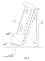
- FIG. 5 is a side view of an embodiment showing a holster with a device in a stand position.
- a holster for an electronic device may have one or more collapsible cushions that flex during installation and removal of the device from the holster.
- the cushions may have a large amount of flex such that the holster may hold multiple sizes of devices or devices with or without additional protective cases.
- the cushions may have a nonslip surface that helps hold the device securely while in the device.
- the cushions may be molded of thermoplastic elastomer, silicone, or other moldable material that may or may not contain silicone.
- Some embodiments may have the cushions extend outside of the holster cavity such that the portion of the cushions outside the cavity may act as nonslip feet when the holster is used in a stand position.
- FIG. 1 is a perspective view of an embodiment 100 showing a holster assembly 102 .
- FIG. 1 is not to scale.
- the holster assembly 102 is composed of a holster body 118 , cushions 104 and 106 , and a belt clip 110 .
- the holster body 118 may be a rigid component that has a cavity 108 into which a device may be stored.
- the device may be held on top by upper lips 112 and 114 , and held on the bottom by a lower trough 116 .
- the cushions may conform or deflect to provide a spring-like effect to hold a device in the holster.
- the cushions may be hollow on the inside and may be made from a silicone or thermoplastic elastomer material.
- FIG. 2 is a perspective view of an embodiment 200 showing the holster assembly 102 with a device 202 .
- FIG. 2 is not to scale.
- a device 202 is shown installed into the holster assembly 102 .
- the cushions 104 and 106 are shown.
- the device 202 may be a cellular telephone, music player, camera, or other device.
- the device 202 may be installed by first placing the device 202 against the cushions 104 and 106 , then pressing down to deflect the cushions 104 and 106 until the top of the device 202 fits underneath the upper lips 112 and 114 . The device may then be rotated into the holster cavity and released, allowing the cushions 104 and 106 to raise the device 202 against the upper lips 112 and 114 .
- the spring force of the cushions 104 and 106 may force the device 202 against the upper lips 112 and 114 , holding the device 202 in the holster in a secure fashion.
- the upper lips 112 and 114 may have a lip that contains the device 202 from falling forward (as viewed in the figure).
- the device 202 may be oriented in the lower trough 116 such that the device 202 is within the lower trough. In such an orientation, the lower trough may contain the device 202 within the holster, as the lower edge of the device 202 may be lower than the upper edge of the lower trough.
- the holster assembly 102 may be able to accommodate several different sized devices. Some embodiments may be able to securely hold a device 202 both with and without a protective case assembled onto the device 202 , or with a variety of protective cases.
- the holster assembly 102 is shown in the position where the upper lips 112 and 114 are at the top of the illustration.
- the holster assembly 102 may hold the device 202 in any orientation, including upside down from the illustration, rotated ninety degrees from the illustration, or any other configuration.
- the holster may be oriented such that the belt clip is facing upwards, such as if the belt clip 110 were attached to a sun visor in a user's car, for example.
- FIG. 3 is a perspective view of an embodiment 300 showing the holster assembly 102 from the rear.
- the holster assembly 102 is illustrated showing the belt clip 110 , upper lips 112 and 114 , and the cushion 104 .
- the belt clip 110 may be rotatable 360 degrees with respect to the holster body, allowing the user to configure the belt clip to mount on a variety of applications while holding the holster in a variety of orientations.
- FIGS. 4A, 4B, and 4C illustrate three views of a typical cushion.
- FIGS. 4A, 4B, and 4C are not to scale.
- FIG. 4A shows an embodiment 400 of a cushion from a lower perspective view.
- FIG. 4B shows an embodiment 402 of a cushion from an upper perspective view.
- FIG. 4C shows an embodiment 404 of a cross-sectional view of a cushion.
- the cushion 406 may be a hollow component that is manufactured from a flexible material.
- the cushion 406 may be molded from a thermoplastic elastomer, silicone, or some other flexible material.
- the cushion 406 may have a hollow area 412 .
- the hollow area 412 may collapse when crushed, but may return to the normal position, thus acting as a spring.
- the hollow area 412 may allow the cushion 406 to collapse to approximately 10-20% of its overall height.
- the cushion 406 may have a post 408 and tab 410 that may be used to attach the cushion 406 to a holster.
- the post 408 and tab 410 may be inserted into an opening or hole in the holster that corresponds with the shape of the post 408 .
- the tab 410 may protrude fully or partially from the hole in the holster.
- the thickness 422 may be the approximate thickness of the top and walls of the cushion 406 .
- the thickness 422 may be 0.010 in, 0.020 in, 0.050 in, 0.070 in, 0.100 in, or larger.
- the post 408 may have dimensions of a height 414 and width 416 .
- the width 416 may be the same as the thickness 422 .
- the width 416 may be various sizes, including 0.010 in, 0.020 in, 0.050 in, 0.070 in, 0.100 in, or larger, depending on the embodiment.
- the height 414 may be various sizes, including 0.010 in, 0.020 in, 0.050 in, 0.070 in, 0.100 in, or larger, depending on the embodiment.
- the height 414 may be the same thickness as the thickness of a holster body into which the cushion 406 may be attached.
- the tab 410 may have dimensions of a height 418 and width 420 .
- the height 418 may be selected to provide a nonslip foot for a holster when the holster is placed in a stand position.
- the height 418 may be the same as thickness 422 .
- the height 418 may be various sizes, including 0.010 in, 0.020 in, 0.050 in, 0.070 in, 0.100 in, or larger, depending on the embodiment.
- the tab width 420 may be larger than the post width 416 and may serve as a mechanism to keep the cushion 406 attached to the holster.
- the tab width 420 may be various sizes, including 0.010 in, 0.020 in, 0.050 in, 0.070 in, 0.100 in, or larger, depending on the embodiment.
- FIG. 5 is a side view of an embodiment 500 showing the holster assembly 102 in a stand position.
- FIG. 5 is not to scale.
- the holster assembly 102 is shown with a belt clip 110 in an open position and with the device 202 installed into the holster assembly 102 .
- the cushion 106 protrudes from the holster assembly 102 and may serve as a nonslip foot for the assembly.
Abstract
Description
Claims (19)
Priority Applications (1)
| Application Number | Priority Date | Filing Date | Title |
|---|---|---|---|
| US13/466,320 US9326587B2 (en) | 2012-05-08 | 2012-05-08 | Spring loaded holster for electronic device |
Applications Claiming Priority (1)
| Application Number | Priority Date | Filing Date | Title |
|---|---|---|---|
| US13/466,320 US9326587B2 (en) | 2012-05-08 | 2012-05-08 | Spring loaded holster for electronic device |
Publications (2)
| Publication Number | Publication Date |
|---|---|
| US20130299533A1 US20130299533A1 (en) | 2013-11-14 |
| US9326587B2 true US9326587B2 (en) | 2016-05-03 |
Family
ID=49547868
Family Applications (1)
| Application Number | Title | Priority Date | Filing Date |
|---|---|---|---|
| US13/466,320 Active 2032-11-09 US9326587B2 (en) | 2012-05-08 | 2012-05-08 | Spring loaded holster for electronic device |
Country Status (1)
| Country | Link |
|---|---|
| US (1) | US9326587B2 (en) |
Cited By (4)
| Publication number | Priority date | Publication date | Assignee | Title |
|---|---|---|---|---|
| US20160359515A1 (en) * | 2015-06-02 | 2016-12-08 | Chang Seob YOO | Cell phone fixing device of cell phone case |
| US20180099713A1 (en) * | 2016-10-06 | 2018-04-12 | David Oste | Bicycle Water Bottle Phone Holder |
| US10486615B1 (en) * | 2018-09-28 | 2019-11-26 | Toyoda Gosei Co., Ltd. | Storage holder |
| USD956167S1 (en) * | 2021-04-29 | 2022-06-28 | Ye Xu | Magnetic gun mount with trigger guard |
Families Citing this family (17)
| Publication number | Priority date | Publication date | Assignee | Title |
|---|---|---|---|---|
| FR3000575B1 (en) * | 2012-12-28 | 2015-02-13 | Faurecia Interieur Ind | HOLDING DEVICE FOR PORTABLE ELECTRONIC APPARATUS, INTERNAL STRUCTURE AND VEHICLE COMPRISING SUCH A DEVICE |
| US9271561B2 (en) * | 2013-02-08 | 2016-03-01 | David Chang | Apparatus for improving the interchangeability of portable electronic devices amongst various supports and related methods |
| US10004308B2 (en) * | 2015-01-13 | 2018-06-26 | Thomas Gerard Carpenter | Collar for portable device |
| USD765393S1 (en) * | 2015-01-27 | 2016-09-06 | Otter Products, Llc | Holster for a case for an electronic device |
| US9480319B2 (en) * | 2015-02-26 | 2016-11-01 | Cradl, Ltd. | Protective case for portable electronic device |
| USD791759S1 (en) * | 2015-06-22 | 2017-07-11 | Win2000 | Mobile phone cover |
| US10327538B2 (en) | 2016-08-26 | 2019-06-25 | Hugh D. Alexander | Method and apparatus for supporting and transporting personal portable devices using magnets |
| US11913595B1 (en) * | 2017-11-29 | 2024-02-27 | Frank Joseph Tortorella | Organizer and wall mount for organizer |
| USD869150S1 (en) * | 2017-12-21 | 2019-12-10 | Daniel Breitner | Mobile device mount |
| US11790706B2 (en) | 2019-10-30 | 2023-10-17 | Honda Motor Co., Ltd. | Methods and systems for calibrating vehicle sensors |
| USD961914S1 (en) | 2020-02-05 | 2022-08-30 | Magic Leap, Inc. | Holster for retractable device |
| USD986245S1 (en) | 2020-02-05 | 2023-05-16 | Magic Leap, Inc. | Holster with retractable device |
| USD975716S1 (en) | 2020-02-05 | 2023-01-17 | Magic Leap, Inc. | Holder for controller |
| USD933358S1 (en) * | 2020-02-05 | 2021-10-19 | Magic Leap, Inc. | Belt with device holders |
| USD998324S1 (en) | 2020-02-05 | 2023-09-12 | Magic Leap, Inc. | Belt assembly with holders and devices |
| USD961915S1 (en) | 2020-02-05 | 2022-08-30 | Magic Leap, Inc. | Holder with device |
| EP4188158A1 (en) * | 2020-07-27 | 2023-06-07 | Michael Watson | Portable personal hand sanitizer dispenser |
Citations (42)
| Publication number | Priority date | Publication date | Assignee | Title |
|---|---|---|---|---|
| US4420078A (en) | 1981-10-30 | 1983-12-13 | Norland Corporation | Carrying case for a cardiac pacer |
| US4842174A (en) | 1987-04-07 | 1989-06-27 | Sheppard Mark E | Flexible mount for mobile apparatus |
| USD359616S (en) * | 1994-04-01 | 1995-06-27 | Toyo Communication Equipment Co., Ltd. | Beeper holder |
| US5537678A (en) | 1993-04-05 | 1996-07-16 | Motorola, Inc. | Selective call receiver holster with integral display impact protection |
| US5555157A (en) | 1994-03-02 | 1996-09-10 | Apple Computer, Inc. | Enclosure for electronic apparatus having a cover catch member engageable with two different housing catch members |
| US5573164A (en) | 1994-01-11 | 1996-11-12 | Law; Carl F. | Interchangeably mounted accessories for vehicular use |
| US6029871A (en) | 1997-07-04 | 2000-02-29 | Samsung Electronic Co., Ltd. | Cradle device having rotating hinge in pager |
| US6176401B1 (en) | 1999-02-12 | 2001-01-23 | Motorola, Inc. | Holster for a portable communication device |
| US20010040109A1 (en) | 2000-05-10 | 2001-11-15 | Jud Yaski | Electronic device case |
| US6375009B1 (en) | 1998-02-10 | 2002-04-23 | Chung Kyun Lee | Bag with a shock absorbing unit |
| USD457308S1 (en) | 2001-04-02 | 2002-05-21 | Research In Motion Limited | Holster apparatus for use with a handheld device |
| US6491194B2 (en) * | 2001-01-29 | 2002-12-10 | Ernest Marvin | Cell phone holder for motor vehicles |
| US20030103624A1 (en) | 2001-12-05 | 2003-06-05 | Kingston Cell Taiwan Corp. | Slip casing for mobile phone |
| US20040099702A1 (en) | 2002-11-21 | 2004-05-27 | Conner William A. | Compartmented belt buckle for storing folded eyeglasses |
| US20040112143A1 (en) | 2001-11-19 | 2004-06-17 | Richardson Curtis R. | Protective membrane for touch screen device |
| US6752299B2 (en) | 2001-12-07 | 2004-06-22 | Medtronic Minimed, Inc. | Rotational holster for an electronic device |
| US20040262350A1 (en) | 2002-08-29 | 2004-12-30 | Batchelor Jeffrey Lyle | Portable electronic device detachable vehicle mounting and vehicle use systems |
| US20050189913A1 (en) | 2004-02-26 | 2005-09-01 | Vitanov Kamen B. | Electronic device including handheld electronic device with dual battery configuration, and associated method |
| USD510659S1 (en) | 2003-11-14 | 2005-10-18 | A. G. Findings & Mfg. Co., Inc. | Swivel belt clip for cellular telephone |
| US20060116183A1 (en) | 2004-12-01 | 2006-06-01 | Research In Motion Limited | Handheld wireless communication device and holder |
| US20060231713A1 (en) | 2005-04-15 | 2006-10-19 | Crain Stephen B | Mount system for handheld electrical device |
| US20070138041A1 (en) * | 2005-12-19 | 2007-06-21 | Welsh Robert P | Carrying Case |
| USD548960S1 (en) | 2006-01-04 | 2007-08-21 | A.G. Findings & Mfg. Co. | Belt or strap clip for cell phone or other personal electronic device |
| USD550450S1 (en) | 2006-11-07 | 2007-09-11 | Valor Communication, Inc. | One piece swivel belt clip for a cellular telephone |
| US7270255B2 (en) | 2000-07-07 | 2007-09-18 | Intelligent Designs 2000 Corp. | Carrying case with selectively adjustable stand |
| US20070261978A1 (en) | 2006-05-10 | 2007-11-15 | David Sanderson | Waterproof case for electronic devices |
| US20080156836A1 (en) | 2006-12-28 | 2008-07-03 | John Wadsworth | Rotating and pivoting belt clip that can be used as a stand |
| USD574819S1 (en) | 2007-06-25 | 2008-08-12 | Apple Inc. | Case |
| USD575056S1 (en) | 2008-02-19 | 2008-08-19 | Incase Designs Corporation | Portable electronic device case |
| USD594225S1 (en) | 2008-08-01 | 2009-06-16 | Research In Motion Limited | Hand-held electronic device holster |
| USD594224S1 (en) | 2008-08-01 | 2009-06-16 | Research In Motion Limited | Hand-held electronic device holster |
| US7562774B2 (en) | 2002-02-15 | 2009-07-21 | Arkray, Inc. | Kit holding adapter |
| USD596393S1 (en) | 2008-08-01 | 2009-07-21 | Research In Motion Limited | Hand-held electronic device holster |
| USD597089S1 (en) | 2008-08-21 | 2009-07-28 | Research In Motion Limited | Hand-held electronic device cover |
| USD603603S1 (en) | 2009-01-06 | 2009-11-10 | Powermat Usa, Llc | Case for an electronic device |
| USD606751S1 (en) | 2007-06-25 | 2009-12-29 | Apple Inc. | Cover |
| US20100006468A1 (en) * | 2008-07-11 | 2010-01-14 | Fruitshop International Co., Ltd. | Protection cover for portable product |
| US20100203931A1 (en) * | 2009-02-06 | 2010-08-12 | Bryan Lee Hynecek | One Piece Co-formed Exterior Hard Shell Case with an Elastomeric Liner for Mobile Electronic Devices |
| US20110000945A1 (en) * | 2009-07-06 | 2011-01-06 | Ryan Mongan | Electronic Device Holder |
| US20110073608A1 (en) * | 2009-09-30 | 2011-03-31 | Otter Products, Llc | Case |
| US20110155774A1 (en) * | 2009-12-31 | 2011-06-30 | Fellowes, Inc. | Dual function clip device for an electronic device having a screen |
| US20130118932A1 (en) * | 2011-11-11 | 2013-05-16 | Brittany Green | Decorative case |
-
2012
- 2012-05-08 US US13/466,320 patent/US9326587B2/en active Active
Patent Citations (45)
| Publication number | Priority date | Publication date | Assignee | Title |
|---|---|---|---|---|
| US4420078A (en) | 1981-10-30 | 1983-12-13 | Norland Corporation | Carrying case for a cardiac pacer |
| US4842174A (en) | 1987-04-07 | 1989-06-27 | Sheppard Mark E | Flexible mount for mobile apparatus |
| US5537678A (en) | 1993-04-05 | 1996-07-16 | Motorola, Inc. | Selective call receiver holster with integral display impact protection |
| US5573164A (en) | 1994-01-11 | 1996-11-12 | Law; Carl F. | Interchangeably mounted accessories for vehicular use |
| US5555157A (en) | 1994-03-02 | 1996-09-10 | Apple Computer, Inc. | Enclosure for electronic apparatus having a cover catch member engageable with two different housing catch members |
| USD359616S (en) * | 1994-04-01 | 1995-06-27 | Toyo Communication Equipment Co., Ltd. | Beeper holder |
| US6029871A (en) | 1997-07-04 | 2000-02-29 | Samsung Electronic Co., Ltd. | Cradle device having rotating hinge in pager |
| US6375009B1 (en) | 1998-02-10 | 2002-04-23 | Chung Kyun Lee | Bag with a shock absorbing unit |
| US6176401B1 (en) | 1999-02-12 | 2001-01-23 | Motorola, Inc. | Holster for a portable communication device |
| US20010040109A1 (en) | 2000-05-10 | 2001-11-15 | Jud Yaski | Electronic device case |
| US7270255B2 (en) | 2000-07-07 | 2007-09-18 | Intelligent Designs 2000 Corp. | Carrying case with selectively adjustable stand |
| US6491194B2 (en) * | 2001-01-29 | 2002-12-10 | Ernest Marvin | Cell phone holder for motor vehicles |
| USD457308S1 (en) | 2001-04-02 | 2002-05-21 | Research In Motion Limited | Holster apparatus for use with a handheld device |
| US20040112143A1 (en) | 2001-11-19 | 2004-06-17 | Richardson Curtis R. | Protective membrane for touch screen device |
| US20030103624A1 (en) | 2001-12-05 | 2003-06-05 | Kingston Cell Taiwan Corp. | Slip casing for mobile phone |
| US6752299B2 (en) | 2001-12-07 | 2004-06-22 | Medtronic Minimed, Inc. | Rotational holster for an electronic device |
| US7562774B2 (en) | 2002-02-15 | 2009-07-21 | Arkray, Inc. | Kit holding adapter |
| US20040262350A1 (en) | 2002-08-29 | 2004-12-30 | Batchelor Jeffrey Lyle | Portable electronic device detachable vehicle mounting and vehicle use systems |
| US20040099702A1 (en) | 2002-11-21 | 2004-05-27 | Conner William A. | Compartmented belt buckle for storing folded eyeglasses |
| USD510659S1 (en) | 2003-11-14 | 2005-10-18 | A. G. Findings & Mfg. Co., Inc. | Swivel belt clip for cellular telephone |
| US20050189913A1 (en) | 2004-02-26 | 2005-09-01 | Vitanov Kamen B. | Electronic device including handheld electronic device with dual battery configuration, and associated method |
| US20060116183A1 (en) | 2004-12-01 | 2006-06-01 | Research In Motion Limited | Handheld wireless communication device and holder |
| US20060231713A1 (en) | 2005-04-15 | 2006-10-19 | Crain Stephen B | Mount system for handheld electrical device |
| US20070138041A1 (en) * | 2005-12-19 | 2007-06-21 | Welsh Robert P | Carrying Case |
| USD564753S1 (en) | 2006-01-04 | 2008-03-25 | A.G. Findings & Mfg. Co. | Belt or strap clip for cell phone or other personal electronic device |
| USD548960S1 (en) | 2006-01-04 | 2007-08-21 | A.G. Findings & Mfg. Co. | Belt or strap clip for cell phone or other personal electronic device |
| US20070261978A1 (en) | 2006-05-10 | 2007-11-15 | David Sanderson | Waterproof case for electronic devices |
| USD550450S1 (en) | 2006-11-07 | 2007-09-11 | Valor Communication, Inc. | One piece swivel belt clip for a cellular telephone |
| US20080156836A1 (en) | 2006-12-28 | 2008-07-03 | John Wadsworth | Rotating and pivoting belt clip that can be used as a stand |
| US8070026B2 (en) | 2006-12-28 | 2011-12-06 | Belkin International, Inc. | Rotating and pivoting belt clip that can be used as a stand |
| USD574819S1 (en) | 2007-06-25 | 2008-08-12 | Apple Inc. | Case |
| USD606751S1 (en) | 2007-06-25 | 2009-12-29 | Apple Inc. | Cover |
| USD575056S1 (en) | 2008-02-19 | 2008-08-19 | Incase Designs Corporation | Portable electronic device case |
| USD582149S1 (en) | 2008-02-19 | 2008-12-09 | Incase Designs Corporation | Portable electronic device case |
| US20100006468A1 (en) * | 2008-07-11 | 2010-01-14 | Fruitshop International Co., Ltd. | Protection cover for portable product |
| USD596393S1 (en) | 2008-08-01 | 2009-07-21 | Research In Motion Limited | Hand-held electronic device holster |
| USD594224S1 (en) | 2008-08-01 | 2009-06-16 | Research In Motion Limited | Hand-held electronic device holster |
| USD594225S1 (en) | 2008-08-01 | 2009-06-16 | Research In Motion Limited | Hand-held electronic device holster |
| USD597089S1 (en) | 2008-08-21 | 2009-07-28 | Research In Motion Limited | Hand-held electronic device cover |
| USD603603S1 (en) | 2009-01-06 | 2009-11-10 | Powermat Usa, Llc | Case for an electronic device |
| US20100203931A1 (en) * | 2009-02-06 | 2010-08-12 | Bryan Lee Hynecek | One Piece Co-formed Exterior Hard Shell Case with an Elastomeric Liner for Mobile Electronic Devices |
| US20110000945A1 (en) * | 2009-07-06 | 2011-01-06 | Ryan Mongan | Electronic Device Holder |
| US20110073608A1 (en) * | 2009-09-30 | 2011-03-31 | Otter Products, Llc | Case |
| US20110155774A1 (en) * | 2009-12-31 | 2011-06-30 | Fellowes, Inc. | Dual function clip device for an electronic device having a screen |
| US20130118932A1 (en) * | 2011-11-11 | 2013-05-16 | Brittany Green | Decorative case |
Cited By (5)
| Publication number | Priority date | Publication date | Assignee | Title |
|---|---|---|---|---|
| US20160359515A1 (en) * | 2015-06-02 | 2016-12-08 | Chang Seob YOO | Cell phone fixing device of cell phone case |
| US20180099713A1 (en) * | 2016-10-06 | 2018-04-12 | David Oste | Bicycle Water Bottle Phone Holder |
| US10752309B2 (en) * | 2016-10-06 | 2020-08-25 | David Oste | Bicycle water bottle phone holder |
| US10486615B1 (en) * | 2018-09-28 | 2019-11-26 | Toyoda Gosei Co., Ltd. | Storage holder |
| USD956167S1 (en) * | 2021-04-29 | 2022-06-28 | Ye Xu | Magnetic gun mount with trigger guard |
Also Published As
| Publication number | Publication date |
|---|---|
| US20130299533A1 (en) | 2013-11-14 |
Similar Documents
| Publication | Publication Date | Title |
|---|---|---|
| US9326587B2 (en) | Spring loaded holster for electronic device | |
| US10750844B2 (en) | Protective case for use with device grip | |
| US9578940B2 (en) | Protective case for an electronic device | |
| US8887910B2 (en) | Low profile protective cover configurable as a stand | |
| US9027814B2 (en) | Holster accommodating different sized portable device cases | |
| US7757919B2 (en) | Carrying case with screen-protecting snap | |
| US9660682B2 (en) | Apparatus for holding an electronic device | |
| US10893131B2 (en) | Case for a mobile electronic device | |
| US11083263B2 (en) | Cellular device case having a built-in mount | |
| US6816740B2 (en) | Recharge apparatus for holding the rechargeable device | |
| US20160254835A1 (en) | Integrated screen and perimeter protector for an electronic device | |
| KR20160018306A (en) | Cover for portable electronic device | |
| US20130214018A1 (en) | Cellular Telephone Case | |
| KR200444219Y1 (en) | Mobile device case with sliding member | |
| KR101443538B1 (en) | Dual cover assembly for personal communication devices capable of inserting card means | |
| JP2004159683A (en) | Storage case for folding type cellular phone | |
| KR200476557Y1 (en) | Smart phon protection case having cushioning and sticking function | |
| KR200455103Y1 (en) | Combi case for cell phone | |
| KR20140001471U (en) | Pouch for mobile terminal | |
| USD501079S1 (en) | Hand held soft case for high tech electronic equipment | |
| KR20120000423U (en) | Case for personal potable device having supporting means | |
| KR200477794Y1 (en) | Mobile Phone Cover | |
| KR101491077B1 (en) | Case for mobile smart apparatus and method for manufacturing the same | |
| KR200496147Y1 (en) | Insert hook for case | |
| KR101745926B1 (en) | Battery receivable cap |
Legal Events
| Date | Code | Title | Description |
|---|---|---|---|
| AS | Assignment |
Owner name: OTTER PRODUCTS, LLC, COLORADO Free format text: ASSIGNMENT OF ASSIGNORS INTEREST;ASSIGNORS:GRONEWOLLER, PETER;MAGNESS, CAMERON;SIGNING DATES FROM 20120913 TO 20120914;REEL/FRAME:028966/0467 |
|
| AS | Assignment |
Owner name: WELLS FARGO BANK, NATIONAL ASSOCIATION, COLORADO Free format text: SECURITY AGREEMENT;ASSIGNOR:OTTER PRODUCTS, LLC;REEL/FRAME:029032/0434 Effective date: 20120730 |
|
| AS | Assignment |
Owner name: OTTER PRODUCTS, LLC, COLORADO Free format text: RELEASE OF SECURITY INTEREST IN INTELLECTUAL PROPERTY COLLATERAL AT REEL/FRAME NO. 29032/0434;ASSIGNOR:WELLS FARGO BANK, NATIONAL ASSOCIATION;REEL/FRAME:030427/0761 Effective date: 20130517 |
|
| AS | Assignment |
Owner name: WELLS FARGO BANK, NATIONAL ASSOCIATION, AS COLLATE Free format text: TERM LOAN IP SECURITY AGREEMENT;ASSIGNOR:OTTER PRODUCTS, LLC;REEL/FRAME:030571/0588 Effective date: 20130517 |
|
| AS | Assignment |
Owner name: WELLS FARGO BANK, NATIONAL ASSOCIATION, AS COLLATE Free format text: REVOLVING FACILITY IP SECURITY AGREEMENT;ASSIGNOR:OTTER PRODUCTS, LLC;REEL/FRAME:030724/0347 Effective date: 20130517 |
|
| AS | Assignment |
Owner name: OTTER PRODUCTS, LLC, COLORADO Free format text: RELEASE OF IP SECURITY AGREEMENTS IN REEL/FRAME NOS. 030571/0588 AND 030724/0347;ASSIGNOR:WELLS FARGO BANK, NATIONAL ASSOCIATION, AS COLLATERAL AGENT;REEL/FRAME:033082/0714 Effective date: 20140603 |
|
| AS | Assignment |
Owner name: BANK OF AMERICA, N.A., AS ADMINISTRATIVE AGENT, TE Free format text: SECURITY INTEREST;ASSIGNORS:OTTER PRODUCTS, LLC;TREEFROG DEVELOPMENTS, INC.;REEL/FRAME:033084/0596 Effective date: 20140603 |
|
| STCF | Information on status: patent grant |
Free format text: PATENTED CASE |
|
| AS | Assignment |
Owner name: BANK OF AMERICA, N.A., AS ADMINISTRATIVE AGENT, ILLINOIS Free format text: INTELLECTUAL PROPERTY SECURITY AGREEMENT;ASSIGNOR:OTTER PRODUCTS, LLC;REEL/FRAME:043681/0846 Effective date: 20170825 Owner name: BANK OF AMERICA, N.A., AS ADMINISTRATIVE AGENT, IL Free format text: INTELLECTUAL PROPERTY SECURITY AGREEMENT;ASSIGNOR:OTTER PRODUCTS, LLC;REEL/FRAME:043681/0846 Effective date: 20170825 |
|
| AS | Assignment |
Owner name: TREEFROG DEVELOPMENTS, INC., COLORADO Free format text: RELEASE OF SECURITY INTEREST IN INTELLECTUAL PROPERTY AT REEL/FRAME NO. 33084/0596;ASSIGNOR:BANK OF AMERICA, N.A., AS ADMINISTRATIVE AGENT;REEL/FRAME:043700/0028 Effective date: 20170825 Owner name: OTTER PRODUCTS, LLC, COLORADO Free format text: RELEASE OF SECURITY INTEREST IN INTELLECTUAL PROPERTY AT REEL/FRAME NO. 33084/0596;ASSIGNOR:BANK OF AMERICA, N.A., AS ADMINISTRATIVE AGENT;REEL/FRAME:043700/0028 Effective date: 20170825 |
|
| MAFP | Maintenance fee payment |
Free format text: PAYMENT OF MAINTENANCE FEE, 4TH YEAR, LARGE ENTITY (ORIGINAL EVENT CODE: M1551); ENTITY STATUS OF PATENT OWNER: LARGE ENTITY Year of fee payment: 4 |
|
| AS | Assignment |
Owner name: OTTER PRODUCTS, LLC, COLORADO Free format text: RELEASE OF SECURITY INTEREST IN INTELLECTUAL PROPERTY AT REEL/FRAME NO. 43681/0846;ASSIGNOR:BANK OF AMERICA, N.A., AS ADMINISTRATIVE AGENT;REEL/FRAME:051693/0484 Effective date: 20200124 Owner name: BANK OF AMERICA, N.A., AS ADMINISTRATIVE AGENT, ILLINOIS Free format text: INTELLECTUAL PROPERTY SECURITY AGREEMENT;ASSIGNOR:OTTER PRODUCTS, LLC;REEL/FRAME:051693/0592 Effective date: 20200124 |
|
| AS | Assignment |
Owner name: OTTER PRODUCTS, LLC, COLORADO Free format text: RELEASE OF SECURITY INTEREST IN INTELLECTUAL PROPERTY AT REEL/FRAME NO. 51693/0592;ASSIGNOR:BANK OF AMERICA, N.A., AS ADMINISTRATIVE AGENT;REEL/FRAME:059618/0308 Effective date: 20220330 |
|
| AS | Assignment |
Owner name: BANK OF AMERICA, N.A., AS ADMINISTRATIVE AGENT, NORTH CAROLINA Free format text: INTELLECTUAL PROPERTY SECURITY AGREEMENT;ASSIGNOR:OTTER PRODUCTS, LLC;REEL/FRAME:059554/0930 Effective date: 20220330 |
|
| MAFP | Maintenance fee payment |
Free format text: PAYMENT OF MAINTENANCE FEE, 8TH YEAR, LARGE ENTITY (ORIGINAL EVENT CODE: M1552); ENTITY STATUS OF PATENT OWNER: LARGE ENTITY Year of fee payment: 8 |