US8509865B1 - Mobile device with cushion devices - Google Patents

Mobile device with cushion devices Download PDF

Info

Publication number
US8509865B1
US8509865B1 US13/691,529 US201213691529A US8509865B1 US 8509865 B1 US8509865 B1 US 8509865B1 US 201213691529 A US201213691529 A US 201213691529A US 8509865 B1 US8509865 B1 US 8509865B1
Authority
US
United States
Prior art keywords
base wall
mobile device
side walls
cushion
case
Prior art date
Legal status (The legal status is an assumption and is not a legal conclusion. Google has not performed a legal analysis and makes no representation as to the accuracy of the status listed.)
Active
Application number
US13/691,529
Inventor
Charlie LaColla
Vivian Chou
Jason Pan
Shraddha Patel
Current Assignee (The listed assignees may be inaccurate. Google has not performed a legal analysis and makes no representation or warranty as to the accuracy of the list.)
Superior Communications Inc
Original Assignee
Superior Communications Inc
Priority date (The priority date is an assumption and is not a legal conclusion. Google has not performed a legal analysis and makes no representation as to the accuracy of the date listed.)
Filing date
Publication date
Application filed by Superior Communications Inc filed Critical Superior Communications Inc
Priority to US13/691,529 priority Critical patent/US8509865B1/en
Assigned to Superior Communications, Inc. reassignment Superior Communications, Inc. ASSIGNMENT OF ASSIGNORS INTEREST (SEE DOCUMENT FOR DETAILS). Assignors: PAN, JASON, Patel, Shraddha, CHOU, VIVIAN, Lacolla, Charlie
Priority to US13/964,852 priority patent/US8718730B1/en
Application granted granted Critical
Publication of US8509865B1 publication Critical patent/US8509865B1/en
Priority to US14/270,183 priority patent/US8909309B2/en
Assigned to BANK OF AMERICA, N.A. reassignment BANK OF AMERICA, N.A. SECURITY INTEREST (SEE DOCUMENT FOR DETAILS). Assignors: Superior Communications, Inc.
Assigned to BANK OF AMERICA, N.A., AS AGENT reassignment BANK OF AMERICA, N.A., AS AGENT SECURITY INTEREST (SEE DOCUMENT FOR DETAILS). Assignors: Superior Communications, Inc.
Active legal-status Critical Current
Anticipated expiration legal-status Critical

Links

Images

Classifications

    • HELECTRICITY
    • H04ELECTRIC COMMUNICATION TECHNIQUE
    • H04BTRANSMISSION
    • H04B1/00Details of transmission systems, not covered by a single one of groups H04B3/00 - H04B13/00; Details of transmission systems not characterised by the medium used for transmission
    • H04B1/38Transceivers, i.e. devices in which transmitter and receiver form a structural unit and in which at least one part is used for functions of transmitting and receiving
    • H04B1/3827Portable transceivers
    • H04B1/3888Arrangements for carrying or protecting transceivers
    • HELECTRICITY
    • H04ELECTRIC COMMUNICATION TECHNIQUE
    • H04MTELEPHONIC COMMUNICATION
    • H04M1/00Substation equipment, e.g. for use by subscribers
    • H04M1/02Constructional features of telephone sets
    • H04M1/04Supports for telephone transmitters or receivers
    • AHUMAN NECESSITIES
    • A45HAND OR TRAVELLING ARTICLES
    • A45CPURSES; LUGGAGE; HAND CARRIED BAGS
    • A45C13/00Details; Accessories
    • A45C13/36Reinforcements for edges, corners, or other parts
    • AHUMAN NECESSITIES
    • A45HAND OR TRAVELLING ARTICLES
    • A45CPURSES; LUGGAGE; HAND CARRIED BAGS
    • A45C11/00Receptacles for purposes not provided for in groups A45C1/00-A45C9/00
    • A45C2011/002Receptacles for purposes not provided for in groups A45C1/00-A45C9/00 for portable handheld communication devices, e.g. mobile phone, pager, beeper, PDA, smart phone
    • HELECTRICITY
    • H04ELECTRIC COMMUNICATION TECHNIQUE
    • H04MTELEPHONIC COMMUNICATION
    • H04M1/00Substation equipment, e.g. for use by subscribers
    • H04M1/02Constructional features of telephone sets
    • H04M1/18Telephone sets specially adapted for use in ships, mines, or other places exposed to adverse environment
    • H04M1/185Improving the rigidity of the casing or resistance to shocks

Definitions

  • the present disclosure relates to protective cases for mobile devices.
  • Mobile devices in the form of phones, computers, digital assistants, and hand held devices have become commonplace in society.
  • Cellular phones, for example, are now carried by individuals at work, at home, at play, and in a variety of other environments.
  • the increased range of wireless communication coverage enhances the variety of environments in which wireless-enabled mobile devices may be used. It may not be unusual to see a mobile device used while an individual is at the beach, at the mall, near a river, walking over a rocky surface, or hiking up a mountain.
  • Cases have been developed that protect mobile devices from dirt and scratches that may accumulate from normal use.
  • the cases may comprise a shell or other covering that extends over the mobile device so that dirt does not enter crevices of the mobile device, or so the outer finish of the device is not scratched.
  • the rising costs of mobile devices may make it be worthwhile for an individual to invest in a case that protects the mobile device from dirt or scratches.
  • the case includes a base wall having an inner surface and an outer surface and that is configured to cover a surface of the mobile device.
  • the case includes a plurality of side walls each having an inner surface and an outer surface and that is configured to cover a side surface of the mobile device.
  • a plurality of side walls join to form at least four corners of the case.
  • Each of the plurality of side walls join to an adjacent one of the side walls to form the at least four corners.
  • An aperture is positioned at each corner and extends from the inner surface of at least one of the side walls to the outer surface of the at least one of the side walls.
  • the plurality of side walls each have an inner surface and an outer surface and are configured to cover a side surface of the mobile device.
  • the plurality of side walls extend from the base wall such that the inner surfaces of the plurality of side walls and the inner surface of the base wall form a recess configured to receive the mobile device.
  • the inner surfaces of the plurality of side walls and inner surface of the base wall face towards the mobile device when the mobile device is received in the recess.
  • the outer surfaces of the plurality of side walls and the outer surface of the base wall face away from the mobile device when the mobile device is received in the recess.
  • the plurality of side walls have a plurality of apertures.
  • FIG. 6 illustrates a bottom view of a case for a mobile device, according to an embodiment of the present disclosure.
  • FIG. 8 illustrates a front side perspective view of a case for a mobile device, according to an embodiment of the present disclosure.
  • FIG. 9 illustrates a front side perspective view of a case for a mobile device, according to an embodiment of the present disclosure.
  • FIG. 10 illustrates a front side perspective view of a case for a mobile device, according to an embodiment of the present disclosure.
  • FIG. 11 illustrates a rear side perspective view of a case for a mobile device, according to an embodiment of the present disclosure.
  • FIG. 15 illustrates a perspective view of a corner of a case, according to an embodiment of the present disclosure.
  • FIG. 16 illustrates a cross sectional view of a corner of a case, according to an embodiment of the present disclosure.
  • FIG. 18 illustrates a cross sectional view taken along a length of a case, according to an embodiment of the present disclosure.
  • FIG. 19 illustrates a front perspective view of a case with a mobile device received by a recess of the case, according to an embodiment of the present disclosure.
  • the base wall 12 includes an inner surface 28 and an outer surface 30 (shown in FIG. 2 ).
  • the inner surface 28 faces towards the mobile device when the mobile device is received in the recess 16 .
  • the outer surface 30 faces away from the mobile device when the mobile device is received in the recess 16 .
  • the base wall 12 may extend outward from the central portion 24 of the case 10 to form a substantially rectangular shape.
  • the rectangular shape may be formed to match the shape of a rectangular mobile device that is contained within the case 10 .
  • the outer portions 26 of the case 10 terminate at the outer portions of the mobile device that is contained therein.
  • the shape of the base wall 12 may be configured in any shape as desired based on the shape of the mobile device to be retained.
  • the base wall 12 may have a curved shape.
  • the curvature of the base wall 12 may match a shape of the portion of the mobile device to be retained.
  • the base wall 12 may be dimensioned to match dimensions of the mobile device as desired, for example, the base wall 12 may be dimensioned to have a square, or oblong shape to match the dimensions of a mobile device as desired.
  • the base wall 12 may not match the shape of the mobile device, but may have any shape that still allows the base wall 12 to cover a surface of the mobile device.
  • the interior layer 32 may be made of a pliable material that is sufficiently rigid to form a portion of the case 10 , yet offers an amount of shock resistance for the mobile device contained therein.
  • the interior layer 32 may comprise an elastomeric material, for example an elastomeric polymer or the like configured to provide shock resistance for the mobile device.
  • the interior layer 32 may be made from an elastomeric thermoplastic polyurethane.
  • the exterior layer 34 (shown in FIG. 2 ) may be made of a material that is less pliable than the material of the interior layer 32 , and may have a greater hardness than the material of the interior layer 32 .
  • the material of the exterior layer 34 may offer greater penetration resistance for the case 10 than the material forming the interior layer 32 .
  • the exterior layer 34 may comprise a hard plastic, for example, polycarbonate or the like.
  • the interior layer 32 and exterior layer 34 may be made of identical materials, or materials having similar properties, or may be made of any combination of materials as desired.
  • Each of the side walls 14 includes a respective inner surface 36 a , 36 b , 36 c , 36 d (referred to collectively as 36 ) and an outer surface 38 a , 38 b , 38 c , 38 d (referred to collectively as 38 ).
  • Each of the inner surfaces 36 face towards the mobile device when it is received in the recess 16 .
  • Each of the outer surfaces 38 face away from the mobile device when it is received in the recess 16 .
  • the side walls 14 may extend upward from the base wall 12 to a distance that that extends over the side of the mobile device or matches the height of the side of the mobile device. In one embodiment, any of the side walls 14 may extend upward from the base wall 12 such that only a part of the side of the mobile device is covered.
  • Each of the side walls 14 may be formed of a continuous piece of material or may be formed of a material that includes apertures or cut-outs through any of the respective side walls 14 .
  • a portion of the interior layer 32 may extend from the base wall 12 to form a portion of any of the side walls 14 as desired.
  • the portion of the interior layer 32 forming a part of the side walls 14 may be integral with the interior layer 32 of the base wall 12 .
  • the pliability of the interior layer 32 as utilized by the side walls 14 may allow the side walls 14 to more easily bend to allow the mobile device to be more easily inserted into the recess 16 .
  • a portion of the exterior layer 34 may extend from the base wall 12 to form a portion of any of the side walls 14 as desired.
  • the portion of the exterior layer 34 forming a part of the side walls 14 may be integral with the exterior layer 34 of the base wall 12 .
  • the rigidity of the exterior layer 34 as utilized by the side walls 14 may provide greater support for the side walls 14 to maintain their shape when the mobile device is received by the recess 16 .
  • any of the side walls 14 may be formed from a single piece of material.
  • any of the side walls 14 may be formed from multiple pieces of material.
  • any of the side walls 14 may be formed from material that is not integral with a portion of the base wall 12 .
  • the side walls 14 may extend from the base wall 12 in a direction that is substantially perpendicular, or ninety degrees from a direction the base wall 12 extends in.
  • the base wall 12 has a substantially flat shape, with each of the side walls 14 similarly having a flat shape that extends in a direction substantially perpendicular to the plane of the base wall 12 .
  • any of the side walls 14 may have a curved shape, yet may have a portion that extends in a direction substantially perpendicular to a direction that a portion of the base wall 12 extends in.
  • any of the side walls 14 may have any shape as desired relative to the base wall 12 such that a side surface of the mobile device is covered.
  • the side walls 14 in combination may form a rim around the base wall 12 that allow side surfaces of the mobile device to be covered.
  • the rim may extend around the sides surfaces of the mobile device to form corners that match the position of corners of the mobile device.
  • the side walls 14 may extend relative to each other in a direction that is substantially perpendicular or ninety (90) degrees from a direction that an adjacent one of the side walls 14 extends in.
  • the side walls 14 may form a substantially rectangular, or box-like, shape that covers side surfaces of the mobile device.
  • any of the side walls 14 may have a curved shape, yet may have a portion that extends in a direction substantially perpendicular to a direction that an adjacent one of the side walls 14 extends in.
  • the combination of the inner surface 28 of the base wall 12 and the inner surfaces 36 of the side walls 14 form the recess 16 for receiving the mobile device.
  • the recess 16 is bounded on its sides by the side walls 14 .
  • the recess 16 is bounded at its bottom by the base wall 12 .
  • the top of the recess opens into an aperture 40 that the mobile device passes through to be received by the recess 16 .
  • four side walls 14 bound the four sides of the recess 16 .
  • any number of side walls 14 may be utilized to bound the recess 16 as desired.
  • a recess 16 may be formed through use of two side walls extending at a distance from the base wall 12 , with the distance defining the indentation or cavity that the mobile device is received in.
  • the cushion devices 18 extend through respective apertures 58 a , 58 b , 58 c , 58 d (referred to collectively as 58 ) (identified in FIG. 12 ) positioned in the side walls 14 that extend from the inner surfaces 36 of the side walls 14 to the outer surfaces 38 of the side walls 14 .
  • the apertures may be positioned at corners 42 a , 42 b , 42 c , 42 d (referred to collectively as 42 ) of the case 10 .
  • Side walls 14 adjacent to one another join at the respective corners 42 , and form an angle relative to each other.
  • the cushion devices 18 are configured to cushion the mobile device from a force exerted upon the case 10 .
  • the cushion devices 18 may be formed from shock absorbing material, which may be elastic. Such materials may include an elastomeric material such as rubber, or the like. In one embodiment, the cushion devices 18 may be formed of material having a durometer between approximately 30-60.
  • the cushion devices 18 may be made of a material that has greater resistance to shock than the materials forming the base wall 12 and the side walls 14 .
  • the cushion devices 18 may be structured to substantially absorb a force, or part of a force, applied to the case 10 such that the entirety of the force is not transmitted directly to the mobile device. The cushion devices 18 may deform upon the force being applied, to absorb energy of the force.
  • the cushion devices 18 may serve to reduce the possibility of damage to the mobile device if the case 10 is dropped or hit by an object.
  • the cushion devices 18 may additionally serve to reduce force that is transmitted to the remainder of the case 10 .
  • the cushion devices 18 may reduce force applied to the base layer 12 or side walls 14 forming the housing or shell of the case 10 .
  • the cushion devices 18 may be removable from the apertures such that the cushion devices 18 are not permanently joined to the remainder of the case 10 .
  • the removable feature of the cushion devices 18 may serve to reduce the force that is transmitted to the remainder of the case 10 .
  • the cushion devices 18 may lack a chemical or electrical bond to the remainder of the case 10 that reduces the strength of the force transmitted thereto.
  • the cushion devices 18 may be removable to allow different cushion devices 18 , having different properties (e.g., hardness, durability, elasticity, and the like) to be inserted and placed in the apertures.
  • the removable feature additionally may allow the cushion devices 18 to be more easily made of a different material than the base wall 12 or the side wall 14 of the case 10 .
  • the cushion devices 18 may be formed separate from the base wall 12 and side wall and then inserted manually into the apertures.
  • the manual insertion process may reduce manufacturing expense, by reducing the need for a separate molding step to form the cushion devices 20 in place.
  • the manual insertion process may allow a distributor to more easily select different cushion devices with different properties (e.g., hardness, durability, elasticity, and the like) to be inserted and placed in the apertures based on a particular shape or style of a desired mobile device.
  • the case 10 may be fitted for a particular shape or style of mobile device after the factory manufacturing process takes place, for example, a salesperson may fit the case 10 in-store, or at the point of sale, for a particular mobile device.
  • the cushion devices may be removable, in one embodiment, they may not be intended for the end-consumer to remove the cushion device, because the mobile device will not properly fit in the case 10 with the cushion devices removed.
  • an end-consumer may damage a cushion device if they attempt to remove the cushion device from the case 10 .
  • the cushion devices 18 may be permanently fixed to the side walls 14 of the case.
  • the cushion devices 18 may be positioned at any location desired along the side walls 14 to reduce a force from being transmitted to the mobile device.
  • the cushion devices 18 are positioned at the corners 42 of the case 10 to stabilize the mobile device at its vertices.
  • a force applied directly to the case corners 42 will likely be more focused because it is not distributed along a long surface of the case 10 , such as along a length of one of the side walls 14 or the length of the outer surface 30 of the base wall 12 (shown in FIG. 2 ).
  • the cushion devices 18 at the corners may dissipate this focused force and reduce its transmission to the mobile device.
  • the number of cushion devices 18 utilized may also be varied. Preferably, in an embodiment in which the cushion devices 18 are positioned at the corners 42 of the case, a cushion device 18 will be positioned at each corner. For an embodiment in which the mobile device has four corners, then four cushion devices 18 may be utilized. However, shock absorption may still be provided if a cushion device 18 is not positioned at each corner. In one embodiment, only one cushion device 18 may be utilized at one corner, to provide some shock absorption for the mobile device. In an embodiment in which cushion devices 18 are positioned at multiple locations along the side walls 14 , any number of cushion devices 18 may be utilized as desired to provide shock absorption. Cushion devices 18 may extend through apertures positioned in the middle of each of the side walls 14 , for example.
  • the cushion device 20 positioned upon the base wall 12 may be configured to cushion the mobile device from a force exerted upon the case 10 , similar to the cushion devices 18 extending through the side walls 14 .
  • the cushion device 20 positioned upon the base wall 12 may be referred to as a base wall cushion device 20 and the cushion devices 18 extending through the side walls 14 may be referred to as side wall cushion devices 18 .
  • the base wall cushion device 20 may be formed from shock absorbing material, which may be elastic. Such materials may include an elastomeric material such as rubber, or the like.
  • the cushion devices 18 may be formed of material having a durometer between approximately 30-60.
  • the base wall cushion device 20 may be made of a material that has greater resistance to shock than the materials forming the base wall 12 and the side walls 14 .
  • the base wall cushion device 20 may be structured to substantially absorb a force, or part of a force, applied to the case 10 such that the entirety of the force is not transmitted directly to the mobile device.
  • the base wall cushion device 20 may deform upon the force being applied, to absorb energy provided by the force.
  • the base wall cushion device 20 may serve to reduce the possibility of damage to the mobile device if the case 10 is dropped or hit by an object.
  • the base wall cushion device 20 may not be formed integrally with the base wall 12 .
  • the base wall cushion device 20 may be formed separate from the base wall 12 to allow the cushion device 20 to be made of a different material than the base wall 12 .
  • the base wall cushion device 20 may be formed separate and fixed to the base wall 12 through an adhesive, or may be mechanically joined to the base wall 12 .
  • the base wall cushion device 20 may be formed integral with the base wall 12 through a molding process.
  • the base wall cushion device 20 is preferably positioned at a central location along the base wall 12 , as shown in FIG. 1 . However, the base wall cushion device 20 may be positioned at variable locations as desired. Any number of additional base wall cushion devices 20 may be utilized, for example, sufficient numbers of cushion devices 20 may be utilized to substantially entirely cover the base wall 12 .
  • the base wall cushion device 20 is preferably shaped to have a surface area that contacts a surface of the mobile device at multiple locations. Contact at multiple locations allows any force transmitted through the cushion device 20 to be distributed to the multiple locations on the surface of the mobile device.
  • the base wall cushion device 20 preferably has a substantially flattened or planar contact surface that contacts the surface of the mobile device and distributes the reduced force substantially evenly along the contact surface.
  • the base wall cushion device 20 may have any outline or dimensional shape, as desired, including a rectangular shape as shown in FIG. 1 , or a diamond, or circular shape, as desired.
  • the aperture 22 is positioned on the base wall 12 and extends from the inner surface 28 to the outer surface 30 of the base wall 12 .
  • the aperture 22 is configured to allow an element of the mobile device to be utilized through the case 10 .
  • the aperture 22 shown in FIG. 1 corresponds to a camera used by the mobile device.
  • the base wall 12 and side walls 14 may include any number of apertures or cut outs as desired, to correspond to an element of the mobile device or to otherwise allow access to the mobile device through the case 10 . Apertures or cut outs may be positioned in the base wall 12 and any of the side walls 14 to reduce the weight of the case 10 , for example.
  • FIG. 2 illustrates a rear view of the case 10 showing the outer surface 30 of the base wall 12 .
  • the exterior layer 34 of the base wall 12 forms a portion of the outer surface 30 of the base wall 12 .
  • the interior layer 32 of the base wall 12 may pass through a portion of the exterior layer 34 to form a portion of the outer surface 30 of the base wall 12 .
  • the interior layer 32 extends through the exterior layer 34 at the corners 42 of the case 10 .
  • the interior layer 32 may not extend through the exterior layer 34 .
  • the interior layer 32 may pass through any portion of the exterior layer 34 as desired.
  • the proportionate amount of interior layer 32 that extends through the exterior layer 34 may be determined based on the total amount of pliability or rigidity desired for the case 10 .
  • FIG. 3 illustrates a side view of the case 10 showing the outer surface 38 d of one of the side walls 14 .
  • the exterior layer 34 extends upward from the base wall 12 (shown in FIG. 2 ) to form a portion of the outer surface 38 d of the side wall 14 d .
  • the interior layer 32 of the base wall 12 extends upward from the base wall 12 to form a portion of the outer surface 38 d of the side wall 14 d .
  • the interior layer 32 may pass through a portion of the exterior layer 34 .
  • the interior layer 32 may form grips 44 on the outer surface 38 d of the side wall 14 d .
  • the grips 44 are configured to reduce the possibility that the case 10 slips from a user's hand while the case 10 is being gripped.
  • the interior layer 32 may also form depressible portions 46 on the outer surface 38 d of the side wall 14 d .
  • the depressible portions 46 may be used to transmit a force to elements on the mobile device, including buttons, for example.
  • An aperture 48 may be positioned on the side wall 14 d to allow access to the mobile device through the case 10 .
  • the aperture 48 shown in FIG. 3 allows access to a switch on the mobile device.
  • FIG. 4 illustrates a side view of the case 10 showing the outer surface 38 b of one of the side walls 14 .
  • the exterior layer 34 extends upward from the base wall 12 (shown in FIG. 2 ) to form a portion of the outer surface 38 b of the side wall 14 b .
  • the interior layer 32 of the base wall 12 extends upward from the base wall 12 to form a portion of the outer surface 38 b of the side wall 14 b .
  • the interior layer 32 may pass through a portion of the exterior layer 34 .
  • the interior layer 32 may form grips 50 on the outer surface 38 b of the side wall 14 b , serving a similar function as the grips 44 shown in FIG. 3 .
  • FIG. 5 illustrates a top view of the case 10 showing the outer surface 38 a of one of the side walls 14 .
  • the exterior layer 34 extends upward from the base wall 12 (shown in FIG. 2 ) to form a portion of the outer surface 38 a of the side wall 14 a .
  • the interior layer 32 of the base wall 12 extends upward from the base wall 12 to form a portion of the outer surface 38 a of the side wall 14 a .
  • the interior layer 32 may pass through a portion of the exterior layer 34 .
  • the interior layer 32 may form a depressible portion 52 on the outer surface 38 a of the side wall 14 a , that serves a similar function as the depressible portion 46 shown in FIG. 3 .
  • FIG. 6 illustrates a bottom view of the case 10 showing the outer surface 38 c of one of the side walls 14 .
  • the exterior layer 34 extends upward from the base wall 12 (shown in FIG. 2 ) to form a portion of the outer surface 38 c of the side wall 14 c .
  • the interior layer 32 of the base wall 12 extends upward from the base wall 12 to form a portion of the outer surface 38 o of the side wall 14 c .
  • the interior layer 32 may pass through a portion of the exterior layer 34 .
  • An aperture 54 may be positioned on the side wall 14 c to allow access to the mobile device through the case 10 .
  • the aperture 54 shown in FIG. 6 allows access to electrical connectors on the mobile device.
  • the interior layer 32 may not extend through the exterior layer 34 of the side walls 14 shown in FIGS. 3-6 . In one embodiment, the interior layer 32 may pass through any portion of the exterior layer 34 of the side walls 14 as desired. In an embodiment in which the interior layer 32 is a pliable material, and the exterior layer 34 is a rigid material, the proportionate amount of interior layer 32 that extends through the exterior layer 34 may be determined based on the total amount of pliability or rigidity desired for the side walls 14 of the case 10 . A rigid exterior layer 34 extending over the side walls 14 may form a rigid shell around the interior layer 32 .
  • a lip 56 extends from the side walls 14 towards the interior of the case 10 .
  • the lip 56 is positioned at an end of the side walls 14 that is opposite an end of each of the side walls 14 fixed to the base wall 12 .
  • the lip 56 is configured to retain the mobile device within the recess 16 upon the mobile device being inserted into the recess 16 .
  • the lip 56 may extend continuously around the side walls 14 of the case 10 or may extend over only a portion of at least one of the side walls 14 .
  • the lip 56 may be formed from the material forming the interior layer 32 of the base wall 12 .
  • the lip 56 may define the bounds of the aperture 40 that the mobile device passes through to be received by the recess 16 .
  • each of the side wall cushion devices 18 extends into the interior of the case 10 .
  • the portion of the side wall cushion devices 18 that extends into the interior of the case 10 is configured to contact the mobile device to cushion the mobile device from a force.
  • FIG. 8 illustrates a front side perspective view of the case 10 .
  • the interior surfaces 36 c , 36 d of two of the side walls 14 are shown.
  • the interior layer 32 of the base wall 12 extends upward from the base wall 12 to form a portion of the interior surfaces 36 c , 36 d of the side walls 14 c , 14 d.
  • FIG. 9 illustrates a front side perspective view of the case 10 .
  • the interior surfaces 36 a , 36 b of two of the side walls 14 are shown.
  • the interior layer 32 of the base wall 12 extends upward from the base wall 12 to form a portion of the interior surfaces 36 a , 36 b of the side walls 14 a , 14 b.
  • FIG. 10 illustrates a front side perspective view of the case 10 .
  • the interior surfaces 36 a , 36 d of two of the side walls 14 are shown.
  • the interior layer 32 of the base wall 12 extends upward from the base wall 12 to form a portion of the interior surfaces 36 a , 36 d of the side walls 14 a , 14 d.
  • FIG. 11 illustrates a rear side perspective view of the case 10 .
  • FIG. 13 illustrates a front perspective view of one of the side wall cushion devices 18 .
  • Each of the side wall cushion devices 18 shown in FIG. 12 may be configured similarly as the cushion device 18 a shown in FIG. 13 .
  • any or all of the cushion devices 18 may be configured differently, as desired.
  • the side wall cushion device 18 a includes an inner flange 60 and an outer flange 62 connected by a neck 64 .
  • the inner flange 60 is a portion of the cushion device 18 a positioned interior of the side walls 14 when the cushion device 18 a is inserted through a respective aperture 58 a (shown in FIG. 12 ).
  • the outer flange 62 is a portion of the cushion device 18 a positioned exterior of the side walls 14 when the cushion device 18 a is inserted through a respective aperture 58 a .
  • the outer flange 62 and inner flange 60 may secure the cushion device 18 a within the aperture 58 a .
  • the neck 64 is positioned within the respective aperture 58 a when the cushion device 18 a extends through the aperture 58 a.
  • the outer flange 62 is preferably sized larger than the size of the respective aperture 58 a (shown in FIG. 12 ) to prevent the cushion device 18 a from becoming dislodged from the aperture 58 a .
  • the outer flange 62 is preferably sized to have an outer surface area that is large, and larger than the area of the aperture 58 a , to provide material that receives and absorbs force applied to the outer flange 62 .
  • the outer flange 62 may have a shape that contours to the shape of the respective outer surfaces 38 a , 38 b of the side walls 14 a , 14 b (shown in FIGS. 4 and 5 ).
  • the outer flange 62 may have a curved or angled shape when the cushion device 18 a is positioned at the corner of the case 10 .
  • the outer flange 62 may have sufficient length to cover the respective outer surfaces 38 a , 38 b of side walls 14 a , 14 b at the corner of the case 10 , to absorb force applied to the corner of the case 10 .
  • the outer flange 62 has an oblong or oval shape. In other embodiments, the outer flange 62 may have any shape that retains the cushion device 18 a within the respective aperture 58 a as desired.
  • the inner flange 60 is preferably sized larger than the size of the respective aperture 58 a (shown in FIG. 12 ) to prevent the cushion device 18 a from becoming dislodged from the aperture 58 a .
  • the inner flange 60 is preferably sized to have an interior surface area that is large, and larger than the area of the aperture 58 a , to provide material that absorbs force applied to the outer flange 62 and preferably does not deliver the entirety of the force to the mobile device.
  • the inner flange 60 may include a horizontal support 66 , a stabilizer 68 , and a vertical support 70 .
  • the vertical support 70 may be contoured to form a corner recess 72 .
  • the horizontal support 66 may comprise a flattened protrusion extending outward from the inner flange 60 .
  • the horizontal support 66 may extend such that a portion of the mobile device may rest upon the horizontal support 66 .
  • the horizontal support 66 may have a thickness, or distance, from the base wall 12 (shown in FIG. 1 ) such that the mobile device does not contact the base wall 12 when resting upon the horizontal support 66 .
  • the horizontal support 66 may reduce the possibility that force is directly transmitted from the base wall 12 to the mobile device through contact therebetween.
  • the stabilizer 68 may comprise a ridge that extends from the inner flange 60 and contacts a portion of the base wall 12 (shown in FIG. 1 ). The stabilizer 68 may contact the base wall 12 to align the inner flange 60 in position when it is inserted through the respective aperture 58 a (shown in FIG. 12 ).
  • the vertical support 70 may comprise a flattened wall that fits against and covers the respective interior surfaces 36 a , 36 b of the side walls 14 a , 14 b (shown in FIG. 9 ). When the cushion device 18 a is inserted into the respective aperture 58 a (shown in FIG. 12 ), the vertical support 70 may extend such that a portion of the mobile device may press against the vertical support 70 .
  • the vertical support 70 may have a thickness, or distance, from the respective side walls 14 a , 14 b (shown in FIG. 9 ) such that the mobile device does not contact the respective side walls 14 a , 14 b when pressing against the vertical support 70 .
  • the vertical support 70 may reduce the possibility that force is directly transmitted from one of the side walls 14 to the mobile device through contact therebetween.
  • the vertical support 70 may have a height, or distance, such that an entire height of the respective inner surfaces 36 a , 36 b of the side walls 14 a , 14 b below the lip 56 are filled with the vertical support 70 .
  • the corner recess 72 is shaped to receive a corner of the mobile device.
  • the vertical support 70 may be curved to extend around the corner of the mobile device to provide cushioning support for the corner in directions towards both of the adjacent side walls 14 a , 14 b (shown in FIG. 9 ).
  • the inner flange 60 may have any shape as desired to provide cushioning for the mobile device when retained by the case.
  • the vertical support 70 may not be contoured to include a corner recess 72 .
  • FIG. 14 illustrates a rear perspective view of the side wall cushion device 18 a showing the outer flange 62 .
  • the outer flange 62 and/or inner flange 60 may be configured such that the outer flange 62 and/or inner flange 60 must deform to allow the cushion device 18 to pass through the respective aperture 58 a , to allow the cushion device 18 a to be retained within the aperture 58 a , or removed from the aperture 58 a.
  • FIG. 15 illustrates a detail view of one of the corners 42 of the case 10 , with the respective side wall cushion device 18 a removed.
  • Each of the corners 42 shown in FIGS. 7-10 may be configured similarly as the corner 42 a shown in FIG. 15 . In one embodiment, any or all of the corners 42 may be configured differently, as desired.
  • Two of the side walls 14 a , 14 b join at the corner 42 a , and the aperture 58 a extends through a portion of each of the side walls 14 a , 14 b .
  • Each of the side walls 14 a , 14 b join with each other at approximately a midpoint of the aperture 58 a .
  • the side walls 14 a , 14 b may be mechanically joined at the aperture 58 a or may be integrally formed such that they are joined with one another at the aperture 58 a .
  • the ends of the side walls 14 a , 14 b entirely encircle the cushion device 18 a when it is inserted through the aperture 58 a .
  • the aperture 58 a may be positioned at the corner 42 a , but may be offset from the position shown in FIG. 15 , such that the aperture 58 a only extends through one of the two side walls 14 a , 14 b.
  • a side wall recess 74 is cut into the side walls 14 a , 14 b at the corner 42 a .
  • the side wall recess 74 is preferably shaped to securely receive and retain the side wall cushion device 18 a when it is passed through the aperture 58 a.
  • FIG. 16 illustrates a cross sectional view of one of the corners 42 a of the case 10 , with the respective side wall cushion device 18 a extending through the aperture 58 a .
  • Each of the corners 42 shown in FIGS. 7-10 may be configured similarly as the corner 42 a shown in FIG. 16 . In one embodiment, any or all of the corners 42 may be configured differently, as desired.
  • the cushion device 18 a fills the side wall recess 74 shown in FIG. 15 .
  • the outer flange 62 is positioned exterior to the respective side walls 14 a , 14 b (shown in FIG. 15 ).
  • the inner flange 60 is positioned interior to the respective side walls 14 a , 14 b .
  • the stabilizer 68 abuts the interior layer 32 and the exterior layer 34 to align the inner flange 60 in position when it is inserted through the aperture 58 a .
  • the horizontal support 66 abuts the interior layer 32 and extends at a distance 76 from the interior surface 28 of the base wall 12 .
  • FIG. 17 illustrates a cross sectional view taken along a width of the case 10 .
  • An exemplary mobile device 78 is shown in outline that has been received by the recess 16 of the case 10 .
  • Like components of the side wall cushion devices 18 a , 18 d have been marked with lettering for identification purposes (vertical support 70 a , 70 d , horizontal support 66 a , 66 d ), such components having similar properties as discussed regarding the vertical support 70 and the horizontal support 66 .
  • the distance 76 of the respective horizontal supports 66 a , 66 d from the inner surface 28 may match a distance that the base wall cushion device 20 has from the inner surface 28 of the base wall 12 .
  • the base wall cushion device 20 extends from the base wall 12 to a distance 76 such that the mobile device 78 contacts the base wall cushion device 20 and a gap exists between the mobile device 78 and the inner surface 28 of the base wall 12 when the mobile device 78 is received in the recess 16 .
  • the combination of the distances 76 of the cushion devices 18 , 20 from the base wall 12 may collectively elevate the mobile device 78 above the inner surface 28 of the base wall 12 .
  • the lip 56 forms the upper restraint on the mobile device 78 .
  • FIG. 18 illustrates a cross sectional view taken along a length of the case 10 .
  • Like components of the side wall cushion devices 18 a , 18 b have been marked with lettering for identification purposes (vertical support 70 a , 70 b , horizontal support 66 a , 66 b ), such components having similar properties as discussed regarding the vertical support 70 and the horizontal support 66 .
  • FIG. 19 illustrates a front perspective view of the case 10 with the mobile device 78 received by the recess 16 (shown in FIG. 7 ).
  • the lip 56 overlaps a front surface of the mobile device 78 to secure the device 78 within the recess 16 .
  • the aperture 40 allows a user to access front portions of the mobile device 78 .
  • a cover may be fit over the side of the case 10 opposite the base wall 12 , to form a case 10 covering the mobile device on six sides.

Abstract

A case for a mobile device including a base wall and a plurality of side walls extending from the base wall to cover side surfaces of the mobile device. A plurality of cushion devices may pass through the side surfaces to cushion the mobile device from a force exerted upon the case.

Description

FIELD OF THE INVENTION
The present disclosure relates to protective cases for mobile devices.
BACKGROUND OF THE INVENTION
Mobile devices, in the form of phones, computers, digital assistants, and hand held devices have become commonplace in society. Cellular phones, for example, are now carried by individuals at work, at home, at play, and in a variety of other environments. The increased range of wireless communication coverage enhances the variety of environments in which wireless-enabled mobile devices may be used. It may not be unusual to see a mobile device used while an individual is at the beach, at the mall, near a river, walking over a rocky surface, or hiking up a mountain.
Cases have been developed that protect mobile devices from dirt and scratches that may accumulate from normal use. The cases may comprise a shell or other covering that extends over the mobile device so that dirt does not enter crevices of the mobile device, or so the outer finish of the device is not scratched. The rising costs of mobile devices may make it be worthwhile for an individual to invest in a case that protects the mobile device from dirt or scratches.
However, the variety of environments that mobile devices are now used in may demand greater protection for a mobile device. In addition, the increased amount of time that an individual spends holding a mobile device may increase the probability that the individual drops a mobile device. Cases that merely protect mobile devices from dirt and scratches may be insufficient to protect the device from impact applied directly to the case. The strength of such an impact may be great because users are now more likely to carry mobile devices over hard surfaces like concrete, asphalt, rocks, or the like. In addition, the variety of environments in which mobile devices are used may increase the probability that the individual's hands are slick, which allows the mobile device to more easily slip out of the user's hand (e.g., at the beach, at the gym). Such impact may crack, disengage, or otherwise damage electronic components within the mobile device, or may shatter a view screen or touch screen on the device.
SUMMARY OF THE INVENTION
The case disclosed herein is intended to address the need in the art identified by the inventors for greater impact resistance for a mobile device. The case is designed to provide enhanced anti-shock and vibration reduction capabilities than offered by cases designed to merely protect the mobile device from dirt and scratches. The case is designed to reduce the possibility of damage to the mobile device resulting from a force directly applied to the case.
In one embodiment, the case includes a base wall having an inner surface and an outer surface and that is configured to cover a surface of the mobile device. The case includes a plurality of side walls each having an inner surface and an outer surface and that is configured to cover a side surface of the mobile device.
The plurality of side walls extend from the base wall such that the inner surfaces of the plurality of side walls and the inner surface of the base wall form a recess configured to receive the mobile device. The inner surfaces of the plurality of side walls and inner surface of the base wall face towards the mobile device when the mobile device is received in the recess. The outer surfaces of the plurality of side walls and the outer surface of the base wall face away from the mobile device when the mobile device is received in the recess.
A plurality of side walls join to form at least four corners of the case. Each of the plurality of side walls join to an adjacent one of the side walls to form the at least four corners. An aperture is positioned at each corner and extends from the inner surface of at least one of the side walls to the outer surface of the at least one of the side walls.
Cushion devices extend through the apertures and are configured to cushion the mobile device from a force exerted upon the case. Each cushion device is removable from the aperture. A cushion device may be fixed to the inner surface of the base wall and may be configured to cushion the mobile device from a force exerted upon the case. The cushion device fixed to the base wall may extend from the inner surface of the base wall to a distance such that the mobile device contacts the cushion device and a gap exists between the mobile device and the inner surface of the base wall when the mobile device is received in the recess.
In one embodiment, the case includes a base wall having an inner surface and an outer surface and that is configured to cover a surface of the mobile device. The case includes a plurality of side walls each having an inner surface and an outer surface and that is configured to cover a side surface of the mobile device.
The plurality of side walls each have an inner surface and an outer surface and are configured to cover a side surface of the mobile device. The plurality of side walls extend from the base wall such that the inner surfaces of the plurality of side walls and the inner surface of the base wall form a recess configured to receive the mobile device. The inner surfaces of the plurality of side walls and inner surface of the base wall face towards the mobile device when the mobile device is received in the recess. The outer surfaces of the plurality of side walls and the outer surface of the base wall face away from the mobile device when the mobile device is received in the recess. The plurality of side walls have a plurality of apertures.
A plurality of cushion devices each extend through a respective one of the plurality of apertures and each is configured to cushion the mobile device from a force exerted upon the case. Each of the plurality of cushion devices are configured to be removable from respective one of the plurality of apertures. A cushion device may be fixed to the inner surface of the base wall and may be configured to cushion the mobile device from a force exerted upon the case. The cushion device fixed to the base wall may extend from the inner surface of the base wall to a distance such that the mobile device contacts the cushion device and a gap exists between the mobile device and the inner surface of the base wall when the mobile device is received in the recess.
BRIEF DESCRIPTION OF THE DRAWINGS
Features and advantages of the present invention will become appreciated as the same become better understood with reference to the specification, claims, and appended drawings wherein:
FIG. 1 illustrates a front view of a case for a mobile device, according to an embodiment of the present disclosure.
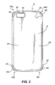
FIG. 2 illustrates a rear view of a case for a mobile device, according to an embodiment of the present disclosure.
FIG. 3 illustrates a side view of a case for a mobile device, according to an embodiment of the present disclosure.
FIG. 4 illustrates a side view of a case for a mobile device, according to an embodiment of the present disclosure.
FIG. 5 illustrates a top view of a case for a mobile device, according to an embodiment of the present disclosure.
FIG. 6 illustrates a bottom view of a case for a mobile device, according to an embodiment of the present disclosure.
FIG. 7 illustrates a front side perspective view of a case for a mobile device, according to an embodiment of the present disclosure.
FIG. 8 illustrates a front side perspective view of a case for a mobile device, according to an embodiment of the present disclosure.
FIG. 9 illustrates a front side perspective view of a case for a mobile device, according to an embodiment of the present disclosure.
FIG. 10 illustrates a front side perspective view of a case for a mobile device, according to an embodiment of the present disclosure.
FIG. 11 illustrates a rear side perspective view of a case for a mobile device, according to an embodiment of the present disclosure.
FIG. 12 illustrates a front side perspective view of a case for a mobile device showing side wall cushion devices separated from side walls and a base wall of the case, according to an embodiment of the present disclosure.
FIG. 13 illustrates a front perspective view of a side wall cushion device, according to an embodiment of the present disclosure.
FIG. 14 illustrates a rear perspective view of a side wall cushion device, according to an embodiment of the present disclosure.
FIG. 15 illustrates a perspective view of a corner of a case, according to an embodiment of the present disclosure.
FIG. 16 illustrates a cross sectional view of a corner of a case, according to an embodiment of the present disclosure.
FIG. 17 illustrates a cross sectional view taken along a width of a case, according to an embodiment of the present disclosure.
FIG. 18 illustrates a cross sectional view taken along a length of a case, according to an embodiment of the present disclosure.
FIG. 19 illustrates a front perspective view of a case with a mobile device received by a recess of the case, according to an embodiment of the present disclosure.
DETAILED DESCRIPTION OF THE PREFERRED EMBODIMENTS
FIG. 1 illustrates a front view of a case 10 for a mobile device. The case 10 includes a base wall 12 and a plurality of side walls 14 a-d (referred to collectively as 14). The side walls 14 extend away from the base wall 12 to form a recess 16 configured to receive the mobile device. A plurality of cushion devices 18 a-d (referred to collectively as 18) extend through the side walls 14. A cushion device 20 is positioned upon the base wall 12. An aperture 22 is positioned on the base wall 12.
The base wall 12 is a covering that covers a surface of the mobile device that is received by the recess 16. The base wall 12 extends out from a central portion 24 of the case 10 to outer portions 26 of the case 10 to form the covering.
The base wall 12 includes an inner surface 28 and an outer surface 30 (shown in FIG. 2). The inner surface 28 faces towards the mobile device when the mobile device is received in the recess 16. The outer surface 30 faces away from the mobile device when the mobile device is received in the recess 16.
The base wall 12 may have a substantially flat shape and extend in a single plane. The flat shape of the base wall 12 may match a shape of a portion of the mobile device to be retained by the case 10. For example, a back portion of the mobile device may have a substantially flat shape, and the base wall 12 similarly includes the flat shape to contour to the back portion of the mobile device. The contour of the base wall 12 forms a form-fit of the mobile device, to allow the case 10 to not be overly bulky when covering the mobile device.
The base wall 12 may extend outward from the central portion 24 of the case 10 to form a substantially rectangular shape. The rectangular shape may be formed to match the shape of a rectangular mobile device that is contained within the case 10. The outer portions 26 of the case 10 terminate at the outer portions of the mobile device that is contained therein.
The shape of the base wall 12 may be configured in any shape as desired based on the shape of the mobile device to be retained. For example, in one embodiment, the base wall 12 may have a curved shape. The curvature of the base wall 12 may match a shape of the portion of the mobile device to be retained. The base wall 12 may be dimensioned to match dimensions of the mobile device as desired, for example, the base wall 12 may be dimensioned to have a square, or oblong shape to match the dimensions of a mobile device as desired. In one embodiment, the base wall 12 may not match the shape of the mobile device, but may have any shape that still allows the base wall 12 to cover a surface of the mobile device.
The base wall 12 may include a single layer or multi-layer construction. In the embodiment shown in FIG. 1, the base wall 12 has a multi-layer construction, including an interior layer 32 and an exterior layer 34 (shown in FIG. 2). The interior layer 32 forms a portion of the inner surface 28 of the base wall 12. The exterior layer 34 forms a portion of the exterior surface 30 of the base wall 12. The interior layer 32 and exterior layer 34 may be bonded or joined together in a manner that the layers 32, 34 are permanently combined together. In one embodiment, the layers 32, 34 may be molded together. In one embodiment, the interior layer 32 may be overmolded upon the exterior layer 34.
The interior layer 32 may be made of a pliable material that is sufficiently rigid to form a portion of the case 10, yet offers an amount of shock resistance for the mobile device contained therein. The interior layer 32 may comprise an elastomeric material, for example an elastomeric polymer or the like configured to provide shock resistance for the mobile device. In one embodiment, the interior layer 32 may be made from an elastomeric thermoplastic polyurethane. The exterior layer 34 (shown in FIG. 2) may be made of a material that is less pliable than the material of the interior layer 32, and may have a greater hardness than the material of the interior layer 32. The material of the exterior layer 34 may offer greater penetration resistance for the case 10 than the material forming the interior layer 32. The exterior layer 34 may comprise a hard plastic, for example, polycarbonate or the like. In other embodiments, the interior layer 32 and exterior layer 34 may be made of identical materials, or materials having similar properties, or may be made of any combination of materials as desired.
The side walls 14 extend from the base wall 12 to cover a side surface of the mobile device that is received in the recess 16. The combination of the side walls 14 and the base wall 12 forms a housing, or shell, of the case 10 for receiving the mobile device. The side walls 14 may extend from the outer edges of the base wall 12 to form the outer portions 26 of the case 10. The side walls 14 may be shaped to contour to the sides of the mobile device, to form a form-fit with the sides of the mobile device, such that the case 10 is not bulky upon the sides of the mobile device. In other embodiments, the side walls 14 may have any shape relative to the mobile device as desired to cover the sides of the mobile device.
Each of the side walls 14 includes a respective inner surface 36 a, 36 b, 36 c, 36 d (referred to collectively as 36) and an outer surface 38 a, 38 b, 38 c, 38 d (referred to collectively as 38). Each of the inner surfaces 36 face towards the mobile device when it is received in the recess 16. Each of the outer surfaces 38 face away from the mobile device when it is received in the recess 16.
The side walls 14 may extend upward from the base wall 12 to a distance that that extends over the side of the mobile device or matches the height of the side of the mobile device. In one embodiment, any of the side walls 14 may extend upward from the base wall 12 such that only a part of the side of the mobile device is covered.
Each of the side walls 14 may be formed of a continuous piece of material or may be formed of a material that includes apertures or cut-outs through any of the respective side walls 14. A portion of the interior layer 32 may extend from the base wall 12 to form a portion of any of the side walls 14 as desired. The portion of the interior layer 32 forming a part of the side walls 14 may be integral with the interior layer 32 of the base wall 12. In an embodiment in which the interior layer 32 is a pliable material, the pliability of the interior layer 32 as utilized by the side walls 14 may allow the side walls 14 to more easily bend to allow the mobile device to be more easily inserted into the recess 16.
A portion of the exterior layer 34 (shown in FIG. 2) may extend from the base wall 12 to form a portion of any of the side walls 14 as desired. The portion of the exterior layer 34 forming a part of the side walls 14 may be integral with the exterior layer 34 of the base wall 12. In an embodiment in which the exterior layer 34 is a rigid material, the rigidity of the exterior layer 34 as utilized by the side walls 14 may provide greater support for the side walls 14 to maintain their shape when the mobile device is received by the recess 16. In one embodiment, any of the side walls 14 may be formed from a single piece of material. In one embodiment, any of the side walls 14 may be formed from multiple pieces of material. In one embodiment, any of the side walls 14 may be formed from material that is not integral with a portion of the base wall 12.
The side walls 14 may extend from the base wall 12 in a direction that is substantially perpendicular, or ninety degrees from a direction the base wall 12 extends in. In the embodiment shown in FIG. 1, the base wall 12 has a substantially flat shape, with each of the side walls 14 similarly having a flat shape that extends in a direction substantially perpendicular to the plane of the base wall 12. In one embodiment, any of the side walls 14 may have a curved shape, yet may have a portion that extends in a direction substantially perpendicular to a direction that a portion of the base wall 12 extends in. In one embodiment, any of the side walls 14 may have any shape as desired relative to the base wall 12 such that a side surface of the mobile device is covered. The side walls 14 in combination may form a rim around the base wall 12 that allow side surfaces of the mobile device to be covered. The rim may extend around the sides surfaces of the mobile device to form corners that match the position of corners of the mobile device.
The side walls 14 may extend relative to each other in a direction that is substantially perpendicular or ninety (90) degrees from a direction that an adjacent one of the side walls 14 extends in. The side walls 14 may form a substantially rectangular, or box-like, shape that covers side surfaces of the mobile device. In one embodiment, any of the side walls 14 may have a curved shape, yet may have a portion that extends in a direction substantially perpendicular to a direction that an adjacent one of the side walls 14 extends in.
The combination of the inner surface 28 of the base wall 12 and the inner surfaces 36 of the side walls 14 form the recess 16 for receiving the mobile device. The recess 16 is bounded on its sides by the side walls 14. The recess 16 is bounded at its bottom by the base wall 12. The top of the recess opens into an aperture 40 that the mobile device passes through to be received by the recess 16. In the embodiment shown in FIG. 1, four side walls 14 bound the four sides of the recess 16. In one embodiment, any number of side walls 14 may be utilized to bound the recess 16 as desired. A recess 16 may be formed through use of two side walls extending at a distance from the base wall 12, with the distance defining the indentation or cavity that the mobile device is received in.
The cushion devices 18 extend through respective apertures 58 a, 58 b, 58 c, 58 d (referred to collectively as 58) (identified in FIG. 12) positioned in the side walls 14 that extend from the inner surfaces 36 of the side walls 14 to the outer surfaces 38 of the side walls 14. The apertures may be positioned at corners 42 a, 42 b, 42 c, 42 d (referred to collectively as 42) of the case 10. Side walls 14 adjacent to one another join at the respective corners 42, and form an angle relative to each other.
The cushion devices 18 are configured to cushion the mobile device from a force exerted upon the case 10. The cushion devices 18 may be formed from shock absorbing material, which may be elastic. Such materials may include an elastomeric material such as rubber, or the like. In one embodiment, the cushion devices 18 may be formed of material having a durometer between approximately 30-60. The cushion devices 18 may be made of a material that has greater resistance to shock than the materials forming the base wall 12 and the side walls 14. The cushion devices 18 may be structured to substantially absorb a force, or part of a force, applied to the case 10 such that the entirety of the force is not transmitted directly to the mobile device. The cushion devices 18 may deform upon the force being applied, to absorb energy of the force. The cushion devices 18 may serve to reduce the possibility of damage to the mobile device if the case 10 is dropped or hit by an object.
The cushion devices 18 may additionally serve to reduce force that is transmitted to the remainder of the case 10. For example, the cushion devices 18 may reduce force applied to the base layer 12 or side walls 14 forming the housing or shell of the case 10. The cushion devices 18 may be removable from the apertures such that the cushion devices 18 are not permanently joined to the remainder of the case 10. The removable feature of the cushion devices 18 may serve to reduce the force that is transmitted to the remainder of the case 10. The cushion devices 18 may lack a chemical or electrical bond to the remainder of the case 10 that reduces the strength of the force transmitted thereto. In addition, the cushion devices 18 may be removable to allow different cushion devices 18, having different properties (e.g., hardness, durability, elasticity, and the like) to be inserted and placed in the apertures. The removable feature additionally may allow the cushion devices 18 to be more easily made of a different material than the base wall 12 or the side wall 14 of the case 10. The cushion devices 18 may be formed separate from the base wall 12 and side wall and then inserted manually into the apertures. The manual insertion process may reduce manufacturing expense, by reducing the need for a separate molding step to form the cushion devices 20 in place. In addition, the manual insertion process may allow a distributor to more easily select different cushion devices with different properties (e.g., hardness, durability, elasticity, and the like) to be inserted and placed in the apertures based on a particular shape or style of a desired mobile device. The case 10 may be fitted for a particular shape or style of mobile device after the factory manufacturing process takes place, for example, a salesperson may fit the case 10 in-store, or at the point of sale, for a particular mobile device. Although the cushion devices may be removable, in one embodiment, they may not be intended for the end-consumer to remove the cushion device, because the mobile device will not properly fit in the case 10 with the cushion devices removed. In addition, an end-consumer may damage a cushion device if they attempt to remove the cushion device from the case 10. In one embodiment, the cushion devices 18 may be permanently fixed to the side walls 14 of the case.
The cushion devices 18 may be positioned at any location desired along the side walls 14 to reduce a force from being transmitted to the mobile device. Preferably, the cushion devices 18 are positioned at the corners 42 of the case 10 to stabilize the mobile device at its vertices. In addition, a force applied directly to the case corners 42 will likely be more focused because it is not distributed along a long surface of the case 10, such as along a length of one of the side walls 14 or the length of the outer surface 30 of the base wall 12 (shown in FIG. 2). The cushion devices 18 at the corners may dissipate this focused force and reduce its transmission to the mobile device.
The number of cushion devices 18 utilized may also be varied. Preferably, in an embodiment in which the cushion devices 18 are positioned at the corners 42 of the case, a cushion device 18 will be positioned at each corner. For an embodiment in which the mobile device has four corners, then four cushion devices 18 may be utilized. However, shock absorption may still be provided if a cushion device 18 is not positioned at each corner. In one embodiment, only one cushion device 18 may be utilized at one corner, to provide some shock absorption for the mobile device. In an embodiment in which cushion devices 18 are positioned at multiple locations along the side walls 14, any number of cushion devices 18 may be utilized as desired to provide shock absorption. Cushion devices 18 may extend through apertures positioned in the middle of each of the side walls 14, for example.
The cushion device 20 positioned upon the base wall 12 may be configured to cushion the mobile device from a force exerted upon the case 10, similar to the cushion devices 18 extending through the side walls 14. The cushion device 20 positioned upon the base wall 12 may be referred to as a base wall cushion device 20 and the cushion devices 18 extending through the side walls 14 may be referred to as side wall cushion devices 18. The base wall cushion device 20 may be formed from shock absorbing material, which may be elastic. Such materials may include an elastomeric material such as rubber, or the like. In one embodiment, the cushion devices 18 may be formed of material having a durometer between approximately 30-60. The base wall cushion device 20 may be made of a material that has greater resistance to shock than the materials forming the base wall 12 and the side walls 14. The base wall cushion device 20 may be structured to substantially absorb a force, or part of a force, applied to the case 10 such that the entirety of the force is not transmitted directly to the mobile device. The base wall cushion device 20 may deform upon the force being applied, to absorb energy provided by the force. The base wall cushion device 20 may serve to reduce the possibility of damage to the mobile device if the case 10 is dropped or hit by an object.
The base wall cushion device 20 may not be formed integrally with the base wall 12. The base wall cushion device 20 may be formed separate from the base wall 12 to allow the cushion device 20 to be made of a different material than the base wall 12. The base wall cushion device 20 may be formed separate and fixed to the base wall 12 through an adhesive, or may be mechanically joined to the base wall 12. In one embodiment, the base wall cushion device 20 may be formed integral with the base wall 12 through a molding process.
The base wall cushion device 20 is preferably positioned at a central location along the base wall 12, as shown in FIG. 1. However, the base wall cushion device 20 may be positioned at variable locations as desired. Any number of additional base wall cushion devices 20 may be utilized, for example, sufficient numbers of cushion devices 20 may be utilized to substantially entirely cover the base wall 12.
The base wall cushion device 20 is preferably shaped to have a surface area that contacts a surface of the mobile device at multiple locations. Contact at multiple locations allows any force transmitted through the cushion device 20 to be distributed to the multiple locations on the surface of the mobile device. The base wall cushion device 20 preferably has a substantially flattened or planar contact surface that contacts the surface of the mobile device and distributes the reduced force substantially evenly along the contact surface. The base wall cushion device 20 may have any outline or dimensional shape, as desired, including a rectangular shape as shown in FIG. 1, or a diamond, or circular shape, as desired.
The aperture 22 is positioned on the base wall 12 and extends from the inner surface 28 to the outer surface 30 of the base wall 12. The aperture 22 is configured to allow an element of the mobile device to be utilized through the case 10. The aperture 22 shown in FIG. 1, for example, corresponds to a camera used by the mobile device. The base wall 12 and side walls 14 may include any number of apertures or cut outs as desired, to correspond to an element of the mobile device or to otherwise allow access to the mobile device through the case 10. Apertures or cut outs may be positioned in the base wall 12 and any of the side walls 14 to reduce the weight of the case 10, for example.
FIG. 2 illustrates a rear view of the case 10 showing the outer surface 30 of the base wall 12. The exterior layer 34 of the base wall 12 forms a portion of the outer surface 30 of the base wall 12. The interior layer 32 of the base wall 12 may pass through a portion of the exterior layer 34 to form a portion of the outer surface 30 of the base wall 12. In the embodiment shown in FIG. 2, the interior layer 32 extends through the exterior layer 34 at the corners 42 of the case 10. In one embodiment, the interior layer 32 may not extend through the exterior layer 34. In one embodiment, the interior layer 32 may pass through any portion of the exterior layer 34 as desired. In an embodiment in which the interior layer 32 is a pliable material, and the exterior layer 34 is a rigid material, the proportionate amount of interior layer 32 that extends through the exterior layer 34 may be determined based on the total amount of pliability or rigidity desired for the case 10.
FIG. 3 illustrates a side view of the case 10 showing the outer surface 38 d of one of the side walls 14. The exterior layer 34 extends upward from the base wall 12 (shown in FIG. 2) to form a portion of the outer surface 38 d of the side wall 14 d. The interior layer 32 of the base wall 12 extends upward from the base wall 12 to form a portion of the outer surface 38 d of the side wall 14 d. The interior layer 32 may pass through a portion of the exterior layer 34.
The interior layer 32 may form grips 44 on the outer surface 38 d of the side wall 14 d. The grips 44 are configured to reduce the possibility that the case 10 slips from a user's hand while the case 10 is being gripped. The interior layer 32 may also form depressible portions 46 on the outer surface 38 d of the side wall 14 d. The depressible portions 46 may be used to transmit a force to elements on the mobile device, including buttons, for example. An aperture 48 may be positioned on the side wall 14 d to allow access to the mobile device through the case 10. The aperture 48 shown in FIG. 3 allows access to a switch on the mobile device.
FIG. 4 illustrates a side view of the case 10 showing the outer surface 38 b of one of the side walls 14. The exterior layer 34 extends upward from the base wall 12 (shown in FIG. 2) to form a portion of the outer surface 38 b of the side wall 14 b. The interior layer 32 of the base wall 12 extends upward from the base wall 12 to form a portion of the outer surface 38 b of the side wall 14 b. The interior layer 32 may pass through a portion of the exterior layer 34. The interior layer 32 may form grips 50 on the outer surface 38 b of the side wall 14 b, serving a similar function as the grips 44 shown in FIG. 3.
FIG. 5 illustrates a top view of the case 10 showing the outer surface 38 a of one of the side walls 14. The exterior layer 34 extends upward from the base wall 12 (shown in FIG. 2) to form a portion of the outer surface 38 a of the side wall 14 a. The interior layer 32 of the base wall 12 extends upward from the base wall 12 to form a portion of the outer surface 38 a of the side wall 14 a. The interior layer 32 may pass through a portion of the exterior layer 34. The interior layer 32 may form a depressible portion 52 on the outer surface 38 a of the side wall 14 a, that serves a similar function as the depressible portion 46 shown in FIG. 3.
FIG. 6 illustrates a bottom view of the case 10 showing the outer surface 38 c of one of the side walls 14. The exterior layer 34 extends upward from the base wall 12 (shown in FIG. 2) to form a portion of the outer surface 38 c of the side wall 14 c. The interior layer 32 of the base wall 12 extends upward from the base wall 12 to form a portion of the outer surface 38 o of the side wall 14 c. The interior layer 32 may pass through a portion of the exterior layer 34. An aperture 54 may be positioned on the side wall 14 c to allow access to the mobile device through the case 10. The aperture 54 shown in FIG. 6 allows access to electrical connectors on the mobile device.
In one embodiment, the interior layer 32 may not extend through the exterior layer 34 of the side walls 14 shown in FIGS. 3-6. In one embodiment, the interior layer 32 may pass through any portion of the exterior layer 34 of the side walls 14 as desired. In an embodiment in which the interior layer 32 is a pliable material, and the exterior layer 34 is a rigid material, the proportionate amount of interior layer 32 that extends through the exterior layer 34 may be determined based on the total amount of pliability or rigidity desired for the side walls 14 of the case 10. A rigid exterior layer 34 extending over the side walls 14 may form a rigid shell around the interior layer 32.
FIG. 7 illustrates a front side perspective view of the case 10. The interior surfaces 36 b, 36 c of two of the side walls 14 are shown. The interior layer 32 of the base wall 12 extends upward from the base wall 12 to form a portion of the interior surfaces 36 b, 36 c of the side walls 14 b, 14 c.
A lip 56 extends from the side walls 14 towards the interior of the case 10. The lip 56 is positioned at an end of the side walls 14 that is opposite an end of each of the side walls 14 fixed to the base wall 12. The lip 56 is configured to retain the mobile device within the recess 16 upon the mobile device being inserted into the recess 16. The lip 56 may extend continuously around the side walls 14 of the case 10 or may extend over only a portion of at least one of the side walls 14. The lip 56 may be formed from the material forming the interior layer 32 of the base wall 12. The lip 56 may define the bounds of the aperture 40 that the mobile device passes through to be received by the recess 16.
A portion of each of the side wall cushion devices 18 extends into the interior of the case 10. The portion of the side wall cushion devices 18 that extends into the interior of the case 10 is configured to contact the mobile device to cushion the mobile device from a force.
FIG. 8 illustrates a front side perspective view of the case 10. The interior surfaces 36 c, 36 d of two of the side walls 14 are shown. The interior layer 32 of the base wall 12 extends upward from the base wall 12 to form a portion of the interior surfaces 36 c, 36 d of the side walls 14 c, 14 d.
FIG. 9 illustrates a front side perspective view of the case 10. The interior surfaces 36 a, 36 b of two of the side walls 14 are shown. The interior layer 32 of the base wall 12 extends upward from the base wall 12 to form a portion of the interior surfaces 36 a, 36 b of the side walls 14 a, 14 b.
FIG. 10 illustrates a front side perspective view of the case 10. The interior surfaces 36 a, 36 d of two of the side walls 14 are shown. The interior layer 32 of the base wall 12 extends upward from the base wall 12 to form a portion of the interior surfaces 36 a, 36 d of the side walls 14 a, 14 d.
FIG. 11 illustrates a rear side perspective view of the case 10.
FIG. 12 illustrates an embodiment of the case 10 in which the side wall cushion devices 18 are removable from the side walls 14 and the base wall 12 of the case 10. The side wall cushion devices 18 are shown separated from the side walls 14 and the base wall 12 of the case 10. The case 10 is not intended to be in an operable mode when the side wall cushion devices 18 are removed, because the mobile device may not properly fit within the case 10 without the cushion devices 18 in place. The apertures 58 b and 58 d are configured similarly as the apertures 58 a and 58 c.
FIG. 13 illustrates a front perspective view of one of the side wall cushion devices 18. Each of the side wall cushion devices 18 shown in FIG. 12 may be configured similarly as the cushion device 18 a shown in FIG. 13. In one embodiment, any or all of the cushion devices 18 may be configured differently, as desired.
The side wall cushion device 18 a includes an inner flange 60 and an outer flange 62 connected by a neck 64. The inner flange 60 is a portion of the cushion device 18 a positioned interior of the side walls 14 when the cushion device 18 a is inserted through a respective aperture 58 a (shown in FIG. 12). The outer flange 62 is a portion of the cushion device 18 a positioned exterior of the side walls 14 when the cushion device 18 a is inserted through a respective aperture 58 a. The outer flange 62 and inner flange 60 may secure the cushion device 18 a within the aperture 58 a. The neck 64 is positioned within the respective aperture 58 a when the cushion device 18 a extends through the aperture 58 a.
The outer flange 62 is preferably sized larger than the size of the respective aperture 58 a (shown in FIG. 12) to prevent the cushion device 18 a from becoming dislodged from the aperture 58 a. The outer flange 62 is preferably sized to have an outer surface area that is large, and larger than the area of the aperture 58 a, to provide material that receives and absorbs force applied to the outer flange 62.
The outer flange 62 may have a shape that contours to the shape of the respective outer surfaces 38 a, 38 b of the side walls 14 a, 14 b (shown in FIGS. 4 and 5). The outer flange 62 may have a curved or angled shape when the cushion device 18 a is positioned at the corner of the case 10. The outer flange 62 may have sufficient length to cover the respective outer surfaces 38 a, 38 b of side walls 14 a, 14 b at the corner of the case 10, to absorb force applied to the corner of the case 10. In the embodiment shown in FIG. 13, the outer flange 62 has an oblong or oval shape. In other embodiments, the outer flange 62 may have any shape that retains the cushion device 18 a within the respective aperture 58 a as desired.
The inner flange 60 is preferably sized larger than the size of the respective aperture 58 a (shown in FIG. 12) to prevent the cushion device 18 a from becoming dislodged from the aperture 58 a. The inner flange 60 is preferably sized to have an interior surface area that is large, and larger than the area of the aperture 58 a, to provide material that absorbs force applied to the outer flange 62 and preferably does not deliver the entirety of the force to the mobile device.
The inner flange 60 may include a horizontal support 66, a stabilizer 68, and a vertical support 70. The vertical support 70 may be contoured to form a corner recess 72.
The horizontal support 66 may comprise a flattened protrusion extending outward from the inner flange 60. When the cushion device 18 a is inserted into the respective aperture 58 a (shown in FIG. 12), the horizontal support 66 may extend such that a portion of the mobile device may rest upon the horizontal support 66. The horizontal support 66 may have a thickness, or distance, from the base wall 12 (shown in FIG. 1) such that the mobile device does not contact the base wall 12 when resting upon the horizontal support 66. The horizontal support 66 may reduce the possibility that force is directly transmitted from the base wall 12 to the mobile device through contact therebetween.
The stabilizer 68 may comprise a ridge that extends from the inner flange 60 and contacts a portion of the base wall 12 (shown in FIG. 1). The stabilizer 68 may contact the base wall 12 to align the inner flange 60 in position when it is inserted through the respective aperture 58 a (shown in FIG. 12).
The vertical support 70 may comprise a flattened wall that fits against and covers the respective interior surfaces 36 a, 36 b of the side walls 14 a, 14 b (shown in FIG. 9). When the cushion device 18 a is inserted into the respective aperture 58 a (shown in FIG. 12), the vertical support 70 may extend such that a portion of the mobile device may press against the vertical support 70. The vertical support 70 may have a thickness, or distance, from the respective side walls 14 a, 14 b (shown in FIG. 9) such that the mobile device does not contact the respective side walls 14 a, 14 b when pressing against the vertical support 70. The vertical support 70 may reduce the possibility that force is directly transmitted from one of the side walls 14 to the mobile device through contact therebetween. The vertical support 70 may have a height, or distance, such that an entire height of the respective inner surfaces 36 a, 36 b of the side walls 14 a, 14 b below the lip 56 are filled with the vertical support 70.
The corner recess 72 is shaped to receive a corner of the mobile device. The vertical support 70 may be curved to extend around the corner of the mobile device to provide cushioning support for the corner in directions towards both of the adjacent side walls 14 a, 14 b (shown in FIG. 9).
In other embodiments, the inner flange 60 may have any shape as desired to provide cushioning for the mobile device when retained by the case. For example, in an embodiment in which the cushion support 18 a is not utilized in the corner of the case, but is rather utilized along a midpoint of one of the side walls, then the vertical support 70 may not be contoured to include a corner recess 72.
FIG. 14 illustrates a rear perspective view of the side wall cushion device 18 a showing the outer flange 62. In one embodiment, the outer flange 62 and/or inner flange 60 may be configured such that the outer flange 62 and/or inner flange 60 must deform to allow the cushion device 18 to pass through the respective aperture 58 a, to allow the cushion device 18 a to be retained within the aperture 58 a, or removed from the aperture 58 a.
FIG. 15 illustrates a detail view of one of the corners 42 of the case 10, with the respective side wall cushion device 18 a removed. Each of the corners 42 shown in FIGS. 7-10 may be configured similarly as the corner 42 a shown in FIG. 15. In one embodiment, any or all of the corners 42 may be configured differently, as desired.
Two of the side walls 14 a, 14 b join at the corner 42 a, and the aperture 58 a extends through a portion of each of the side walls 14 a, 14 b. Each of the side walls 14 a, 14 b join with each other at approximately a midpoint of the aperture 58 a. The side walls 14 a, 14 b may be mechanically joined at the aperture 58 a or may be integrally formed such that they are joined with one another at the aperture 58 a. The ends of the side walls 14 a, 14 b entirely encircle the cushion device 18 a when it is inserted through the aperture 58 a. In one embodiment, the aperture 58 a may be positioned at the corner 42 a, but may be offset from the position shown in FIG. 15, such that the aperture 58 a only extends through one of the two side walls 14 a, 14 b.
A side wall recess 74 is cut into the side walls 14 a, 14 b at the corner 42 a. The side wall recess 74 is preferably shaped to securely receive and retain the side wall cushion device 18 a when it is passed through the aperture 58 a.
FIG. 16 illustrates a cross sectional view of one of the corners 42 a of the case 10, with the respective side wall cushion device 18 a extending through the aperture 58 a. Each of the corners 42 shown in FIGS. 7-10 may be configured similarly as the corner 42 a shown in FIG. 16. In one embodiment, any or all of the corners 42 may be configured differently, as desired.
The cushion device 18 a fills the side wall recess 74 shown in FIG. 15. The outer flange 62 is positioned exterior to the respective side walls 14 a, 14 b (shown in FIG. 15). The inner flange 60 is positioned interior to the respective side walls 14 a, 14 b. The stabilizer 68 abuts the interior layer 32 and the exterior layer 34 to align the inner flange 60 in position when it is inserted through the aperture 58 a. The horizontal support 66 abuts the interior layer 32 and extends at a distance 76 from the interior surface 28 of the base wall 12. The distance 76 allows a gap to form between the mobile device and the inner surface 28 of the base wall 12 when the mobile device is received by the recess 16. The vertical support 70 abuts the inner surfaces 36 a, 36 b (shown in FIG. 15) and extends at a distance from the inner surfaces, as more clearly shown in FIG. 17.
FIG. 17 illustrates a cross sectional view taken along a width of the case 10. An exemplary mobile device 78 is shown in outline that has been received by the recess 16 of the case 10. Like components of the side wall cushion devices 18 a, 18 d have been marked with lettering for identification purposes ( vertical support 70 a, 70 d, horizontal support 66 a, 66 d), such components having similar properties as discussed regarding the vertical support 70 and the horizontal support 66.
The vertical supports 70 a, 70 d extend at respective distances 80, 82 from respective inner surfaces 36 b, 36 d of the side walls 14 b, 14 d. The distances 80, 82 allow gaps to form between the mobile device and the respective inner surfaces 36 b, 36 d of the side walls 14 b, 14 d when the mobile device 78 is received by the recess 16. The distance 76 of the respective horizontal supports 66 a, 66 d from the inner surface 28 of the base wall 12 is shown, with a gap shown between the inner surface 28 of the base wall 12 and the mobile device 78.
The distance 76 of the respective horizontal supports 66 a, 66 d from the inner surface 28 may match a distance that the base wall cushion device 20 has from the inner surface 28 of the base wall 12. The base wall cushion device 20 extends from the base wall 12 to a distance 76 such that the mobile device 78 contacts the base wall cushion device 20 and a gap exists between the mobile device 78 and the inner surface 28 of the base wall 12 when the mobile device 78 is received in the recess 16. The combination of the distances 76 of the cushion devices 18, 20 from the base wall 12 may collectively elevate the mobile device 78 above the inner surface 28 of the base wall 12. The lip 56 forms the upper restraint on the mobile device 78. The cushion devices 18, 20 may be configured to press the mobile device 78 against the lip 56 to secure the mobile device 78 within the recess 16. In one embodiment, the distance of the base wall cushion device 20 from the inner surface 28 of the base wall 12 may differ from the corresponding distances of the cushion devices. In an embodiment in which side wall cushion devices 18 are not utilized, the base wall cushion device 20 may solely form the gap between the mobile device 78 and the base wall 12. In an embodiment in which a base wall cushion device is not utilized, the side wall cushion devices 18 may solely form the gap between the mobile device 78 and the base wall 12.
FIG. 18 illustrates a cross sectional view taken along a length of the case 10. Like components of the side wall cushion devices 18 a, 18 b have been marked with lettering for identification purposes ( vertical support 70 a, 70 b, horizontal support 66 a, 66 b), such components having similar properties as discussed regarding the vertical support 70 and the horizontal support 66.
The vertical supports 70 a, 70 b extend at respective distances 84, 86 from respective inner surfaces 36 a, 36 c of the side wails 14 a, 14 c. The distances 84, 86 serve similar functions as the distances 80, 82 discussed in regard to FIG. 17, namely, the distances 84, 86 allow gaps to form between the mobile device and the respective inner surfaces 36 a, 36 c of the side walls 14 a, 14 c when the mobile device 78 is retained by the case 10.
FIG. 19 illustrates a front perspective view of the case 10 with the mobile device 78 received by the recess 16 (shown in FIG. 7). The lip 56 overlaps a front surface of the mobile device 78 to secure the device 78 within the recess 16. The aperture 40 allows a user to access front portions of the mobile device 78.
The case 10 may be configured as a form-fit case, as illustrated in FIG. 19, or may be configured as a bulky shell that does not tightly fit the contours of the mobile device. A form-fit case has a base wall and side walls that are positioned substantially at the outer surfaces of the mobile device. The case 10 may be shaped to fit a particular intended model of mobile device, or may be shaped to fit multiple different models of mobile devices. The case 10 may be sized as desired, to fit a corresponding mobile device. The case 10 may be formed as a single piece case, in which the side wall cushion devices 18 are permanently joined to the side walls 14, and the entire case forms a single piece. The case 10 may be formed as a multi-piece case, as shown in FIG. 12, for example, in which side wall cushion devices 18 are removable from the side walls 14, or any other number of pieces are utilized to cover the mobile device. For example, in one embodiment, a cover may be fit over the side of the case 10 opposite the base wall 12, to form a case 10 covering the mobile device on six sides.
The case 10 may be configured to cover a back surface of the mobile device, or a front surface of the mobile device, or both, if desired.
The mobile device is preferably a personal electronic device such as a phone, a computer, a digital assistant, hand held device, or the like. The phone may comprise a cellular, or mobile phone, and may include a touch screen. The case 10 may be configured to cover the side of the phone opposite the touch screen, to protect the back of the phone from impact and/or scratches. The case 10 may also be configured to cover portions of the touch screen, with cut outs or apertures in place to allow access to the desired elements of the touch screen. The computer may comprise a tablet computer or the like, which may similarly include a touch screen accessible with the case 10 in place. The hand held device may comprise a personal digital assistant or the like, which may similarly include a touch screen accessible with the case 10 in place.
The case 10 beneficially covers and protects the desired mobile device while offering shock protection for the mobile device. Impact dampening material is strategically placed to absorb shock in a drop event. Such protection may extend the life of the mobile device by reducing the possibility of damage to electronic components within the mobile device. The cushion devices disclosed herein may absorb a force applied to the case by deforming to absorb the force or by providing shock resistance in any other manner desired. The cushion devices may additionally separate the mobile device away from the surfaces of the base wall and the side walls to reduce the force transmitted from these surfaces to the mobile device. The mobile device may float, or be suspended upon the cushion devices to reduce shock to the mobile device. In an embodiment in which a base wall cushion device 20 and side wall cushion devices 18 are used, the mobile device may be suspended at five points by the impact protection material of the cushion devices.
In closing, it is to be understood that although aspects of the present specification are highlighted by referring to specific embodiments, one skilled in the art will readily appreciate that these disclosed embodiments are only illustrative of the principles of the subject matter disclosed herein. Therefore, it should be understood that the disclosed subject matter is in no way limited to a particular methodology, protocol, and/or reagent, etc., described herein. As such, various modifications or changes to or alternative configurations of the disclosed subject matter can be made in accordance with the teachings herein without departing from the spirit of the present specification. Lastly, the terminology used herein is for the purpose of describing particular embodiments only, and is not intended to limit the scope of the present invention, which is defined solely by the claims. Accordingly, the present invention is not limited to that precisely as shown and described.
Certain embodiments of the present invention are described herein, including the best mode known to the inventors for carrying out the invention. Of course, variations on these described embodiments will become apparent to those of ordinary skill in the art upon reading the foregoing description. The inventor expects skilled artisans to employ such variations as appropriate, and the inventors intend for the present invention to be practiced otherwise than specifically described herein. Accordingly, this invention includes all modifications and equivalents of the subject matter recited in the claims appended hereto as permitted by applicable law. Moreover, any combination of the above-described embodiments in all possible variations thereof is encompassed by the invention unless otherwise indicated herein or otherwise clearly contradicted by context.
Groupings of alternative embodiments, elements, or steps of the present invention are not to be construed as limitations. Each group member may be referred to and claimed individually or in any combination with other group members disclosed herein. It is anticipated that one or more members of a group may be included in, or deleted from, a group for reasons of convenience and/or patentability. When any such inclusion or deletion occurs, the specification is deemed to contain the group as modified thus fulfilling the written description of all Markush groups used in the appended claims.
Unless otherwise indicated, all numbers expressing a characteristic, item, quantity, parameter, property, term, and so forth used in the present specification and claims are to be understood as being modified in all instances by the term “about.” As used herein, the term “about” means that the characteristic, item, quantity, parameter, property, or term so qualified encompasses a range of plus or minus ten percent above and below the value of the stated characteristic, item, quantity, parameter, property, or term. Accordingly, unless indicated to the contrary, the numerical parameters set forth in the specification and attached claims are approximations that may vary. At the very least, and not as an attempt to limit the application of the doctrine of equivalents to the scope of the claims, each numerical indication should at least be construed in light of the number of reported significant digits and by applying ordinary rounding techniques. Notwithstanding that the numerical ranges and values setting forth the broad scope of the invention are approximations, the numerical ranges and values set forth in the specific examples are reported as precisely as possible. Any numerical range or value, however, inherently contains certain errors necessarily resulting from the standard deviation found in their respective testing measurements. Recitation of numerical ranges of values herein is merely intended to serve as a shorthand method of referring individually to each separate numerical value falling within the range. Unless otherwise indicated herein, each individual value of a numerical range is incorporated into the present specification as if it were individually recited herein.
The terms “a,” “an,” “the” and similar referents used in the context of describing the present invention (especially in the context of the following claims) are to be construed to cover both the singular and the plural, unless otherwise indicated herein or clearly contradicted by context. All methods described herein can be performed in any suitable order unless otherwise indicated herein or otherwise clearly contradicted by context. The use of any and all examples, or exemplary language (e.g., “such as”) provided herein is intended merely to better illuminate the present invention and does not pose a limitation on the scope of the invention otherwise claimed. No language in the present specification should be construed as indicating any non-claimed element essential to the practice of the invention.
Specific embodiments disclosed herein may be further limited in the claims using consisting of or consisting essentially of language. When used in the claims, whether as filed or added per amendment, the transition term “consisting of” excludes any element, step, or ingredient not specified in the claims. The transition term “consisting essentially of” limits the scope of a claim to the specified materials or steps and those that do not materially affect the basic and novel characteristic(s). Embodiments of the present invention so claimed are inherently or expressly described and enabled herein.
All patents, patent publications, and other publications referenced and identified in the present specification are individually and expressly incorporated herein by reference in their entirety for the purpose of describing and disclosing, for example, the compositions and methodologies described in such publications that might be used in connection with the present invention. These publications are provided solely for their disclosure prior to the filing date of the present application. Nothing in this regard should be construed as an admission that the inventors are not entitled to antedate such disclosure by virtue of prior invention or for any other reason. All statements as to the date or representation as to the contents of these documents is based on the information available to the applicants and does not constitute any admission as to the correctness of the dates or contents of these documents.

Claims (18)

What is claimed is:
1. A case for a mobile device comprising:
a base wall having an inner surface and an outer surface and being configured to cover a surface of the mobile device;
a plurality of side walls each having an inner surface and an outer surface and being configured to cover a side surface of the mobile device, the plurality of side walls extending from the base wall such that the inner surfaces of the plurality of side walls and the inner surface of the base wall form a recess configured to receive the mobile device, the inner surfaces of the plurality of side walls and the inner surface of the base wall configured to face towards the mobile device when the mobile device is received in the recess, and the outer surfaces of the plurality of side walls and the outer surface of the base wall are configured to face away from the mobile device when the mobile device is received in the recess;
each one of the plurality of side walls joining to an adjacent one of the plurality of side walls to form at least four corners of the case, with an aperture at each one of the at least four corners extending from the inner surface of at least one of the plurality of side walls to the outer surface of at least one of the plurality of side walls;
at least four cushion devices, each extending through a respective one of the apertures and being configured to cushion the mobile device from a force exerted upon the case, and being removable from the respective one of the apertures; and
a cushion device fixed to the inner surface of the base wall and being configured to cushion the mobile device from a force exerted upon the case, and extending from the inner surface of the base wall to a distance such that the mobile device contacts the cushion device fixed to the inner surface of the base wall and a gap exists between the mobile device and the inner surface of the base wall when the mobile device is received in the recess;
wherein each of the at least four cushion devices extending through the respective one of the apertures includes an outer flange covering the outer surface of at least one of the plurality of side walls, and an inner flange covering the inner surface of at least one of the plurality of side walls, the outer flange and the inner flange of each of the at least four cushion devices securing the respective cushion device within the respective aperture; and
wherein each of the inner flanges is positioned from the base wall at a distance such that the mobile device contacts each of the inner flanges and a gap exists between the mobile device and the inner surface of the base wall when the mobile device is received in the recess.
2. The case of claim 1, wherein each of the at least four cushion devices extending through the respective one of the apertures is entirely encircled at the respective aperture by at least one of the plurality of side walls.
3. The case of claim 1, wherein the plurality of side walls form a substantially rectangular shape.
4. The case of claim 3, wherein at least a portion of a first one of the plurality of side walls extends in a direction angled at ninety degrees from a direction that at least a portion of a second one of the plurality of side walls extends in.
5. The case of claim 4, wherein the plurality of side walls bound at least four sides of the recess.
6. The case of claim 1, wherein at least a portion of each of the plurality of side walls extends in a direction angled at ninety degrees from a direction that at least a portion of the base wall extends in.
7. The case of claim 1, further comprising a lip positioned at an end of at least one of the plurality of side walls, the lip being configured to retain the mobile device within the recess.
8. The case of claim 1, wherein the base wall includes an interior layer and an exterior layer molded together, the interior layer forming at least a portion of the inner surface of the base wall, and the exterior layer forming at least a portion of the outer surface of the base wall, the interior layer forming at least a portion of each of the plurality of side walls.
9. The case of claim 8, wherein the interior layer forms the interior surface of each of the plurality of side walls and the exterior layer forms the outer surface of each of the plurality of side walls.
10. The case of claim 1, wherein each of the inner flanges is positioned from the inner surfaces of two of the plurality of side walls at a distance such that the mobile device contacts each of the inner flanges and a gap exists between the mobile device and the inner surface of each of the plurality of side walls when the mobile device is received in the recess.
11. The case of claim 10, wherein each of the at least four cushion devices extending through the respective one of the apertures is configured such that the inner flange or the outer flange of the respective cushion device must deform to allow the respective cushion device to be removed from the respective aperture.
12. The case of claim 10, wherein the cushion device fixed to the inner surface of the base wall extends from the inner surface of the base wall to the distance such that no portion of the mobile device contacts the base wall when the mobile device is received in the recess.
13. The case of claim 12, wherein the cushion device fixed to the inner surface of the base wall is fixed to the inner surface of the base wall with an adhesive.
14. The case of claim 1, wherein each of the at least four cushion devices extending through the respective one of the apertures and the cushion device fixed to the inner surface of the base wall is configured to deform to cushion the mobile device from the force exerted upon the case.
15. The case of claim 14, wherein each of the at least four cushion devices extending through the respective one of the apertures and the cushion device fixed to the inner surface of the base wall is made of an elastomeric material.
16. The case of claim 15, wherein each of the at least four cushion devices extending through the respective one of the apertures and the cushion device fixed to the inner surface of the base wall is made of rubber.
17. A case for a mobile phone comprising:
a base wall having an inner surface and an outer surface and being configured to cover a surface of the mobile phone;
a plurality of side walls each having an inner surface and an outer surface and being configured to cover a side surface of the mobile phone, the plurality of side walls extending from the base wall such that the inner surfaces of the plurality of side walls and the inner surface of the base wall form a recess configured to receive the mobile phone, the inner surfaces of the plurality of side walls and the inner surface of the base wall configured to face towards the mobile phone when the mobile phone is received in the recess, and the outer surfaces of the plurality of side walls and the outer surface of the base wall configured to face away from the mobile phone when the mobile phone is received in the recess, the plurality of side walls having a plurality of apertures;
a plurality of cushion devices each extending through a respective one of the plurality of apertures and being configured to cushion the mobile phone from a force exerted upon the case, and being removable from the respective one of the plurality of apertures; and
a cushion device fixed to the inner surface of the base wall and being configured to cushion the mobile phone from a force exerted upon the case, and extending from the inner surface of the base wall to a distance such that the mobile phone contacts the cushion device fixed to the inner surface of the base wall and a gap exists between the mobile phone and the inner surface of the base wall when the mobile phone is received in the recess;
wherein each of the plurality of cushion devices extending through the respective one of the apertures includes an outer flange covering the outer surface of at least one of the plurality of side walls, and an inner flange covering the inner surface of at least one of the plurality of side walls, the outer flange and the inner flange of each of the plurality of cushion devices securing the respective cushion device within the respective aperture; and
wherein each of the inner flanges is positioned from the base wall at a distance such that the mobile device contacts each of the inner flanges and a gap exists between the mobile device and the inner surface of the base wall when the mobile device is received in the recess.
18. The case of claim 17, wherein each of the plurality of cushion devices extending through the respective one of the plurality of apertures is positioned from the base wall at a distance such that the mobile phone contacts each of the plurality of cushion devices and no portion of the mobile phone contacts the base wall, when the mobile phone is received in the recess.
US13/691,529 2012-11-30 2012-11-30 Mobile device with cushion devices Active US8509865B1 (en)

Priority Applications (3)

Application Number Priority Date Filing Date Title
US13/691,529 US8509865B1 (en) 2012-11-30 2012-11-30 Mobile device with cushion devices
US13/964,852 US8718730B1 (en) 2012-11-30 2013-08-12 Mobile device case with cushion devices
US14/270,183 US8909309B2 (en) 2012-11-30 2014-05-05 Mobile device case with cushion devices

Applications Claiming Priority (1)

Application Number Priority Date Filing Date Title
US13/691,529 US8509865B1 (en) 2012-11-30 2012-11-30 Mobile device with cushion devices

Related Child Applications (1)

Application Number Title Priority Date Filing Date
US13/964,852 Continuation US8718730B1 (en) 2012-11-30 2013-08-12 Mobile device case with cushion devices

Publications (1)

Publication Number Publication Date
US8509865B1 true US8509865B1 (en) 2013-08-13

Family

ID=48916711

Family Applications (3)

Application Number Title Priority Date Filing Date
US13/691,529 Active US8509865B1 (en) 2012-11-30 2012-11-30 Mobile device with cushion devices
US13/964,852 Active US8718730B1 (en) 2012-11-30 2013-08-12 Mobile device case with cushion devices
US14/270,183 Active US8909309B2 (en) 2012-11-30 2014-05-05 Mobile device case with cushion devices

Family Applications After (2)

Application Number Title Priority Date Filing Date
US13/964,852 Active US8718730B1 (en) 2012-11-30 2013-08-12 Mobile device case with cushion devices
US14/270,183 Active US8909309B2 (en) 2012-11-30 2014-05-05 Mobile device case with cushion devices

Country Status (1)

Country Link
US (3) US8509865B1 (en)

Cited By (86)

* Cited by examiner, † Cited by third party
Publication number Priority date Publication date Assignee Title
US20120327565A1 (en) * 2011-06-21 2012-12-27 A.G. Findings & Mfg. Co., Inc. Multilayer portable device case and method therefor
US20130242481A1 (en) * 2012-03-13 2013-09-19 Samsung Electronics Co. Ltd. Waterproof case for portable terminal
US20130265696A1 (en) * 2012-04-10 2013-10-10 Psion Inc. Enclosure for an eletronic device
US8706176B1 (en) * 2012-12-05 2014-04-22 Valor Communication, Inc. Cell phone protector case having the combination of a soft exterior shell and an interior hard shell
US8718730B1 (en) 2012-11-30 2014-05-06 Superior Communications, Inc. Mobile device case with cushion devices
US20140204506A1 (en) * 2013-01-24 2014-07-24 Chia-Yen Lin Bouncing case for portable electronic devices and bouncing portable electronic device
US20140216973A1 (en) * 2013-02-07 2014-08-07 Ke-Chang Chang Protective case having elastically deformable air chambers for impact reduction
US20140252786A1 (en) * 2012-11-13 2014-09-11 Tara Chand Singhal Apparatus and method for a protective cover and grip for smart phones and tablet computer devices
US20140339130A1 (en) * 2013-03-15 2014-11-20 Patrick Kieran Manning Apparatus for Protecting Electronic Devices and Methods of Making and Using the Same
US20150050961A1 (en) * 2013-08-19 2015-02-19 Mbit Wireless, Inc. Method and apparatus for an add-on communication device
EP2858254A1 (en) * 2013-10-07 2015-04-08 Thule Organization Solutions, Inc. Protective case for an electronic device
US20150097009A1 (en) * 2013-10-07 2015-04-09 Thule Organization Solutions, Inc. Protective case for an electronic device
US20150136818A1 (en) * 2012-07-20 2015-05-21 Panasonic Healthcare Holdings Co., Ltd. Protective cover for a biological information measurement device and a biological information measurement device furnished with the same
CN104754897A (en) * 2013-12-26 2015-07-01 富泰华精密电子(郑州)有限公司 Mobile terminal casing and manufacturing method thereof
US20150327657A1 (en) * 2014-01-03 2015-11-19 Tech 21 Licensing Limited Case for a mobile device with a screen
USD746801S1 (en) 2013-09-26 2016-01-05 Superior Communications, Inc. Case for mobile phone
US9310020B1 (en) 2013-09-17 2016-04-12 Douglas B. Bernards Mobile device mounting system and method
US9319501B2 (en) 2010-05-19 2016-04-19 Mophie, Inc. External processing accessory for mobile device
USD755153S1 (en) * 2014-06-20 2016-05-03 Zuna Designz, Llc Cell phone case with resilient suspension hook
US9356267B1 (en) * 2014-12-17 2016-05-31 Mophie, Inc. Protective battery case to partially enclose a mobile electronic device
USD761775S1 (en) * 2014-09-17 2016-07-19 Superior Commonications, Inc. Case for mobile phone
USD762200S1 (en) * 2014-09-17 2016-07-26 Superior Communications, Inc. Case for mobile phone
US9402452B2 (en) 2008-11-17 2016-08-02 Mophie, Inc. Method of making a smartphone case with a battery
US9406913B2 (en) 2008-01-18 2016-08-02 Mophie, Inc. Battery case for mobile devices
USD766819S1 (en) 2015-04-06 2016-09-20 Mophie, Inc. Protective battery case
USD767485S1 (en) 2015-04-07 2016-09-27 Mophie, Inc. Battery case
US9495375B2 (en) 2013-11-27 2016-11-15 Mophie, Inc. Battery pack with supplemental memory
TWI563893B (en) * 2015-02-02 2016-12-21 Ge-Chang Zhang
USD776105S1 (en) * 2015-10-12 2017-01-10 Innoworks Co. Case for portable communications terminal
USD776104S1 (en) * 2015-07-31 2017-01-10 Hon Hai Precision Industry Co., Ltd. Protective cover for electronic communications device
USD779471S1 (en) * 2014-08-27 2017-02-21 Hon Hai Precision Industry Co., Ltd. Protective cover for mobile phone
US9577695B2 (en) 2008-01-18 2017-02-21 Mophie, Inc. Wireless communication accessory for a mobile device
USD780167S1 (en) * 2015-07-31 2017-02-28 Hon Hai Precision Industry Co., Ltd. Protective cover for electronic communications device
US9629447B1 (en) * 2015-10-01 2017-04-25 Cheryl A. Martel Cellular phone tethering system
US20170187853A1 (en) * 2014-05-30 2017-06-29 Samsonite IP Holdings S.àr.l Protective Cover for an Electronic Device Including Impact Geometry
US9755444B2 (en) 2013-02-25 2017-09-05 Mophie, Inc. Protective case with switch cover
USD797092S1 (en) 2014-11-25 2017-09-12 Mophie, Inc. Case for a mobile electronic device
USD797091S1 (en) 2014-11-25 2017-09-12 Mophie, Inc. Case for a mobile electronic device
USD797093S1 (en) 2014-12-03 2017-09-12 Mophie, Inc. Case for a mobile electronic device
US20170327292A1 (en) * 2013-06-28 2017-11-16 Spigen Korea Co., Ltd. Case having a shock absorbing structure for electronic devices
US9876522B2 (en) 2013-03-15 2018-01-23 Mophie, Inc. Protective case for mobile device
USD813218S1 (en) * 2015-12-17 2018-03-20 Power Support Co., Ltd. Case for protecting a mobile device
US9997933B2 (en) 2014-09-03 2018-06-12 Mophie, Inc. Systems and methods for battery charging and management
US20180173275A1 (en) * 2012-03-14 2018-06-21 Popsockets Llc Expandable Grip With Wireless Communication Module
US10051934B1 (en) * 2017-02-02 2018-08-21 Lina Zhang Case for portable computing device
USD829199S1 (en) 2015-12-17 2018-09-25 Power Support Co., Ltd. Case for protecting a mobile device
US10103769B2 (en) 2014-01-07 2018-10-16 Otter Products, Llc Protective enclosure for an electronic device
CN108848211A (en) * 2018-05-25 2018-11-20 Oppo广东移动通信有限公司 The manufacturing method of shell, electronic device and shell
US10136716B2 (en) 2015-03-30 2018-11-27 Otter Products, Llc Protective enclosure for an electronic device
US20180339801A1 (en) * 2015-09-18 2018-11-29 The Benjamin Group Limited A collapsible container and a method of making a collapsible container
US10178903B2 (en) 2015-07-19 2019-01-15 Otter Products, Llc Protective case for use with electronic device
USD839862S1 (en) * 2017-10-12 2019-02-05 Spigen Korea Co., Ltd. Case for electronic communications device
USD842295S1 (en) * 2017-09-29 2019-03-05 Spigen Korea Co., Ltd. Case for electronic communications device
USD842293S1 (en) * 2017-09-06 2019-03-05 Spigen Korea Co., Ltd. Case for electronic communications device
USD842294S1 (en) * 2017-09-29 2019-03-05 Spigen Korea Co., Ltd. Case for electronic communications device
USD842292S1 (en) * 2017-09-01 2019-03-05 Spigen Korea Co., Ltd. Case for electronic communications device
USD852182S1 (en) * 2017-09-08 2019-06-25 Spigen Korea Co., Ltd. Case for electronic communications device
USD852184S1 (en) * 2017-09-14 2019-06-25 Spigen Korea Co., Ltd. Case for electronic communications device
USD855047S1 (en) * 2017-10-12 2019-07-30 Spigen Korea Co., Ltd. Case for electronic communications device
USD855601S1 (en) 2015-09-14 2019-08-06 Mophie Inc. Case for a mobile electronic device
USD860179S1 (en) 2016-03-03 2019-09-17 Mophie Inc. Case for a mobile electronic device
USD861653S1 (en) 2015-05-27 2019-10-01 Mophie Inc. Protective battery case for mobile communications device
USD861654S1 (en) 2016-03-03 2019-10-01 Mophie Inc. Case for a mobile electronic device
US10485312B2 (en) 2016-08-30 2019-11-26 Otter Products, Llc Protective case system with stand
US10516431B2 (en) 2017-11-21 2019-12-24 Mophie Inc. Mobile device case for receiving wireless signals
USD879760S1 (en) * 2018-02-08 2020-03-31 Catalyst Medium Four, Inc Case for a mobile communications device
US10608690B2 (en) * 2018-05-18 2020-03-31 Medway Plastics Corporation Cover for a region of a mobile phone
USD880469S1 (en) * 2019-01-24 2020-04-07 Spigen Korea Co., Ltd. Case for electronic communications device
US10623043B2 (en) 2018-01-23 2020-04-14 Otter Products, Llc Protective case for electronic device
US10694835B2 (en) 2018-03-15 2020-06-30 Otter Products, Llc Protective case for use with device grip
US10750844B2 (en) 2018-03-15 2020-08-25 Otter Products, Llc Protective case for use with device grip
USD897329S1 (en) 2019-07-02 2020-09-29 Otter Products, Llc Case for a smartphone
USD898013S1 (en) 2017-07-27 2020-10-06 Spigen Korea Co., Ltd. Case for electronic communications device
USD898727S1 (en) * 2018-01-17 2020-10-13 Spigen Korea Co., Ltd. Case for electronic communications device
USD899417S1 (en) * 2020-02-10 2020-10-20 Minghua Dai Phone case
US10840963B2 (en) * 2014-01-07 2020-11-17 C4 Designs, Llc Means of protecting a mobile electronic device utilizing only the corners of the device
US11068030B2 (en) 2018-12-19 2021-07-20 Otter Products, Llc Stand for use with electronic device
US11076664B1 (en) 2014-09-22 2021-08-03 Apple Inc. Fabric cases for electronic devices
US11079798B1 (en) * 2020-12-21 2021-08-03 Pioneer Square Brands, Inc. Case for portable electronic computing device
US11228333B1 (en) * 2013-08-20 2022-01-18 Conell Harris Protective cell phone case with retractable tether
US11251824B2 (en) * 2015-08-19 2022-02-15 Case-Mate, Inc. Protective case for mobile electronic communication device
USD950538S1 (en) * 2016-03-03 2022-05-03 Mophie Inc. Case for a mobile electronic device
US11633025B2 (en) 2020-06-26 2023-04-25 Otter Products, Llc Carrying case with stand
US11745670B2 (en) 2020-05-06 2023-09-05 Otter Products, Llc Protective case system for use with electronic device
US11892875B2 (en) 2012-03-14 2024-02-06 Popsockets Llc Magnetic docking platform and detachable docking accessories
US11899496B2 (en) 2012-03-14 2024-02-13 Popsockets Llc Docking connector platform for mobile electronic devices

Families Citing this family (21)

* Cited by examiner, † Cited by third party
Publication number Priority date Publication date Assignee Title
USD791754S1 (en) * 2014-08-20 2017-07-11 Urban Armor Gear, Llc Case for a mobile communications device
USD831630S1 (en) 2014-12-05 2018-10-23 Catalyst Medium Four, Inc. Cellular phone case
USD769855S1 (en) * 2015-07-18 2016-10-25 Hongchu Deng Case with bottle cap opener for handheld electronic communications device
US9979429B2 (en) * 2016-10-24 2018-05-22 Catalyst Medium Four, Inc. Mobile phone case with enhanced grip area and reduced grip area
USD848995S1 (en) * 2016-12-16 2019-05-21 Kun Zhu Mobile phone case
USD831636S1 (en) * 2016-12-16 2018-10-23 Kun Zhu Mobile phone case
US10506857B2 (en) 2017-01-04 2019-12-17 Catalyst Medium Four, Inc. Adhesive pocket for mobile phones
US11201387B2 (en) 2017-10-13 2021-12-14 Microsoft Technology Licensing, Llc Electrically isolated corner stiffener
USD906308S1 (en) 2017-10-31 2020-12-29 Otter Products, Llc Case for a smartphone
WO2019135904A1 (en) * 2018-01-08 2019-07-11 Popsockets Llc Case for a mobile electronic device
USD845292S1 (en) * 2018-04-02 2019-04-09 Otter Products, Llc Case for a smartphone
USD845293S1 (en) * 2018-04-13 2019-04-09 Otter Products, Llc Case for a smartphone
USD851640S1 (en) * 2018-04-13 2019-06-18 Otter Products, Llc Case for a smartphone
USD845945S1 (en) * 2018-04-13 2019-04-16 Otter Products, Llc Case for a smartphone
US10778825B2 (en) 2018-08-10 2020-09-15 Mconomy B.V. Protective case for a smartphone
USD908674S1 (en) * 2019-01-23 2021-01-26 Spigen Korea Co., Ltd. Case for electronic communications device
USD942439S1 (en) 2020-03-09 2022-02-01 Otter Products, Llc Case for a smartphone
USD898016S1 (en) * 2020-03-18 2020-10-06 ArmadilloTek Inc. Mobile phone case
USD936047S1 (en) * 2020-09-14 2021-11-16 Yangjiang Nali Trading Co., Ltd. Phone case
WO2023009165A1 (en) * 2021-07-30 2023-02-02 Hewlett-Packard Development Company, L.P. Electronic device housing layers
USD965577S1 (en) * 2022-01-25 2022-10-04 Guowei Xu Mobile phone case

Citations (48)

* Cited by examiner, † Cited by third party
Publication number Priority date Publication date Assignee Title
US3081672A (en) 1960-03-17 1963-03-19 John W Anderson Universal replacement mirror
US4071065A (en) 1976-12-16 1978-01-31 Frank Halbich One piece container particularly adapted for calculators
US4512095A (en) 1982-12-08 1985-04-23 Marketing Displays, Inc. Hinged plastic biased poster frame
US4536979A (en) 1981-10-26 1985-08-27 Delbert J. Parkinson Record jacket frame permitting record removal
US4896787A (en) 1987-08-14 1990-01-30 Genus International Article with resilient hinges becoming rigid under tension
US4993866A (en) 1989-11-02 1991-02-19 Yoshichika Sugihara Connection fitting for a picture frame corner
US5025921A (en) 1990-08-17 1991-06-25 Motorola, Inc. Environmental radio guard
US5265720A (en) 1991-12-05 1993-11-30 Meliconi S.P.A., A Corp. Of Italy Shock-proof protective jacket for a remote control unit
US5292060A (en) 1991-05-29 1994-03-08 Focke & Co. (Gmbh & Co.) Folding container
US5360108A (en) 1993-08-24 1994-11-01 Sedi S.R.L. Electronic device shock absorber
WO1994028565A1 (en) 1993-05-24 1994-12-08 Maier, S. Coop. Ltda. Protector for remote controls
US5380119A (en) 1993-06-21 1995-01-10 Hadden; David M. Resiliently yieldable picture frame corner insert
US5816459A (en) 1995-12-06 1998-10-06 Armistead; Thomas M. Protective carrying case and method for making same
JP2000139537A (en) 1998-11-05 2000-05-23 Matsushita Electric Ind Co Ltd Carrying case
EP1096759A1 (en) 1999-04-13 2001-05-02 Matsushita Electric Industrial Co., Ltd. Portable phone and method of forming waterproof case of the phone
US20010002003A1 (en) 1998-07-16 2001-05-31 Mikulas Kuzdak Portable electronic apparatus case with through the case pushbutton actuation
JP2002027076A (en) 2000-07-05 2002-01-25 Masato Watanabe Cover for electronic equipment
US20030103624A1 (en) 2001-12-05 2003-06-05 Kingston Cell Taiwan Corp. Slip casing for mobile phone
KR200407284Y1 (en) 2005-11-09 2006-01-26 (주)중앙티앤씨 Hard Cover for Mobile Phone Body
US20060289030A1 (en) 2005-05-17 2006-12-28 Quan Pho Oral hygiene kit
JP2007095112A (en) 2005-09-27 2007-04-12 I-O Data Device Inc Attachment for protecting electronic equipment
US20070081303A1 (en) 2005-10-11 2007-04-12 Lawrence Lam Recess housing feature for computing devices
US20070225031A1 (en) 2005-01-03 2007-09-27 Fellowes, Inc. Portable device case with corner protector
JP2008018637A (en) 2006-07-13 2008-01-31 Ta Shin Precision Industrial Co Ltd Ink pen structure
US20080039161A1 (en) 2006-05-26 2008-02-14 Shih-Yang Chan Casing device for mobile handset
US7343184B2 (en) 2006-08-02 2008-03-11 Ramin Rostami Handheld device protective case
WO2008032891A1 (en) 2006-09-12 2008-03-20 Joongang T & C Co., Ltd Mobile phone case by double injection molding
WO2008078087A1 (en) 2006-12-23 2008-07-03 Gary Cadman Removable protective guard for portable electronics device
US7428427B2 (en) 2005-11-02 2008-09-23 Sony Ericsson Mobile Communications Ab IMF cover for a portable electronic device
KR100862125B1 (en) 2007-04-27 2008-10-09 윤 호 김 A protect cover for mobile phone
US20090009941A1 (en) 2007-07-04 2009-01-08 Shenzhen Futaihong Precision Industry Co., Ltd. Housing for an electronic device, electronic device using the housing, and method for making the housing
US20090084432A1 (en) 2006-02-23 2009-04-02 Ralf Kosmehl Injection-molded housing of plastic for taking up electrical and/or electronic built-in components or installed devices
US20090111543A1 (en) * 2007-10-31 2009-04-30 Hong Fu Jin Precision Industry (Shenzhen) Co., Ltd. Protective sleeve for portable electronic devices
US7555325B2 (en) 2001-11-03 2009-06-30 Jean Goros Protective sleeve for small portable electronic devices
WO2009117864A1 (en) 2008-03-24 2009-10-01 Zhang Yaoren Sandwich-type anti-vibration sleeve
US7609512B2 (en) 2001-11-19 2009-10-27 Otter Products, Llc Protective enclosure for electronic device
US20100096284A1 (en) 2008-06-27 2010-04-22 Steven Chi Vun Bau Protective case having a hybrid structure for portable handheld electronic devices
US20100203931A1 (en) * 2009-02-06 2010-08-12 Bryan Lee Hynecek One Piece Co-formed Exterior Hard Shell Case with an Elastomeric Liner for Mobile Electronic Devices
US20110055447A1 (en) 2008-05-07 2011-03-03 Signostics Limited Docking system for medical diagnostic scanning using a handheld device
US7907394B2 (en) 2001-11-19 2011-03-15 Otter Products, Llc Protective enclosure for touch screen device
US7933122B2 (en) 2007-06-06 2011-04-26 Otter Products, Llc Protective enclosure for a computer
US7938260B2 (en) 2008-07-11 2011-05-10 Fruitshop International Co., Ltd. Shock-absorbing protection cover for a portable product
US20110294542A1 (en) * 2010-05-27 2011-12-01 Edgy Angel Productions Llc Cell phone cover with integrated mirror and flip shield
USD670279S1 (en) * 2011-06-15 2012-11-06 Urban Armor Gear, Inc. Protective case for phones, PDAs and other portable electronic devices
US20120329535A1 (en) * 2011-06-22 2012-12-27 Bill Kuo Screw-free metallic jacket for mobile phone
USD674789S1 (en) * 2010-12-22 2013-01-22 Eimo Technology Co., Limited Mobile phone protective housing
US20130045782A1 (en) * 2011-08-18 2013-02-21 Case-Mate, Inc. Electronic device case with sound enhancement ports
USD678262S1 (en) * 2012-10-08 2013-03-19 Stanley Prato Smart phone cover

Family Cites Families (22)

* Cited by examiner, † Cited by third party
Publication number Priority date Publication date Assignee Title
USD323503S (en) 1989-09-22 1992-01-28 Nitsuko Corporation Cordless radio telephone or similar article
USD348472S (en) 1992-10-30 1994-07-05 Cyfko Tony J Cellular phone guard
USD357918S (en) 1992-12-28 1995-05-02 Daniels S.R.L. Protective rim for remote controls
USD353783S (en) 1993-08-12 1994-12-27 Velocity Kontrol Systems Portable instrument for measuring water depth
US5896277A (en) 1996-12-12 1999-04-20 Motorola, Inc. Slidable cover for a battery housing
USD389158S (en) 1996-12-17 1998-01-13 Motorola, Inc. Battery cover for a portable radio
USD412501S (en) 1998-07-14 1999-08-03 Motorola, Inc. Portable communications device
USD459346S1 (en) 2001-06-27 2002-06-25 Andrew P. Powell Jacket cover for a cellular phone
USD606305S1 (en) 2009-03-17 2009-12-22 Belkin International, Inc. Mobile media device enclosure
USD623652S1 (en) 2009-09-25 2010-09-14 Getac Technology Corporation Impact protecting corner
USD623651S1 (en) 2009-09-25 2010-09-14 Getac Technology Corporation Impact protecting corner
USD634313S1 (en) 2010-01-18 2011-03-15 Magpul Industries Corporation Case for a smart phone
USD656135S1 (en) 2010-09-08 2012-03-20 Built Ny, Inc. Protective cover
USD638006S1 (en) 2010-11-30 2011-05-17 Costar Tech Corporation Mobile phone protective cover
USD649538S1 (en) 2010-12-06 2011-11-29 Otter Products, Llc Case
USD638007S1 (en) 2011-01-04 2011-05-17 Costar Tech Corporation Mobile phone protective cover
USD662925S1 (en) 2011-03-10 2012-07-03 Magpul Industries Corporation Case for a smart phone
USD675605S1 (en) 2011-08-02 2013-02-05 Nite Ize, Inc. Cantilevered snap fit case
USD675606S1 (en) 2011-08-02 2013-02-05 Nite Ize, Inc. Cantilevered snap fit case
USD675604S1 (en) 2012-01-11 2013-02-05 Britecase LLC Protective device for cell phones
USD673552S1 (en) 2012-03-19 2013-01-01 Otter Products, Llc Case for electronic device
US8509865B1 (en) 2012-11-30 2013-08-13 Superior Communications, Inc. Mobile device with cushion devices

Patent Citations (52)

* Cited by examiner, † Cited by third party
Publication number Priority date Publication date Assignee Title
US3081672A (en) 1960-03-17 1963-03-19 John W Anderson Universal replacement mirror
US4071065A (en) 1976-12-16 1978-01-31 Frank Halbich One piece container particularly adapted for calculators
US4536979A (en) 1981-10-26 1985-08-27 Delbert J. Parkinson Record jacket frame permitting record removal
US4512095A (en) 1982-12-08 1985-04-23 Marketing Displays, Inc. Hinged plastic biased poster frame
US4896787A (en) 1987-08-14 1990-01-30 Genus International Article with resilient hinges becoming rigid under tension
US4993866A (en) 1989-11-02 1991-02-19 Yoshichika Sugihara Connection fitting for a picture frame corner
US5025921A (en) 1990-08-17 1991-06-25 Motorola, Inc. Environmental radio guard
US5292060A (en) 1991-05-29 1994-03-08 Focke & Co. (Gmbh & Co.) Folding container
US5265720A (en) 1991-12-05 1993-11-30 Meliconi S.P.A., A Corp. Of Italy Shock-proof protective jacket for a remote control unit
WO1994028565A1 (en) 1993-05-24 1994-12-08 Maier, S. Coop. Ltda. Protector for remote controls
US5380119A (en) 1993-06-21 1995-01-10 Hadden; David M. Resiliently yieldable picture frame corner insert
US5360108A (en) 1993-08-24 1994-11-01 Sedi S.R.L. Electronic device shock absorber
US5816459A (en) 1995-12-06 1998-10-06 Armistead; Thomas M. Protective carrying case and method for making same
US20010002003A1 (en) 1998-07-16 2001-05-31 Mikulas Kuzdak Portable electronic apparatus case with through the case pushbutton actuation
JP2000139537A (en) 1998-11-05 2000-05-23 Matsushita Electric Ind Co Ltd Carrying case
EP1096759A1 (en) 1999-04-13 2001-05-02 Matsushita Electric Industrial Co., Ltd. Portable phone and method of forming waterproof case of the phone
JP2002027076A (en) 2000-07-05 2002-01-25 Masato Watanabe Cover for electronic equipment
US7555325B2 (en) 2001-11-03 2009-06-30 Jean Goros Protective sleeve for small portable electronic devices
US7609512B2 (en) 2001-11-19 2009-10-27 Otter Products, Llc Protective enclosure for electronic device
US7907394B2 (en) 2001-11-19 2011-03-15 Otter Products, Llc Protective enclosure for touch screen device
US20030103624A1 (en) 2001-12-05 2003-06-05 Kingston Cell Taiwan Corp. Slip casing for mobile phone
US20070225031A1 (en) 2005-01-03 2007-09-27 Fellowes, Inc. Portable device case with corner protector
US8073131B2 (en) 2005-01-03 2011-12-06 Fellowes, Inc. Portable device case with corner protector
US20060289030A1 (en) 2005-05-17 2006-12-28 Quan Pho Oral hygiene kit
JP2007095112A (en) 2005-09-27 2007-04-12 I-O Data Device Inc Attachment for protecting electronic equipment
US20070081303A1 (en) 2005-10-11 2007-04-12 Lawrence Lam Recess housing feature for computing devices
US7428427B2 (en) 2005-11-02 2008-09-23 Sony Ericsson Mobile Communications Ab IMF cover for a portable electronic device
KR200407284Y1 (en) 2005-11-09 2006-01-26 (주)중앙티앤씨 Hard Cover for Mobile Phone Body
US20090084432A1 (en) 2006-02-23 2009-04-02 Ralf Kosmehl Injection-molded housing of plastic for taking up electrical and/or electronic built-in components or installed devices
US20080039161A1 (en) 2006-05-26 2008-02-14 Shih-Yang Chan Casing device for mobile handset
JP2008018637A (en) 2006-07-13 2008-01-31 Ta Shin Precision Industrial Co Ltd Ink pen structure
US7343184B2 (en) 2006-08-02 2008-03-11 Ramin Rostami Handheld device protective case
WO2008032891A1 (en) 2006-09-12 2008-03-20 Joongang T & C Co., Ltd Mobile phone case by double injection molding
WO2008078087A1 (en) 2006-12-23 2008-07-03 Gary Cadman Removable protective guard for portable electronics device
KR100862125B1 (en) 2007-04-27 2008-10-09 윤 호 김 A protect cover for mobile phone
US7933122B2 (en) 2007-06-06 2011-04-26 Otter Products, Llc Protective enclosure for a computer
US20090009941A1 (en) 2007-07-04 2009-01-08 Shenzhen Futaihong Precision Industry Co., Ltd. Housing for an electronic device, electronic device using the housing, and method for making the housing
US8295043B2 (en) 2007-10-31 2012-10-23 Hong Fu Jin Precision Industry (Shenzhen) Co., Ltd. Protective sleeve for portable electronic devices
US20090111543A1 (en) * 2007-10-31 2009-04-30 Hong Fu Jin Precision Industry (Shenzhen) Co., Ltd. Protective sleeve for portable electronic devices
WO2009117864A1 (en) 2008-03-24 2009-10-01 Zhang Yaoren Sandwich-type anti-vibration sleeve
US20110055447A1 (en) 2008-05-07 2011-03-03 Signostics Limited Docking system for medical diagnostic scanning using a handheld device
US20100096284A1 (en) 2008-06-27 2010-04-22 Steven Chi Vun Bau Protective case having a hybrid structure for portable handheld electronic devices
US8245842B2 (en) 2008-06-27 2012-08-21 Switcheasy Limited Protective case having a hybrid structure for portable handheld electronic devices
US7938260B2 (en) 2008-07-11 2011-05-10 Fruitshop International Co., Ltd. Shock-absorbing protection cover for a portable product
US8204561B2 (en) * 2009-02-06 2012-06-19 Speculative Product Design, Llc One piece co-formed exterior hard shell case with an elastomeric liner for mobile electronic devices
US20100203931A1 (en) * 2009-02-06 2010-08-12 Bryan Lee Hynecek One Piece Co-formed Exterior Hard Shell Case with an Elastomeric Liner for Mobile Electronic Devices
US20110294542A1 (en) * 2010-05-27 2011-12-01 Edgy Angel Productions Llc Cell phone cover with integrated mirror and flip shield
USD674789S1 (en) * 2010-12-22 2013-01-22 Eimo Technology Co., Limited Mobile phone protective housing
USD670279S1 (en) * 2011-06-15 2012-11-06 Urban Armor Gear, Inc. Protective case for phones, PDAs and other portable electronic devices
US20120329535A1 (en) * 2011-06-22 2012-12-27 Bill Kuo Screw-free metallic jacket for mobile phone
US20130045782A1 (en) * 2011-08-18 2013-02-21 Case-Mate, Inc. Electronic device case with sound enhancement ports
USD678262S1 (en) * 2012-10-08 2013-03-19 Stanley Prato Smart phone cover

Non-Patent Citations (9)

* Cited by examiner, † Cited by third party
Title
Internet publication, "Griffin iPhone Wave Case Review", May 19, 2008; 4 pages.
Internet publication, Christopher Meinck, "Ballistic Life Style iPhone 4/4S Case Review", Oct. 21, 2011; 11 pages.
Internet publication, Griffin Clarifi, Protective case with built-in-close-up lens for iPhone 3G and 3GS, 3 pages.
Internet publication, Jeremy Horwitz, iLounge "Incipio Silicrylic for iPhone 3G", Aug. 7, 2008; 4 pages.
Internet publication, Jeremy Horwitz, iLounge, "Incipio Silicrylic Case for iPhone", Jul. 31, 2007; 4 pages.
Internet publication, Jeremy Horwitz, iLounge, "SwitchEasy Capsule Rebel for iPhone 3G", Jul. 31, 2008; 9 pages.
Internet publication, Jerrod H., "SBS Innovations iShok 5G Video", Nov. 17, 2006; 4 pages.
Internet publication, Roman Loyola, "Silicone iPhone Suits", Oct. 8, 2007; 5 pages.
Internet publication, Scosche Industries Press Room, "Industry-Leading Company Offers Unique Cases for Popular Products", Jan. 8, 2008; 5 pages.

Cited By (118)

* Cited by examiner, † Cited by third party
Publication number Priority date Publication date Assignee Title
US10559788B2 (en) 2008-01-18 2020-02-11 Mophie Inc. Battery pack for mobile devices
US10170738B2 (en) 2008-01-18 2019-01-01 Mophie Inc. Battery pack for mobile devices
US9406913B2 (en) 2008-01-18 2016-08-02 Mophie, Inc. Battery case for mobile devices
US9748535B2 (en) 2008-01-18 2017-08-29 Mophie, Inc. Battery pack and holster for mobile devices
US9577695B2 (en) 2008-01-18 2017-02-21 Mophie, Inc. Wireless communication accessory for a mobile device
US9402452B2 (en) 2008-11-17 2016-08-02 Mophie, Inc. Method of making a smartphone case with a battery
US9319501B2 (en) 2010-05-19 2016-04-19 Mophie, Inc. External processing accessory for mobile device
US8624111B2 (en) * 2011-06-21 2014-01-07 A.G. Findings & Mfg. Co. Multilayer portable device case and method therefor
US20120327565A1 (en) * 2011-06-21 2012-12-27 A.G. Findings & Mfg. Co., Inc. Multilayer portable device case and method therefor
US20130242481A1 (en) * 2012-03-13 2013-09-19 Samsung Electronics Co. Ltd. Waterproof case for portable terminal
US11899495B2 (en) 2012-03-14 2024-02-13 Popsockets Llc Docking connector platform for mobile electronic devices
US20180173275A1 (en) * 2012-03-14 2018-06-21 Popsockets Llc Expandable Grip With Wireless Communication Module
US11899496B2 (en) 2012-03-14 2024-02-13 Popsockets Llc Docking connector platform for mobile electronic devices
US11892875B2 (en) 2012-03-14 2024-02-06 Popsockets Llc Magnetic docking platform and detachable docking accessories
US11846990B2 (en) 2012-03-14 2023-12-19 Popsockets Llc Integrally-formed docking accessory system for mobile electronic devices
US9036337B2 (en) * 2012-04-10 2015-05-19 Psion Inc. Protective enclosure for an electronic device
US20130265696A1 (en) * 2012-04-10 2013-10-10 Psion Inc. Enclosure for an eletronic device
US20150136818A1 (en) * 2012-07-20 2015-05-21 Panasonic Healthcare Holdings Co., Ltd. Protective cover for a biological information measurement device and a biological information measurement device furnished with the same
US9119449B2 (en) * 2012-07-20 2015-09-01 Panasonic Healthcare Holdings Co., Ltd. Biological information measurement device and protective cover
US20140252786A1 (en) * 2012-11-13 2014-09-11 Tara Chand Singhal Apparatus and method for a protective cover and grip for smart phones and tablet computer devices
US9456066B2 (en) * 2012-11-13 2016-09-27 Tara Chand Singhal Apparatus and method for a protective cover and grip for smart phones and tablet computer devices
US8718730B1 (en) 2012-11-30 2014-05-06 Superior Communications, Inc. Mobile device case with cushion devices
US8909309B2 (en) * 2012-11-30 2014-12-09 Superior Communications, Inc. Mobile device case with cushion devices
US20140243054A1 (en) * 2012-11-30 2014-08-28 Superior Communications, Inc. Mobile device case with cushion devices
US8706176B1 (en) * 2012-12-05 2014-04-22 Valor Communication, Inc. Cell phone protector case having the combination of a soft exterior shell and an interior hard shell
US20140204506A1 (en) * 2013-01-24 2014-07-24 Chia-Yen Lin Bouncing case for portable electronic devices and bouncing portable electronic device
US20140216973A1 (en) * 2013-02-07 2014-08-07 Ke-Chang Chang Protective case having elastically deformable air chambers for impact reduction
US8950582B2 (en) * 2013-02-07 2015-02-10 Ke-Chang Chang Protective case having elastically deformable air chambers for impact reduction
US9755444B2 (en) 2013-02-25 2017-09-05 Mophie, Inc. Protective case with switch cover
US20140339130A1 (en) * 2013-03-15 2014-11-20 Patrick Kieran Manning Apparatus for Protecting Electronic Devices and Methods of Making and Using the Same
US9876522B2 (en) 2013-03-15 2018-01-23 Mophie, Inc. Protective case for mobile device
US20170327292A1 (en) * 2013-06-28 2017-11-16 Spigen Korea Co., Ltd. Case having a shock absorbing structure for electronic devices
US10112765B2 (en) * 2013-06-28 2018-10-30 Spigen Korea Co., Ltd. Case having a shock absorbing structure for electronic devices
US9369169B2 (en) * 2013-08-19 2016-06-14 Mbit Wireless, Inc. Method and apparatus for an add-on communication device
US20150050961A1 (en) * 2013-08-19 2015-02-19 Mbit Wireless, Inc. Method and apparatus for an add-on communication device
US11228333B1 (en) * 2013-08-20 2022-01-18 Conell Harris Protective cell phone case with retractable tether
US9310020B1 (en) 2013-09-17 2016-04-12 Douglas B. Bernards Mobile device mounting system and method
USD746801S1 (en) 2013-09-26 2016-01-05 Superior Communications, Inc. Case for mobile phone
EP2858254A1 (en) * 2013-10-07 2015-04-08 Thule Organization Solutions, Inc. Protective case for an electronic device
US20150097009A1 (en) * 2013-10-07 2015-04-09 Thule Organization Solutions, Inc. Protective case for an electronic device
US9578940B2 (en) * 2013-10-07 2017-02-28 Thule Organization Solutions, Inc. Protective case for an electronic device
US9495375B2 (en) 2013-11-27 2016-11-15 Mophie, Inc. Battery pack with supplemental memory
US9399316B2 (en) * 2013-12-26 2016-07-26 Hon Hai Precision Industry Co., Ltd. Housing for portable electronic device and method of manufacturing the same
CN104754897A (en) * 2013-12-26 2015-07-01 富泰华精密电子(郑州)有限公司 Mobile terminal casing and manufacturing method thereof
US20150189769A1 (en) * 2013-12-26 2015-07-02 Hon Hai Precision Industry Co., Ltd. Housing for portable electronic device and method of manufacturing the same
US10524551B2 (en) 2014-01-03 2020-01-07 Tech 21 Licensing Limited Case for a mobile device with a screen
US20150327657A1 (en) * 2014-01-03 2015-11-19 Tech 21 Licensing Limited Case for a mobile device with a screen
EP3092541B1 (en) * 2014-01-07 2019-07-31 Otter Products, LLC Protective enclosure for an electronic device
US10411749B2 (en) 2014-01-07 2019-09-10 Otter Products, Llc Protective enclosure for an electronic device
US10103769B2 (en) 2014-01-07 2018-10-16 Otter Products, Llc Protective enclosure for an electronic device
US10840963B2 (en) * 2014-01-07 2020-11-17 C4 Designs, Llc Means of protecting a mobile electronic device utilizing only the corners of the device
US20170187853A1 (en) * 2014-05-30 2017-06-29 Samsonite IP Holdings S.àr.l Protective Cover for an Electronic Device Including Impact Geometry
US10027783B2 (en) * 2014-05-30 2018-07-17 Samsonite Ip Holdings S.Àr.L. Protective cover for an electronic device including impact geometry
USD755153S1 (en) * 2014-06-20 2016-05-03 Zuna Designz, Llc Cell phone case with resilient suspension hook
USD779471S1 (en) * 2014-08-27 2017-02-21 Hon Hai Precision Industry Co., Ltd. Protective cover for mobile phone
US10079496B2 (en) 2014-09-03 2018-09-18 Mophie Inc. Systems for managing charging devices based on battery health information
US10033204B2 (en) 2014-09-03 2018-07-24 Mophie, Inc. Systems and methods for battery charging and management
US9997933B2 (en) 2014-09-03 2018-06-12 Mophie, Inc. Systems and methods for battery charging and management
USD761775S1 (en) * 2014-09-17 2016-07-19 Superior Commonications, Inc. Case for mobile phone
USD762200S1 (en) * 2014-09-17 2016-07-26 Superior Communications, Inc. Case for mobile phone
US11076664B1 (en) 2014-09-22 2021-08-03 Apple Inc. Fabric cases for electronic devices
USD797091S1 (en) 2014-11-25 2017-09-12 Mophie, Inc. Case for a mobile electronic device
USD797092S1 (en) 2014-11-25 2017-09-12 Mophie, Inc. Case for a mobile electronic device
USD797093S1 (en) 2014-12-03 2017-09-12 Mophie, Inc. Case for a mobile electronic device
US9356267B1 (en) * 2014-12-17 2016-05-31 Mophie, Inc. Protective battery case to partially enclose a mobile electronic device
TWI563893B (en) * 2015-02-02 2016-12-21 Ge-Chang Zhang
US10136716B2 (en) 2015-03-30 2018-11-27 Otter Products, Llc Protective enclosure for an electronic device
US10405623B2 (en) 2015-03-30 2019-09-10 Otter Products, Llc Protective enclosure for an electronic device
US10206472B1 (en) 2015-03-30 2019-02-19 Otter Products, Llc Protective enclosure for an electronic device
USD766819S1 (en) 2015-04-06 2016-09-20 Mophie, Inc. Protective battery case
USD767485S1 (en) 2015-04-07 2016-09-27 Mophie, Inc. Battery case
USD861653S1 (en) 2015-05-27 2019-10-01 Mophie Inc. Protective battery case for mobile communications device
US10178903B2 (en) 2015-07-19 2019-01-15 Otter Products, Llc Protective case for use with electronic device
USD780167S1 (en) * 2015-07-31 2017-02-28 Hon Hai Precision Industry Co., Ltd. Protective cover for electronic communications device
USD776104S1 (en) * 2015-07-31 2017-01-10 Hon Hai Precision Industry Co., Ltd. Protective cover for electronic communications device
US11251824B2 (en) * 2015-08-19 2022-02-15 Case-Mate, Inc. Protective case for mobile electronic communication device
USD855601S1 (en) 2015-09-14 2019-08-06 Mophie Inc. Case for a mobile electronic device
US11014705B2 (en) * 2015-09-18 2021-05-25 The Benjamin Group Limited Collapsible container and a method of making a collapsible container
US20180339801A1 (en) * 2015-09-18 2018-11-29 The Benjamin Group Limited A collapsible container and a method of making a collapsible container
US9629447B1 (en) * 2015-10-01 2017-04-25 Cheryl A. Martel Cellular phone tethering system
USD776105S1 (en) * 2015-10-12 2017-01-10 Innoworks Co. Case for portable communications terminal
USD813218S1 (en) * 2015-12-17 2018-03-20 Power Support Co., Ltd. Case for protecting a mobile device
USD829199S1 (en) 2015-12-17 2018-09-25 Power Support Co., Ltd. Case for protecting a mobile device
USD861654S1 (en) 2016-03-03 2019-10-01 Mophie Inc. Case for a mobile electronic device
USD950538S1 (en) * 2016-03-03 2022-05-03 Mophie Inc. Case for a mobile electronic device
USD860179S1 (en) 2016-03-03 2019-09-17 Mophie Inc. Case for a mobile electronic device
US10485312B2 (en) 2016-08-30 2019-11-26 Otter Products, Llc Protective case system with stand
US10051934B1 (en) * 2017-02-02 2018-08-21 Lina Zhang Case for portable computing device
USD898013S1 (en) 2017-07-27 2020-10-06 Spigen Korea Co., Ltd. Case for electronic communications device
USD842292S1 (en) * 2017-09-01 2019-03-05 Spigen Korea Co., Ltd. Case for electronic communications device
USD842293S1 (en) * 2017-09-06 2019-03-05 Spigen Korea Co., Ltd. Case for electronic communications device
USD852182S1 (en) * 2017-09-08 2019-06-25 Spigen Korea Co., Ltd. Case for electronic communications device
USD925513S1 (en) * 2017-09-08 2021-07-20 Spigen Korea Co., Ltd. Case for electronic communications device
USD852184S1 (en) * 2017-09-14 2019-06-25 Spigen Korea Co., Ltd. Case for electronic communications device
USD842295S1 (en) * 2017-09-29 2019-03-05 Spigen Korea Co., Ltd. Case for electronic communications device
USD842294S1 (en) * 2017-09-29 2019-03-05 Spigen Korea Co., Ltd. Case for electronic communications device
USD839862S1 (en) * 2017-10-12 2019-02-05 Spigen Korea Co., Ltd. Case for electronic communications device
USD855047S1 (en) * 2017-10-12 2019-07-30 Spigen Korea Co., Ltd. Case for electronic communications device
US10516431B2 (en) 2017-11-21 2019-12-24 Mophie Inc. Mobile device case for receiving wireless signals
USD898727S1 (en) * 2018-01-17 2020-10-13 Spigen Korea Co., Ltd. Case for electronic communications device
US10623043B2 (en) 2018-01-23 2020-04-14 Otter Products, Llc Protective case for electronic device
US11031969B2 (en) 2018-01-23 2021-06-08 Otter Products, Llc Protective case for electronic device
USD879760S1 (en) * 2018-02-08 2020-03-31 Catalyst Medium Four, Inc Case for a mobile communications device
US10750844B2 (en) 2018-03-15 2020-08-25 Otter Products, Llc Protective case for use with device grip
US10694835B2 (en) 2018-03-15 2020-06-30 Otter Products, Llc Protective case for use with device grip
US20220116068A1 (en) * 2018-05-18 2022-04-14 Medway Plastics Corporation Cover for a region of a mobile phone
US11290140B2 (en) * 2018-05-18 2022-03-29 Medway Plastics Corporation Cover for a region of a mobile phone
US10608690B2 (en) * 2018-05-18 2020-03-31 Medway Plastics Corporation Cover for a region of a mobile phone
CN108848211B (en) * 2018-05-25 2021-03-30 Oppo广东移动通信有限公司 Housing, electronic device, and method for manufacturing housing
CN108848211A (en) * 2018-05-25 2018-11-20 Oppo广东移动通信有限公司 The manufacturing method of shell, electronic device and shell
US11068030B2 (en) 2018-12-19 2021-07-20 Otter Products, Llc Stand for use with electronic device
USD880469S1 (en) * 2019-01-24 2020-04-07 Spigen Korea Co., Ltd. Case for electronic communications device
USD908686S1 (en) 2019-01-24 2021-01-26 Spigen Korea Co., Ltd. Case for electronic communications device
USD897329S1 (en) 2019-07-02 2020-09-29 Otter Products, Llc Case for a smartphone
USD899417S1 (en) * 2020-02-10 2020-10-20 Minghua Dai Phone case
US11745670B2 (en) 2020-05-06 2023-09-05 Otter Products, Llc Protective case system for use with electronic device
US11633025B2 (en) 2020-06-26 2023-04-25 Otter Products, Llc Carrying case with stand
US11079798B1 (en) * 2020-12-21 2021-08-03 Pioneer Square Brands, Inc. Case for portable electronic computing device

Also Published As

Publication number Publication date
US8718730B1 (en) 2014-05-06
US8909309B2 (en) 2014-12-09
US20140243054A1 (en) 2014-08-28

Similar Documents

Publication Publication Date Title
US8509865B1 (en) Mobile device with cushion devices
US10667589B2 (en) Mobile device cases and case system with embedded sidewall shock absorber
CN204131562U (en) Containment vessel
US9451816B2 (en) One piece co-formed exterior hard shell case with an elastomeric liner for mobile electronic devices
US8718731B1 (en) Shock-absorbent electronic device case
US20180069586A1 (en) Electronic device case with a friction surface
US8439191B1 (en) Cell phone protector case having the combination of an interior soft silicone shell and a hard exterior shell with aligned retaining members
KR20150053961A (en) Protective case and methods of making
US20150382495A1 (en) Multi-layer protective case for handheld devices
US7447532B2 (en) Handheld electronic device with shockproof mechanism
US9634707B2 (en) Mobile device case and armband with fluid chamber
US9806754B1 (en) Universal cell phone hand holding and safety device case
US20140346078A1 (en) Fluid sealable protective case for portable electronic devices
KR101335762B1 (en) Cellular phone case
US20160254835A1 (en) Integrated screen and perimeter protector for an electronic device
US20150374087A1 (en) Multi-layer protective case for handheld devices
US20200288833A1 (en) Mobile device cases and case systems with embedded sidewall shock absorber
WO2016162824A1 (en) Case for an electronic device
KR20180083200A (en) case for a portable teminal
US20220079314A1 (en) Case for portable electronic device
CN205304899U (en) Highly prevent falling cell -phone protective sheath
KR20130003893U (en) Mobile Phone Case
KR20160085502A (en) edge case of mobile phone united battery
CN109788832B (en) Housing for an electronic device
CN214205625U (en) Anti-falling protective shell

Legal Events

Date Code Title Description
AS Assignment

Owner name: SUPERIOR COMMUNICATIONS, INC., CALIFORNIA

Free format text: ASSIGNMENT OF ASSIGNORS INTEREST;ASSIGNORS:LACOLLA, CHARLIE;CHOU, VIVIAN;PAN, JASON;AND OTHERS;SIGNING DATES FROM 20130416 TO 20130417;REEL/FRAME:030244/0969

STCF Information on status: patent grant

Free format text: PATENTED CASE

AS Assignment

Owner name: BANK OF AMERICA, N.A., OREGON

Free format text: SECURITY INTEREST;ASSIGNOR:SUPERIOR COMMUNICATIONS, INC.;REEL/FRAME:033791/0414

Effective date: 20140918

FPAY Fee payment

Year of fee payment: 4

AS Assignment

Owner name: BANK OF AMERICA, N.A., AS AGENT, OREGON

Free format text: SECURITY INTEREST;ASSIGNOR:SUPERIOR COMMUNICATIONS, INC.;REEL/FRAME:049167/0431

Effective date: 20190509

MAFP Maintenance fee payment

Free format text: PAYMENT OF MAINTENANCE FEE, 8TH YR, SMALL ENTITY (ORIGINAL EVENT CODE: M2552); ENTITY STATUS OF PATENT OWNER: SMALL ENTITY

Year of fee payment: 8