EP4292787A1 - Hand-held planing tool - Google Patents
Hand-held planing tool Download PDFInfo
- Publication number
- EP4292787A1 EP4292787A1 EP23169078.5A EP23169078A EP4292787A1 EP 4292787 A1 EP4292787 A1 EP 4292787A1 EP 23169078 A EP23169078 A EP 23169078A EP 4292787 A1 EP4292787 A1 EP 4292787A1
- Authority
- EP
- European Patent Office
- Prior art keywords
- shoe
- housing
- hand
- chip
- ejection port
- Prior art date
- Legal status (The legal status is an assumption and is not a legal conclusion. Google has not performed a legal analysis and makes no representation as to the accuracy of the status listed.)
- Pending
Links
Images




Classifications
-
- B—PERFORMING OPERATIONS; TRANSPORTING
- B27—WORKING OR PRESERVING WOOD OR SIMILAR MATERIAL; NAILING OR STAPLING MACHINES IN GENERAL
- B27C—PLANING, DRILLING, MILLING, TURNING OR UNIVERSAL MACHINES FOR WOOD OR SIMILAR MATERIAL
- B27C1/00—Machines for producing flat surfaces, e.g. by rotary cutters; Equipment therefor
- B27C1/10—Hand planes equipped with power-driven cutter blocks
-
- B—PERFORMING OPERATIONS; TRANSPORTING
- B27—WORKING OR PRESERVING WOOD OR SIMILAR MATERIAL; NAILING OR STAPLING MACHINES IN GENERAL
- B27C—PLANING, DRILLING, MILLING, TURNING OR UNIVERSAL MACHINES FOR WOOD OR SIMILAR MATERIAL
- B27C1/00—Machines for producing flat surfaces, e.g. by rotary cutters; Equipment therefor
- B27C1/02—Smoothing, i.e. working one side only
Definitions
- the present invention relates to power tools, and more specifically to portable hand-held power tools.
- hand-held power tools known in the art for removing material from a workpiece. Some such hand-held power tools are intended to remove material from the workpiece to form a planar surface on the workpiece.
- the present invention provides, in one aspect, a hand-held power tool including a housing, a first shoe movably coupled to the housing, a second shoe fixedly coupled to the housing, a rotating cutting tool disposed between the first shoe and the second shoe, and a depth adjustment mechanism configured to adjust a position of the first shoe relative to the second shoe.
- the rotating cutting tool is configured to engage a workpiece.
- the depth adjustment mechanism includes a rotary handle and an inner shaft. The inner shaft is fixedly coupled to the first shoe and threadedly coupled to the rotary handle. The first shoe translates relative to the second shoe in response to rotation of the rotary handle.
- a hand-held power tool including a housing, a front shoe movably coupled to the housing, the front shoe including a first chip ejection port and a second chip ejection port, a rear shoe fixedly coupled to the housing, a rotating cutting tool disposed between the front shoe and the rear shoe, the rotating cutting tool configured to engage a workpiece to remove material from the workpiece, and a chip direction selector disposed within the front shoe.
- the chip direction selector movable between a first position, in which the chip direction selector directs material removed from the workpiece toward the first chip ejection port, and a second position, in which the chip direction selector directs material removed from the workpiece toward the second chip ejection port.
- a hand-held power tool including a housing, a front shoe coupled to the housing at a forward end of the housing, the front shoe including a first chip ejection port and a second chip ejection port, a rear shoe coupled to the housing at an opposite, rearward end of the housing, a rotating cutting tool disposed between the front shoe and the rear shoe, the rotating cutting tool configured to engage a workpiece to remove material from the workpiece, an electric motor operably coupled to the rotating cutting tool to rotate the rotating cutting tool, and a fan operably coupled to the electric motor.
- the fan is configured to generate an airflow within the housing.
- the airflow is configured to pass over the electric motor to cool the electric motor.
- the airflow is configured to exit the hand-held power tool through the first chip ejection port or the second chip ejection port.
- a hand-held power tool including a housing, a front shoe coupled to the housing, the front shoe including a first chip ejection port and a second chip ejection port, a rear shoe coupled to the housing, a rotating cutting tool disposed between the front shoe and the rear shoe, the rotating cutting tool configured to engage a workpiece to remove material from the workpiece, and a connector removably coupled to the housing proximate the first chip ejection port or the second chip ejection port.
- the connector including a chip entrance configured to be in fluid communication with a vacuum or a bag, a securement protrusion engageable with a first slot in the housing, and a rotatable latch engageable with a second slot in the housing.
- the connector is configured to direct material removed from the workpiece from the first chip ejection port or the second chip ejection port toward the vacuum or the bag.
- the present invention provides, in yet another aspect, a hand-held power tool comprising:
- Rotation of the rotary handle in a first direction may result in translation of the first shoe in a direction that increases a vertical offset between a bottom surface of the first shoe and a bottom surface of the second shoe, and wherein rotation of the rotary handle in a second direction, opposite the first direction, may result in translation of the first shoe in a direction that decreases the vertical offset between the bottom surface of the first shoe and the bottom surface of the second shoe.
- the rotary handle may be configured to rotate without translating, and wherein the inner shaft may be configured to translate without rotating.
- the second shoe may include a support structure configured to support the first shoe and the depth adjustment mechanism.
- the depth adjustment mechanism may include an outer adjustment housing disposed within the rotary handle, wherein the outer adjustment housing may be rotationally fixed to the rotary handle, and wherein a radially inner surface of the outer adjustment housing may be threaded.
- the depth adjustment mechanism may further include an inner adjustment housing disposed within the outer adjustment housing, wherein the inner adjustment housing may be threadedly coupled to the outer adjustment housing and rotationally fixed to the inner shaft.
- the depth adjustment mechanism may include a plurality of indicia configured to visually indicate a cutting depth of the hand-held power tool to an operator.
- the depth adjustment mechanism may include a detent mechanism configured to provide a tactile indication to an operator that a cutting depth of the hand-held power tool has been changed.
- the present invention provides, in yet another aspect, a hand-held power tool comprising:
- the first chip ejection port may be disposed on a first side of the front shoe, and wherein the second chip ejection port may be disposed on a second side of the front shoe, the second side of the front shoe being opposite the first side of the front shoe relative to a longitudinal axis of the hand-held power tool.
- the chip direction selector may be pivotable between the first position and the second position.
- the chip direction selector may be pivotably coupled to the front shoe by a pivot pin.
- the chip direction selector may include a wedge portion to which the pivot pin is coupled and an actuator portion extending from a front end of the wedge portion and beyond the front shoe to be engaged by an operator to be moved between the first position and the second position.
- the hand-held power tool may further comprise a securement mechanism disposed between the chip direction selector and the front shoe, wherein the securement mechanism may be configured to prevent movement of the chip direction selector due to contact with the material removed from the workpiece.
- the present invention provides, in yet another aspect, a hand-held power tool comprising:
- the hand-held power tool may further comprise an electronic control unit configured to control the electric motor, wherein the airflow passes over the electronic control unit to cool the electronic control unit prior to passing over the electric motor.
- the airflow may be directed around the rotating cutting tool, where the airflow picks up the material removed by the rotating cutting tool and transports it toward the first chip ejection port or the second chip ejection port.
- the hand-held power tool may further comprise a chip direction selector disposed within the front shoe, wherein the chip direction selector may be configured to direct the material and the airflow toward one of the first chip ejection port or the second chip ejection port.
- the hand-held power tool may further comprise a transmission configured to couple the electric motor to the rotating cutting tool.
- the transmission may be a belt drive.
- the present invention provides, in yet another aspect, a hand-held power tool comprising:
- the securement protrusion and the first slot may be T-shaped in cross-section.
- the second slot includes a depth change configured to prevent the rotatable latch from moving along the second slot.
- the hand-held power tool may further comprise a spring configured to bias the rotatable latch towards a position in which the rotatable latch may be engaged with the second slot.
- FIGS. 1-4 depict a hand-held power tool, illustrated as a cordless hand-held planning tool or hand plane 10, according to one embodiment of the present disclosure.
- the hand plane 10 includes a housing 14 formed of two clamshell halves (e.g., a left clamshell half 14a and a right clamshell half 14b) that ultimately support a front shoe 18 and a rear shoe 22.
- the front shoe 18 is movably coupled to a bottom front portion 26 of the hand plane 10 and has a planar bottom surface 30.
- the rear shoe 22 is coupled to a bottom rear portion 34 of the hand plane 10 and has a planar bottom surface 38.
- the rear shoe 22 extends into a central portion of the housing 14 and forms a support structure 42 for a rotating cutting tool 46 and a drivetrain 50 ( FIG. 4 ).
- the rotating cutting tool 46 illustrated as a rotating drum 54 supporting at least one cutting blade 58, is disposed between the planar bottom surface 30 of the front shoe 18 and the planar bottom surface 38 of the rear shoe 22.
- the planar bottom surface 38 of the rear shoe 22 defines a working surface of the hand plane 10, and the rotating cutting drum 54 is positioned such that the cutting blade 58 is rotatable through a position approximately tangent to the working surface.
- a rotational axis A1 of the rotating cutting tool 46 is oriented transverse to a longitudinal axis A2 of the hand plane 10 ( FIGS. 2 and 3 ).
- the hand plane 10 further includes a handle 62 formed by a portion of the housing 14 and extending along the longitudinal axis A2 of the hand plane 10.
- the handle 62 allows a user to control movement of the hand plane 10 over a workpiece.
- a removable battery pack 66 is coupled to the handle 62 to provide power to the cordless hand plane 10.
- the battery pack 66 is at least partially received within a battery receptacle 70 that extends along a length direction within the handle 62.
- the drivetrain 50 includes an electric motor 74, illustrated as a brushless DC electric motor, operably coupled to the rotating cutting tool 46 to provide torque to the rotating cutting tool 46.
- the electric motor 74 is coupled to the support structure 42 adjacent the rotating cutting tool 46.
- a rotational axis A3 of the electric motor 74 is parallel to the rotational axis A1 of the rotating cutting tool 46 and, when viewed along a direction parallel to the rotational axis A3 of the electric motor 74, the electric motor 74 is disposed above the rotating cutting tool 46 (e.g., further from the planar bottom surface 38 of the rear shoe 22).
- a transmission illustrated as a belt drive 78, couples an output 82 of the electric motor 74 to the rotating cutting tool 46.
- the belt drive 78 is disposed outside the main housing 14 and covered by a transmission housing cover 84, which is removably coupled to the housing 14.
- the transmission may be a chain drive, gear drive, or other suitable power transmission mechanism.
- the electric motor 74 is operably coupled to a electronic control unit 86 adapted to control operation of the electric motor 74 and thus the hand plane 10. Furthermore, the electric motor 74 is operably coupled to the battery pack 66 to receive power therefrom when the battery pack 66 is received within the battery receptacle 70. In response to actuation of a trigger mechanism 90, the electronic control unit 86 provides power from the battery pack 66 to the electric motor 74 to activate the electric motor 74 (e.g., initiate rotation of the motor).
- the hand plane 10 is used to transform a non-planar workpiece (not shown) in a planar workpiece (not shown).
- an operator places the hand plane 10 on the workpiece such that the planar bottom surface 30 of the front shoe 18 is resting on the non-planar workpiece.
- An adjustable vertical offset e.g., perpendicular to the planar bottom surface 30 of the rear shoe 22
- the offset dictates an amount of the rotating cutting tool 46 that is exposed to the workpiece. Actuation of the trigger mechanism 90 by the operator begins rotation of the rotating cutting tool 46.
- the rotating cutting tool 46 engages the workpiece to cut or chip material from the workpiece.
- the cutting or chipping of the workpiece creates a planar surface on the workpiece that is approximately co-planar with the working surface defined by the planar bottom surface 38 of the rear shoe 22.
- a depth adjustment mechanism 94 allows the operator to adjust the cutting depth (i.e., the vertical offset between the front shoe 18 and the rear shoe 22).
- the depth adjustment mechanism 94 movably couples the front shoe 18 to the support structure 42 of the rear shoe 22 to alter the cutting depth.
- the depth adjustment mechanism 94 adjusts the height of the front shoe 18 relative to the rear shoe 22.
- a larger height difference between the front and rear shoes 18, 22 results in a greater amount of the rotating cutting tool 46 being exposed to the workpiece and, therefore, results in a deeper cutting depth into the workpiece.
- the depth adjustment mechanism 94 includes a rotary handle 98 engageable by the operator to move the front shoe 18 relative to the rear shoe 22.
- the front shoe 18 is coupled to the rotary handle 98 by an inner shaft 102 that extends through the support structure 42 of the rear shoe 22.
- the inner shaft 102 is integrally formed with the front shoe 18.
- the inner shaft 102 is separately formed from the front shoe 18 and fixedly coupled to the front shoe 18.
- FIG. 5A illustrates an inner shaft 102 that is separately formed from the front shoe 18 and threadedly coupled to the front shoe 18.
- An outer adjustment housing 106 is disposed radially within the rotary handle 98 and rotationally fixed to the rotary handle 98 via a spline connection.
- rotation of the rotary handle 98 imparts equivalent rotation on the outer adjustment housing 106.
- the outer adjustment housing 106 is fixed in translation relative to the support portion 42. In other words, the outer adjustment housing 106 is capable of rotational motion only.
- a radially inner surface 110 of the outer adjustment housing 106 is threaded.
- Disposed radially within the outer adjustment housing 106 is an inner adjustment housing 114.
- An outer surface 118 of the inner adjustment housing 114 is threaded and engaged with the threaded inner surface 110 of the outer adjustment housing 106.
- a biasing member 122 such as a compression spring, is engaged with the outer adjustment housing 106 and the inner adjustment housing 114 to decrease backlash between the threads.
- the biasing member 122 may be another type of spring capable of imparting a biasing force on the outer adjustment housing 106 and the inner adjustment housing 114, as will be understood by one of ordinary skill in the art.
- the depth adjustment mechanism 94 may not have a biasing member 122.
- the inner adjustment housing 114 is rotationally fixed to the inner shaft 102 of the front shoe 18, and the front shoe 18 is rotationally constrained relative to support structure 42.
- the inner shaft 102 and the inner adjustment housing 114 are rotationally fixed. Therefore, rotation of the rotary handle 98 ultimately results in translation of the front shoe 18 along a longitudinal axis of the inner shaft 102.
- the longitudinal axis of the inner shaft defines a rotational axis of the depth adjustment mechanism 94. More particularly, rotation of the rotary handle 98 imparts rotation to the outer adjustment housing 106, which is axially stationary with respect to the support portion 42.
- the depth adjustment mechanism 94 of the illustrated embodiment includes indicia 126 to visually indicate to the operator the cutting depth.
- the depth adjustment mechanism 94 also includes a detent mechanism 130 to provide a tactile indication to the operator that the depth adjustment mechanism 94 has changed between discrete depth values (i.e., cutting depths).
- the detent mechanism 130 includes a spring 134 biasing a ball 138 towards an indicator structure 142.
- the detent mechanism 130 is disposed within a bottom housing 146 that is secured to the support structure 42 of the rear shoe 22.
- the indicator structure 142 is coupled to the rotary handle 98 for co-rotation therewith.
- a spline fit couples the indicator structure 142 to the rotary handle 98.
- the spline fit allows for adjustment of the indicator structure 142 relative to the rotary handle 98 during assembly to calibrate the detent mechanism 130 (e.g., align the detent mechanism 130 with the discrete depth values and indicia 126).
- the indicator structure 142 is a washer shaped plate having flanges 150, 154 at radially inner and outer edges.
- the radially outer flange 154 includes the spline fit.
- the indicator structure 142 includes a plurality of circumferentially spaced indentations 158, corresponding in number to the discrete depth values, which the ball 138 is biased towards (e.g., by the spring 134). Therefore, as the rotary handle 98 is rotated, the ball 138 "clicks" into the indentations 158 to indicate a change to the next discrete depth value.
- the depth adjustment mechanism 94 of the illustrated embodiment includes both the indicia 126 (e.g., visual indicators) and the detent mechanism 130 (e.g., tactile indicator). However, in other embodiments, the depth adjustment mechanism 94 may include one or no mechanism for indicating the cutting depth.
- the front shoe 18 includes a first chip ejection port 162 on a first side of the hand plane 10 (e.g., the side of the left clamshell half 14a) and a second chip ejection port 166 on a second side of the hand plane 10 (e.g., the side of the right clamshell half 14b), opposite the first side.
- the chip ejection ports 162, 166 direct material that has been removed from the workpiece by the rotating cutting tool 46 away from the rotating cutting tool 46 to ensure that the cutting blade 58 engages the workpiece without interference from previously removed material.
- a chip direction selector 170 is pivotably supported within the front shoe 18 to selectively block chips from being discharged through either the first chip ejection port 162 or the second chip ejection port 166.
- the chip direction selector 170 is fixed within the front shoe 18 (i.e., the selector 170 is non-removable from the front shoe 18).
- the chip direction selector 170 is pivotably coupled to the front shoe 18 via a pivot pin 174.
- the pivot pin 174 is vertically oriented (i.e., perpendicular to the planar bottom surface 30) within the front shoe 18.
- An actuator portion of the chip direction selector 170 extends beyond the front shoe 18 in a forward direction of the hand plane 10 to allow the operator to pivot the selector 170.
- the chip direction selector 170 has a wedge portion 178.
- the pivot pin 174 is located within a centrally located aperture 182 of the wedge portion 178.
- the chip direction selector 170 includes a securement mechanism 186 to selectively rotationally secure the chip direction selector 170.
- the securement mechanism 186 may be configured as a spring and ball detent engageable with indentations on the front shoe 18. The securement mechanism 186 prevents the chip direction selector 170 from inadvertent pivoting movement due to impacts from chips during operation.
- the securement mechanism 186 may be a protrusion extending from the wedge portion 178 that engages the indentations with an interference fit, rather than a spring and ball detent.
- the illustrated hand plane 10 includes a vacuum or bag connector 190 to selectively couple a vacuum or a bag (not shown) to either the first chip ejection port 162 or the second chip ejection port 166.
- the connector 190 is securable to either ejection port 162, 166 and, therefore, will only be described in relation to the first ejection port 162. It should be understood that the following description is equally applicable to the second ejection port 166.
- the connector 190 allows an operator to secure a vacuum or a bag to the ejection port 162 through which the chips are directed by the chip direction selector 170.
- the vacuum or the bag collects the chips as they exit the ejection port 162, ensuring a clean workspace.
- the connector 190 includes a housing 194 having a chip entrance 198 that corresponds to the ejection port 162 and a chip exit 202 to which the vacuum or the bag is securable.
- the housing 194 further includes a stationary securement protrusion 206 disposed adjacent the chip entrance 198 and a rotatable securement latch 210 disposed above the securement protrusion 206.
- the securement protrusion 206 is shaped to fit within a first slot 214 in the housing 14 of the hand plane 10 ( FIG. 6 ).
- the securement protrusion 206 and the first slot 214 are T-shaped in cross-section.
- the latch 210 is shaped to fit within a second slot 218 in the housing 14 of the hand plane 10, thereby securing the connector 190 to the hand plane 10.
- the second slot 218 includes a wall 222 (e.g., depth change) that prevents the latch 210 from moving toward the forward portion of the hand plane 10.
- the latch 210 is rotatable relative to the housing 194 of the connector 190 and biased by a torsion spring 226 towards a latched position.
- the operator moves the connector 190 along the housing 14, in a direction from the front towards the rear, with the protrusion 206 aligned with the first slot 214 and the latch 210 aligned with the second slot 218.
- the torsion spring 226 will bias the latch 210 into the slot 218.
- the T-shape of the protrusion 206 and first slot 214 prevents movement of the connector 190 laterally away from the housing 14, while engagement of the wall 222 and the latch 210 prevents movement of the connector 190 along the length of the housing 14.
- the operator rotates the latch 210 against the force of the torsion spring 226 to release the latch 210 from the wall 222 of the second slot 218. Once the latch 210 is released, the operator slides the connector 190 towards the front of the housing 14 to remove the protrusion 206 from the first slot 214.
- a fan 230 is coupled to an output 82 of the electric motor 74 to generate an airflow (arrow in FIGS. 10A-10D ) within the hand plane 10.
- the airflow is operable to cool components of the hand plane 10 and assist in the removal of chips from the front shoe 18.
- the fan 230 draws air into the housing 14 via inlets 234 in the left clamshell half 14a, adjacent the transmission housing cover 84. The air is then directed over the electronic control unit 86 and the electric motor 74 to cool the electronic control unit 86 and the motor 74. After the air flows across the electronic control unit 86, the air enters the support structure 42 of the rear shoe 22 and is directed toward the rotating cutting tool 46.
- the air is directed around the rotating cutting tool 46 and enjoined with the chipped material to assist in directing the chipped material towards the front shoe 18 and out of the first chip ejection port 162 or the second chip ejection port 166.
- the air flow enters the hand plane 10 through only the left clamshell half 14a adjacent the belt drive 78.
- the airflow may enter the hand plane 10 from the other side or both sides of the housing 14.
- the trigger mechanism 90 includes a first or “primary” trigger 238 and a second or “auxiliary” trigger 242.
- the auxiliary trigger 242 is disposed on the housing 14 adjacent the primary trigger 238 and includes an arcuate surface 246 that interfaces with (e.g., slides against) a corresponding arcuate surface 250 of the primary trigger 238.
- the primary trigger 238 includes a projection 254 that is engageable with a switch 260 coupled to the electronic control unit 86. Actuation of the switch 260 results in actuation of the electric motor 74.
- the primary trigger 238 and the auxiliary trigger 242 are both moveable between a first position and a second position.
- a user grasps the handle 62 and pivots the auxiliary trigger 242 from the first position toward the second position. By doing so, the arcuate surface 246 of the auxiliary trigger 242 no longer inhibits movement of the primary trigger 238. At this point, the primary trigger 238 is moveable between the first position and the second position. Movement of the primary trigger 238 toward the second position depresses the switch 260 and ultimately actuates the motor 74.
Landscapes
- Life Sciences & Earth Sciences (AREA)
- Engineering & Computer Science (AREA)
- Mechanical Engineering (AREA)
- Wood Science & Technology (AREA)
- Forests & Forestry (AREA)
- Sawing (AREA)
- Milling, Drilling, And Turning Of Wood (AREA)
Abstract
Description
- This application claims priority to
U.S. Provisional Patent Application No. 63/334,215, filed April 25, 2022 - The present invention relates to power tools, and more specifically to portable hand-held power tools.
- There are various hand-held power tools known in the art for removing material from a workpiece. Some such hand-held power tools are intended to remove material from the workpiece to form a planar surface on the workpiece.
- The present invention provides, in one aspect, a hand-held power tool including a housing, a first shoe movably coupled to the housing, a second shoe fixedly coupled to the housing, a rotating cutting tool disposed between the first shoe and the second shoe, and a depth adjustment mechanism configured to adjust a position of the first shoe relative to the second shoe. The rotating cutting tool is configured to engage a workpiece. The depth adjustment mechanism includes a rotary handle and an inner shaft. The inner shaft is fixedly coupled to the first shoe and threadedly coupled to the rotary handle. The first shoe translates relative to the second shoe in response to rotation of the rotary handle.
- The present invention provides, in another aspect, a hand-held power tool including a housing, a front shoe movably coupled to the housing, the front shoe including a first chip ejection port and a second chip ejection port, a rear shoe fixedly coupled to the housing, a rotating cutting tool disposed between the front shoe and the rear shoe, the rotating cutting tool configured to engage a workpiece to remove material from the workpiece, and a chip direction selector disposed within the front shoe. The chip direction selector movable between a first position, in which the chip direction selector directs material removed from the workpiece toward the first chip ejection port, and a second position, in which the chip direction selector directs material removed from the workpiece toward the second chip ejection port.
- The present invention provides, in yet another aspect, a hand-held power tool including a housing, a front shoe coupled to the housing at a forward end of the housing, the front shoe including a first chip ejection port and a second chip ejection port, a rear shoe coupled to the housing at an opposite, rearward end of the housing, a rotating cutting tool disposed between the front shoe and the rear shoe, the rotating cutting tool configured to engage a workpiece to remove material from the workpiece, an electric motor operably coupled to the rotating cutting tool to rotate the rotating cutting tool, and a fan operably coupled to the electric motor. The fan is configured to generate an airflow within the housing. The airflow is configured to pass over the electric motor to cool the electric motor. The airflow is configured to exit the hand-held power tool through the first chip ejection port or the second chip ejection port.
- The present invention provides, in yet another aspect, a hand-held power tool including a housing, a front shoe coupled to the housing, the front shoe including a first chip ejection port and a second chip ejection port, a rear shoe coupled to the housing, a rotating cutting tool disposed between the front shoe and the rear shoe, the rotating cutting tool configured to engage a workpiece to remove material from the workpiece, and a connector removably coupled to the housing proximate the first chip ejection port or the second chip ejection port. The connector including a chip entrance configured to be in fluid communication with a vacuum or a bag, a securement protrusion engageable with a first slot in the housing, and a rotatable latch engageable with a second slot in the housing. The connector is configured to direct material removed from the workpiece from the first chip ejection port or the second chip ejection port toward the vacuum or the bag.
- The present invention provides, in yet another aspect, a hand-held power tool comprising:
- a housing;
- a first shoe movably coupled to the housing;
- a second shoe fixedly coupled to the housing;
- a rotating cutting tool disposed between the first shoe and the second shoe, the rotating cutting tool configured to engage a workpiece; and
- a depth adjustment mechanism configured to adjust a position of the first shoe relative to the second shoe, the depth adjustment mechanism including
- a rotary handle, and
- an inner shaft, the inner shaft fixedly coupled to the first shoe and threadedly coupled to the rotary handle,
- wherein the first shoe translates relative to the second shoe in response to rotation of the rotary handle.
- Rotation of the rotary handle in a first direction may result in translation of the first shoe in a direction that increases a vertical offset between a bottom surface of the first shoe and a bottom surface of the second shoe, and wherein rotation of the rotary handle in a second direction, opposite the first direction, may result in translation of the first shoe in a direction that decreases the vertical offset between the bottom surface of the first shoe and the bottom surface of the second shoe.
- The rotary handle may be configured to rotate without translating, and wherein the inner shaft may be configured to translate without rotating.
- The second shoe may include a support structure configured to support the first shoe and the depth adjustment mechanism.
- The depth adjustment mechanism may include an outer adjustment housing disposed within the rotary handle, wherein the outer adjustment housing may be rotationally fixed to the rotary handle, and wherein a radially inner surface of the outer adjustment housing may be threaded.
- The depth adjustment mechanism may further include an inner adjustment housing disposed within the outer adjustment housing, wherein the inner adjustment housing may be threadedly coupled to the outer adjustment housing and rotationally fixed to the inner shaft.
- The depth adjustment mechanism may include a plurality of indicia configured to visually indicate a cutting depth of the hand-held power tool to an operator.
- The depth adjustment mechanism may include a detent mechanism configured to provide a tactile indication to an operator that a cutting depth of the hand-held power tool has been changed.
- The present invention provides, in yet another aspect, a hand-held power tool comprising:
- a housing;
- a front shoe movably coupled to the housing, the front shoe including a first chip ejection port and a second chip ejection port;
- a rear shoe fixedly coupled to the housing;
- a rotating cutting tool disposed between the front shoe and the rear shoe, the rotating cutting tool configured to engage a workpiece to remove material from the workpiece; and
- a chip direction selector disposed within the front shoe, the chip direction selector movable between a first position, in which the chip direction selector directs material removed from the workpiece toward the first chip ejection port, and a second position, in which the chip direction selector directs material removed from the workpiece toward the second chip ejection port.
- The first chip ejection port may be disposed on a first side of the front shoe, and wherein the second chip ejection port may be disposed on a second side of the front shoe, the second side of the front shoe being opposite the first side of the front shoe relative to a longitudinal axis of the hand-held power tool.
- The chip direction selector may be pivotable between the first position and the second position.
- The chip direction selector may be pivotably coupled to the front shoe by a pivot pin.
- The chip direction selector may include a wedge portion to which the pivot pin is coupled and an actuator portion extending from a front end of the wedge portion and beyond the front shoe to be engaged by an operator to be moved between the first position and the second position.
- The hand-held power tool may further comprise a securement mechanism disposed between the chip direction selector and the front shoe, wherein the securement mechanism may be configured to prevent movement of the chip direction selector due to contact with the material removed from the workpiece.
- The present invention provides, in yet another aspect, a hand-held power tool comprising:
- a housing;
- a front shoe coupled to the housing at a forward end of the housing, the front shoe including a first chip ejection port and a second chip ejection port;
- a rear shoe coupled to the housing at an opposite, rearward end of the housing;
- a rotating cutting tool disposed between the front shoe and the rear shoe, the rotating cutting tool configured to engage a workpiece to remove material from the workpiece;
- an electric motor operably coupled to the rotating cutting tool to rotate the rotating cutting tool; and
- a fan operably coupled to the electric motor, the fan configured to generate an airflow within the housing,
- wherein the airflow is configured to pass over the electric motor to cool the electric motor, and
- The hand-held power tool may further comprise an electronic control unit configured to control the electric motor, wherein the airflow passes over the electronic control unit to cool the electronic control unit prior to passing over the electric motor.
- Wherein, after passing over the electric motor, the airflow may be directed around the rotating cutting tool, where the airflow picks up the material removed by the rotating cutting tool and transports it toward the first chip ejection port or the second chip ejection port.
- The hand-held power tool may further comprise a chip direction selector disposed within the front shoe, wherein the chip direction selector may be configured to direct the material and the airflow toward one of the first chip ejection port or the second chip ejection port.
- The hand-held power tool may further comprise a transmission configured to couple the electric motor to the rotating cutting tool.
- Wherein the transmission may be a belt drive.
- The present invention provides, in yet another aspect, a hand-held power tool comprising:
- a housing;
- a front shoe coupled to the housing, the front shoe including a first chip ejection port and a second chip ejection port;
- a rear shoe coupled to the housing;
- a rotating cutting tool disposed between the front shoe and the rear shoe, the rotating cutting tool configured to engage a workpiece to remove material from the workpiece; and
- a connector removably coupled to the housing proximate the first chip ejection port or the second chip ejection port, the connector including
- a chip entrance configured to be in fluid communication with a vacuum or a bag,
- a securement protrusion engageable with a first slot in the housing, and
- a rotatable latch engageable with a second slot in the housing,
- The securement protrusion and the first slot may be T-shaped in cross-section.
- The second slot includes a depth change configured to prevent the rotatable latch from moving along the second slot.
- The hand-held power tool may further comprise a spring configured to bias the rotatable latch towards a position in which the rotatable latch may be engaged with the second slot.
- Other features and aspects of the invention will become apparent by consideration of the following detailed description and accompanying drawings.
-
-
FIG. 1 is front perspective view of a hand plane in accordance with one embodiment of the present disclosure. -
FIG. 2 is a side view of the hand plane ofFIG. 1 . -
FIG. 3 is a cross-sectional view of the hand plane ofFIG. 1 . -
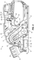
FIG. 4 is a side view of the hand plane ofFIG. 1 with part of the housing hidden for clarity. -
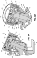
FIG. 5A is a detail view of the depth adjustment mechanism of the hand plane ofFIG. 1 . -
FIG. 5B is another detail view of the depth adjustment mechanism of the hand plane ofFIG. 1 . -
FIG. 6 is a close-up front perspective view of the hand plane ofFIG. 1 . -
FIG. 7 is an exploded perspective view of a front shoe and a chip direction selector. -
FIG. 8 is a detail view of a vacuum or bag connector. -
FIG. 9 is a perspective view of a drivetrain of the hand plane ofFIG. 1 . -
FIGS. 10A-10D illustrate an airflow pathway through the hand plane ofFIG. 1 . - Before any embodiments of the invention are explained in detail, it is to be understood that the invention is not limited in its application to the details of construction and the arrangement of components set forth in the following description or illustrated in the following drawings. The invention is capable of other embodiments and of being practiced or of being carried out in various ways. Also, it is to be understood that the phraseology and terminology used herein is for the purpose of description and should not be regarded as limiting.
-
FIGS. 1-4 depict a hand-held power tool, illustrated as a cordless hand-held planning tool orhand plane 10, according to one embodiment of the present disclosure. Thehand plane 10 includes ahousing 14 formed of two clamshell halves (e.g., aleft clamshell half 14a and aright clamshell half 14b) that ultimately support afront shoe 18 and arear shoe 22. In particular, thefront shoe 18 is movably coupled to abottom front portion 26 of thehand plane 10 and has aplanar bottom surface 30. Therear shoe 22 is coupled to a bottomrear portion 34 of thehand plane 10 and has aplanar bottom surface 38. Furthermore, therear shoe 22 extends into a central portion of thehousing 14 and forms asupport structure 42 for arotating cutting tool 46 and a drivetrain 50 (FIG. 4 ). Therotating cutting tool 46, illustrated as arotating drum 54 supporting at least onecutting blade 58, is disposed between theplanar bottom surface 30 of thefront shoe 18 and theplanar bottom surface 38 of therear shoe 22. Theplanar bottom surface 38 of therear shoe 22 defines a working surface of thehand plane 10, and the rotating cuttingdrum 54 is positioned such that thecutting blade 58 is rotatable through a position approximately tangent to the working surface. A rotational axis A1 of therotating cutting tool 46 is oriented transverse to a longitudinal axis A2 of the hand plane 10 (FIGS. 2 and3 ). Thehand plane 10 further includes ahandle 62 formed by a portion of thehousing 14 and extending along the longitudinal axis A2 of thehand plane 10. Thehandle 62 allows a user to control movement of thehand plane 10 over a workpiece. Aremovable battery pack 66 is coupled to thehandle 62 to provide power to thecordless hand plane 10. In particular, thebattery pack 66 is at least partially received within abattery receptacle 70 that extends along a length direction within thehandle 62. - The
drivetrain 50 includes anelectric motor 74, illustrated as a brushless DC electric motor, operably coupled to therotating cutting tool 46 to provide torque to therotating cutting tool 46. In the illustrated embodiment, theelectric motor 74 is coupled to thesupport structure 42 adjacent therotating cutting tool 46. A rotational axis A3 of theelectric motor 74 is parallel to the rotational axis A1 of therotating cutting tool 46 and, when viewed along a direction parallel to the rotational axis A3 of theelectric motor 74, theelectric motor 74 is disposed above the rotating cutting tool 46 (e.g., further from theplanar bottom surface 38 of the rear shoe 22). A transmission, illustrated as abelt drive 78, couples anoutput 82 of theelectric motor 74 to therotating cutting tool 46. Thebelt drive 78 is disposed outside themain housing 14 and covered by atransmission housing cover 84, which is removably coupled to thehousing 14. In some embodiments, the transmission may be a chain drive, gear drive, or other suitable power transmission mechanism. - With continued reference to
FIG. 4 , theelectric motor 74 is operably coupled to aelectronic control unit 86 adapted to control operation of theelectric motor 74 and thus thehand plane 10. Furthermore, theelectric motor 74 is operably coupled to thebattery pack 66 to receive power therefrom when thebattery pack 66 is received within thebattery receptacle 70. In response to actuation of atrigger mechanism 90, theelectronic control unit 86 provides power from thebattery pack 66 to theelectric motor 74 to activate the electric motor 74 (e.g., initiate rotation of the motor). - In operation, the
hand plane 10 is used to transform a non-planar workpiece (not shown) in a planar workpiece (not shown). To use thehand plane 10, an operator places thehand plane 10 on the workpiece such that theplanar bottom surface 30 of thefront shoe 18 is resting on the non-planar workpiece. An adjustable vertical offset (e.g., perpendicular to theplanar bottom surface 30 of the rear shoe 22) between theplanar bottom surface 30 of thefront shoe 18 and theplanar bottom surface 38 of therear shoe 22 defines a cutting depth of therotating cutting tool 46. In other words, the offset dictates an amount of therotating cutting tool 46 that is exposed to the workpiece. Actuation of thetrigger mechanism 90 by the operator begins rotation of therotating cutting tool 46. As the operator moves thehand plane 10 in a forward direction, therotating cutting tool 46 engages the workpiece to cut or chip material from the workpiece. The cutting or chipping of the workpiece creates a planar surface on the workpiece that is approximately co-planar with the working surface defined by theplanar bottom surface 38 of therear shoe 22. - With reference to
FIGS. 5A, 5B , and6 , adepth adjustment mechanism 94 allows the operator to adjust the cutting depth (i.e., the vertical offset between thefront shoe 18 and the rear shoe 22). Thedepth adjustment mechanism 94 movably couples thefront shoe 18 to thesupport structure 42 of therear shoe 22 to alter the cutting depth. In other words, thedepth adjustment mechanism 94 adjusts the height of thefront shoe 18 relative to therear shoe 22. A larger height difference between the front andrear shoes rotating cutting tool 46 being exposed to the workpiece and, therefore, results in a deeper cutting depth into the workpiece. - The
depth adjustment mechanism 94 includes arotary handle 98 engageable by the operator to move thefront shoe 18 relative to therear shoe 22. Thefront shoe 18 is coupled to therotary handle 98 by aninner shaft 102 that extends through thesupport structure 42 of therear shoe 22. In some embodiments, theinner shaft 102 is integrally formed with thefront shoe 18. In other embodiments theinner shaft 102 is separately formed from thefront shoe 18 and fixedly coupled to thefront shoe 18. For example,FIG. 5A illustrates aninner shaft 102 that is separately formed from thefront shoe 18 and threadedly coupled to thefront shoe 18. Anouter adjustment housing 106 is disposed radially within therotary handle 98 and rotationally fixed to therotary handle 98 via a spline connection. Therefore, rotation of therotary handle 98 imparts equivalent rotation on theouter adjustment housing 106. Theouter adjustment housing 106 is fixed in translation relative to thesupport portion 42. In other words, theouter adjustment housing 106 is capable of rotational motion only. A radiallyinner surface 110 of theouter adjustment housing 106 is threaded. Disposed radially within theouter adjustment housing 106 is aninner adjustment housing 114. Anouter surface 118 of theinner adjustment housing 114 is threaded and engaged with the threadedinner surface 110 of theouter adjustment housing 106. In the illustrated embodiment, a biasingmember 122, such as a compression spring, is engaged with theouter adjustment housing 106 and theinner adjustment housing 114 to decrease backlash between the threads. In other embodiments, the biasingmember 122 may be another type of spring capable of imparting a biasing force on theouter adjustment housing 106 and theinner adjustment housing 114, as will be understood by one of ordinary skill in the art. In yet other embodiments, thedepth adjustment mechanism 94 may not have a biasingmember 122. - The
inner adjustment housing 114 is rotationally fixed to theinner shaft 102 of thefront shoe 18, and thefront shoe 18 is rotationally constrained relative to supportstructure 42. By virtue of the connection to thefront shoe 18, theinner shaft 102 and theinner adjustment housing 114 are rotationally fixed. Therefore, rotation of therotary handle 98 ultimately results in translation of thefront shoe 18 along a longitudinal axis of theinner shaft 102. In the illustrated embodiment, the longitudinal axis of the inner shaft defines a rotational axis of thedepth adjustment mechanism 94. More particularly, rotation of therotary handle 98 imparts rotation to theouter adjustment housing 106, which is axially stationary with respect to thesupport portion 42. Due to theinner adjustment housing 114 and theinner shaft 102 being rotationally fixed but free to move in translation, rotation of theouter adjustment housing 106 relative to theinner adjustment housing 114 causes theinner shaft 102 to translate because of the threaded connection between the outer andinner adjustment housings - With continued reference to
FIGS. 5A, 5B , and6 , thedepth adjustment mechanism 94 of the illustrated embodiment includesindicia 126 to visually indicate to the operator the cutting depth. Thedepth adjustment mechanism 94 also includes adetent mechanism 130 to provide a tactile indication to the operator that thedepth adjustment mechanism 94 has changed between discrete depth values (i.e., cutting depths). Thedetent mechanism 130 includes aspring 134 biasing aball 138 towards anindicator structure 142. Thedetent mechanism 130 is disposed within abottom housing 146 that is secured to thesupport structure 42 of therear shoe 22. Theindicator structure 142 is coupled to therotary handle 98 for co-rotation therewith. In the illustrated embodiment, a spline fit couples theindicator structure 142 to therotary handle 98. The spline fit allows for adjustment of theindicator structure 142 relative to the rotary handle 98 during assembly to calibrate the detent mechanism 130 (e.g., align thedetent mechanism 130 with the discrete depth values and indicia 126). In the illustrated embodiment, theindicator structure 142 is a washer shapedplate having flanges outer flange 154 includes the spline fit. Theindicator structure 142 includes a plurality of circumferentially spacedindentations 158, corresponding in number to the discrete depth values, which theball 138 is biased towards (e.g., by the spring 134). Therefore, as therotary handle 98 is rotated, theball 138 "clicks" into theindentations 158 to indicate a change to the next discrete depth value. Thedepth adjustment mechanism 94 of the illustrated embodiment includes both the indicia 126 (e.g., visual indicators) and the detent mechanism 130 (e.g., tactile indicator). However, in other embodiments, thedepth adjustment mechanism 94 may include one or no mechanism for indicating the cutting depth. - With reference to
FIGS. 4 ,6, and 7 , thefront shoe 18 includes a firstchip ejection port 162 on a first side of the hand plane 10 (e.g., the side of theleft clamshell half 14a) and a secondchip ejection port 166 on a second side of the hand plane 10 (e.g., the side of theright clamshell half 14b), opposite the first side. Thechip ejection ports rotating cutting tool 46 away from therotating cutting tool 46 to ensure that thecutting blade 58 engages the workpiece without interference from previously removed material. Achip direction selector 170 is pivotably supported within thefront shoe 18 to selectively block chips from being discharged through either the firstchip ejection port 162 or the secondchip ejection port 166. - In the illustrated embodiment, the
chip direction selector 170 is fixed within the front shoe 18 (i.e., theselector 170 is non-removable from the front shoe 18). In particular, thechip direction selector 170 is pivotably coupled to thefront shoe 18 via apivot pin 174. Thepivot pin 174 is vertically oriented (i.e., perpendicular to the planar bottom surface 30) within thefront shoe 18. An actuator portion of thechip direction selector 170 extends beyond thefront shoe 18 in a forward direction of thehand plane 10 to allow the operator to pivot theselector 170. With reference toFIG. 7 , thechip direction selector 170 has awedge portion 178. Thepivot pin 174 is located within a centrally locatedaperture 182 of thewedge portion 178. However, one of ordinary skill in the art will understand that the location of theaperture 182 and the size and shape of thewedge portion 178 can change based on the shape of thefront shoe 18, the location of thechip ejection ports chip direction selector 170 includes asecurement mechanism 186 to selectively rotationally secure thechip direction selector 170. For example, thesecurement mechanism 186 may be configured as a spring and ball detent engageable with indentations on thefront shoe 18. Thesecurement mechanism 186 prevents thechip direction selector 170 from inadvertent pivoting movement due to impacts from chips during operation. In other embodiments, thesecurement mechanism 186 may be a protrusion extending from thewedge portion 178 that engages the indentations with an interference fit, rather than a spring and ball detent. - With reference to
FIGS. 6 and8 , theillustrated hand plane 10 includes a vacuum orbag connector 190 to selectively couple a vacuum or a bag (not shown) to either the firstchip ejection port 162 or the secondchip ejection port 166. Theconnector 190 is securable to eitherejection port first ejection port 162. It should be understood that the following description is equally applicable to thesecond ejection port 166. Theconnector 190 allows an operator to secure a vacuum or a bag to theejection port 162 through which the chips are directed by thechip direction selector 170. The vacuum or the bag collects the chips as they exit theejection port 162, ensuring a clean workspace. With reference toFIG. 8 , theconnector 190 includes ahousing 194 having achip entrance 198 that corresponds to theejection port 162 and achip exit 202 to which the vacuum or the bag is securable. - The
housing 194 further includes astationary securement protrusion 206 disposed adjacent thechip entrance 198 and arotatable securement latch 210 disposed above thesecurement protrusion 206. Thesecurement protrusion 206 is shaped to fit within afirst slot 214 in thehousing 14 of the hand plane 10 (FIG. 6 ). In the illustrated embodiment, thesecurement protrusion 206 and thefirst slot 214 are T-shaped in cross-section. Thelatch 210 is shaped to fit within asecond slot 218 in thehousing 14 of thehand plane 10, thereby securing theconnector 190 to thehand plane 10. In the illustrated embodiment, thesecond slot 218 includes a wall 222 (e.g., depth change) that prevents thelatch 210 from moving toward the forward portion of thehand plane 10. Thelatch 210 is rotatable relative to thehousing 194 of theconnector 190 and biased by atorsion spring 226 towards a latched position. To install theconnector 190 on thehand plane 10, the operator moves theconnector 190 along thehousing 14, in a direction from the front towards the rear, with theprotrusion 206 aligned with thefirst slot 214 and thelatch 210 aligned with thesecond slot 218. As thelatch 210 passes thewall 222 of thesecond slot 218, thetorsion spring 226 will bias thelatch 210 into theslot 218. The T-shape of theprotrusion 206 andfirst slot 214 prevents movement of theconnector 190 laterally away from thehousing 14, while engagement of thewall 222 and thelatch 210 prevents movement of theconnector 190 along the length of thehousing 14. To remove theconnector 190, the operator rotates thelatch 210 against the force of thetorsion spring 226 to release thelatch 210 from thewall 222 of thesecond slot 218. Once thelatch 210 is released, the operator slides theconnector 190 towards the front of thehousing 14 to remove theprotrusion 206 from thefirst slot 214. - With reference to
FIGS. 9 and10A-10D , afan 230 is coupled to anoutput 82 of theelectric motor 74 to generate an airflow (arrow inFIGS. 10A-10D ) within thehand plane 10. The airflow is operable to cool components of thehand plane 10 and assist in the removal of chips from thefront shoe 18. In the illustrated embodiment, thefan 230 draws air into thehousing 14 viainlets 234 in theleft clamshell half 14a, adjacent thetransmission housing cover 84. The air is then directed over theelectronic control unit 86 and theelectric motor 74 to cool theelectronic control unit 86 and themotor 74. After the air flows across theelectronic control unit 86, the air enters thesupport structure 42 of therear shoe 22 and is directed toward therotating cutting tool 46. At this point, the air is directed around therotating cutting tool 46 and enjoined with the chipped material to assist in directing the chipped material towards thefront shoe 18 and out of the firstchip ejection port 162 or the secondchip ejection port 166. In the illustrated embodiment, the air flow enters thehand plane 10 through only theleft clamshell half 14a adjacent thebelt drive 78. However, in some embodiments, the airflow may enter thehand plane 10 from the other side or both sides of thehousing 14. - With reference to
FIGS. 1-4 , thetrigger mechanism 90 includes a first or "primary"trigger 238 and a second or "auxiliary"trigger 242. Theauxiliary trigger 242 is disposed on thehousing 14 adjacent theprimary trigger 238 and includes anarcuate surface 246 that interfaces with (e.g., slides against) a correspondingarcuate surface 250 of theprimary trigger 238. Theprimary trigger 238 includes aprojection 254 that is engageable with aswitch 260 coupled to theelectronic control unit 86. Actuation of theswitch 260 results in actuation of theelectric motor 74. Theprimary trigger 238 and theauxiliary trigger 242 are both moveable between a first position and a second position. - In operation, a user grasps the
handle 62 and pivots theauxiliary trigger 242 from the first position toward the second position. By doing so, thearcuate surface 246 of theauxiliary trigger 242 no longer inhibits movement of theprimary trigger 238. At this point, theprimary trigger 238 is moveable between the first position and the second position. Movement of theprimary trigger 238 toward the second position depresses theswitch 260 and ultimately actuates themotor 74. - Although the invention has been described in detail with reference to certain preferred embodiments, variations and modifications exist within the scope and spirit of one or more independent aspects of the invention as described.
- Various features of the invention are set forth in the following claims.
- When used in this specification and claims, the terms "comprises" and "comprising" and variations thereof mean that the specified features, steps or integers are included. The terms are not to be interpreted to exclude the presence of other features, steps or components.
- Representative features are set out in the following clauses, which stand alone or may be combined, in any combination, with one or more features disclosed in the text and/or drawings of the specification.
- 1. A hand-held power tool comprising:
- a housing;
- a first shoe movably coupled to the housing;
- a second shoe fixedly coupled to the housing;
- a rotating cutting tool disposed between the first shoe and the second shoe, the rotating cutting tool configured to engage a workpiece; and
- a depth adjustment mechanism configured to adjust a position of the first shoe relative to the second shoe, the depth adjustment mechanism including
- a rotary handle, and
- an inner shaft, the inner shaft fixedly coupled to the first shoe and threadedly coupled to the rotary handle,
- wherein the first shoe translates relative to the second shoe in response to rotation of the rotary handle.
- 2. The hand-held power tool of clause 1, wherein rotation of the rotary handle in a first direction results in translation of the first shoe in a direction that increases a vertical offset between a bottom surface of the first shoe and a bottom surface of the second shoe, and wherein rotation of the rotary handle in a second direction, opposite the first direction, results in translation of the first shoe in a direction that decreases the vertical offset between the bottom surface of the first shoe and the bottom surface of the second shoe.
- 3. The hand-held power tool of clause 1, wherein the rotary handle is configured to rotate without translating, and wherein the inner shaft is configured to translate without rotating.
- 4. The hand-held power tool of clause 1, wherein the second shoe includes a support structure configured to support the first shoe and the depth adjustment mechanism.
- 5. The hand-held power tool of clause 1, wherein the depth adjustment mechanism includes an outer adjustment housing disposed within the rotary handle, wherein the outer adjustment housing is rotationally fixed to the rotary handle, and wherein a radially inner surface of the outer adjustment housing is threaded.
- 6. The hand-held power tool of clause 5, wherein the depth adjustment mechanism further includes an inner adjustment housing disposed within the outer adjustment housing, wherein the inner adjustment housing is threadedly coupled to the outer adjustment housing and rotationally fixed to the inner shaft.
- 7. The hand-held power tool of clause 1, wherein the depth adjustment mechanism includes a plurality of indicia configured to visually indicate a cutting depth of the hand-held power tool to an operator.
- 8. The hand-held power tool of clause 1, wherein the depth adjustment mechanism includes a detent mechanism configured to provide a tactile indication to an operator that a cutting depth of the hand-held power tool has been changed.
- 9. A hand-held power tool comprising:
- a housing;
- a front shoe movably coupled to the housing, the front shoe including a first chip ejection port and a second chip ejection port;
- a rear shoe fixedly coupled to the housing;
- a rotating cutting tool disposed between the front shoe and the rear shoe, the rotating cutting tool configured to engage a workpiece to remove material from the workpiece; and
- a chip direction selector disposed within the front shoe, the chip direction selector movable between a first position, in which the chip direction selector directs material removed from the workpiece toward the first chip ejection port, and a second position, in which the chip direction selector directs material removed from the workpiece toward the second chip ejection port.
- 10. The hand-held power tool of clause 9, wherein the first chip ejection port is disposed on a first side of the front shoe, and wherein the second chip ejection port is disposed on a second side of the front shoe, the second side of the front shoe being opposite the first side of the front shoe relative to a longitudinal axis of the hand-held power tool.
- 11. The hand-held power tool of clause 9, wherein the chip direction selector is pivotable between the first position and the second position.
- 12. The hand-held power tool of clause 11, wherein the chip direction selector is pivotably coupled to the front shoe by a pivot pin.
- 13. The hand-held power tool of clause 12, wherein the chip direction selector includes a wedge portion to which the pivot pin is coupled and an actuator portion extending from a front end of the wedge portion and beyond the front shoe to be engaged by an operator to be moved between the first position and the second position.
- 14. The hand-held power tool of clause 9, further comprising a securement mechanism disposed between the chip direction selector and the front shoe, wherein the securement mechanism is configured to prevent movement of the chip direction selector due to contact with the material removed from the workpiece.
- 15. A hand-held power tool comprising:
- a housing;
- a front shoe coupled to the housing at a forward end of the housing, the front shoe including a first chip ejection port and a second chip ejection port;
- a rear shoe coupled to the housing at an opposite, rearward end of the housing;
- a rotating cutting tool disposed between the front shoe and the rear shoe, the rotating cutting tool configured to engage a workpiece to remove material from the workpiece;
- an electric motor operably coupled to the rotating cutting tool to rotate the rotating cutting tool; and
- a fan operably coupled to the electric motor, the fan configured to generate an airflow within the housing,
- wherein the airflow is configured to pass over the electric motor to cool the electric motor, and
- wherein the airflow is configured to exit the hand-held power tool through the first chip ejection port or the second chip ejection port.
- 16. The hand-held power tool of clause 15, further comprising an electronic control unit configured to control the electric motor, wherein the airflow passes over the electronic control unit to cool the electronic control unit prior to passing over the electric motor.
- 17. The hand-held power tool of clause 16, wherein, after passing over the electric motor, the airflow is directed around the rotating cutting tool, where the airflow picks up the material removed by the rotating cutting tool and transports it toward the first chip ejection port or the second chip ejection port.
- 18. The hand-held power tool of clause 17, further comprising a chip direction selector disposed within the front shoe, wherein the chip direction selector is configured to direct the material and the airflow toward one of the first chip ejection port or the second chip ejection port.
- 19. The hand-held power tool of clause 15, further comprising a transmission configured to couple the electric motor to the rotating cutting tool.
- 20. The hand-held power tool of clause 19, wherein the transmission is a belt drive.
- 21. A hand-held power tool comprising:
- a housing;
- a front shoe coupled to the housing, the front shoe including a first chip ejection port and a second chip ejection port;
- a rear shoe coupled to the housing;
- a rotating cutting tool disposed between the front shoe and the rear shoe, the rotating cutting tool configured to engage a workpiece to remove material from the workpiece; and
- a connector removably coupled to the housing proximate the first chip ejection port or the second chip ejection port, the connector including
- a chip entrance configured to be in fluid communication with a vacuum or a bag, a securement protrusion engageable with a first slot in the housing, and
- a rotatable latch engageable with a second slot in the housing,
- wherein the connector is configured to direct material removed from the workpiece from the first chip ejection port or the second chip ejection port toward the vacuum or the bag.
- 22. The hand-held power tool of clause 21, wherein the securement protrusion and the first slot are T-shaped in cross-section.
- 23. The hand-held power tool of clause 21, wherein the second slot includes a depth change configured to prevent the rotatable latch from moving along the second slot.
- 24. The hand-held power tool of clause 21, further comprising a spring configured to bias the rotatable latch towards a position in which the rotatable latch is engaged with the second slot.
Claims (15)
- A hand-held power tool comprising:a housing;a first shoe movably coupled to the housing;a second shoe fixedly coupled to the housing;a rotating cutting tool disposed between the first shoe and the second shoe, the rotating cutting tool configured to engage a workpiece; anda depth adjustment mechanism configured to adjust a position of the first shoe relative to the second shoe, the depth adjustment mechanism includinga rotary handle, andan inner shaft, the inner shaft fixedly coupled to the first shoe and threadedly coupled to the rotary handle,wherein the first shoe translates relative to the second shoe in response to rotation of the rotary handle.
- The hand-held power tool of claim 1, wherein:a) rotation of the rotary handle in a first direction results in translation of the first shoe in a direction that increases a vertical offset between a bottom surface of the first shoe and a bottom surface of the second shoe, and wherein rotation of the rotary handle in a second direction, opposite the first direction, results in translation of the first shoe in a direction that decreases the vertical offset between the bottom surface of the first shoe and the bottom surface of the second shoe; and/orb) the rotary handle is configured to rotate without translating, and wherein the inner shaft is configured to translate without rotating; and/orc) the second shoe includes a support structure configured to support the first shoe and the depth adjustment mechanism.
- The hand-held power tool of claim 1 or 2, wherein the depth adjustment mechanism includes an outer adjustment housing disposed within the rotary handle, wherein the outer adjustment housing is rotationally fixed to the rotary handle, and wherein a radially inner surface of the outer adjustment housing is threaded, preferably wherein the depth adjustment mechanism further includes an inner adjustment housing disposed within the outer adjustment housing, wherein the inner adjustment housing is threadedly coupled to the outer adjustment housing and rotationally fixed to the inner shaft.
- The hand-held power tool of any preceding claim, wherein:a) the depth adjustment mechanism includes a plurality of indicia configured to visually indicate a cutting depth of the hand-held power tool to an operator; and/orb) the depth adjustment mechanism includes a detent mechanism configured to provide a tactile indication to an operator that a cutting depth of the hand-held power tool has been changed.
- A hand-held power tool comprising:a housing;a front shoe movably coupled to the housing, the front shoe including a first chip ejection port and a second chip ejection port;a rear shoe fixedly coupled to the housing;a rotating cutting tool disposed between the front shoe and the rear shoe, the rotating cutting tool configured to engage a workpiece to remove material from the workpiece; anda chip direction selector disposed within the front shoe, the chip direction selector movable between a first position, in which the chip direction selector directs material removed from the workpiece toward the first chip ejection port, and a second position, in which the chip direction selector directs material removed from the workpiece toward the second chip ejection port.
- The hand-held power tool of claim 5, wherein the first chip ejection port is disposed on a first side of the front shoe, and wherein the second chip ejection port is disposed on a second side of the front shoe, the second side of the front shoe being opposite the first side of the front shoe relative to a longitudinal axis of the hand-held power tool.
- The hand-held power tool of claim 5 or 6, wherein the chip direction selector is pivotable between the first position and the second position.
- The hand-held power tool of claim 7, wherein the chip direction selector is pivotably coupled to the front shoe by a pivot pin, preferably wherein the chip direction selector includes a wedge portion to which the pivot pin is coupled and an actuator portion extending from a front end of the wedge portion and beyond the front shoe to be engaged by an operator to be moved between the first position and the second position.
- The hand-held power tool of any one of claim 5 to 8, further comprising a securement mechanism disposed between the chip direction selector and the front shoe, wherein the securement mechanism is configured to prevent movement of the chip direction selector due to contact with the material removed from the workpiece.
- A hand-held power tool comprising:a housing;a front shoe coupled to the housing at a forward end of the housing, the front shoe including a first chip ejection port and a second chip ejection port;a rear shoe coupled to the housing at an opposite, rearward end of the housing;a rotating cutting tool disposed between the front shoe and the rear shoe, the rotating cutting tool configured to engage a workpiece to remove material from the workpiece;an electric motor operably coupled to the rotating cutting tool to rotate the rotating cutting tool; anda fan operably coupled to the electric motor, the fan configured to generate an airflow within the housing,wherein the airflow is configured to pass over the electric motor to cool the electric motor, andwherein the airflow is configured to exit the hand-held power tool through the first chip ejection port or the second chip ejection port.
- The hand-held power tool of claim 10, further comprising an electronic control unit configured to control the electric motor, wherein the airflow passes over the electronic control unit to cool the electronic control unit prior to passing over the electric motor.
- The hand-held power tool of claim 11, wherein, after passing over the electric motor, the airflow is directed around the rotating cutting tool, where the airflow picks up the material removed by the rotating cutting tool and transports it toward the first chip ejection port or the second chip ejection port, preferably further comprising a chip direction selector disposed within the front shoe, wherein the chip direction selector is configured to direct the material and the airflow toward one of the first chip ejection port or the second chip ejection port.
- The hand-held power tool of claim 10, 11 or 12, further comprising a transmission configured to couple the electric motor to the rotating cutting tool, preferably wherein the transmission is a belt drive.
- A hand-held power tool comprising:a housing;a front shoe coupled to the housing, the front shoe including a first chip ejection port and a second chip ejection port;a rear shoe coupled to the housing;a rotating cutting tool disposed between the front shoe and the rear shoe, the rotating cutting tool configured to engage a workpiece to remove material from the workpiece; anda connector removably coupled to the housing proximate the first chip ejection port or the second chip ejection port, the connector includinga chip entrance configured to be in fluid communication with a vacuum or a bag, a securement protrusion engageable with a first slot in the housing, anda rotatable latch engageable with a second slot in the housing,wherein the connector is configured to direct material removed from the workpiece from the first chip ejection port or the second chip ejection port toward the vacuum or the bag.
- The hand-held power tool of claim 14:a) wherein the securement protrusion and the first slot are T-shaped in cross-section; and/orb) wherein the second slot includes a depth change configured to prevent the rotatable latch from moving along the second slot; and/orc) further comprising a spring configured to bias the rotatable latch towards a position in which the rotatable latch is engaged with the second slot.
Applications Claiming Priority (1)
| Application Number | Priority Date | Filing Date | Title |
|---|---|---|---|
| US202263334215P | 2022-04-25 | 2022-04-25 |
Publications (1)
| Publication Number | Publication Date |
|---|---|
| EP4292787A1 true EP4292787A1 (en) | 2023-12-20 |
Family
ID=86096055
Family Applications (1)
| Application Number | Title | Priority Date | Filing Date |
|---|---|---|---|
| EP23169078.5A Pending EP4292787A1 (en) | 2022-04-25 | 2023-04-20 | Hand-held planing tool |
Country Status (3)
| Country | Link |
|---|---|
| US (2) | US12589518B2 (en) |
| EP (1) | EP4292787A1 (en) |
| CN (1) | CN220050194U (en) |
Citations (3)
| Publication number | Priority date | Publication date | Assignee | Title |
|---|---|---|---|---|
| EP0042445A1 (en) * | 1980-06-12 | 1981-12-30 | Black & Decker Inc. | Depth of cut adjustment mechanism |
| US4382729A (en) * | 1980-10-02 | 1983-05-10 | Black & Decker Inc. | Depth of cut adjustment mechanism for a power planer |
| US20170129129A1 (en) * | 2014-06-25 | 2017-05-11 | Robert Bosch Gmbh | Portable Machine Tool |
Family Cites Families (371)
| Publication number | Priority date | Publication date | Assignee | Title |
|---|---|---|---|---|
| DE608753C (en) | 1935-01-31 | Albert Hoefer | Hand planer | |
| DE971037C (en) | 1958-11-13 | Reich Maschf Gmbh Karl | Electric hand plane | |
| DE1986781U (en) | 1968-06-06 | Metabowerke K.G. Closs, Rauch a Schnizler, 7440 Nürtingen | Electric hand planes | |
| US3126929A (en) | 1964-03-31 | Power-operated | ||
| DE7804437U1 (en) | 1978-06-15 | 7157 Murrhardt | Plane for reworking the ruts made in the running surface of skis | |
| US1599713A (en) | 1926-09-14 | Combines scraping and brushing machine | ||
| DE187879C (en) | ||||
| US2688348A (en) | 1954-09-07 | Portable power operated planer | ||
| US760074A (en) | 1901-02-04 | 1904-05-17 | William E Lee | Hand-plane. |
| US898793A (en) | 1906-07-28 | 1908-09-15 | William Wilson Scott | Floor-planing tool. |
| US851702A (en) | 1906-08-13 | 1907-04-30 | Vinzenz Spietschka | Rotary dressing device. |
| US1023406A (en) | 1911-12-07 | 1912-04-16 | Bert Ackerman | Rotary rasp. |
| US1090602A (en) | 1913-01-22 | 1914-03-17 | Kerner Mfg Company | Power-operated hand planer or smoother. |
| US1172828A (en) | 1915-07-15 | 1916-02-22 | Joseph G Osgood | Power-plane. |
| US1182745A (en) | 1915-10-05 | 1916-05-09 | William A Bridges | Planer. |
| US1243460A (en) | 1915-12-09 | 1917-10-16 | Gulbransen Dickinson Company | Portable planing-machine. |
| US1270023A (en) | 1917-04-26 | 1918-06-18 | George F Dyer | Jack-plane. |
| US1272196A (en) | 1918-01-02 | 1918-07-09 | Edward C Broward | Portable hand-planer. |
| US1281207A (en) | 1918-01-07 | 1918-10-08 | John M Richens | Hand-planer. |
| US1337350A (en) | 1918-03-14 | 1920-04-20 | Universal Planer Company Inc | Portable planing-machine |
| US1279488A (en) | 1918-04-13 | 1918-09-17 | Internat Marine Planer Inc | Portable hand-planer. |
| US1366389A (en) | 1918-04-17 | 1921-01-25 | Turbine Air Tool Company | Portable tool |
| US1346215A (en) | 1918-04-17 | 1920-07-13 | Turbine Air Tool Company | Knife-securing means for cutter-heads |
| US1296911A (en) | 1918-07-23 | 1919-03-11 | Thomas H Spencer | Portable hand-planer. |
| US1396762A (en) | 1918-11-27 | 1921-11-15 | Turbine Air Tool Company | Rotor for cutter-heads |
| DE355060C (en) | 1919-02-19 | 1922-06-20 | Josef Kaelin | Tool shaft for milling and planing work for wood |
| US1357985A (en) | 1919-06-16 | 1920-11-09 | Impalea Vito | Gage attachment for planes |
| US1426739A (en) | 1919-08-07 | 1922-08-22 | Luster Jordan Company | Hand planer |
| US1339172A (en) | 1919-09-06 | 1920-05-04 | Thomas J Dempsey | Surface trimming or planing machine |
| US1392543A (en) | 1921-04-09 | 1921-10-04 | Isaac A Watrous | Electrically-operated machine for scraping irregular wooden surfaces |
| US1679562A (en) * | 1923-07-19 | 1928-08-07 | Alex A Clarke | Portable electric jointer |
| US1527785A (en) | 1924-01-10 | 1925-02-24 | Ray L Carter | Plane |
| US1544667A (en) | 1924-04-30 | 1925-07-07 | Reuben C Loughner | Power plane |
| US1614783A (en) | 1924-11-03 | 1927-01-18 | Premier Grand Piano Corp | Portable rotary planer |
| US1641645A (en) | 1925-07-20 | 1927-09-06 | Skolnik Patents Inc | Power plane |
| US1727383A (en) | 1925-09-15 | 1929-09-10 | Simonides Bruno | Portable electrically-driven machine for planing, grinding, drilling, milling, sawing, and other operations |
| US1732594A (en) | 1926-11-12 | 1929-10-22 | Wood-sttbfaciua machine | |
| US1706157A (en) | 1927-05-13 | 1929-03-19 | Walter H Hannah | Power-driven plane |
| US1736965A (en) | 1928-11-03 | 1929-11-26 | R L Carter Company Inc | Woodwork plow |
| US1775430A (en) | 1929-12-03 | 1930-09-09 | Hibbs Russell Rust | Wood-grooving machine |
| US1760818A (en) | 1929-12-10 | 1930-05-27 | Daderko Michael | Portable hand-operated power-driven plane |
| US1812755A (en) | 1930-05-02 | 1931-06-30 | Frank M Quinsler | Power driven plane |
| US1900336A (en) | 1931-02-28 | 1933-03-07 | John J Egan | Woodworking machinery |
| US1929504A (en) * | 1932-07-29 | 1933-10-10 | Abraham H Lavietes | Carpenter's plane |
| US1980056A (en) | 1933-02-08 | 1934-11-06 | Hans U Hedeby | Power actuated hand plane |
| US2085603A (en) | 1934-10-26 | 1937-06-29 | Black & Decker Mfg Co | Manually portable power-driven rotary planer |
| US2030520A (en) | 1935-06-06 | 1936-02-11 | Heimsath Gus | Power plane |
| US2393463A (en) | 1943-04-08 | 1946-01-22 | Albert Sherman | Milling tool |
| US2395268A (en) | 1943-09-09 | 1946-02-19 | Clarence E Goodridge | Hand plane |
| US2395158A (en) | 1943-12-18 | 1946-02-19 | Goldie M Ball | Power-driven hand plane |
| CH247061A (en) | 1946-04-06 | 1947-02-15 | Schneider Max | Hand planer equipment. |
| US2544098A (en) | 1946-04-17 | 1951-03-06 | Libby Henry Thomas | Power actuated hand plane |
| US2562832A (en) | 1948-04-30 | 1951-07-31 | Edwin J Strandberg | Planer attachment for portable power sources |
| US2600859A (en) | 1948-06-22 | 1952-06-17 | Drysdale Robert | Hand electric plane |
| US2583637A (en) | 1948-07-02 | 1952-01-29 | William F Draper | Portable electric planer |
| BE489127A (en) | 1948-10-01 | |||
| US2600279A (en) | 1949-03-24 | 1952-06-10 | Henry A Spitzley | Portable power-driven planer |
| BE489167A (en) | 1949-04-01 | |||
| DE812209C (en) | 1949-07-15 | 1951-11-19 | Julius Kottmann | Gerb- and plastering planes for processing curved surfaces, in particular wooden container walls o. |
| DE890419C (en) | 1949-10-30 | 1953-09-17 | Karl M Reich Fa | Electrically powered portable planer |
| DE817810C (en) | 1949-11-20 | 1951-10-22 | Max Baumgartner | Hand planer |
| DE823039C (en) | 1949-12-01 | 1951-11-29 | Schanbacher & Ebner | Hand plane with rotating planer knife |
| DE869264C (en) | 1950-02-22 | 1953-03-02 | Ferdinand Baier | Electric barrel planer |
| DE823516C (en) | 1950-02-22 | 1951-12-03 | Richard Knecht | Planing and grooving machine for barrel processing |
| DE844966C (en) | 1950-10-01 | 1952-07-28 | Licentia Gmbh | Electrically powered wooden hand plane |
| US2719553A (en) | 1951-05-22 | 1955-10-04 | Lillie Ballard | Portable power plane |
| DE919197C (en) | 1951-06-17 | 1954-10-14 | Karl Stelzl | Planing machine, especially for floor processing |
| DE873134C (en) | 1951-10-30 | 1953-04-09 | Ludwig Roemer K G | Hand plane with an exchangeable planer head driven by an electric motor |
| US2672172A (en) | 1951-12-04 | 1954-03-16 | Stanley Works | Electric plane |
| DE890863C (en) | 1951-12-20 | 1953-09-24 | Mafell Maschinenfabrik Inh Dip | Electric motor driven wood planing or milling machine with a base plate that can be placed on the workpiece |
| DE929928C (en) | 1952-02-08 | 1955-07-07 | Mafell Maschinenfabrik Inh Dip | Electric motor driven woodworking machine |
| US2746499A (en) | 1952-05-03 | 1956-05-22 | Leo O Greeley | Powered hand plane |
| US2718248A (en) | 1952-08-11 | 1955-09-20 | Whitehead Stamping Company | Portable motor driven plane |
| US2675034A (en) | 1953-02-27 | 1954-04-13 | Minnesota & Ontario Paper Co | Gaining apparatus |
| US2788810A (en) | 1953-07-25 | 1957-04-16 | Charles E Jones | Woodworking attachment for drill motors |
| US2707502A (en) | 1953-10-20 | 1955-05-03 | Anctil Joseph Noel | Double acting portable power planing device |
| US2805692A (en) | 1955-03-07 | 1957-09-10 | Edward O Thompson | Planer for boats |
| US2774399A (en) | 1955-03-15 | 1956-12-18 | Porter Cable Machine Co | Power operated wood plane with chip and shaving discharge means |
| US2771104A (en) | 1955-06-03 | 1956-11-20 | Raymond J Saxe | Planer attachment for electric drills or the like |
| US2771105A (en) | 1955-09-14 | 1956-11-20 | Rotex Company | Power driven hand tools |
| US2871897A (en) | 1955-10-28 | 1959-02-03 | Remington Arms Co Inc | Power plane |
| DE1007988B (en) | 1955-11-26 | 1957-05-09 | Mafell Maschinenfabrik Inh Dip | Belt tensioning device on portable electric hand tools, in particular planing tools |
| NL212430A (en) | 1955-11-29 | |||
| DE1739720U (en) | 1956-01-18 | 1957-02-14 | Ludwig Roemer K G | ELECTRIC MANUAL PLANER. |
| US2805696A (en) | 1956-04-19 | 1957-09-10 | Edward O Thompson | Attachment for planer for boats |
| DE1030988B (en) | 1956-04-20 | 1958-05-29 | Lutz Kg Maschf Eugen | Device for adjusting the chip limiter on hand planes with a rotating tool with face and face cutting edges |
| DE1080764B (en) | 1956-04-25 | 1960-04-28 | Reich Maschf Gmbh Karl | Chip removal on hand planing machines |
| US2903030A (en) | 1956-05-01 | 1959-09-08 | Robert E Ferguson | Router plane |
| US2894549A (en) | 1956-06-15 | 1959-07-14 | Willis F Garland | Portable power plane |
| US2893454A (en) | 1957-05-07 | 1959-07-07 | Millers Falls Co | Portable power planer with outboard support for cutter |
| DE1790994U (en) | 1958-12-01 | 1959-06-25 | Franz Lindner | ELECTRIC MANUAL PLANER. |
| US2984270A (en) | 1959-09-09 | 1961-05-16 | Simmonds Aerocessories Ltd | Cutting and abrading tools |
| DE1860337U (en) | 1962-08-09 | 1962-10-18 | Metabowerke Kg | ELECTRIC PLANE. |
| DE1870186U (en) | 1963-02-13 | 1963-04-11 | Lutz Kg Eugen | ELECTRICALLY DRIVEN, HAND-HELD SURFACE PLANING MACHINE. |
| US3207195A (en) | 1963-02-13 | 1965-09-21 | Wen Products Inc | Electric hand plane |
| US3253624A (en) | 1964-06-15 | 1966-05-31 | Singer Co | Portable power-operated block planers |
| DE1943624U (en) | 1966-04-23 | 1966-08-04 | Scheer & Cie C F | HAND PLANING MACHINE. |
| DE1946172U (en) | 1966-06-22 | 1966-09-15 | Metabowerke Kg | MOTOR-DRIVEN HAND PLANE. |
| DE1980401U (en) | 1966-07-16 | 1968-03-07 | Licentia Gmbh | MOTOR-DRIVEN HAND PLANE. |
| US3407857A (en) | 1966-12-30 | 1968-10-29 | Rockwell Mfg Co | Plane |
| US3443613A (en) | 1967-04-13 | 1969-05-13 | Mc Graw Edison Co | Power planer |
| DE1977995U (en) | 1967-11-06 | 1968-02-01 | Gotthold Haffner Fa | ELECTRIC PLANE. |
| GB1217999A (en) | 1968-04-29 | 1971-01-06 | Reliance Exp Company Proprieta | Improvements in or relating to wood-working machines |
| DE1994146U (en) | 1968-05-06 | 1968-09-19 | Alfred Stoehr | HEIGHT-ADJUSTABLE SIDE STOP DEVICE FOR MOTOR-DRIVEN PLANES. |
| CH507072A (en) | 1969-04-02 | 1971-05-15 | Hebor Sa | Hand planer |
| DE6923308U (en) | 1969-06-11 | 1969-10-23 | Mey Kg Maschf Mafell | PLANE WITH FOLDING DEPTH STOP |
| DE6923397U (en) | 1969-06-12 | 1969-10-16 | Mey Kg Maschf Mafell | PLANES, IN PARTICULAR HAND PLANES WITH ADJUSTMENT DEVICE |
| DE7013796U (en) | 1970-04-15 | 1970-07-30 | Lutz Kg Maschf Eugen | HAND PLANE. |
| DE2018575A1 (en) | 1970-04-17 | 1971-10-28 | Eugen Lutz KG Maschinenfabrik, 7131 Lomersheim | Electric hand plane |
| DE7021297U (en) | 1970-06-06 | 1970-11-05 | Licentia Gmbh | PLANE WITH AN ELECTRIC MOTOR ENCLOSED IN AN ENGINE CASE. |
| DE7021298U (en) | 1970-06-06 | 1970-11-05 | Licentia Gmbh | ELECTRIC DRIVEN HAND PLANE WITH A BEARING SHIELD ATTACHED TO THE HOUSING. |
| DE7131774U (en) | 1971-08-19 | 1975-05-07 | Reich K Maschinenfabrik Gmbh | Housing for hand machine |
| DE2141584A1 (en) | 1971-08-19 | 1973-03-01 | Reich Maschf Gmbh Karl | HOUSING FOR HAND MACHINE |
| DE2316199A1 (en) | 1973-03-31 | 1974-10-10 | Gerhard Suess | PLANE KNIVES |
| DE2445233A1 (en) | 1974-09-21 | 1976-04-08 | Metabowerke Kg | Hand plane with motor drive - has blade shaft near end of guide face where the housing ends |
| DE2552484A1 (en) | 1975-11-22 | 1977-05-26 | Helmut Meyer | MACHINE FOR THE MACHINING OF SURFACES |
| US4066111A (en) | 1976-10-12 | 1978-01-03 | The Singer Company | Cutter head assembly for power planers |
| DE7701074U1 (en) | 1977-01-15 | 1977-06-08 | C.F. Scheer & Cie Gmbh & Co, 7000 Stuttgart | Motorized hand plane |
| DE2743313A1 (en) | 1977-09-27 | 1979-04-05 | Drehtainer Container Tech | MACHINE FOR THE MACHINING OF SURFACES |
| DE2806822C2 (en) | 1978-02-17 | 1980-04-17 | Karl M. Reich, Maschinenfabrik Gmbh, 7440 Nuertingen | Hand planer |
| DE2811669C2 (en) | 1978-03-17 | 1983-11-17 | Karl M. Reich Maschinenfabrik GmbH, 7440 Nürtingen | Planer head with reversible knives |
| IT1099459B (en) | 1978-09-08 | 1985-09-18 | Star Utensili Elett | CUTTING GROUP FOR ELECTRIC PLANERS |
| DE2939598A1 (en) | 1979-09-29 | 1981-04-09 | Robert Bosch Gmbh, 7000 Stuttgart | HAND-MADE ELECTRIC PLANER |
| DE7934812U1 (en) | 1979-12-11 | 1981-05-27 | Robert Bosch Gmbh, 7000 Stuttgart | Electric motor-driven planer that can be operated by hand |
| DE3069062D1 (en) | 1980-06-12 | 1984-10-04 | Black & Decker Inc | Depth of cut adjustment mechanism |
| DE3024561A1 (en) | 1980-06-28 | 1982-01-21 | Robert Bosch Gmbh, 7000 Stuttgart | HAND MACHINE TOOL WITH ELECTRIC MOTOR DRIVE |
| DE3025797A1 (en) | 1980-07-08 | 1982-02-04 | Robert Bosch Gmbh, 7000 Stuttgart | HAND MACHINE TOOL WITH AN ADJUSTING DEVICE FOR THE TOOL |
| EP0044354B1 (en) | 1980-07-23 | 1984-12-05 | Black & Decker Inc. | Combination guard and rabbeting depth gauge associated with power planer |
| SE421506B (en) | 1980-08-05 | 1982-01-04 | Gunnar Harry Lindkvist | ELECTRICAL MOVEMENT |
| JPS5731501A (en) | 1980-08-05 | 1982-02-20 | Hitachi Koki Kk | Preventive device for horizontal vibration of portable power tool with sliding base |
| EP0048304B1 (en) | 1980-09-24 | 1984-12-19 | Black & Decker Inc. | Depth of cut adjustment mechanism for a power planer |
| EP0048303B1 (en) | 1980-10-07 | 1985-06-26 | Black & Decker Inc. | Cutterhead for a power planer |
| US4363343A (en) | 1980-09-24 | 1982-12-14 | Black & Decker Inc. | Combination guard and rabbeting depth gauge associated with power planer |
| DE3109361A1 (en) | 1981-03-12 | 1982-10-21 | C.F. Scheer & Cie Gmbh & Co, 7000 Stuttgart | Motor-operatable portable plane |
| US4433710A (en) | 1981-10-28 | 1984-02-28 | Posta Antonio D | Power planing tool |
| USD277451S (en) | 1982-04-29 | 1985-02-05 | Black & Decker Inc. | Cordless jig saw |
| DE3239152A1 (en) | 1982-10-22 | 1984-04-26 | Robert Bosch Gmbh, 7000 Stuttgart | KNIFE ROLLER FOR A MOTORIZED PLANER |
| DE3300753A1 (en) | 1983-01-12 | 1984-07-12 | Robert Bosch Gmbh, 7000 Stuttgart | HAND PLANER, IN PARTICULAR DESIGNED AS ELECTRIC HAND MACHINE TOOL |
| DE8302890U1 (en) | 1983-02-03 | 1983-06-01 | Black & Decker, Inc., 19711 Newark, Del. | POWERED PLANER |
| US4492260A (en) | 1983-04-14 | 1985-01-08 | Carl Whiteford | Woodworking plane |
| DE3318745C2 (en) | 1983-05-24 | 1986-12-04 | Eugen Lutz GmbH u. Co Maschinenfabrik, 7130 Mühlacker | Planing machine, in particular hand planer |
| EP0126283B1 (en) | 1983-05-24 | 1989-12-20 | Black & Decker Overseas AG | Guiding means for a hand planer |
| DE3464022D1 (en) | 1983-05-24 | 1987-07-09 | Lutz Eugen & Co | Planing tool and profile cutter suitable therefor |
| EP0126285B1 (en) | 1983-05-24 | 1986-12-30 | Eugen Lutz + Co. | Portable power planer |
| DE3322962C2 (en) | 1983-06-25 | 1986-01-09 | Eugen Lutz GmbH u. Co Maschinenfabrik, 7130 Mühlacker | Chip thickness limiter for electric motor-operated hand planers or the like. |
| DE8323095U1 (en) | 1983-08-11 | 1983-12-15 | Black & Decker, Inc. (eine Gesellschaft n.d.Ges.d. Staates Delaware), 19711 Newark, Del. | DEVICE FOR ADJUSTING THE PLANE DEPTH ON A PORTABLE, POWERTRAINED PLANER |
| DE8323459U1 (en) | 1983-08-16 | 1983-11-24 | Geier, Franz, 8056 Eichenried | Device for processing surfaces made of mortar, masonry, concrete, wood or the like. |
| DE8324322U1 (en) | 1983-08-24 | 1985-05-15 | Schinko, Franz, 7103 Schwaigern | Planing tool for processing components made of wood or wood-like material |
| DE3341219A1 (en) | 1983-11-14 | 1985-05-30 | Licentia Patent-Verwaltungs-Gmbh, 6000 Frankfurt | Device for setting the planing depth in a portable power planer |
| DE3341224A1 (en) | 1983-11-14 | 1985-05-30 | Licentia Patent-Verwaltungs-Gmbh, 6000 Frankfurt | Device for setting the planing depth in a portable power planer |
| DE3341329A1 (en) | 1983-11-15 | 1985-05-23 | Licentia Patent-Verwaltungs-Gmbh, 6000 Frankfurt | Device for a portable power planer for guiding workpieces |
| DE3403092C2 (en) | 1984-01-30 | 1987-05-14 | Günther 7809 Denzlingen Böhler | Planer |
| DE3406728A1 (en) | 1984-02-24 | 1985-08-29 | Karl M. Reich Maschinenfabrik GmbH, 7440 Nürtingen | HAND PLANER |
| DE3429177A1 (en) | 1984-08-08 | 1986-02-20 | Günter 3061 Ahnsen Schilling | Surface planing attachment for portable electric planing machines |
| DE3441943A1 (en) | 1984-11-16 | 1986-05-28 | Licentia Patent-Verwaltungs-Gmbh, 6000 Frankfurt | Portable electric plane |
| DE3520526A1 (en) | 1985-06-07 | 1986-12-11 | Eugen Lutz GmbH u. Co Maschinenfabrik, 7130 Mühlacker | Guide device for a portable planer operated by electric motor |
| DE3525296A1 (en) | 1985-07-16 | 1987-01-29 | Georg Aigner | FASTENING DEVICE FOR WOODWORKING MACHINES, IN PARTICULAR PLANING MACHINES |
| DE8525591U1 (en) | 1985-09-07 | 1986-03-27 | Licentia Patent-Verwaltungs-Gmbh, 6000 Frankfurt | Cutting knife set for electrically powered hand planes |
| DE3531996A1 (en) | 1985-09-07 | 1987-03-19 | Licentia Gmbh | Cutting-blade set for electrically driven portable planers |
| DE8525705U1 (en) | 1985-09-10 | 1985-11-07 | Licentia Patent-Verwaltungs-Gmbh, 6000 Frankfurt | Reversible knife for electrically powered hand planes |
| DE8527236U1 (en) | 1985-09-24 | 1985-11-14 | Licentia Patent-Verwaltungs-Gmbh, 6000 Frankfurt | Cover cap for the rebate face of the cutter head of an electrically powered hand plane |
| DE3542263A1 (en) | 1985-11-29 | 1987-06-04 | Festo Kg | Portable planer |
| DE3542466A1 (en) | 1985-11-30 | 1987-06-04 | Licentia Gmbh | Portable planer driven by means of an electric motor |
| DE3600882A1 (en) | 1986-01-15 | 1987-07-16 | Helmut Ebertseder | Apparatus for holding a hand plane with an electric motor-driven knife |
| DE8602072U1 (en) | 1986-01-28 | 1986-06-05 | Krämer, Günter, 5900 Siegen | Thickness and dressing device in connection with a drill stand and a one-hand electric planer |
| DE3606830A1 (en) | 1986-03-03 | 1987-09-10 | Rainer Bachmann | Electric plane |
| US4693648A (en) | 1986-06-19 | 1987-09-15 | The Singer Company | Depth of cut adjusting mechanism |
| DE3621240A1 (en) | 1986-06-25 | 1988-01-07 | Festo Kg | Powered hand tool |
| DE3621359C2 (en) | 1986-06-26 | 1994-05-05 | Black & Decker Inc | Knife roller for a power-driven planer |
| DE8619361U1 (en) | 1986-07-18 | 1986-09-25 | Mafell Maschinenfabrik Rudolf Mey GmbH & Co KG, 7238 Oberndorf | Hand plane |
| DE8631998U1 (en) | 1986-11-28 | 1987-01-22 | Festo KG, 7300 Esslingen | Hand planer |
| ATE43808T1 (en) | 1987-02-07 | 1989-06-15 | Festo Kg | HAND PLANING MACHINE. |
| DE8703839U1 (en) | 1987-03-14 | 1987-04-23 | Festo KG, 7300 Esslingen | Device for planing workpieces |
| DE8708512U1 (en) | 1987-06-19 | 1987-08-06 | Festo KG, 7300 Esslingen | Hand planer |
| DE8714027U1 (en) | 1987-10-20 | 1987-12-10 | Licentia Patent-Verwaltungs-Gmbh, 6000 Frankfurt | Double-guided parallel and angle stop for hand planes |
| DE8809892U1 (en) | 1988-08-03 | 1989-12-07 | Robert Bosch Gmbh, 7000 Stuttgart | Housing for a hand plane |
| CH678032A5 (en) | 1989-03-21 | 1991-07-31 | Andre Casal | |
| AT390909B (en) | 1989-03-22 | 1990-07-25 | Walke Paul | ELECTRICALLY OPERATED SINGLE-HANDED PLANER |
| DE8906895U1 (en) | 1989-06-06 | 1989-07-20 | Mafell Maschinenfabrik Rudolf Mey GmbH & Co KG, 7238 Oberndorf | Electric planer |
| US5063979A (en) | 1989-12-01 | 1991-11-12 | Johnson Joe C | Acu-planer attachment |
| US5140778A (en) | 1990-02-14 | 1992-08-25 | Louis Carruth | Support and stop for hand held sander to control depth and angle of cut |
| DE4007030A1 (en) | 1990-03-02 | 1991-09-05 | Black & Decker Inc | POWER-DRIVEN MACHINE TOOL WITH A ROTATING DRIVE |
| US5066177A (en) | 1990-12-10 | 1991-11-19 | Brown Jr John H | Attachment to a portable power planar |
| NL9002865A (en) | 1990-12-21 | 1992-07-16 | Emerson Electric Co | PLAN WITH IMPROVED BEARING. |
| US5176478A (en) | 1991-03-26 | 1993-01-05 | Mattias Munch | Fiberglass planing machine |
| DE4117196C2 (en) | 1991-05-27 | 1998-11-12 | Gerhard Fetzer | Hand plane with frame |
| JP3098801B2 (en) | 1991-06-27 | 2000-10-16 | 松下電工株式会社 | Electric circular saw |
| DE4134768A1 (en) | 1991-10-22 | 1993-04-29 | Bosch Gmbh Robert | HAND PLANER |
| US5146959A (en) | 1991-11-12 | 1992-09-15 | Terrell Noel E | Power plane support apparatus |
| DE4137623A1 (en) | 1991-11-15 | 1993-05-19 | Bosch Gmbh Robert | HAND PLANER WITH ROTATING KNIFE CARRIER |
| DE4143151A1 (en) | 1991-12-28 | 1993-07-01 | Bosch Gmbh Robert | ROCKER PLANE |
| DE4204775C2 (en) * | 1992-02-18 | 1993-12-02 | Bosch Gmbh Robert | Electric planer with depth adjustment device |
| DE4212293A1 (en) | 1992-04-11 | 1993-10-14 | Metabowerke Kg | Hand operated electric plane - has roller cutter shaped like frustum of cone revolving on inclined axle with respect to level sole plate |
| JP3188027B2 (en) | 1992-05-01 | 2001-07-16 | 株式会社名南製作所 | Rotating plane |
| DE4227071A1 (en) | 1992-08-17 | 1994-02-24 | Reich Maschf Gmbh Karl | Stop device for edge router |
| DE4310280C2 (en) | 1993-03-30 | 2001-06-28 | Festo Ag & Co | Machine tool, in particular hand machine tool, with a chip ejection part |
| DE4310297A1 (en) | 1993-03-30 | 1994-10-06 | Festo Kg | Hand planer |
| DE4310271A1 (en) | 1993-03-30 | 1994-10-06 | Festo Kg | Hand planer |
| DE4310270A1 (en) | 1993-03-30 | 1994-10-06 | Festo Kg | Hand planer |
| DE4318973A1 (en) | 1993-06-08 | 1994-12-15 | Holger Fritzlar | Hand-guided electric planing machine |
| DE4332281A1 (en) | 1993-09-23 | 1995-03-30 | Weinig Michael Ag | Pressing device for machines for processing workpieces made of wood, plastic and the like |
| DE9403695U1 (en) | 1994-03-04 | 1994-05-19 | Karl M. Reich Maschinenfabrik GmbH, 72622 Nürtingen | Knife shaft for planing machines |
| US5463816A (en) | 1994-05-10 | 1995-11-07 | Ryobi North America | Portable planer with adjustable chip deflector |
| US5522684A (en) | 1994-05-11 | 1996-06-04 | Heck; Philip | Chamfer cutting tool |
| US5423642A (en) | 1994-05-11 | 1995-06-13 | Heck; Philip | Chamfer cutting tool |
| JP2912168B2 (en) | 1994-10-18 | 1999-06-28 | リョービ株式会社 | Electric planer with chip discharge mechanism |
| JP2740129B2 (en) | 1994-10-27 | 1998-04-15 | リョービ株式会社 | Plane with guide ruler fixing mechanism |
| CN2265879Y (en) | 1994-10-28 | 1997-10-29 | 柳花 | Multifunctional portable electric plane |
| USD375439S (en) | 1994-12-27 | 1996-11-12 | Makita Corporation | Cordless circular saw |
| DE19502977B4 (en) | 1995-01-31 | 2006-03-16 | Robert Bosch Gmbh | Hand planer, in particular electric powered hand planer |
| DE19512262C2 (en) | 1995-03-24 | 2003-07-31 | Black & Decker Inc | Hand-held, motor-driven planer |
| JP3151132B2 (en) | 1995-08-11 | 2001-04-03 | 重雄 西井 | Wood cutting equipment |
| DE19536559A1 (en) | 1995-10-02 | 1997-04-03 | Bosch Gmbh Robert | Planing machine, in particular hand planing machine |
| DE19543992C1 (en) | 1995-11-25 | 1997-04-17 | Metabowerke Kg | Motorized hand tool |
| DE29519383U1 (en) | 1995-12-07 | 1996-01-25 | Birke, Helmut, 95233 Helmbrechts | Hand planer |
| CN2243371Y (en) | 1995-12-16 | 1996-12-25 | 赵水华 | Electric edge plane |
| DE19605445C1 (en) | 1996-02-15 | 1997-02-27 | Mai Roland Dipl Ing Fh | Guide for portable power tool |
| DE29604011U1 (en) | 1996-02-26 | 1996-04-25 | Bauwerkzeuge GmbH, 98587 Unterschönau | Device on surface grinding machines for setting the milling depth |
| DE29604292U1 (en) | 1996-03-08 | 1996-04-25 | Robert Bosch Gmbh, 70469 Stuttgart | Hand planer |
| DE19628416A1 (en) | 1996-07-12 | 1998-01-15 | Wolfgang Breier | Planing bottom device for electric hand=held planing machine |
| US5856715A (en) | 1996-12-13 | 1999-01-05 | Ryobi North America, Inc. | Portable electrical power tool having a rare earth permanent magnet motor |
| US5778950A (en) | 1997-01-31 | 1998-07-14 | Wrightman; Ronald A. | Planer attachment |
| DE19704688C1 (en) | 1997-02-07 | 1998-08-06 | Elias Lebessis | Universal cutting device |
| DE19713845B4 (en) | 1997-04-04 | 2005-08-18 | Robert Bosch Gmbh | Hand plane with motor drive |
| DE19717701B4 (en) | 1997-04-26 | 2006-01-12 | Robert Bosch Gmbh | Portable planer |
| DE19717706A1 (en) | 1997-04-26 | 1998-10-29 | Bosch Gmbh Robert | Hand planer |
| IT1293358B1 (en) | 1997-05-12 | 1999-02-25 | Ezio Trevisiol | ELECTROMANUAL SANDING PLANER |
| USD400073S (en) | 1997-06-25 | 1998-10-27 | Makita Corporation | Portable electric belt sander |
| CN2309933Y (en) | 1997-10-23 | 1999-03-10 | 曾立新 | Mutli-function hand-operation electric shape-edge shaver |
| DE19832005B4 (en) | 1998-07-16 | 2011-08-11 | Robert Bosch GmbH, 70469 | Portable planer |
| DE29812699U1 (en) | 1998-07-16 | 1999-12-02 | Robert Bosch Gmbh, 70469 Stuttgart | Hand planer |
| DE19835725B4 (en) | 1998-08-07 | 2016-08-04 | Robert Bosch Gmbh | planer head |
| DE19835724B4 (en) | 1998-08-07 | 2007-04-26 | Robert Bosch Gmbh | planer head |
| DE19837029B4 (en) | 1998-08-14 | 2007-02-15 | Scintilla Ag | planer head |
| EP0993919A3 (en) | 1998-10-07 | 2005-10-26 | Precision Tools Limited Exakt | Hand operated multi purpose power tool |
| DE29820243U1 (en) | 1998-11-12 | 2000-03-23 | Robert Bosch Gmbh, 70469 Stuttgart | Hand planer |
| DE19853374B4 (en) | 1998-11-19 | 2007-06-21 | Robert Bosch Gmbh | Portable planer |
| DE19856278A1 (en) | 1998-12-07 | 2000-06-08 | Bosch Gmbh Robert | Plane iron for planing machine, especially hand-guided plane for wood machining, has concave circular or elliptical blade formed at edge of curved aperture in base body |
| GB9828581D0 (en) | 1998-12-23 | 1999-02-17 | Black & Decker Inc | Cartridge |
| GB9828579D0 (en) | 1998-12-23 | 1999-02-17 | Black & Decker Inc | Power tool |
| CN2361447Y (en) | 1999-03-17 | 2000-02-02 | 吴树勇 | Multi-functional combined hand electric plane |
| CH693327A5 (en) | 1999-04-20 | 2003-06-13 | Hebor Sa | Level plane for finishing ends of wooden panels |
| DE19931118B4 (en) | 1999-07-06 | 2005-11-24 | Metabowerke Gmbh | Motorized hand tool |
| ATE231663T1 (en) | 1999-09-01 | 2003-02-15 | Ramachandran Ramarathnam | ELECTRICAL HAND TOOLS |
| CN2392655Y (en) | 1999-10-09 | 2000-08-23 | 苏州太湖企业有限公司 | Cutting-depth regulating device for electric plane |
| DE20001808U1 (en) | 2000-02-02 | 2001-06-13 | Metabowerke GmbH & Co, 72622 Nürtingen | Cutting hand tool |
| DE10035560A1 (en) | 2000-07-21 | 2002-01-31 | Bosch Gmbh Robert | Hand-operated power tool |
| DE10035559A1 (en) | 2000-07-21 | 2002-01-31 | Bosch Gmbh Robert | Electric hand held tool for milling or planing wood has a surface sole plate separated vertically from the cutting tool by the depth of cut required. |
| CN2431093Y (en) | 2000-07-27 | 2001-05-23 | 苏州太湖企业有限公司 | Air groove scrap remover for planing knife of electric planer |
| CN2437467Y (en) | 2000-08-28 | 2001-07-04 | 杭州东方实业有限公司 | Fast blade mounted inclined blade base of electric planer |
| CN2443815Y (en) | 2000-08-28 | 2001-08-22 | 杭州东方实业有限公司 | Electric plane with foot-rest |
| DE10053548A1 (en) | 2000-10-27 | 2002-05-16 | Herbert K Wolf | Electrically driven hand-held planing machine for planing materials comprises a rotating planing block with a height-adjustable front bearing surface |
| WO2002062541A1 (en) | 2001-02-08 | 2002-08-15 | Peter Zanki | Blade guard |
| US6601621B2 (en) | 2001-04-18 | 2003-08-05 | Black & Decker Inc. | Portable Power Planer |
| US7458402B2 (en) | 2001-04-18 | 2008-12-02 | Black & Decker Inc. | Portable power planer |
| US6592307B2 (en) | 2001-06-27 | 2003-07-15 | Yu-Fu Hsieh | Planing device for removing weld beads on car sheet metal |
| US6731503B2 (en) | 2001-08-10 | 2004-05-04 | Black & Decker Inc. | Electrically isolated module |
| DE20203683U1 (en) | 2002-03-08 | 2003-07-24 | Robert Bosch Gmbh, 70469 Stuttgart | Portable planer |
| CN2529746Y (en) | 2002-03-29 | 2003-01-08 | 苏州宝时得电动工具有限公司 | Hand-held electric planer |
| DE10225622A1 (en) | 2002-06-07 | 2003-12-18 | Bosch Gmbh Robert | Electric hand planing machine has spare cutter holder which slides into slot in housing for ready access when required |
| FR2841490B1 (en) | 2002-06-27 | 2005-03-18 | Dubuis Et Cie M | STRINGER FOR BAR OR METAL CABLE, IN PARTICULAR FOR CATENARY CONTACT WIRE |
| DE10238756A1 (en) | 2002-08-23 | 2004-03-11 | Robert Bosch Gmbh | Stop for machine tool such as electric hand-held plane has fixing mechanism and setting mechanism with common operating element |
| DE60314356T2 (en) | 2002-12-09 | 2008-02-21 | Black & Decker Inc., Newark | planer |
| GB0228657D0 (en) | 2002-12-09 | 2003-01-15 | Black & Decker Inc | Planer |
| GB0228654D0 (en) | 2002-12-09 | 2003-01-15 | Black & Decker Inc | Planer |
| EP1428616B1 (en) | 2002-12-09 | 2007-06-13 | Black & Decker Inc. | Planer |
| GB0228656D0 (en) | 2002-12-09 | 2003-01-15 | Black & Decker Inc | Planer |
| GB0228655D0 (en) | 2002-12-09 | 2003-01-15 | Black & Decker Inc | Planer |
| ES2244884T3 (en) | 2002-12-09 | 2005-12-16 | Black & Decker Inc. | BRUSHING MACHINE. |
| ES2244883T3 (en) | 2002-12-09 | 2005-12-16 | Black & Decker Inc. | BRUSHER |
| AU2002953315A0 (en) | 2002-12-13 | 2003-01-09 | Gmca Pty Ltd | Planer |
| NL1022807C2 (en) | 2003-02-28 | 2004-08-31 | Bosch Gmbh Robert | Planer with improved chip removal. |
| ITTV20030122A1 (en) | 2003-09-03 | 2003-12-02 | Ezio Trevisiol | EVOLUTION ABRASIVE PLANER |
| DE20318570U1 (en) | 2003-12-01 | 2004-04-29 | Hess, Markus, Dr. | Handle for a hand-held implement |
| USD497298S1 (en) | 2003-12-16 | 2004-10-19 | One World Technologies, Limited | Belt sander |
| US7603783B2 (en) * | 2004-01-23 | 2009-10-20 | Lee Valley Tools, Ltd. | Woodworking plane with adjustable mouth |
| US7168897B2 (en) | 2004-04-06 | 2007-01-30 | Robert Bosch Gmbh | Planing/chamfering attachment for a rotary hand tool |
| DE602004005434T2 (en) | 2004-06-07 | 2007-11-29 | Black & Decker Inc., Newark | Sander |
| US20050284543A1 (en) | 2004-06-23 | 2005-12-29 | One World Technologies Limited | Pre-directing insert for a bi-directional exhausting handheld planer |
| DE102004042464A1 (en) | 2004-09-02 | 2006-03-09 | Robert Bosch Gmbh | Power tool for planing or milling |
| CN2724959Y (en) | 2004-09-10 | 2005-09-14 | 鑫茂机械工业股份有限公司 | Woodworking machine cutter shaft device |
| CN2734442Y (en) | 2004-09-20 | 2005-10-19 | 贲国志 | Multifunctional hand-held electric planer |
| DE602004011624T2 (en) | 2004-11-19 | 2009-01-29 | Black & Decker Inc., Newark | Dust extraction for powered tools |
| RU2286246C2 (en) | 2004-11-26 | 2006-10-27 | Лев Александрович Пономарев | Mechanical plane |
| DE102004063542A1 (en) | 2004-12-30 | 2006-07-13 | Robert Bosch Gmbh | Hand tool with a guide channel |
| DE102005005553A1 (en) | 2005-02-07 | 2006-08-10 | Robert Bosch Gmbh | Electric hand tool |
| USD525841S1 (en) | 2005-10-29 | 2006-08-01 | Credo Technology Corporation | Belt sander |
| DE102005058297A1 (en) | 2005-12-07 | 2007-06-21 | Robert Bosch Gmbh | Hand tool |
| DE102005058296A1 (en) | 2005-12-07 | 2007-06-21 | Robert Bosch Gmbh | Hand tool |
| DE102005060666A1 (en) | 2005-12-19 | 2007-06-21 | Robert Bosch Gmbh | Hand tool |
| KR200411622Y1 (en) | 2005-12-23 | 2006-03-15 | 손광진 | Electric Battery Cutter |
| DE102005062697A1 (en) | 2005-12-28 | 2007-07-12 | Robert Bosch Gmbh | Hand-held power tool |
| DE102005063016A1 (en) | 2005-12-30 | 2007-07-05 | Robert Bosch Gmbh | Hand tool with Drehgriffverstelleinrichtung |
| USD620775S1 (en) | 2006-02-10 | 2010-08-03 | Black & Decker Inc. | Sander |
| GB0603294D0 (en) | 2006-02-18 | 2006-03-29 | Gmca Pty Ltd | Planing tool |
| GB0604065D0 (en) | 2006-03-01 | 2006-04-12 | Gmca Pty Ltd | Hand held electric power tool |
| CN2933767Y (en) | 2006-04-03 | 2007-08-15 | 巨庭机械股份有限公司 | Quick adjustment device for the cutter shaft planer of the hand-pressed wood planer |
| GB0607171D0 (en) | 2006-04-10 | 2006-05-17 | Gmca Pty Ltd | Improvements to cutting tools |
| ITTV20060089A1 (en) | 2006-05-25 | 2006-08-24 | Ezio Trevisiol | ELECTRIC PLATE EQUIPPED WITH ADJUSTABLE FLOORS |
| CN100396457C (en) | 2006-08-24 | 2008-06-25 | 江苏鑫港企业有限公司 | handheld electric planer |
| CN201023145Y (en) | 2006-08-24 | 2008-02-20 | 江苏鑫港企业有限公司 | Hand-held electric planer |
| JP4805066B2 (en) | 2006-08-30 | 2011-11-02 | 株式会社マキタ | Electric fence |
| JP4959261B2 (en) | 2006-09-11 | 2012-06-20 | 株式会社マキタ | Hand held |
| EE200600033A (en) | 2006-10-05 | 2008-06-16 | Murdvee Andres | Electric k "target" vel |
| CN1962212B (en) | 2006-11-14 | 2012-02-29 | 江苏鑫港企业有限公司 | Portable electric plane |
| CN201023256Y (en) | 2006-11-14 | 2008-02-20 | 江苏鑫港企业有限公司 | Portable electric planer |
| WO2008089116A1 (en) | 2007-01-18 | 2008-07-24 | Spitznagel Max W A | Laser weld cutter |
| CN201036842Y (en) | 2007-04-25 | 2008-03-19 | 苏州宝时得电动工具有限公司 | Power tool |
| CN101293328B (en) | 2007-04-25 | 2011-10-26 | 苏州宝时得电动工具有限公司 | Power tool |
| US7784506B2 (en) | 2007-05-23 | 2010-08-31 | Martin Janzen | Rough hew planer |
| GB0710034D0 (en) | 2007-05-25 | 2007-07-04 | Gmca Pty Ltd | Improved planer |
| GB2450372A (en) | 2007-06-22 | 2008-12-24 | Black & Decker Inc | Planer |
| CN101332599B (en) | 2007-06-30 | 2011-03-30 | 苏州宝时得电动工具有限公司 | Power tool |
| CN201067899Y (en) | 2007-07-02 | 2008-06-04 | 苏州宝时得电动工具有限公司 | Power tool |
| CN201098888Y (en) | 2007-08-29 | 2008-08-13 | 陈跃 | Modified electric planer |
| CN101391317B (en) | 2007-09-20 | 2012-05-30 | 苏州宝时得电动工具有限公司 | Guiding device |
| GB0722107D0 (en) | 2007-11-10 | 2007-12-19 | Exakt Prec Tools Ltd | Improvements in adn relating to power tools |
| CN201124498Y (en) | 2007-11-22 | 2008-10-01 | 陈跃 | Belt-adjustable multifunctional electric planer |
| CN201120492Y (en) | 2007-11-24 | 2008-09-24 | 苏州宝时得电动工具有限公司 | Guiding device |
| GB2460415A (en) | 2008-05-28 | 2009-12-02 | Black & Decker Inc | Hand held powered planer with handle attached at one end to housing |
| CN201214267Y (en) | 2008-06-06 | 2009-04-01 | 崔建早 | Improved wood working planer |
| CN201257687Y (en) | 2008-08-18 | 2009-06-17 | 宁波威兰工具有限公司 | Electric planer capable of bilateral discharging bits |
| US20120297633A1 (en) | 2008-10-13 | 2012-11-29 | Peter Atlagic | Hand held, electrically powered, wood planers |
| CN201371481Y (en) | 2009-03-06 | 2009-12-30 | 姜卫亮 | Electric planer |
| CN102029630A (en) | 2009-09-25 | 2011-04-27 | 张学华 | Integrated electric planer for wood working |
| USD634999S1 (en) | 2009-12-02 | 2011-03-29 | Makita Corporation | Portable electric circular saw |
| JP5468420B2 (en) | 2010-03-04 | 2014-04-09 | 株式会社マキタ | Hand-held cutting tool |
| JP5570845B2 (en) | 2010-03-04 | 2014-08-13 | 株式会社マキタ | Hand-held cutting tool |
| EP2580847B1 (en) | 2010-06-14 | 2021-11-17 | Black & Decker Inc. | Rotor assembly for brushless motor for a power tool |
| US9819241B2 (en) | 2010-06-14 | 2017-11-14 | Black & Decker Inc. | Stator assembly for a brushless motor in a power tool |
| USD637879S1 (en) | 2010-07-01 | 2011-05-17 | Makita Corporation | Portable electric planer |
| DE102010035169A1 (en) | 2010-08-23 | 2012-02-23 | Marquardt Verwaltungs-Gmbh | Control device i.e. electrical switch, for e.g. rechargeable battery driller, has heat generating component arranged in opening such that direct heat conducting connection of heat generating component to cooling body is enabled |
| CN201931508U (en) | 2010-11-25 | 2011-08-17 | 浙江博大实业有限公司 | Hand-held electric planer |
| DE102011004114A1 (en) | 2010-12-14 | 2012-06-14 | Robert Bosch Gmbh | Base plate for a hand tool |
| CN102166766B (en) | 2011-02-11 | 2016-09-14 | 苏国成 | The device of processing end part of section bar by using electric hand shaper |
| CN203863764U (en) | 2011-04-01 | 2014-10-08 | 米沃奇电动工具公司 | wire saw |
| WO2013016762A1 (en) | 2011-07-29 | 2013-02-07 | Goodridge Paul | Curved surface power plane |
| US9281770B2 (en) | 2012-01-27 | 2016-03-08 | Ingersoll-Rand Company | Precision-fastening handheld cordless power tools |
| CN104520079B (en) | 2012-04-11 | 2016-11-02 | 艾克塞斯工具有限公司 | handheld planer |
| EP2675041B1 (en) | 2012-06-15 | 2020-05-13 | Black & Decker Inc. | Stator assembly for a brushless motor in a power tool |
| WO2014132744A1 (en) | 2013-02-27 | 2014-09-04 | 日立工機株式会社 | Portable electric planer |
| WO2014148947A1 (en) | 2013-03-21 | 2014-09-25 | Filimonov Boris Nikolaevich | Electric plane and electric-plane cutter |
| DE102013208705B4 (en) | 2013-05-13 | 2024-12-19 | Robert Bosch Gmbh | hand planer |
| WO2015064010A1 (en) | 2013-11-01 | 2015-05-07 | 兼房株式会社 | Blade for cutting wood and cutting tool using same |
| JP6238064B2 (en) | 2013-12-27 | 2017-11-29 | 日立工機株式会社 | Electric plane |
| DE102014200039A1 (en) | 2014-01-07 | 2015-07-09 | Robert Bosch Gmbh | Hand tool |
| CN203843808U (en) | 2014-05-30 | 2014-09-24 | 浙江绿动电机科技有限公司 | Electric planer |
| CN105215950A (en) | 2014-05-30 | 2016-01-06 | 浙江绿动电机科技有限公司 | Electric planer |
| CN105437161A (en) | 2014-05-30 | 2016-03-30 | 浙江绿动电机科技有限公司 | Electric planer |
| DE102014212158A1 (en) | 2014-06-25 | 2015-12-31 | Robert Bosch Gmbh | Portable machine tool |
| US10486291B2 (en) | 2014-11-12 | 2019-11-26 | Ingersoll-Rand Company | Integral tool housing heat sink for light emitting diode apparatus |
| WO2016094793A1 (en) | 2014-12-11 | 2016-06-16 | Robert Bosch Gmbh | Compact planer |
| US10882123B2 (en) | 2015-02-25 | 2021-01-05 | Milwaukee Electric Tool Corporation | Miter saw |
| US10128723B2 (en) | 2015-07-07 | 2018-11-13 | Milwaukee Electric Tool Corporation | Printed circuit board spacer |
| CN205497714U (en) | 2016-04-06 | 2016-08-24 | 成都梓楠家具有限公司 | Handheld electric planer workstation |
| CN205889417U (en) | 2016-08-09 | 2017-01-18 | 李俊 | Electric planer machine |
| CN206030095U (en) | 2016-08-22 | 2017-03-22 | 苏州宏基工具有限公司 | Electric planer machine ploughing depth adjustment mechanism |
| WO2018158488A1 (en) | 2017-02-28 | 2018-09-07 | Mirka Ltd | Cooling arrangement for a power tool and power tool electronics |
| CN206982903U (en) | 2017-05-23 | 2018-02-09 | 浙江金隆古建园林工程有限公司 | A kind of carpenter's electric hand planer |
| CN207310109U (en) | 2017-09-21 | 2018-05-04 | 李青山 | Electronic cambered surface plane |
| JP6932620B2 (en) | 2017-11-15 | 2021-09-08 | 株式会社マキタ | Portable plane |
| WO2019109281A1 (en) | 2017-12-07 | 2019-06-13 | Tti(Macao Commercial Offshore) Limited | Chamfering planer with negative depth of cut |
| US10998797B2 (en) | 2017-12-19 | 2021-05-04 | Tti (Macao Commercial Offshore) Limited | Electric motor assembly including end cap having heat sink for heat-generating electrical component |
| CN108145795A (en) | 2017-12-31 | 2018-06-12 | 天津红秀科技有限公司 | A kind of woodwork processing Multifunctional grater |
| DE102018110754A1 (en) | 2018-05-04 | 2019-11-07 | C. & E. Fein Gmbh | electronics unit |
| US20200262098A1 (en) | 2019-02-14 | 2020-08-20 | Bor-Yann Chuang | Hand-operated planer provided with both a fixed workbench and a lifting mechanism with a locking function |
| CN216398138U (en) | 2019-02-18 | 2022-04-29 | 米沃奇电动工具公司 | impact tool |
| CN209851151U (en) | 2019-04-03 | 2019-12-27 | 彭诚 | Quick fine adjustment hand plane |
| US20200368935A1 (en) | 2019-05-20 | 2020-11-26 | Techtronic Cordless Gp | Planer attachment for a rotary power tool |
| CN211164426U (en) | 2019-09-20 | 2020-08-04 | 永康市陆爵工具制造有限公司 | Electric planer with dust collection function |
| CN213081747U (en) | 2020-06-19 | 2021-04-30 | 浙江闽立电动工具有限公司 | Grip comfortable high-precision electric planer |
-
2023
- 2023-04-20 EP EP23169078.5A patent/EP4292787A1/en active Pending
- 2023-04-20 US US18/136,928 patent/US12589518B2/en active Active
- 2023-04-24 CN CN202320953326.0U patent/CN220050194U/en active Active
-
2026
- 2026-03-02 US US19/553,645 patent/US20260192481A1/en active Pending
Patent Citations (3)
| Publication number | Priority date | Publication date | Assignee | Title |
|---|---|---|---|---|
| EP0042445A1 (en) * | 1980-06-12 | 1981-12-30 | Black & Decker Inc. | Depth of cut adjustment mechanism |
| US4382729A (en) * | 1980-10-02 | 1983-05-10 | Black & Decker Inc. | Depth of cut adjustment mechanism for a power planer |
| US20170129129A1 (en) * | 2014-06-25 | 2017-05-11 | Robert Bosch Gmbh | Portable Machine Tool |
Also Published As
| Publication number | Publication date |
|---|---|
| US20260192481A1 (en) | 2026-07-09 |
| CN220050194U (en) | 2023-11-21 |
| US20230339136A1 (en) | 2023-10-26 |
| US12589518B2 (en) | 2026-03-31 |
Similar Documents
| Publication | Publication Date | Title |
|---|---|---|
| US7069967B2 (en) | Power tool | |
| CN103537754B (en) | portable cutting machine | |
| EP1415746A2 (en) | Power tool | |
| CN212443517U (en) | Hand-held band saw | |
| CA2790967C (en) | Saw assembly with floating bearing for worm drive and motor shaft | |
| CA2568529A1 (en) | Hand-held circular saw, in particular plunge-cut saw | |
| WO2005118195A9 (en) | Hand-held circular saw, in particular plunge-cut saw | |
| US12194551B2 (en) | Portable handheld machine saw having pre-scoring assembly and tool change | |
| US12459157B2 (en) | Mobile hand-held sawing machine having pre-cutting assembly and grip | |
| US20250339991A1 (en) | Prescoring tool for a sawing machine | |
| GB2449551A (en) | A planer power tool with movable guard | |
| CN100486784C (en) | Electric circular saw | |
| US12589518B2 (en) | Hand-held planning tool | |
| US12521804B2 (en) | Mobile handheld sawing machine having a scoring tool on a longitudinal side | |
| US12275073B2 (en) | Mobile hand-held machine saw with scoring assembly and dust extraction | |
| US20250091244A1 (en) | Power tool | |
| AU2006338507A1 (en) | Rotary power tool | |
| CN110014190B (en) | Portable cutting machine | |
| GB2373746A (en) | Cutting machine | |
| JP7210226B2 (en) | portable cutting machine | |
| AU2014100284B4 (en) | Improved planer | |
| TW201012576A (en) | Miter saw | |
| AU2003252944A1 (en) | Improvements to a power tool | |
| EP2371503A2 (en) | Power Tool |
Legal Events
| Date | Code | Title | Description |
|---|---|---|---|
| PUAI | Public reference made under article 153(3) epc to a published international application that has entered the european phase |
Free format text: ORIGINAL CODE: 0009012 |
|
| STAA | Information on the status of an ep patent application or granted ep patent |
Free format text: STATUS: THE APPLICATION HAS BEEN PUBLISHED |
|
| AK | Designated contracting states |
Kind code of ref document: A1 Designated state(s): AL AT BE BG CH CY CZ DE DK EE ES FI FR GB GR HR HU IE IS IT LI LT LU LV MC ME MK MT NL NO PL PT RO RS SE SI SK SM TR |
|
| STAA | Information on the status of an ep patent application or granted ep patent |
Free format text: STATUS: REQUEST FOR EXAMINATION WAS MADE |
|
| 17P | Request for examination filed |
Effective date: 20240619 |
|
| RBV | Designated contracting states (corrected) |
Designated state(s): AL AT BE BG CH CY CZ DE DK EE ES FI FR GB GR HR HU IE IS IT LI LT LU LV MC ME MK MT NL NO PL PT RO RS SE SI SK SM TR |