EP4184762A2 - Bürstenloser aussenläufermotor für ein elektrowerkzeug - Google Patents
Bürstenloser aussenläufermotor für ein elektrowerkzeug Download PDFInfo
- Publication number
- EP4184762A2 EP4184762A2 EP22202102.4A EP22202102A EP4184762A2 EP 4184762 A2 EP4184762 A2 EP 4184762A2 EP 22202102 A EP22202102 A EP 22202102A EP 4184762 A2 EP4184762 A2 EP 4184762A2
- Authority
- EP
- European Patent Office
- Prior art keywords
- motor
- stator
- rotor
- radial
- mount
- Prior art date
- Legal status (The legal status is an assumption and is not a legal conclusion. Google has not performed a legal analysis and makes no representation as to the accuracy of the status listed.)
- Pending
Links
- 238000003475 lamination Methods 0.000 claims description 19
- 238000004804 winding Methods 0.000 claims description 9
- 229910000831 Steel Inorganic materials 0.000 claims description 6
- 239000010959 steel Substances 0.000 claims description 6
- 238000001816 cooling Methods 0.000 claims description 3
- 230000004323 axial length Effects 0.000 claims description 2
- 238000000034 method Methods 0.000 description 5
- 230000008569 process Effects 0.000 description 3
- 239000003570 air Substances 0.000 description 2
- 239000012080 ambient air Substances 0.000 description 2
- 230000006872 improvement Effects 0.000 description 2
- 230000008878 coupling Effects 0.000 description 1
- 238000010168 coupling process Methods 0.000 description 1
- 238000005859 coupling reaction Methods 0.000 description 1
- 238000005516 engineering process Methods 0.000 description 1
- 230000004048 modification Effects 0.000 description 1
- 238000012986 modification Methods 0.000 description 1
- 230000009467 reduction Effects 0.000 description 1
Images


Classifications
-
- H—ELECTRICITY
- H02—GENERATION; CONVERSION OR DISTRIBUTION OF ELECTRIC POWER
- H02K—DYNAMO-ELECTRIC MACHINES
- H02K21/00—Synchronous motors having permanent magnets; Synchronous generators having permanent magnets
- H02K21/12—Synchronous motors having permanent magnets; Synchronous generators having permanent magnets with stationary armatures and rotating magnets
- H02K21/22—Synchronous motors having permanent magnets; Synchronous generators having permanent magnets with stationary armatures and rotating magnets with magnets rotating around the armatures, e.g. flywheel magnetos
-
- H—ELECTRICITY
- H02—GENERATION; CONVERSION OR DISTRIBUTION OF ELECTRIC POWER
- H02K—DYNAMO-ELECTRIC MACHINES
- H02K9/00—Arrangements for cooling or ventilating
- H02K9/02—Arrangements for cooling or ventilating by ambient air flowing through the machine
- H02K9/04—Arrangements for cooling or ventilating by ambient air flowing through the machine having means for generating a flow of cooling medium
- H02K9/06—Arrangements for cooling or ventilating by ambient air flowing through the machine having means for generating a flow of cooling medium with fans or impellers driven by the machine shaft
-
- B—PERFORMING OPERATIONS; TRANSPORTING
- B25—HAND TOOLS; PORTABLE POWER-DRIVEN TOOLS; MANIPULATORS
- B25F—COMBINATION OR MULTI-PURPOSE TOOLS NOT OTHERWISE PROVIDED FOR; DETAILS OR COMPONENTS OF PORTABLE POWER-DRIVEN TOOLS NOT PARTICULARLY RELATED TO THE OPERATIONS PERFORMED AND NOT OTHERWISE PROVIDED FOR
- B25F3/00—Associations of tools for different working operations with one portable power-drive means; Adapters therefor
-
- B—PERFORMING OPERATIONS; TRANSPORTING
- B25—HAND TOOLS; PORTABLE POWER-DRIVEN TOOLS; MANIPULATORS
- B25F—COMBINATION OR MULTI-PURPOSE TOOLS NOT OTHERWISE PROVIDED FOR; DETAILS OR COMPONENTS OF PORTABLE POWER-DRIVEN TOOLS NOT PARTICULARLY RELATED TO THE OPERATIONS PERFORMED AND NOT OTHERWISE PROVIDED FOR
- B25F5/00—Details or components of portable power-driven tools not particularly related to the operations performed and not otherwise provided for
- B25F5/008—Cooling means
-
- H—ELECTRICITY
- H02—GENERATION; CONVERSION OR DISTRIBUTION OF ELECTRIC POWER
- H02K—DYNAMO-ELECTRIC MACHINES
- H02K1/00—Details of the magnetic circuit
- H02K1/06—Details of the magnetic circuit characterised by the shape, form or construction
- H02K1/12—Stationary parts of the magnetic circuit
- H02K1/18—Means for mounting or fastening magnetic stationary parts on to, or to, the stator structures
- H02K1/187—Means for mounting or fastening magnetic stationary parts on to, or to, the stator structures to inner stators
-
- H—ELECTRICITY
- H02—GENERATION; CONVERSION OR DISTRIBUTION OF ELECTRIC POWER
- H02K—DYNAMO-ELECTRIC MACHINES
- H02K1/00—Details of the magnetic circuit
- H02K1/06—Details of the magnetic circuit characterised by the shape, form or construction
- H02K1/22—Rotating parts of the magnetic circuit
- H02K1/27—Rotor cores with permanent magnets
- H02K1/2786—Outer rotors
-
- H—ELECTRICITY
- H02—GENERATION; CONVERSION OR DISTRIBUTION OF ELECTRIC POWER
- H02K—DYNAMO-ELECTRIC MACHINES
- H02K5/00—Casings; Enclosures; Supports
- H02K5/04—Casings or enclosures characterised by the shape, form or construction thereof
- H02K5/16—Means for supporting bearings, e.g. insulating supports or means for fitting bearings in the bearing-shields
- H02K5/173—Means for supporting bearings, e.g. insulating supports or means for fitting bearings in the bearing-shields using bearings with rolling contact, e.g. ball bearings
- H02K5/1732—Means for supporting bearings, e.g. insulating supports or means for fitting bearings in the bearing-shields using bearings with rolling contact, e.g. ball bearings radially supporting the rotary shaft at both ends of the rotor
-
- H—ELECTRICITY
- H02—GENERATION; CONVERSION OR DISTRIBUTION OF ELECTRIC POWER
- H02K—DYNAMO-ELECTRIC MACHINES
- H02K5/00—Casings; Enclosures; Supports
- H02K5/04—Casings or enclosures characterised by the shape, form or construction thereof
- H02K5/20—Casings or enclosures characterised by the shape, form or construction thereof with channels or ducts for flow of cooling medium
- H02K5/207—Casings or enclosures characterised by the shape, form or construction thereof with channels or ducts for flow of cooling medium with openings in the casing specially adapted for ambient air
-
- H—ELECTRICITY
- H02—GENERATION; CONVERSION OR DISTRIBUTION OF ELECTRIC POWER
- H02K—DYNAMO-ELECTRIC MACHINES
- H02K7/00—Arrangements for handling mechanical energy structurally associated with dynamo-electric machines, e.g. structural association with mechanical driving motors or auxiliary dynamo-electric machines
- H02K7/08—Structural association with bearings
- H02K7/086—Structural association with bearings radially supporting the rotor around a fixed spindle; radially supporting the rotor directly
-
- H—ELECTRICITY
- H02—GENERATION; CONVERSION OR DISTRIBUTION OF ELECTRIC POWER
- H02K—DYNAMO-ELECTRIC MACHINES
- H02K7/00—Arrangements for handling mechanical energy structurally associated with dynamo-electric machines, e.g. structural association with mechanical driving motors or auxiliary dynamo-electric machines
- H02K7/14—Structural association with mechanical loads, e.g. with hand-held machine tools or fans
- H02K7/145—Hand-held machine tool
Definitions
- This disclosure relates to a brushless motor assembly for a rotary tool, and particularly to a compact outer-rotor motor assembly for a cordless power tool such as a ratchet wrench.
- a brushless direct-current (BLDC) motor typically includes a stator that is electronically commuted through various phases and a permanent magnet rotor that is rotatably driven relative to the stator as the phases of the stator are sequentially energized.
- the stator is commonly provided as a cylindrical core with a hollow center that receives the rotor therein.
- the rotor is mounted on a rotor shaft.
- an outer-rotor BLDC motor In some power tool applications, an outer-rotor BLDC motor is provided. Outer-rotor BLDC motors are typically capable of building more inertia in the rotor shaft due to the greater mass of the rotor and are more suitable for certain power tool applications.
- US Publication No. 2019/0058373 which is incorporated herein by reference, provides an example of a nailer that is provided with an outer-rotor BLDC motor, where a flywheel is integrally mounted on the outer surface of the rotor.
- a power tool including a housing, a brushless direct-current (BLDC) motor disposed within the housing, and a battery receptacle configured to receive a removable battery pack.
- the BLDC motor includes a rotor shaft on which a rear motor bearing and a front motor bearing are mounted; a motor can through which the rotor shaft extends and including a substantially cylindrical body having an open end and a radial wall distanced from the open end, the radial wall forming a first bearing pocket arranged to receive the front motor bearing therein; a stator assembly including a stator core having an aperture extending therethrough, stator teeth radially extending outwardly from the stator core and defining slots therebetween, and stator windings wound around the stator teeth; a stator mount including an axial member on which the stator assembly is mounted, and a radial member coupled to the open end of the motor can, the radial member forming a second bearing pocket arranged to support the rear motor bearing; an outer
- the motor can includes exhaust openings formed around the fan to allow the airflow to be expelled radially away from the fan, and intake openings formed at a distance from the exhaust openings along a radial plane between a rear end of the stator assembly and the stator mount to allow an airstream to be received radially into the motor can for generating the airflow through the motor can.
- the motor includes a rotor mount configured to secure the outer rotor to the rotor shaft.
- the rotor mount includes an outer rim arranged to couple to the outer rotor, at least one radial element extending inwardly from the outer rim, and an inner body mounted on the rotor shaft.
- the radial element of the rotor mount is made up of a series of spaced apart radial elements forming the fan.
- the radial member of the stator mount includes openings that allow a secondary airstream to be received axially into the motor can, the airstream and the secondary airstream cooperatively generating the airflow through the motor can.
- the housing includes exhaust openings aligned with the exhaust openings of the motor can to allow the airflow to be expelled radially away from the housing.
- the housing further includes intake openings aligned with the intake openings of the motor can to receive the airstream to be received radially into the housing.
- the power tool does not include any additional fans for cooling the motor.
- the fan includes a maximum diameter that is smaller than or equal to an outer diameter of the outer rotor.
- the outer diameter of the outer rotor is smaller than approximately 35 mm.
- the outer diameter of the outer rotor is smaller than approximately 32 mm.
- a brushless direct-current motor including: a rotor shaft on which a rear motor bearing and a front motor bearing are mounted; a motor housing through which the rotor shaft extends; a stator assembly including a stator core having an aperture extending therethrough, stator teeth radially extending outwardly from the stator core and defining a slots therebetween, and stator windings wound around the stator teeth; a stator mount including an axial member on which the stator assembly is mounted, and a radial member coupled to the motor housing, the radial member forming a bearing pocket arranged to support the rear motor bearing; and an outer rotor comprising a cylindrical rotor core supporting at least one permanent magnet around an outer surface of the stator core.
- the stator core and the radial member of the stator mount include corresponding alignment features to radially affix the stator core on the axial member.
- the stator core includes a stack of steel laminations, and the alignment feature of the stator core is formed integrally in the stack of steel laminations.
- the alignment feature of the stator core extends through at least half an axial length of the stator core.
- the alignment features include a tongue and groove structure.
- the alignment feature of the radial member of the stator mount is a groove formed through an outer circumferential surface of the radial member.
- the radial member of the stator mount includes an elongated cylindrical member projecting axially from the radial member into the aperture of the stator core.
- the motor housing includes a substantially cylindrical body having an open end and a radial wall distanced from the open end, the radial wall forming a second bearing pocket arranged to receive the front motor bearing therein.
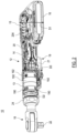
- power tool 10 which in this exemplary embodiment is an electric ratchet wrench for applying torque to a fastener, includes a housing 12 formed by two clam shells.
- the housing 12 is elongated along a longitudinal axis and includes a motor case 13 within which an electric brushless motor 100 is disposed, a handle portion 14 extending rearwardly from the motor case 13 within which a control and/or power module 20 are supported, and a battery receiving portion 15 disposed at a rear end of the handle portion 14.
- the control and/or power module 20 is thus disposed between the battery receiving portion 15 and the motor 100.
- the control and/or power module 20 includes control and switching components, for example an inverter switch circuit controlled by a programable controller, that controls flow of electric current to the motor 100.
- a trigger assembly 19 is mounted on the handle portion 14 of the housing 12 that electrically communicates with the control and/or switch module 20.
- the trigger assembly 19 includes a trigger switch 21 engageable by a user. Actuation of the trigger switch 21 sends a signal to the controller to begin operating the motor 100.
- the battery receiving portion 15 is configured to receive and lock in a sliding battery pack 16, such as a 20V Max power tool battery pack.
- the battery receiving portion 15 allows the battery pack 16 to be received along a sliding axis that is substantially parallel to the longitudinal axis of the housing 12. This ensures that the battery pack 16 is contained within approximately an envelope of the housing 12.
- the total width D1 of the battery receiving portion 15 plus the battery pack 16 is between approximately 25% to 40% greater than a width D2 of the motor case formed around the motor 100, and between approximately 15% to 25% greater than a width D3 formed by the trigger switch 21 and the handle portion 14.
- a ratchet head 18 is mounted on a front end of the housing 12 forward of the motor case 13.
- motor 100 is orientated along the longitudinal axis of the housing 12 to provide a rotary output to the ratchet head 18 to drive an output member 22.
- a nut 24 is mounted at the end of the housing 12 to secure the ratchet head 18 to the motor 100.
- Fig. 3 depicts a side perspective view of the motor 100, according to an embodiment.
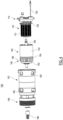
- Fig. 4 depicts a side exploded view of the motor 100, according to an embodiment.
- Fig. 5 depicts a side cross-sectional view of the motor 100, according to an embodiment.
- motor 100 is an outer-rotor brushless (BLDC) motor 100 contained in a motor can (or motor housing) 102.
- motor 100 includes an inner stator assembly 110 disposed within an outer rotor assembly 140, according to an embodiment.
- stator assembly 110 includes a stator lamination stack 112 formed by a series of steel laminations.
- the stator lamination stack 112 is mounted on a stator mount 114 and supports a series of stator windings 116.
- the stator windings 116 are wound in three phases, which, when respectively energized by the control and/or power module 20, cause rotation of the rotor assembly 140.
- a set of power wires 130 are received through the stator mount 114 and coupled to the stator windings 116.
- stator mount 114 includes an elongated cylindrical portion 122 sized to be received securely within a central aperture of the stator lamination stack 112.
- stator lamination stack 112 may be press-fitted over the cylindrical portion 122 of the stator mount 114.
- stator mount 114 further includes a radial body 120 at an end of the cylindrical portion 122 outside the body of the stator lamination stack 112. The radial body 120 forms a center bearing support pocket 124, which as described below, securely receives a rear bearing 162 of the rotor assembly 140.
- a positional sensor board 126 is mounted on an end of the stator lamination stack 112, between the stator lamination stack 112 and the stator mount 114.
- the positional sensor board 126 includes a series of Hall sensors positioned for sensing a rotary position of the rotor assembly 140.
- a set of signal wires 128 are secured to the positional sensor board 126 to carry signals from the Hall sensors to the control and/or power module 20.
- rotor assembly 140 includes a cylindrical rotor core 142 formed around the stator assembly 110, and a series of permanent magnets 144 surface-mounted on the inner surface of the rotor core 142 facing the stator assembly 110 with a small airgap therebetween. As the stator windings 116 are energized in a controlled pattern, they magnetically interact with permanent magnets 144, thus causing the rotation of the rotor.
- the rotor assembly 140 mounted securely on a rotor shaft 160 via a rotor mount 146. Rotation of the rotor assembly 140 causes rotation of the rotor shaft 160.
- a pinion 166 is mounted on a front end of the rotor shaft 160 for coupling the rotor shaft 160 to gear components (not shown) of the ratchet head 18.
- rotor mount 146 includes an inner body 148 that is substantially cylindrical and is mounted on the rotor shaft 160 via a bushing 150.
- the rotor mount 146 further includes a radial body 152 extending from the inner body 148 and an outer ring 154 that is securely coupled to the end of the rotor core 142 via a lip 158 shaped to be form-fittingly received through the end of the rotor core 143.
- a fan 156 is formed by a series of spaced-apart fan blades extending between the radial body 152 and the outer ring 154. As the rotor assembly 140 is rotated, the fan 156 generates an airflow through the stator assembly 110 and the rotor assembly 140.
- motor can 102 includes a generally cylindrical body having two open ends.
- the stator assembly 110 and rotor assembly 140 are received within the motor can 102, with an air gap maintained between the rotor core 142 and the inner surface of the motor can 102.
- stator mount 114 is secured to one end of the motor can 102 via a set of fasteners 118. Since the cylindrical portion 122 of the stator mount 114 supports the stator assembly 110, the stator mount 114 provides structural support for the stator assembly 110 relative to the motor can 102.
- the rotor mount 146 is received within the motor can 102 along with the rotor assembly 140.
- the motor can 102 includes a radial wall 103 that projects inwardly and forms a bearing support pocket 104 adjacent the rotor mount 146.
- the bearing support pocket 104 receives a front bearing 164 of the rotor shaft 160.
- the stator mount 114 and the motor can 102 cooperatively provides structural support for the rotor assembly 140 to be freely rotatably within the motor can 102.
- the rotor shaft 160 extends through the bearing support pocket 104.
- the pinion 166 which is coupled to the end of the rotor shaft 160, is provided within the front portion 108 of the motor can 102.
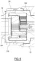
- Fig. 6 depicts a partial cross-sectional view of the front portion 108 of the motor can 102 coupled to the ratchet head 18.
- the ratchet head 18 includes an open rear end 170 that includes approximately the same outer diameter D4 as the front portion 108 of the motor can 102.
- the outer circumferences of both the open rear end 170 of the ratchet head 18 and the front portion 108 of the motor can 102 are threaded, providing a uniform outer surface that allows the nut 24 to be fastened and securely support the ratchet head 18 to the motor can 102.
- the nut 24 has an outer diameter that is smaller than or equal to the diameter of the motor case 13.
- Fig. 7 depicts a partial exploded view of the stator assembly 110 and the stator mount 114, according to an embodiment.
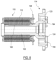
- Fig. 8 depicts a partial side cross-sectional view of the stator assembly 110 and the stator mount 114, according to an embodiment.
- Fig. 9 depicts an axial view of the stator assembly 110, according to an embodiment.
- the stator lamination stack 112 of the stator assembly 110 includes a stator core 180 mounted having an annular body sized to be fittingly mounted on the elongated cylindrical portion 122 of the stator mount 114.
- the lamination stack 112 further includes on a series of radially-outwardly projecting teeth on which the stator windings 116 are wound.
- the elongated cylindrical portion 122 of the stator mount 114 extends approximately through the entire length of the stator lamination stack 112.
- a tongue and groove structure is provided.
- the stator core 180 is provided with a tongue 182 that projects radially from its inner surface.
- the tongue 182 may be approximately 0.5 to 1 millimeter in lateral width, and in an embodiment, extends through approximately half to 3 ⁇ 4 of the length of stator lamination stack 112.
- tongue 182 may be formed by forming at least a subset of the steel laminations using a die that integrally incorporates the tongue 182 into the lamination stack 112.
- the elongated cylindrical portion 122 of the stator mount 114 is provided with a corresponding groove 184 sized to slidingly receive the tongue 182 therein as the stator assembly 110 is mounted.
- the cylindrical portion 122 of the stator mount 114 may be provided with a tongue and the stator lamination stack 112 of the stator assembly 110 may be provided with a corresponding groove. It should further be understood that instead of a tongue and groove structure, other alignment and/or poka-yoke structures may be utilized to radially align the stator mount 114 and the stator assembly 110.
- the motor can 102 is provided with a series of exhaust openings 190 formed radially around the fan 156.
- four exhaust openings 190 are provided around the fan 156.
- the motor case 13 portion of the housing 12 similarly includes a series of exhaust openings 200 radially aligned with the exhaust openings 190 of the motor can 102.
- the radial wall 103 of the motor can 102 and/or the stator assembly 110 cooperatively or individually form a baffle for the fan 156 to expel the airflow radially.
- the motor can 102 further includes a series of radial intake openings 192 provided near a rear end of the motor can 102 adjacent the stator mount 114.
- the radial intake openings 192 are provided along a radial plane between the positional sensor board 126 and the stator mount 114.
- four intake openings 192 are provided in alignment with the exhaust openings 190.
- the housing 12 similarly includes a series of radial intake openings 202 radially aligned with the intake openings 192 of the motor can 102.
- the radial intake openings 192 of the motor can 102 and the radial intake openings 202 of the housing 12 cooperate to allow entry of a first airstream of ambient air in the radial direction into the motor can 102, bypassing the handle portion 14 of the housing 12.
- the housing 12 includes a second set of intake openings 204 provided at or adjacent the battery receiving portion 15, which allow entry of a second airstream of ambient air through at least the handle portion 14 of the housing 12.
- the stator mount 114 includes a series of openings 194 formed in the radial body 120. The openings 194 allow entry of the second airstream from the handle portion 12 along approximately the axial direction into the motor can 102. Accordingly, the total airflow in the motor can 102 includes the first airstream received radially through the radial intake openings 192 and the second airstream received through the openings 194 of the radial body 120.
- the fan 156 is fully contained within the motor can 102 and includes an outer diameter that is approximately smaller than or equal to the outer diameter of the rotor core 142.
- the maximum diameter of the rotor core 142 is smaller than approximately 35 mm, preferably smaller than approximately 32 mm, preferably smaller than approximately 30.5 mm.
- motor case 13 of the tool housing 12 includes a small diameter, particularly in a front portion of the housing 12 where the ratchet head 18 is mounted.
- motor case 13 includes an outer diameter that is smaller than approximately 45 mm, at least in a lateral direction, and at least at the front portion of the housing 12.
- the fan 156 rotates at a top no-load speed of approximately greater than or equal to 22,000 rpm, preferably greater than 27,000 rpm.
- the ratchet head 18 provides significant gear reduction, which enables the fan 156 to rotate at a significantly higher speed than the output member 22.
- the rotational speed of the fan 156 combined with the arrangement of the air intake and exhaust openings described above, provide sufficient cooling airflow for the motor 100 and other power tool 10 components without a need for a secondary fan and despite the small diameter of the fan 156. This is a significant improvement over similar compact motor applications that typically require a fan having a larger diameter than the rotor core to efficiently cool the motor.
- At least one of the openings 194 of the radial body 120 extends to the outer periphery of the radial body 120 forming a cutout area 196.
- the cutout area 196 allows the power wires 130 and/or the signal wires 128 to be radially slid into the corresponding opening 194 after the stator assembly 110 is mounted on the stator mount 114. This eliminates the additional step of axially inserting the power wires 130 and/or the signal wires 128 into the opening 194 prior to mounting the stator assembly 110 on the stator mount 114.
- Example embodiments have been provided so that this disclosure will be thorough, and to fully convey the scope to those who are skilled in the art. Numerous specific details are set forth such as examples of specific components, devices, and methods, to provide a thorough understanding of embodiments of the present disclosure. It will be apparent to those skilled in the art that specific details need not be employed, that example embodiments may be embodied in many different forms and that neither should be construed to limit the scope of the disclosure. In some example embodiments, well-known processes, well-known device structures, and well-known technologies are not described in detail.
- first, second, third, etc. may be used herein to describe various elements, components, regions, layers and/or sections, these elements, components, regions, layers and/or sections should not be limited by these terms. These terms may be only used to distinguish one element, component, region, layer or section from another region, layer or section. Terms such as “first,” “second,” and other numerical terms when used herein do not imply a sequence or order unless clearly indicated by the context. Thus, a first element, component, region, layer or section discussed below could be termed a second element, component, region, layer or section without departing from the teachings of the example embodiments.
Landscapes
- Engineering & Computer Science (AREA)
- Power Engineering (AREA)
- Mechanical Engineering (AREA)
- Iron Core Of Rotating Electric Machines (AREA)
- Connection Of Motors, Electrical Generators, Mechanical Devices, And The Like (AREA)
Applications Claiming Priority (1)
| Application Number | Priority Date | Filing Date | Title |
|---|---|---|---|
| US17/455,688 US12176794B2 (en) | 2021-11-19 | 2021-11-19 | Outer-rotor brushless motor for a power tool |
Publications (1)
| Publication Number | Publication Date |
|---|---|
| EP4184762A2 true EP4184762A2 (de) | 2023-05-24 |
Family
ID=84332026
Family Applications (1)
| Application Number | Title | Priority Date | Filing Date |
|---|---|---|---|
| EP22202102.4A Pending EP4184762A2 (de) | 2021-11-19 | 2022-10-18 | Bürstenloser aussenläufermotor für ein elektrowerkzeug |
Country Status (2)
| Country | Link |
|---|---|
| US (2) | US12176794B2 (de) |
| EP (1) | EP4184762A2 (de) |
Cited By (1)
| Publication number | Priority date | Publication date | Assignee | Title |
|---|---|---|---|---|
| EP4568065A1 (de) * | 2023-12-08 | 2025-06-11 | Black & Decker, Inc. | Bürstenloser motor in einem elektrowerkzeug |
Citations (1)
| Publication number | Priority date | Publication date | Assignee | Title |
|---|---|---|---|---|
| US20190058373A1 (en) | 2014-12-18 | 2019-02-21 | Black & Decker Inc. | Brushless motor assembly for a fastening tool |
Family Cites Families (176)
| Publication number | Priority date | Publication date | Assignee | Title |
|---|---|---|---|---|
| GB1578268A (en) | 1976-06-01 | 1980-11-05 | Fujitsu Fanuc Ltd | Machine tool |
| CA1103298A (en) | 1977-02-25 | 1981-06-16 | Masami Uchiyama | Electric motor with discrete rotor position and speed sensors |
| US4540906A (en) | 1984-03-09 | 1985-09-10 | Synektron Corporation | Stator assembly for permanent magnet rotary device |
| DE3533898A1 (de) | 1985-09-23 | 1987-04-02 | Siemens Ag | Lagerflansch, insbesondere fuer einen einseitig und axial verspannt gelagerten aussenlaeufermotor |
| US5182848A (en) | 1987-07-24 | 1993-02-02 | Black & Decker Inc. | Method for assembling a stator subassembly |
| US4885496A (en) | 1987-07-24 | 1989-12-05 | Black & Decker Inc. | Stator end member and assemblies therewith and methods of assembly |
| US5099164A (en) | 1987-07-24 | 1992-03-24 | Black & Decker Inc. | Stator end member winding support shroud |
| US5241229A (en) | 1990-01-11 | 1993-08-31 | Sankyo Seiki Mfg. Co., Ltd. | Magnetic disc drive motor |
| US6069766A (en) | 1990-02-09 | 2000-05-30 | Seagate Technology, Inc. | Miniature hard disc drive having low profile actuator arm voice coil and spindle motors |
| US5144183A (en) | 1990-11-20 | 1992-09-01 | Kollmorgen Corporation | Flat motor of reduced length |
| US5245234A (en) | 1990-12-28 | 1993-09-14 | Nippon Densan Corporation | Motor |
| DE4136996B4 (de) | 1991-11-11 | 2011-03-10 | Papst Licensing Gmbh & Co. Kg | Plattenspeicherantrieb |
| US5497040A (en) | 1993-11-30 | 1996-03-05 | Sanyo Electric Co., Ltd. | Outer rotor type brusless DC motor |
| US6282053B1 (en) | 1994-08-05 | 2001-08-28 | Seagate Technology, Inc. | Adhesiveless disc drive spindle assembly |
| US5591017A (en) | 1994-10-03 | 1997-01-07 | Ametek, Inc. | Motorized impeller assembly |
| US5654598A (en) | 1995-12-14 | 1997-08-05 | Siemens Electric Limited | Brushless motor with inside mounted single bearing |
| US5844338A (en) | 1995-12-18 | 1998-12-01 | Siemens Electric Limited | Slim-line brushless motor with inside mounted single bearing |
| JPH09209973A (ja) | 1996-09-05 | 1997-08-12 | Hitachi Ltd | 水中モータ |
| JP3266559B2 (ja) | 1997-08-26 | 2002-03-18 | 三星電機株式会社 | ブラシレスdcモータ |
| JP3640815B2 (ja) | 1998-11-05 | 2005-04-20 | 株式会社東芝 | ファン装置及び冷蔵庫 |
| DE29901967U1 (de) | 1999-02-05 | 2000-07-13 | ebm Werke GmbH & Co., 74673 Mulfingen | Elektromotor mit einer Anordnung zur Drehzahlüberwachung |
| US20010013732A1 (en) | 1999-03-19 | 2001-08-16 | Chun-Pu Hsu | Anti-vibration electric motor having outer rotor stably supported at two ends |
| RO120023B1 (ro) | 1999-05-26 | 2005-07-29 | Iancu Lungu | Motor electric de curent continuu, cu comutaţie electronică |
| US6437464B1 (en) | 1999-07-29 | 2002-08-20 | Encap Motor Corporation | Motor and disc assembly for computer hard drive |
| US6501616B1 (en) | 1999-07-29 | 2002-12-31 | Encap Motor Corporation | Hard disc drive with base incorporating a spindle motor stator |
| US6362554B1 (en) | 1999-07-29 | 2002-03-26 | Encap Motor Corporation | Stator assembly |
| US6300695B1 (en) | 1999-07-29 | 2001-10-09 | Encap Motor Corporation | High speed spindle motor with hydrodynamic bearings |
| DE19940457A1 (de) | 1999-08-25 | 2001-03-01 | Wilo Gmbh | Axialflußmotor |
| DE10003153A1 (de) | 2000-01-26 | 2001-08-02 | Leybold Vakuum Gmbh | Turboradialgebläse |
| JP2001339902A (ja) | 2000-05-26 | 2001-12-07 | Hitachi Ltd | 外転型電動機 |
| GB2390488B (en) | 2002-02-04 | 2006-11-08 | Milwaukee Electric Tool Corp | Electrical devices including a switched reluctance motor |
| JP3999566B2 (ja) | 2002-05-22 | 2007-10-31 | マブチモーター株式会社 | ターンテーブル一体型のスピンドルモータ |
| EP1516418B1 (de) | 2002-06-26 | 2011-03-23 | Amotech Co., Ltd. | Bürstenloser Gleichstrommotor mit einem radialen Kern und einer Struktur mit einem Doppelrotor |
| US6617747B1 (en) | 2002-07-02 | 2003-09-09 | Petersen Technology Corporation | PM motor and generator with a vertical stator core assembly formed of pressure shaped processed ferromagnetic particles |
| JP2004040926A (ja) | 2002-07-04 | 2004-02-05 | Minebea Co Ltd | ファンモータ |
| TW547869U (en) | 2002-07-10 | 2003-08-11 | Hon Hai Prec Ind Co Ltd | Bearing device for motor |
| JP2004248332A (ja) | 2002-12-25 | 2004-09-02 | Tokyo Parts Ind Co Ltd | スピンドルモータ |
| EP1450467A1 (de) | 2003-02-21 | 2004-08-25 | Askoll Holding S.r.l. | Synchronmotor mit einer Riemenscheibe und Verfahren zur Herstellung des Synchronmotors |
| DE10320288A1 (de) | 2003-05-07 | 2004-12-02 | Gerhard Kocherscheidt | Elektromotor |
| DE20307048U1 (de) | 2003-05-07 | 2003-08-14 | Kocherscheidt Gerhard | Elektromotor |
| KR101096469B1 (ko) | 2003-07-10 | 2011-12-20 | 마그네틱 애플리케이션 인크. | 소형 고전력 교류 발전기 |
| ES2327503T3 (es) | 2003-09-03 | 2009-10-30 | Ziehl-Abegg Ag | Motor con rotor exterior. |
| US6798111B1 (en) | 2003-11-13 | 2004-09-28 | Petersen Technology Corporation | Plastic encapsulated electrodynamic apparatus |
| JP2005223977A (ja) | 2004-02-04 | 2005-08-18 | Matsushita Electric Ind Co Ltd | 電動ファン |
| KR20050089355A (ko) | 2004-03-04 | 2005-09-08 | 엘지전자 주식회사 | 대용량 드럼세탁기용 비엘디시 모터 |
| DE202004010513U1 (de) | 2004-07-06 | 2005-11-24 | Ebm-Papst Mulfingen Gmbh & Co. Kg | Elektromotor mit hohem Schutzgrad gegen das Eindringen von Fremdkörpern und Nässe |
| US7166948B2 (en) | 2004-09-15 | 2007-01-23 | Petersen Technology Corporation | Apparatus and method for dissipating a portion of the commutation derived collapsing field energy in a multi-phase unipolar electric motor |
| DE502005001019D1 (de) | 2004-11-23 | 2007-08-23 | Ebm Papst St Georgen Gmbh & Co | Anordnung zur förderung von fluiden |
| EP1696537A1 (de) | 2005-02-25 | 2006-08-30 | Askoll Holding S.r.l. | Struktur eines elektrischen Synchronmotors, insbesondere für Waschmaschinen mit einer rotierenden Trommel, die durch einen Riemenscheibenantrieb mit dem Motor kinematisch gekoppelt ist |
| DE102005011020A1 (de) | 2005-03-10 | 2006-09-14 | Georg-Friedrich Blocher | Getriebeloser und kompakter Hebezeugantrieb in Außenläuferausführung |
| US20070063595A1 (en) | 2005-03-23 | 2007-03-22 | Farhad Habibi | Electric machine and method of manufacture |
| TWI285017B (en) | 2005-06-30 | 2007-08-01 | Delta Electronics Inc | Brushless DC motor and magnetic compensation method thereof |
| DE102005049261B3 (de) | 2005-10-14 | 2007-03-29 | Siemens Ag | Kühlerlüfter für ein Kraftfahrzeug |
| US20070145838A1 (en) | 2005-12-07 | 2007-06-28 | Nidec Corporation | Motor and Method of Manufacturing Housing |
| EP1816727A3 (de) | 2006-02-03 | 2011-04-06 | ebm-papst St. Georgen GmbH & Co. KG | Elektromotor |
| EP1816729B1 (de) | 2006-02-03 | 2015-10-21 | ebm-papst St. Georgen GmbH & Co. KG | Elektromotor |
| US8049382B2 (en) | 2006-05-08 | 2011-11-01 | Panasonic Corporation | Brushless motor |
| JP4857924B2 (ja) | 2006-06-09 | 2012-01-18 | マックス株式会社 | ブラシレスモータ |
| KR20080026874A (ko) | 2006-09-21 | 2008-03-26 | 엘지전자 주식회사 | 외전형 팬모터 및 외전형 팬모터용 자석의 착자방법 |
| JP4291846B2 (ja) | 2006-11-24 | 2009-07-08 | アスモ株式会社 | ファンモータ |
| JP2008138526A (ja) | 2006-11-30 | 2008-06-19 | Daikin Ind Ltd | 圧縮機 |
| JP2008211914A (ja) | 2007-02-26 | 2008-09-11 | Ricoh Co Ltd | 回転駆動装置、光走査装置及び画像形成装置 |
| JP5081005B2 (ja) | 2007-03-09 | 2012-11-21 | アスモ株式会社 | ブラシレスモータ及びその製造方法 |
| JP5057845B2 (ja) | 2007-05-14 | 2012-10-24 | 津田駒工業株式会社 | 工作機械用の角度割出し装置 |
| EP1995853A1 (de) | 2007-05-24 | 2008-11-26 | Alcatel Lucent | Elektromotor |
| JP2008312356A (ja) | 2007-06-14 | 2008-12-25 | Nippon Densan Corp | 回路基板およびこの回路基板を用いたブラシレスモータ |
| JP2009100573A (ja) | 2007-10-17 | 2009-05-07 | Asmo Co Ltd | ブラシレスモータ |
| JP5064992B2 (ja) | 2007-12-13 | 2012-10-31 | アスモ株式会社 | ブラシレスモータ及びその製造方法 |
| US7687959B1 (en) | 2007-12-17 | 2010-03-30 | Lee S Peter | Brushless a-c motor |
| CN101543967B (zh) | 2008-03-28 | 2011-12-28 | 德昌电机(深圳)有限公司 | 带冷却系统的电钻 |
| GB0809868D0 (en) | 2008-05-30 | 2008-07-09 | Black & Decker Inc | Fastener driving tool |
| US20090295243A1 (en) | 2008-06-03 | 2009-12-03 | Lawrence Leroy Kneisel | Method for mounting an inner stator for a motor |
| US8133143B2 (en) | 2008-06-16 | 2012-03-13 | Fairfield Manufacturing Company, Inc. | Gear reducer electric motor assembly with internal brake |
| DE102008047494A1 (de) | 2008-09-17 | 2010-04-15 | Continental Teves Ag & Co. Ohg | Elektronisch kommutierter Gleichstrommotor |
| JP2010093905A (ja) | 2008-10-06 | 2010-04-22 | Sanyo Denki Co Ltd | ブラシレスモータ用ステータ |
| WO2010087235A1 (en) * | 2009-01-30 | 2010-08-05 | Hitachi Koki Co., Ltd. | Power tool |
| JP5472683B2 (ja) | 2009-05-11 | 2014-04-16 | 日立工機株式会社 | 電動工具 |
| JP5478117B2 (ja) | 2009-05-21 | 2014-04-23 | アスモ株式会社 | モータ |
| KR20120055546A (ko) | 2009-07-02 | 2012-05-31 | 아스콜 홀딩 에스.알.엘. | 개선된 동기 전동기 |
| CN101941200B (zh) | 2009-07-03 | 2015-03-25 | 德昌电机(深圳)有限公司 | 电动工具及其马达组件 |
| FR2948510B1 (fr) | 2009-07-24 | 2011-08-26 | Ssd Parvex Sas | Moteur mono palier |
| WO2011113522A2 (de) | 2010-03-15 | 2011-09-22 | Ebm-Papst St. Georgen Gmbh & Co. Kg | Aussenläufermotor |
| US8584770B2 (en) | 2010-03-23 | 2013-11-19 | Black & Decker Inc. | Spindle bearing arrangement for a power tool |
| DE102010013756A1 (de) | 2010-03-31 | 2011-10-06 | Andreas Stihl Ag & Co. Kg | Handgeführtes Arbeitsgerät |
| US8410643B2 (en) | 2010-07-22 | 2013-04-02 | Globe Motors, Inc. | Frameless electric motor assembly |
| DE102012102042A1 (de) | 2011-03-12 | 2012-09-13 | Karl-Ludwig Blocher | Rotierende elektrische Maschine in Außenläuferausführung als Transversalfluss-Klauenpolmaschine |
| US8449424B2 (en) | 2011-03-17 | 2013-05-28 | Fairfield Manufacturing Company Inc. | Integral electric motor with speed sensor, planetary gearbox and steering means |
| JP5705648B2 (ja) | 2011-05-23 | 2015-04-22 | 株式会社マキタ | 電動工具 |
| JP5826526B2 (ja) * | 2011-06-08 | 2015-12-02 | 株式会社マキタ | 電動工具 |
| JP6084612B2 (ja) * | 2011-08-11 | 2017-02-22 | モル ベルティング システムズ, インコーポレイテッドMol Belting Systems, Inc. | サイクロ減速機装置 |
| JP2013144340A (ja) | 2012-01-16 | 2013-07-25 | Makita Corp | 電動工具 |
| JP2013151055A (ja) | 2012-01-26 | 2013-08-08 | Makita Corp | 打撃工具 |
| JP5935983B2 (ja) | 2012-03-29 | 2016-06-15 | 日立工機株式会社 | 電動工具 |
| US8963392B2 (en) | 2012-04-13 | 2015-02-24 | Regal Beloit America, Inc. | Axial load sharing bearing system and associated method of use |
| CN103373383B (zh) | 2012-04-17 | 2018-06-19 | 德昌电机(深圳)有限公司 | 电动推车及其齿轮电机组件 |
| ITTV20120063A1 (it) | 2012-04-17 | 2013-10-18 | Fcs System S R L | Elettromandrino per macchine a controllo numerico |
| FR2991210B3 (fr) | 2012-05-29 | 2014-09-05 | Chang Peng Invest Co Ltd | Machine-outil de petite dimension |
| JP5955155B2 (ja) | 2012-08-09 | 2016-07-20 | アスモ株式会社 | ブラシレスモータ |
| JP6049965B2 (ja) | 2012-10-09 | 2016-12-21 | 東京パーツ工業株式会社 | ブラシレスモータ |
| EP2908984B1 (de) | 2012-10-19 | 2018-01-24 | Husqvarna AB | Internes kühlsystem für elektrowerkzeug zur verwendung im freien |
| DE102012221758A1 (de) | 2012-11-28 | 2014-05-28 | Robert Bosch Gmbh | Handwerkzeugmaschine |
| DE102012221748A1 (de) | 2012-11-28 | 2014-05-28 | Robert Bosch Gmbh | Handwerkzeugmaschine |
| KR101309689B1 (ko) | 2012-11-29 | 2013-10-14 | 주식회사 한일파테크 | 전기기기용 비엘디씨(bldc) 모터 |
| AU2013364501B2 (en) | 2012-12-21 | 2017-09-14 | Fisher & Paykel Appliances Limited | A motor |
| FR3001449B1 (fr) | 2013-01-25 | 2019-08-16 | Moteurs Leroy-Somer | Machine d'entrainement d'un ascenseur. |
| US10000900B2 (en) | 2013-02-20 | 2018-06-19 | Chervon (Hk) Limited | Handheld blower having engine cooling flow |
| JP6011801B2 (ja) | 2013-02-27 | 2016-10-19 | 日立工機株式会社 | 電動工具 |
| DE102013204436A1 (de) | 2013-03-14 | 2014-09-18 | Krones Ag | Antrieb für eine Transportvorrichtung, Satz von Antrieben und Verfahren zum Antreiben einer Transportvorrichtung |
| CN203387367U (zh) | 2013-07-18 | 2014-01-08 | 日本电产株式会社 | 外转子型马达 |
| US9762153B2 (en) | 2013-10-18 | 2017-09-12 | Black & Decker Inc. | Cycle-by-cycle current limit for power tools having a brushless motor |
| US9314900B2 (en) | 2013-10-18 | 2016-04-19 | Black & Decker Inc. | Handheld grinder with a brushless electric motor |
| US9325224B2 (en) | 2013-12-28 | 2016-04-26 | Google Inc. | Electrically-isolated and liquid-cooled rotor and stator assemblies |
| JP5700266B2 (ja) | 2014-01-10 | 2015-04-15 | 日立工機株式会社 | 電動工具 |
| CN103956846B (zh) | 2014-04-04 | 2017-05-17 | 苏州泰格动力机器有限公司 | 一种浅水用多极永磁电机和使用它的浅水式潜水泵 |
| KR101611492B1 (ko) | 2014-04-21 | 2016-04-12 | 주식회사 효성 | 모터의 회전자 |
| CN105099041A (zh) | 2014-04-22 | 2015-11-25 | 德昌电机(深圳)有限公司 | 无刷电机、无刷电机的外转子及其制造方法 |
| US10651702B2 (en) | 2014-09-04 | 2020-05-12 | Coreless Motor Co., Ltd. | Coreless rotating electrical machine with stator including cylindrical coil and cooling method therefor |
| DE102014220493A1 (de) | 2014-10-09 | 2016-04-14 | Zf Friedrichshafen Ag | Antriebseinheit für ein Hybridmodul |
| US9929627B2 (en) | 2014-11-03 | 2018-03-27 | Goodrich Corporation | Brushless motor with modular position sensor |
| JP6408870B2 (ja) | 2014-11-05 | 2018-10-17 | 株式会社マキタ | 電動工具 |
| JP6441648B2 (ja) | 2014-11-14 | 2018-12-19 | 株式会社マキタ | 電動作業機 |
| KR101674080B1 (ko) | 2014-12-04 | 2016-11-08 | 뉴모텍(주) | 버스바 어셈블리를 갖는 모터 |
| JP6429115B2 (ja) | 2014-12-25 | 2018-11-28 | 日本電産株式会社 | モータ |
| WO2016115921A1 (zh) | 2015-01-21 | 2016-07-28 | 中山大洋电机股份有限公司 | 一种外转子塑封电机及其应用的空调机 |
| US10011035B2 (en) | 2015-02-23 | 2018-07-03 | Makita Corporation | Machining device and electric motor for the same |
| CN204615524U (zh) | 2015-04-28 | 2015-09-02 | 中山大洋电机制造有限公司 | 一种外转子电机的塑封定子及其应用的外转子电机 |
| TW201642552A (zh) | 2015-05-28 | 2016-12-01 | 范揚鋒 | 馬達定子結構及其定子單元與製造方法 |
| FR3036889B1 (fr) | 2015-05-29 | 2019-05-17 | Valeo Systemes Thermiques | Moteur electrique a commutation electronique et dispositif de pulsion d'air correspondant |
| JP2017002749A (ja) | 2015-06-05 | 2017-01-05 | アイシン精機株式会社 | 電動ポンプ |
| CN204858804U (zh) | 2015-07-04 | 2015-12-09 | 中山大洋电机股份有限公司 | 一种用于安装定子组件的套筒座及其应用的外转子电机 |
| CN204835757U (zh) | 2015-07-04 | 2015-12-02 | 中山大洋电机股份有限公司 | 一种外转子电机及应用其的风机 |
| CA2992787C (en) | 2015-07-22 | 2024-01-30 | Cepheid | Encoderless motor with improved granularity and methods of use |
| JP6490528B2 (ja) | 2015-07-23 | 2019-03-27 | 東洋電装株式会社 | モータ、その回転周期検出方法、モータ回転周期検出センサアッセンブリ及び発電機 |
| DE102015114727A1 (de) | 2015-09-03 | 2017-03-09 | Alfing Kessler Sondermaschinen Gmbh | Werkzeugmaschine mit einer Feinbearbeitungsspindel |
| CN205265385U (zh) | 2015-12-23 | 2016-05-25 | 中山大洋电机股份有限公司 | 一种外转子电机的塑封定子及其应用的外转子电机 |
| CN106926097B (zh) | 2015-12-31 | 2020-01-31 | 南京德朔实业有限公司 | 角磨机 |
| CN108496300B (zh) | 2016-02-22 | 2022-05-27 | 深圳市大疆灵眸科技有限公司 | 电机位置感测 |
| ITUB20160930A1 (it) | 2016-02-22 | 2017-08-22 | Sit Spa | Struttura di motore elettrico in particolare per ventilatori per aria di combustione, o per miscela aria/gas di combustione, in bruciatori a gas, gruppo statorico per tale struttura di motore elettrico e procedimento di assemblaggio per tale gruppo statorico |
| CN107124064A (zh) | 2016-02-25 | 2017-09-01 | 德昌电机(深圳)有限公司 | 风机及其外转子电机 |
| KR101795219B1 (ko) | 2016-03-11 | 2017-11-07 | 현대자동차주식회사 | 비엘디씨 모터 조립체 |
| JP2017184533A (ja) | 2016-03-31 | 2017-10-05 | ミネベアミツミ株式会社 | スピンドルモータ |
| JP6648619B2 (ja) | 2016-04-19 | 2020-02-14 | 株式会社デンソー | ブラシレスモータ |
| CN107370270B (zh) | 2016-05-11 | 2020-08-18 | 德昌电机(深圳)有限公司 | 马达及马达的旋转组件 |
| CN107394956A (zh) | 2016-05-16 | 2017-11-24 | 德昌电机(深圳)有限公司 | 驱动装置及应用该驱动装置的车窗升降器 |
| JP6713208B2 (ja) | 2016-05-17 | 2020-06-24 | 株式会社ハーモニック・ドライブ・システムズ | モータ内蔵型波動歯車装置 |
| CN106026490B (zh) | 2016-05-17 | 2018-04-06 | 中山大洋电机股份有限公司 | 用轴向间隔减震圈安装的外转子电机及应用其的风机负载 |
| CN107516958B (zh) | 2016-06-15 | 2020-12-01 | 德昌电机(深圳)有限公司 | 转子、具有该转子的电机及电动工具 |
| CN205901554U (zh) | 2016-07-26 | 2017-01-18 | 中山大洋电机股份有限公司 | 一种外转子电机 |
| CN109565197A (zh) | 2016-08-05 | 2019-04-02 | 日本电产株式会社 | 马达 |
| CN109565208B (zh) | 2016-08-05 | 2021-06-08 | 日本电产株式会社 | 马达 |
| US10637312B2 (en) | 2016-09-16 | 2020-04-28 | Amazon Technologies, Inc. | Motor magnet placement to alter generated sound |
| FR3056846B1 (fr) | 2016-09-26 | 2022-08-12 | Valeo Systemes Dessuyage | Moteur electrique a courant continu sans balais pour systeme d'essuyage de vehicule automobile |
| FR3056844B1 (fr) | 2016-09-26 | 2022-08-12 | Valeo Systemes Dessuyage | Moteur electrique a courant continu sans balais pour systeme d'essuyage de vehicule automobile |
| FR3056845B1 (fr) | 2016-09-26 | 2021-07-30 | Valeo Systemes Dessuyage | Moteur electrique a courant continu sans balais pour systeme d'essuyage de vehicule automobile |
| TWI591938B (zh) | 2016-09-29 | 2017-07-11 | 建準電機工業股份有限公司 | 外轉子馬達及其定子組件 |
| JP2018074685A (ja) | 2016-10-26 | 2018-05-10 | マブチモーター株式会社 | ブラシレスモータ |
| CN108075583B (zh) | 2016-11-17 | 2022-10-04 | 德昌电机(深圳)有限公司 | 一种外转子电机及应用该电机的滚刷吸尘器 |
| JP6762611B2 (ja) | 2016-12-14 | 2020-09-30 | 東京パーツ工業株式会社 | 軸受装置及びブラシレスモータ |
| CN108336838A (zh) | 2017-01-20 | 2018-07-27 | 德昌电机(深圳)有限公司 | 电机 |
| JP2018129999A (ja) | 2017-02-10 | 2018-08-16 | 日本電産株式会社 | モータ、及び電気機器 |
| AU2017405739A1 (en) | 2017-03-21 | 2019-10-17 | Tti (Macao Commercial Offshore) Limited | Brushless motor |
| JP2020112032A (ja) | 2017-05-08 | 2020-07-27 | パナソニックIpマネジメント株式会社 | 密閉型圧縮機およびそれを用いた冷凍装置 |
| CN107083644B (zh) | 2017-06-14 | 2019-10-22 | 常州新亚电机有限公司 | 一种洗衣机驱动系统以及洗衣机 |
| US10870562B2 (en) | 2017-07-11 | 2020-12-22 | Goodrich Corporation | System and method for hoist with integrated drum and motor |
| CA3014953A1 (en) | 2017-08-24 | 2019-02-24 | Valent U.S.A. Llc | Bispyribac mixtures |
| JP6616362B2 (ja) | 2017-09-04 | 2019-12-04 | シナノケンシ株式会社 | ブラシレスモータ及び固定子の巻線方法 |
| CN107834750B (zh) | 2017-11-24 | 2024-04-19 | 惠州市精电动力科技有限公司 | 一种外转子无刷电机 |
| KR102583066B1 (ko) | 2018-04-10 | 2023-09-27 | 엘지이노텍 주식회사 | 모터 |
| DE102018118628A1 (de) | 2018-08-01 | 2020-02-06 | Johnson Electric International AG | Aktuator |
| WO2020123245A1 (en) | 2018-12-10 | 2020-06-18 | Milwaukee Electric Tool Corporation | High torque impact tool |
| WO2020132587A1 (en) | 2018-12-21 | 2020-06-25 | Milwaukee Electric Tool Corporation | High torque impact tool |
| US11056936B2 (en) | 2019-04-15 | 2021-07-06 | Ford Global Technologies, Llc | Electric motor and construction methods thereof |
| EP3731376A1 (de) | 2019-04-24 | 2020-10-28 | Black & Decker Inc. | Statorträger eines bürstenlosen aussenläufermotors |
| CN110535284B (zh) | 2019-10-08 | 2024-04-05 | 河南澈蓝环保技术有限公司 | 一种高精度自平衡静音马达 |
| US11757330B2 (en) | 2019-12-19 | 2023-09-12 | Black & Decker, Inc. | Canned outer-rotor brushless motor for a power tool |
| DE102021201313A1 (de) | 2020-02-19 | 2021-08-19 | Robert Bosch Gesellschaft mit beschränkter Haftung | Statoranordnung und Verfahren zum Befestigen eines Blechpakets |
-
2021
- 2021-11-19 US US17/455,688 patent/US12176794B2/en active Active
-
2022
- 2022-10-18 EP EP22202102.4A patent/EP4184762A2/de active Pending
-
2024
- 2024-11-13 US US18/946,515 patent/US20250070620A1/en active Pending
Patent Citations (1)
| Publication number | Priority date | Publication date | Assignee | Title |
|---|---|---|---|---|
| US20190058373A1 (en) | 2014-12-18 | 2019-02-21 | Black & Decker Inc. | Brushless motor assembly for a fastening tool |
Cited By (1)
| Publication number | Priority date | Publication date | Assignee | Title |
|---|---|---|---|---|
| EP4568065A1 (de) * | 2023-12-08 | 2025-06-11 | Black & Decker, Inc. | Bürstenloser motor in einem elektrowerkzeug |
Also Published As
| Publication number | Publication date |
|---|---|
| US12176794B2 (en) | 2024-12-24 |
| US20250070620A1 (en) | 2025-02-27 |
| US20230163664A1 (en) | 2023-05-25 |
Similar Documents
| Publication | Publication Date | Title |
|---|---|---|
| US12095343B2 (en) | Electric motor for a power tool | |
| US20260074586A1 (en) | Brushless motor having an overmolded rotor | |
| US11670977B2 (en) | Outer rotor brushless motor stator mount | |
| EP2139095B1 (de) | Elektrisches Werkzeug mit elektrischem Hybridmotordesign | |
| US11646639B2 (en) | Electric power tool | |
| US12218567B2 (en) | Power tool having an outer-rotor brushless motor | |
| US12463502B2 (en) | Outer-rotor motor assembly | |
| US10044245B2 (en) | Electric motor with improved cooling | |
| EP1942571A1 (de) | Motor mit zwei rotoren und vorrichtung damit | |
| US20250070620A1 (en) | Power tool including a canned electric motor | |
| US20240364159A1 (en) | Overmolded rotor structure | |
| EP3840179B1 (de) | Modularer bürstenloser aussenläufermotor für ein elektrowerkzeug | |
| US11916447B2 (en) | Overmolded rotor structure | |
| US20220354052A1 (en) | Outer rotor brushless motor and planetary gear assembly for power tool | |
| JP2020141442A (ja) | ブラシレスモータおよび電動送風機 | |
| EP4404445A2 (de) | Kompakter bürstenloser aussenläufermotor für ein elektrowerkzeug | |
| US20250293556A1 (en) | Stator to rotor retention clip | |
| EP4568065A1 (de) | Bürstenloser motor in einem elektrowerkzeug | |
| EP4550640A1 (de) | Elektrowerkzeug mit einem aussenläufermotor |
Legal Events
| Date | Code | Title | Description |
|---|---|---|---|
| PUAI | Public reference made under article 153(3) epc to a published international application that has entered the european phase |
Free format text: ORIGINAL CODE: 0009012 |
|
| STAA | Information on the status of an ep patent application or granted ep patent |
Free format text: STATUS: THE APPLICATION HAS BEEN PUBLISHED |
|
| AK | Designated contracting states |
Kind code of ref document: A2 Designated state(s): AL AT BE BG CH CY CZ DE DK EE ES FI FR GB GR HR HU IE IS IT LI LT LU LV MC ME MK MT NL NO PL PT RO RS SE SI SK SM TR |