EP4077792B1 - Stichbildungswerkzeug-baugruppe für eine nähanlage sowie nähanlage mit einer derartigen baugruppe - Google Patents
Stichbildungswerkzeug-baugruppe für eine nähanlage sowie nähanlage mit einer derartigen baugruppe Download PDFInfo
- Publication number
- EP4077792B1 EP4077792B1 EP20820873.6A EP20820873A EP4077792B1 EP 4077792 B1 EP4077792 B1 EP 4077792B1 EP 20820873 A EP20820873 A EP 20820873A EP 4077792 B1 EP4077792 B1 EP 4077792B1
- Authority
- EP
- European Patent Office
- Prior art keywords
- needle
- sewing
- stitch
- forming tool
- tool assembly
- Prior art date
- Legal status (The legal status is an assumption and is not a legal conclusion. Google has not performed a legal analysis and makes no representation as to the accuracy of the status listed.)
- Active
Links
Images

Classifications
-
- D—TEXTILES; PAPER
- D05—SEWING; EMBROIDERING; TUFTING
- D05B—SEWING
- D05B57/00—Loop takers, e.g. loopers
- D05B57/02—Loop takers, e.g. loopers for chain-stitch sewing machines, e.g. oscillating
-
- D—TEXTILES; PAPER
- D05—SEWING; EMBROIDERING; TUFTING
- D05B—SEWING
- D05B57/00—Loop takers, e.g. loopers
- D05B57/30—Driving-gear for loop takers
- D05B57/32—Driving-gear for loop takers in chain-stitch sewing machines
Definitions
- the invention relates to a stitch forming tool assembly for a sewing machine for producing a double chain stitch seam.
- the invention further relates to a sewing machine with such an assembly.
- a double chain stitch sewing machine is known from the DD-PS 1111 02
- An adjustment device for a sewing machine hook is known from the DE 29 01 582 C2 .
- the DE-PS 104 963 discloses a device for extending thread loops in double chain stitch machines.
- the DE 39 35 779 C1 discloses a hook release device on a sewing machine.
- the US 6,095,069 reveals a double chain stitch sewing machine.
- the DE-PS 667 052 reveals a sewing needle with a thread cutting edge.
- the WO 2007/030809 A2 / EP 1 943 382 A0 discloses a multi-needle quilting machine and an operating method thereof.
- DD-PS 1111 02 and the DE 29 01 582 C2 show gripper drives from the state of the art that specify such an elliptical evasive movement path and are designed accordingly complexly.
- a correspondingly complex drive can be dispensed with in the assembly according to the invention.
- the sewing direction in the assembly according to the invention is in the swinging movement plane of the gripper, which is also referred to as an inline system.
- the gripper does not perform an evasive movement perpendicular to the swinging movement plane.
- the stitch forming tool assembly can be designed in such a way that it does not require a spreader finger to spread a thread loop and to facilitate threading into the thread loop.
- a spreader finger of this type, which can be dispensed with here, is known from obvious prior use from a chain stitch sewing machine of the Pfaff 5626 type.
- a central longitudinal axis of the sewing needle is spaced from a needle tip of the sewing needle. Such a spacing of the central longitudinal axis of the sewing needle from the needle tip enables an orientation of the sewing needle to the looper, which simplifies an obstruction-free relative movement of these stitch formation components during the stitch formation sequence.
- the needle in the assembly according to the invention can also be designed in such a way that it moves up and down exclusively in exactly one direction, i.e. in the needle piercing direction, and thus does not perform any evasive movement relative to the gripper.
- a sewing system according to claim 5 has the advantages that have already been explained above with reference to the stitch-forming tool assembly.
- the sewing system can include a sewing machine or a sewing machine, of which the stitch-forming tool assembly forms a component.
- Part of the sewing system can also be a robot that can move a sewing head with the stitch-forming tool assembly in a controlled/regulated manner in several degrees of freedom, so that even more complex sewing material geometries can be provided with defined seams, in particular with seams that run three-dimensionally in space.
- the sewing system can therefore be a sewing robot, the sewing head of which can be moved by several degrees of freedom of translation or rotation, or a sewing machine.
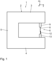
- Fig. 1 shows very schematically the main components of a sewing system 1, designed as a sewing robot.
- the sewing system 1 has a C-shaped frame 2 with an arm 3, a base plate 4 and a stand 5 which connects the arm 3 to the base plate 4.
- a component of the sewing system 1 can be a drive (not shown in detail) via which the frame 2 can be displaced in several degrees of freedom of translation or rotation, for example in three, four, five or six degrees of freedom.
- a drive of this type is known in connection with industrial robots. Accordingly, the sewing system 1 can be designed as a sewing robot.
- Shown in the Fig. 1 also a Cartesian xyz coordinate system to facilitate the arrangement of positional relationships.
- the x-axis runs to the Fig. 1 perpendicular to the plane of the drawing.
- the y-axis runs in the Fig. 1 to the right parallel to the extension of the arm 3 and the base plate 4.
- the z-axis runs in the Fig. 1 upwards parallel to the extension of the column 5.
- the axis directions x, y, z also apply to the following figures.
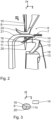
- Part of the sewing unit 1 is a stitch forming tool assembly 6 for producing a double chain stitch seam 7, for which Fig. 2 as well as in the Fig. 4 and 5 one pattern is shown in each case.
- a sewing direction runs along the x-direction, i.e. perpendicular to the yz-plane defined by the C-shape of frame 2.
- the assembly 6 has a sewing needle 8, which is held by a needle bar 9.
- the needle bar 9 and with it the sewing needle 8 can be moved up and down in a needle stitch direction along the z-axis perpendicular to a sewing material not shown in the drawing.
- the sewing needle 8 is designed to guide a needle thread 10, which is also referred to as the upper thread.
- the sewing needle 8 has an eye 11.
- the stitch formation assembly 6 also includes a hook 12, which in the side view is arranged according to the Fig. 2 , 4 and 5 is hook-shaped and is carried by a driven gripper carrier 13.
- the gripper 12 has a bent design.
- a threading section 14 of the gripper 12 has a thread passage opening 16, 17 for a gripper thread 18, which is also referred to as the lower thread, in the area of a gripper tip 15 and at its opposite end.
- the gripper 12 is designed to guide the gripper thread 18. Due to a drive of the gripper carrier 13 (not shown in detail), the gripper is also designed for oscillating movement in an oscillating movement plane that coincides with the xz plane, i.e. is spanned on the one hand by the needle stitch direction z and on the other hand by the sewing direction x along the double chain stitch seam 7.
- a movement path of the gripper lies during the entire double chain stitch, of which snapshots are taken in the Fig. 2 , 4 and 5 shown, completely in the swing motion plane xz.
- the gripper 12 therefore does not perform any evasive movement perpendicular to this oscillation plane xz.
- the sewing direction x is accordingly in the oscillating movement plane xz of the gripper 12.
- the sewing system 1 thus represents an inline system.
- the stitch forming tool assembly 6 does not include a spreader finger.
- a spreader finger of this type, which is not present here, is known, for example, from obvious prior use on a chain stitch sewing machine of the type Pfaff 5626.
- Fig. 3 shows a schematic plan view of the sewing needle 8 and of a broken section of the threading section 14 of the gripper 12.
- the illustration according to Fig. 3 enlarged.
- a view of the Fig. 3 runs along a central longitudinal axis 19 of the sewing needle 8.
- Shown in the Fig. 3 also a piercing point of a needle tip 20, through the drawing plane of the Fig. 3 . From this illustration it can be seen that the central longitudinal axis 19 of the sewing needle 8 is spaced apart from the needle tip 20 by a distance ⁇ y.
- the sewing needle 8 is therefore not rotationally symmetrical in the area of the needle tip 20, but the needle tip 20 is displaced by the distance ⁇ y in relation to an axis of symmetry of a needle base body, which coincides with the central longitudinal axis 19.
- the needle tip 20 is spaced perpendicularly to the oscillation plane xz by the distance ⁇ y from the central longitudinal axis 19.
- the central longitudinal axis 19 is located, as also shown in the Fig. 3 shown, between the needle tip 20 and the threading section 14 of the looper 12, i.e. between the needle tip 20 and the looper 12.
- This decentering of the needle tip 20 facilitates the guiding of the sewing needle 8 past the threading section 14, especially when Fig. 2 shown insertion of the needle tip 20 into a loop of the looper thread 18.
- the threading section 14 is guided past a tip section of the sewing needle 8 at a very short distance.
- the two components 8, 12 can also touch each other.
- a support element 21 for the sewing material and a presser or transport foot 22 for the sewing material are shown. During real sewing operation, the sewing material is moved between the support element 21 and the foot 22 in the sewing direction x.
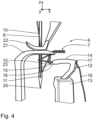
- Fig. 4 shows the moment of the formation sequence of the double chain stitch, at which the sewing needle 8 has arrived in the area of a lower dead center.
- the hook tip 15 is at the moment after Fig. 4 in the area of a Fig. 4 right dead center and deflected so far that in the projection after the Fig. 4 beyond a section 23 of the needle thread 10 leading out of the eye 11.
- Fig. 5 shows the moment of the stitch formation sequence at which the threading section 14 is threaded into a needle thread loop formed in the needle thread section 23 in the meantime due to the reversal of the movement of the sewing needle 8, whereby the looper thread 18 in the area of the thread passage opening 16 of the threading section 14 is also threaded through this loop of the Needle thread section 23 is passed through. The next time you insert the needle (see Fig.
- the sewing needle is again inserted into a loop of the looper thread 18 in the negative x-direction beyond this needle thread loop and after the threading section 14 of the looper 12 is retracted, the previously formed loop of the needle thread section 23, entwined with the looper thread 18, is thrown off the threading section 14, as can be seen from the Fig. 4 is visible.
- the well-known double chain stitch formation mechanism results.
- the seam 7 thus formed runs in the positive x-direction.
- Assembly group 6 can also be prepared as a conversion kit for a sewing machine.
Landscapes
- Engineering & Computer Science (AREA)
- Textile Engineering (AREA)
- Sewing Machines And Sewing (AREA)
Description
- Die vorliegende Patentanmeldung nimmt die Priorität der deutschen Patentanmeldung
DE 10 2019 219 814.7 in Anspruch, deren Inhalt durch Bezugnahme hierin aufgenommen wird. - Die Erfindung betrifft eine Stichbildungswerkzeug-Baugruppe für eine Nähanlage zur Erzeugung einer Doppelkettenstich-Naht. Ferner betrifft die Erfindung eine Nähanlage mit einer derartigen Baugruppe.
- Eine Doppelkettenstich-Nähmaschine ist bekannt aus der
DD-PS 1111 02 DE 29 01 582 C2 . DieDE-PS 104 963 offenbart eine Einrichtung zum Erweitern von Fadenschlingen bei Doppelkettenstich-Maschinen. DieDE 39 35 779 C1 offenbart eine Greiferausrückvorrichtung an einer Nähmaschine. DieUS 6,095,069 offenbart eine Doppelkettenstich-Nähmaschine. DieDE-PS 667 052 offenbart eine Nähnadel mit einer Fadenschneidkante. - Die
WO 2007/030809 A2 /EP 1 943 382 A0 offenbart eine Mehrnadel-Steppmaschine und ein Betriebsverfahren hierfür. - Es ist eine Aufgabe der vorliegenden Erfindung, eine Stichbildungswerkzeug-Baugruppe der eingangs genannten Art derart weiter zu bilden, dass insbesondere ein Greiferantrieb vereinfacht ist.
- Diese Aufgabe ist erfindungsgemäß gelöst durch eine Stichbildungswerkzeug-Baugruppe mit den im Anspruch 1 angegebenen Merkmalen.
- Erfindungsgemäß wurde erkannt, dass es nicht zwingend erforderlich ist, bei einer Doppelkettenstich-Nähanlage eine Greifer-Bewegungsbahn vorzusehen, bei der der Greifer relativ zur Nähnadel eine Ausweichbewegung senkrecht zu einer Schwing-Bewegungsebene des Greifers vollführt. Die
DD-PS 1111 02 DE 29 01 582 C2 zeigen Greiferantriebe aus dem Stand der Technik, die eine derartige elliptische Ausweich-Bewegungsbahn vorgeben und entsprechend komplex gestaltet sind. Auf einen entsprechend komplexen Antrieb kann bei der erfindungsgemäßen Baugruppe verzichtet werden. - Die Nährichtung liegt bei der erfindungsgemäßen Baugruppe in der Schwing-Bewegungsebene des Greifers, was auch als Inline-System bezeichnet ist. Der Greifer vollführt keine Ausweichbewegung senkrecht zur Schwing-Bewegungsebene. Die Stichbildungswerkzeug-Baugruppe kann so gestaltet sein, dass sie keinen Spreizerfinger zum Aufspreizen einer Fadenschlaufe und zum entsprechenden Erleichtern eines Einfädelns in die Fadenschlaufe benötigt. Ein derartiger Spreizerfinger, auf den hier verzichtet werden kann, ist durch offenkundige Vorbenutzung bekannt aus einer Kettenstich-Nähmaschine des Typs Pfaff 5626.
- Eine Mittel-Längsachse der Nähnadel ist von einer Nadelspitze der Nähnadel beabstandet. Eine derartige Beabstandung der Nähnadel-Mittel-Längsachse von der Nadelspitze ermöglicht eine Orientierung der Nähnadel zum Greifer, die eine obstruktionsfreie Relativbewegung dieser Stichbildungskomponenten bei der Stichbildungssequenz vereinfacht.
- Auch die Nadel kann bei der erfindungsgemäßen Baugruppe so ausgeführt sein, dass sie sich ausschließlich in genau eine Richtung, also in der Nadel-Stichrichtung, auf- und ab bewegt, also keine Ausweichbewegung relativ zum Greifer durchführt.
- Dies gilt besonders für die Gestaltungen nach den Ansprüchen 3 oder 4.
- Eine Nähanlage nach Anspruch 5 hat diejenigen Vorteile, die vorstehend in Bezugnahme auf die Stichbildungswerkzeug-Baugruppe bereits erläutert wurden. Zur Nähanlage kann eine Nähmaschine bzw. ein Nähautomat gehören, für die die Stichbildungswerkzeug-Baugruppe einen Bestandteil bildet. Teil der Nähanlage kann auch ein Roboter sein, der einen Nähkopf mit der Stichbildungswerkzeug-Baugruppe in mehreren Freiheitsgraden gesteuert/geregelt bewegen kann, so dass auch komplexere Nähgut-Geometrien mit definierten Nähten versehen werden können, insbesondere mit dreidimensional im Raum verlaufenden Nähten. Bei der Nähanlage kann es sich also um einen Nähroboter handeln, dessen Nähkopf um mehrere Freiheitsgrade der Translation bzw. Rotation angetrieben verlagerbar ist, oder um eine Nähmaschine.
- Ein Ausführungsbeispiel der Erfindung wird nachfolgend anhand der Zeichnung näher erläutert. In dieser zeigen:
- Fig. 1
- sehr stark schematisch eine Seitenansicht einer Nähanlage in Form eines Nähroboters mit angedeuteten Stichbildungskomponenten zur Erzeugung einer Doppelkettenstich-Naht;
- Fig. 2
- in einer im Vergleich zu
Figur 1 um 90° um eine z-Achse gedrehten Ansicht die Stichbildungskomponenten zusammen mit einer Nähgut-Auflage beim Erzeugen einer Testnaht, wobei eine Nähnadel, die einen Nadelfaden führt, gerade in eine Greiferfaden-Schlaufe eines Greifers einfädelt, - Fig. 3
- eine schematische Aufsicht auf die Nähnadel und einen Abschnitt des Greifers, gesehen aus Blickrichtung III in
Fig. 2 ; und - Fig. 4, 5
- in zur
Fig. 2 ähnlichen Darstellungen zwei weitere Momentan-Relativpositionen der Stichbildungswerkzeuge zueinander während einer Bildungssequenz eines Doppelkettenstichs der Testnaht. -
Fig. 1 zeigt stark schematisch Hauptkomponenten einer Nähanlage 1, ausgebildet als Nähroboter. Die Nähanlage 1 hat einen C-förmigen Rahmen 2 mit einem Arm 3, einer Grundplatte 4 und einem Ständer 5, der den Arm 3 mit der Grundplatte 4 verbindet. - Bestandteil der Nähanlage 1 kann ein nicht näher dargestellter Antrieb sein, über den der Rahmen 2 in mehreren Freiheitsgraden der Translation bzw. Rotation, zum Beispiel in drei, vier, fünf oder sechs Freiheitsgraden verlagerbar ist. Ein derartiger Antrieb ist im Zusammenhang mit Industrierobotern bekannt. Entsprechend kann die Nähanlage 1 als Nähroboter ausgeführt sein.
- Dargestellt ist in der
Fig. 1 auch ein kartesisches xyz-Koordinatensystem zur Erleichterung der Anordnung von Lagebeziehungen. Die x-Achse verläuft zur derFig. 1 senkrecht zur Zeichenebene aus dieser heraus. Die y-Achse verläuft in derFig. 1 nach rechts parallel zur Erstreckung des Arms 3 und der Grundplatte 4. Die z-Achse verläuft in derFig. 1 nach oben parallel zur Erstreckung des Ständers 5. Die Achsrichtungen x, y, z, gelten auch für die nachfolgenden Figuren. - Teil der Nähanlage 1 ist eine Stichbildungswerkzeug-Baugruppe 6 zur Erzeugung einer Doppelkettenstich-Naht 7, für die in der
Fig. 2 sowie in denFig. 4 und5 jeweils ein Muster dargestellt ist. Eine Nährichtung verläuft längs der x-Richtung, also senkrecht zur durch die C-Form des Rahmens 2 vorgegebenen yz-Ebene. - Die Baugruppe 6 hat eine Nähnadel 8, die von einer Nadelstange 9 gehalten wird. Die Nadelstange 9 und mit dieser die Nähnadel 8 ist in einer Nadel-Stichrichtung längs der z-Achse senkrecht zu einem in der Zeichnung nicht dargestellten Nähgut angetrieben auf- und ab bewegbar. Die Nähnadel 8 ist zur Führung eines Nadelfadens 10 ausgeführt, der auch als Oberfaden bezeichnet ist. Hierzu hat die Nähnadel 8 ein Öhr 11.
- Zur Stichbildungs-Baugruppe 6 gehört weiterhin ein Greifer 12, der in der Seitenansicht nach den
Fig. 2 ,4 und5 hakenförmig gestaltet ist und von einem angetriebenen Greiferträger 13 getragen ist. - Der Greifer 12 hat eine abgekröpfte Gestaltung. Ein Einfädelabschnitt 14 des Greifers 12 hat im Bereich einer Greiferspitze 15 und an seinem gegenüber liegenden Ende jeweils eine Faden-Durchtrittsöffnung 16, 17 für einen Greiferfaden 18, der auch als Unterfaden bezeichnet ist. Der Greifer 12 ist zur Führung des Greiferfadens 18 ausgeführt. Aufgrund eines nicht näher dargestellten Antriebs des Greiferträgers 13 ist der Greifer zudem zur oszillierenden Bewegung in einer Schwing-Bewegungsebene ausgeführt, die mit der xz-Ebene zusammenfällt, also einerseits von der Nadel-Stichrichtung z und andererseits von der Nährichtung x längs der Doppelkettenstich-Naht 7 aufgespannt ist. Eine Bewegungsbahn des Greifers liegt während des gesamten Doppelkettenstichs, von dem Momentaufnahmen in den
Fig. 2 ,4 und5 dargestellt sind, komplett in der Schwing-Bewegungsebene xz. Senkrecht zu dieser Schwing-Bewegungsebene xz vollführt der Greifer 12 also keine Ausweichbewegung. - Die Nährichtung x liegt entsprechend in der Schwing-Bewegungsebene xz des Greifers 12. Die Nähanlage 1 stellt somit ein Inline-System dar.
- Zu der Stichbildungswerkzeug-Baugruppe 6 gehört kein Spreizerfinger. Ein derartiger Spreizerfinger, der hier nicht vorliegt, ist beispielsweise bekannt durch offenkundige Vorbenutzung aus einer Kettenstich-Nähmaschine des Typs Pfaff 5626.
-
Fig. 3 zeigt eine schematische Aufsicht auf die Nähnadel 8 und auf einen gebrochen dargestellten Abschnitt des Einfädelabschnitts 14 des Greifers 12. Insbesondere was den Durchmesser der Nähnadel 8 angeht, ist die Darstellung nachFig. 3 vergrößert. Eine Blickrichtung derFig. 3 geht längs einer Mittel-Längsachse 19 der Nähnadel 8. Dargestellt ist in derFig. 3 auch ein Durchstoßpunkt einer Nadelspitze 20, durch die Zeichenebene derFig. 3 . Aus dieser Darstellung ergibt sich, dass bei der Nähnadel 8 die Mittel-Längsachse 19 von der Nadelspitze 20 um einen Abstand δy beabstandet ist. Die Nähnadel 8 ist im Bereich der Nadelspitze 20 also nicht rotationssymmetrisch, sondern die Nadelspitze 20 ist in Bezug auf eine Symmetrieachse eines Nadel-Grundkörpers, die mit der Mittel-Längsachse 19 zusammenfällt, um den Abstand δy verlagert. Bei montierter Nähnadel 8 ist, wie in derFig. 3 gezeigt, die Nadelspitze 20 senkrecht zur Schwing-Bewegungsebene xz um den Abstand δy von der Mittel-Längsachse 19 beabstandet. Wenn bei der Stichbildung der Einfädelabschnitt 14 des Greifers 12 an der Nadelspitze 20 vorbeiläuft, liegt die Mittel-Längsachse 19, wie ebenfalls in derFig. 3 dargestellt, zwischen der Nadelspitze 20 und dem Einfädelabschnitt 14 des Greifers 12, also zwischen der Nadelspitze 20 und dem Greifer 12. - Diese Dezentrierung der Nadelspitze 20 erleichtert eine Vorbeiführung der Nähnadel 8 am Einfädelabschnitt 14, insbesondere beim in der
Fig. 2 gezeigten Einstechen der Nadelspitze 20 in eine Schlaufe des Greiferfadens 18. - Der Einfädelabschnitt 14 wird unter sehr geringem Abstand an einem Spitzenabschnitt der Nähnadel 8 vorbeigeführt. Prinzipiell können sich die beiden Komponenten 8, 12 hierbei auch berühren.
- In der
Fig. 2 ist zusätzlich noch ein Auflageelement 21 für das Nähgut und ein Drücker- bzw. Transportfuß 22 für das Nähgut dargestellt. Beim realen Nähbetrieb wird das Nähgut zwischen dem Auflageelement 21 und dem Fuß 22 in der Nährichtung x bewegt. -
Fig. 4 zeigt den Moment der Bildungssequenz des Doppelkettenstichs, bei dem die Nähnadel 8 im Bereich eines unteren Totpunkts angekommen ist. Die Greiferspitze 15 ist im Moment nachFig. 4 im Bereich eines in derFig. 4 rechten Totpunktes und soweit ausgelenkt, dass sie in der Projektion nach derFig. 4 jenseits eines aus dem Öhr 11 geführten Abschnitts 23 des Nadelfadens 10 gelangt ist. -
Fig. 5 zeigt den Moment der Stichbildungssequenz, an dem der Einfädelabschnitt 14 in eine im Nadelfaden-Abschnitt 23 zwischenzeitlich aufgrund der Umkehrung der Bewegung Nähnadel 8 gebildete Nadelfaden-Schlaufe eingefädelt ist, wobei auch der Greiferfaden 18 im Bereich der Faden-Druchtrittsöffnung 16 des Einfädelabschnitts 14 durch diese Schlaufe des Nadelfaden-Abschnitts 23 hindurch geführt ist. Beim nächsten Einstechen (vgl.Fig. 2 ) einer nachfolgenden Stichbildungssequenz wird in negativer x-Richtung jenseits dieser Nadelfaden-Schlaufe von der Nähnadel wieder in eine Schlaufe des Greiferfadens 18 eingestochen und nach dem Rückziehen des Einfädelabschnitts 14 des Greifers 12 wird die vorher gebildete Schlaufe des Nadelfaden-Abschnitts 23, verschlungen mit dem Greiferfaden 18, vom Einfädelabschnitt 14 abgeworfen, wie aus derFig. 4 ersichtlich ist. Es ergibt sich der bekannte Doppelkettenstich-Bildungsmechanismus. Die so gebildete Naht 7 verläuft in der positiven x-Richtung. - Die Baugruppe 6 kann auch als Umrüstsatz für eine Nähanlage vorbereitet sein.
Claims (5)
- Stichbildungswerkzeug-Baugruppe (6) für eine Nähanlage (1) zur Erzeugung einer Doppelkettenstich-Naht (7),- mit einer Nähnadel (8), die in einer Nadel-Stichrichtung (z) senkrecht zu einem Nähgut angetrieben auf- und ab bewegbar und zur Führung eines Nadelfadens (10) ausgebildet ist,- mit einem Greifer (12), der zur Führung eines Greiferfadens (18) und zur oszillierenden Bewegung in einer Schwing-Bewegungsebene (xz) ausgeführt ist, die aufgespannt ist-- von der Nadel-Stichrichtung (z) und-- von einer Nährichtung (x) längs der Doppelkettenstich-Naht (7),- wobei eine Bewegungsbahn des Greifers (12) während eines gesamten Doppelkettenstichs komplett in der Schwing-Bewegungsebene (xz) liegt,- wobei eine Mittel-Längsachse (19) der Nähnadel (8) von einer Nadelspitze (20) der Nähnadel (8) beabstandet ist
- Stichbildungswerkzeug-Baugruppe nach Anspruch 1, dadurch gekennzeichnet, dass die Nähnadel (8) so ausgeführt ist, dass sie sich ausschließlich in der Nadel-Stichrichtung (z) auf- und abbewegt.
- Stichbildungswerkzeug-Baugruppe nach Anspruch 2, dadurch gekennzeichnet, dass bei montierter Nähnadel (8) die Nadelspitze (20) senkrecht zur Schwing-Bewegungsebene (xz) von der Mittel-Längsachse (19) beabstandet ist.
- Stichbildungswerkzeug-Baugruppe nach Anspruch 3, gekennzeichnet durch eine Ausführung derart, dass dann, wenn bei der Stichbildung der Greifer (12) an der Nadelspitze (20) vorbeiläuft, die Mittel-Längsachse (19) zwischen der Nadelspitze (20) und dem Greifer (12) liegt.
- Nähanlage mit einer Stichbildungswerkzeug-Baugruppe nach einem der Ansprüchen 1 bis 4.
Applications Claiming Priority (2)
| Application Number | Priority Date | Filing Date | Title |
|---|---|---|---|
| DE102019219814.7A DE102019219814A1 (de) | 2019-12-17 | 2019-12-17 | Stichbildungswerkzeug-Baugruppe für eine Nähanlage sowie Nähanlage mit einer derartigen Baugruppe |
| PCT/EP2020/084822 WO2021122086A1 (de) | 2019-12-17 | 2020-12-07 | Stichbildungswerkzeug-baugruppe für eine nähanlage sowie nähanlage mit einer derartigen baugruppe |
Publications (3)
| Publication Number | Publication Date |
|---|---|
| EP4077792A1 EP4077792A1 (de) | 2022-10-26 |
| EP4077792C0 EP4077792C0 (de) | 2024-10-23 |
| EP4077792B1 true EP4077792B1 (de) | 2024-10-23 |
Family
ID=73748100
Family Applications (1)
| Application Number | Title | Priority Date | Filing Date |
|---|---|---|---|
| EP20820873.6A Active EP4077792B1 (de) | 2019-12-17 | 2020-12-07 | Stichbildungswerkzeug-baugruppe für eine nähanlage sowie nähanlage mit einer derartigen baugruppe |
Country Status (8)
| Country | Link |
|---|---|
| US (1) | US11952692B2 (de) |
| EP (1) | EP4077792B1 (de) |
| JP (1) | JP7666843B2 (de) |
| CN (1) | CN115087772B (de) |
| CA (1) | CA3162024A1 (de) |
| DE (1) | DE102019219814A1 (de) |
| MX (1) | MX2022007375A (de) |
| WO (1) | WO2021122086A1 (de) |
Families Citing this family (1)
| Publication number | Priority date | Publication date | Assignee | Title |
|---|---|---|---|---|
| DE102019219814A1 (de) * | 2019-12-17 | 2021-06-17 | Pfaff Industriesysteme Und Maschinen Gmbh | Stichbildungswerkzeug-Baugruppe für eine Nähanlage sowie Nähanlage mit einer derartigen Baugruppe |
Citations (2)
| Publication number | Priority date | Publication date | Assignee | Title |
|---|---|---|---|---|
| US3476065A (en) * | 1966-02-12 | 1969-11-04 | Rimoldi C Spa Virginio | Sewing machine for attaching bindings on the edges of fabrics by means of chainstitch seams blind on one side of the binding |
| EP1943382B1 (de) * | 2005-09-09 | 2018-04-04 | L&P Property Management Company | Horizontale stepmaschine mit mehreren nadeln sowie verfahren |
Family Cites Families (40)
| Publication number | Priority date | Publication date | Assignee | Title |
|---|---|---|---|---|
| US1323340A (en) * | 1919-12-02 | Machine | ||
| DE667052C (de) * | 1938-11-03 | Johann Eisenhofer | Naehnadel mit Fadenschneidkante | |
| DE104963C (de) * | 1897-05-18 | 1899-08-19 | The Singer Manucfacturing Company | Einrichtung zum Erweitern der Fadenschlingen bei Doppelkettenstich-Nähmaschinen |
| US1924378A (en) * | 1932-01-09 | 1933-08-29 | Joseph M Rattie | Sewing machine needle |
| GB703934A (en) | 1951-05-22 | 1954-02-10 | British United Shoe Machinery | Improvements in or relating to needles for sewing machines |
| IT988980B (it) * | 1973-06-12 | 1975-04-30 | Cerliani Mecc | Capsula portaspola per macchine da cucire |
| IT991303B (it) * | 1973-07-20 | 1975-07-30 | Calze Malerba Spa | Macchina da cucire per la cucitura di tessuti tubolari accoppiati particolarmente per la fabbricazio ne di calze maglie |
| DD111102A1 (de) * | 1974-01-09 | 1975-01-20 | ||
| CH580187A5 (de) * | 1974-12-19 | 1976-09-30 | Mefina Sa | |
| US3954072A (en) * | 1975-05-28 | 1976-05-04 | The Singer Company | Needles for tufting or the like |
| US4169422A (en) * | 1976-03-29 | 1979-10-02 | Union Special Corporation | Automatic chain-stitch sewing machine |
| DE2650352C2 (de) | 1976-11-03 | 1978-12-07 | Pfaff Industriemaschinen Gmbh, 6750 Kaiserslautern | Nähmaschine mit einem oberhalb der Stichbildestelle angeordneten Greifer |
| DE2834738C2 (de) * | 1977-08-10 | 1984-07-12 | Wool Research Organisation of New Zealand (Inc.), Lincoln, Canterbury | Nadel für Tuftingmaschinen |
| CA1099993A (en) * | 1978-02-13 | 1981-04-28 | Union Special Corporation | Looper drive mechanism for sewing machines |
| US4385575A (en) * | 1980-07-08 | 1983-05-31 | Weber Richard D | Easy-threading sewing needles and method of making such needles |
| US4458614A (en) * | 1982-01-08 | 1984-07-10 | Organ Needle Co. Ltd. | Sewing machine needle |
| DE8315049U1 (de) | 1983-05-21 | 1983-09-29 | Fa. Jos. Zimmermann, 5100 Aachen | Tuftingnadel |
| US4539923A (en) * | 1984-04-16 | 1985-09-10 | A. LaSelva | Self-threading needle |
| DE3935779C1 (de) * | 1989-10-27 | 1990-11-29 | Union Special Gmbh, 7000 Stuttgart, De | |
| US5189966A (en) * | 1992-04-24 | 1993-03-02 | Spencer Wright Industries, Inc. | Tufting apparatus and method for forming loop pile |
| JP3125504B2 (ja) * | 1993-03-02 | 2001-01-22 | ブラザー工業株式会社 | ミシンの針板 |
| WO1996016219A1 (en) | 1994-11-23 | 1996-05-30 | Zarif Sharifovich Tadzhibaev | 'zarif' double-thread chain-stitch sewing machine |
| JPH08280973A (ja) | 1995-04-12 | 1996-10-29 | Pegasus Sewing Mach Mfg Co Ltd | 二重環縫いミシンのルーパ糸制御方法及び装置 |
| FR2737954B1 (fr) * | 1995-08-24 | 1998-01-23 | Michel Bordage | Procede et dispositif pour assembler deux pieces d'etoffe ou analogue, et article, notamment vestimentaire, ainsi obtenu |
| DE19921914C2 (de) | 1999-05-12 | 2001-10-25 | Groz Beckert Kg | Nähmaschinennadel mit versetzten Öhrstegen |
| DE10126721B4 (de) * | 2001-05-31 | 2004-05-19 | Pfaff Industrie Maschinen Ag | Freiumlaufender Greifer für Doppelsteppstichnähmaschinen |
| JP2005253533A (ja) * | 2004-03-09 | 2005-09-22 | Yuko Hasegawa | ミシン |
| DE102004037716B4 (de) * | 2004-08-04 | 2009-04-02 | Groz-Beckert Kg | Nachbehandlungsnadel für textile Flächengebilde |
| ITTO20040750A1 (it) * | 2004-10-29 | 2005-01-29 | P A M I Di Tomaselli Srl | Dispositivo di manipolazione di pezze di tessuto particolarmente adatto per alimentare e scaricare una stazione di piegatura e stiratura di tasche riportate |
| JP2007117366A (ja) | 2005-10-27 | 2007-05-17 | Juki Corp | 環縫いミシン |
| CN2853853Y (zh) | 2005-11-18 | 2007-01-03 | 胡永珠 | 缝纫机机针 |
| JP2008253448A (ja) * | 2007-04-03 | 2008-10-23 | Juki Corp | 環縫いミシンの目飛ばし装置 |
| JP2009112501A (ja) | 2007-11-06 | 2009-05-28 | Juki Corp | ミシン |
| JP2009226143A (ja) | 2008-03-25 | 2009-10-08 | Juki Corp | ミシン |
| JP2010227219A (ja) | 2009-03-26 | 2010-10-14 | Pegasus Sewing Mach Mfg Co Ltd | ミシンの下ルーパ調節装置 |
| JP2011147759A (ja) * | 2009-12-21 | 2011-08-04 | Tokai Ind Sewing Mach Co Ltd | ミシンの垂直全回転釜の構造 |
| JP6324780B2 (ja) | 2014-03-18 | 2018-05-16 | 蛇の目ミシン工業株式会社 | ロックミシン |
| JP6761712B2 (ja) | 2016-09-20 | 2020-09-30 | Juki株式会社 | ミシン及び縫製システム |
| CN110396777B (zh) * | 2019-06-25 | 2024-04-09 | 吴江阳光科技缝纫机有限公司 | 一种链式缝纫机的弯针调节装置 |
| DE102019219814A1 (de) * | 2019-12-17 | 2021-06-17 | Pfaff Industriesysteme Und Maschinen Gmbh | Stichbildungswerkzeug-Baugruppe für eine Nähanlage sowie Nähanlage mit einer derartigen Baugruppe |
-
2019
- 2019-12-17 DE DE102019219814.7A patent/DE102019219814A1/de active Pending
-
2020
- 2020-12-07 EP EP20820873.6A patent/EP4077792B1/de active Active
- 2020-12-07 JP JP2022537610A patent/JP7666843B2/ja active Active
- 2020-12-07 US US17/785,442 patent/US11952692B2/en active Active
- 2020-12-07 CA CA3162024A patent/CA3162024A1/en active Pending
- 2020-12-07 MX MX2022007375A patent/MX2022007375A/es unknown
- 2020-12-07 CN CN202080088393.XA patent/CN115087772B/zh active Active
- 2020-12-07 WO PCT/EP2020/084822 patent/WO2021122086A1/de not_active Ceased
Patent Citations (2)
| Publication number | Priority date | Publication date | Assignee | Title |
|---|---|---|---|---|
| US3476065A (en) * | 1966-02-12 | 1969-11-04 | Rimoldi C Spa Virginio | Sewing machine for attaching bindings on the edges of fabrics by means of chainstitch seams blind on one side of the binding |
| EP1943382B1 (de) * | 2005-09-09 | 2018-04-04 | L&P Property Management Company | Horizontale stepmaschine mit mehreren nadeln sowie verfahren |
Also Published As
| Publication number | Publication date |
|---|---|
| WO2021122086A1 (de) | 2021-06-24 |
| MX2022007375A (es) | 2022-07-12 |
| EP4077792C0 (de) | 2024-10-23 |
| JP7666843B2 (ja) | 2025-04-22 |
| EP4077792A1 (de) | 2022-10-26 |
| US11952692B2 (en) | 2024-04-09 |
| CN115087772A (zh) | 2022-09-20 |
| DE102019219814A1 (de) | 2021-06-17 |
| JP2023507439A (ja) | 2023-02-22 |
| US20230013197A1 (en) | 2023-01-19 |
| CN115087772B (zh) | 2024-01-26 |
| CA3162024A1 (en) | 2021-06-24 |
Similar Documents
| Publication | Publication Date | Title |
|---|---|---|
| WO2002076304A1 (de) | Chirurgische nähmaschine | |
| DE3201254C2 (de) | Nähmaschine | |
| EP4077792B1 (de) | Stichbildungswerkzeug-baugruppe für eine nähanlage sowie nähanlage mit einer derartigen baugruppe | |
| DE10136543C1 (de) | Nähmaschine, insbesondere Knopfloch-Nähmaschine, mit einer Nadelfaden-Klemm- und -Schneid-Einrichtung | |
| DE1485276B1 (de) | Naehmaschine mit einer Einrichtung zum Ausziehen des Nadel- und des Greiferfadens vor dem Durchschneiden | |
| DE10123075C1 (de) | Doppelsteppstichnähmaschine mit einer Fadenabschneidvorrichtung | |
| DE102007053358A1 (de) | Knopflochmaschine | |
| DE2748815C2 (de) | Greifer für eine Doppelkettenstich-Zick-Zack-Nähmaschine | |
| EP0457008B1 (de) | Blindnähmaschine | |
| EP3953518B1 (de) | Nähmaschine mit einer fadenfinger-baugruppe | |
| DE2922061A1 (de) | Vorrichtung zur bildung eines doppelkettenstichs auf einer naehmaschine | |
| DE102011054336A1 (de) | Verfahren und Vorrichtung zum Zunähen der Knöpfe auf einer Nähmaschine | |
| DE1126226B (de) | Naehmaschine zum Zusammennaehen zweier aufeinanderliegender Stoffbahnen | |
| EP3354784B1 (de) | Verfahren zur erzeugung eines naht-anfangsoberfadens einer in nähgut auszubildenden naht mit einem definierten soll-nahtüberstand sowie nähmaschine zur durchführung eines derartigen verfahrens | |
| EP1577431B1 (de) | Kettenstichnähvorrichtung | |
| DE287813C (de) | ||
| DE1485269C (de) | Mehrnadel-Verbundnaht-Nähmaschine | |
| DE102004039361B4 (de) | Nähmaschine und Nähorgan | |
| DE102005004124A1 (de) | Doppelkettenstich-Nähmaschine | |
| DE10231466C1 (de) | Näheinheit mit einer Vorrichtung zum Ablenken des Greiferfadens | |
| DE280813C (de) | ||
| AT42899B (de) | Nähmaschine zur Herstellung von Überlappungsnähten mit blindem Stich. | |
| EP4257739A1 (de) | Nähmaschine | |
| DE501355C (de) | UEberwendlichnaehmaschine mit fadenfuehrendem Greifer | |
| DE388503C (de) | UEberwendlichnaehmaschine |
Legal Events
| Date | Code | Title | Description |
|---|---|---|---|
| STAA | Information on the status of an ep patent application or granted ep patent |
Free format text: STATUS: UNKNOWN |
|
| STAA | Information on the status of an ep patent application or granted ep patent |
Free format text: STATUS: THE INTERNATIONAL PUBLICATION HAS BEEN MADE |
|
| PUAI | Public reference made under article 153(3) epc to a published international application that has entered the european phase |
Free format text: ORIGINAL CODE: 0009012 |
|
| STAA | Information on the status of an ep patent application or granted ep patent |
Free format text: STATUS: REQUEST FOR EXAMINATION WAS MADE |
|
| 17P | Request for examination filed |
Effective date: 20220613 |
|
| AK | Designated contracting states |
Kind code of ref document: A1 Designated state(s): AL AT BE BG CH CY CZ DE DK EE ES FI FR GB GR HR HU IE IS IT LI LT LU LV MC MK MT NL NO PL PT RO RS SE SI SK SM TR |
|
| DAV | Request for validation of the european patent (deleted) | ||
| DAX | Request for extension of the european patent (deleted) | ||
| P01 | Opt-out of the competence of the unified patent court (upc) registered |
Effective date: 20240124 |
|
| GRAP | Despatch of communication of intention to grant a patent |
Free format text: ORIGINAL CODE: EPIDOSNIGR1 |
|
| STAA | Information on the status of an ep patent application or granted ep patent |
Free format text: STATUS: GRANT OF PATENT IS INTENDED |
|
| INTG | Intention to grant announced |
Effective date: 20240621 |
|
| GRAS | Grant fee paid |
Free format text: ORIGINAL CODE: EPIDOSNIGR3 |
|
| GRAA | (expected) grant |
Free format text: ORIGINAL CODE: 0009210 |
|
| STAA | Information on the status of an ep patent application or granted ep patent |
Free format text: STATUS: THE PATENT HAS BEEN GRANTED |
|
| AK | Designated contracting states |
Kind code of ref document: B1 Designated state(s): AL AT BE BG CH CY CZ DE DK EE ES FI FR GB GR HR HU IE IS IT LI LT LU LV MC MK MT NL NO PL PT RO RS SE SI SK SM TR |
|
| REG | Reference to a national code |
Ref country code: GB Ref legal event code: FG4D Free format text: NOT ENGLISH |
|
| REG | Reference to a national code |
Ref country code: CH Ref legal event code: EP |
|
| REG | Reference to a national code |
Ref country code: DE Ref legal event code: R096 Ref document number: 502020009580 Country of ref document: DE |
|
| REG | Reference to a national code |
Ref country code: IE Ref legal event code: FG4D Free format text: LANGUAGE OF EP DOCUMENT: GERMAN |
|
| U01 | Request for unitary effect filed |
Effective date: 20241106 |
|
| P04 | Withdrawal of opt-out of the competence of the unified patent court (upc) registered |
Free format text: CASE NUMBER: APP_60691/2024 Effective date: 20241111 |
|
| U07 | Unitary effect registered |
Designated state(s): AT BE BG DE DK EE FI FR IT LT LU LV MT NL PT RO SE SI Effective date: 20241114 |
|
| U20 | Renewal fee for the european patent with unitary effect paid |
Year of fee payment: 5 Effective date: 20241209 |
|
| PGFP | Annual fee paid to national office [announced via postgrant information from national office to epo] |
Ref country code: GB Payment date: 20241218 Year of fee payment: 5 |
|
| PG25 | Lapsed in a contracting state [announced via postgrant information from national office to epo] |
Ref country code: IS Free format text: LAPSE BECAUSE OF FAILURE TO SUBMIT A TRANSLATION OF THE DESCRIPTION OR TO PAY THE FEE WITHIN THE PRESCRIBED TIME-LIMIT Effective date: 20250223 Ref country code: HR Free format text: LAPSE BECAUSE OF FAILURE TO SUBMIT A TRANSLATION OF THE DESCRIPTION OR TO PAY THE FEE WITHIN THE PRESCRIBED TIME-LIMIT Effective date: 20241023 |
|
| PG25 | Lapsed in a contracting state [announced via postgrant information from national office to epo] |
Ref country code: ES Free format text: LAPSE BECAUSE OF FAILURE TO SUBMIT A TRANSLATION OF THE DESCRIPTION OR TO PAY THE FEE WITHIN THE PRESCRIBED TIME-LIMIT Effective date: 20241023 |
|
| PG25 | Lapsed in a contracting state [announced via postgrant information from national office to epo] |
Ref country code: NO Free format text: LAPSE BECAUSE OF FAILURE TO SUBMIT A TRANSLATION OF THE DESCRIPTION OR TO PAY THE FEE WITHIN THE PRESCRIBED TIME-LIMIT Effective date: 20250123 |
|
| PG25 | Lapsed in a contracting state [announced via postgrant information from national office to epo] |
Ref country code: GR Free format text: LAPSE BECAUSE OF FAILURE TO SUBMIT A TRANSLATION OF THE DESCRIPTION OR TO PAY THE FEE WITHIN THE PRESCRIBED TIME-LIMIT Effective date: 20250124 |
|
| PG25 | Lapsed in a contracting state [announced via postgrant information from national office to epo] |
Ref country code: PL Free format text: LAPSE BECAUSE OF FAILURE TO SUBMIT A TRANSLATION OF THE DESCRIPTION OR TO PAY THE FEE WITHIN THE PRESCRIBED TIME-LIMIT Effective date: 20241023 |
|
| PGFP | Annual fee paid to national office [announced via postgrant information from national office to epo] |
Ref country code: CZ Payment date: 20241211 Year of fee payment: 5 |
|
| PG25 | Lapsed in a contracting state [announced via postgrant information from national office to epo] |
Ref country code: RS Free format text: LAPSE BECAUSE OF FAILURE TO SUBMIT A TRANSLATION OF THE DESCRIPTION OR TO PAY THE FEE WITHIN THE PRESCRIBED TIME-LIMIT Effective date: 20250123 |
|
| PGFP | Annual fee paid to national office [announced via postgrant information from national office to epo] |
Ref country code: TR Payment date: 20250114 Year of fee payment: 5 |
|
| PG25 | Lapsed in a contracting state [announced via postgrant information from national office to epo] |
Ref country code: SM Free format text: LAPSE BECAUSE OF FAILURE TO SUBMIT A TRANSLATION OF THE DESCRIPTION OR TO PAY THE FEE WITHIN THE PRESCRIBED TIME-LIMIT Effective date: 20241023 |
|
| PG25 | Lapsed in a contracting state [announced via postgrant information from national office to epo] |
Ref country code: MC Free format text: LAPSE BECAUSE OF FAILURE TO SUBMIT A TRANSLATION OF THE DESCRIPTION OR TO PAY THE FEE WITHIN THE PRESCRIBED TIME-LIMIT Effective date: 20241023 |
|
| PG25 | Lapsed in a contracting state [announced via postgrant information from national office to epo] |
Ref country code: SK Free format text: LAPSE BECAUSE OF FAILURE TO SUBMIT A TRANSLATION OF THE DESCRIPTION OR TO PAY THE FEE WITHIN THE PRESCRIBED TIME-LIMIT Effective date: 20241023 |
|
| REG | Reference to a national code |
Ref country code: CH Ref legal event code: PL |
|
| PLBE | No opposition filed within time limit |
Free format text: ORIGINAL CODE: 0009261 |
|
| STAA | Information on the status of an ep patent application or granted ep patent |
Free format text: STATUS: NO OPPOSITION FILED WITHIN TIME LIMIT |
|
| 26N | No opposition filed |
Effective date: 20250724 |
|
| PG25 | Lapsed in a contracting state [announced via postgrant information from national office to epo] |
Ref country code: CH Free format text: LAPSE BECAUSE OF NON-PAYMENT OF DUE FEES Effective date: 20241231 |
|
| PG25 | Lapsed in a contracting state [announced via postgrant information from national office to epo] |
Ref country code: IE Free format text: LAPSE BECAUSE OF NON-PAYMENT OF DUE FEES Effective date: 20241207 |