EP4071304B1 - Automatische gehende schneeräumvorrichtung - Google Patents
Automatische gehende schneeräumvorrichtung Download PDFInfo
- Publication number
- EP4071304B1 EP4071304B1 EP22173387.6A EP22173387A EP4071304B1 EP 4071304 B1 EP4071304 B1 EP 4071304B1 EP 22173387 A EP22173387 A EP 22173387A EP 4071304 B1 EP4071304 B1 EP 4071304B1
- Authority
- EP
- European Patent Office
- Prior art keywords
- snow
- snow removal
- module
- blower
- throwing
- Prior art date
- Legal status (The legal status is an assumption and is not a legal conclusion. Google has not performed a legal analysis and makes no representation as to the accuracy of the status listed.)
- Active
Links
Images


Classifications
-
- E—FIXED CONSTRUCTIONS
- E01—CONSTRUCTION OF ROADS, RAILWAYS, OR BRIDGES
- E01H—STREET CLEANING; CLEANING OF PERMANENT WAYS; CLEANING BEACHES; DISPERSING OR PREVENTING FOG IN GENERAL CLEANING STREET OR RAILWAY FURNITURE OR TUNNEL WALLS
- E01H5/00—Removing snow or ice from roads or like surfaces; Grading or roughening snow or ice
- E01H5/04—Apparatus propelled by animal or engine power; Apparatus propelled by hand with driven dislodging or conveying levelling elements, conveying pneumatically for the dislodged material
- E01H5/08—Apparatus propelled by animal or engine power; Apparatus propelled by hand with driven dislodging or conveying levelling elements, conveying pneumatically for the dislodged material dislodging essentially by driven elements
- E01H5/09—Apparatus propelled by animal or engine power; Apparatus propelled by hand with driven dislodging or conveying levelling elements, conveying pneumatically for the dislodged material dislodging essentially by driven elements the elements being rotary or moving along a closed circular path, e.g. rotary cutter, digging wheels
- E01H5/098—Apparatus propelled by animal or engine power; Apparatus propelled by hand with driven dislodging or conveying levelling elements, conveying pneumatically for the dislodged material dislodging essentially by driven elements the elements being rotary or moving along a closed circular path, e.g. rotary cutter, digging wheels about horizontal or substantially horizontal axises perpendicular or substantially perpendicular to the direction of clearing
-
- E—FIXED CONSTRUCTIONS
- E01—CONSTRUCTION OF ROADS, RAILWAYS, OR BRIDGES
- E01H—STREET CLEANING; CLEANING OF PERMANENT WAYS; CLEANING BEACHES; DISPERSING OR PREVENTING FOG IN GENERAL CLEANING STREET OR RAILWAY FURNITURE OR TUNNEL WALLS
- E01H5/00—Removing snow or ice from roads or like surfaces; Grading or roughening snow or ice
- E01H5/04—Apparatus propelled by animal or engine power; Apparatus propelled by hand with driven dislodging or conveying levelling elements, conveying pneumatically for the dislodged material
-
- E—FIXED CONSTRUCTIONS
- E01—CONSTRUCTION OF ROADS, RAILWAYS, OR BRIDGES
- E01H—STREET CLEANING; CLEANING OF PERMANENT WAYS; CLEANING BEACHES; DISPERSING OR PREVENTING FOG IN GENERAL CLEANING STREET OR RAILWAY FURNITURE OR TUNNEL WALLS
- E01H1/00—Removing undesirable matter from roads or like surfaces, with or without moistening of the surface
-
- E—FIXED CONSTRUCTIONS
- E01—CONSTRUCTION OF ROADS, RAILWAYS, OR BRIDGES
- E01H—STREET CLEANING; CLEANING OF PERMANENT WAYS; CLEANING BEACHES; DISPERSING OR PREVENTING FOG IN GENERAL CLEANING STREET OR RAILWAY FURNITURE OR TUNNEL WALLS
- E01H5/00—Removing snow or ice from roads or like surfaces; Grading or roughening snow or ice
- E01H5/04—Apparatus propelled by animal or engine power; Apparatus propelled by hand with driven dislodging or conveying levelling elements, conveying pneumatically for the dislodged material
- E01H5/045—Means per se for conveying or discharging the dislodged material, e.g. rotary impellers, discharge chutes
-
- E—FIXED CONSTRUCTIONS
- E01—CONSTRUCTION OF ROADS, RAILWAYS, OR BRIDGES
- E01H—STREET CLEANING; CLEANING OF PERMANENT WAYS; CLEANING BEACHES; DISPERSING OR PREVENTING FOG IN GENERAL CLEANING STREET OR RAILWAY FURNITURE OR TUNNEL WALLS
- E01H5/00—Removing snow or ice from roads or like surfaces; Grading or roughening snow or ice
- E01H5/04—Apparatus propelled by animal or engine power; Apparatus propelled by hand with driven dislodging or conveying levelling elements, conveying pneumatically for the dislodged material
- E01H5/06—Apparatus propelled by animal or engine power; Apparatus propelled by hand with driven dislodging or conveying levelling elements, conveying pneumatically for the dislodged material dislodging essentially by non-driven elements, e.g. scraper blades, snow-plough blades, scoop blades
- E01H5/07—Apparatus propelled by animal or engine power; Apparatus propelled by hand with driven dislodging or conveying levelling elements, conveying pneumatically for the dislodged material dislodging essentially by non-driven elements, e.g. scraper blades, snow-plough blades, scoop blades and conveying dislodged material by driven or pneumatic means
-
- E—FIXED CONSTRUCTIONS
- E01—CONSTRUCTION OF ROADS, RAILWAYS, OR BRIDGES
- E01H—STREET CLEANING; CLEANING OF PERMANENT WAYS; CLEANING BEACHES; DISPERSING OR PREVENTING FOG IN GENERAL CLEANING STREET OR RAILWAY FURNITURE OR TUNNEL WALLS
- E01H5/00—Removing snow or ice from roads or like surfaces; Grading or roughening snow or ice
- E01H5/04—Apparatus propelled by animal or engine power; Apparatus propelled by hand with driven dislodging or conveying levelling elements, conveying pneumatically for the dislodged material
- E01H5/08—Apparatus propelled by animal or engine power; Apparatus propelled by hand with driven dislodging or conveying levelling elements, conveying pneumatically for the dislodged material dislodging essentially by driven elements
- E01H5/09—Apparatus propelled by animal or engine power; Apparatus propelled by hand with driven dislodging or conveying levelling elements, conveying pneumatically for the dislodged material dislodging essentially by driven elements the elements being rotary or moving along a closed circular path, e.g. rotary cutter, digging wheels
-
- G—PHYSICS
- G01—MEASURING; TESTING
- G01S—RADIO DIRECTION-FINDING; RADIO NAVIGATION; DETERMINING DISTANCE OR VELOCITY BY USE OF RADIO WAVES; LOCATING OR PRESENCE-DETECTING BY USE OF THE REFLECTION OR RERADIATION OF RADIO WAVES; ANALOGOUS ARRANGEMENTS USING OTHER WAVES
- G01S15/00—Systems using the reflection or reradiation of acoustic waves, e.g. sonar systems
- G01S15/88—Sonar systems specially adapted for specific applications
- G01S15/93—Sonar systems specially adapted for specific applications for anti-collision purposes
- G01S15/931—Sonar systems specially adapted for specific applications for anti-collision purposes of land vehicles
-
- G—PHYSICS
- G05—CONTROLLING; REGULATING
- G05D—SYSTEMS FOR CONTROLLING OR REGULATING NON-ELECTRIC VARIABLES
- G05D1/00—Control of position, course, altitude or attitude of land, water, air or space vehicles, e.g. using automatic pilots
- G05D1/02—Control of position or course in two dimensions
-
- G—PHYSICS
- G05—CONTROLLING; REGULATING
- G05D—SYSTEMS FOR CONTROLLING OR REGULATING NON-ELECTRIC VARIABLES
- G05D1/00—Control of position, course, altitude or attitude of land, water, air or space vehicles, e.g. using automatic pilots
- G05D1/20—Control system inputs
- G05D1/22—Command input arrangements
- G05D1/221—Remote-control arrangements
- G05D1/222—Remote-control arrangements operated by humans
- G05D1/224—Output arrangements on the remote controller, e.g. displays, haptics or speakers
- G05D1/2244—Optic
- G05D1/2245—Optic providing the operator with a purely computer-generated representation of the environment of the vehicle, e.g. virtual reality
- G05D1/2246—Optic providing the operator with a purely computer-generated representation of the environment of the vehicle, e.g. virtual reality displaying a map of the environment
-
- G—PHYSICS
- G05—CONTROLLING; REGULATING
- G05D—SYSTEMS FOR CONTROLLING OR REGULATING NON-ELECTRIC VARIABLES
- G05D1/00—Control of position, course, altitude or attitude of land, water, air or space vehicles, e.g. using automatic pilots
- G05D1/20—Control system inputs
- G05D1/24—Arrangements for determining position or orientation
- G05D1/245—Arrangements for determining position or orientation using dead reckoning
-
- G—PHYSICS
- G05—CONTROLLING; REGULATING
- G05D—SYSTEMS FOR CONTROLLING OR REGULATING NON-ELECTRIC VARIABLES
- G05D1/00—Control of position, course, altitude or attitude of land, water, air or space vehicles, e.g. using automatic pilots
- G05D1/20—Control system inputs
- G05D1/24—Arrangements for determining position or orientation
- G05D1/247—Arrangements for determining position or orientation using signals provided by artificial sources external to the vehicle, e.g. navigation beacons
- G05D1/249—Arrangements for determining position or orientation using signals provided by artificial sources external to the vehicle, e.g. navigation beacons from positioning sensors located off-board the vehicle, e.g. from cameras
-
- G—PHYSICS
- G05—CONTROLLING; REGULATING
- G05D—SYSTEMS FOR CONTROLLING OR REGULATING NON-ELECTRIC VARIABLES
- G05D1/00—Control of position, course, altitude or attitude of land, water, air or space vehicles, e.g. using automatic pilots
- G05D1/40—Control within particular dimensions
- G05D1/43—Control of position or course in two dimensions [2D]
-
- G—PHYSICS
- G05—CONTROLLING; REGULATING
- G05D—SYSTEMS FOR CONTROLLING OR REGULATING NON-ELECTRIC VARIABLES
- G05D1/00—Control of position, course, altitude or attitude of land, water, air or space vehicles, e.g. using automatic pilots
- G05D1/60—Intended control result
- G05D1/617—Safety or protection, e.g. defining protection zones around obstacles or avoiding hazards
- G05D1/622—Obstacle avoidance
-
- G—PHYSICS
- G05—CONTROLLING; REGULATING
- G05D—SYSTEMS FOR CONTROLLING OR REGULATING NON-ELECTRIC VARIABLES
- G05D1/00—Control of position, course, altitude or attitude of land, water, air or space vehicles, e.g. using automatic pilots
- G05D1/60—Intended control result
- G05D1/648—Performing a task within a working area or space, e.g. cleaning
- G05D1/6484—Performing a task within a working area or space, e.g. cleaning by taking into account parameters or characteristics of the working area or space, e.g. size or shape
-
- G—PHYSICS
- G05—CONTROLLING; REGULATING
- G05D—SYSTEMS FOR CONTROLLING OR REGULATING NON-ELECTRIC VARIABLES
- G05D1/00—Control of position, course, altitude or attitude of land, water, air or space vehicles, e.g. using automatic pilots
- G05D1/60—Intended control result
- G05D1/69—Coordinated control of the position or course of two or more vehicles
-
- G—PHYSICS
- G05—CONTROLLING; REGULATING
- G05D—SYSTEMS FOR CONTROLLING OR REGULATING NON-ELECTRIC VARIABLES
- G05D2105/00—Specific applications of the controlled vehicles
- G05D2105/12—Specific applications of the controlled vehicles for removing ice or snow
-
- G—PHYSICS
- G05—CONTROLLING; REGULATING
- G05D—SYSTEMS FOR CONTROLLING OR REGULATING NON-ELECTRIC VARIABLES
- G05D2107/00—Specific environments of the controlled vehicles
- G05D2107/10—Outdoor regulated spaces
- G05D2107/17—Spaces with priority for humans, e.g. populated areas, pedestrian ways, parks or beaches
-
- G—PHYSICS
- G05—CONTROLLING; REGULATING
- G05D—SYSTEMS FOR CONTROLLING OR REGULATING NON-ELECTRIC VARIABLES
- G05D2109/00—Types of controlled vehicles
- G05D2109/10—Land vehicles
-
- G—PHYSICS
- G05—CONTROLLING; REGULATING
- G05D—SYSTEMS FOR CONTROLLING OR REGULATING NON-ELECTRIC VARIABLES
- G05D2111/00—Details of signals used for control of position, course, altitude or attitude of land, water, air or space vehicles
- G05D2111/10—Optical signals
- G05D2111/17—Coherent light, e.g. laser signals
-
- G—PHYSICS
- G05—CONTROLLING; REGULATING
- G05D—SYSTEMS FOR CONTROLLING OR REGULATING NON-ELECTRIC VARIABLES
- G05D2111/00—Details of signals used for control of position, course, altitude or attitude of land, water, air or space vehicles
- G05D2111/30—Radio signals
-
- G—PHYSICS
- G05—CONTROLLING; REGULATING
- G05D—SYSTEMS FOR CONTROLLING OR REGULATING NON-ELECTRIC VARIABLES
- G05D2111/00—Details of signals used for control of position, course, altitude or attitude of land, water, air or space vehicles
- G05D2111/50—Internal signals, i.e. from sensors located in the vehicle, e.g. from compasses or angular sensors
- G05D2111/54—Internal signals, i.e. from sensors located in the vehicle, e.g. from compasses or angular sensors for measuring the travel distances, e.g. by counting the revolutions of wheels
Definitions
- the present invention relates to the field of intelligent control, and in particular to an automatic moving snow removal device.
- the snow removal machines are driven by the prime motor to move, and the snow removal machines continuously advance while the efficient snow removal is realized by various mechanical transmission devices, thereby greatly saving the manpower.
- US2014180478A1 discloses an autonomous robot having an integrated robot control system that maps and stores the perimeter of the desired area of confinement by relating its current position to an established starting point of the autonomous robot.
- the autonomous robot apparatus performs a snow clearing task within a designated area.
- the automatic moving snow removal device is not required to be personally operated by an operator when in work, and is not required to be monitored by the operator all the time either, has automatic working capacity, saves labor, and can rapidly shovel the accumulated snow after snowing, thereby facilitating the outgoing of people.
- the automatic moving snow throwing device can be an automatic snow sweeping machine, an automatic snow throwing/lifting machine, an automatic snow pushing/shoveling machine, and combinations thereof, etc. They automatically move on the ground or the surface of a working area for the ice and snow removal work such as snow sweeping, snow throwing or snow pushing, and can be considered as snow blowers having an automatic working capacity.
- the automatic working capacity here means that when the snow blower works for snow removal, the personal operation, all-time remote control or all-time monitoring of the user is not required, the user can do other work by only needing to finish related setting, and the snow blowers automatically execute related programs.
- one motor 146 drives the front end snow scraping component 142 by a transmission mechanism 148 and drives the centrifugal fan to rotate at the same time.
- the transmission mechanism 146 can be a conical gear mechanism, a turbine worm mechanism, etc.
- a snow outlet position of the snow throwing cylinder 1444 is provided with an obstacle detection sensor 1448, that is, the obstacle detection sensor 1448 is configured to detect whether the area in the snow throwing direction has people, animals or other obstacles in real time.
- the obstacle detection sensor 1448 can be an ultrasonic sensor, an infrared sensor, a laser sensor, etc. When the obstacle detection sensor 1448 detects the obstacle within a certain range of the snow throwing direction, the orientation of a snow throwing opening can be automatically changed, so as to change the snow throwing direction.
- the snow throwing cylinder 1444 rotatably sleeves an outlet pipe of the snow throwing wheel 1442, a steering motor 1449 is disposed on one side of the snow throwing cylinder 1444, a pair of gears is disposed between the steering motor 1449 and the snow throwing cylinder 1444, and the steering motor 1449 drives the snow throwing cylinder 1446 to rotate by the pair of gears.
- the steering and the rotary speed of the steering motor 1449 are controlled by the control module, the control module can control the steering motor 1449 according to a signal detected by the obstacle detection sensor 1448, the steering motor 1449 can also be controlled based on other conditions, for example, when the moving direction of the snow blower is changed but the snow throwing direction is not changed, the control module is required to control the steering motor 1449 to drive the snow throwing cylinder 1444 to rotate to keep the original snow throwing direction.
- the working head mechanism in order to realize the stable support of the working head mechanism such as the snow throwing mechanism, the working head mechanism is provided with rolling wheel devices 162, and in one example, two rolling wheel devices 162 are disposed, which are located both sides of the working head mechanism along an advancing direction of the snow blower 100, when the snow blower 100 moves on the ground, the working head mechanism can be supported, and due to the support of rolling, the resistance that a host 110 of the snow blower 100 drives the working mechanism to advance is reduced, and energy is saved.
- the working head mechanism and the host 110 are in pivoting connection, when the snow blower 100 moves on an uphill or downhill ramp, the working head mechanism will ascend or descend for an angle in advance relative to the host 110 due to the support of the rolling wheel devices 162, and the working head mechanism is prevented from being abutted against the ground or being too far away from the ground so as to completely clean the accumulated snow.
- the distance of the working head mechanism relative to the ground is adjustable, that is, the working head mechanism is floatable.
- the snow blower 100 may be required to span across some obstacles, and in these situations, the working head mechanism is required to be lifted from the ground for certain distance.
- the host 100 can be provided with a drive motor, the working head mechanism is driven by the drive motor to pivot relative to the host 110, such that the distance of the working head mechanism relative to the ground can be adjusted.
- the working head mechanism can be disposed to be vertically movable relative to the host, and similarly, the vertical movement of the working head can be realized by using the drive motor to drive a rotary-linear converting mechanism.
- the control of the drive motor can be realized by the control module, i.e., the rotary speed, the steering and rotating time of the drive motor are controlled by the control module, thereby adjusting the distance of the working head relative to the ground.
- the moving module is configured to drive the snow blower to move on the ground or surface in the working area
- the moving module consists of a track moving component 180 and moving motors 182 driving the track moving component.
- the track moving component 180 mainly comprises driving wheels 184 and driven wheels 186 connected to the moving motors and tracks 188 connected on the driving wheels and the driven wheels, and two tracks 188 and two corresponding driving wheels 184 and driven wheels 186 are respectively disposed and are located on both sides of the snow blower.
- Two moving motors 182 are disposed and respectively drive the driving wheels 184 on the corresponding two sides, wherein the driving wheels 184 can be front or back wheels, of course, the amount of the driving wheels is not necessarily two, each wheel of the multiple driving wheels is controlled by one motor, and in this way, the moving capacity on rainy and snowy days is higher like four-wheel drive of vehicles.
- the tracks 188 are rubber tracks , and have the characteristics of large traction force, small vibration, low noise, good wet land passage capacity, no damage to the road surface, high sped, small mass and the like, and the rubber tracks can improve the driving performances of the machinery, expand the range of mechanical operation, and also have the advantages of flexible steering and high passage capacity on complex terrains and the like.
- the moving module can be formed by a wheel set mounted on the snow blower and a moving motor driving the wheel set.
- the wheel set comprises driving wheels connected to the moving motor and an auxiliary wheel mainly playing a role of auxiliary supporting, two driving wheels are disposed and are located on the back part of the snow blower, at least one driving wheel is connected to the moving motor, and one or two auxiliary wheels are disposed and are located on the back part of the snow blower.
- the track type moving has large support area and small ground connection specific pressure, and is suitable for the operation in soft or muddy sites, and is small in sinking degree, small in rolling resistance and better in passage capacity.
- the support surfaces of the tracks are provided with track teeth, which are not easy to slip and good in traction attachment property and are favorable for realizing a larger traction force.
- the wheel type moving is simple in structure, light in weight, small in motion inertia, good in buffering effect, wear-resistant, low in cost, long in service life and better in maneuvering characteristics.
- the moving module can be combined by the track moving system and the wheel system, that is, the front end of the snow blower is provided with the track system, which can grip the ground uphill and downhill, prevent slippage and the like, and the back end is provided with the wheel system, which can reduce the weight and improve the maneuvering characteristics.
- the moving speed of the moving module is smaller than 70m/min, in another example the moving speed is15-30m/min.
- the above working module and moving module are driven by different motors, these motors are powered by the energy module, the two driving wheels 184 of the moving module are respectively connected to one moving motor independently, and the two moving motors are controlled to rotate at the same speed in the same direction or rotate at different speeds or rotate in different directions, the snow throwing machine moves straightly or is steered.
- the two driving wheels are driven by one moving motor, while the support wheel is controlled by the other steering motor to realize steering.
- the respective systems can be controlled independently, and the structure of the transmission system is simplified.
- the above motors are electric motors.
- a pneumatic motor, a hydraulic motor, an engine and the like can be alternately used, and the combination with electric motors can also be used.
- the energy module can also be a photovoltaic battery, that is, be charged by a solar cell. Therefore, the energy supply of respective modules has multiple choices, for example, the moving module and/or the working module with large energy consumption is powered by the energy such as the gasoline, diesel and natural gas, while the energy of the control module is provided by adopting the battery (comprising a one-shot battery, the chargeable battery, the photovoltaic battery, etc.).
- the total power used by the working module and the moving module is between 200-3000W, and of course for the complex working conditions or the working in larger areas, the total power can be higher, for example 5000W.
- the controller can use any usable processor, and the common processor can be, for example, a singlechip, a digital signal processor (DSP), an advanced RISC machines (ARM) processor, a programmable logic circuit (PLC), etc.
- the memory can be implemented by any common technologies, such as a computer read only memory (ROM), a random access memory (ROM), a static RAM (SRAM), a dynamic RAM (DRAM), a FLASH and a double data rate (DDR) synchronous dynamic random-access memory (SDRAM), or some other memory technologies.
- the control module is provided with algorithms for executing work according to various pieces of information and working conditions, or computer programs, and these algorithms or programs are executed to control the operation of the snow throwing machine.
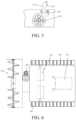
- the system of the snow blower 100 comprises a working module, a moving module, an energy module, a control module, a detection module and a man-machine interaction module, wherein the man-machine interaction module has a communication unit, and can receive a control signal sent by an intelligent device such as a remote control, a SMARTPHONE and an IPAD, these control signals are transmitted to the controller of the snow blower, and the controller can control the snow blower to advance, withdraw, steer, etc.
- the snow blower 100 can be provided with a camera, such that the remote control can be realized by the user indoors. If the camera is not mounted, the remote control can be realized by the user through direct observation.
- the above snow blower in the remote control manner does not need the detection module, and such manner is relatively simple, but needs all-time operation of the user.
- the preferable man-machine control manner in the present example is that the user remotely controls the snow blower 100 to advance to a start point of the working area, and then causes the snow blower 100 to automatically move and work by certain settings.
- These settings can be the setting of specific data such as a moving direction, a moving distance and a moving manner of the snow blower 100, and can also be the setting that the snow blower sweeps the snow according to a fixed shape, for example, a rectangle, a circle or other shapes, the snow blower automatically works according to the set graphic shape, and the like.
- the detection module at least comprises a direction detection device, for example, the sensor indicating the direction, such as an electronic compass or gyroscope, in this way, the user can set an advancing direction of the snow throwing machine and cause the snow throwing machine to move on a straight line.
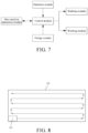
- the control module can set the start point position where the snow throwing machine begins to work as an original point to generate a border coordinate map according to the information (such as the length and width sizes) of the regular working area input by the input module, and the control module controls the snow throwing machine to regularly move and work within a border of the working area by using the direction detection device according to the border coordinate map. Specifically, as shown in Figs.
- the user manually inputs a snow removal area for example 4mX10m by the input module for example a remote control device or a built-in operation panel of the snow throwing machine, remotely controls the snow blower to advance to the start point or manually pushes the snow blower to the start point, and sets the position of the snow blower as the coordinate original point
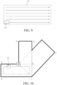
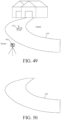
- the controller generates at least two snow removal paths according to the algorithms or programs stored in the control module and according to the data input by the user, one snow removal path is as shown in Fig. 8 and is the snow removal path of reciprocating along the length direction of a road, the other snow removal path is as shown in Fig. 9 and is the snow removal path toward one direction along the length direction of the road.
- the advancing times for snow removal can be automatically generated according to a width of the working head, for example, if the width of the working head is 0.5m and the set snow removal area is 4m wide, then the controller calculates that the advancing of at least 8 times is required.
- the user can select of the snow removal paths, and can also directly start the snow blower for working, that is, adopts the snow removal path of system default.
- the control module compares the received direction data with the selected snow removal path direction data, and controls the moving direction to adjust the moving direction when the two pieces of data are inconsistent, such that the snow throwing machine can move along the straight line.
- the controller can also calculate the moving distance of the snow throwing machine according to the rotary speed and the moving time of the driving wheels of the moving module, and controls the snow throwing machine to steer once the preset distance is reached, in one example,, the moving circle number N of the driving wheels and a perimeter L of the driving wheels are detected, and the moving distance is obtained by multiplying N by L.
- the moving distance of the snow throwing machine can be also be realized by setting a speedometer. The snow blower is returned back to the start point after the snow removal is finished, and the user can set another area for snow removal.
- the above man-machine controlled semiautomatic snow removal mode is suitable for the conditions of relatively simple working areas and regular roads
- the semiautomatic path can be set to be reciprocating or moving in the same direction, the moving in the same direction is intended to pile the snow to one side, while the reciprocating is intended to pile the snow to two sides, and after the working is finished, the snow blower can be returned back to the start point or directly stops.
- the user can set the direction of a fixed start point, so as to avoid the deviated moving caused by direction deviation after the snow blower is remotely controlled by the user to return back to the start point.
- the control module will control an advancing direction of the snow blower according to the direction detection sensor, and calculates the advancing distance, in this way, no artificial operation is required in the working process of the snow blower.
- the above setting can also be realized without the intelligent device such as the remote control, the SMARTPHONE and the IPAD, for example, the snow blower is provided with the operation panel per se, and the corresponding settings can be finished on the operation panel.
- Fig. 10 shows a relatively complex working condition
- the working area comprises three parts extending to three directions, when the snow removal area is set, the setting can be performed respectively according to the above method, that is, after the working of one area is finished, the another area is set, of course, there are more preferable solutions.
- the working area can be divided into three regular areas: OABCDO, OCEFO and ODGHO, wherein the intersection point O of the borders or the extending directions of the borders of the three areas is set as the base point, i.e., the original point, by using the snow sweeping path solution that the regular area uses the direction sensor and a regular parallel line mentioned in the above method, multiple areas can be set once, the snow blower is returned back to the original O after one area is completely swept, and sweeps another area after correction.
- Figs. 11 to 40 show a preferred second example, and the present example still takes the snow blower capable of automatically throwing snow as an example for explanation.
- the snow blower capable of automatically throwing snow comprises a working module, a moving module, an energy module, a control module, a detection module, a location module, and the like.
- the working module, the moving module, the energy module, the control module and the detection module are same parts as the foregoing example and are not repeated here.
- the difference from the foregoing example is that the snow full automatic snow removal work of the snow blower is realized in a location navigation manner.
- the snow blower is not always capable of or required for working in any places, and its working area has a boundary.
- the electric quantity of the energy module of the snow blower is insufficient, it is required to be supplied with electric energy in a fixed place and required to be parked in a place when not in work, that is, a dock.
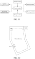
- the snow blower 100, a boundary 300 and the dock 500 form an automatic snow removal working system, wherein the boundary 300 is configured to limit the working area of the snow blower, the snow blower can move and work within or between the boundaries, and the dock 500 is configured to park the snow blower, and configured for the snow blower to return back for energy supplement when the energy is insufficient.
- the boundary is the joint name of a border and obstacles.
- the border is the periphery of the whole working area, and is usually connected end to end to close the working area, the border can be tangible or electronic, that is, the border can be a tangible border formed by a wall, a fence and handrails, or the border is a virtual border described on an electronic map or a border formed by the connecting line of N coordinate points, or a virtual border signal such as an electromagnetic signal or optical signal can be sent by a border signal generating device.
- the detection module of the snow blower 100 further comprises a boundary detection unit for detecting a relative position relation between the snow blower 100 and the boundary 300, which specifically and possibly comprises one or more of the distance, the angle, and the direction inside and outside the boundary.
- a boundary detection unit for example, an infrared manner, an ultrasonic manner, a collision detection manner, a magnetic induction manner, etc.
- the disposing positions and the amount of the sensors thereof and the corresponding signal generating devices are also multiple, are related to the path planning manners, and are thus specifically explained in combination with specific examples and path planning manners in the following.
- the dock 500 is usually located on the edge of a working range, is often located aside or on the boundary 300, and is connected to mains supply or other electric energy supply systems for the snow throwing machine to return for charging.
- the dock 500 comprises a base 510 and an outer cover 530 movably disposed on the base, the base 510 of the dock 500 is provided with a charging electrode 550, configured to be connected to the corresponding electrode of the snow blower 100.
- the outer cover 530 is open, and when the snow blower 100 enters the dock 500, the outer cover 530 is automatically closed to close the snow blower 100 within the dock 500.
- the outer cover 530 can be automatically closed along with the entrance of the snow blower, the structure is simple and the cost is low.
- the outer cover 530 can also be automatically opened and closed in an electrical control manner, for example, induction automatic doors (infrared induction, microwave induction, touch induction and pedal induction), and the automatic doors controlled by various signals to be automatically started and closed.
- a heating system can be disposed in the dock 500, a heating thermal insulation material can be arranged on the outside wall, the outer cover 530 or the bottom of the dock 500, or an air heater or an electric heating device such as an electric furnace and an electric heater can be disposed in the dock 500.
- a carbon crystal floor heating material 514 is embedded into the bottom of the dock 500, and can play a role of rapidly raising the temperature of an object, and 100% of the electric energy input is effectively converted into more than 60% of conducting heat energy and more than 30% of infrared radiation energy.
- a bottom plate of the dock is provided with an electric heating wire, or electric heating plate and temperature controller, internal constant temperature is realized by the temperature controller, and the heat can be effectively preserved by the thermal insulation material on the outer cover.
- the dock 500 is further provided with a snow sweeping device 580, configured to clean accumulated snow on the snow blower 100 when the snow blower 100 enters the dock 500.
- a snow sweeping brush is disposed on the edge of the outer cover 530 of the dock 500, and the snow sweeping brush can be controlled to rotate or be triggered by an external force to rotate.
- the snow sweeping brush is constructed as a rolling brush form.
- a rotary shaft of the rolling brush is approximately parallel with the ground, and a material of the rolling brush can be a soft material such as plastic, nylon and wool fabric.
- the rotation of the rolling brush can be automatically controlled, for example, the dock 500 starts the rolling brush to rotate once receiving the signal that the snow blower 100 is returned back for charging, or starts the rolling brush to rotate while the outer cover detects the snow blower and is opened for entrance of the same, or starts the rolling brush to rotate under the touch that the snow blower enters the dock, etc.
- the snow sweeping brush can also be constructed into a row brush form disposed along the edge of the outer cover 530. As the snow blower 100 moves to enter the dock 500, the row brush sweeps the top cover of the snow blower 100 to clean the accumulated snow on the top cover.
- the snow sweeping brush can also be multiple rotating brushes distributed on the edge of the outer cover 530, the rotary axis approximately forms an angle with the ground, and in this way, the accumulated snow on the top cover can also be cleaned when the snow blower 100 enters the dock 500.
- the snow blower 100 can also have the function of cleaning the accumulated snow on the top per se, for example, the top cover is inclined for an angle per se, the top cover can be disposed to regularly shake or to shake once detecting the accumulated snow, and a snow scraper, a hairbrush and the like can also be disposed on the top cover.
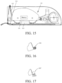
- the snow blower 100 needs to work during snowing or when there is accumulated snow, in order to realize the snow removal work of the full automatic mode, whether it snows and the snowfall need to be detected at first.
- a snow detector 102 is mounted on the top of the host of the snow blower, in one example, the snow detection 102 is pressure and humidity sensors, the sensors are better disposed in the highest position of the host 110, the pressure sensor is changed when there is accumulated snow, meanwhile the humidity sensor will detect the humidity change, the sensors feed the detected signals back to the control module, the control module judges whether it snows according to the signals, and calculates the snow thickness if it snows, and the snow blower 100 is controlled to begin to work when the snow thickness reaches a preset value.
- the preferred second solution is as shown in Fig.
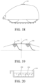
- the preferred third solution is as shown in Fig. 20 , a container 200 is provided and is provided with an optical sensor 202 and a humidity sensor 204 on the bottom, the container 200 is placed on the top of the host of the snow blower 100 or the dock 500, when the snow reaches certain thickness, and the optical sensor 202 cannot detect light while the humidity is changed, snow coverage is judged, and then the control module controls the snow blower 100 to begin to work.
- a preferred fourth solution is used for detecting the snow thickness. As shown in Fig.
- a weather communication unit receiving weather information in real time is disposed on the snow blower, the weather communication unit transmits the received weather signal to the control module, the control module judges whether it snows and the snowfall according to the received signal, and calculates the snow thickness according to the snowing duration.
- detection can be realized by sight glass, ultrasonic waves, infrared scanning sensors, etc., and the control module controls the snow blower to begin to work after certain time.
- the snow thickness can also be measured by camera image recognition, ultrasonic waves, etc., which are not repeated here.
- the working area of the snow blower is set in a DGPS manner.
- the snow blower when a border line 320 of the snow blower is generated, usually, the snow blower is controlled by manpower to move along the predetermined border line, the snow blower and the location navigation system are integrally mounted generally, and the location navigation system is non-removable.
- the location navigation system receives a location signal of the base station, the continuous coordinate points when the snow blower moves along the border line 320 can be obtained, and these coordinate points are connected into a line, i.e., the border line 320.
- the location navigation system is non-removable, in order to obtain the coordinate points of the border line, the snow blower must be moved per se, then the coordinate points of the border line can be obtained, but it obviously has the technical problems that the snow blower is heavier and larger, inflexible to move and hard to operate and control.
- the location navigation module can be constructed as a location navigation device 130 detached from the snow blower, meanwhile, the location navigation device 130 can also be remounted to the snow blower 100, that is, the location navigation device 130 is detachably mounted on the snow blower.
- the coordinate points of the preset border line can be obtained by the location navigation device 130 only, thereby generating the border line.
- the memory unit 132 is configured to store the location coordinate data of the location unit.
- the coordinate points obtained by the location unit 131 need to be stored in time, and for this, the location navigation device 130 needs to be provided with the memory unit 132 to prevent data loss.
- the sending unit 133 is configured to send the coordinate data stored by the memory module to the outside.
- the sending unit 133 can send the coordinate data of the border line to the outside timely, for example, to the snow blower.
- the sending unit 133 can be a wireless sending unit, and can also be a wired sending unit capable of being connected to a data transmission interface (comprising a USB interface, etc.) in the snow blower.
- the above location navigation device can be freely detached or mounted in the snow blower, and when the working border line of the snow blower needs to be generated, only the location navigation device needs to be detached from the snow blower, then the border line can be generated simply by the location navigation device, and the generation of the border line is facilitated.
- the location navigation device 130 can be freely detached from or mounted into the snow blower, in order to ensure connection steadiness when the location navigation device is mounted into the snow blower, the location navigation device 130 can be provided with an interface unit for fixedly mounting the location navigation device in the snow blower.
- the interface unit can be a socket or slot, and can be mounted into the snow blower.
- the location navigation device 130 further comprises a battery, configured to provide a power source for the location navigation device.
- the battery can be charged singly, and can also be charged by the snow blower after the location navigation device 130 is mounted in the snow blower.
- the snow blower 100 in the present example comprises the above location navigation device 130, and the control module thereof also comprises a receiving unit, configured to create connection with the sending unit 133 to receive the coordinate data sent by the sending unit 133.
- the receiving unit can be a wireless receiving unit and can also be a wired receiving unit corresponding to the sending unit 133.
- the memory of the snow blower is configured to store the coordinate received by the receiving module.
- the memory unit 132 in the navigation device 130 has stored the coordinate data of the border line, since the data are the data stored already, after the location navigation device 130 is mounted in the snow blower 110, the receiving unit can directly store the coordinate data read by the sending unit 133 from the memory unit 132 into the memory of the snow blower 110, so as to be convenient for the snow blower 110 to recognize the border line.
- the control module of the snow blower also comprises a detection control unit, which is configured to detect whether the coordinate data of the border line 320 stored by the memory are coincided with the coordinate data of the snow blower stored by the memory, and control the snow blower to move within the border line 320 when consistent.
- a detection control unit configured to detect whether the coordinate data of the border line 320 stored by the memory are coincided with the coordinate data of the snow blower stored by the memory, and control the snow blower to move within the border line 320 when consistent.
- the creation and storage of the map of the snow blower can be finished, thereby realizing the automatic navigation location of the snow blower
- the controller calculates the border data of the map according to the coordinate data of the border line stored in the navigation device, and generates map data
- the snow blower can be subjected to path planning according to the map, when the snow blower detects insufficient voltage or finishes once snow removal work, the snow blower will automatically store the current coordinates and navigation direction, and return back to the dock 500 for charging, after the charging is finished, the coordinates and navigation direction recorded last time are read, and the snow blower automatically plans the optimal path to reach the coordinate position and then continues to work.
- the above detachable location navigation device 130 can also be universal with other automatic moving devices, for example, an automatic mower, an automatic sweeper, etc., thereby improving the use rate of the location navigation device and reducing a purchase cost of the user.
- the location navigation adopted to set the working area of the snow blower is not limited to the above manner, the snow lower can also be provided with the location navigation module per se, the position coordinate data of real time location of the location navigation module are stored in the memory of the snow blower, the controller calculates the data of the map border according to the coordinate data of the border line stored in the memory, and generates map data, and then the snow blower can be subjected to path planning according to the map.
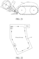
- Fig. 26 shows a schematic diagram of a house surrounding environment of the user of snow removal
- the user sets a mark on the intersection 330 on the map, for example, the shadow area in Fig. 28
- the size of the area along the sideway or an extending direction of the lane can be preset according to the sizes of the snow blower and the working head of the snow blower, or preset according to navigation errors, then the part of area is filled completely on the map of the working area, that is, the area is not required to be swept by default, and can be manually cleaned by the user, thereby preventing the snow blower from moving to the municipal road.
- the part of area can be artificially excluded outside the snow removal area when the border is set, that is, the nonworking area, and then the snow blower is prevented from moving to the municipal road.
- camera scanning can also be used, the intersection is swept if no vehicles are driven in a set distance, or sound-light alarm is started to warn the passing vehicles if the snow blower moves to the municipal road.
- the lawn needs no snow removal, and the user usually accumulates the swept snow on the lawn.
- the lawn is mostly distributed between the roads, after the map is generated according to the several aforesaid manners, the user can mark some areas on the map as the lawn, in the areas marked as the lawn, the user can select whether such the areas needs the snow removal or not, if the snow removal is not needed, then the machine can directly pass by the areas or the machine not move on the lawn, and if the snow removal is needed, then the snow removal mode or snow removal height can be set to avoid the damage to the lawn.
- the user can set a passage from one snow removal area to another snow removal area, in general cases, the user is suggested to set the passage on the lawn, for example, the area as shown by a virtual line in Fig. 27 is the connecting passage 360 of two snow removal areas, since whether the grass area needs the snow removal or not or the snow removal mode and the snow removal height have been set, extra setting is not required here.
- the user can further set whether the path needs the snow removal or not here.
- the snow blower can pass by one snow removal area to reach another snow removal area.
- the municipal rod can also be selected as the passage, correspondingly, the moving path from one intersection to another intersection needs to be set, for example, the snow blower moves along the border of the municipal road, and performs light-sound alarm to gain the attention of pedestrians and passing vehicles, and compared with the passage in the lawn, the municipal road as the passage is a secondary manner.
- a more precise manner is that when the working area is set, the user holds the location navigation device 130 to move for a circle around the island, and such area is defined as the island i.e., the non-snow removal area after the map is generated.
- map generating manner will be different if the island setting manner is different, but the basic principle thereof is similar, or exclusion is performed when the working area is set or is performed on the generated map, no matter what kind of manner, the areas can be defined on the map, such that the snow blower selects whether to work or the working mode according to the defined areas.
- the snow blower is provided with an alarm lamp, and pedestrians and the user can be warned and reminded in a full bright or flickering manner.
- the user can mark the alarm area or set the alarm time on the map, and the controller in the snow blower can alarm according to the setting of the user after the snow blower reaches the set area and the set time is reached or the set requirements are met at the same time.
- snow removal manners usually, snow sweeping, snow pushing and snow throwing.
- the setting of special scenarios here refers to that if the snow removal manner is the snow sweeping or pushing, then a snow piling point needs to be set; and if the snow removal manner is snow throwing, then a snow throwing direction needs to be set.
- the snow sweeping is to clean the snow to the front of the snow blower by a rotating rolling brush
- the snow pushing is to push the snow to the front of the snow blower, therefore, during snow pushing, the snow in front of the snow blower will be thicker and thicker, in order to prevent such case, the snow blower can be set to push the snow to a set position, i.e., the snow piling point, every time the snow blower pushes the snow for a certain distance.
- the snow throwing is to roll the snow into the snow blower by an auger and then throw out by a snow throwing cylinder, and the case that the snow is thrown to neighbor's home or the municipal facilities such as a mailbox is not allowed, then the snow throwing direction needs to be set.
- the snow removal manner is snow sweeping or snow pushing
- whether the user needs to set the snow piling point personally will be automatically reminded by the system, if yes, the user needs to set one or more snow piling points, then the snow blower will calculate the path according to a snow sweeping or snow pushing area, and if the snow piling points are too less, then user is reminded of increasing the snow piling points. If the user selects no need of setting, then the controller will calculate the path according to the snow sweeping or snow pushing area and automatically plans the snow piling points.
- the user can form different marks on the map according to the areas, for example, a motorway, a sideway, etc., different marks have different working modes, for example, the snow throwing is performed on the paths marked as the motorway, and the snow pushing or snow sweeping is performed on the sideway, or a thick snow removal mode is performed on the motorway and a thin snow removal mode is performed on the sideway; or the user can set the snow throwing or snow pushing mode.
- All above setting can be performed on the operation panel of the snow blower, or can be remotely operated on mobile devices such as the mobile phone and a computer, and then operation is performed by the remote control of the snow blower per se.
- the communication manner between a control end and a terminal of the remote control operation can be WIFI communication, Bluetooth communication, Zigbee communication, radiofrequency communication, etc., or the communication between the control end and the terminal can be realized based on a cellular network.
- the snow blower can be started to work. Next, the path planning when the snow blower is in work is explained in detail.
- the moving path executed by the snow blower is also different to some extent.
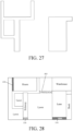
- the snow throwing path is generally parallel with an extending direction of the road, and the snow blower moves along an S path and throws the snow out by a snow throwing cylinder.
- the controller in the snow blower can control the snow throwing cylinder to rotate, which can at least rotate for 360 degrees.
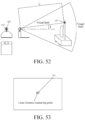
- the snow throwing path if the snow throwing direction is defined, that is, the snow throwing surface as shown in Fig. 30 , then the snow throwing cylinder will rotate according to the moving path of the snow blower, such that a snow throwing opening of the snow throwing cylinder always throws the snow to the snow throwing surface.
- the snow throwing direction is generally vertical to the moving road surface.
- the snow throwing path can also be that the snow blower moves along one direction and throws the snow, and is retuned back on the path which has been subjected to snow removal and only moves without snow throwing, or the snow throwing direction is not required to be adjusted.
- the control module needs the distance from the snow blower to the snow throwing surface to calculate the snow throwing distance, and the snow throwing distance can also be changed by adjusting a rotary speed of the snow throwing wheel.
- the snow throwing cylinder throws the snow by rotation
- the controller of the snow blower will recognize the rotating current, a rotary speed and the like of the motor, when the current exceeds a set threshold or the rotary speed is lower than the threshold, it is indicated that the thrown snowfall is overlarge, and the snow blower will avoid the overload of a snow throwing motor by reducing the moving speed.
- Fig. 32 shows the first snow sweeping path
- the snow sweeping path can be vertical to an extending direction of the road, or parallel with the extending direction of the road
- the solid line shows the snow sweeping path
- the virtual line shows a repeating path or returning path
- the first path has the characteristic of snow sweeping toward one direction and is suitable for the road of which both sides are the snow lands, but the snow can only be thrown to the lawn on one side, thereby avoiding that the snow is thrown to the lawn on the other side during snow sweeping.
- the returning path has been swept, repeated sweeping is not required, and from the moving path of the snow blower, the snow blower moves for two road sections, but actually sweeps one road section, the sweeping efficiency is general and the first path is not suitable for the occasions requiring fast snow removal.
- Fig. 33 shows a second snow sweeping path
- the snow sweeping path is vertical to the extending direction of the road
- the snow is swept to two sides, that is, the snow can be swept for all the paths where the snow blower moves
- the second snow sweeping path can also be called as S path snow sweeping and is suitable for the condition that both sides of the road are lawns and the snow can be thrown to the both lawns
- the snow sweeping path is vertical to the extending direction of the road, the sweeping distance once is short, not too much snow will be accumulated in front of the snow blower, therefore, the sweeping is not required to be performed to specific snow piling points, no repeated paths exist, and the snow sweeping efficiency is higher.
- Fig. 34 shows a third snow sweeping path, the snow sweeping path is parallel with the extending direction of the road, and is also S path snow sweeping, and such snow sweeping manner has the least turning times and the relatively high in efficiency.
- Fig. 35 shows the first snow pushing path
- the snow pushing path is approximately parallel with the extending direction of the road, since the snow pushing distance is longer, two snow piling points need to be set
- the solid line shows the snow pushing path
- the virtual line shows the repeated path or the returning path
- the first path has the characteristic that the snow blower pushes the snow to the snow piling point from the first position of one direction and is then retuned, then pushes the snow to the snow piling point from the second position of such direction, and so on till the snow on the whole width of the road is cleaned, and then the snow blower pushes the snow to the next snow piling point.
- Such manner is suitable for the situation that the snow can only be piled to fixed places.
- Fig. 36 shows the second snow pushing path
- the snow pushing path is approximately vertical to the extending direction of the road
- the snow blower pushes the snow to two sides respectively from the middle of the road
- one choice is that the snow blower pushes the snow to one side, is returned to the middle and then pushes the snow to the other side, and so on
- the other choice is that the snow blower pushes the snow to one side from the middle, is retuned to the middle, then continues to push the snow to such side till the tail end of the road, and then pushes the snow to the other side from the middle of the tail end, i.e., from the head to the end for half of the road and from the end to the head for the other half of the road.
- Such path is suitable for the situation of the wider road, and the situation that the user does not set the snow piling point and the snow can be piled to both sides of the road.
- Fig. 37 shows the third snow pushing path
- the snow pushing path is approximately vertical to the extending direction of the road
- the snow blower pushes the snow in an S shape from one side of the road, and such manner is suitable for the situation that the once maximal snow pushing amount along the width of the road is smaller than the load of a snow pushing machine, wherein the maximal snow pushing amount can be calculated according the snow thickness, the road width and the length of a snow pushing head.
- the number of the snow piling points is related to the length of the snow pushing path, and each snow piling point requests that the moving path cannot be too long to avoid the overlarge snow pushing load.
- the controller of the snow blower will calculate whether the snow piling points set by the user meet the requirements or prompt the user to set sufficient snow piling points.
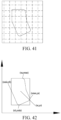
- a dip angle of each point will be recorded simultaneously, as shown in A1, B1...N1.
- the snow blower works according to the path, it will judge whether the dip angle of the front path is overlarge or not, that is, the snow blower will judge the dip angle of the B1 point when at the point A1, the working head will be affected if the dip angle of the B1 point is overlarge, that is, if the dip angle of the B1 point is larger than a preset value, the controller will start the motor to lift the working head for certain angle in advance.
- the lifted angle is related to the B1 point, and the larger the dip angle is, the larger the lifted dip angle is. After the dip angle is restored to be normal, the controller starts the motor again to descend the working head.
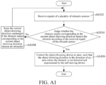
- the detection system of the snow blower further comprise an obstacle sensor, and the obstacle sensor can be an ultrasonic sensor, an infrared sensor, a laser sensor, a radar, a camera, etc.
- the obstacle sensor detects the obstacle, if the working head is the snow pushing head or the snow sweeping head, then the snow pushing head or the snow sweeping head will stop working or work toward the places without the obstacle. If the working head is the snow throwing head, the snow throwing direction will be changed.
- the snow blower according to the present examples can be automatically returned back to the dock for charging according to self conditions.
- the controller in the snow blower can calculate the energy of the battery and the working time, when the energy of the battery is lower than a preset value or the working time is larger than the preset value, the snow blower is controlled to be returned back to the dock.
- the returning path of the snow blower is divided into two manners, the first manner is as shown in Fig. 39 , the solid line path is the path that has been swept, and the virtual line is the returning path. The returning path has been in the swept path, therefore, the snow sweeping head does not work during returning, thereby saving returning energy.
- the second manner is as shown in Fig. 40 , the solid line path is the path that has been swept, the virtual line is the returning path, the returning path is contained in the snow sweeping path, i.e., the snow sweeping is performed during returning.
- the controller of the snow blower will automatically calculate the required working area and required energy, when the energy is enough to support the working area required by once sweeping, the second solution is adopted, when the energy is not enough, the first solution is adopted, and the benefit of adopting the second solution will save more time compared with the first solution.
- the dock is provided with a wireless charging emitting panel
- the snow blower is provided with a wireless charging receiving panel
- the wireless charging receiving panel is connected to a battery in the snow blower
- the controller realizes the connection between the wireless charging emitting panel and the wireless charging receiving panel by guiding the snow blower to move through the location navigation module.
- the detection system of the snow blower further comprises a signal detection circuit, when the snow blower moves to the dock, the wireless charging emitting panel sends a charging signal to the wireless charging receiving panel, the signal detection circuit detects whether the intensity of the charging signal received by the wireless charging receiving panel reaches the preset value, locates the position of the wireless charging receiving panel when the intensity of the detected charging signal reaches the preset value and guides the snow blower to stop moving for wireless charging.
- the charging signal can be a current or voltage signal
- the signal detection circuit detects whether the current or voltage generated on a charging loop by the charging signal received by the wireless charging receiving panel reaches the preset value in real time to judge whether the intensity of the charging signal reaches the preset value.
- the wireless charging emitting panel in the present example is provided with sensors for detecting the snow and snow weight, and a heating system. After the snow blower is returned and the wireless charging emitting panel and the wireless charging receiving panel are jointed, the weight on the emitting panel will be detected, if the weight exceeds the threshold, the heating system will be started to melt the accumulated snow. After the weight is lower than the threshold, the snow melting is stopped.
- the snow blower By detecting the snow, the snow blower will automatically go out of the dock for snow removal when it snows or the snow thickness reaches the preset value, i.e., user monitoring is not required after once setting is finished.
- the snow blower can also receive the information such as weather report and real time weather by a network, and makes a working plan.
- the snow blower can send the working area, a cutting solution and the like of the user's house to a cloud terminal, and the cloud terminal can optimize the sweeping solution of the snow blower according to the data such as situation, terrain and climate of the user and users around.
- the data of the snow blower can be interconnected with the smart home in the house by the cloud terminal, for example, after detecting the snowing, the snow blower will send the data to the cloud terminal, and the could terminal closes windows and switches on an air conditioner of the user and controls the snow blower to go out for working by the smart home.
- the snow blower can serve as part of an intelligent gardening system, the intelligent gardening system is configured to inspect and control gardening devices in a gardening area, and its control center generates a control instruction based on the environment information of the gardening area collected by the sensors, and the snow blower executes the snow removal working according to the control instruction.
- the gardening devices such as the sensors and the snow blower and the control center intercommunicate with each other to form internet of things.
- the manufacturers will pave the border line of the working area of the snow blower where the snow removal is required according to the requirements of the user, the border line is paved by some large-scale machinery capable of slotting and sinking cords, or slotting is performed by some electric or manual tools, and then the border line is manually placed in slots.
- the border line is an electrified wire, a specific border line signal exists in the wire, the border line signal is sent from the dock, and the snow blower can recognize whether the snow blower is inside or outside the border line by receiving an electromagnetic signal sent by the border line through an induction coil mounted in the snow blower.
- the snow blower can apply the electronic compass, the speedometer and the GPS to realize automatic location and navigation, a course angle is measured by the electronic compass, then the relative coordinates of the snow blower are obtained in combination with the dead reckoning of the speedometer, then absolute location and error elimination are performed according to the GPS coordinates, and finally the coordinates of the snow blower at any moment can be obtained.
- a preferred method for constructing and storing the map of the snow blower in the present example comprises the following steps:
- map grid attributes in the step 5 are formed by multiple elements related to the map of the snow blower, and comprise the attributes for representing the environments in the map grids and the attributes for representing whether the snow blower passes by the map grids.
- the method of the system can finish the creation and storage of the map of the snow blower, thereby realizing the automatic location navigation of the snow blower.
- the snow blower firstly operates for a circle around the working area, calculates the data of the map border according to the coordinate values calculated by the sensors and generates a mapping relation between the map data and the address of the storage unit, then the snow blower creates internal map data within the border area and updates the map attributes in the memory.
- the snow blower After the map coordinates are created, the snow blower operates according to the map, the snow blower reads the data of the current coordinates and of adjacent four coordinates by location, and the next action and the operation direction of the snow blower are judged according to the advancing direction and the grid properties of the adjacent coordinates, when a working voltage of the snow blower is not enough, the sown blower automatically stores the current coordinates and the navigation direction and is retuned back to the dock for charging, reads the coordinates and the navigation direction recorded last time after the charging, automatically plans the optimal path to reach the coordinate position, and then continues to work.
- the snow blower creates the map data by the location navigation sensors and enables the map data and the addresses of the storage unit to be in one-one mapping, thereby conveniently storing and reading massive map data.
- the map data of the snow blower in the above method are in the grid form, the map environment can be better described by using the attributes of the grid map, in view of the reason of larger data size of the grid map, when the map is created, the snow blower departs from the dock and operates around the border line, continuously calculates the current coordinates in the operation process, and obtains the four important characteristic coordinate points representing the map size after operating for one circle, which respectively comprise the two points with the maximal and minimal horizontal coordinates of the map and the two points with the maximal and minimal longitudinal coordinates of the map, then the mapping relation between the map data and the addresses of the map data is automatically created according to these four characteristic coordinate points, the map data and the memory unit are tightly combined by creating the address mapping, not only is the rapid reading and storage of the map data realized, but also the method is suitable for the maps of different sizes by adopting a parameter adjusting manner, such that the snow blower can operate under any working environment.
- the map data After the map data are created by such method, the map data have uniqueness, that is, the contents of the memory unit correspond to the coordinates of the whole environment map one to one, when the snow blower needs to call the map in the operation process, the map data can be rapidly read by only calculating the parameter in the map corresponding to the current coordinates, thereby ensuring that the snow blower has a clear understanding on the environment map.
- Another manner adopted for setting the working area of the snow blower is UWB, to generate the border map.
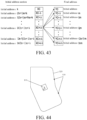
- the location system of the snow blower comprises a border 320 defining the working area of the snow blower 100, UWB labels 410 are disposed outside the working area, the outer part of the working area comprises a border line 320 and the two UWN labels 410 outside the border line 320, the location navigation module of the snow blower is a UWB location module, and the UWB location module calculates the two positions of the snow blower by the two UWB labels 410, and takes the position in the border line as the position of the snow blower.
- the UWB location module sends a UWB signal to the UWB labels 410 to wake the UWB labels 410, the UWB signal is fed back to the UWB location module after the UWB labels 410 are waked, the UWB location module sends a location UWB signal to the UWB labels 410 after receiving the fed UWB signal and starts timing, the UWB labels 410 send a location feedback signal to the UWB location module after receiving the location UWB signal, and the UWB location module stops timing after receiving the location feedback signal and calculates the position of the snow blower 100.
- Fig. 45 has two UWB labels 410.
- the outer part of the working area comprises a border line 320 and an outer part of the border line 320, two UWB labels can be disposed on the border line 320 and can also be disposed outside the border line 320, or one UWB label is disposed on the border line 320 and the other UWB label is disposed outside the border line 320.
- the two UWB labels 410 as shown in Fig. 45 are disposed on the border line 320.
- a border line receiver can be disposed in the snow blower 100, and the UWB location module can judge whether the position of the intersection point is in the working area according to a border line signal received by the border line receiver.
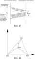
- Fig. 46 has three UWB labels 410 which are not on the same straight line, when the three UWB labels 410 are disposed, one, two or three of the labels can be disposed outside the border line 320.
- the three UWB labels 410 as shown in Fig. 46 two UWB labels are disposed on the border line 320, and one UWB label is disposed outside the border line 320.
- the UWB location module when the UWB location module receives the location feedback signal and then stops timing and calculates the position of the snow blower 100, the UWB location module respectively calculates the distances r1, r2 and r3 between the snow blower 100 and the three UWB labels 410 according to the sent location UWB signal and the time duration between the time of timing starting and the time of timing stopping, three corresponding circles are made with the calculated distances r1, r2 and r3 between the snow blower 100 and the three UWB labels 410 as the radii, and with the positions of the corresponding UWB labels 410 as the circle centers, and the calculated position of the intersection point of the three circles is used as the position of the snow blower 100. As shown in Fig. 46 , the three circles have only one position of the intersection point in common, and the position of the intersection point is the position of the snow blower 100.
- Respective UWB labels are respectively disposed on the border of the working area or in multiple preset positions on the lawn aside, are easier to mount and are closer to the UWB location module, which is favorable for the UWB location module to find the position per se.
- the UWB signal sent by the UWB location module is a low level signal.
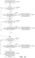
- the above self location method for a snow blower comprises the following steps:
- the waking signal, the waking feedback signal, the location signal and the location feedback signal are all UWB signals, and rapid distance measuring is realized by using the UWB location module and the UWB labels.
- the step of sending a location signal to respective UWB labels by the UWB location module, and starting timing comprises the following step: sending the location signal to respective UWB labels by the UWB location module, and starting timing for respective UWB labels respectively.
- the step of calculating the distances with the respective UWB labels by the UWB location module according to the timing results comprises the following step: after the UWB location module receives the location feedback signal sent by one UWB label, stopping timing for such UWB label, and calculating the distance with such UWB label according to the timing result.
- the UWB location module sends the location signal to each UWB label and respectively starts timing for each UWB label; after receiving the location feedback signal sent by certain one UWB bale, the UWB location module stops the timing for such UWB label, and the UWB location module can calculate the distance with such UWB label according to the timing result specific to the certain one UWB label. Therefore, according to the timing result for each UWB label, the distances between the UWB location module and the respective UWB labels can be calculated.
- the step of calculating the distances with respective UWB labels according to the timing results comprises the following step:
- a specific distance measuring method of the ultra wide band comprises time of arrival (TOA), time difference of arrival (TDOA) and roundtrip time of flight (RTOF), etc., wherein the RTOF is taken as an example for explanation.
- TOA time of arrival
- TDOA time difference of arrival
- RTOF roundtrip time of flight
- T R is the time that the signal is transmitted to B from A
- T A is the total time from the time of starting timing to the time of stopping timing for the UWB label by the UWB location module, that is, the signal total time in the measuring process
- the distances between three auxiliary location devices are measured at first, the connecting line of two of the location devices is taken as an x axis, then a mathematic model as shown in the figure can be simplified, wherein the point D (x, y) represents the UWB location device assembled on the snow blower, while A(0, 0), B(k, 0) and C(m ,n) are the coordinates of the three auxiliary location points (corresponding to the three UWB labels in the present examples).
- the coordinates of the three points can be measured by the distances between the points A, B and C.
- the method comprises the following steps:
- the UWB location module After moving respective UWB labels, the UWB location module sends the location signal to the respective UWB labels and starts timing, the respective UWB labels send the location feedback signal to the UWB location module respectively, and the UWB location module stops timing after receiving the location feedback signal.
- the distances with the respective labels are calculated according to the timing results, thereby locating the position of the snow blower.
- the automatic location of the snow blower is realized and further the path planning is performed.
- Another manner for setting the working area of the snow blower is to circle on an electronic map, for example, Google map.
- the user loads the electronic map such as the Google map by a mobile phone, a remote control and other manners.
- the mobile phone or computer has a GPS or WIFI location module and the like, by which the user can rapidly find the position of own home on the map.
- the user circles one working area, and the mobile phone or the computer guides the working area into a controller of the snow blower and generates a map as shown in Fig. 41 .
- a reasonable snow removal path is processed and planned in the border of the area needing snow removal by path planning.
- the location navigation function may not be adopted, the working area of the snow blower is set in a remote control extraction manner, and the working area is recognized based on a video manner.
- the whole automatic snow removal system comprises the snow blower and a monitoring device 600 such as a SMARTPHONE or IPAD for monitoring a working state of the snow blower
- a man-machine interaction module of the snow blower comprises a wireless communication unit, the wireless communication unit is connected to the control module and configured to receive a signal sent by the monitoring device such as the SMARTPHONE or IPAD and transmit the signal to the control module, and the control module controls a moving direction, a moving speed, the working state and the like of the snow blower 100 according to different signals.
- the monitoring device 600 such as the SMARTPHONE or IPAD is fixed by a support and is disposed in a place capable of shooting the whole working area, firstly, a vision field is adjusted, then the picture of the working area is shot, that is, the area is determined; then the user describes the working area on the picture of the working area, i.e., area extracting, to obtain a border line 320', and the extracted working area is as shown in Fig. 40 .
- Figs. 51 to 53 show a third example, which is a solution of border setting and path planning by a three-dimensional polar coordinate solution, i.e., a manner of image tracking, laser distance measuring and angle measuring of a machine-identified object.
- the snow removal system in the present example comprises a snow blower 100 and a fixed site 800.
- the fixed site has a detection module and a site wireless communication module, wherein the detection module comprises a laser distance measuring module 820, a cloud deck camera 840 and a sensor configured to measure an angle (for example, a triaxial acceleration sensor), and correspondingly, the snow blower is provided with an obvious identified object 191 and a machine wireless communication module, wherein the cloud deck camera 840 can rotate for 360 degrees horizontally and can rotate for 180 degrees up and down, and the laser distance measuring module 820 is mounted aside the camera.
- the could deck is further provided with an angle sensor (not shown), the angle sensor, the camera 840 and the laser distance measuring module 820 are relatively static.
- the site wireless communication module on the fixed site can communicate with the snow blower.
- the top of the snow blower is provided with the identified object 191 having an obvious mark (for example, a specific color or specific shape, or a partially lighting object), the size of the identified object is very small relative to the snow blower, and can be conveniently subjected to image identification.
- the machine wireless communication module mounted on the snow blower can communicate with the fixed site.
- the setting manner for the working area is as follows: enabling the snow blower to be on the fixed site, and enabling the camera to face front as an original point of the three-dimensional polar coordinates; remotely controlling or hand-pushing the snow blower for a circle along the border to be swept, and ensuring that no people or other objects shield the snow blower from identifying the identified object in the advancing process; adjusting the camera on the fixed site in such process, such that the image of the identified object and a light spot of the laser distance measuring module of the snow blower are aligned with a central area of the image of the identified object, at this point, recording the laser distance measuring distance L, and a planar offset angle ⁇ and a vertical angle ⁇ of the camera, thereby obtaining the three-dimensional polar coordinates of the snow blower in such position.
- a continuous border track can be obtained by multipoint sampling to form a closed border.
- the GNSS needs well receiving of a satellite signal to work reliably.
- the satellite signal is blocked by a building, a roof, a sunshade, leaves or a tree sometimes.
- a target receiver can be used in short distance, which is so-called differential GNSS.
- differential GNSS There are some differential technologies, for example, the typical DGPS (or GPS), RTK and wide range RTK (WARTK).
- the signal from one signal may also be stopped, for example, the case that the garden or other working areas are just around the house.
- position determining devices also have the similar problem, for example, when an optical beacon is used, the sight may be blocked in certain areas. If the snow blower cannot correctly receive the signal from the position determining system, it will face a challenge, and cannot be correctly navigated in the working area and the coverage of the working area may not achieve the expected effect.
- the snow blower may also adopt an inertia navigation system per se for navigation work, but according to the working principle of an inertia navigation system (the working principle of the inertia navigation is that based on the Newtonian mechanics laws, the accelerated speed of a carrier in an inertia reference system is measured and is integrated subject to integration to time, and it is converted into a navigation coordinate system to obtain the information such as a speed, a yaw angle and a position in the inertia navigation system).
- the inertia navigation system belongs to a calculation navigation manner, and the precision must be reduced along with time, which is not favorable for the long term work of the snow blower.
- the working area has no border line, for example, the position kept in the working area by using the location system (for example, GNSS), and the working area is defined by coordinates.
- the location system for example, GNSS
- the snow blower is provided with a position determining device, for example, a GNSS device.
- the GNSS device is a GPS device.
- the GNSS is connected to the controller, such that the controller can determine the current position of the snow blower and controls the movement of the snow blower with the GNSS device based on the current position.
- the position determining device comprises an optical (laser) position detection device, other wireless frequency position detection devices, a UWB signal station, a receiver, etc.
- the snow blower is further provided with at least one sensor, configured to provide a signal for dead reckoning.
- Such dead reckoning navigation sensor can be a speedometer, an accelerator, a gyroscope, an electromagnetic compass, a magnetometer, a compass, etc.
- the controller can determine that the received signal is reliable, and responds to execute the determined working mode.
- the controller executes the operation of continuously using another navigation system, or determines an alternative snow removal mode, that is, the location detection mode is not required.
- the dead reckoning navigation is switched, the calculation work is derived, and the final known position and direction are adopted as the current position and an assumed direction, for example, the current position is determined by measuring the amount of rotating wheels (or, the rotary speed and time of a rotary shaft).
- the deriving technologies for calculation also comprise relative navigation of other manners, for example, a visual/optical navigation system, SLAM, fingerprint fusion, and the like.
- the generated operation mode B may be different from the GNSS-based operation mode, due to the error of the sensor device, the compass or speedometer is configured for dead reckoning navigation.
- the controller calibrates the dead reckoning navigation sensor when the snow blower can reliably receive the GNSS signal.
- the controller detects the derived calculation navigation error and the calculation navigation sensor derived in response to the error calibration.
- the controller determines no navigation errors based on the difference between the current position and the expected position by comparing the current position and the expected position.
- Fig. 54 takes the parallel lines as an example of the path of the snow blower in the working area, the snow blower moves in the working area under guiding of the signal received by the GNSS device, and the moving parallel lines are equal in length.
- the snow blower enters the interruption area, the controller switches to dead reckoning navigation, and the snow removal paths B generated thereby are almost parallel lines.
- the snow blower reenters the GNSS navigation area, in other words, when the reliable signal is received again, the current position and the expected position are compared.
- the C point is the position where the snow blower reenters the GNSS navigation area, and at this point, the snow blower reenters the GNSS navigation area to determine the distance ⁇ between the current position and the expected position.
- the expected position is determined according to the time that the snow blower loses the GNSS navigation, a moving average speed and snow removal work parameters (or operation mode).
- the dead reckoning navigation sensor will calibrate the snow removal path generated thereby, for example the position D in the figure, more similar to the snow removal path under the GNSS navigation. As the snow blower is returned back to the GNSS area, for example, the position E in the figure, the snow blower will approach to the expected position.
- the snow blower can still execute and finish the work according to requirements.
- the working module can also comprise one or more of a working head mechanism such as a snow sweeping mechanism 120 and a snow pushing mechanism 160, and working motors driving these mechanisms to work, and may also comprise a snow sweeping/pushing height adjusting mechanism.
- a working head mechanism such as a snow sweeping mechanism 120 and a snow pushing mechanism 160
- working motors driving these mechanisms to work
- the working head mechanism can be replaced according to needs, or automatically replaced.
- the snow blower 300 comprises a host 110 and one or more of the snow removal mechanism 120, a snow throwing mechanism 140 and the snow pushing mechanism 160 which are detachably matched with the host 110, the host 110 of the snow blower 200 is provided with different working head mechanisms to correspondingly execute the working modes, that is, if the host 110 is provided with the snow removal mechanism 120, correspondingly, the snow blower 100 executes the snow sweeping mechanism; if the host 110 is provided with the snow throwing mechanism 140, correspondingly, the snow blower 100 executes the snow throwing mechanism; and if the host 110 is provided with the snow pushing mechanism 160, correspondingly, the snow blower 100 executes the snow pushing mechanism.
- Different snow removal modes correspond to different working conditions, for example, the snow sweeping corresponds to a thin snow condition, the snow pushing corresponds to a moderate or thick snow condition, the snow throwing is suitable for the snow of various thicknesses, in one example,the snow throwing is suitable for the moderate or thick snow condition.
- the snow throwing machine is taken as an example for explanation, of course, those skilled in the art can perform simple replacement, the foregoing example can also be a snow sweeper or snow pusher, that is, other modules can be referred as long as the corresponding working heads are different.
- the specific working head is as shown in Fig. 55 , the working head mechanism is a snow sweeping mechanism, the snow sweeping mechanism 120 comprises a rolling brush 122, a protective cover 124 mounted on the periphery of the rolling brush 122 and a working motor driving the rolling brush 122 to rotate (not shown in the figure), and the rolling brush 122 rotates at high speed along with the advancing of the snow blower 100, thereby sweeping the snow to the front of the snow blower 100.
- the working motor can drive the rolling brush to rotate by some common transmission mechanisms, such as a conical gear mechanism and a turbine worm mechanism.
- the rotary speed of the rolling brush 122 is smaller than 1000 r/m ,in one example, the rotary speed issmaller than r/m.
- the material of the rolling brush is mostly nylon and can also be a nonmetal material such as plastic, rubber and a wool fabric to prevent the injury to people during mistake collision.
- the rotary direction of the rolling brush 122 can be the clockwise direction or the counterclockwise direction, and if the rotary direction is different, the snow throwing direction and distance will be different to some extent. As shown by an arrow direction in Fig.
- the rolling brush 122 rotating at the high speed carries the snow to be thrown out from the upper side of the rolling brush, and if along an opposite direction of the arrow, the snow will be thrown out from the lower side of the rolling brush 122.
- the protective cover 124 extends for a distance to the front part of the rolling brush along a tangential direction to form a protective plate 1242, which can guide the snow rotated along with the rolling brush 124 to be thrown out to the lower side.
- a snow throwing angle ⁇ of the protective plate 1242 relative to the vertical direction is between 20°-70°, which not only prevents the snow from being blocked in the protective cover 124 but also ensures the snow throwing safety without affecting the snow sweeping efficiency.
- the foregoing three working head mechanisms can all be detachably mounted on the host 110 of the snow blower 100.
- a connecting part 112 is disposed on one side of the host 110, the connecting part 112 is provided with a power supply interface, correspondingly, the snow removal mechanism 120 and the snow throwing mechanism 140 have corresponding power supply interfaces, while the snow pushing mechanism 160 needs no power supply and does not need to be provided with the power supply interface, therefore, the electric connection with the host can be realized by connecting the snow removal mechanism 120 and the snow throwing mechanism 140 to the connecting part 112, and its working motor is powered by an energy module in the host.
- the three working head mechanisms, i.e., the snow removal mechanism 120, the snow throwing mechanism 140 and the snow pushing mechanism 160 are in pivoting connection with the host 110, are connected by dowels or bolts and can pivot relative to the host 110.
- the snow blower also has a function of automatically recognizing the working head, as shown in Fig. 58 , the connecting parts between the three working head mechanisms and the host are respectively provided with recognizing devices in different positions, the recognizing devices can be constructed as magnets, or triggering switches or communication interfaces, etc., different working head mechanisms are connected to the host to generate different signals which are fed back to the control module, the control module judges the forms of the working heads according to the received different signals and automatically executes the control manners corresponding to the working heads, for example, adjusting a motor rotary speed, a moving speed, etc.
- the connecting part 112 of the host is provided with three signal switches 114, the connecting part between the snow removal mechanism 120 and the host can trigger the first signal switch, the connecting part between the snow throwing mechanism 140 and the host can trigger the second signal switch, the connecting part between the snow pushing mechanism 160 and the host can trigger the third signal switch, according to the different triggered signal switches, the control module executes the control mode corresponding to the received triggering signal.
- the snow blower is provided with three working head mechanisms, and at least two signal switches can be disposed to realize the recognition of the three working heads. Of course, more working heads can be configured according to the needs, and correspondingly, multiple signal switches are disposed to recognize different working heads.
- the manner of a communication mode can also be used, that is, a PCB is disposed in the working head and can communicate with a main control part, and can notice the main control working head of the type of the module in a communication manner.
- an electric heating thermal insulation material 130 for example, a solid electric heating cake filled with heat preservation cotton (for example, asbestos, etc.), and the thermal insulation working principle is that a dual-temperature control electric heating energy storage structure is used to gradually release the heat energy.
- An automatic overheating protective device and an automatic thermal insulation indication device a small electric furnace controlled by a PTC thermosensitive resistor switch are disposed internally, the PTC is the thermistor of a positive temperature coefficient, when the current passes, the thermistor will emit heat (the heat of the electric furnace is also conducted thereto), when the temperature reaches a certain value, the thermistor is increased severely in resistance and can be regarded as disconnection, at this point, the consumption of the electric energy is stopped, then the slow heat release is realized depending on the thermal insulation of the heat preservation cotton, and the thermal insulation time is long. In this way, the snow blower can be heated only during charging and then the host is subjected to thermal insulation by the electric heating thermal insulation material, thereby preventing the elements and parts such as a battery and the controller from working under the low temperature state.
- the electric heating thermal insulation material 130 can also be liquid, an electrode heating method is adopted, and double temperature control security of high quality temperature control and a thermal fuse is adopted.
- the temperature controller will automatically cut off the circuit when the liquid temperature reaches 65 degrees in a normal case, heating is stopped, and the temperature of the heat by contact of chemical substances therein is about 40°C.
- a liquid energy storage heating agent is used, the heating temperature rise is fast, the liquid is added once and can be used permanently, and the advantages of long service life and durable temperature preservation are realized.
- the function of a lithium battery can be used, an internal heating piece heats, and the temperature can reach about 50°C.
- the first solution is to dispose an obstacle sensing component such as an obstacle detection device on the snow throwing machine, and the control module controls the snow throwing component 144 to throw the snow to the area without people or objects or stop snow throwing according to a signal transmitted by the obstacle sensing component.
- the second solution is to control the energy of the thrown objects, such that the energy is within a safe energy range, thereby thoroughly avoiding the injury to people or the damage to the objects located nearby.
- the third solution is to apply the first solution and the second solution to the snow throwing machine at the same time. The second solution is introduced emphatically.
- the reason that the thrown objects cause injury to the people or the damage to the objects nearby the snow blower is that when the thrown objects make contact with the people or objects, they have certain speed and certain mass, i.e., have certain momentum.
- the injury to the people or the damage to the objects cannot be avoided till the momentum is lower than 0.041kg ⁇ m/s.
- the two factors, which affect the momentum, including the mass M and the speed V during the contact with the people or objects are analyzed in the following.
- the V of the thrown objects when in contact with the people or objects depends on the following factors: 1) the initial speed V0 when the thrown objects depart from the snow throwing mechanism; 2) the distance D that the thrown objects span after the thrown objects depart from the snow throwing mechanism and reach the people or objects nearby; and 3) the speed attenuation V' generated by overcoming the dead gravity and air resistance in the process that the thrown objects span for the distance D.
- the speed V when the thrown objects make contact with the people or objects nearby is equal to V0-V'. Therefore, in order to avoid the crashing injury to the people or the damage to the objects, V0-V' is smaller than or equal to 41m/s.
- the means that can be adopted comprise changing any one of V0 or V'. In the following, the means of changing V0 and V' is introduced in combination with the factors affecting V0 and V'.
- V' the speed attenuation V' is larger for the further distance, the speed when the thrown objects reach the people or objects is smaller, and the situation of being crashed by the thrown objects will not happen. Since the distance D is between 700mm-800mm, the number is very small, then the speed attenuation V' of the thrown objects generated by the gravity and the air resistance within such distance can be neglected. That is, it is considered that V' ⁇ 0. On such basis, V0 ⁇ 41m/s, that is, the speed of the thrown objects departing from the snow throwing mechanism is smaller than or equal to 41m/s.
- V0 is related to a working speed of the snow throwing mechanism.
- V0 is smaller than the working speed of the snow throwing mechanism.
- the initial speed V0 is same as the working speed of the snow throwing mechanism.
- the snow throwing mechanism comprises a power component and a snow throwing guiding component, the power component collects the accumulated snow and the inclusions therein on the ground into the snow throwing mechanism, which are thrown to a direction guided by the snow throwing guiding component after passing by the snow throwing guiding component.
- the snow throwing guiding component adjusts the throwing direction of the thrown objects.
- the snow throwing guiding component can be a guiding cylinder such as a snow throwing cylinder and can also be a guiding plate and various guiding components for guiding and changing the snow throwing direction. Since the stroke of the thrown objects on the snow throwing guiding component is short, the attenuation on the speed of the thrown objects can be neglected. Therefore, the initial speed V0 of the thrown objects is approximately equal to the working speed of the power component.
- the power component can comprise one level or multilevel power. In the case that the snow throwing mechanism only comprises one level power, the initial speed 0 is basically equal to the working speed of a first level power part, and under such situation, the working speed V1 of the first level power part is smaller than or equal to 41m/s.
- the initial speed V0 is basically equal to the working speed of a second level power part, at this point, the working speed V2 of the second level power part is smaller than or equal to 41m/s.
- the working speed of the first level power part is smaller.
- the power component can further comprise multilevel power, and the initial speed of the thrown objects is approximately equal to the working speed of the final level power part of the power component.
- the first level power part is usually the snow scraping component.
- the snow throwing mechanism only comprising one level power is taken as an example for explaining the structural design of the snow scraping component.
- the snow scraping component can be a cylindrical spiral snow collecting wheel, can also be a cylindrical snow sweeping rolling brush, and can also be any other shapes, for example, the shape of a shovel.
- the snow scraping component When the snow scraping component is cylindrical, it rotatably collects the accumulated snow on the ground into the snow throwing mechanism around the central axial line and further throws the snow out.
- the snow scraping component When the snow scraping component is in other shapes, it movably collects the accumulated snow on the ground into the snow throwing mechanism by a lever or connecting rod and further throws the snow out.
- the present example provides several following possible combinations, and the present examples are not limited to the several following possible combinations.
- the moving path of the automatic moving snow removal device is explained in the following.
- the automatic moving snow removal device automatically moves along a planned path, and generates a moving track.
- the set of the moving tracks of the snow blower in the whole working area is defined as a moving track set, comprising multiple moving paths in parallel or forming an angle.
- the "basically parallel" means that an included angle between the two moving tracks is smaller than or equal to 10°.
- the first moving track and the second moving track are adjacent and are overlapped with each other, and an overlapping width is d to avoid that the residual snow between the two adjacent moving tracks is not cleaned completely.
- a maximal overlapping width between the first moving track and the second moving track is dmax
- a minimal overlapping width is dmin
- the length of the shortest of the first moving track and the second moving track is L
- the "basically parallel" means that the included angle between the two moving tracks is smaller than or equal to (dmax-dmin)/(180* ⁇ *L, and dmin ⁇ 0
- the self-moving device can be provided controller and a plurality of obstacle sensors, the controller can receive the signals of the plurality of obstacle sensors in real time, for example, when the obstacle sensors detect an obstacle within the detection range, the signal is sent to the controller.
- AS 104 judging whether the obstacle sensor corresponding to the current object throwing direction detects an obstacle according to the received signal of the obstacle sensor.
- AS106 controlling the object throwing device to steer when the obstacle sensor corresponding to the current object throwing direction detects the obstacle, such that the object throwing direction is the direction of an area where the obstacle is not detected and which is unprocessed by the self-moving device.
- the object throwing direction of the object throwing device is required to be changed, but if the changed object throwing direction points at the area that has been processed by the self-moving device, then the work of the self-moving device will be caused to be ineffective, for example, when the self-moving device is a snow throwing machine, if the current snow throwing direction is a first direction, a second direction points at the area that has been processed by the self-moving device, when the obstacle exists in the first direction, if the object throwing direction of the object throwing device is set to be the second direction, then the snow throwing machine will be caused to throw snow to the swept area, as a result, the previous sweeping work is ineffective and re-cleaning is required.
- the object throwing direction is timely set to be the direction of the area where the obstacle is not detected and which is unprocessed by the self-moving device, thereby realizing intelligent control, and timely controlling the object throwing direction to prevent the objects from being thrown to other objects or other processed areas to cause danger or repeated work.
- the present example may comprise receiving the signals of the plurality of obstacle sensors before the self-moving device moves, judging whether the obstacle sensor corresponding to the current object throwing direction detects an obstacle according to the received signal of the obstacle sensor, and if the obstacle sensor corresponding to the initial object throwing direction detects the obstacle, then setting the object throwing direction to be the direction corresponding to the obstacle sensor not detecting the obstacle. Therefore, in the present example, it can be guaranteed that before the self-moving device moves, an object throwing direction can be preset according to the surrounding environment.
- the step of setting the object throwing direction to be the direction of an area where the obstacle is not detected and which is unprocessed by the self-moving device can comprise: judging whether the obstacle sensors except for the obstacle sensor corresponding to the current object throwing direction detect the obstacle, if the obstacle sensor not detecting the obstacle exists, judging whether a direction corresponding to the obstacle sensor not detecting the obstacle points at the area unprocessed by the self-moving device, if the direction corresponding to the obstacle sensor not detecting the obstacle points at the area that has been processed by the self-moving device, then continuing to judge till one of the obstacle sensors not detecting the obstacle is judged and the direction corresponding to such obstacle sensor points at the area unprocessed by the self-moving device, and setting the corresponding direction to be the object throwing direction.
- step AS302 of judging whether the first obstacle sensor detects the obstacle is performed, and if the first obstacle sensor detects no obstacle, then the step AS304 of judging whether the direction corresponding to the first obstacle sensor points at the area unprocessed by the self-moving device is continued.
- the judging can be stopped, and the corresponding direction is set as the object throwing direction.
- the object throwing direction is set to be the direction corresponding to the obstacle sensor not detecting the obstacle.
- Fig. A4 is another processing flowchart of the step AS106 in the example of Fig. A1.
- the steps AS302 to AS318 in the present example are consistent with the above text and are not repeated here.
- the step AS320 of controlling the self-moving device to halt for preset time and then continuing to execute the step of judging whether the obstacle sensor corresponding to the current object throwing direction detects an obstacle according to the received signal of the obstacle sensor is continued.
- the self-moving device is controlled to be halted for certain time, and the work is performed after the obstacle around the self-moving device is cleared.
- A5 is a processing flowchart after a step of controlling a self-moving device for halting for preset time in the example as shown in Fig. A4.
- the step AS502 of judging whether the first obstacle sensor detects the obstacle can be continued, if the first obstacle sensor detects the obstacle, then the step AS506 of judging whether the second obstacle sensor detects the obstacle is continued, if the second obstacle sensor detects the obstacle too, then whether the third obstacle sensor detects the obstacle is judged, and so on till the last obstacle sensor is judged, that is, the step of judging whether the Nth obstacle sensor detects the obstacle is judged, wherein, N is a positive integer.
- N is 7 and represents the number of the obstacle sensors on the self-moving device. If the first obstacle sensor detects no obstacle, then the step AS504 of judging whether the direction corresponding to the first obstacle sensor points at the area unprocessed by the self-moving device is continued, if the direction corresponding to the first obstacle sensor points at the area unprocessed by the self-moving device, then the step of AS514 of setting the corresponding direction to be the object throwing direction is continued.
- the step AS512 of judging whether the direction corresponding to the Nth obstacle sensor points at the area unprocessed by the self-moving device is continued, if the direction corresponding to the Nth obstacle sensor points at the area unprocessed by the self-moving device, then the step of AS518 of setting the corresponding direction to be the object throwing direction is continued.
- the step AS520 of controlling the self-moving device to withdraw for certain distance, and re-planning a moving path of the self-moving device is executed.
- the method can comprise the following step: if the obstacle sensors except for the obstacle sensor corresponding to the current object throwing direction detect the obstacle, then after the self-moving device is controlled to halt for preset time, whether the obstacle sensor not detecting the obstacle exists is judged according to the received signal of the obstacle sensor.
- the self-moving device since all obstacle sensors detect the obstacle, i.e., the obstacle exists around the self-moving device, then the self-moving device cannot throw objects at this point, therefore, the self-moving device is controlled to halt for time buckets such as 2min, 3min and 4min, and then whether the obstacle sensor still judges the obstacle is judged.
- the object throwing direction can be set to be such direction. If the direction corresponding to the obstacle sensor not detecting the obstacle still points at the area that has been processed by the self-moving device, then the after the self-moving device is controlled to withdraw for preset distance, the moving path of the self-moving device is re-planned.
- the self-moving device is controlled to halt for preset time, either all the obstacle sensor detect the obstacle, or the direction corresponding to the obstacle sensor not detecting the obstacle still points at the area that has been processed by the self-moving device, then the self-moving device cannot work at present. Therefore, the moving path of the self-moving device is re-planned. If the direction corresponding to the obstacle sensor not detecting the obstacle points at the area unprocessed by the self-moving device, then the object throwing direction is set to be any direction of the corresponding obstacle sensor pointing at the area unprocessed by the self-moving device.
- the method can comprise the following step: if the directions corresponding to the obstacle sensors not detecting the obstacle all point at the directions of the areas that have been processed by the self-moving device, then after the self-moving device is controlled to halt for preset time, then continuing to judge whether the obstacle sensor not detecting the obstacle exists according to the received signal of the obstacle sensor.
- the self-moving device since all obstacle sensors detect the obstacle, i.e., the obstacle exists around the self-moving device, then the self-moving device cannot throw objects at this point, therefore, the self-moving device is controlled to halt for time buckets such as 2min, 3min and 4min, and then whether the obstacle sensor still judges the obstacle is judged.
- the object throwing direction is set to be such direction. If the direction corresponding to the obstacle sensor not detecting the obstacle still points at the area that has been processed by the self-moving device, then the self-moving device is controlled to withdraw for the preset distance, and the moving path of the self-moving device is re-planned.
- the object throwing direction is set to be any direction of the corresponding obstacle sensor pointing at the area unprocessed by the self-moving device.
- the self-moving device can work or not, for example, when the self-moving device is the snow throwing machine and when the snow throwing cylinder is steered, the snow throwing machine can continue to move to clean the snow on the road surface.
- the system can calculate a proper direction to control the object throwing device to steer.
- the signal receiving module A110 is configured to receive signals of the plurality of obstacle sensors
- the signal processing module A120 is configured to judge whether the obstacle sensor corresponding to the current object throwing direction detects an obstacle according to the received signal of the obstacle sensor
- the signal output module A130 is configured to cause the object throwing device to steer when the obstacle sensor corresponding to the current object throwing direction detects the obstacle, such that the object throwing direction is the direction of an area where the obstacle is not detected and which is unprocessed by the self-moving device.
- the specific working manners and processing flows of the three modules can refer to the above and are not repeated here.
- the signal processing module comprises an obstacle sensor judging unit A121 and an area judging unit A122, an input end of the obstacle sensor judging unit A121 is connected to the output end of the signal receiving module A110, an input end of the area judging unit A122 is connected to an output end of the obstacle sensor judging unit A121, the obstacle sensor judging unit A121 is configured to judge whether the obstacle sensors except for the obstacle sensor corresponding to the current object throwing direction detect the obstacle; and the area judging unit A122 is configured to, if the obstacle sensor not detecting the obstacle exists, judge whether a direction corresponding to the obstacle sensor not detecting the obstacle points at the area unprocessed by the self-moving device.
- the signal output module A130 is configured to, when all obstacle sensors detect the obstacle, or the directions corresponding to the obstacle sensors not detecting the obstacle are all the directions of the areas that have been processed by the self-moving device, control the self-moving device to halt for preset time, and then judge whether the obstacle sensor corresponding to the current object throwing direction detects an obstacle according to the received signal of the obstacle sensor; and after the self-moving device is halted for certain time, all obstacle sensors detect the obstacle, or the directions corresponding to the obstacle sensors not detecting the obstacle are all the directions of the areas that have been processed by the self-moving device, control the self-moving device to withdraw for certain distance, and re-plan a moving path of the self-moving device.
- the snow throwing method and the snow throwing system under a third design thought are introduced in combination with Figs. A7-A8.
- the present examples provide a snow throwing method, which can realize downwind snow throwing, avoids dead wind snow throwing, or control the dead wind snow throwing effect within a receivable degree, thereby ensuring the snow throwing effect and improves the working efficiency.
- a snow throwing method comprises: Step BS110: obtaining a wind direction during snow throwing.
- the wind direction under the current operation environment needs to be determined timely.
- the wind direction is obtained by using an existing wind speed and wind direction detector.
- the wind direction detection is a mature technology per se and is not explained excessively here. By using the detector, the wind power can be detected simultaneously.
- the wind direction is sent to a snow throwing direction control module in a wireless or wired communication manner as one basis for adjusting the snow throwing direction later.
- the step BS110 specifically comprises: obtaining multiple wind power of multiple wind directions and the wind directions within a preset time period; selecting the wind direction of the maximal wind power; and taking the wind direction with the largest wind power as the wind direction during snow throwing.
- the wind direction with the largest wind power is the main wind direction affecting snow throwing, and therefore is also the adjusting basis for the main direction of snow throwing. By taking it as the adjusting basis, it can be ensured that no dead wind snow throwing exists during snow throwing, and the downwind snow throwing can be effectively realized.
- the thrown snow has certain initial speed, and the initial speed has certain role for keeping the snow throwing direction. Therefore, the thrown snow can be obviously affected only when the wind power is larger. While when the wind is only breeze with the unchanged wind direction or breeze with the changed wind direction, the wind still exists, but does not always affect the snow throwing. In other words, even though the snow is thrown against the wind, the snow removal effect will not be affected.
- the method further comprises the step judging whether the maximal wind power exceeds a predetermined threshold; and taking the wind direction of the maximal wind direction as the wind direction during snow throwing if yes, and selecting any wind direction as the wind direction during snow throwing or no wind direction if no.
- the predetermined threshold here is the proper wind power threshold determined according to the initial speed of snow throwing. If the wind power exceeds the threshold, then the wind direction corresponding to the wind power is taken as the wind direction during snow throwing, that is, taken as the subsequent adjusting basis. If the wind power of the multiple wind directions are all smaller, then any wind direction can be selected as the wind direction during snow throwing. When any wind direction is not selected, the snow throwing direction is kept unchanged.
- Step BS120 obtaining a current snow throwing direction.
- the sensor for detecting an angle mounted on the snow throwing mechanism can be used to obtain the throwing angle of the thrown snow.
- the snow throwing mechanism is a snow throwing head rotary mechanism
- the sensor for detecting the angle (for example, a rotational potentiometer) can be mounted in the rotary mechanism, and is controlled by a step-motor to rotate, to adjust the snow throwing direction.
- Step BS130 obtaining an angle difference between the wind direction and the snow throwing direction.
- the angle difference between the wind direction and the snow throwing direction is calculated by using an angle judging submodule.
- enabling the angle difference between the wind direction and the snow throwing direction to be within the predetermined range comprises adjusting the snow throwing direction to be consistent with the wind direction. At this point, no angle difference exists between the two, that is, the difference is zero.
- the manners for adjusting the snow throwing direction at least comprise: rotating the snow throwing mechanism to change the snow throwing direction. For example, the angle when the snow is thrown by rotating the snow throwing mechanism.
- the wind direction can still be changed. While after the wind direction is changed, the wind power may be changed or not, which can affects the snow throwing or not. Therefore, in this step, after being obtained, the wind power can still serve as the basis for subsequently adjusting the snow throwing direction.
- Step BS160 judging whether the wind power exceeds a predetermined threshold.
- the predetermined threshold here is the proper wind power threshold determined according to the snow throwing initial speed.
- Step BS170 entering the step of adjusting the snow throwing direction to enable the angle difference between the wind direction and the snow throwing direction to be within a preset range if yes, and keeping the snow throwing direction unchanged if no.
- the snow throwing direction is not adjusted, and at this point, the snow throwing effect is not affected.
- the snow throwing direction can also be adjusted according to the changed wind direction.
- the initial speed when the snow is thrown can be increased.
- a snow throwing system B100 comprising a:
- the wind direction obtaining module B110 obtains the wind direction under the operation environment of the snow throwing machine, then the snow throwing direction detection module B120 detects the current snow throwing direction, and the angle judging module B130 is configured to calculate the angle difference between the wind direction and the snow throwing direction. Then the snow throwing direction control module B140 controls the snow throwing direction, such that the angle difference between the snow throwing direction and the wind direction is within the predetermined range. In this way, the downwind snow throwing can be realized, or even the dead wind snow throwing occurs, it can be controlled in a receivable degree.
- the manner for the snow throwing direction control module B140 to adjust the snow throwing direction is to rotate the snow throwing mechanism to change the snow throwing direction.
- the wind direction obtaining module B110 is further configured to: obtain wind power after the wind direction is changed; and judge whether the wind power exceeds a predetermined threshold.
- the snow throwing direction control module B140 adjusts the snow throwing direction, such that the angle difference between the snow throwing direction and the wind direction is in the predetermined range.
- the snow throwing direction control module B140 keeps the snow throwing direction unchanged or adjusts the snow throwing direction according to the adjusted wind direction.
- the throwing direction control module B140 is further configured to increase an initial speed when the snow is thrown, thereby ensuring that the snow throwing is not affected by the dead wind.
- the wind direction obtaining module B110 is further configured to: obtain multiple wind power of multiple wind directions and the wind directions within a preset time period; select the wind direction of the maximal wind power; and take the wind direction of the maximal wind power as the wind direction during snow throwing.
- the wind direction obtaining module B110 is further configured to: judge whether the maximal wind power exceeds a predetermined threshold; and take the wind direction of the maximal wind direction as the wind direction during snow throwing if yes, and select any wind direction as the wind direction during snow throwing or no wind direction if no.
Landscapes
- Engineering & Computer Science (AREA)
- Remote Sensing (AREA)
- Radar, Positioning & Navigation (AREA)
- Physics & Mathematics (AREA)
- Civil Engineering (AREA)
- Architecture (AREA)
- Structural Engineering (AREA)
- General Physics & Mathematics (AREA)
- Aviation & Aerospace Engineering (AREA)
- Automation & Control Theory (AREA)
- Computer Networks & Wireless Communication (AREA)
- Acoustics & Sound (AREA)
- Control Of Position, Course, Altitude, Or Attitude Of Moving Bodies (AREA)
- Buildings Adapted To Withstand Abnormal External Influences (AREA)
- Cleaning Of Streets, Tracks, Or Beaches (AREA)
- Manipulator (AREA)
Claims (10)
- Automatische sich bewegende Schneeräumvorrichtung (100, 200, 300), die Folgendes umfasst:ein Arbeitsmodul, das dazu ausgelegt ist, spezifische Arbeit der automatischen sich bewegenden Schneeräumvorrichtung auszuführen;ein Bewegungsmodul, das dazu ausgelegt ist, die automatische sich bewegende Schneeräumvorrichtung zum Bewegen auf dem Boden anzutreiben;ein Energiemodul, das dazu ausgelegt ist, Energie für das Bewegungsmodul und das Arbeitsmodul der automatischen sich bewegenden Schneeräumvorrichtung bereitzustellen; undein Steuermodul, wobei das Steuermodul dazu ausgelegt ist, das Arbeitsmodul und das Bewegungsmodul der automatischen sich bewegenden Schneeräumvorrichtung derart zu steuern, dass sich die automatische sich bewegende Schneeräumvorrichtung innerhalb einer voreingestellten Grenze (320) bewegt und dort arbeitet;die automatische sich bewegende Schneeräumvorrichtung umfasst ferner ein Standortnavigationsmodul und das Steuermodul erzeugt gemäß einer Karte der voreingestellten Grenze einen Schneeräumpfad und steuert die automatische sich bewegende Schneeräumvorrichtung zum Bewegen entlang des Schneeräumpfads gemäß Koordinatendaten, die vom Standortnavigationsmodul bereitgestellt werden;wobei die Karte der voreingestellten Grenze mindestens zwei Schneeräumbereiche und zwischen den zwei Schneeräumbereichen einen Verbindungspassagenbereich umfasst und das Steuermodul gemäß Markierungen von verschiedenen Bereichen verschiedene Steuermodi ausführen kann;und wobei das Steuermodul davon ausgeht, dass die Schneeräumung für die Schneeräumbereiche erforderlich ist und die Schneeräumung für den Verbindungspassagenbereich optional ist.
- Automatische sich bewegende Schneeräumvorrichtung (100, 200, 300) nach Anspruch 1, wobei die Karte der voreingestellten Grenze durch durchgehende Koordinaten gebildet wird, die in einer Weise gebildet werden, dass sich das Standortnavigationsmodul für einen Kreis entlang der Grenze eines Arbeitsbereichs bewegt.
- Automatische sich bewegende Schneeräumvorrichtung (100, 200, 300) nach Anspruch 1, wobei die automatische sich bewegende Schneeräumvorrichtung ferner ein Neigungswinkeldetektionsmodul umfasst, wobei das Neigungswinkeldetektionsmodul zum Detektieren eines Neigungswinkels der automatischen sich bewegenden Schneeräumvorrichtung ausgelegt ist, das Standortnavigationsmodul den Koordinatenwert von jedem Punkt aufzeichnen kann, wenn sich die automatische sich bewegende Schneeräumvorrichtung entlang eines voreingestellten Bereichs bewegt, das Neigungswinkeldetektionsmodul den Neigungswinkelwert von jedem Punkt aufzeichnet und das Steuermodul die Grenzkarte in einer 3D-Form gemäß den Koordinatenwerten und den Neigungswinkelwerten erzeugt.
- Automatische sich bewegende Schneeräumvorrichtung (100, 200, 300) nach Anspruch 1, wobei der Schneeräumpfad ein Pfad zu einer Richtung ist oder entlang einer Erstreckungsrichtung parallel zu einer Straße oder entlang einer Erstreckungsrichtung vertikal zu einer Straße vor und zurück verläuft.
- Automatische sich bewegende Schneeräumvorrichtung (100, 200, 300) nach Anspruch 1, wobei der Schneeräumpfad mindestens einen Schneeanhäufungspunkt umfasst.
- Automatische sich bewegende Schneeräumvorrichtung (100, 200, 300) nach Anspruch 1, wobei der Schneeräumpfad eine feste Schneewurfrichtung enthält.
- Automatische sich bewegende Schneeräumvorrichtung (100, 200, 300) nach Anspruch 1, wobei die automatische sich bewegende Schneeräumvorrichtung ferner eine Arbeitsalarmvorrichtung umfasst und, wenn die automatische sich bewegende Schneeräumvorrichtung in einen eingestellten Bereich einfährt und/oder eine voreingestellte Alarmzeit erreicht, das Steuermodul die Arbeitsalarmvorrichtung zum Auslösen eines Alarms steuert.
- Automatische sich bewegende Schneeräumvorrichtung (100, 200, 300) nach Anspruch 1, wobei das Steuermodul die automatische sich bewegende Schneeräumvorrichtung zum Bewegen zu einem voreingestellten Ort steuert, nachdem sich die automatische sich bewegende Schneeräumvorrichtung vollständig entlang allen Schneeräumpfaden bewegt hat.
- Automatische sich bewegende Schneeräumvorrichtung (100, 200, 300) nach Anspruch 1, wobei die automatische sich bewegende Schneeräumvorrichtung ferner eine Heizungswärmeisolierungsvorrichtung umfasst und die Heizungswärmeisolierungsvorrichtung durch elektrische Energie wiederholt erwärmt werden kann und mindestens einen Teil des Energiemoduls und/oder des Steuermoduls auf einer voreingestellten Temperatur hält.
- Automatische sich bewegende Schneeräumvorrichtung (100, 200, 300) nach Anspruch 9, wobei die Heizungswärmeisolierungsvorrichtung ein elektrisches Heizungswärmeisoliermaterial umfasst, das ein Gehäuse der automatischen sich bewegenden Schneeräumvorrichtung und/oder das Energiemodul und/oder das Steuermodul der automatischen sich bewegenden Schneeräumvorrichtung mindestens teilweise abdeckt;
das elektrische Heizungswärmeisoliermaterial zum Heizen während einer Energieergänzung der automatischen sich bewegenden Schneeräumvorrichtung elektrifiziert ist und während des Arbeitens der automatischen sich bewegenden Schneeräumvorrichtung eine Wärmeisolierung durchführt.
Priority Applications (1)
| Application Number | Priority Date | Filing Date | Title |
|---|---|---|---|
| EP25156476.1A EP4535040A3 (de) | 2016-02-06 | 2017-02-06 | Automatische gehende schneeräumvorrichtung |
Applications Claiming Priority (5)
| Application Number | Priority Date | Filing Date | Title |
|---|---|---|---|
| CN201610083759 | 2016-02-06 | ||
| CN201610828015 | 2016-09-18 | ||
| CN201610898386 | 2016-10-14 | ||
| EP17747028.3A EP3412833B1 (de) | 2016-02-06 | 2017-02-06 | Automatische gehende schneeräumvorrichtung |
| PCT/CN2017/072996 WO2017133708A1 (zh) | 2016-02-06 | 2017-02-06 | 自动行走除雪设备 |
Related Parent Applications (1)
| Application Number | Title | Priority Date | Filing Date |
|---|---|---|---|
| EP17747028.3A Division EP3412833B1 (de) | 2016-02-06 | 2017-02-06 | Automatische gehende schneeräumvorrichtung |
Related Child Applications (3)
| Application Number | Title | Priority Date | Filing Date |
|---|---|---|---|
| EP25156476.1A Division EP4535040A3 (de) | 2016-02-06 | 2017-02-06 | Automatische gehende schneeräumvorrichtung |
| EP25156476.1A Previously-Filed-Application EP4535040A3 (de) | 2016-02-06 | 2017-02-06 | Automatische gehende schneeräumvorrichtung |
| EP25156476.1A Division-Into EP4535040A3 (de) | 2016-02-06 | 2017-02-06 | Automatische gehende schneeräumvorrichtung |
Publications (2)
| Publication Number | Publication Date |
|---|---|
| EP4071304A1 EP4071304A1 (de) | 2022-10-12 |
| EP4071304B1 true EP4071304B1 (de) | 2025-04-09 |
Family
ID=59499422
Family Applications (3)
| Application Number | Title | Priority Date | Filing Date |
|---|---|---|---|
| EP25156476.1A Pending EP4535040A3 (de) | 2016-02-06 | 2017-02-06 | Automatische gehende schneeräumvorrichtung |
| EP17747028.3A Active EP3412833B1 (de) | 2016-02-06 | 2017-02-06 | Automatische gehende schneeräumvorrichtung |
| EP22173387.6A Active EP4071304B1 (de) | 2016-02-06 | 2017-02-06 | Automatische gehende schneeräumvorrichtung |
Family Applications Before (2)
| Application Number | Title | Priority Date | Filing Date |
|---|---|---|---|
| EP25156476.1A Pending EP4535040A3 (de) | 2016-02-06 | 2017-02-06 | Automatische gehende schneeräumvorrichtung |
| EP17747028.3A Active EP3412833B1 (de) | 2016-02-06 | 2017-02-06 | Automatische gehende schneeräumvorrichtung |
Country Status (4)
| Country | Link |
|---|---|
| US (4) | US10920386B2 (de) |
| EP (3) | EP4535040A3 (de) |
| CN (1) | CN107044103B (de) |
| WO (1) | WO2017133708A1 (de) |
Families Citing this family (128)
| Publication number | Priority date | Publication date | Assignee | Title |
|---|---|---|---|---|
| CN107044103B (zh) | 2016-02-06 | 2021-08-10 | 苏州宝时得电动工具有限公司 | 自动行走除雪设备 |
| BE1024254B1 (nl) * | 2016-06-03 | 2018-01-16 | The Kobi Company | Sneeuwruimer |
| US10162349B2 (en) * | 2017-04-21 | 2018-12-25 | John Clifford Loghry, Sr. | Snow blowing apparatus |
| EP3680391B1 (de) * | 2017-09-04 | 2023-11-01 | Positec Power Tools (Suzhou) Co., Ltd | Selbstfahrende vorrichtung zum automatischen beseitigen von schnee |
| CN110312834B (zh) * | 2017-09-04 | 2022-01-18 | 苏州宝时得电动工具有限公司 | 自动除雪设备及其安全抛雪方法 |
| CN109594515A (zh) * | 2017-09-11 | 2019-04-09 | 宁夏天绿健知识产权运营有限公司 | 一种加热型雾化输出式智能除雪方法 |
| CN107623166A (zh) * | 2017-10-27 | 2018-01-23 | 合肥因艾信息科技有限公司 | 一种测距调节风力的抛物面天线除雪系统 |
| CN107785644A (zh) * | 2017-10-27 | 2018-03-09 | 合肥因艾信息科技有限公司 | 一种恒温风力型抛物面天线除雪系统 |
| CN107799865A (zh) * | 2017-10-27 | 2018-03-13 | 合肥因艾信息科技有限公司 | 一种吹风型抛物面天线除雪系统 |
| CN107906749A (zh) * | 2017-10-27 | 2018-04-13 | 合肥因艾信息科技有限公司 | 一种智能喷风的抛物面天线除雪系统 |
| CN107834149A (zh) * | 2017-10-27 | 2018-03-23 | 合肥因艾信息科技有限公司 | 一种风速风向自适应的抛物面天线除雪系统 |
| CN107611557A (zh) * | 2017-10-27 | 2018-01-19 | 合肥因艾信息科技有限公司 | 一种节能型的抛物面天线除雪系统 |
| CN107623164A (zh) * | 2017-10-27 | 2018-01-23 | 合肥因艾信息科技有限公司 | 一种适应风向的抛物面天线除雪系统 |
| CN107799863A (zh) * | 2017-10-27 | 2018-03-13 | 合肥因艾信息科技有限公司 | 一种下雪报警的抛物面天线除雪系统 |
| CN107799862A (zh) * | 2017-10-27 | 2018-03-13 | 合肥因艾信息科技有限公司 | 一种水槽带电控门的抛物面天线除雪系统 |
| CN107703814A (zh) * | 2017-10-27 | 2018-02-16 | 合肥因艾信息科技有限公司 | 一种带视频监控的抛物面天线除雪系统 |
| CN109787440A (zh) * | 2017-11-15 | 2019-05-21 | 苏州宝时得电动工具有限公司 | 自动扫雪机及电机启动方法 |
| JP6491302B1 (ja) * | 2017-12-07 | 2019-03-27 | 東芝エレベータ株式会社 | エレベータのドア制御装置、およびエレベータのドア制御方法 |
| CA3085462C (en) * | 2017-12-14 | 2023-11-07 | Kevin P. TOWERS | Remote controlled hybrid snow thrower |
| CN108093812A (zh) * | 2017-12-15 | 2018-06-01 | 宁波大叶园林设备股份有限公司 | 具协同视觉信息感知多台顺次编队充电方法的智能园林机 |
| CN108055908A (zh) * | 2017-12-15 | 2018-05-22 | 宁波大叶园林设备股份有限公司 | 用视觉信息感知多台智能草坪割草机顺次编队充电的方法 |
| CN108174674A (zh) * | 2017-12-15 | 2018-06-19 | 宁波大叶园林设备股份有限公司 | 具用草坪围界导线内行走线路充电控制的智能园林工作机 |
| CN108174672A (zh) * | 2017-12-15 | 2018-06-19 | 宁波大叶园林设备股份有限公司 | 利用超声波感知多台智能草坪割草机顺次编队充电的方法 |
| CN108419502A (zh) * | 2017-12-15 | 2018-08-21 | 宁波大叶园林设备股份有限公司 | 具无线通讯遥控电路及多功能平台的农林智能园林工作机 |
| CN108093837A (zh) * | 2017-12-15 | 2018-06-01 | 宁波大叶园林设备股份有限公司 | 采用信号激光发射做系统编队充电控制的智能园林工作机 |
| CN108419511A (zh) * | 2017-12-15 | 2018-08-21 | 宁波大叶园林设备股份有限公司 | 具用无线电信号发射器做编队充电控制的智能园林工作机 |
| CN108029324A (zh) * | 2017-12-15 | 2018-05-15 | 宁波大叶园林设备股份有限公司 | 具通讯控感知前进后退电路多功能平台的智能园林工作机 |
| CN108012651A (zh) * | 2017-12-15 | 2018-05-11 | 宁波大叶园林设备股份有限公司 | 用局域网与多台智能草坪割草机做设备通讯连接充电控法 |
| CN108156929A (zh) * | 2017-12-15 | 2018-06-15 | 宁波大叶园林设备股份有限公司 | 具感知电路多功能平台在草坪长时作业的智能园林工作机 |
| CN107996121A (zh) * | 2017-12-15 | 2018-05-08 | 宁波大叶园林设备股份有限公司 | 随机时延用函数做系统仿真编队充电控制智能草坪割草机 |
| CN108156931A (zh) * | 2017-12-15 | 2018-06-15 | 宁波大叶园林设备股份有限公司 | 用光伏发电和充电桩在草坪围界内充电的智能园林工作机 |
| CN108174673A (zh) * | 2017-12-15 | 2018-06-19 | 宁波大叶园林设备股份有限公司 | 用无线通讯遥控吹吸机在园林长时作业的智能园林工作机 |
| CN109947875A (zh) * | 2017-12-18 | 2019-06-28 | 苏州宝时得电动工具有限公司 | 自动行走设备及其控制方法 |
| CN108035288B (zh) * | 2017-12-20 | 2018-10-26 | 江苏凯亚环保科技有限公司 | 一种城市污染治理装置 |
| CN108049346B (zh) * | 2017-12-20 | 2018-12-14 | 江苏宝华环保科技有限公司 | 一种城市污染治理装置 |
| CN108110846A (zh) * | 2017-12-22 | 2018-06-01 | 宁波大叶园林设备股份有限公司 | 具有摄像头实时监控一站多机顺次充电的智能园林工作机 |
| CN108521974A (zh) * | 2017-12-22 | 2018-09-14 | 宁波大叶园林设备股份有限公司 | 具智能机器人割草机互联网物联架构的智慧花园一站多机 |
| CN108547247A (zh) * | 2017-12-22 | 2018-09-18 | 宁波大叶园林设备股份有限公司 | 具半自动通讯遥控工作机长时作业的花园道路智能扫雪机 |
| CN108142085A (zh) * | 2017-12-22 | 2018-06-12 | 宁波大叶园林设备股份有限公司 | 具有直线行走用指南针辅助控制方向的智能机器人割草机 |
| CN108142071A (zh) * | 2017-12-22 | 2018-06-12 | 宁波大叶园林设备股份有限公司 | 具无线通讯遥控及农林修剪综合太阳能智慧花园一站多机 |
| CN108522024A (zh) * | 2017-12-22 | 2018-09-14 | 宁波大叶园林设备股份有限公司 | 具自动寻找遥控在园林区长时作业的智能机器园林工作机 |
| CN108522023A (zh) * | 2017-12-22 | 2018-09-14 | 宁波大叶园林设备股份有限公司 | 具有直线行走用平衡器辅导控制方向的智能机器人工作机 |
| CN108207335A (zh) * | 2017-12-22 | 2018-06-29 | 宁波大叶园林设备股份有限公司 | 具智能机器人割草机通过局域网用于智慧花园的一站多机 |
| CN108541446A (zh) * | 2017-12-22 | 2018-09-18 | 宁波大叶园林设备股份有限公司 | 具连通手机信息以及配套一站多机的遥控阻风门的发动机 |
| CN108521981A (zh) * | 2017-12-22 | 2018-09-14 | 宁波大叶园林设备股份有限公司 | 用充电行走用电磁遥控阻风门的发动机作业的园林工作机 |
| CN108235865A (zh) * | 2017-12-22 | 2018-07-03 | 宁波大叶园林设备股份有限公司 | 具无线通讯遥控及多种功能的植保园林防盗综合智能花园 |
| CN108233471A (zh) * | 2017-12-22 | 2018-06-29 | 宁波大叶园林设备股份有限公司 | 具智慧花园的远程服务器通过局域网遥控阻风门的发动机 |
| CN109958089A (zh) * | 2017-12-26 | 2019-07-02 | 苏州宝时得电动工具有限公司 | 智能扫雪机及其控制方法 |
| CN109977736A (zh) * | 2017-12-28 | 2019-07-05 | 苏州宝时得电动工具有限公司 | 扫雪设备调整方法、装置及扫雪设备 |
| CN108207274A (zh) * | 2018-01-15 | 2018-06-29 | 宁波大叶园林设备股份有限公司 | 一种具智能省电控制开机电路的园林作业割草机 |
| CN116439138B (zh) * | 2018-02-13 | 2025-11-14 | 利拉伐控股有限公司 | 粪便处理的方法和装置 |
| CN108613671A (zh) * | 2018-04-25 | 2018-10-02 | 东南大学 | 一种基于uwb定位和航迹定位的智能割草机定位装置及方法 |
| CN108845375B (zh) * | 2018-05-02 | 2021-01-01 | 耿超玮 | 一种带无线充电的自动垃圾探测器 |
| CN108589676A (zh) * | 2018-05-10 | 2018-09-28 | 苏州倍儿壮养殖装备科技有限公司 | 一种锯冰机的锯冰方法 |
| CN108612061A (zh) * | 2018-05-10 | 2018-10-02 | 青岛多德多信息技术有限公司 | 一种自走式锯冰机 |
| WO2019223747A1 (zh) * | 2018-05-23 | 2019-11-28 | 苏州宝时得电动工具有限公司 | 自动扫雪机及其工作方法 |
| CN110554693A (zh) * | 2018-05-31 | 2019-12-10 | 苏州宝时得电动工具有限公司 | 智能扫雪机及其避障方法 |
| CN110552311A (zh) * | 2018-05-31 | 2019-12-10 | 苏州宝时得电动工具有限公司 | 扫雪机的控制方法、装置以及扫雪机 |
| CN108568435B (zh) * | 2018-06-04 | 2020-10-23 | 中建路桥集团有限公司 | 一种互联网远程监管的隧道排水管内冰层清理车 |
| CN108906797B (zh) * | 2018-06-04 | 2020-07-28 | 中建路桥集团有限公司 | 一种基于互联网监管的隧道排水管碎冰暨融化装置 |
| CN108873802A (zh) * | 2018-08-02 | 2018-11-23 | 佛山职业技术学院 | 一种用于光伏组件清洁检测机器人的电路控制系统 |
| CN110857553A (zh) * | 2018-08-22 | 2020-03-03 | 南京德朔实业有限公司 | 扫雪机 |
| CN110894711B (zh) * | 2018-09-12 | 2022-03-22 | 苏州宝时得电动工具有限公司 | 扫雪机的控制方法、扫雪机和存储介质 |
| CN111077804A (zh) * | 2018-10-18 | 2020-04-28 | 苏州宝时得电动工具有限公司 | 扫雪设备调整方法、装置、扫雪设备及扫雪设备充电桩 |
| CN111321695B (zh) * | 2018-12-13 | 2021-10-15 | 苏州宝时得电动工具有限公司 | 智能扫雪机抛雪筒自动转向的控制方法及智能扫雪机 |
| CN109653140B (zh) * | 2018-12-21 | 2020-08-07 | 北京智行者科技有限公司 | 道路清洁作业中的车辆跟随方法 |
| CN111379237B (zh) * | 2018-12-27 | 2022-05-17 | 苏州宝时得电动工具有限公司 | 智能扫雪机及其方法 |
| DE102019206771A1 (de) * | 2019-05-10 | 2020-11-12 | Robert Bosch Gmbh | Bearbeitungsmaschine, insbesondere fahrbare Schneefräse |
| CN110258429B (zh) * | 2019-05-24 | 2020-10-30 | 温州大学激光与光电智能制造研究院 | 导航式智能除雪机器人 |
| US11193249B2 (en) * | 2019-05-28 | 2021-12-07 | Ari J. Ostrow | Robotic de-icer |
| CN110132270B (zh) | 2019-06-13 | 2021-08-31 | 深圳汉阳科技有限公司 | 自动扫雪装置定位方法 |
| CN110144846A (zh) * | 2019-06-27 | 2019-08-20 | 新疆大学 | 一种基于多方位快速切换的多功能扫雪机器人 |
| CN110438924B (zh) * | 2019-07-24 | 2020-12-22 | 深圳市上源卫生服务有限公司 | 一种市政道路智能清洁车 |
| DE102019211209A1 (de) * | 2019-07-29 | 2021-02-04 | Zf Friedrichshafen Ag | Verfahren und Steuereinrichtung zum automatisierten Schneeräumen |
| JP7360269B2 (ja) * | 2019-08-01 | 2023-10-12 | 株式会社Subaru | 車両の走行制御装置 |
| IT201900014871A1 (it) * | 2019-08-20 | 2021-02-20 | Giletta Spa | Metodo e sistema per il trattamento di un manto stradale mediante un veicolo industriale |
| JP7191794B2 (ja) * | 2019-09-04 | 2022-12-19 | 本田技研工業株式会社 | 自律除雪機 |
| RU2730666C1 (ru) * | 2019-09-24 | 2020-08-24 | Федеральное государственное автономное образовательное учреждение высшего образования "Новосибирский национальный исследовательский государственный университет" | Автономная мобильная робототехническая платформа для очистки снега |
| CN110806211A (zh) * | 2019-11-29 | 2020-02-18 | 炬星科技(深圳)有限公司 | 机器人自主探索建图的方法、设备及存储介质 |
| CN112647461A (zh) * | 2019-12-02 | 2021-04-13 | 丰疆智能科技股份有限公司 | 移动清扫设备 |
| CA3092826C (en) * | 2020-01-23 | 2022-01-25 | Left Hand Robotics, Inc. | Nonholonomic robot field coverage method |
| CA3167900A1 (en) * | 2020-02-19 | 2021-08-26 | Klondike Robotics Corporation | Snowbank deconstructing system |
| CN111399502A (zh) * | 2020-03-09 | 2020-07-10 | 惠州拓邦电气技术有限公司 | 移动机器人的建图方法、装置及移动机器人 |
| JP2021153508A (ja) * | 2020-03-27 | 2021-10-07 | 本田技研工業株式会社 | 制御装置及び作業機 |
| CN111395245A (zh) * | 2020-03-28 | 2020-07-10 | 新石器慧通(北京)科技有限公司 | 自动铲雪车及其铲雪方法 |
| US20210318420A1 (en) * | 2020-04-10 | 2021-10-14 | Caterpillar Paving Products Inc. | Ultrasonic sensors for work machine obstacle detection |
| US11543522B2 (en) | 2020-04-10 | 2023-01-03 | Caterpillar Paving Products Inc. | Ultrasonic sensors for work machine obstacle detection |
| RU200977U1 (ru) * | 2020-07-24 | 2020-11-20 | Федеральное государственное бюджетное образовательное учреждение высшего образования "Саратовский государственный технический университет имени Гагарина Ю.А." (СГТУ имени Гагарина Ю.А.) | Устройство для уборки снега и льда с крыш зданий |
| JP2022037974A (ja) * | 2020-08-26 | 2022-03-10 | 株式会社フジタ | 除雪装置 |
| US12540446B2 (en) | 2020-09-10 | 2026-02-03 | Globe (jiangsu) Co., Ltd. | Snow thrower |
| US10947685B1 (en) * | 2020-09-10 | 2021-03-16 | Jay Hirshberg | Object-gathering apparatus |
| US20220098811A1 (en) * | 2020-09-30 | 2022-03-31 | Michael Allen Bonney | Electric snowblower |
| CN112227290B (zh) * | 2020-10-08 | 2021-07-30 | 杨钧元 | 一种公路路面除冰雪及回收装置 |
| CN112406806B (zh) * | 2020-10-12 | 2022-07-19 | 永康市焕奕工贸有限公司 | 一种振动除雪器 |
| CN112124471B (zh) * | 2020-10-12 | 2022-06-24 | 重庆炙焱动力制造有限公司 | 一种摩托车挡泥板的自清洁装置 |
| CN112081055B (zh) * | 2020-10-27 | 2022-02-01 | 合肥工业大学 | 一种基于电磁加热与微波加热的多功能除雪车 |
| CN112081056B (zh) * | 2020-10-27 | 2022-02-01 | 合肥工业大学 | 基于电磁加热与微波加热的多功能路面除冰雪施工方法 |
| CN114467471A (zh) * | 2020-10-27 | 2022-05-13 | 南京德朔实业有限公司 | 一种自移动设备及其控制方法 |
| CN112176932A (zh) * | 2020-11-02 | 2021-01-05 | 格力博(江苏)股份有限公司 | 扫雪机 |
| CN112752462A (zh) * | 2021-02-03 | 2021-05-04 | 周林 | 一种5g基站用信号箱 |
| CN113081365B (zh) * | 2021-03-10 | 2023-10-20 | 黄河水利职业技术学院 | 一种保定装置 |
| SE544614C2 (en) * | 2021-03-22 | 2022-09-27 | Husqvarna Ab | Improved navigation for a robotic work tool in an area of insufficient signal reception |
| CN113311820B (zh) * | 2021-04-03 | 2022-11-08 | 联友智连科技有限公司 | 一种基于大数据的无人驾驶车辆自动调动系统及方法 |
| US20220325502A1 (en) * | 2021-04-09 | 2022-10-13 | Caterpilar Inc. | Methods and systems for determining machine state |
| AU2021445060B2 (en) | 2021-05-12 | 2025-10-23 | Techtronic Cordless Gp | Systems and methods for self-propelled garden machines |
| US12154033B2 (en) * | 2021-08-13 | 2024-11-26 | Electronics And Telecommunications Research Institute | Deep network learning method using autonomous vehicle and apparatus for the same |
| CN113802783B (zh) * | 2021-09-15 | 2022-12-09 | 长春理工大学 | 智能屋顶除雪机 |
| CN113737707A (zh) * | 2021-09-22 | 2021-12-03 | 南通大学 | 一种路面友好型无人电动薄冰清除车 |
| US11993284B2 (en) * | 2022-02-23 | 2024-05-28 | Robotic Research Opco, Llc | Autonomous winter service vehicle |
| CN114324453B (zh) * | 2022-03-14 | 2022-05-27 | 中国科学院西北生态环境资源研究院 | 积雪升华量测量仪 |
| CN114922011B (zh) * | 2022-04-24 | 2024-08-27 | 湖北文理学院 | 智能融雪系统及控制方法 |
| CN115111925B (zh) * | 2022-05-06 | 2024-12-17 | 内蒙古鄂尔多斯电力冶金集团股份有限公司 | 一种基于铁水包重量变化的出铁除尘风机自动控制方法及系统 |
| CN114703790A (zh) * | 2022-05-23 | 2022-07-05 | 中国重汽集团柳州运力科迪亚克机械有限责任公司 | 除雪滚刷驱动装置 |
| CN117248483A (zh) * | 2022-06-10 | 2023-12-19 | 南京泉峰科技有限公司 | 扫雪机 |
| US20240125066A1 (en) * | 2022-10-17 | 2024-04-18 | Maxwell Minakov | Autonomous snow blower with snow measuring unit |
| CN115961583A (zh) * | 2023-02-28 | 2023-04-14 | 中国计量大学 | 一种小型可磁吸并联抛雪式除雪机 |
| CN116463987A (zh) * | 2023-05-30 | 2023-07-21 | 浙江中坚科技股份有限公司 | 一种抛雪桶角度调节机构及扫雪机 |
| CN116716840A (zh) * | 2023-06-06 | 2023-09-08 | 深圳汉阳科技有限公司 | 除雪装置及除雪设备 |
| CN220284699U (zh) * | 2023-06-06 | 2024-01-02 | 深圳汉阳科技有限公司 | 除雪装置及除雪设备 |
| SE547580C2 (en) * | 2023-06-25 | 2025-10-21 | Daniel Juhlin | Autonomous robot for clearing snow from roofs |
| CN119575991B (zh) * | 2023-09-04 | 2026-03-13 | 广州极飞科技股份有限公司 | 一种无人机抛秧作业模式的控制方法、装置、电子设备及计算机可读存储介质 |
| CN117188380B (zh) * | 2023-09-11 | 2024-12-06 | 深圳汉阳科技有限公司 | 脱困铲雪方法、装置及扫雪机 |
| CN117075611B (zh) * | 2023-09-11 | 2025-08-01 | 深圳汉阳科技有限公司 | 路径规划方法、装置及扫雪机 |
| CN117644773B (zh) * | 2023-10-24 | 2024-12-03 | 深圳汉阳科技有限公司 | 速度调整方法、装置、自移动设备及计算机可读存储介质 |
| CN118655887A (zh) * | 2024-05-28 | 2024-09-17 | 深圳汉阳科技有限公司 | 地图区域的抛雪处理方法、自移动设备、设备及介质 |
| WO2025254051A1 (ja) * | 2024-06-03 | 2025-12-11 | エバーブルーテクノロジーズ株式会社 | 除雪機及びその制御装置 |
| EP4686786A3 (de) * | 2024-07-31 | 2026-03-25 | Nanjing Chervon Industry Co., Ltd. | Schneefräse |
| CN119531291A (zh) * | 2025-01-23 | 2025-02-28 | 龙合智能装备制造有限公司 | 一种抛雪机 |
Citations (1)
| Publication number | Priority date | Publication date | Assignee | Title |
|---|---|---|---|---|
| EP2906032B1 (de) * | 2012-10-09 | 2022-06-22 | Husqvarna AB | System zur verbesserung der reichweitenverteilung eines robotischen gartenwerkzeugs |
Family Cites Families (22)
| Publication number | Priority date | Publication date | Assignee | Title |
|---|---|---|---|---|
| US415317A (en) * | 1889-11-19 | Territory | ||
| US1770587A (en) * | 1929-04-15 | 1930-07-15 | Charles A Carpenter | Snowplow |
| US2175542A (en) * | 1939-03-07 | 1939-10-10 | Paul Prevot | Snow removal apparatus |
| US3805421A (en) * | 1971-01-13 | 1974-04-23 | Simplicity Mfg Co Inc | Yieldable impeller for two-stage snow blower |
| US4255880A (en) * | 1979-06-25 | 1981-03-17 | Berkley And Company, Inc. | Portable rotary snow thrower |
| CA1187909A (en) * | 1983-03-04 | 1985-05-28 | Rene Vachon | Snowblower and scarifying auger assembly therefor |
| JPH041314A (ja) * | 1989-12-29 | 1992-01-06 | Masato Sakai | 除雪機 |
| GB2358843B (en) * | 2000-02-02 | 2002-01-23 | Logical Technologies Ltd | An autonomous mobile apparatus for performing work within a pre-defined area |
| CN2641120Y (zh) * | 2003-04-23 | 2004-09-15 | 中国农业大学 | 自动控制除雪机 |
| JP4433477B2 (ja) * | 2005-07-29 | 2010-03-17 | 本田技研工業株式会社 | 除雪機 |
| CN200943198Y (zh) * | 2006-08-25 | 2007-09-05 | 周振浪 | 自走式扫雪机 |
| EP2398967B1 (de) | 2009-02-18 | 2017-11-15 | 3rd Millennium Solutions, Ltd. | Multifunktionsvorrichtung zur schneeräumung |
| CN202090316U (zh) * | 2010-12-14 | 2011-12-28 | 刘雷 | 一种全自动除雪装置 |
| USD643048S1 (en) * | 2011-05-26 | 2011-08-09 | RP Innovations, LLC | Robotic snow plow |
| CN202323857U (zh) * | 2011-11-27 | 2012-07-11 | 长安大学 | 带监控系统的柔性快速除雪车 |
| US10113280B2 (en) * | 2012-12-21 | 2018-10-30 | Michael Todd Letsky | Autonomous robot apparatus and method for controlling the same |
| CN103911967A (zh) * | 2014-04-21 | 2014-07-09 | 王玉星 | 小型半自动化除雪装置 |
| CN203846440U (zh) * | 2014-04-21 | 2014-09-24 | 王玉星 | 小型半自动化除雪装置 |
| SE538776C2 (en) * | 2014-12-23 | 2016-11-15 | Husqvarna Ab | Improved operation of a robotic work tool by determining weather conditions and adapting the operation |
| JP6023239B2 (ja) | 2015-02-25 | 2016-11-09 | 本田技研工業株式会社 | 除雪機 |
| US9903079B2 (en) * | 2015-09-14 | 2018-02-27 | Briggs & Stratton Corporation | Snow thrower with electronic controls |
| CN107044103B (zh) | 2016-02-06 | 2021-08-10 | 苏州宝时得电动工具有限公司 | 自动行走除雪设备 |
-
2017
- 2017-02-06 CN CN201710065902.7A patent/CN107044103B/zh active Active
- 2017-02-06 EP EP25156476.1A patent/EP4535040A3/de active Pending
- 2017-02-06 WO PCT/CN2017/072996 patent/WO2017133708A1/zh not_active Ceased
- 2017-02-06 EP EP17747028.3A patent/EP3412833B1/de active Active
- 2017-02-06 EP EP22173387.6A patent/EP4071304B1/de active Active
-
2018
- 2018-08-03 US US16/054,239 patent/US10920386B2/en active Active
-
2020
- 2020-08-27 US US17/004,549 patent/US11352757B2/en active Active
-
2022
- 2022-05-27 US US17/827,314 patent/US11993904B2/en active Active
-
2024
- 2024-04-23 US US18/643,851 patent/US20240287749A1/en active Pending
Patent Citations (1)
| Publication number | Priority date | Publication date | Assignee | Title |
|---|---|---|---|---|
| EP2906032B1 (de) * | 2012-10-09 | 2022-06-22 | Husqvarna AB | System zur verbesserung der reichweitenverteilung eines robotischen gartenwerkzeugs |
Also Published As
| Publication number | Publication date |
|---|---|
| EP4535040A3 (de) | 2025-05-14 |
| US11352757B2 (en) | 2022-06-07 |
| US20240287749A1 (en) | 2024-08-29 |
| US20200392684A1 (en) | 2020-12-17 |
| US20220282440A1 (en) | 2022-09-08 |
| EP3412833A1 (de) | 2018-12-12 |
| CN107044103B (zh) | 2021-08-10 |
| US11993904B2 (en) | 2024-05-28 |
| US20190003137A1 (en) | 2019-01-03 |
| WO2017133708A1 (zh) | 2017-08-10 |
| EP3412833B1 (de) | 2022-05-18 |
| US10920386B2 (en) | 2021-02-16 |
| EP4535040A2 (de) | 2025-04-09 |
| CN107044103A (zh) | 2017-08-15 |
| EP3412833A4 (de) | 2019-09-11 |
| EP4071304A1 (de) | 2022-10-12 |
Similar Documents
| Publication | Publication Date | Title |
|---|---|---|
| US11993904B2 (en) | Automatic moving snow removal device | |
| EP3609311B1 (de) | Automatischer rasentrimmer und automatisches rasentrimmverfahren | |
| US20190323190A1 (en) | Snow removal equipment | |
| US8996171B2 (en) | Pheromone for robotic boundary | |
| US8295979B2 (en) | Adaptive scheduling of a service robot | |
| US12265399B2 (en) | Automatic work system and turning method therefor, and self-moving device | |
| US20260062030A1 (en) | Autonomous machine navigation and charging | |
| EP3479667A1 (de) | Kunstrasenpflegeroboter | |
| US20120173087A1 (en) | Varying Irrigation Scheduling Based on Height of Vegetation | |
| JP6426219B2 (ja) | 草踏み機 | |
| CN117356245B (zh) | 一种智能田埂割草机器人结构及其自主导航、割草作业控制方法 | |
| CN212313502U (zh) | 一种行走式无人洗车设备 | |
| CN111547015A (zh) | 一种行走式无人洗车设备 | |
| KR102614978B1 (ko) | 노지용 스마트 제초 로봇 | |
| WO2023274339A1 (zh) | 自动工作系统 | |
| US20240125066A1 (en) | Autonomous snow blower with snow measuring unit |
Legal Events
| Date | Code | Title | Description |
|---|---|---|---|
| PUAI | Public reference made under article 153(3) epc to a published international application that has entered the european phase |
Free format text: ORIGINAL CODE: 0009012 |
|
| STAA | Information on the status of an ep patent application or granted ep patent |
Free format text: STATUS: THE APPLICATION HAS BEEN PUBLISHED |
|
| AC | Divisional application: reference to earlier application |
Ref document number: 3412833 Country of ref document: EP Kind code of ref document: P |
|
| AK | Designated contracting states |
Kind code of ref document: A1 Designated state(s): AL AT BE BG CH CY CZ DE DK EE ES FI FR GB GR HR HU IE IS IT LI LT LU LV MC MK MT NL NO PL PT RO RS SE SI SK SM TR |
|
| STAA | Information on the status of an ep patent application or granted ep patent |
Free format text: STATUS: REQUEST FOR EXAMINATION WAS MADE |
|
| 17P | Request for examination filed |
Effective date: 20230412 |
|
| RBV | Designated contracting states (corrected) |
Designated state(s): AL AT BE BG CH CY CZ DE DK EE ES FI FR GB GR HR HU IE IS IT LI LT LU LV MC MK MT NL NO PL PT RO RS SE SI SK SM TR |
|
| P01 | Opt-out of the competence of the unified patent court (upc) registered |
Effective date: 20240312 |
|
| REG | Reference to a national code |
Ref country code: DE Ref legal event code: R079 Free format text: PREVIOUS MAIN CLASS: E01H0005080000 Ipc: G01S0015931000 Ref document number: 602017088903 Country of ref document: DE |
|
| RIC1 | Information provided on ipc code assigned before grant |
Ipc: G01S 15/93 20200101ALI20240613BHEP Ipc: E01H 1/00 20060101ALI20240613BHEP Ipc: E01H 5/04 20060101ALI20240613BHEP Ipc: E01H 5/09 20060101ALI20240613BHEP Ipc: G05D 1/00 20060101ALI20240613BHEP Ipc: E01H 5/08 20060101ALI20240613BHEP Ipc: G01S 15/931 20200101AFI20240613BHEP |
|
| GRAP | Despatch of communication of intention to grant a patent |
Free format text: ORIGINAL CODE: EPIDOSNIGR1 |
|
| STAA | Information on the status of an ep patent application or granted ep patent |
Free format text: STATUS: GRANT OF PATENT IS INTENDED |
|
| INTG | Intention to grant announced |
Effective date: 20241002 |
|
| GRAS | Grant fee paid |
Free format text: ORIGINAL CODE: EPIDOSNIGR3 |
|
| GRAA | (expected) grant |
Free format text: ORIGINAL CODE: 0009210 |
|
| STAA | Information on the status of an ep patent application or granted ep patent |
Free format text: STATUS: THE PATENT HAS BEEN GRANTED |
|
| AC | Divisional application: reference to earlier application |
Ref document number: 3412833 Country of ref document: EP Kind code of ref document: P |
|
| AK | Designated contracting states |
Kind code of ref document: B1 Designated state(s): AL AT BE BG CH CY CZ DE DK EE ES FI FR GB GR HR HU IE IS IT LI LT LU LV MC MK MT NL NO PL PT RO RS SE SI SK SM TR |
|
| REG | Reference to a national code |
Ref country code: GB Ref legal event code: FG4D |
|
| REG | Reference to a national code |
Ref country code: CH Ref legal event code: EP |
|
| REG | Reference to a national code |
Ref country code: DE Ref legal event code: R096 Ref document number: 602017088903 Country of ref document: DE |
|
| REG | Reference to a national code |
Ref country code: IE Ref legal event code: FG4D |
|
| REG | Reference to a national code |
Ref country code: SE Ref legal event code: TRGR |
|
| REG | Reference to a national code |
Ref country code: NL Ref legal event code: MP Effective date: 20250409 |
|
| PG25 | Lapsed in a contracting state [announced via postgrant information from national office to epo] |
Ref country code: NL Free format text: LAPSE BECAUSE OF FAILURE TO SUBMIT A TRANSLATION OF THE DESCRIPTION OR TO PAY THE FEE WITHIN THE PRESCRIBED TIME-LIMIT Effective date: 20250409 |
|
| REG | Reference to a national code |
Ref country code: AT Ref legal event code: MK05 Ref document number: 1783998 Country of ref document: AT Kind code of ref document: T Effective date: 20250409 |
|
| PG25 | Lapsed in a contracting state [announced via postgrant information from national office to epo] |
Ref country code: FI Free format text: LAPSE BECAUSE OF FAILURE TO SUBMIT A TRANSLATION OF THE DESCRIPTION OR TO PAY THE FEE WITHIN THE PRESCRIBED TIME-LIMIT Effective date: 20250409 Ref country code: ES Free format text: LAPSE BECAUSE OF FAILURE TO SUBMIT A TRANSLATION OF THE DESCRIPTION OR TO PAY THE FEE WITHIN THE PRESCRIBED TIME-LIMIT Effective date: 20250409 Ref country code: PT Free format text: LAPSE BECAUSE OF FAILURE TO SUBMIT A TRANSLATION OF THE DESCRIPTION OR TO PAY THE FEE WITHIN THE PRESCRIBED TIME-LIMIT Effective date: 20250811 |
|
| REG | Reference to a national code |
Ref country code: LT Ref legal event code: MG9D |
|
| PG25 | Lapsed in a contracting state [announced via postgrant information from national office to epo] |
Ref country code: GR Free format text: LAPSE BECAUSE OF FAILURE TO SUBMIT A TRANSLATION OF THE DESCRIPTION OR TO PAY THE FEE WITHIN THE PRESCRIBED TIME-LIMIT Effective date: 20250710 Ref country code: NO Free format text: LAPSE BECAUSE OF FAILURE TO SUBMIT A TRANSLATION OF THE DESCRIPTION OR TO PAY THE FEE WITHIN THE PRESCRIBED TIME-LIMIT Effective date: 20250709 |
|
| PG25 | Lapsed in a contracting state [announced via postgrant information from national office to epo] |
Ref country code: PL Free format text: LAPSE BECAUSE OF FAILURE TO SUBMIT A TRANSLATION OF THE DESCRIPTION OR TO PAY THE FEE WITHIN THE PRESCRIBED TIME-LIMIT Effective date: 20250409 |
|
| PG25 | Lapsed in a contracting state [announced via postgrant information from national office to epo] |
Ref country code: BG Free format text: LAPSE BECAUSE OF FAILURE TO SUBMIT A TRANSLATION OF THE DESCRIPTION OR TO PAY THE FEE WITHIN THE PRESCRIBED TIME-LIMIT Effective date: 20250409 |
|
| PG25 | Lapsed in a contracting state [announced via postgrant information from national office to epo] |
Ref country code: HR Free format text: LAPSE BECAUSE OF FAILURE TO SUBMIT A TRANSLATION OF THE DESCRIPTION OR TO PAY THE FEE WITHIN THE PRESCRIBED TIME-LIMIT Effective date: 20250409 |
|
| PG25 | Lapsed in a contracting state [announced via postgrant information from national office to epo] |
Ref country code: AT Free format text: LAPSE BECAUSE OF FAILURE TO SUBMIT A TRANSLATION OF THE DESCRIPTION OR TO PAY THE FEE WITHIN THE PRESCRIBED TIME-LIMIT Effective date: 20250409 |
|
| PG25 | Lapsed in a contracting state [announced via postgrant information from national office to epo] |
Ref country code: RS Free format text: LAPSE BECAUSE OF FAILURE TO SUBMIT A TRANSLATION OF THE DESCRIPTION OR TO PAY THE FEE WITHIN THE PRESCRIBED TIME-LIMIT Effective date: 20250709 |
|
| PG25 | Lapsed in a contracting state [announced via postgrant information from national office to epo] |
Ref country code: IS Free format text: LAPSE BECAUSE OF FAILURE TO SUBMIT A TRANSLATION OF THE DESCRIPTION OR TO PAY THE FEE WITHIN THE PRESCRIBED TIME-LIMIT Effective date: 20250809 |
|
| PG25 | Lapsed in a contracting state [announced via postgrant information from national office to epo] |
Ref country code: LV Free format text: LAPSE BECAUSE OF FAILURE TO SUBMIT A TRANSLATION OF THE DESCRIPTION OR TO PAY THE FEE WITHIN THE PRESCRIBED TIME-LIMIT Effective date: 20250409 |
|
| REG | Reference to a national code |
Ref country code: DE Ref legal event code: R097 Ref document number: 602017088903 Country of ref document: DE |
|
| PG25 | Lapsed in a contracting state [announced via postgrant information from national office to epo] |
Ref country code: DK Free format text: LAPSE BECAUSE OF FAILURE TO SUBMIT A TRANSLATION OF THE DESCRIPTION OR TO PAY THE FEE WITHIN THE PRESCRIBED TIME-LIMIT Effective date: 20250409 Ref country code: SM Free format text: LAPSE BECAUSE OF FAILURE TO SUBMIT A TRANSLATION OF THE DESCRIPTION OR TO PAY THE FEE WITHIN THE PRESCRIBED TIME-LIMIT Effective date: 20250409 |
|
| PG25 | Lapsed in a contracting state [announced via postgrant information from national office to epo] |
Ref country code: CZ Free format text: LAPSE BECAUSE OF FAILURE TO SUBMIT A TRANSLATION OF THE DESCRIPTION OR TO PAY THE FEE WITHIN THE PRESCRIBED TIME-LIMIT Effective date: 20250409 |
|
| PG25 | Lapsed in a contracting state [announced via postgrant information from national office to epo] |
Ref country code: EE Free format text: LAPSE BECAUSE OF FAILURE TO SUBMIT A TRANSLATION OF THE DESCRIPTION OR TO PAY THE FEE WITHIN THE PRESCRIBED TIME-LIMIT Effective date: 20250409 |
|
| PG25 | Lapsed in a contracting state [announced via postgrant information from national office to epo] |
Ref country code: SK Free format text: LAPSE BECAUSE OF FAILURE TO SUBMIT A TRANSLATION OF THE DESCRIPTION OR TO PAY THE FEE WITHIN THE PRESCRIBED TIME-LIMIT Effective date: 20250409 |
|
| PG25 | Lapsed in a contracting state [announced via postgrant information from national office to epo] |
Ref country code: IT Free format text: LAPSE BECAUSE OF FAILURE TO SUBMIT A TRANSLATION OF THE DESCRIPTION OR TO PAY THE FEE WITHIN THE PRESCRIBED TIME-LIMIT Effective date: 20250409 |
|
| PLBE | No opposition filed within time limit |
Free format text: ORIGINAL CODE: 0009261 |
|
| STAA | Information on the status of an ep patent application or granted ep patent |
Free format text: STATUS: NO OPPOSITION FILED WITHIN TIME LIMIT |
|
| REG | Reference to a national code |
Ref country code: CH Ref legal event code: L10 Free format text: ST27 STATUS EVENT CODE: U-0-0-L10-L00 (AS PROVIDED BY THE NATIONAL OFFICE) Effective date: 20260218 |
|
| 26N | No opposition filed |
Effective date: 20260112 |