EP4046952A1 - Aufzugsschachtschwelle und damit ausgestatteter aufzug - Google Patents
Aufzugsschachtschwelle und damit ausgestatteter aufzug Download PDFInfo
- Publication number
- EP4046952A1 EP4046952A1 EP19948941.0A EP19948941A EP4046952A1 EP 4046952 A1 EP4046952 A1 EP 4046952A1 EP 19948941 A EP19948941 A EP 19948941A EP 4046952 A1 EP4046952 A1 EP 4046952A1
- Authority
- EP
- European Patent Office
- Prior art keywords
- sill
- building
- mount part
- side mount
- landing
- Prior art date
- Legal status (The legal status is an assumption and is not a legal conclusion. Google has not performed a legal analysis and makes no representation as to the accuracy of the status listed.)
- Granted
Links
Images


Classifications
-
- B—PERFORMING OPERATIONS; TRANSPORTING
- B66—HOISTING; LIFTING; HAULING
- B66B—ELEVATORS; ESCALATORS OR MOVING WALKWAYS
- B66B13/00—Doors, gates, or other apparatus controlling access to, or exit from, cages or lift well landings
- B66B13/30—Constructional features of doors or gates
- B66B13/301—Details of door sills
Definitions
- the present invention relates to an elevator landing sill device for fixing a landing sill to a hoistway wall. More specifically, the present invention relates to an elevator landing sill device configured to seal the gap between the hoistway wall and the landing sill to prevent inflow of mortar used for finishing the landing floor from the gap to the inside of the hoistway, and relates to an elevator device equipped with the elevator landing sill device.
- the generally employed elevator landing sill device has been disclosed in Japanese Patent Application Laid-Open No. 2009-84029 (PTL 1).
- the elevator landing sill device includes a landing sill provided along a lower edge of a landing opening for guiding opening and closing operations of a landing door, a fixture that is fixed to a hoistway wall at the landing opening side using a first fastener including bolts, to which the landing sill is fixed using a second fastener including bolts, and a partition member that is held between the fixture and the landing sill, and fastened to the fixture jointly with the landing sill using the second fastener.
- the partition member seals a gap between the hoistway wall and the landing sill to prevent inflow of mortar used for finishing the landing floor to the inside of the hoistway from the gap.
- the fixture includes a wall-side member that is fixed to the hoistway wall using the first fastener, and a sill-side member to which the landing sill is fixed using the second fastener.
- the wall-side member and the sill-side member are joined to allow positional adjustment of the sill-side member in a height direction and a depth direction of the hoistway.
- the partition member includes a first held plate to be held between the hoistway wall and the wall-side member, and a second held plate to be held between the sill-side member and the landing sill.
- the first held plate has a first relief part formed to accommodate insertion of the bolt as the first fastener, and to allow change in the position of the first held plate to the bolt in the height direction.
- the second held plate has a second relief part formed to accommodate insertion of the bolt as the second fastener, and to allow change in the position of the bolt to the second held plate in the depth direction of the hoistway.
- the landing sill device as disclosed in PTL 1 has the first held plate and the second held plate fixedly combined to constitute the partition member, and the first held plate is fixed to the vertical surface of the hoistway wall using the fastener. This may cause difficulty in provision of the partition member in the presence of a large dimension error of the building. There may be the case where the second held plate constituting the partition member protrudes from the side surface of the landing sill toward the hoistway, resulting in the problem of contact with the car.
- An object of the present invention is to provide the elevator landing sill device, and the elevator device equipped with the same.
- the elevator landing sill device can easily seal the gap between the landing sill and the hoistway wall without causing protrusion of the partition member toward the hoistway side even in the presence of the large dimension error of the building in the height direction and the depth direction of the hoistway so that outflow of the mortar to the inside of the hoistway can be prevented.
- the present invention provides an elevator landing sill device having a hoistway provided in a building for moving a car up and down, a landing opening formed at a hoistway side of the building, a landing sill disposed along a lower edge of the landing opening for guiding opening and closing operations of a landing door, and a fixture that is fixed to a hoistway wall of the building, having an upper part to which the landing sill is attached.
- the elevator landing sill device includes a partition member for sealing a gap between the landing sill and the hoistway wall.
- the partition member includes a center plate, a building-side mount part attached to one end of the center plate, a sill-side mount part attached to the other end of the center plate, a building-side rotating part for rotatably fixing the center plate and the building-side mount part, and a sill-side rotating part for rotatably fixing the center plate and the sill-side mount part.
- the device further includes a building-side fastener for fixing the building-side mount part to the building, and a sill-side fastener for fixing the sill-side mount part to the landing sill.
- the present invention also provides an elevator device including a car which moves up and down in a hoistway of a building, a hoist for moving the car up and down, and an elevator landing sill device which is provided along a lower edge of a landing opening at a hoistway side of the building for guiding opening and closing operations of a landing door.
- the elevator landing sill device is the elevator landing sill device as described above.
- the present invention provides the elevator landing sill device, and the elevator device equipped with the same.
- the elevator landing sill device is effective for easily sealing the gap between the landing sill and the hoistway wall without causing protrusion of the partition member toward the hoistway side even in the presence of the large dimension error of the building in the height direction and the depth direction of the hoistway so that outflow of the mortar to the inside of the hoistway can be prevented.
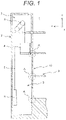
- an elevator device 1 includes a car 4, a counterweight 5, and a main rope 6 in a hoistway 3 of a building 2, and includes a hoist 8 in a machine room 7 of the building 2.
- the main rope 6 having one end connected to the car 4, and the other end connected to the counterweight 5 is hoisted using the hoist 8 so that the car 4 can be moved to an arbitrary floor.
- a landing door 10 to be operated in association with opening and closing operations of a car door of the car 4 is provided on a landing 9 of each floor at a side of the hoistway 3.
- a lower end of the landing door 10 is slidably supported by a landing sill device A to be described later.
- Figure 2 is a front view of the elevator landing sill device as illustrated in Figure 1 , and a periphery of the device.
- Figure 3 is a side sectional view of an enlarged part of the elevator landing sill device as illustrated in Figure 2 .
- the elevator landing sill device A includes a landing sill 12 which is provided along a lower edge 11 of a landing opening, and guides opening and closing operations of the landing door 10.
- a hoistway wall 3a at the landing opening side has multiple fixtures 13, for example, three fixtures (13A, 13B, 13C) arrayed along the longitudinal direction of the landing sill 12.
- a first fastener 14 serves to fix each of the fixtures 13 to the hoistway wall 3a.
- a second fastener 15 serves to fix the landing sill 12 to each of the fixtures 13.
- a third fastener 16 serves to join a wall-side member 13a to be fixed to the hoistway wall 3a using the first fastener 14 and a sill-side member 13b to which the landing sill 12 is fixed using the second fastener 15.
- each of the fixtures 13A, 13B, 13C has the same structure. A detailed explanation will be made with respect to the structure referring to Figure 3 , taking the fixture 13B as an example.
- the wall-side member 13a of the fixture 13B is fixed to the hoistway wall 3a using the first fastener 14 including an anchor bolt 14 and a nut 14b.
- the landing sill 12 is fixed to the sill-side member 13b using the second fastener 15 including a bolt 15a and a nut 15b.
- the wall-side member 13a and the sill-side member 13b are joined using the third fastener 16 including a bolt 16a and a nut 16b (see Figure 2 ) .
- the wall-side member 13a includes a plate-like fixing margin 13aa which is fixed to the hoistway wall 3a using the first fastener 14 while extending along the hoistway wall 3a, and a plate-like joining margin 13ab which is joined with the sill-side member 13b using the third fastener 16 while extending from the fixing margin 13aa parallel to the depth direction (left-right direction as shown in Figure 3 ) of the hoistway 3 and height direction.
- the sill-side member 13b includes a plate-like joining margin 13bb which is joined using the third fastener 16 with the joining margin 13ab of the wall-side member 13a while being overlaid therewith, and a plate-like mounting margin 13ba which extends from the joining margin 13bb parallel to the left-right direction and the depth direction of the hoistway 3, to which the landing sill 12 is fastened using the second fastener 15.
- the fixing margin 13aa of the wall-side member 13a has a bolt insertion part 13ac through which the anchor bolt 14a of the first fastener 14 is inserted.
- the bolt insertion part 13ac is formed into a long hole which is long in the longitudinal direction (y-direction; left-right direction of Figure 2 ) of the landing sill 12. This allows change in the position of the anchor bolt 14a to the fixing margin 13aa in the longitudinal direction of the landing sill 12.
- multiple bolt insertion parts 13ac for example, three bolt insertion parts are arranged at equal intervals in the height direction (z-direction).
- the joining margin 13ab of the wall-side member 13a has a bolt insertion part 13ad through which the bolt 16a of the third fastener 16 is inserted.
- the bolt insertion part 13ad is formed into a long hole which is long in the depth direction (x-direction) of the hoistway 3. This allows change in the relative position between the bolt 16a and the wall-side member 13a in the depth direction of the hoistway 3.
- the joining margin 13bb of the sill-side member 13b has a bolt insertion part 13bc through which the bolt 16a of the third fastener 16 is inserted.
- the bolt insertion part 13bc is formed into a long hole which is long in the height direction (z-direction). This allows change in the relative position between the bolt 16a and the sill-side member 13b in the height direction.
- the wall-side member 13a and the sill-side member 13b are joined by means of the bolt insertion parts 13ad, 13bc so that the position of the sill-side member 13b can be adjusted in the height direction and the depth direction (x-direction; left-right direction of Figure 3 ) of the hoistway 3.
- the partition member 20 is disposed to seal the gap between the landing sill 12 and the hoistway wall 3a of the building 2.
- the partition member 20 is formed into a hinge structure constituted by a center plate 21, a building-side mount part 22, and a sill-side mount part 23.
- the building-side mount part 22 and the sill-side mount part 23 are rotatably attached to the respective sides of the center plate 21.
- the building-side mount part 22 is fixed to the hoistway wall 3a of the building using an anchor bolt (building-side fastener) 24.
- the sill-side mount part 23 is attached to the lower surface of the landing sill 12 using a bolt 25 (sill-side fastener) 25.
- the partition member 20 seals the gap between the landing sill 12 and the hoistway wall 3a of the building 2 to prevent outflow of the mortar 30 poured to make the upper surface of the landing sill 12 flush with the landing floor surface to the inside of the hoistway 3 (see Figure 1 ).
- a floor surface finishing member such as carpet, tile, flooring for forming the floor surface is laid on the upper surface of the mortar 30. Since the heavy load such as a cart other than humans may pass through the landing opening, the thickness or strength of the partition member 20 is determined so that its deformation is kept within an allowable value despite passage of the maximum permissible heavy load conveyable by the elevator.
- a three-way frame 31 is provided at the landing opening.
- the inner width dimension of the three-way frame 31 is substantially the same as the width dimension of the landing opening.
- the width of the partition member 20 is set to be substantially the same as the width dimension of the landing opening.
- Figure 4 is a side view representing a structure of the partition member 20 as illustrated in Figure 3 .
- the partition member 20 includes the center plate 21, the building-side mount part 22 attached to the hoistway wall 3a, and the sill-side mount part 23 attached to the lower surface of the landing sill 12.
- the building-side mount part 22 is rotatably attached to one end of the center plate 21 via a shaft 26, and the sill-side mount part 23 is rotatably attached to the other end of the center plate 21 via a shaft 27.
- the sill-side mount part 23 is fixed to a predetermined position of the lower surface of the landing sill 12 using the bolt 25.
- the sill-side mount part 23 is structured to be in contact with the landing sill over an entire range in contact with the landing sill 12 in the left-right direction (y-direction) so as not to generate the gap.
- the building-side mount part 22 is structured to be in contact with the hoistway wall 3a over an entire range in contact with the hoistway wall 3a in the left-right direction (y-direction) so as not to generate the gap. If the gap is unavoidably generated between the sill-side mount part 23 and the landing sill 12, or between the building-side mount part 22 and the hoistway wall 3a, it is preferable to provide the gap sealing member, for example, plastic sheet.
- a positional relationship between the landing sill 12 and the building 2 is not constant.
- Dimension error of the building 2 makes the dimension between the hoistway wall 3a and the landing sill 12 variable.
- the partition member 20 of the example allows the position of the building-side mount part 22 to be freely changed by means of the two shafts 26, 27 in accordance with the dimension between the hoistway wall 3a and the landing sill 12.
- the anchor bolt 24 is driven into the hoistway wall 3a at a position corresponding to the building-side mount part 22 so that the building-side mount part 22 is vertically moved to be brought into tight contact with the hoistway wall 3a, and the anchor bolt 24 ensures to fix the building-side mount part 22 to the hoistway wall 3a, irrespective of the dimension between the hoistway wall 3a and the landing sill 12.
- the partition member 20 After fixing the partition member 20 to the hoistway wall 3a and the landing sill 12, as illustrated in Figures 3 and 4 , the partition member 20 securely prevents outflow of the mortar 30 in the pouring process to the inside of the hoistway 3.
- Figure 5 is an explanatory view of the structure of the partition member 20, indicating a state before assembling the center plate 21, the building-side mount part 22, and the sill-side mount part 23.
- Figure 6 indicates a state where the center plate 21, the building-side mount part 22, and the sill-side mount part 23 have been assembled.
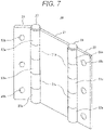
- Figure 7 is a perspective view of the assembled partition member 20.
- FIG. 5 illustrates, multiple tubes 21a (two on each side in the example) through which the shafts 26, 27 penetrate are provided on the respective sides of the center plate 21.
- the building-side mount part 22 and the sill-side mount part 23 include multiple tubes 22a, 23a (three in the example) through which the shafts 26, 27 penetrate, respectively on sides connected to the center plate 21 at positions which are not interfered with the tubes 21a.
- bolt holes 22b, 23b are formed along the longitudinal direction of the partition member 20 (longitudinal direction of the landing sill 12; y-direction).
- the bolt hole 22b accommodates penetration of the anchor bolt 24 as illustrated in Figure 4
- the bolt hole 23b accommodates penetration of the bolt 25 as illustrated in Figure 4 .
- the center plate 21, the building-side mount part 22, and the sill-side mount part 23 are combined as illustrated in Figure 6 .
- the building-side mount part 22 and the sill-side mount part 23 are rotatably assembled with the center plate 21 by means of the shafts 26, 27.
- Figure 7 is a perspective view of the assembled partition member 20.
- the shaft 26 extending from one end to the other end of the partition member 20 penetrates through the tubes 22a of the building-side mount part 22 and the tubes 21a of the center plate 21 so that the building-side mount part 22 is rotatably attached to the center plate 21.
- the shaft 27 extending from one end to the other end of the partition member 20 penetrates through the tubes 23a of the sill-side mount part 23 and the tubes 21a of the center plate 21 so that the sill-side mount part 23 is rotatably attached to the center plate 21.
- Each of the shafts 26, 27 is provided with a stopper for preventing detachment from the partition member 20.
- Figure 8 is an explanatory view of an operation of the partition member 20 in the case of a small gap between the building 2 and the landing sill 12.
- the building-side mount part 22 is moved downward along the hoistway wall 3a to be in tight contact therewith while having the sill-side mount part 23 attached to the landing sill 12.
- the anchor bolt 24 is driven into the hoistway wall 3a at the position corresponding to the bolt hole 22b of the building-side mount part 22.
- the anchor bolt 24 securely fixes the building-side mount part 22 to the hoistway wall 3a in the tight contact state.
- Figure 9 is an explanatory view of an operation of the partition member 20 in the case of a large gap between the building 2 and the landing sill 12.
- the building-side mount part 22 is moved upward to be higher than the position as illustrated in Figure 8 by means of the shafts 26, 27 so that the building-side mount part 22 is brought into tight contact with the hoistway wall 3a.
- the building-side mount part 22 can be securely in tight contact with the hoistway wall 3a.
- the anchor bolt 24 is driven into the hoistway wall 3a at the position corresponding to the bolt hole 22b of the building-side mount part 22.
- the anchor bolt 24 allows the building-side mount part 22 to be securely fixed to the hoistway wall 3a in the tight contact state.
- the partition member 20 of the example allows the position of the building-side mount part 22 to be freely changed by means of the two shafts 26, 27 in accordance with the dimension between the hoistway wall 3a and the landing sill 12.
- the anchor bolt 24 is driven into the building 2 by positioning the building-side mount part 22 to be in tight contact with the hoistway wall 3a so that the partition member 20 can be constantly fixed in tight contact with the hoistway wall 3a and the landing sill 12 irrespective of the dimension therebetween.
- the example ensures to seal the gap between the hoistway wall 3a and the landing sill 12 easily and securely.
- the shaft 26 for connecting the center plate 21 with the building-side mount part 22 of the partition member 20, and the shaft 27 for connecting the center plate 21 with the sill-side mount part 23 are separately formed as individual members.
- the partition member may be configured as illustrated in Figure 10.
- Figure 10 is an explanatory view of another example of the partition member 20, which corresponds to Figure 5 .
- the partition member 20 as illustrated in Figure 10 has multiple tubes 21a on both sides (two for each side) of the center plate 21 for accommodating insertion of the shafts.
- Multiple tubes 22a, 23a are attached to the building-side mount part 22 and the sill-side mount part 23 at positions where those tubes are not interfered with the tubes 21a of the center plate 21.
- Shaft parts 22c, 23c to be inserted into the tubes 21a are fixed to the tubes 22a, 23a, respectively.
- the above-described structure allows the building-side mount part 22 and the sill-side mount part 23 to be rotatably attached to the center plate 21 by inserting the shaft parts 22c, 23c into the tubes 21a of the center plate 21, respectively.
- the shaft part 22c of the tube 22a of the building-side mount part 22 is inserted between the tubes 21a of the center plate 21 and the tubes 21a of the center plate 21, it is necessary to form an axial gap having the length equal to or longer than the length of the shaft part 22c protruding from the tube 22a so that the shaft part 22c can be inserted in the tube 21a.
- the length of the shaft part of the tube 22a or the tube 21a is shorter than that illustrated in Figure 5 , and a gap is formed between the tube 22a and the tube 21a after assembly.
- the partition member 20 may be provided with the gap sealing member.
- the bolt holes 22b, 23b formed in the building-side mount part 22 and the sill-side mount part 23 of the partition member 20 are formed into circular shapes. It is possible to form those bolt holes into long holes which are long in the short-length direction (direction perpendicular to the shafts 26, 27) of the building-side mount part 22 and the sill-side mount part 23 as illustrated in Figure 11.
- Figure 11 is an explanatory view of still another example of the partition member 20, which corresponds to Figure 6 .
- the bolt holes 22b, 23b are formed into long holes which are long in the short-length direction of the building-side mount part 22 and the sill-side mount part 23. Those holes allow the relative position between the anchor bolt 24 and the bolt hole 22b, or between the bolt 25 and the bolt hole 23b to be freely changed in accordance with the dimension between the hoistway wall 3a and the landing sill 12 in spite of variation in the dimension between the hoistway wall 3a and the landing sill 12.
- This makes it possible to bring the building-side mount part 22 into tight contact with the hoistway wall 3a, and the sill-side mount part 23 into tight contact with the landing sill 12. Accordingly, it is possible to fix the building-side mount part 22 to the hoistway wall 3a, and the sill-side mount part 23 to the landing sill 12 each in the tight contact state even after driving the anchor bolt 24 into the building 2.
- the example as illustrated in Figure 11 allows the partition member 20 to be constantly fixed to the hoistway wall 3a and the landing sill 12 in the tight contact state irrespective of the dimension between the hoistway wall 3a and the landing sill 12 even after driving the anchor bolt 24 into the building 2. Accordingly, in the example as illustrated in Figure 11 , it is possible to seal the gap between the hoistway wall 3a and the landing sill 12 further easily and securely.
- the partition member 20 ensures to seal the gap between the hoistway wall 3a and the landing sill 12. It is therefore possible to prevent inflow of the mortar 30 to be poured into the landing floor side of the landing sill 12 for finishing the landing floor to the inside of the hoistway 3 from the gap between the hoistway wall 3a and the landing sill 12.
- the present invention includes various modifications without being limited to the foregoing example.
- the partition member 20 is composed of three members, that is, the center plate 21, the building-side mount part 22, and the sill-side mount part 23.
- the partition member 20 may be composed of four or more members in total including multiple center plates 21. It is possible to use the corrugated plate as the center plate 21 instead of the flat plate.
- the building-side mount part 22 and the sill-side mount part 23 may be structured to have only mount parts while leaving peripheries of the bolt holes 22b, 23b with no limitation to rectangular plates.
- the building-side mount part 22 is fixed to the hoistway wall 3a, and the sill-side mount part 23 is fixed to the lower surface of the landing sill 12. It is also possible to fix the building-side mount part 22 to the upper surface of the building 2, and the sill-side mount part 23 to the side surface of the landing sill 12 with no limitation to those fixing positions.
Landscapes
- Elevator Door Apparatuses (AREA)
Applications Claiming Priority (1)
| Application Number | Priority Date | Filing Date | Title |
|---|---|---|---|
| PCT/JP2019/041129 WO2021075053A1 (ja) | 2019-10-18 | 2019-10-18 | エレベータの乗場敷居装置及びこれを備えたエレベータ装置 |
Publications (3)
| Publication Number | Publication Date |
|---|---|
| EP4046952A1 true EP4046952A1 (de) | 2022-08-24 |
| EP4046952A4 EP4046952A4 (de) | 2023-06-28 |
| EP4046952B1 EP4046952B1 (de) | 2024-07-10 |
Family
ID=75537768
Family Applications (1)
| Application Number | Title | Priority Date | Filing Date |
|---|---|---|---|
| EP19948941.0A Active EP4046952B1 (de) | 2019-10-18 | 2019-10-18 | Aufzugsschachtschwelle und damit ausgestatteter aufzug |
Country Status (5)
| Country | Link |
|---|---|
| US (1) | US11866297B2 (de) |
| EP (1) | EP4046952B1 (de) |
| JP (1) | JP7279181B2 (de) |
| CN (1) | CN114585580B (de) |
| WO (1) | WO2021075053A1 (de) |
Family Cites Families (33)
| Publication number | Priority date | Publication date | Assignee | Title |
|---|---|---|---|---|
| US1051945A (en) * | 1912-10-29 | 1913-02-04 | Bernard Baumann | Safety device for elevators. |
| US2120081A (en) * | 1935-01-02 | 1938-06-07 | Elisha E Alexander | Elevator plate mechanism |
| US2739354A (en) * | 1952-06-12 | 1956-03-27 | Lewis J Pope | Elevator door bridge |
| JPS547649Y2 (de) * | 1973-04-25 | 1979-04-10 | ||
| JPS595024Y2 (ja) * | 1976-02-12 | 1984-02-15 | 三菱電機株式会社 | エレベ−タ乗場の堰板 |
| JPS52149740A (en) * | 1976-06-09 | 1977-12-13 | Hitachi Ltd | Elevator platform control device |
| JPS5950898B2 (ja) | 1977-06-17 | 1984-12-11 | 松下精工株式会社 | ヒ−トポンプ空気調和機の制御回路 |
| JPS5485728U (de) * | 1977-11-30 | 1979-06-18 | ||
| JPS5485728A (en) | 1977-12-20 | 1979-07-07 | Canon Inc | Image forming device |
| JPS5913635B2 (ja) * | 1978-09-05 | 1984-03-30 | 三菱電機株式会社 | エレベ−タ装置 |
| JPS59199981A (ja) * | 1983-04-26 | 1984-11-13 | 株式会社東芝 | エレベ−タ乗場床 |
| US4579503A (en) * | 1983-11-02 | 1986-04-01 | Leyman Manufacturing Corp. | Sideloader elevator platform |
| JP2713013B2 (ja) * | 1992-03-27 | 1998-02-16 | 三菱電機株式会社 | エレベーター用敷居の取付構造 |
| US7788854B2 (en) * | 2002-09-03 | 2010-09-07 | Harold S. Friedman | Elevator entrance door sill pivotable into and out of elevator shaft via hinge connected support and alignment brackets |
| CN1839088B (zh) * | 2003-09-18 | 2010-09-08 | 奥蒂斯电梯公司 | 电梯组件和用于打开电梯门组件的方法 |
| JP2009084029A (ja) | 2007-10-02 | 2009-04-23 | Hitachi Building Systems Co Ltd | エレベータの乗場敷居装置 |
| JP2013107768A (ja) * | 2011-11-24 | 2013-06-06 | Hitachi Ltd | エレベーター装置 |
| CN102602789B (zh) * | 2012-03-27 | 2014-04-16 | 中国矿业大学 | 一种矿用电梯承接平台及承接方法 |
| KR101553220B1 (ko) * | 2014-04-01 | 2015-09-16 | (주)조은엔터프라이즈 | 엘리베이터 도어 씰 구조 |
| EP3031767B1 (de) * | 2014-12-12 | 2021-08-25 | Kone Corporation | Aufzug |
| CN205802735U (zh) * | 2016-04-13 | 2016-12-14 | 苏州捷菱快速电梯有限公司 | 一种用于安装电梯厅门地坎的支架 |
| JP2018008809A (ja) * | 2016-07-15 | 2018-01-18 | 株式会社日立製作所 | 乗りかご及びエレベーター装置 |
| US9932171B1 (en) * | 2016-10-18 | 2018-04-03 | David R. Hall | Bridging apparatus |
| CN206705471U (zh) * | 2017-03-10 | 2017-12-05 | 西子电梯科技有限公司 | 一种可调式层门地坎组件 |
| JP6388418B1 (ja) * | 2017-06-23 | 2018-09-12 | 東芝エレベータ株式会社 | エレベータ装置 |
| JP6768630B2 (ja) * | 2017-12-15 | 2020-10-14 | 株式会社日立ビルシステム | エレベーター装置 |
| CN108002191A (zh) * | 2017-12-29 | 2018-05-08 | 东莞市凯勒帝数控科技有限公司 | 一种电梯用可调节高度的厅门挡泥板 |
| CN207811030U (zh) * | 2018-01-29 | 2018-09-04 | 杭州西奥电梯有限公司 | 一种电梯厅门挡泥板 |
| US11066277B2 (en) * | 2018-04-25 | 2021-07-20 | Otis Elevator Company | Gap-reducing sill assembly for an elevator car |
| US11034549B2 (en) * | 2018-04-25 | 2021-06-15 | Otis Elevator Company | Gap-reducing sill assembly for an elevator car |
| KR102121690B1 (ko) * | 2019-03-25 | 2020-06-10 | 장귀경 | 전단에 연장부재가 결합된 엘리베이터 홀 플로어 커버 |
| JP2021116914A (ja) * | 2020-01-29 | 2021-08-10 | トヨタ自動車株式会社 | 無端金属ベルト |
| JP7610486B2 (ja) * | 2021-08-16 | 2025-01-08 | 株式会社日立製作所 | エレベーターシステム及びエレベーターシステムの制御方法 |
-
2019
- 2019-10-18 EP EP19948941.0A patent/EP4046952B1/de active Active
- 2019-10-18 JP JP2021552080A patent/JP7279181B2/ja active Active
- 2019-10-18 WO PCT/JP2019/041129 patent/WO2021075053A1/ja not_active Ceased
- 2019-10-18 US US17/769,351 patent/US11866297B2/en active Active
- 2019-10-18 CN CN201980101159.3A patent/CN114585580B/zh active Active
Also Published As
| Publication number | Publication date |
|---|---|
| JP7279181B2 (ja) | 2023-05-22 |
| EP4046952B1 (de) | 2024-07-10 |
| WO2021075053A1 (ja) | 2021-04-22 |
| EP4046952A4 (de) | 2023-06-28 |
| CN114585580A (zh) | 2022-06-03 |
| CN114585580B (zh) | 2023-06-09 |
| US11866297B2 (en) | 2024-01-09 |
| US20230339726A1 (en) | 2023-10-26 |
| JPWO2021075053A1 (de) | 2021-04-22 |
Similar Documents
| Publication | Publication Date | Title |
|---|---|---|
| US20150298938A1 (en) | Elevator roller guide | |
| JP5058269B2 (ja) | エレベータかご及びその据付方法 | |
| US20200346898A1 (en) | Elevator landing door assembly and its installation method | |
| EP4046952B1 (de) | Aufzugsschachtschwelle und damit ausgestatteter aufzug | |
| KR102086247B1 (ko) | 엘리베이터 케이지 | |
| JP2015000769A (ja) | エレベータ用かご、及びエレベータのかご据付方法 | |
| JP7406630B2 (ja) | エレベーター装置及びその三方枠の取付構造 | |
| IT201800020236A1 (it) | Impianto elevatore | |
| JP2011144007A (ja) | エレベータのドア装置 | |
| JP7140918B2 (ja) | エレベータの乗場敷居装置 | |
| JP2015157701A (ja) | エレベータの据付装置、及びこの据付装置の組立方法 | |
| JP2013155021A (ja) | エレベータの乗りかご | |
| WO2019138545A1 (ja) | エレベータ及びその改修方法 | |
| KR20040084901A (ko) | 엘리베이터 장치 | |
| JP2001072354A (ja) | エレベータおよびその据付方法 | |
| CN111032559B (zh) | 电梯层站装置 | |
| JP2010126359A (ja) | エレベータのかご | |
| WO2022107300A1 (ja) | ガイドレールの支持構造及びエレベーター | |
| JP7156993B2 (ja) | カウンターウェート及びこれを備えたエレベータ装置 | |
| JP3228821B2 (ja) | エレベータ出入口部材の仮固定装置 | |
| WO2019239595A1 (ja) | エレベータのかご室及びその組立方法 | |
| JPH073142B2 (ja) | エレベ−タの乗場側出入口装置 | |
| KR20250058371A (ko) | 선형조인트 내화구조, 선형조인트용 내화 커버 유닛 및 내화 케이싱 유닛 | |
| JP5146076B2 (ja) | エレベータの乗場装置 | |
| JP4035202B2 (ja) | エレベータ |
Legal Events
| Date | Code | Title | Description |
|---|---|---|---|
| STAA | Information on the status of an ep patent application or granted ep patent |
Free format text: STATUS: THE INTERNATIONAL PUBLICATION HAS BEEN MADE |
|
| PUAI | Public reference made under article 153(3) epc to a published international application that has entered the european phase |
Free format text: ORIGINAL CODE: 0009012 |
|
| STAA | Information on the status of an ep patent application or granted ep patent |
Free format text: STATUS: REQUEST FOR EXAMINATION WAS MADE |
|
| 17P | Request for examination filed |
Effective date: 20220518 |
|
| AK | Designated contracting states |
Kind code of ref document: A1 Designated state(s): AL AT BE BG CH CY CZ DE DK EE ES FI FR GB GR HR HU IE IS IT LI LT LU LV MC MK MT NL NO PL PT RO RS SE SI SK SM TR |
|
| DAV | Request for validation of the european patent (deleted) | ||
| DAX | Request for extension of the european patent (deleted) | ||
| A4 | Supplementary search report drawn up and despatched |
Effective date: 20230525 |
|
| RIC1 | Information provided on ipc code assigned before grant |
Ipc: B66B 13/30 20060101AFI20230519BHEP |
|
| GRAP | Despatch of communication of intention to grant a patent |
Free format text: ORIGINAL CODE: EPIDOSNIGR1 |
|
| STAA | Information on the status of an ep patent application or granted ep patent |
Free format text: STATUS: GRANT OF PATENT IS INTENDED |
|
| INTG | Intention to grant announced |
Effective date: 20240214 |
|
| GRAS | Grant fee paid |
Free format text: ORIGINAL CODE: EPIDOSNIGR3 |
|
| GRAA | (expected) grant |
Free format text: ORIGINAL CODE: 0009210 |
|
| STAA | Information on the status of an ep patent application or granted ep patent |
Free format text: STATUS: THE PATENT HAS BEEN GRANTED |
|
| AK | Designated contracting states |
Kind code of ref document: B1 Designated state(s): AL AT BE BG CH CY CZ DE DK EE ES FI FR GB GR HR HU IE IS IT LI LT LU LV MC MK MT NL NO PL PT RO RS SE SI SK SM TR |
|
| REG | Reference to a national code |
Ref country code: CH Ref legal event code: EP |
|
| REG | Reference to a national code |
Ref country code: DE Ref legal event code: R096 Ref document number: 602019055213 Country of ref document: DE |
|
| REG | Reference to a national code |
Ref country code: LT Ref legal event code: MG9D |
|
| REG | Reference to a national code |
Ref country code: NL Ref legal event code: MP Effective date: 20240710 |
|
| PG25 | Lapsed in a contracting state [announced via postgrant information from national office to epo] |
Ref country code: PT Free format text: LAPSE BECAUSE OF FAILURE TO SUBMIT A TRANSLATION OF THE DESCRIPTION OR TO PAY THE FEE WITHIN THE PRESCRIBED TIME-LIMIT Effective date: 20241111 |
|
| REG | Reference to a national code |
Ref country code: AT Ref legal event code: MK05 Ref document number: 1701912 Country of ref document: AT Kind code of ref document: T Effective date: 20240710 |
|
| PG25 | Lapsed in a contracting state [announced via postgrant information from national office to epo] |
Ref country code: NL Free format text: LAPSE BECAUSE OF FAILURE TO SUBMIT A TRANSLATION OF THE DESCRIPTION OR TO PAY THE FEE WITHIN THE PRESCRIBED TIME-LIMIT Effective date: 20240710 |
|
| PG25 | Lapsed in a contracting state [announced via postgrant information from national office to epo] |
Ref country code: PT Free format text: LAPSE BECAUSE OF FAILURE TO SUBMIT A TRANSLATION OF THE DESCRIPTION OR TO PAY THE FEE WITHIN THE PRESCRIBED TIME-LIMIT Effective date: 20241111 Ref country code: NL Free format text: LAPSE BECAUSE OF FAILURE TO SUBMIT A TRANSLATION OF THE DESCRIPTION OR TO PAY THE FEE WITHIN THE PRESCRIBED TIME-LIMIT Effective date: 20240710 |
|
| PG25 | Lapsed in a contracting state [announced via postgrant information from national office to epo] |
Ref country code: NO Free format text: LAPSE BECAUSE OF FAILURE TO SUBMIT A TRANSLATION OF THE DESCRIPTION OR TO PAY THE FEE WITHIN THE PRESCRIBED TIME-LIMIT Effective date: 20241010 |
|
| PG25 | Lapsed in a contracting state [announced via postgrant information from national office to epo] |
Ref country code: GR Free format text: LAPSE BECAUSE OF FAILURE TO SUBMIT A TRANSLATION OF THE DESCRIPTION OR TO PAY THE FEE WITHIN THE PRESCRIBED TIME-LIMIT Effective date: 20241011 Ref country code: PL Free format text: LAPSE BECAUSE OF FAILURE TO SUBMIT A TRANSLATION OF THE DESCRIPTION OR TO PAY THE FEE WITHIN THE PRESCRIBED TIME-LIMIT Effective date: 20240710 Ref country code: FI Free format text: LAPSE BECAUSE OF FAILURE TO SUBMIT A TRANSLATION OF THE DESCRIPTION OR TO PAY THE FEE WITHIN THE PRESCRIBED TIME-LIMIT Effective date: 20240710 |
|
| PG25 | Lapsed in a contracting state [announced via postgrant information from national office to epo] |
Ref country code: BG Free format text: LAPSE BECAUSE OF FAILURE TO SUBMIT A TRANSLATION OF THE DESCRIPTION OR TO PAY THE FEE WITHIN THE PRESCRIBED TIME-LIMIT Effective date: 20240710 |
|
| PG25 | Lapsed in a contracting state [announced via postgrant information from national office to epo] |
Ref country code: LV Free format text: LAPSE BECAUSE OF FAILURE TO SUBMIT A TRANSLATION OF THE DESCRIPTION OR TO PAY THE FEE WITHIN THE PRESCRIBED TIME-LIMIT Effective date: 20240710 |
|
| PG25 | Lapsed in a contracting state [announced via postgrant information from national office to epo] |
Ref country code: AT Free format text: LAPSE BECAUSE OF FAILURE TO SUBMIT A TRANSLATION OF THE DESCRIPTION OR TO PAY THE FEE WITHIN THE PRESCRIBED TIME-LIMIT Effective date: 20240710 Ref country code: IS Free format text: LAPSE BECAUSE OF FAILURE TO SUBMIT A TRANSLATION OF THE DESCRIPTION OR TO PAY THE FEE WITHIN THE PRESCRIBED TIME-LIMIT Effective date: 20241110 |
|
| PG25 | Lapsed in a contracting state [announced via postgrant information from national office to epo] |
Ref country code: HR Free format text: LAPSE BECAUSE OF FAILURE TO SUBMIT A TRANSLATION OF THE DESCRIPTION OR TO PAY THE FEE WITHIN THE PRESCRIBED TIME-LIMIT Effective date: 20240710 |
|
| PG25 | Lapsed in a contracting state [announced via postgrant information from national office to epo] |
Ref country code: ES Free format text: LAPSE BECAUSE OF FAILURE TO SUBMIT A TRANSLATION OF THE DESCRIPTION OR TO PAY THE FEE WITHIN THE PRESCRIBED TIME-LIMIT Effective date: 20240710 Ref country code: RS Free format text: LAPSE BECAUSE OF FAILURE TO SUBMIT A TRANSLATION OF THE DESCRIPTION OR TO PAY THE FEE WITHIN THE PRESCRIBED TIME-LIMIT Effective date: 20241010 |
|
| PG25 | Lapsed in a contracting state [announced via postgrant information from national office to epo] |
Ref country code: RS Free format text: LAPSE BECAUSE OF FAILURE TO SUBMIT A TRANSLATION OF THE DESCRIPTION OR TO PAY THE FEE WITHIN THE PRESCRIBED TIME-LIMIT Effective date: 20241010 Ref country code: PL Free format text: LAPSE BECAUSE OF FAILURE TO SUBMIT A TRANSLATION OF THE DESCRIPTION OR TO PAY THE FEE WITHIN THE PRESCRIBED TIME-LIMIT Effective date: 20240710 Ref country code: NO Free format text: LAPSE BECAUSE OF FAILURE TO SUBMIT A TRANSLATION OF THE DESCRIPTION OR TO PAY THE FEE WITHIN THE PRESCRIBED TIME-LIMIT Effective date: 20241010 Ref country code: LV Free format text: LAPSE BECAUSE OF FAILURE TO SUBMIT A TRANSLATION OF THE DESCRIPTION OR TO PAY THE FEE WITHIN THE PRESCRIBED TIME-LIMIT Effective date: 20240710 Ref country code: IS Free format text: LAPSE BECAUSE OF FAILURE TO SUBMIT A TRANSLATION OF THE DESCRIPTION OR TO PAY THE FEE WITHIN THE PRESCRIBED TIME-LIMIT Effective date: 20241110 Ref country code: HR Free format text: LAPSE BECAUSE OF FAILURE TO SUBMIT A TRANSLATION OF THE DESCRIPTION OR TO PAY THE FEE WITHIN THE PRESCRIBED TIME-LIMIT Effective date: 20240710 Ref country code: GR Free format text: LAPSE BECAUSE OF FAILURE TO SUBMIT A TRANSLATION OF THE DESCRIPTION OR TO PAY THE FEE WITHIN THE PRESCRIBED TIME-LIMIT Effective date: 20241011 Ref country code: FI Free format text: LAPSE BECAUSE OF FAILURE TO SUBMIT A TRANSLATION OF THE DESCRIPTION OR TO PAY THE FEE WITHIN THE PRESCRIBED TIME-LIMIT Effective date: 20240710 Ref country code: ES Free format text: LAPSE BECAUSE OF FAILURE TO SUBMIT A TRANSLATION OF THE DESCRIPTION OR TO PAY THE FEE WITHIN THE PRESCRIBED TIME-LIMIT Effective date: 20240710 Ref country code: BG Free format text: LAPSE BECAUSE OF FAILURE TO SUBMIT A TRANSLATION OF THE DESCRIPTION OR TO PAY THE FEE WITHIN THE PRESCRIBED TIME-LIMIT Effective date: 20240710 Ref country code: AT Free format text: LAPSE BECAUSE OF FAILURE TO SUBMIT A TRANSLATION OF THE DESCRIPTION OR TO PAY THE FEE WITHIN THE PRESCRIBED TIME-LIMIT Effective date: 20240710 |
|
| REG | Reference to a national code |
Ref country code: DE Ref legal event code: R097 Ref document number: 602019055213 Country of ref document: DE |
|
| PG25 | Lapsed in a contracting state [announced via postgrant information from national office to epo] |
Ref country code: DK Free format text: LAPSE BECAUSE OF FAILURE TO SUBMIT A TRANSLATION OF THE DESCRIPTION OR TO PAY THE FEE WITHIN THE PRESCRIBED TIME-LIMIT Effective date: 20240710 Ref country code: SM Free format text: LAPSE BECAUSE OF FAILURE TO SUBMIT A TRANSLATION OF THE DESCRIPTION OR TO PAY THE FEE WITHIN THE PRESCRIBED TIME-LIMIT Effective date: 20240710 Ref country code: RO Free format text: LAPSE BECAUSE OF FAILURE TO SUBMIT A TRANSLATION OF THE DESCRIPTION OR TO PAY THE FEE WITHIN THE PRESCRIBED TIME-LIMIT Effective date: 20240710 |
|
| PG25 | Lapsed in a contracting state [announced via postgrant information from national office to epo] |
Ref country code: EE Free format text: LAPSE BECAUSE OF FAILURE TO SUBMIT A TRANSLATION OF THE DESCRIPTION OR TO PAY THE FEE WITHIN THE PRESCRIBED TIME-LIMIT Effective date: 20240710 |
|
| PG25 | Lapsed in a contracting state [announced via postgrant information from national office to epo] |
Ref country code: CZ Free format text: LAPSE BECAUSE OF FAILURE TO SUBMIT A TRANSLATION OF THE DESCRIPTION OR TO PAY THE FEE WITHIN THE PRESCRIBED TIME-LIMIT Effective date: 20240710 |
|
| PG25 | Lapsed in a contracting state [announced via postgrant information from national office to epo] |
Ref country code: SK Free format text: LAPSE BECAUSE OF FAILURE TO SUBMIT A TRANSLATION OF THE DESCRIPTION OR TO PAY THE FEE WITHIN THE PRESCRIBED TIME-LIMIT Effective date: 20240710 Ref country code: IT Free format text: LAPSE BECAUSE OF FAILURE TO SUBMIT A TRANSLATION OF THE DESCRIPTION OR TO PAY THE FEE WITHIN THE PRESCRIBED TIME-LIMIT Effective date: 20240710 |
|
| PLBE | No opposition filed within time limit |
Free format text: ORIGINAL CODE: 0009261 |
|
| STAA | Information on the status of an ep patent application or granted ep patent |
Free format text: STATUS: NO OPPOSITION FILED WITHIN TIME LIMIT |
|
| REG | Reference to a national code |
Ref country code: CH Ref legal event code: PL |
|
| 26N | No opposition filed |
Effective date: 20250411 |
|
| GBPC | Gb: european patent ceased through non-payment of renewal fee |
Effective date: 20241018 |
|
| PG25 | Lapsed in a contracting state [announced via postgrant information from national office to epo] |
Ref country code: MC Free format text: LAPSE BECAUSE OF FAILURE TO SUBMIT A TRANSLATION OF THE DESCRIPTION OR TO PAY THE FEE WITHIN THE PRESCRIBED TIME-LIMIT Effective date: 20240710 |
|
| PG25 | Lapsed in a contracting state [announced via postgrant information from national office to epo] |
Ref country code: GB Free format text: LAPSE BECAUSE OF NON-PAYMENT OF DUE FEES Effective date: 20241018 |
|
| PG25 | Lapsed in a contracting state [announced via postgrant information from national office to epo] |
Ref country code: BE Free format text: LAPSE BECAUSE OF NON-PAYMENT OF DUE FEES Effective date: 20241031 Ref country code: LU Free format text: LAPSE BECAUSE OF NON-PAYMENT OF DUE FEES Effective date: 20241018 |
|
| PG25 | Lapsed in a contracting state [announced via postgrant information from national office to epo] |
Ref country code: CH Free format text: LAPSE BECAUSE OF NON-PAYMENT OF DUE FEES Effective date: 20241031 |
|
| REG | Reference to a national code |
Ref country code: BE Ref legal event code: MM Effective date: 20241031 |
|
| PG25 | Lapsed in a contracting state [announced via postgrant information from national office to epo] |
Ref country code: SE Free format text: LAPSE BECAUSE OF FAILURE TO SUBMIT A TRANSLATION OF THE DESCRIPTION OR TO PAY THE FEE WITHIN THE PRESCRIBED TIME-LIMIT Effective date: 20240710 |
|
| PG25 | Lapsed in a contracting state [announced via postgrant information from national office to epo] |
Ref country code: IE Free format text: LAPSE BECAUSE OF NON-PAYMENT OF DUE FEES Effective date: 20241018 |
|
| PGFP | Annual fee paid to national office [announced via postgrant information from national office to epo] |
Ref country code: DE Payment date: 20251031 Year of fee payment: 7 |
|
| PGFP | Annual fee paid to national office [announced via postgrant information from national office to epo] |
Ref country code: FR Payment date: 20251024 Year of fee payment: 7 |
|
| PG25 | Lapsed in a contracting state [announced via postgrant information from national office to epo] |
Ref country code: CY Free format text: LAPSE BECAUSE OF FAILURE TO SUBMIT A TRANSLATION OF THE DESCRIPTION OR TO PAY THE FEE WITHIN THE PRESCRIBED TIME-LIMIT; INVALID AB INITIO Effective date: 20191018 |
|
| PG25 | Lapsed in a contracting state [announced via postgrant information from national office to epo] |
Ref country code: HU Free format text: LAPSE BECAUSE OF FAILURE TO SUBMIT A TRANSLATION OF THE DESCRIPTION OR TO PAY THE FEE WITHIN THE PRESCRIBED TIME-LIMIT; INVALID AB INITIO Effective date: 20191018 |