EP4046952B1 - Aufzugsschachtschwelle und damit ausgestatteter aufzug - Google Patents
Aufzugsschachtschwelle und damit ausgestatteter aufzug Download PDFInfo
- Publication number
- EP4046952B1 EP4046952B1 EP19948941.0A EP19948941A EP4046952B1 EP 4046952 B1 EP4046952 B1 EP 4046952B1 EP 19948941 A EP19948941 A EP 19948941A EP 4046952 B1 EP4046952 B1 EP 4046952B1
- Authority
- EP
- European Patent Office
- Prior art keywords
- sill
- building
- mount part
- side mount
- landing
- Prior art date
- Legal status (The legal status is an assumption and is not a legal conclusion. Google has not performed a legal analysis and makes no representation as to the accuracy of the status listed.)
- Active
Links
Images


Classifications
-
- B—PERFORMING OPERATIONS; TRANSPORTING
- B66—HOISTING; LIFTING; HAULING
- B66B—ELEVATORS; ESCALATORS OR MOVING WALKWAYS
- B66B13/00—Doors, gates, or other apparatus controlling access to, or exit from, cages or lift well landings
- B66B13/30—Constructional features of doors or gates
- B66B13/301—Details of door sills
Definitions
- the elevator landing sill device includes a landing sill provided along a lower edge of a landing opening for guiding opening and closing operations of a landing door, a fixture that is fixed to a hoistway wall at the landing opening side using a first fastener including bolts, to which the landing sill is fixed using a second fastener including bolts, and a partition member that is held between the fixture and the landing sill, and fastened to the fixture jointly with the landing sill using the second fastener.
- the partition member seals a gap between the hoistway wall and the landing sill to prevent inflow of mortar used for finishing the landing floor to the inside of the hoistway from the gap.
- the fixture includes a wall-side member that is fixed to the hoistway wall using the first fastener, and a sill-side member to which the landing sill is fixed using the second fastener.
- the wall-side member and the sill-side member are joined to allow positional adjustment of the sill-side member in a height direction and a depth direction of the hoistway.
- the partition member includes a first held plate to be held between the hoistway wall and the wall-side member, and a second held plate to be held between the sill-side member and the landing sill.
- the first held plate has a first relief part formed to accommodate insertion of the bolt as the first fastener, and to allow change in the position of the first held plate to the bolt in the height direction.
- the second held plate has a second relief part formed to accommodate insertion of the bolt as the second fastener, and to allow change in the position of the bolt to the second held plate in the depth direction of the hoistway.
- the partition member includes a center plate, a building-side mount part attached to one end of the center plate, a sill-side mount part attached to the other end of the center plate, a building-side rotating part for rotatably fixing the center plate and the building-side mount part, and a sill-side rotating part for rotatably fixing the center plate and the sill-side mount part.
- the device further includes a building-side fastener for fixing the building-side mount part to the building, and a sill-side fastener for fixing the sill-side mount part to the landing sill.
- an elevator device 1 includes a car 4, a counterweight 5, and a main rope 6 in a hoistway 3 of a building 2, and includes a hoist 8 in a machine room 7 of the building 2.
- the main rope 6 having one end connected to the car 4, and the other end connected to the counterweight 5 is hoisted using the hoist 8 so that the car 4 can be moved to an arbitrary floor.
- a landing door 10 to be operated in association with opening and closing operations of a car door of the car 4 is provided on a landing 9 of each floor at a side of the hoistway 3.
- a lower end of the landing door 10 is slidably supported by a landing sill device A to be described later.
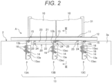
- the elevator landing sill device A includes a landing sill 12 which is provided along a lower edge 11 of a landing opening, and guides opening and closing operations of the landing door 10.
- a hoistway wall 3a at the landing opening side has multiple fixtures 13, for example, three fixtures (13A, 13B, 13C) arrayed along the longitudinal direction of the landing sill 12.
- a first fastener 14 serves to fix each of the fixtures 13 to the hoistway wall 3a.
- a second fastener 15 serves to fix the landing sill 12 to each of the fixtures 13.
- a third fastener 16 serves to join a wall-side member 13a to be fixed to the hoistway wall 3a using the first fastener 14 and a sill-side member 13b to which the landing sill 12 is fixed using the second fastener 15.
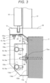
- the wall-side member 13a includes a plate-like fixing margin 13aa which is fixed to the hoistway wall 3a using the first fastener 14 while extending along the hoistway wall 3a, and a plate-like joining margin 13ab which is joined with the sill-side member 13b using the third fastener 16 while extending from the fixing margin 13aa parallel to the depth direction (left-right direction as shown in Figure 3 ) of the hoistway 3 and height direction.
- the joining margin 13ab of the wall-side member 13a has a bolt insertion part 13ad through which the bolt 16a of the third fastener 16 is inserted.
- the bolt insertion part 13ad is formed into a long hole which is long in the depth direction (x-direction) of the hoistway 3. This allows change in the relative position between the bolt 16a and the wall-side member 13a in the depth direction of the hoistway 3.
- the partition member 20 is disposed to seal the gap between the landing sill 12 and the hoistway wall 3a of the building 2.
- the partition member 20 is formed into a hinge structure constituted by a center plate 21, a building-side mount part 22, and a sill-side mount part 23.
- the building-side mount part 22 and the sill-side mount part 23 are rotatably attached to the respective sides of the center plate 21.
- the building-side mount part 22 is fixed to the hoistway wall 3a of the building using an anchor bolt (building-side fastener) 24.
- the sill-side mount part 23 is attached to the lower surface of the landing sill 12 using a bolt 25 (sill-side fastener) 25.
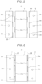
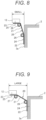
- Figure 8 is an explanatory view of an operation of the partition member 20 in the case of a small gap between the building 2 and the landing sill 12.
- the building-side mount part 22 is moved downward along the hoistway wall 3a to be in tight contact therewith while having the sill-side mount part 23 attached to the landing sill 12.
- the anchor bolt 24 is driven into the hoistway wall 3a at the position corresponding to the bolt hole 22b of the building-side mount part 22.
- the anchor bolt 24 securely fixes the building-side mount part 22 to the hoistway wall 3a in the tight contact state.
- the partition member 20 of the example allows the position of the building-side mount part 22 to be freely changed by means of the two shafts 26, 27 in accordance with the dimension between the hoistway wall 3a and the landing sill 12.
- the anchor bolt 24 is driven into the building 2 by positioning the building-side mount part 22 to be in tight contact with the hoistway wall 3a so that the partition member 20 can be constantly fixed in tight contact with the hoistway wall 3a and the landing sill 12 irrespective of the dimension therebetween.
- the example ensures to seal the gap between the hoistway wall 3a and the landing sill 12 easily and securely.
- the shaft 26 for connecting the center plate 21 with the building-side mount part 22 of the partition member 20, and the shaft 27 for connecting the center plate 21 with the sill-side mount part 23 are separately formed as individual members.
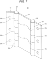
- the partition member may be configured as illustrated in Figure 10.
- Figure 10 is an explanatory view of another example of the partition member 20, which corresponds to Figure 5 .
- the partition member 20 as illustrated in Figure 10 has multiple tubes 21a on both sides (two for each side) of the center plate 21 for accommodating insertion of the shafts.
- Multiple tubes 22a, 23a are attached to the building-side mount part 22 and the sill-side mount part 23 at positions where those tubes are not interfered with the tubes 21a of the center plate 21.
- Shaft parts 22c, 23c to be inserted into the tubes 21a are fixed to the tubes 22a, 23a, respectively.
- the above-described structure allows the building-side mount part 22 and the sill-side mount part 23 to be rotatably attached to the center plate 21 by inserting the shaft parts 22c, 23c into the tubes 21a of the center plate 21, respectively.
- the partition member 20 ensures to seal the gap between the hoistway wall 3a and the landing sill 12. It is therefore possible to prevent inflow of the mortar 30 to be poured into the landing floor side of the landing sill 12 for finishing the landing floor to the inside of the hoistway 3 from the gap between the hoistway wall 3a and the landing sill 12.
Landscapes
- Elevator Door Apparatuses (AREA)
Claims (11)
- Aufzugsschwellenvorrichtung (A) mit einem in einem Gebäude vorgesehenen Schacht (3) zum Auf- und Abbewegen einer Kabine (4), einer an einer Schachtseite des Gebäudes ausgebildeten Landeöffnung, einer entlang einer Unterkante der Landeöffnung angeordneten Landeschwelle (12) zum Führen von Öffnungs- und Schließvorgängen einer Landetür (10) und einer an einer Schachtwand (3a) des Gebäudes befestigten Halterung mit einem oberen Teil, an dem die Landeschwelle (12) befestigt ist, wobei die Aufzugsschwellenvorrichtung (A) ein Trennelement (20) zum Abdichten eines Spalts zwischen der Landeschwelle (12) und der Schachtwand (3a) aufweist,dadurch gekennzeichnet, dass das Trennelement (20) eine Mittelplatte (21), einen an einem Ende der Mittelplatte (21) befestigten gebäudeseitigen Montageteil (22), einen am anderen Ende der Mittelplatte (21) befestigten schwellenseitigen Montageteil (23), einen gebäudeseitigen Drehteil (26) zum drehbaren Befestigen der Mittelplatte (21) und des gebäudeseitigen Montageteils (22) und einen schwellenseitigen Drehteil (27) zum drehbaren Befestigen der Mittelplatte (21) und des schwellenseitigen Montageteils (23) aufweist; undein gebäudeseitiges Befestigungselement (24) zum Befestigen des gebäudeseitigen Montageteils (22) am Gebäude und ein schwellenseitiges Befestigungselement (25) zum Befestigen des schwellenseitigen Montageteils (23) an der Landeschwelle (12) vorgesehen sind.
- Aufzugsschwellenvorrichtung (A) nach Anspruch 1,
wobei der gebäudeseitige Montageteil (22) des Trennelements (20) unter Verwendung des gebäudeseitigen Befestigungselements an der Schachtwand (3a) des Gebäudes befestigt ist und der schwellenseitige Montageteil (23) unter Verwendung des schwellenseitigen Befestigungselements an einer Unterseite der Landeschwelle (12) befestigt ist. - Aufzugsschwellenvorrichtung (A) nach Anspruch 1,
wobei die Dicke oder Festigkeit des Trennelements (20) so bestimmt ist, dass die Verformung des Trennelements (20) trotz des Durchgangs einer maximal zulässigen schweren Last, die vom Aufzug befördert werden kann, innerhalb eines zulässigen Werts gehalten wird. - Aufzugsschwellenvorrichtung (A) nach Anspruch 2,
wobei der gebäudeseitige Montageteil (22) des Trennelements (20) über einen Schaft drehbar an dem einen Ende der Mittelplatte (21) befestigt ist und der schwellenseitige Montageteil (23) über einen Schaft drehbar an dem anderen Ende der Mittelplatte (21) befestigt ist. - Aufzugsschwellenvorrichtung (A) nach Anspruch 1,
wobei der schwellenseitige Montageteil (23) des Trennelements (20) so konfiguriert ist, dass er über einen gesamten Bereich in einer Links-Rechts-Richtung mit der Landeschwelle (12) in Kontakt steht, und der gebäudeseitige Montageteil (22) so konfiguriert ist, dass er über einen gesamten Bereich in der Links-Rechts-Richtung mit der Schachtwand (3a) in Kontakt steht. - Aufzugsschwellenvorrichtung (A) nach Anspruch 1, mit einem Element zum Abdichten eines zwischen dem schwellenseitigen Montageteil (23) des Trennelements (20) und der Landeschwelle (12) erzeugten Spalts oder eines zwischen dem gebäudeseitigen Montageteil (22) und der Schachtwand (3a) erzeugten Spalts.
- Aufzugsschwellenvorrichtung (A) nach Anspruch 4, wobei mehrere Rohre (21a), durch die die Schäfte (26, 27) hindurchgehen, auf beiden Seiten der Mittelplatte (21) des Trennelements (20) vorgesehen sind und der gebäudeseitige Montageteil (22) und der schwellenseitige Montageteil (23) mehrere Rohre (22a, 23a) aufweisen, durch die die Schäfte (26, 27) auf Seiten hindurchgehen, die mit der Mittelplatte (21) verbunden sind, jeweils an einer Position, die nicht mit den Rohren (21a) der Mittelplatte (21) interferiert.
- Aufzugsschwellenvorrichtung (A) nach Anspruch 7,wobei das gebäudeseitige Befestigungselement (24) ein Ankerbolzen (24) ist und das schwellenseitige Befestigungselement (25) ein Bolzen (25) ist; undder gebäudeseitige Montageteil (22) des Trennelements (20) mehrere Bolzenlöcher (22b) aufweist, die das Einführen des Ankerbolzens (24) in einer Längsrichtung ermöglichen, und der schwellenseitige Montageteil (23) mehrere Bolzenlöcher (23b) aufweist, die das Einführen des Bolzens (25) in der Längsrichtung ermöglichen.
- Aufzugsschwellenvorrichtung (A) nach Anspruch 7,
wobei das Trennelement (20) mehrere Rohre (21a) aufweist, die auf beiden Seiten der Mittelplatte (21) vorgesehen sind, durch die die Schäfte (26, 27) eingeführt sind, der gebäudeseitige Montageteil (22) und der schwellenseitige Montageteil (23) jeweils mit mehreren Rohren (22a, 23a) an Positionen versehen sind, die nicht mit den Rohren (21a) der Mittelplatte (21) interferieren, Schaftteile (22c, 23c), die in die Rohre (21a) der Mittelplatte (21) einzuführen sind, an den Rohren (22a, 23a) des gebäudeseitigen Montageteils (22) und des schwellenseitigen Montageteils (23) befestigt sind und der gebäudeseitige Montageteil (22) und der schwellenseitige Montageteil (23) durch Einführen der Schaftteile (22c, 23c) in die Rohre (21a) der Mittelplatte (21) drehbar an der Mittelplatte (21) befestigt sind. - Aufzugsschwellenvorrichtung (A) nach Anspruch 8,
wobei die Bolzenlöcher (22b), die in dem gebäudeseitigen Montageteil (22) und dem schwellenseitigen Montageteil (23) des Trennelements (20) ausgebildet sind, zu langen Löchern ausgebildet sind, von denen jedes in einer Richtung der kurzen Länge des gebäudeseitigen Montageteils (22) oder des schwellenseitigen Montageteils (23) lang ist. - Aufzugsvorrichtung (1) mit einer Kabine (4), die sich in einem Schacht (3) eines Gebäudes auf- und abbewegt, einem Aufzug (8) zum Auf- und Abbewegen der Kabine (4) und einer Aufzugsschwellenvorrichtung (A), die entlang einer Unterkante einer Landeöffnung an einer Schachtseite des Gebäudes zum Führen von Öffnungs- und Schließvorgängen einer Landetür (10) vorgesehen ist,
wobei die Aufzugsschwellenvorrichtung (A) die Aufzugsschwellenvorrichtung (A) nach einem der Ansprüche 1 bis 10 ist.
Applications Claiming Priority (1)
| Application Number | Priority Date | Filing Date | Title |
|---|---|---|---|
| PCT/JP2019/041129 WO2021075053A1 (ja) | 2019-10-18 | 2019-10-18 | エレベータの乗場敷居装置及びこれを備えたエレベータ装置 |
Publications (3)
| Publication Number | Publication Date |
|---|---|
| EP4046952A1 EP4046952A1 (de) | 2022-08-24 |
| EP4046952A4 EP4046952A4 (de) | 2023-06-28 |
| EP4046952B1 true EP4046952B1 (de) | 2024-07-10 |
Family
ID=75537768
Family Applications (1)
| Application Number | Title | Priority Date | Filing Date |
|---|---|---|---|
| EP19948941.0A Active EP4046952B1 (de) | 2019-10-18 | 2019-10-18 | Aufzugsschachtschwelle und damit ausgestatteter aufzug |
Country Status (5)
| Country | Link |
|---|---|
| US (1) | US11866297B2 (de) |
| EP (1) | EP4046952B1 (de) |
| JP (1) | JP7279181B2 (de) |
| CN (1) | CN114585580B (de) |
| WO (1) | WO2021075053A1 (de) |
Family Cites Families (33)
| Publication number | Priority date | Publication date | Assignee | Title |
|---|---|---|---|---|
| US1051945A (en) * | 1912-10-29 | 1913-02-04 | Bernard Baumann | Safety device for elevators. |
| US2120081A (en) * | 1935-01-02 | 1938-06-07 | Elisha E Alexander | Elevator plate mechanism |
| US2739354A (en) * | 1952-06-12 | 1956-03-27 | Lewis J Pope | Elevator door bridge |
| JPS547649Y2 (de) * | 1973-04-25 | 1979-04-10 | ||
| JPS595024Y2 (ja) * | 1976-02-12 | 1984-02-15 | 三菱電機株式会社 | エレベ−タ乗場の堰板 |
| JPS52149740A (en) * | 1976-06-09 | 1977-12-13 | Hitachi Ltd | Elevator platform control device |
| JPS5950898B2 (ja) | 1977-06-17 | 1984-12-11 | 松下精工株式会社 | ヒ−トポンプ空気調和機の制御回路 |
| JPS5485728U (de) * | 1977-11-30 | 1979-06-18 | ||
| JPS5485728A (en) | 1977-12-20 | 1979-07-07 | Canon Inc | Image forming device |
| JPS5913635B2 (ja) * | 1978-09-05 | 1984-03-30 | 三菱電機株式会社 | エレベ−タ装置 |
| JPS59199981A (ja) * | 1983-04-26 | 1984-11-13 | 株式会社東芝 | エレベ−タ乗場床 |
| US4579503A (en) * | 1983-11-02 | 1986-04-01 | Leyman Manufacturing Corp. | Sideloader elevator platform |
| JP2713013B2 (ja) * | 1992-03-27 | 1998-02-16 | 三菱電機株式会社 | エレベーター用敷居の取付構造 |
| US7788854B2 (en) * | 2002-09-03 | 2010-09-07 | Harold S. Friedman | Elevator entrance door sill pivotable into and out of elevator shaft via hinge connected support and alignment brackets |
| CN1839088B (zh) * | 2003-09-18 | 2010-09-08 | 奥蒂斯电梯公司 | 电梯组件和用于打开电梯门组件的方法 |
| JP2009084029A (ja) | 2007-10-02 | 2009-04-23 | Hitachi Building Systems Co Ltd | エレベータの乗場敷居装置 |
| JP2013107768A (ja) * | 2011-11-24 | 2013-06-06 | Hitachi Ltd | エレベーター装置 |
| CN102602789B (zh) * | 2012-03-27 | 2014-04-16 | 中国矿业大学 | 一种矿用电梯承接平台及承接方法 |
| KR101553220B1 (ko) * | 2014-04-01 | 2015-09-16 | (주)조은엔터프라이즈 | 엘리베이터 도어 씰 구조 |
| EP3031767B1 (de) * | 2014-12-12 | 2021-08-25 | Kone Corporation | Aufzug |
| CN205802735U (zh) * | 2016-04-13 | 2016-12-14 | 苏州捷菱快速电梯有限公司 | 一种用于安装电梯厅门地坎的支架 |
| JP2018008809A (ja) * | 2016-07-15 | 2018-01-18 | 株式会社日立製作所 | 乗りかご及びエレベーター装置 |
| US9932171B1 (en) * | 2016-10-18 | 2018-04-03 | David R. Hall | Bridging apparatus |
| CN206705471U (zh) * | 2017-03-10 | 2017-12-05 | 西子电梯科技有限公司 | 一种可调式层门地坎组件 |
| JP6388418B1 (ja) * | 2017-06-23 | 2018-09-12 | 東芝エレベータ株式会社 | エレベータ装置 |
| JP6768630B2 (ja) * | 2017-12-15 | 2020-10-14 | 株式会社日立ビルシステム | エレベーター装置 |
| CN108002191A (zh) * | 2017-12-29 | 2018-05-08 | 东莞市凯勒帝数控科技有限公司 | 一种电梯用可调节高度的厅门挡泥板 |
| CN207811030U (zh) * | 2018-01-29 | 2018-09-04 | 杭州西奥电梯有限公司 | 一种电梯厅门挡泥板 |
| US11066277B2 (en) * | 2018-04-25 | 2021-07-20 | Otis Elevator Company | Gap-reducing sill assembly for an elevator car |
| US11034549B2 (en) * | 2018-04-25 | 2021-06-15 | Otis Elevator Company | Gap-reducing sill assembly for an elevator car |
| KR102121690B1 (ko) * | 2019-03-25 | 2020-06-10 | 장귀경 | 전단에 연장부재가 결합된 엘리베이터 홀 플로어 커버 |
| JP2021116914A (ja) * | 2020-01-29 | 2021-08-10 | トヨタ自動車株式会社 | 無端金属ベルト |
| JP7610486B2 (ja) * | 2021-08-16 | 2025-01-08 | 株式会社日立製作所 | エレベーターシステム及びエレベーターシステムの制御方法 |
-
2019
- 2019-10-18 EP EP19948941.0A patent/EP4046952B1/de active Active
- 2019-10-18 JP JP2021552080A patent/JP7279181B2/ja active Active
- 2019-10-18 WO PCT/JP2019/041129 patent/WO2021075053A1/ja not_active Ceased
- 2019-10-18 US US17/769,351 patent/US11866297B2/en active Active
- 2019-10-18 CN CN201980101159.3A patent/CN114585580B/zh active Active
Also Published As
| Publication number | Publication date |
|---|---|
| JP7279181B2 (ja) | 2023-05-22 |
| WO2021075053A1 (ja) | 2021-04-22 |
| EP4046952A4 (de) | 2023-06-28 |
| CN114585580A (zh) | 2022-06-03 |
| CN114585580B (zh) | 2023-06-09 |
| US11866297B2 (en) | 2024-01-09 |
| US20230339726A1 (en) | 2023-10-26 |
| EP4046952A1 (de) | 2022-08-24 |
| JPWO2021075053A1 (de) | 2021-04-22 |
Similar Documents
| Publication | Publication Date | Title |
|---|---|---|
| US20150298938A1 (en) | Elevator roller guide | |
| JP5058269B2 (ja) | エレベータかご及びその据付方法 | |
| US20200346898A1 (en) | Elevator landing door assembly and its installation method | |
| EP4046952B1 (de) | Aufzugsschachtschwelle und damit ausgestatteter aufzug | |
| KR102086247B1 (ko) | 엘리베이터 케이지 | |
| JP2015000769A (ja) | エレベータ用かご、及びエレベータのかご据付方法 | |
| WO2016125229A1 (ja) | エレベータのフェッシャープレート、及びフェッシャープレートの組立方法 | |
| IT201800020236A1 (it) | Impianto elevatore | |
| JP7406630B2 (ja) | エレベーター装置及びその三方枠の取付構造 | |
| JP2011144007A (ja) | エレベータのドア装置 | |
| JP7149835B2 (ja) | 乗りかご及びエレベーター | |
| JP7140918B2 (ja) | エレベータの乗場敷居装置 | |
| KR100964722B1 (ko) | 엘리베이터의 권상기 설치구조와 케이지 조립체 | |
| JP2015157701A (ja) | エレベータの据付装置、及びこの据付装置の組立方法 | |
| WO2019138545A1 (ja) | エレベータ及びその改修方法 | |
| JP2013155021A (ja) | エレベータの乗りかご | |
| JP2001072354A (ja) | エレベータおよびその据付方法 | |
| KR20040084901A (ko) | 엘리베이터 장치 | |
| JP2010126359A (ja) | エレベータのかご | |
| WO2022107300A1 (ja) | ガイドレールの支持構造及びエレベーター | |
| JP3228821B2 (ja) | エレベータ出入口部材の仮固定装置 | |
| CN111032559B (zh) | 电梯层站装置 | |
| WO2019239595A1 (ja) | エレベータのかご室及びその組立方法 | |
| JPH073142B2 (ja) | エレベ−タの乗場側出入口装置 | |
| JP4035202B2 (ja) | エレベータ |
Legal Events
| Date | Code | Title | Description |
|---|---|---|---|
| STAA | Information on the status of an ep patent application or granted ep patent |
Free format text: STATUS: THE INTERNATIONAL PUBLICATION HAS BEEN MADE |
|
| PUAI | Public reference made under article 153(3) epc to a published international application that has entered the european phase |
Free format text: ORIGINAL CODE: 0009012 |
|
| STAA | Information on the status of an ep patent application or granted ep patent |
Free format text: STATUS: REQUEST FOR EXAMINATION WAS MADE |
|
| 17P | Request for examination filed |
Effective date: 20220518 |
|
| AK | Designated contracting states |
Kind code of ref document: A1 Designated state(s): AL AT BE BG CH CY CZ DE DK EE ES FI FR GB GR HR HU IE IS IT LI LT LU LV MC MK MT NL NO PL PT RO RS SE SI SK SM TR |
|
| DAV | Request for validation of the european patent (deleted) | ||
| DAX | Request for extension of the european patent (deleted) | ||
| A4 | Supplementary search report drawn up and despatched |
Effective date: 20230525 |
|
| RIC1 | Information provided on ipc code assigned before grant |
Ipc: B66B 13/30 20060101AFI20230519BHEP |
|
| GRAP | Despatch of communication of intention to grant a patent |
Free format text: ORIGINAL CODE: EPIDOSNIGR1 |
|
| STAA | Information on the status of an ep patent application or granted ep patent |
Free format text: STATUS: GRANT OF PATENT IS INTENDED |
|
| INTG | Intention to grant announced |
Effective date: 20240214 |
|
| GRAS | Grant fee paid |
Free format text: ORIGINAL CODE: EPIDOSNIGR3 |
|
| GRAA | (expected) grant |
Free format text: ORIGINAL CODE: 0009210 |
|
| STAA | Information on the status of an ep patent application or granted ep patent |
Free format text: STATUS: THE PATENT HAS BEEN GRANTED |
|
| AK | Designated contracting states |
Kind code of ref document: B1 Designated state(s): AL AT BE BG CH CY CZ DE DK EE ES FI FR GB GR HR HU IE IS IT LI LT LU LV MC MK MT NL NO PL PT RO RS SE SI SK SM TR |
|
| REG | Reference to a national code |
Ref country code: CH Ref legal event code: EP |
|
| REG | Reference to a national code |
Ref country code: DE Ref legal event code: R096 Ref document number: 602019055213 Country of ref document: DE |
|
| REG | Reference to a national code |
Ref country code: LT Ref legal event code: MG9D |
|
| REG | Reference to a national code |
Ref country code: NL Ref legal event code: MP Effective date: 20240710 |
|
| PG25 | Lapsed in a contracting state [announced via postgrant information from national office to epo] |
Ref country code: PT Free format text: LAPSE BECAUSE OF FAILURE TO SUBMIT A TRANSLATION OF THE DESCRIPTION OR TO PAY THE FEE WITHIN THE PRESCRIBED TIME-LIMIT Effective date: 20241111 |
|
| REG | Reference to a national code |
Ref country code: AT Ref legal event code: MK05 Ref document number: 1701912 Country of ref document: AT Kind code of ref document: T Effective date: 20240710 |
|
| PG25 | Lapsed in a contracting state [announced via postgrant information from national office to epo] |
Ref country code: NL Free format text: LAPSE BECAUSE OF FAILURE TO SUBMIT A TRANSLATION OF THE DESCRIPTION OR TO PAY THE FEE WITHIN THE PRESCRIBED TIME-LIMIT Effective date: 20240710 |
|
| PG25 | Lapsed in a contracting state [announced via postgrant information from national office to epo] |
Ref country code: PT Free format text: LAPSE BECAUSE OF FAILURE TO SUBMIT A TRANSLATION OF THE DESCRIPTION OR TO PAY THE FEE WITHIN THE PRESCRIBED TIME-LIMIT Effective date: 20241111 Ref country code: NL Free format text: LAPSE BECAUSE OF FAILURE TO SUBMIT A TRANSLATION OF THE DESCRIPTION OR TO PAY THE FEE WITHIN THE PRESCRIBED TIME-LIMIT Effective date: 20240710 |
|
| PG25 | Lapsed in a contracting state [announced via postgrant information from national office to epo] |
Ref country code: NO Free format text: LAPSE BECAUSE OF FAILURE TO SUBMIT A TRANSLATION OF THE DESCRIPTION OR TO PAY THE FEE WITHIN THE PRESCRIBED TIME-LIMIT Effective date: 20241010 |
|
| PG25 | Lapsed in a contracting state [announced via postgrant information from national office to epo] |
Ref country code: GR Free format text: LAPSE BECAUSE OF FAILURE TO SUBMIT A TRANSLATION OF THE DESCRIPTION OR TO PAY THE FEE WITHIN THE PRESCRIBED TIME-LIMIT Effective date: 20241011 Ref country code: PL Free format text: LAPSE BECAUSE OF FAILURE TO SUBMIT A TRANSLATION OF THE DESCRIPTION OR TO PAY THE FEE WITHIN THE PRESCRIBED TIME-LIMIT Effective date: 20240710 Ref country code: FI Free format text: LAPSE BECAUSE OF FAILURE TO SUBMIT A TRANSLATION OF THE DESCRIPTION OR TO PAY THE FEE WITHIN THE PRESCRIBED TIME-LIMIT Effective date: 20240710 |
|
| PG25 | Lapsed in a contracting state [announced via postgrant information from national office to epo] |
Ref country code: BG Free format text: LAPSE BECAUSE OF FAILURE TO SUBMIT A TRANSLATION OF THE DESCRIPTION OR TO PAY THE FEE WITHIN THE PRESCRIBED TIME-LIMIT Effective date: 20240710 |
|
| PG25 | Lapsed in a contracting state [announced via postgrant information from national office to epo] |
Ref country code: LV Free format text: LAPSE BECAUSE OF FAILURE TO SUBMIT A TRANSLATION OF THE DESCRIPTION OR TO PAY THE FEE WITHIN THE PRESCRIBED TIME-LIMIT Effective date: 20240710 |
|
| PG25 | Lapsed in a contracting state [announced via postgrant information from national office to epo] |
Ref country code: AT Free format text: LAPSE BECAUSE OF FAILURE TO SUBMIT A TRANSLATION OF THE DESCRIPTION OR TO PAY THE FEE WITHIN THE PRESCRIBED TIME-LIMIT Effective date: 20240710 Ref country code: IS Free format text: LAPSE BECAUSE OF FAILURE TO SUBMIT A TRANSLATION OF THE DESCRIPTION OR TO PAY THE FEE WITHIN THE PRESCRIBED TIME-LIMIT Effective date: 20241110 |
|
| PG25 | Lapsed in a contracting state [announced via postgrant information from national office to epo] |
Ref country code: HR Free format text: LAPSE BECAUSE OF FAILURE TO SUBMIT A TRANSLATION OF THE DESCRIPTION OR TO PAY THE FEE WITHIN THE PRESCRIBED TIME-LIMIT Effective date: 20240710 |
|
| PG25 | Lapsed in a contracting state [announced via postgrant information from national office to epo] |
Ref country code: ES Free format text: LAPSE BECAUSE OF FAILURE TO SUBMIT A TRANSLATION OF THE DESCRIPTION OR TO PAY THE FEE WITHIN THE PRESCRIBED TIME-LIMIT Effective date: 20240710 Ref country code: RS Free format text: LAPSE BECAUSE OF FAILURE TO SUBMIT A TRANSLATION OF THE DESCRIPTION OR TO PAY THE FEE WITHIN THE PRESCRIBED TIME-LIMIT Effective date: 20241010 |
|
| PG25 | Lapsed in a contracting state [announced via postgrant information from national office to epo] |
Ref country code: RS Free format text: LAPSE BECAUSE OF FAILURE TO SUBMIT A TRANSLATION OF THE DESCRIPTION OR TO PAY THE FEE WITHIN THE PRESCRIBED TIME-LIMIT Effective date: 20241010 Ref country code: PL Free format text: LAPSE BECAUSE OF FAILURE TO SUBMIT A TRANSLATION OF THE DESCRIPTION OR TO PAY THE FEE WITHIN THE PRESCRIBED TIME-LIMIT Effective date: 20240710 Ref country code: NO Free format text: LAPSE BECAUSE OF FAILURE TO SUBMIT A TRANSLATION OF THE DESCRIPTION OR TO PAY THE FEE WITHIN THE PRESCRIBED TIME-LIMIT Effective date: 20241010 Ref country code: LV Free format text: LAPSE BECAUSE OF FAILURE TO SUBMIT A TRANSLATION OF THE DESCRIPTION OR TO PAY THE FEE WITHIN THE PRESCRIBED TIME-LIMIT Effective date: 20240710 Ref country code: IS Free format text: LAPSE BECAUSE OF FAILURE TO SUBMIT A TRANSLATION OF THE DESCRIPTION OR TO PAY THE FEE WITHIN THE PRESCRIBED TIME-LIMIT Effective date: 20241110 Ref country code: HR Free format text: LAPSE BECAUSE OF FAILURE TO SUBMIT A TRANSLATION OF THE DESCRIPTION OR TO PAY THE FEE WITHIN THE PRESCRIBED TIME-LIMIT Effective date: 20240710 Ref country code: GR Free format text: LAPSE BECAUSE OF FAILURE TO SUBMIT A TRANSLATION OF THE DESCRIPTION OR TO PAY THE FEE WITHIN THE PRESCRIBED TIME-LIMIT Effective date: 20241011 Ref country code: FI Free format text: LAPSE BECAUSE OF FAILURE TO SUBMIT A TRANSLATION OF THE DESCRIPTION OR TO PAY THE FEE WITHIN THE PRESCRIBED TIME-LIMIT Effective date: 20240710 Ref country code: ES Free format text: LAPSE BECAUSE OF FAILURE TO SUBMIT A TRANSLATION OF THE DESCRIPTION OR TO PAY THE FEE WITHIN THE PRESCRIBED TIME-LIMIT Effective date: 20240710 Ref country code: BG Free format text: LAPSE BECAUSE OF FAILURE TO SUBMIT A TRANSLATION OF THE DESCRIPTION OR TO PAY THE FEE WITHIN THE PRESCRIBED TIME-LIMIT Effective date: 20240710 Ref country code: AT Free format text: LAPSE BECAUSE OF FAILURE TO SUBMIT A TRANSLATION OF THE DESCRIPTION OR TO PAY THE FEE WITHIN THE PRESCRIBED TIME-LIMIT Effective date: 20240710 |
|
| REG | Reference to a national code |
Ref country code: DE Ref legal event code: R097 Ref document number: 602019055213 Country of ref document: DE |
|
| PG25 | Lapsed in a contracting state [announced via postgrant information from national office to epo] |
Ref country code: DK Free format text: LAPSE BECAUSE OF FAILURE TO SUBMIT A TRANSLATION OF THE DESCRIPTION OR TO PAY THE FEE WITHIN THE PRESCRIBED TIME-LIMIT Effective date: 20240710 Ref country code: SM Free format text: LAPSE BECAUSE OF FAILURE TO SUBMIT A TRANSLATION OF THE DESCRIPTION OR TO PAY THE FEE WITHIN THE PRESCRIBED TIME-LIMIT Effective date: 20240710 Ref country code: RO Free format text: LAPSE BECAUSE OF FAILURE TO SUBMIT A TRANSLATION OF THE DESCRIPTION OR TO PAY THE FEE WITHIN THE PRESCRIBED TIME-LIMIT Effective date: 20240710 |
|
| PG25 | Lapsed in a contracting state [announced via postgrant information from national office to epo] |
Ref country code: EE Free format text: LAPSE BECAUSE OF FAILURE TO SUBMIT A TRANSLATION OF THE DESCRIPTION OR TO PAY THE FEE WITHIN THE PRESCRIBED TIME-LIMIT Effective date: 20240710 |
|
| PG25 | Lapsed in a contracting state [announced via postgrant information from national office to epo] |
Ref country code: CZ Free format text: LAPSE BECAUSE OF FAILURE TO SUBMIT A TRANSLATION OF THE DESCRIPTION OR TO PAY THE FEE WITHIN THE PRESCRIBED TIME-LIMIT Effective date: 20240710 |
|
| PG25 | Lapsed in a contracting state [announced via postgrant information from national office to epo] |
Ref country code: SK Free format text: LAPSE BECAUSE OF FAILURE TO SUBMIT A TRANSLATION OF THE DESCRIPTION OR TO PAY THE FEE WITHIN THE PRESCRIBED TIME-LIMIT Effective date: 20240710 Ref country code: IT Free format text: LAPSE BECAUSE OF FAILURE TO SUBMIT A TRANSLATION OF THE DESCRIPTION OR TO PAY THE FEE WITHIN THE PRESCRIBED TIME-LIMIT Effective date: 20240710 |
|
| PLBE | No opposition filed within time limit |
Free format text: ORIGINAL CODE: 0009261 |
|
| STAA | Information on the status of an ep patent application or granted ep patent |
Free format text: STATUS: NO OPPOSITION FILED WITHIN TIME LIMIT |
|
| REG | Reference to a national code |
Ref country code: CH Ref legal event code: PL |
|
| 26N | No opposition filed |
Effective date: 20250411 |
|
| GBPC | Gb: european patent ceased through non-payment of renewal fee |
Effective date: 20241018 |
|
| PG25 | Lapsed in a contracting state [announced via postgrant information from national office to epo] |
Ref country code: MC Free format text: LAPSE BECAUSE OF FAILURE TO SUBMIT A TRANSLATION OF THE DESCRIPTION OR TO PAY THE FEE WITHIN THE PRESCRIBED TIME-LIMIT Effective date: 20240710 |
|
| PG25 | Lapsed in a contracting state [announced via postgrant information from national office to epo] |
Ref country code: GB Free format text: LAPSE BECAUSE OF NON-PAYMENT OF DUE FEES Effective date: 20241018 |
|
| PG25 | Lapsed in a contracting state [announced via postgrant information from national office to epo] |
Ref country code: BE Free format text: LAPSE BECAUSE OF NON-PAYMENT OF DUE FEES Effective date: 20241031 Ref country code: LU Free format text: LAPSE BECAUSE OF NON-PAYMENT OF DUE FEES Effective date: 20241018 |
|
| PG25 | Lapsed in a contracting state [announced via postgrant information from national office to epo] |
Ref country code: CH Free format text: LAPSE BECAUSE OF NON-PAYMENT OF DUE FEES Effective date: 20241031 |
|
| REG | Reference to a national code |
Ref country code: BE Ref legal event code: MM Effective date: 20241031 |
|
| PG25 | Lapsed in a contracting state [announced via postgrant information from national office to epo] |
Ref country code: SE Free format text: LAPSE BECAUSE OF FAILURE TO SUBMIT A TRANSLATION OF THE DESCRIPTION OR TO PAY THE FEE WITHIN THE PRESCRIBED TIME-LIMIT Effective date: 20240710 |
|
| PG25 | Lapsed in a contracting state [announced via postgrant information from national office to epo] |
Ref country code: IE Free format text: LAPSE BECAUSE OF NON-PAYMENT OF DUE FEES Effective date: 20241018 |
|
| PGFP | Annual fee paid to national office [announced via postgrant information from national office to epo] |
Ref country code: DE Payment date: 20251031 Year of fee payment: 7 |
|
| PGFP | Annual fee paid to national office [announced via postgrant information from national office to epo] |
Ref country code: FR Payment date: 20251024 Year of fee payment: 7 |
|
| PG25 | Lapsed in a contracting state [announced via postgrant information from national office to epo] |
Ref country code: CY Free format text: LAPSE BECAUSE OF FAILURE TO SUBMIT A TRANSLATION OF THE DESCRIPTION OR TO PAY THE FEE WITHIN THE PRESCRIBED TIME-LIMIT; INVALID AB INITIO Effective date: 20191018 |
|
| PG25 | Lapsed in a contracting state [announced via postgrant information from national office to epo] |
Ref country code: HU Free format text: LAPSE BECAUSE OF FAILURE TO SUBMIT A TRANSLATION OF THE DESCRIPTION OR TO PAY THE FEE WITHIN THE PRESCRIBED TIME-LIMIT; INVALID AB INITIO Effective date: 20191018 |