EP4046952A1 - Elevator landing sill device and elevator device equipped with same - Google Patents
Elevator landing sill device and elevator device equipped with same Download PDFInfo
- Publication number
- EP4046952A1 EP4046952A1 EP19948941.0A EP19948941A EP4046952A1 EP 4046952 A1 EP4046952 A1 EP 4046952A1 EP 19948941 A EP19948941 A EP 19948941A EP 4046952 A1 EP4046952 A1 EP 4046952A1
- Authority
- EP
- European Patent Office
- Prior art keywords
- sill
- building
- mount part
- side mount
- landing
- Prior art date
- Legal status (The legal status is an assumption and is not a legal conclusion. Google has not performed a legal analysis and makes no representation as to the accuracy of the status listed.)
- Granted
Links
- 238000005192 partition Methods 0.000 claims abstract description 72
- 238000007789 sealing Methods 0.000 claims abstract description 7
- 238000003780 insertion Methods 0.000 claims description 16
- 230000037431 insertion Effects 0.000 claims description 16
- 239000004570 mortar (masonry) Substances 0.000 description 10
- 238000000034 method Methods 0.000 description 2
- 230000035515 penetration Effects 0.000 description 2
- 238000009408 flooring Methods 0.000 description 1
- 238000012986 modification Methods 0.000 description 1
- 230000004048 modification Effects 0.000 description 1
- 239000002985 plastic film Substances 0.000 description 1
Images


Classifications
-
- B—PERFORMING OPERATIONS; TRANSPORTING
- B66—HOISTING; LIFTING; HAULING
- B66B—ELEVATORS; ESCALATORS OR MOVING WALKWAYS
- B66B13/00—Doors, gates, or other apparatus controlling access to, or exit from, cages or lift well landings
- B66B13/30—Constructional features of doors or gates
- B66B13/301—Details of door sills
Definitions
- the present invention relates to an elevator landing sill device for fixing a landing sill to a hoistway wall. More specifically, the present invention relates to an elevator landing sill device configured to seal the gap between the hoistway wall and the landing sill to prevent inflow of mortar used for finishing the landing floor from the gap to the inside of the hoistway, and relates to an elevator device equipped with the elevator landing sill device.
- the generally employed elevator landing sill device has been disclosed in Japanese Patent Application Laid-Open No. 2009-84029 (PTL 1).
- the elevator landing sill device includes a landing sill provided along a lower edge of a landing opening for guiding opening and closing operations of a landing door, a fixture that is fixed to a hoistway wall at the landing opening side using a first fastener including bolts, to which the landing sill is fixed using a second fastener including bolts, and a partition member that is held between the fixture and the landing sill, and fastened to the fixture jointly with the landing sill using the second fastener.
- the partition member seals a gap between the hoistway wall and the landing sill to prevent inflow of mortar used for finishing the landing floor to the inside of the hoistway from the gap.
- the fixture includes a wall-side member that is fixed to the hoistway wall using the first fastener, and a sill-side member to which the landing sill is fixed using the second fastener.
- the wall-side member and the sill-side member are joined to allow positional adjustment of the sill-side member in a height direction and a depth direction of the hoistway.
- the partition member includes a first held plate to be held between the hoistway wall and the wall-side member, and a second held plate to be held between the sill-side member and the landing sill.
- the first held plate has a first relief part formed to accommodate insertion of the bolt as the first fastener, and to allow change in the position of the first held plate to the bolt in the height direction.
- the second held plate has a second relief part formed to accommodate insertion of the bolt as the second fastener, and to allow change in the position of the bolt to the second held plate in the depth direction of the hoistway.
- the landing sill device as disclosed in PTL 1 has the first held plate and the second held plate fixedly combined to constitute the partition member, and the first held plate is fixed to the vertical surface of the hoistway wall using the fastener. This may cause difficulty in provision of the partition member in the presence of a large dimension error of the building. There may be the case where the second held plate constituting the partition member protrudes from the side surface of the landing sill toward the hoistway, resulting in the problem of contact with the car.
- An object of the present invention is to provide the elevator landing sill device, and the elevator device equipped with the same.
- the elevator landing sill device can easily seal the gap between the landing sill and the hoistway wall without causing protrusion of the partition member toward the hoistway side even in the presence of the large dimension error of the building in the height direction and the depth direction of the hoistway so that outflow of the mortar to the inside of the hoistway can be prevented.
- the present invention provides an elevator landing sill device having a hoistway provided in a building for moving a car up and down, a landing opening formed at a hoistway side of the building, a landing sill disposed along a lower edge of the landing opening for guiding opening and closing operations of a landing door, and a fixture that is fixed to a hoistway wall of the building, having an upper part to which the landing sill is attached.
- the elevator landing sill device includes a partition member for sealing a gap between the landing sill and the hoistway wall.
- the partition member includes a center plate, a building-side mount part attached to one end of the center plate, a sill-side mount part attached to the other end of the center plate, a building-side rotating part for rotatably fixing the center plate and the building-side mount part, and a sill-side rotating part for rotatably fixing the center plate and the sill-side mount part.
- the device further includes a building-side fastener for fixing the building-side mount part to the building, and a sill-side fastener for fixing the sill-side mount part to the landing sill.
- the present invention also provides an elevator device including a car which moves up and down in a hoistway of a building, a hoist for moving the car up and down, and an elevator landing sill device which is provided along a lower edge of a landing opening at a hoistway side of the building for guiding opening and closing operations of a landing door.
- the elevator landing sill device is the elevator landing sill device as described above.
- the present invention provides the elevator landing sill device, and the elevator device equipped with the same.
- the elevator landing sill device is effective for easily sealing the gap between the landing sill and the hoistway wall without causing protrusion of the partition member toward the hoistway side even in the presence of the large dimension error of the building in the height direction and the depth direction of the hoistway so that outflow of the mortar to the inside of the hoistway can be prevented.
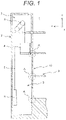
- an elevator device 1 includes a car 4, a counterweight 5, and a main rope 6 in a hoistway 3 of a building 2, and includes a hoist 8 in a machine room 7 of the building 2.
- the main rope 6 having one end connected to the car 4, and the other end connected to the counterweight 5 is hoisted using the hoist 8 so that the car 4 can be moved to an arbitrary floor.
- a landing door 10 to be operated in association with opening and closing operations of a car door of the car 4 is provided on a landing 9 of each floor at a side of the hoistway 3.
- a lower end of the landing door 10 is slidably supported by a landing sill device A to be described later.
- Figure 2 is a front view of the elevator landing sill device as illustrated in Figure 1 , and a periphery of the device.
- Figure 3 is a side sectional view of an enlarged part of the elevator landing sill device as illustrated in Figure 2 .
- the elevator landing sill device A includes a landing sill 12 which is provided along a lower edge 11 of a landing opening, and guides opening and closing operations of the landing door 10.
- a hoistway wall 3a at the landing opening side has multiple fixtures 13, for example, three fixtures (13A, 13B, 13C) arrayed along the longitudinal direction of the landing sill 12.
- a first fastener 14 serves to fix each of the fixtures 13 to the hoistway wall 3a.
- a second fastener 15 serves to fix the landing sill 12 to each of the fixtures 13.
- a third fastener 16 serves to join a wall-side member 13a to be fixed to the hoistway wall 3a using the first fastener 14 and a sill-side member 13b to which the landing sill 12 is fixed using the second fastener 15.
- each of the fixtures 13A, 13B, 13C has the same structure. A detailed explanation will be made with respect to the structure referring to Figure 3 , taking the fixture 13B as an example.
- the wall-side member 13a of the fixture 13B is fixed to the hoistway wall 3a using the first fastener 14 including an anchor bolt 14 and a nut 14b.
- the landing sill 12 is fixed to the sill-side member 13b using the second fastener 15 including a bolt 15a and a nut 15b.
- the wall-side member 13a and the sill-side member 13b are joined using the third fastener 16 including a bolt 16a and a nut 16b (see Figure 2 ) .
- the wall-side member 13a includes a plate-like fixing margin 13aa which is fixed to the hoistway wall 3a using the first fastener 14 while extending along the hoistway wall 3a, and a plate-like joining margin 13ab which is joined with the sill-side member 13b using the third fastener 16 while extending from the fixing margin 13aa parallel to the depth direction (left-right direction as shown in Figure 3 ) of the hoistway 3 and height direction.
- the sill-side member 13b includes a plate-like joining margin 13bb which is joined using the third fastener 16 with the joining margin 13ab of the wall-side member 13a while being overlaid therewith, and a plate-like mounting margin 13ba which extends from the joining margin 13bb parallel to the left-right direction and the depth direction of the hoistway 3, to which the landing sill 12 is fastened using the second fastener 15.
- the fixing margin 13aa of the wall-side member 13a has a bolt insertion part 13ac through which the anchor bolt 14a of the first fastener 14 is inserted.
- the bolt insertion part 13ac is formed into a long hole which is long in the longitudinal direction (y-direction; left-right direction of Figure 2 ) of the landing sill 12. This allows change in the position of the anchor bolt 14a to the fixing margin 13aa in the longitudinal direction of the landing sill 12.
- multiple bolt insertion parts 13ac for example, three bolt insertion parts are arranged at equal intervals in the height direction (z-direction).
- the joining margin 13ab of the wall-side member 13a has a bolt insertion part 13ad through which the bolt 16a of the third fastener 16 is inserted.
- the bolt insertion part 13ad is formed into a long hole which is long in the depth direction (x-direction) of the hoistway 3. This allows change in the relative position between the bolt 16a and the wall-side member 13a in the depth direction of the hoistway 3.
- the joining margin 13bb of the sill-side member 13b has a bolt insertion part 13bc through which the bolt 16a of the third fastener 16 is inserted.
- the bolt insertion part 13bc is formed into a long hole which is long in the height direction (z-direction). This allows change in the relative position between the bolt 16a and the sill-side member 13b in the height direction.
- the wall-side member 13a and the sill-side member 13b are joined by means of the bolt insertion parts 13ad, 13bc so that the position of the sill-side member 13b can be adjusted in the height direction and the depth direction (x-direction; left-right direction of Figure 3 ) of the hoistway 3.
- the partition member 20 is disposed to seal the gap between the landing sill 12 and the hoistway wall 3a of the building 2.
- the partition member 20 is formed into a hinge structure constituted by a center plate 21, a building-side mount part 22, and a sill-side mount part 23.
- the building-side mount part 22 and the sill-side mount part 23 are rotatably attached to the respective sides of the center plate 21.
- the building-side mount part 22 is fixed to the hoistway wall 3a of the building using an anchor bolt (building-side fastener) 24.
- the sill-side mount part 23 is attached to the lower surface of the landing sill 12 using a bolt 25 (sill-side fastener) 25.
- the partition member 20 seals the gap between the landing sill 12 and the hoistway wall 3a of the building 2 to prevent outflow of the mortar 30 poured to make the upper surface of the landing sill 12 flush with the landing floor surface to the inside of the hoistway 3 (see Figure 1 ).
- a floor surface finishing member such as carpet, tile, flooring for forming the floor surface is laid on the upper surface of the mortar 30. Since the heavy load such as a cart other than humans may pass through the landing opening, the thickness or strength of the partition member 20 is determined so that its deformation is kept within an allowable value despite passage of the maximum permissible heavy load conveyable by the elevator.
- a three-way frame 31 is provided at the landing opening.
- the inner width dimension of the three-way frame 31 is substantially the same as the width dimension of the landing opening.
- the width of the partition member 20 is set to be substantially the same as the width dimension of the landing opening.
- Figure 4 is a side view representing a structure of the partition member 20 as illustrated in Figure 3 .
- the partition member 20 includes the center plate 21, the building-side mount part 22 attached to the hoistway wall 3a, and the sill-side mount part 23 attached to the lower surface of the landing sill 12.
- the building-side mount part 22 is rotatably attached to one end of the center plate 21 via a shaft 26, and the sill-side mount part 23 is rotatably attached to the other end of the center plate 21 via a shaft 27.
- the sill-side mount part 23 is fixed to a predetermined position of the lower surface of the landing sill 12 using the bolt 25.
- the sill-side mount part 23 is structured to be in contact with the landing sill over an entire range in contact with the landing sill 12 in the left-right direction (y-direction) so as not to generate the gap.
- the building-side mount part 22 is structured to be in contact with the hoistway wall 3a over an entire range in contact with the hoistway wall 3a in the left-right direction (y-direction) so as not to generate the gap. If the gap is unavoidably generated between the sill-side mount part 23 and the landing sill 12, or between the building-side mount part 22 and the hoistway wall 3a, it is preferable to provide the gap sealing member, for example, plastic sheet.
- a positional relationship between the landing sill 12 and the building 2 is not constant.
- Dimension error of the building 2 makes the dimension between the hoistway wall 3a and the landing sill 12 variable.
- the partition member 20 of the example allows the position of the building-side mount part 22 to be freely changed by means of the two shafts 26, 27 in accordance with the dimension between the hoistway wall 3a and the landing sill 12.
- the anchor bolt 24 is driven into the hoistway wall 3a at a position corresponding to the building-side mount part 22 so that the building-side mount part 22 is vertically moved to be brought into tight contact with the hoistway wall 3a, and the anchor bolt 24 ensures to fix the building-side mount part 22 to the hoistway wall 3a, irrespective of the dimension between the hoistway wall 3a and the landing sill 12.
- the partition member 20 After fixing the partition member 20 to the hoistway wall 3a and the landing sill 12, as illustrated in Figures 3 and 4 , the partition member 20 securely prevents outflow of the mortar 30 in the pouring process to the inside of the hoistway 3.
- Figure 5 is an explanatory view of the structure of the partition member 20, indicating a state before assembling the center plate 21, the building-side mount part 22, and the sill-side mount part 23.
- Figure 6 indicates a state where the center plate 21, the building-side mount part 22, and the sill-side mount part 23 have been assembled.
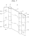
- Figure 7 is a perspective view of the assembled partition member 20.
- FIG. 5 illustrates, multiple tubes 21a (two on each side in the example) through which the shafts 26, 27 penetrate are provided on the respective sides of the center plate 21.
- the building-side mount part 22 and the sill-side mount part 23 include multiple tubes 22a, 23a (three in the example) through which the shafts 26, 27 penetrate, respectively on sides connected to the center plate 21 at positions which are not interfered with the tubes 21a.
- bolt holes 22b, 23b are formed along the longitudinal direction of the partition member 20 (longitudinal direction of the landing sill 12; y-direction).
- the bolt hole 22b accommodates penetration of the anchor bolt 24 as illustrated in Figure 4
- the bolt hole 23b accommodates penetration of the bolt 25 as illustrated in Figure 4 .
- the center plate 21, the building-side mount part 22, and the sill-side mount part 23 are combined as illustrated in Figure 6 .
- the building-side mount part 22 and the sill-side mount part 23 are rotatably assembled with the center plate 21 by means of the shafts 26, 27.
- Figure 7 is a perspective view of the assembled partition member 20.
- the shaft 26 extending from one end to the other end of the partition member 20 penetrates through the tubes 22a of the building-side mount part 22 and the tubes 21a of the center plate 21 so that the building-side mount part 22 is rotatably attached to the center plate 21.
- the shaft 27 extending from one end to the other end of the partition member 20 penetrates through the tubes 23a of the sill-side mount part 23 and the tubes 21a of the center plate 21 so that the sill-side mount part 23 is rotatably attached to the center plate 21.
- Each of the shafts 26, 27 is provided with a stopper for preventing detachment from the partition member 20.
- Figure 8 is an explanatory view of an operation of the partition member 20 in the case of a small gap between the building 2 and the landing sill 12.
- the building-side mount part 22 is moved downward along the hoistway wall 3a to be in tight contact therewith while having the sill-side mount part 23 attached to the landing sill 12.
- the anchor bolt 24 is driven into the hoistway wall 3a at the position corresponding to the bolt hole 22b of the building-side mount part 22.
- the anchor bolt 24 securely fixes the building-side mount part 22 to the hoistway wall 3a in the tight contact state.
- Figure 9 is an explanatory view of an operation of the partition member 20 in the case of a large gap between the building 2 and the landing sill 12.
- the building-side mount part 22 is moved upward to be higher than the position as illustrated in Figure 8 by means of the shafts 26, 27 so that the building-side mount part 22 is brought into tight contact with the hoistway wall 3a.
- the building-side mount part 22 can be securely in tight contact with the hoistway wall 3a.
- the anchor bolt 24 is driven into the hoistway wall 3a at the position corresponding to the bolt hole 22b of the building-side mount part 22.
- the anchor bolt 24 allows the building-side mount part 22 to be securely fixed to the hoistway wall 3a in the tight contact state.
- the partition member 20 of the example allows the position of the building-side mount part 22 to be freely changed by means of the two shafts 26, 27 in accordance with the dimension between the hoistway wall 3a and the landing sill 12.
- the anchor bolt 24 is driven into the building 2 by positioning the building-side mount part 22 to be in tight contact with the hoistway wall 3a so that the partition member 20 can be constantly fixed in tight contact with the hoistway wall 3a and the landing sill 12 irrespective of the dimension therebetween.
- the example ensures to seal the gap between the hoistway wall 3a and the landing sill 12 easily and securely.
- the shaft 26 for connecting the center plate 21 with the building-side mount part 22 of the partition member 20, and the shaft 27 for connecting the center plate 21 with the sill-side mount part 23 are separately formed as individual members.
- the partition member may be configured as illustrated in Figure 10.
- Figure 10 is an explanatory view of another example of the partition member 20, which corresponds to Figure 5 .
- the partition member 20 as illustrated in Figure 10 has multiple tubes 21a on both sides (two for each side) of the center plate 21 for accommodating insertion of the shafts.
- Multiple tubes 22a, 23a are attached to the building-side mount part 22 and the sill-side mount part 23 at positions where those tubes are not interfered with the tubes 21a of the center plate 21.
- Shaft parts 22c, 23c to be inserted into the tubes 21a are fixed to the tubes 22a, 23a, respectively.
- the above-described structure allows the building-side mount part 22 and the sill-side mount part 23 to be rotatably attached to the center plate 21 by inserting the shaft parts 22c, 23c into the tubes 21a of the center plate 21, respectively.
- the shaft part 22c of the tube 22a of the building-side mount part 22 is inserted between the tubes 21a of the center plate 21 and the tubes 21a of the center plate 21, it is necessary to form an axial gap having the length equal to or longer than the length of the shaft part 22c protruding from the tube 22a so that the shaft part 22c can be inserted in the tube 21a.
- the length of the shaft part of the tube 22a or the tube 21a is shorter than that illustrated in Figure 5 , and a gap is formed between the tube 22a and the tube 21a after assembly.
- the partition member 20 may be provided with the gap sealing member.
- the bolt holes 22b, 23b formed in the building-side mount part 22 and the sill-side mount part 23 of the partition member 20 are formed into circular shapes. It is possible to form those bolt holes into long holes which are long in the short-length direction (direction perpendicular to the shafts 26, 27) of the building-side mount part 22 and the sill-side mount part 23 as illustrated in Figure 11.
- Figure 11 is an explanatory view of still another example of the partition member 20, which corresponds to Figure 6 .
- the bolt holes 22b, 23b are formed into long holes which are long in the short-length direction of the building-side mount part 22 and the sill-side mount part 23. Those holes allow the relative position between the anchor bolt 24 and the bolt hole 22b, or between the bolt 25 and the bolt hole 23b to be freely changed in accordance with the dimension between the hoistway wall 3a and the landing sill 12 in spite of variation in the dimension between the hoistway wall 3a and the landing sill 12.
- This makes it possible to bring the building-side mount part 22 into tight contact with the hoistway wall 3a, and the sill-side mount part 23 into tight contact with the landing sill 12. Accordingly, it is possible to fix the building-side mount part 22 to the hoistway wall 3a, and the sill-side mount part 23 to the landing sill 12 each in the tight contact state even after driving the anchor bolt 24 into the building 2.
- the example as illustrated in Figure 11 allows the partition member 20 to be constantly fixed to the hoistway wall 3a and the landing sill 12 in the tight contact state irrespective of the dimension between the hoistway wall 3a and the landing sill 12 even after driving the anchor bolt 24 into the building 2. Accordingly, in the example as illustrated in Figure 11 , it is possible to seal the gap between the hoistway wall 3a and the landing sill 12 further easily and securely.
- the partition member 20 ensures to seal the gap between the hoistway wall 3a and the landing sill 12. It is therefore possible to prevent inflow of the mortar 30 to be poured into the landing floor side of the landing sill 12 for finishing the landing floor to the inside of the hoistway 3 from the gap between the hoistway wall 3a and the landing sill 12.
- the present invention includes various modifications without being limited to the foregoing example.
- the partition member 20 is composed of three members, that is, the center plate 21, the building-side mount part 22, and the sill-side mount part 23.
- the partition member 20 may be composed of four or more members in total including multiple center plates 21. It is possible to use the corrugated plate as the center plate 21 instead of the flat plate.
- the building-side mount part 22 and the sill-side mount part 23 may be structured to have only mount parts while leaving peripheries of the bolt holes 22b, 23b with no limitation to rectangular plates.
- the building-side mount part 22 is fixed to the hoistway wall 3a, and the sill-side mount part 23 is fixed to the lower surface of the landing sill 12. It is also possible to fix the building-side mount part 22 to the upper surface of the building 2, and the sill-side mount part 23 to the side surface of the landing sill 12 with no limitation to those fixing positions.
Landscapes
- Elevator Door Apparatuses (AREA)
Abstract
Description
- The present invention relates to an elevator landing sill device for fixing a landing sill to a hoistway wall. More specifically, the present invention relates to an elevator landing sill device configured to seal the gap between the hoistway wall and the landing sill to prevent inflow of mortar used for finishing the landing floor from the gap to the inside of the hoistway, and relates to an elevator device equipped with the elevator landing sill device.
- The generally employed elevator landing sill device has been disclosed in
Japanese Patent Application Laid-Open No. 2009-84029 -
PTL 1 discloses the elevator landing sill device as described inclaim 1 to be cited below. The elevator landing sill device includes a landing sill provided along a lower edge of a landing opening for guiding opening and closing operations of a landing door, a fixture that is fixed to a hoistway wall at the landing opening side using a first fastener including bolts, to which the landing sill is fixed using a second fastener including bolts, and a partition member that is held between the fixture and the landing sill, and fastened to the fixture jointly with the landing sill using the second fastener. The partition member seals a gap between the hoistway wall and the landing sill to prevent inflow of mortar used for finishing the landing floor to the inside of the hoistway from the gap. The fixture includes a wall-side member that is fixed to the hoistway wall using the first fastener, and a sill-side member to which the landing sill is fixed using the second fastener. The wall-side member and the sill-side member are joined to allow positional adjustment of the sill-side member in a height direction and a depth direction of the hoistway. The partition member includes a first held plate to be held between the hoistway wall and the wall-side member, and a second held plate to be held between the sill-side member and the landing sill. The first held plate has a first relief part formed to accommodate insertion of the bolt as the first fastener, and to allow change in the position of the first held plate to the bolt in the height direction. The second held plate has a second relief part formed to accommodate insertion of the bolt as the second fastener, and to allow change in the position of the bolt to the second held plate in the depth direction of the hoistway. - PTL 1:
Japanese Patent Application Laid-Open No. 2009-84029 - However, the landing sill device as disclosed in
PTL 1 has the first held plate and the second held plate fixedly combined to constitute the partition member, and the first held plate is fixed to the vertical surface of the hoistway wall using the fastener. This may cause difficulty in provision of the partition member in the presence of a large dimension error of the building. There may be the case where the second held plate constituting the partition member protrudes from the side surface of the landing sill toward the hoistway, resulting in the problem of contact with the car. - An object of the present invention is to provide the elevator landing sill device, and the elevator device equipped with the same. Specifically, the elevator landing sill device can easily seal the gap between the landing sill and the hoistway wall without causing protrusion of the partition member toward the hoistway side even in the presence of the large dimension error of the building in the height direction and the depth direction of the hoistway so that outflow of the mortar to the inside of the hoistway can be prevented.
- In order to attain the above-described object, the present invention provides an elevator landing sill device having a hoistway provided in a building for moving a car up and down, a landing opening formed at a hoistway side of the building, a landing sill disposed along a lower edge of the landing opening for guiding opening and closing operations of a landing door, and a fixture that is fixed to a hoistway wall of the building, having an upper part to which the landing sill is attached. The elevator landing sill device includes a partition member for sealing a gap between the landing sill and the hoistway wall. The partition member includes a center plate, a building-side mount part attached to one end of the center plate, a sill-side mount part attached to the other end of the center plate, a building-side rotating part for rotatably fixing the center plate and the building-side mount part, and a sill-side rotating part for rotatably fixing the center plate and the sill-side mount part. The device further includes a building-side fastener for fixing the building-side mount part to the building, and a sill-side fastener for fixing the sill-side mount part to the landing sill.
- The present invention also provides an elevator device including a car which moves up and down in a hoistway of a building, a hoist for moving the car up and down, and an elevator landing sill device which is provided along a lower edge of a landing opening at a hoistway side of the building for guiding opening and closing operations of a landing door. The elevator landing sill device is the elevator landing sill device as described above.
- The present invention provides the elevator landing sill device, and the elevator device equipped with the same. The elevator landing sill device is effective for easily sealing the gap between the landing sill and the hoistway wall without causing protrusion of the partition member toward the hoistway side even in the presence of the large dimension error of the building in the height direction and the depth direction of the hoistway so that outflow of the mortar to the inside of the hoistway can be prevented.
-
-
Figure 1 is a schematic sectional view of an elevator device. -
Figure 2 is a front view of an elevator landing sill device as illustrated inFigure 1 , and a periphery of the device. -
Figure 3 is a side sectional view of an enlarged part of the elevator landing sill device as illustrated inFigure 2 . -
Figure 4 is a side view representing a structure of a partition member as illustrated inFigure 3 . -
Figure 5 is an explanatory view of the structure of the partition member, indicating a state before assembling a center plate, a building-side mount part, and a sill-side mount part. -
Figure 6 is an explanatory view of the structure of the partition member, indicating a state after assembling the center plate, the building-side mount part, and the sill-side mount part. -
Figure 7 is a perspective view of the partition member. -
Figure 8 is an explanatory view of an operation of the partition member in the case of a small gap between the building and the landing sill. -
Figure 9 is an explanatory view of the operation of the partition member in the case of a large gap between the building and the landing sill. -
Figure 10 is an explanatory view of another example of the partition member, which corresponds toFigure 5 . -
Figure 11 is an explanatory view of still another example of the partition member, which corresponds toFigure 6 . - Specific examples of the elevator landing sill device according to the present invention will be described referring to the drawings. In the drawings, the same or similar parts are designated with the same codes.
- Referring to the schematic sectional view of
Figure 1 , an explanation will be made with respect to a structure of a generally employed elevator device to which the present invention is applied. AsFigure 1 illustrates, anelevator device 1 includes acar 4, acounterweight 5, and amain rope 6 in ahoistway 3 of abuilding 2, and includes ahoist 8 in amachine room 7 of thebuilding 2. Themain rope 6 having one end connected to thecar 4, and the other end connected to thecounterweight 5 is hoisted using thehoist 8 so that thecar 4 can be moved to an arbitrary floor. - A
landing door 10 to be operated in association with opening and closing operations of a car door of thecar 4 is provided on a landing 9 of each floor at a side of thehoistway 3. A lower end of thelanding door 10 is slidably supported by a landing sill device A to be described later. - The following explanation will be made by defining the depth direction of the
hoistway 3 as x-direction, the opening/closing direction of thelanding door 10 as y-direction, and the lifting/lowering direction of thecar 4 as z-direction. - Referring to
Figures 2 and3 , an explanation will be made with respect to the elevator landing sill device on each floor of the elevator device as illustrated inFigure 1 .Figure 2 is a front view of the elevator landing sill device as illustrated inFigure 1 , and a periphery of the device.Figure 3 is a side sectional view of an enlarged part of the elevator landing sill device as illustrated inFigure 2 . - As
Figure 2 illustrates, the elevator landing sill device A according to Example 1 includes alanding sill 12 which is provided along alower edge 11 of a landing opening, and guides opening and closing operations of thelanding door 10. Ahoistway wall 3a at the landing opening side hasmultiple fixtures 13, for example, three fixtures (13A, 13B, 13C) arrayed along the longitudinal direction of thelanding sill 12. Afirst fastener 14 serves to fix each of thefixtures 13 to thehoistway wall 3a. Asecond fastener 15 serves to fix thelanding sill 12 to each of thefixtures 13. Athird fastener 16 serves to join a wall-side member 13a to be fixed to thehoistway wall 3a using thefirst fastener 14 and a sill-side member 13b to which thelanding sill 12 is fixed using thesecond fastener 15. - Each of the
fixtures Figure 3 , taking thefixture 13B as an example. AsFigure 3 illustrates, the wall-side member 13a of thefixture 13B is fixed to thehoistway wall 3a using thefirst fastener 14 including ananchor bolt 14 and anut 14b. Thelanding sill 12 is fixed to the sill-side member 13b using thesecond fastener 15 including a bolt 15a and anut 15b. The wall-side member 13a and the sill-side member 13b are joined using thethird fastener 16 including a bolt 16a and a nut 16b (seeFigure 2 ) . - The wall-
side member 13a includes a plate-like fixing margin 13aa which is fixed to thehoistway wall 3a using thefirst fastener 14 while extending along thehoistway wall 3a, and a plate-like joining margin 13ab which is joined with the sill-side member 13b using thethird fastener 16 while extending from the fixing margin 13aa parallel to the depth direction (left-right direction as shown inFigure 3 ) of thehoistway 3 and height direction. - The sill-
side member 13b includes a plate-like joining margin 13bb which is joined using thethird fastener 16 with the joining margin 13ab of the wall-side member 13a while being overlaid therewith, and a plate-like mounting margin 13ba which extends from the joining margin 13bb parallel to the left-right direction and the depth direction of thehoistway 3, to which thelanding sill 12 is fastened using thesecond fastener 15. - The fixing margin 13aa of the wall-
side member 13a has a bolt insertion part 13ac through which the anchor bolt 14a of thefirst fastener 14 is inserted. AsFigure 2 illustrates, the bolt insertion part 13ac is formed into a long hole which is long in the longitudinal direction (y-direction; left-right direction ofFigure 2 ) of the landingsill 12. This allows change in the position of the anchor bolt 14a to the fixing margin 13aa in the longitudinal direction of the landingsill 12. AsFigure 2 illustrates, multiple bolt insertion parts 13ac, for example, three bolt insertion parts are arranged at equal intervals in the height direction (z-direction). - The joining margin 13ab of the wall-
side member 13a has a bolt insertion part 13ad through which the bolt 16a of thethird fastener 16 is inserted. The bolt insertion part 13ad is formed into a long hole which is long in the depth direction (x-direction) of thehoistway 3. This allows change in the relative position between the bolt 16a and the wall-side member 13a in the depth direction of thehoistway 3. - The joining margin 13bb of the sill-
side member 13b has a bolt insertion part 13bc through which the bolt 16a of thethird fastener 16 is inserted. The bolt insertion part 13bc is formed into a long hole which is long in the height direction (z-direction). This allows change in the relative position between the bolt 16a and the sill-side member 13b in the height direction. In other words, the wall-side member 13a and the sill-side member 13b are joined by means of the bolt insertion parts 13ad, 13bc so that the position of the sill-side member 13b can be adjusted in the height direction and the depth direction (x-direction; left-right direction ofFigure 3 ) of thehoistway 3. - As
Figures 2 and3 illustrate, thepartition member 20 is disposed to seal the gap between the landingsill 12 and thehoistway wall 3a of thebuilding 2. Thepartition member 20 is formed into a hinge structure constituted by acenter plate 21, a building-side mount part 22, and a sill-side mount part 23. The building-side mount part 22 and the sill-side mount part 23 are rotatably attached to the respective sides of thecenter plate 21. The building-side mount part 22 is fixed to thehoistway wall 3a of the building using an anchor bolt (building-side fastener) 24. The sill-side mount part 23 is attached to the lower surface of the landingsill 12 using a bolt 25 (sill-side fastener) 25. Thepartition member 20 seals the gap between the landingsill 12 and thehoistway wall 3a of thebuilding 2 to prevent outflow of themortar 30 poured to make the upper surface of the landingsill 12 flush with the landing floor surface to the inside of the hoistway 3 (seeFigure 1 ). - Although not shown in the drawing, a floor surface finishing member such as carpet, tile, flooring for forming the floor surface is laid on the upper surface of the
mortar 30. Since the heavy load such as a cart other than humans may pass through the landing opening, the thickness or strength of thepartition member 20 is determined so that its deformation is kept within an allowable value despite passage of the maximum permissible heavy load conveyable by the elevator. - Referring to
Figures 2 and3 , a three-way frame 31 is provided at the landing opening. The inner width dimension of the three-way frame 31 is substantially the same as the width dimension of the landing opening. The width of thepartition member 20 is set to be substantially the same as the width dimension of the landing opening. - The specific structure of the
partition member 20 will be described referring toFigures 4 to 7 . -
Figure 4 is a side view representing a structure of thepartition member 20 as illustrated inFigure 3 . Thepartition member 20 includes thecenter plate 21, the building-side mount part 22 attached to thehoistway wall 3a, and the sill-side mount part 23 attached to the lower surface of the landingsill 12. The building-side mount part 22 is rotatably attached to one end of thecenter plate 21 via ashaft 26, and the sill-side mount part 23 is rotatably attached to the other end of thecenter plate 21 via ashaft 27. - The sill-
side mount part 23 is fixed to a predetermined position of the lower surface of the landingsill 12 using thebolt 25. Preferably, the sill-side mount part 23 is structured to be in contact with the landing sill over an entire range in contact with the landingsill 12 in the left-right direction (y-direction) so as not to generate the gap. Preferably, the building-side mount part 22 is structured to be in contact with thehoistway wall 3a over an entire range in contact with thehoistway wall 3a in the left-right direction (y-direction) so as not to generate the gap. If the gap is unavoidably generated between the sill-side mount part 23 and the landingsill 12, or between the building-side mount part 22 and thehoistway wall 3a, it is preferable to provide the gap sealing member, for example, plastic sheet. - A positional relationship between the landing
sill 12 and thebuilding 2 is not constant. Dimension error of thebuilding 2 makes the dimension between thehoistway wall 3a and the landingsill 12 variable. Even in the state where the sill-side mount part 23 is fixed to the landingsill 12, thepartition member 20 of the example allows the position of the building-side mount part 22 to be freely changed by means of the twoshafts hoistway wall 3a and the landingsill 12. Accordingly, theanchor bolt 24 is driven into thehoistway wall 3a at a position corresponding to the building-side mount part 22 so that the building-side mount part 22 is vertically moved to be brought into tight contact with thehoistway wall 3a, and theanchor bolt 24 ensures to fix the building-side mount part 22 to thehoistway wall 3a, irrespective of the dimension between thehoistway wall 3a and the landingsill 12. - After fixing the
partition member 20 to thehoistway wall 3a and the landingsill 12, as illustrated inFigures 3 and4 , thepartition member 20 securely prevents outflow of themortar 30 in the pouring process to the inside of thehoistway 3. - An explanation will be made with respect to a structure of the
partition member 20 referring toFigures 5 to 7 .Figure 5 is an explanatory view of the structure of thepartition member 20, indicating a state before assembling thecenter plate 21, the building-side mount part 22, and the sill-side mount part 23.Figure 6 indicates a state where thecenter plate 21, the building-side mount part 22, and the sill-side mount part 23 have been assembled.Figure 7 is a perspective view of the assembledpartition member 20. - As
Figure 5 illustrates,multiple tubes 21a (two on each side in the example) through which theshafts center plate 21. The building-side mount part 22 and the sill-side mount part 23 includemultiple tubes shafts center plate 21 at positions which are not interfered with thetubes 21a. - Multiple bolt holes 22b, 23b (three for each mount part in the example) are formed along the longitudinal direction of the partition member 20 (longitudinal direction of the landing
sill 12; y-direction). Thebolt hole 22b accommodates penetration of theanchor bolt 24 as illustrated inFigure 4 , and thebolt hole 23b accommodates penetration of thebolt 25 as illustrated inFigure 4 . - The
center plate 21, the building-side mount part 22, and the sill-side mount part 23 are combined as illustrated inFigure 6 . The building-side mount part 22 and the sill-side mount part 23 are rotatably assembled with thecenter plate 21 by means of theshafts -
Figure 7 is a perspective view of the assembledpartition member 20. Theshaft 26 extending from one end to the other end of thepartition member 20 penetrates through thetubes 22a of the building-side mount part 22 and thetubes 21a of thecenter plate 21 so that the building-side mount part 22 is rotatably attached to thecenter plate 21. Theshaft 27 extending from one end to the other end of thepartition member 20 penetrates through thetubes 23a of the sill-side mount part 23 and thetubes 21a of thecenter plate 21 so that the sill-side mount part 23 is rotatably attached to thecenter plate 21. Each of theshafts partition member 20. - Referring to
Figures 8 and 9 , an explanation will be made with respect to operations of thepartition member 20 when it is attached between thebuilding 2 and the landingsill 12. -
Figure 8 is an explanatory view of an operation of thepartition member 20 in the case of a small gap between thebuilding 2 and the landingsill 12. In the case of the small dimension between thehoistway wall 3a and the landingsill 12 because of the building dimension error, the building-side mount part 22 is moved downward along thehoistway wall 3a to be in tight contact therewith while having the sill-side mount part 23 attached to the landingsill 12. In the above-described state, theanchor bolt 24 is driven into thehoistway wall 3a at the position corresponding to thebolt hole 22b of the building-side mount part 22. Theanchor bolt 24 securely fixes the building-side mount part 22 to thehoistway wall 3a in the tight contact state. -
Figure 9 is an explanatory view of an operation of thepartition member 20 in the case of a large gap between thebuilding 2 and the landingsill 12. In the case of the large dimension between thehoistway wall 3a and the landingsill 12, the building-side mount part 22 is moved upward to be higher than the position as illustrated inFigure 8 by means of theshafts side mount part 22 is brought into tight contact with thehoistway wall 3a. The building-side mount part 22 can be securely in tight contact with thehoistway wall 3a. In the tight contact state, theanchor bolt 24 is driven into thehoistway wall 3a at the position corresponding to thebolt hole 22b of the building-side mount part 22. Theanchor bolt 24 allows the building-side mount part 22 to be securely fixed to thehoistway wall 3a in the tight contact state. - The
partition member 20 of the example allows the position of the building-side mount part 22 to be freely changed by means of the twoshafts hoistway wall 3a and the landingsill 12. Theanchor bolt 24 is driven into thebuilding 2 by positioning the building-side mount part 22 to be in tight contact with thehoistway wall 3a so that thepartition member 20 can be constantly fixed in tight contact with thehoistway wall 3a and the landingsill 12 irrespective of the dimension therebetween. The example ensures to seal the gap between thehoistway wall 3a and the landingsill 12 easily and securely. - In the foregoing example, the
shaft 26 for connecting thecenter plate 21 with the building-side mount part 22 of thepartition member 20, and theshaft 27 for connecting thecenter plate 21 with the sill-side mount part 23 are separately formed as individual members. The partition member may be configured as illustrated inFigure 10. Figure 10 is an explanatory view of another example of thepartition member 20, which corresponds toFigure 5 . - The
partition member 20 as illustrated inFigure 10 hasmultiple tubes 21a on both sides (two for each side) of thecenter plate 21 for accommodating insertion of the shafts.Multiple tubes side mount part 22 and the sill-side mount part 23 at positions where those tubes are not interfered with thetubes 21a of thecenter plate 21.Shaft parts tubes 21a are fixed to thetubes - The above-described structure allows the building-
side mount part 22 and the sill-side mount part 23 to be rotatably attached to thecenter plate 21 by inserting theshaft parts tubes 21a of thecenter plate 21, respectively. - Between the opposite side to the
shaft part 22c of thetube 22a of the building-side mount part 22 to be inserted between thetubes 21a of thecenter plate 21 and thetubes 21a of thecenter plate 21, it is necessary to form an axial gap having the length equal to or longer than the length of theshaft part 22c protruding from thetube 22a so that theshaft part 22c can be inserted in thetube 21a. In this example, the length of the shaft part of thetube 22a or thetube 21a is shorter than that illustrated inFigure 5 , and a gap is formed between thetube 22a and thetube 21a after assembly. - Similarly, between the opposite side to the
shaft part 22c of thetube 23a of the sill-side mount part 23 inserted between thetubes 21a of thecenter plate 21 and thetubes 21a of thecenter plate 21, it is necessary to form an axial gap having the length equal to or longer than the length of theshaft part 23c protruding from thetube 23a so that theshaft part 23c can be inserted in thetube 21a. - In the case of potential leakage of the
mortar 30 to the inside of thehoistway 3 from the gap in the pouring process even in the presence of thepartition member 20 between thebuilding 2 and the landingsill 12, thepartition member 20 may be provided with the gap sealing member. - In the foregoing example, the bolt holes 22b, 23b formed in the building-
side mount part 22 and the sill-side mount part 23 of thepartition member 20 are formed into circular shapes. It is possible to form those bolt holes into long holes which are long in the short-length direction (direction perpendicular to theshafts 26, 27) of the building-side mount part 22 and the sill-side mount part 23 as illustrated inFigure 11. Figure 11 is an explanatory view of still another example of thepartition member 20, which corresponds toFigure 6 . - As
Figure 11 illustrates, the bolt holes 22b, 23b are formed into long holes which are long in the short-length direction of the building-side mount part 22 and the sill-side mount part 23. Those holes allow the relative position between theanchor bolt 24 and thebolt hole 22b, or between thebolt 25 and thebolt hole 23b to be freely changed in accordance with the dimension between thehoistway wall 3a and the landingsill 12 in spite of variation in the dimension between thehoistway wall 3a and the landingsill 12. This makes it possible to bring the building-side mount part 22 into tight contact with thehoistway wall 3a, and the sill-side mount part 23 into tight contact with the landingsill 12. Accordingly, it is possible to fix the building-side mount part 22 to thehoistway wall 3a, and the sill-side mount part 23 to the landingsill 12 each in the tight contact state even after driving theanchor bolt 24 into thebuilding 2. - The example as illustrated in
Figure 11 allows thepartition member 20 to be constantly fixed to thehoistway wall 3a and the landingsill 12 in the tight contact state irrespective of the dimension between thehoistway wall 3a and the landingsill 12 even after driving theanchor bolt 24 into thebuilding 2. Accordingly, in the example as illustrated inFigure 11 , it is possible to seal the gap between thehoistway wall 3a and the landingsill 12 further easily and securely. - In the foregoing example, it is possible to easily bring the building-
side mount part 22 of thepartition member 20 into tight contact with thehoistway wall 3a, and the sill-side mount part 23 into tight contact with the lower surface of the landingsill 12 in spite of variation in the dimension between thehoistway wall 3a and the landingsill 12. Thepartition member 20 ensures to seal the gap between thehoistway wall 3a and the landingsill 12. It is therefore possible to prevent inflow of themortar 30 to be poured into the landing floor side of the landingsill 12 for finishing the landing floor to the inside of thehoistway 3 from the gap between thehoistway wall 3a and the landingsill 12. - In the example, it is possible to seal the gap between the
hoistway wall 3a and the landingsill 12 by easily making thepartition member 20 adaptable to the relatively large dimension error of the building in the height direction (z-direction) and the depth direction of the hoistway 3 (x-direction). This may solve the conventional problem of protrusion of the partition member toward thehoistway 3 from the side surface of the landing sill. - The present invention includes various modifications without being limited to the foregoing example.
- In the example, the
partition member 20 is composed of three members, that is, thecenter plate 21, the building-side mount part 22, and the sill-side mount part 23. Thepartition member 20 may be composed of four or more members in total includingmultiple center plates 21. It is possible to use the corrugated plate as thecenter plate 21 instead of the flat plate. The building-side mount part 22 and the sill-side mount part 23 may be structured to have only mount parts while leaving peripheries of the bolt holes 22b, 23b with no limitation to rectangular plates. - In the example, as
Figures 3 and4 illustrate, the building-side mount part 22 is fixed to thehoistway wall 3a, and the sill-side mount part 23 is fixed to the lower surface of the landingsill 12. It is also possible to fix the building-side mount part 22 to the upper surface of thebuilding 2, and the sill-side mount part 23 to the side surface of the landingsill 12 with no limitation to those fixing positions. - The example has been described in detail for easy understanding of the present invention. Therefore, it is not necessarily limited to be configured to have all the components as described above.
-
- 1
- elevator device,
- 2
- building,
- 3
- hoistway,
- 3a
- hoistway wall,
- 4
- car,
- 5
- counterweight,
- 6
- main rope,
- 7
- machine room,
- 8
- hoist,
- 9
- landing,
- 10
- landing door,
- 11
- lower edge,
- 12
- landing sill,
- 13 (13A, 13B, 13C)
- fixture,
- 13a
- wall-side member,
- 13aa
- fixing margin,
- 13ab
- joining margin,
- 13ac, 13ad
- bolt insertion part,
- 13b
- sill-side member,
- 13ba
- mounting margin,
- 13bb
- joining margin,
- 13bc
- bolt insertion part,
- 14
- first fastener,
- 14a
- anchor bolt,
- 14b
- nut,
- 15
- second fastener,
- 15a
- bolt,
- 15b
- nut,
- 16
- third fastener,
- 16a
- bolt,
- 16b
- nut,
- 20
- partition member,
- 21
- center plate,
- 21a
- tube,
- 22
- building-side mount part,
- 22a
- tube,
- 22b
- bolt hole,
- 22c
- shaft part,
- 23
- sill-side mount part,
- 23a
- tube,
- 23b
- bolt hole,
- 23c
- shaft part,
- 24
- anchor bolt (building-side fastener),
- 25
- bolt (sill-side fastener),
- 26
- shaft (building-side rotating part),
- 27
- shaft (sill-side rotating part),
- 30
- mortar,
- 31
- three-way frame,
- A
- landing sill device
Claims (11)
- An elevator landing sill device including a hoistway provided in a building for moving a car up and down, a landing opening formed at a hoistway side of the building, a landing sill disposed along a lower edge of the landing opening for guiding opening and closing operations of a landing door, and a fixture that is fixed to a hoistway wall of the building, having an upper part to which the landing sill is attached, the elevator landing sill device comprising a partition member for sealing a gap between the landing sill and the hoistway wall,wherein the partition member includes a center plate, a building-side mount part attached to one end of the center plate, a sill-side mount part attached to the other end of the center plate, a building-side rotating part for rotatably fixing the center plate and the building-side mount part, and a sill-side rotating part for rotatably fixing the center plate and the sill-side mount part; anda building-side fastener for fixing the building-side mount part to the building, and a sill-side fastener for fixing the sill-side mount part to the landing sill are provided.
- The elevator landing sill device according to claim 1,
wherein the building-side mount part of the partition member is fixed to the hoistway wall of the building using the building-side fastener, and the sill-side mount part is attached to a lower surface of the landing sill using the sill-side fastener. - The elevator landing sill device according to claim 1,
wherein the partition member has its thickness or strength determined to keep deformation of the partition member within an allowable value in spite of passage of a maximum permissible heavy load conveyable by the elevator. - The elevator landing sill device according to claim 2,
wherein the partition member has the building-side mount part rotatably attached to the one end of the center plate via a shaft, and the sill-side mount part rotatably attached to the other end of the center plate via a shaft. - The elevator landing sill device according to claim 1,
wherein the sill-side mount part of the partition member is configured to be in contact with the landing sill over an entire range in a left-right direction, and the building-side mount part is configured to be in contact with the hoistway wall over an entire range in contact with the hoistway wall in the left-right direction. - The elevator landing sill device according to claim 1, comprising a member for sealing a gap generated between the sill-side mount part of the partition member and the landing sill, or a gap generated between the building-side mount part and the hoistway wall.
- The elevator landing sill device according to claim 4,
wherein multiple tubes through which the shafts penetrate are provided on both sides of the center plate of the partition member, and the building-side mount part and the sill-side mount part have multiple tubes through which the shafts penetrate on sides connected to the center plate, each at a position that is not interfered with the tubes of the center plate. - The elevator landing sill device according to claim 7,wherein the building-side fastener is an anchor bolt, and the sill-side fastener is a bolt; andthe building-side mount part of the partition member has multiple bolt holes which allow insertion of the anchor bolt in a longitudinal direction, and the sill-side mount part has multiple bolt holes which allow insertion of the bolt in the longitudinal direction.
- The elevator landing sill device according to claim 7,
wherein the partition member includes multiple tubes provided on both sides of the center plate, through which the shafts are inserted, each of the building-side mount part and the sill-side mount part is provided with multiple tubes at positions which are not interfered with the tubes of the center plate, shaft parts to be inserted into the tubes of the center plate are fixed to the tubes of the building-side mount part and the sill-side mount part, and the building-side mount part and the sill-side mount part are rotatably attached to the center plate by inserting the shaft parts into the tubes of the center plate. - The elevator landing sill device according to claim 8,
wherein the bolt holes formed in the building-side mount part and the sill-side mount part of the partition member are formed into long holes, each of which is long in a short-length direction of the building-side mount part or the sill-side mount part. - An elevator device comprising a car which moves up and down in a hoistway of a building, a hoist for moving the car up and down, and an elevator landing sill device which is provided along a lower edge of a landing opening at a hoistway side of the building for guiding opening and closing operations of a landing door,
wherein the elevator landing sill device is the elevator landing sill device according to any one of claims 1 to 10.
Applications Claiming Priority (1)
| Application Number | Priority Date | Filing Date | Title |
|---|---|---|---|
| PCT/JP2019/041129 WO2021075053A1 (en) | 2019-10-18 | 2019-10-18 | Elevator landing sill device and elevator device equipped with same |
Publications (3)
| Publication Number | Publication Date |
|---|---|
| EP4046952A1 true EP4046952A1 (en) | 2022-08-24 |
| EP4046952A4 EP4046952A4 (en) | 2023-06-28 |
| EP4046952B1 EP4046952B1 (en) | 2024-07-10 |
Family
ID=75537768
Family Applications (1)
| Application Number | Title | Priority Date | Filing Date |
|---|---|---|---|
| EP19948941.0A Active EP4046952B1 (en) | 2019-10-18 | 2019-10-18 | Elevator landing sill device and elevator device equipped with same |
Country Status (5)
| Country | Link |
|---|---|
| US (1) | US11866297B2 (en) |
| EP (1) | EP4046952B1 (en) |
| JP (1) | JP7279181B2 (en) |
| CN (1) | CN114585580B (en) |
| WO (1) | WO2021075053A1 (en) |
Family Cites Families (33)
| Publication number | Priority date | Publication date | Assignee | Title |
|---|---|---|---|---|
| US1051945A (en) * | 1912-10-29 | 1913-02-04 | Bernard Baumann | Safety device for elevators. |
| US2120081A (en) * | 1935-01-02 | 1938-06-07 | Elisha E Alexander | Elevator plate mechanism |
| US2739354A (en) * | 1952-06-12 | 1956-03-27 | Lewis J Pope | Elevator door bridge |
| JPS547649Y2 (en) * | 1973-04-25 | 1979-04-10 | ||
| JPS595024Y2 (en) * | 1976-02-12 | 1984-02-15 | 三菱電機株式会社 | Weir board at elevator landing |
| JPS52149740A (en) * | 1976-06-09 | 1977-12-13 | Hitachi Ltd | Elevator platform control device |
| JPS5950898B2 (en) | 1977-06-17 | 1984-12-11 | 松下精工株式会社 | Control circuit of heat pump air conditioner |
| JPS5485728U (en) * | 1977-11-30 | 1979-06-18 | ||
| JPS5485728A (en) | 1977-12-20 | 1979-07-07 | Canon Inc | Image forming device |
| JPS5913635B2 (en) * | 1978-09-05 | 1984-03-30 | 三菱電機株式会社 | elevator equipment |
| JPS59199981A (en) * | 1983-04-26 | 1984-11-13 | 株式会社東芝 | Elevator depot floor |
| US4579503A (en) * | 1983-11-02 | 1986-04-01 | Leyman Manufacturing Corp. | Sideloader elevator platform |
| JP2713013B2 (en) * | 1992-03-27 | 1998-02-16 | 三菱電機株式会社 | Mounting structure for elevator sill |
| US7788854B2 (en) * | 2002-09-03 | 2010-09-07 | Harold S. Friedman | Elevator entrance door sill pivotable into and out of elevator shaft via hinge connected support and alignment brackets |
| ATE480489T1 (en) * | 2003-09-18 | 2010-09-15 | Otis Elevator Co | ELEVATOR ARRANGEMENT WITH EXTENDABLE THRESHOLD |
| JP2009084029A (en) * | 2007-10-02 | 2009-04-23 | Hitachi Building Systems Co Ltd | Landing sill device of elevator |
| JP2013107768A (en) * | 2011-11-24 | 2013-06-06 | Hitachi Ltd | Elevator device |
| CN102602789B (en) * | 2012-03-27 | 2014-04-16 | 中国矿业大学 | Mining elevator bearing platform and bearing method thereof |
| KR101553220B1 (en) * | 2014-04-01 | 2015-09-16 | (주)조은엔터프라이즈 | Door Sill Structure of Elevator |
| EP3031767B1 (en) * | 2014-12-12 | 2021-08-25 | Kone Corporation | Elevator door sill |
| CN205802735U (en) * | 2016-04-13 | 2016-12-14 | 苏州捷菱快速电梯有限公司 | A kind of support for installing hoistway door sill |
| JP2018008809A (en) * | 2016-07-15 | 2018-01-18 | 株式会社日立製作所 | Car and elevator device |
| US9932171B1 (en) * | 2016-10-18 | 2018-04-03 | David R. Hall | Bridging apparatus |
| CN206705471U (en) * | 2017-03-10 | 2017-12-05 | 西子电梯科技有限公司 | A kind of adjustable landing sill component |
| JP6388418B1 (en) * | 2017-06-23 | 2018-09-12 | 東芝エレベータ株式会社 | Elevator equipment |
| JP6768630B2 (en) * | 2017-12-15 | 2020-10-14 | 株式会社日立ビルシステム | Elevator device |
| CN108002191A (en) * | 2017-12-29 | 2018-05-08 | 东莞市凯勒帝数控科技有限公司 | A kind of height-adjustable hall door mud guard of elevator |
| CN207811030U (en) * | 2018-01-29 | 2018-09-04 | 杭州西奥电梯有限公司 | A kind of hoistway door mud guard |
| US11034549B2 (en) * | 2018-04-25 | 2021-06-15 | Otis Elevator Company | Gap-reducing sill assembly for an elevator car |
| US11066277B2 (en) * | 2018-04-25 | 2021-07-20 | Otis Elevator Company | Gap-reducing sill assembly for an elevator car |
| KR102121690B1 (en) * | 2019-03-25 | 2020-06-10 | 장귀경 | Floor covers for the elevator hall integrated with extension members in the front-end |
| JP2021116914A (en) * | 2020-01-29 | 2021-08-10 | トヨタ自動車株式会社 | Endless metal belt |
| JP2023026801A (en) * | 2021-08-16 | 2023-03-01 | 株式会社日立製作所 | Elevator system and method for controlling the same |
-
2019
- 2019-10-18 CN CN201980101159.3A patent/CN114585580B/en active Active
- 2019-10-18 WO PCT/JP2019/041129 patent/WO2021075053A1/en unknown
- 2019-10-18 EP EP19948941.0A patent/EP4046952B1/en active Active
- 2019-10-18 US US17/769,351 patent/US11866297B2/en active Active
- 2019-10-18 JP JP2021552080A patent/JP7279181B2/en active Active
Also Published As
| Publication number | Publication date |
|---|---|
| WO2021075053A1 (en) | 2021-04-22 |
| US11866297B2 (en) | 2024-01-09 |
| US20230339726A1 (en) | 2023-10-26 |
| JPWO2021075053A1 (en) | 2021-04-22 |
| EP4046952B1 (en) | 2024-07-10 |
| JP7279181B2 (en) | 2023-05-22 |
| EP4046952A4 (en) | 2023-06-28 |
| CN114585580A (en) | 2022-06-03 |
| CN114585580B (en) | 2023-06-09 |
Similar Documents
| Publication | Publication Date | Title |
|---|---|---|
| JP5058269B2 (en) | Elevator car and its installation method | |
| WO2013028184A1 (en) | Elevator roller guide | |
| EP4046952B1 (en) | Elevator landing sill device and elevator device equipped with same | |
| US20200346898A1 (en) | Elevator landing door assembly and its installation method | |
| KR102086247B1 (en) | Elevator Cage | |
| KR102034750B1 (en) | Right angle through type machine roomless elevator | |
| IT201800020236A1 (en) | ELEVATOR SYSTEM | |
| JP7406630B2 (en) | Elevator equipment and its three-sided frame mounting structure | |
| KR101292691B1 (en) | Modular house structure | |
| JP2020100468A (en) | Car and elevator | |
| JP7140918B2 (en) | Elevator landing threshold device | |
| CN111032559B (en) | Elevator landing device | |
| JP2013155021A (en) | Car of elevator | |
| KR100964722B1 (en) | Traction machine structure for an elevator and cage assembly | |
| WO2019239595A1 (en) | Elevator cage, and method for assembling same | |
| JP7156993B2 (en) | Counterweight and elevator system with the same | |
| JP2001072354A (en) | Elevator and method of installing the same | |
| WO2019138545A1 (en) | Elevator and refurbishing method therefor | |
| KR20040084901A (en) | Elevator apparatus | |
| JP3228821B2 (en) | Temporary fixing device for elevator doorway members | |
| CN107848758B (en) | Mounting and fixing structure and mounting and fixing method for control panel in machine room at upper part of elevator shaft | |
| JP2010126359A (en) | Elevator car | |
| JPH073142B2 (en) | Elevator hall entrance / exit device | |
| JP5146076B2 (en) | Elevator landing equipment | |
| JP2020196557A (en) | Elevator apparatus |
Legal Events
| Date | Code | Title | Description |
|---|---|---|---|
| STAA | Information on the status of an ep patent application or granted ep patent |
Free format text: STATUS: THE INTERNATIONAL PUBLICATION HAS BEEN MADE |
|
| PUAI | Public reference made under article 153(3) epc to a published international application that has entered the european phase |
Free format text: ORIGINAL CODE: 0009012 |
|
| STAA | Information on the status of an ep patent application or granted ep patent |
Free format text: STATUS: REQUEST FOR EXAMINATION WAS MADE |
|
| 17P | Request for examination filed |
Effective date: 20220518 |
|
| AK | Designated contracting states |
Kind code of ref document: A1 Designated state(s): AL AT BE BG CH CY CZ DE DK EE ES FI FR GB GR HR HU IE IS IT LI LT LU LV MC MK MT NL NO PL PT RO RS SE SI SK SM TR |
|
| DAV | Request for validation of the european patent (deleted) | ||
| DAX | Request for extension of the european patent (deleted) | ||
| A4 | Supplementary search report drawn up and despatched |
Effective date: 20230525 |
|
| RIC1 | Information provided on ipc code assigned before grant |
Ipc: B66B 13/30 20060101AFI20230519BHEP |
|
| GRAP | Despatch of communication of intention to grant a patent |
Free format text: ORIGINAL CODE: EPIDOSNIGR1 |
|
| STAA | Information on the status of an ep patent application or granted ep patent |
Free format text: STATUS: GRANT OF PATENT IS INTENDED |
|
| INTG | Intention to grant announced |
Effective date: 20240214 |
|
| GRAS | Grant fee paid |
Free format text: ORIGINAL CODE: EPIDOSNIGR3 |
|
| GRAA | (expected) grant |
Free format text: ORIGINAL CODE: 0009210 |
|
| STAA | Information on the status of an ep patent application or granted ep patent |
Free format text: STATUS: THE PATENT HAS BEEN GRANTED |
|
| AK | Designated contracting states |
Kind code of ref document: B1 Designated state(s): AL AT BE BG CH CY CZ DE DK EE ES FI FR GB GR HR HU IE IS IT LI LT LU LV MC MK MT NL NO PL PT RO RS SE SI SK SM TR |
|
| REG | Reference to a national code |
Ref country code: CH Ref legal event code: EP |
|
| REG | Reference to a national code |
Ref country code: DE Ref legal event code: R096 Ref document number: 602019055213 Country of ref document: DE |