EP3974823B1 - Inspection robot - Google Patents
Inspection robot Download PDFInfo
- Publication number
- EP3974823B1 EP3974823B1 EP21201397.3A EP21201397A EP3974823B1 EP 3974823 B1 EP3974823 B1 EP 3974823B1 EP 21201397 A EP21201397 A EP 21201397A EP 3974823 B1 EP3974823 B1 EP 3974823B1
- Authority
- EP
- European Patent Office
- Prior art keywords
- inspection
- sensor
- sled
- certain embodiments
- couplant
- Prior art date
- Legal status (The legal status is an assumption and is not a legal conclusion. Google has not performed a legal analysis and makes no representation as to the accuracy of the status listed.)
- Active
Links
- 238000007689 inspection Methods 0.000 title claims description 753
- 230000005291 magnetic effect Effects 0.000 claims description 52
- CWYNVVGOOAEACU-UHFFFAOYSA-N Fe2+ Chemical compound [Fe+2] CWYNVVGOOAEACU-UHFFFAOYSA-N 0.000 claims description 10
- 238000009826 distribution Methods 0.000 claims description 4
- 238000000034 method Methods 0.000 description 145
- 230000004044 response Effects 0.000 description 65
- 239000000463 material Substances 0.000 description 57
- 238000012545 processing Methods 0.000 description 54
- 230000008439 repair process Effects 0.000 description 51
- 230000006698 induction Effects 0.000 description 45
- 238000000576 coating method Methods 0.000 description 43
- 239000011248 coating agent Substances 0.000 description 40
- 230000000670 limiting effect Effects 0.000 description 35
- 238000004891 communication Methods 0.000 description 34
- 230000033001 locomotion Effects 0.000 description 31
- 239000000758 substrate Substances 0.000 description 29
- 239000012530 fluid Substances 0.000 description 28
- 238000005259 measurement Methods 0.000 description 27
- 230000002829 reductive effect Effects 0.000 description 27
- 238000010168 coupling process Methods 0.000 description 26
- 238000005859 coupling reaction Methods 0.000 description 26
- 238000010586 diagram Methods 0.000 description 26
- 238000003860 storage Methods 0.000 description 24
- 230000008878 coupling Effects 0.000 description 23
- 230000015654 memory Effects 0.000 description 18
- 238000013461 design Methods 0.000 description 17
- 230000005294 ferromagnetic effect Effects 0.000 description 17
- 230000008859 change Effects 0.000 description 16
- 230000001965 increasing effect Effects 0.000 description 16
- 238000004140 cleaning Methods 0.000 description 15
- 238000012805 post-processing Methods 0.000 description 13
- 238000004458 analytical method Methods 0.000 description 11
- 238000012800 visualization Methods 0.000 description 11
- 230000008569 process Effects 0.000 description 10
- 238000012384 transportation and delivery Methods 0.000 description 10
- 230000004308 accommodation Effects 0.000 description 9
- 230000008901 benefit Effects 0.000 description 9
- 230000000875 corresponding effect Effects 0.000 description 9
- 230000000007 visual effect Effects 0.000 description 9
- 238000001514 detection method Methods 0.000 description 8
- 230000006872 improvement Effects 0.000 description 8
- 238000009434 installation Methods 0.000 description 8
- 238000011282 treatment Methods 0.000 description 8
- 230000005251 gamma ray Effects 0.000 description 7
- 239000000203 mixture Substances 0.000 description 7
- 239000003973 paint Substances 0.000 description 7
- XLYOFNOQVPJJNP-UHFFFAOYSA-N water Substances O XLYOFNOQVPJJNP-UHFFFAOYSA-N 0.000 description 7
- 230000002708 enhancing effect Effects 0.000 description 6
- 230000006870 function Effects 0.000 description 6
- 238000005070 sampling Methods 0.000 description 6
- 230000000712 assembly Effects 0.000 description 5
- 238000000429 assembly Methods 0.000 description 5
- 230000015572 biosynthetic process Effects 0.000 description 5
- 230000009194 climbing Effects 0.000 description 5
- 230000007797 corrosion Effects 0.000 description 5
- 238000005260 corrosion Methods 0.000 description 5
- 230000000694 effects Effects 0.000 description 5
- 230000007246 mechanism Effects 0.000 description 5
- XEEYBQQBJWHFJM-UHFFFAOYSA-N Iron Chemical compound [Fe] XEEYBQQBJWHFJM-UHFFFAOYSA-N 0.000 description 4
- 230000015556 catabolic process Effects 0.000 description 4
- 230000002596 correlated effect Effects 0.000 description 4
- 238000006731 degradation reaction Methods 0.000 description 4
- 230000010354 integration Effects 0.000 description 4
- 238000012423 maintenance Methods 0.000 description 4
- 230000006855 networking Effects 0.000 description 4
- 230000036961 partial effect Effects 0.000 description 4
- 238000013439 planning Methods 0.000 description 4
- -1 polytetrafluoroethylene Polymers 0.000 description 4
- 230000009467 reduction Effects 0.000 description 4
- 238000012360 testing method Methods 0.000 description 4
- 239000004593 Epoxy Substances 0.000 description 3
- 229910000831 Steel Inorganic materials 0.000 description 3
- 125000000218 acetic acid group Chemical group C(C)(=O)* 0.000 description 3
- 239000000853 adhesive Substances 0.000 description 3
- 230000001070 adhesive effect Effects 0.000 description 3
- 230000002547 anomalous effect Effects 0.000 description 3
- 230000001174 ascending effect Effects 0.000 description 3
- 230000001413 cellular effect Effects 0.000 description 3
- 238000012512 characterization method Methods 0.000 description 3
- 238000001816 cooling Methods 0.000 description 3
- 230000004907 flux Effects 0.000 description 3
- 239000007789 gas Substances 0.000 description 3
- 238000003780 insertion Methods 0.000 description 3
- 230000037431 insertion Effects 0.000 description 3
- 230000003993 interaction Effects 0.000 description 3
- 230000001788 irregular Effects 0.000 description 3
- 239000007788 liquid Substances 0.000 description 3
- 238000013507 mapping Methods 0.000 description 3
- 239000003550 marker Substances 0.000 description 3
- 239000004033 plastic Substances 0.000 description 3
- 229920003023 plastic Polymers 0.000 description 3
- 239000000523 sample Substances 0.000 description 3
- 239000007921 spray Substances 0.000 description 3
- 239000010959 steel Substances 0.000 description 3
- 238000012546 transfer Methods 0.000 description 3
- 238000013519 translation Methods 0.000 description 3
- 238000003466 welding Methods 0.000 description 3
- 229920004943 Delrin® Polymers 0.000 description 2
- PXHVJJICTQNCMI-UHFFFAOYSA-N Nickel Chemical compound [Ni] PXHVJJICTQNCMI-UHFFFAOYSA-N 0.000 description 2
- 229910052782 aluminium Inorganic materials 0.000 description 2
- XAGFODPZIPBFFR-UHFFFAOYSA-N aluminium Chemical compound [Al] XAGFODPZIPBFFR-UHFFFAOYSA-N 0.000 description 2
- 230000033228 biological regulation Effects 0.000 description 2
- 238000004364 calculation method Methods 0.000 description 2
- 239000000919 ceramic Substances 0.000 description 2
- 238000012937 correction Methods 0.000 description 2
- 230000007547 defect Effects 0.000 description 2
- 239000013536 elastomeric material Substances 0.000 description 2
- 238000005516 engineering process Methods 0.000 description 2
- 230000007613 environmental effect Effects 0.000 description 2
- 239000003302 ferromagnetic material Substances 0.000 description 2
- 239000000499 gel Substances 0.000 description 2
- 230000005484 gravity Effects 0.000 description 2
- 231100001261 hazardous Toxicity 0.000 description 2
- 230000003601 intercostal effect Effects 0.000 description 2
- 229910052742 iron Inorganic materials 0.000 description 2
- JEIPFZHSYJVQDO-UHFFFAOYSA-N iron(III) oxide Inorganic materials O=[Fe]O[Fe]=O JEIPFZHSYJVQDO-UHFFFAOYSA-N 0.000 description 2
- 229910052751 metal Inorganic materials 0.000 description 2
- 239000002184 metal Substances 0.000 description 2
- 230000007935 neutral effect Effects 0.000 description 2
- 230000003287 optical effect Effects 0.000 description 2
- 238000010422 painting Methods 0.000 description 2
- 230000035699 permeability Effects 0.000 description 2
- 238000009428 plumbing Methods 0.000 description 2
- 229910052761 rare earth metal Inorganic materials 0.000 description 2
- 150000002910 rare earth metals Chemical class 0.000 description 2
- 230000001105 regulatory effect Effects 0.000 description 2
- 229920005989 resin Polymers 0.000 description 2
- 239000011347 resin Substances 0.000 description 2
- 238000007789 sealing Methods 0.000 description 2
- 238000000926 separation method Methods 0.000 description 2
- 230000035939 shock Effects 0.000 description 2
- 230000006641 stabilisation Effects 0.000 description 2
- 238000011105 stabilization Methods 0.000 description 2
- 230000003068 static effect Effects 0.000 description 2
- 239000010963 304 stainless steel Substances 0.000 description 1
- 229910000619 316 stainless steel Inorganic materials 0.000 description 1
- 229910001369 Brass Inorganic materials 0.000 description 1
- RYGMFSIKBFXOCR-UHFFFAOYSA-N Copper Chemical compound [Cu] RYGMFSIKBFXOCR-UHFFFAOYSA-N 0.000 description 1
- 208000032365 Electromagnetic interference Diseases 0.000 description 1
- LFQSCWFLJHTTHZ-UHFFFAOYSA-N Ethanol Chemical compound CCO LFQSCWFLJHTTHZ-UHFFFAOYSA-N 0.000 description 1
- 229910052779 Neodymium Inorganic materials 0.000 description 1
- 239000004677 Nylon Substances 0.000 description 1
- 229930040373 Paraformaldehyde Natural products 0.000 description 1
- 239000004698 Polyethylene Substances 0.000 description 1
- 229910000589 SAE 304 stainless steel Inorganic materials 0.000 description 1
- 239000004809 Teflon Substances 0.000 description 1
- 229920006362 Teflon® Polymers 0.000 description 1
- 230000003213 activating effect Effects 0.000 description 1
- 230000004931 aggregating effect Effects 0.000 description 1
- 229910045601 alloy Inorganic materials 0.000 description 1
- 239000000956 alloy Substances 0.000 description 1
- 238000003491 array Methods 0.000 description 1
- 238000013473 artificial intelligence Methods 0.000 description 1
- 238000013475 authorization Methods 0.000 description 1
- 230000009286 beneficial effect Effects 0.000 description 1
- 238000009530 blood pressure measurement Methods 0.000 description 1
- 239000010951 brass Substances 0.000 description 1
- 238000004422 calculation algorithm Methods 0.000 description 1
- 239000003990 capacitor Substances 0.000 description 1
- 239000010941 cobalt Substances 0.000 description 1
- 229910017052 cobalt Inorganic materials 0.000 description 1
- GUTLYIVDDKVIGB-UHFFFAOYSA-N cobalt atom Chemical compound [Co] GUTLYIVDDKVIGB-UHFFFAOYSA-N 0.000 description 1
- KPLQYGBQNPPQGA-UHFFFAOYSA-N cobalt samarium Chemical compound [Co].[Sm] KPLQYGBQNPPQGA-UHFFFAOYSA-N 0.000 description 1
- VQVNCTNULYBZGL-UHFFFAOYSA-N cobalt yttrium Chemical compound [Co].[Y] VQVNCTNULYBZGL-UHFFFAOYSA-N 0.000 description 1
- 239000003086 colorant Substances 0.000 description 1
- 229910052802 copper Inorganic materials 0.000 description 1
- 239000010949 copper Substances 0.000 description 1
- 238000013480 data collection Methods 0.000 description 1
- 238000006073 displacement reaction Methods 0.000 description 1
- 230000009977 dual effect Effects 0.000 description 1
- 229920001971 elastomer Polymers 0.000 description 1
- 230000005611 electricity Effects 0.000 description 1
- 230000005670 electromagnetic radiation Effects 0.000 description 1
- 229920006334 epoxy coating Polymers 0.000 description 1
- 230000003628 erosive effect Effects 0.000 description 1
- 238000011156 evaluation Methods 0.000 description 1
- 238000001914 filtration Methods 0.000 description 1
- 239000002783 friction material Substances 0.000 description 1
- 239000000446 fuel Substances 0.000 description 1
- 238000004817 gas chromatography Methods 0.000 description 1
- 230000012447 hatching Effects 0.000 description 1
- 230000036541 health Effects 0.000 description 1
- 238000010438 heat treatment Methods 0.000 description 1
- 238000003384 imaging method Methods 0.000 description 1
- 230000003116 impacting effect Effects 0.000 description 1
- 238000011065 in-situ storage Methods 0.000 description 1
- 229910052500 inorganic mineral Inorganic materials 0.000 description 1
- 238000007726 management method Methods 0.000 description 1
- 238000004519 manufacturing process Methods 0.000 description 1
- 239000011707 mineral Substances 0.000 description 1
- 239000003595 mist Substances 0.000 description 1
- 238000012986 modification Methods 0.000 description 1
- 230000004048 modification Effects 0.000 description 1
- 239000002991 molded plastic Substances 0.000 description 1
- 238000012544 monitoring process Methods 0.000 description 1
- QEFYFXOXNSNQGX-UHFFFAOYSA-N neodymium atom Chemical compound [Nd] QEFYFXOXNSNQGX-UHFFFAOYSA-N 0.000 description 1
- 229910052759 nickel Inorganic materials 0.000 description 1
- 230000001473 noxious effect Effects 0.000 description 1
- 229920001778 nylon Polymers 0.000 description 1
- 238000005457 optimization Methods 0.000 description 1
- 239000005416 organic matter Substances 0.000 description 1
- 239000002245 particle Substances 0.000 description 1
- 230000000737 periodic effect Effects 0.000 description 1
- 229920001084 poly(chloroprene) Polymers 0.000 description 1
- 229920000573 polyethylene Polymers 0.000 description 1
- 229920006324 polyoxymethylene Polymers 0.000 description 1
- 229920001343 polytetrafluoroethylene Polymers 0.000 description 1
- 239000004810 polytetrafluoroethylene Substances 0.000 description 1
- 238000007639 printing Methods 0.000 description 1
- 238000005086 pumping Methods 0.000 description 1
- 238000011084 recovery Methods 0.000 description 1
- 230000004043 responsiveness Effects 0.000 description 1
- 238000012552 review Methods 0.000 description 1
- 238000005096 rolling process Methods 0.000 description 1
- 229910000938 samarium–cobalt magnet Inorganic materials 0.000 description 1
- 229920006395 saturated elastomer Polymers 0.000 description 1
- 239000004065 semiconductor Substances 0.000 description 1
- 230000035945 sensitivity Effects 0.000 description 1
- 238000007493 shaping process Methods 0.000 description 1
- 230000011664 signaling Effects 0.000 description 1
- 238000004513 sizing Methods 0.000 description 1
- 230000003595 spectral effect Effects 0.000 description 1
- 238000005507 spraying Methods 0.000 description 1
- 238000007619 statistical method Methods 0.000 description 1
- 239000000126 substance Substances 0.000 description 1
- 230000009897 systematic effect Effects 0.000 description 1
- 238000004154 testing of material Methods 0.000 description 1
- 231100000331 toxic Toxicity 0.000 description 1
- 230000002588 toxic effect Effects 0.000 description 1
- 230000001052 transient effect Effects 0.000 description 1
- 238000002604 ultrasonography Methods 0.000 description 1
- 238000000825 ultraviolet detection Methods 0.000 description 1
- 238000011144 upstream manufacturing Methods 0.000 description 1
- 238000012795 verification Methods 0.000 description 1
- 238000001429 visible spectrum Methods 0.000 description 1
- 238000011179 visual inspection Methods 0.000 description 1
Images


Classifications
-
- G—PHYSICS
- G01—MEASURING; TESTING
- G01N—INVESTIGATING OR ANALYSING MATERIALS BY DETERMINING THEIR CHEMICAL OR PHYSICAL PROPERTIES
- G01N29/00—Investigating or analysing materials by the use of ultrasonic, sonic or infrasonic waves; Visualisation of the interior of objects by transmitting ultrasonic or sonic waves through the object
- G01N29/04—Analysing solids
- G01N29/043—Analysing solids in the interior, e.g. by shear waves
-
- G—PHYSICS
- G05—CONTROLLING; REGULATING
- G05D—SYSTEMS FOR CONTROLLING OR REGULATING NON-ELECTRIC VARIABLES
- G05D1/00—Control of position, course, altitude or attitude of land, water, air or space vehicles, e.g. using automatic pilots
- G05D1/02—Control of position or course in two dimensions
- G05D1/021—Control of position or course in two dimensions specially adapted to land vehicles
- G05D1/0227—Control of position or course in two dimensions specially adapted to land vehicles using mechanical sensing means, e.g. for sensing treated area
-
- B—PERFORMING OPERATIONS; TRANSPORTING
- B08—CLEANING
- B08B—CLEANING IN GENERAL; PREVENTION OF FOULING IN GENERAL
- B08B9/00—Cleaning hollow articles by methods or apparatus specially adapted thereto
- B08B9/02—Cleaning pipes or tubes or systems of pipes or tubes
- B08B9/027—Cleaning the internal surfaces; Removal of blockages
- B08B9/04—Cleaning the internal surfaces; Removal of blockages using cleaning devices introduced into and moved along the pipes
- B08B9/049—Cleaning the internal surfaces; Removal of blockages using cleaning devices introduced into and moved along the pipes having self-contained propelling means for moving the cleaning devices along the pipes, i.e. self-propelled
-
- B—PERFORMING OPERATIONS; TRANSPORTING
- B25—HAND TOOLS; PORTABLE POWER-DRIVEN TOOLS; MANIPULATORS
- B25J—MANIPULATORS; CHAMBERS PROVIDED WITH MANIPULATION DEVICES
- B25J13/00—Controls for manipulators
- B25J13/08—Controls for manipulators by means of sensing devices, e.g. viewing or touching devices
- B25J13/088—Controls for manipulators by means of sensing devices, e.g. viewing or touching devices with position, velocity or acceleration sensors
-
- B—PERFORMING OPERATIONS; TRANSPORTING
- B25—HAND TOOLS; PORTABLE POWER-DRIVEN TOOLS; MANIPULATORS
- B25J—MANIPULATORS; CHAMBERS PROVIDED WITH MANIPULATION DEVICES
- B25J19/00—Accessories fitted to manipulators, e.g. for monitoring, for viewing; Safety devices combined with or specially adapted for use in connection with manipulators
- B25J19/0025—Means for supplying energy to the end effector
- B25J19/0029—Means for supplying energy to the end effector arranged within the different robot elements
-
- B—PERFORMING OPERATIONS; TRANSPORTING
- B25—HAND TOOLS; PORTABLE POWER-DRIVEN TOOLS; MANIPULATORS
- B25J—MANIPULATORS; CHAMBERS PROVIDED WITH MANIPULATION DEVICES
- B25J19/00—Accessories fitted to manipulators, e.g. for monitoring, for viewing; Safety devices combined with or specially adapted for use in connection with manipulators
- B25J19/02—Sensing devices
-
- B—PERFORMING OPERATIONS; TRANSPORTING
- B25—HAND TOOLS; PORTABLE POWER-DRIVEN TOOLS; MANIPULATORS
- B25J—MANIPULATORS; CHAMBERS PROVIDED WITH MANIPULATION DEVICES
- B25J5/00—Manipulators mounted on wheels or on carriages
- B25J5/007—Manipulators mounted on wheels or on carriages mounted on wheels
-
- B—PERFORMING OPERATIONS; TRANSPORTING
- B25—HAND TOOLS; PORTABLE POWER-DRIVEN TOOLS; MANIPULATORS
- B25J—MANIPULATORS; CHAMBERS PROVIDED WITH MANIPULATION DEVICES
- B25J9/00—Programme-controlled manipulators
- B25J9/0009—Constructional details, e.g. manipulator supports, bases
-
- B—PERFORMING OPERATIONS; TRANSPORTING
- B25—HAND TOOLS; PORTABLE POWER-DRIVEN TOOLS; MANIPULATORS
- B25J—MANIPULATORS; CHAMBERS PROVIDED WITH MANIPULATION DEVICES
- B25J9/00—Programme-controlled manipulators
- B25J9/0009—Constructional details, e.g. manipulator supports, bases
- B25J9/0015—Flexure members, i.e. parts of manipulators having a narrowed section allowing articulation by flexion
-
- B—PERFORMING OPERATIONS; TRANSPORTING
- B25—HAND TOOLS; PORTABLE POWER-DRIVEN TOOLS; MANIPULATORS
- B25J—MANIPULATORS; CHAMBERS PROVIDED WITH MANIPULATION DEVICES
- B25J9/00—Programme-controlled manipulators
- B25J9/10—Programme-controlled manipulators characterised by positioning means for manipulator elements
- B25J9/102—Gears specially adapted therefor, e.g. reduction gears
-
- B—PERFORMING OPERATIONS; TRANSPORTING
- B25—HAND TOOLS; PORTABLE POWER-DRIVEN TOOLS; MANIPULATORS
- B25J—MANIPULATORS; CHAMBERS PROVIDED WITH MANIPULATION DEVICES
- B25J9/00—Programme-controlled manipulators
- B25J9/16—Programme controls
- B25J9/1602—Programme controls characterised by the control system, structure, architecture
-
- B—PERFORMING OPERATIONS; TRANSPORTING
- B25—HAND TOOLS; PORTABLE POWER-DRIVEN TOOLS; MANIPULATORS
- B25J—MANIPULATORS; CHAMBERS PROVIDED WITH MANIPULATION DEVICES
- B25J9/00—Programme-controlled manipulators
- B25J9/16—Programme controls
- B25J9/1615—Programme controls characterised by special kind of manipulator, e.g. planar, scara, gantry, cantilever, space, closed chain, passive/active joints and tendon driven manipulators
- B25J9/1617—Cellular, reconfigurable manipulator, e.g. cebot
-
- B—PERFORMING OPERATIONS; TRANSPORTING
- B25—HAND TOOLS; PORTABLE POWER-DRIVEN TOOLS; MANIPULATORS
- B25J—MANIPULATORS; CHAMBERS PROVIDED WITH MANIPULATION DEVICES
- B25J9/00—Programme-controlled manipulators
- B25J9/16—Programme controls
- B25J9/1615—Programme controls characterised by special kind of manipulator, e.g. planar, scara, gantry, cantilever, space, closed chain, passive/active joints and tendon driven manipulators
- B25J9/162—Mobile manipulator, movable base with manipulator arm mounted on it
-
- B—PERFORMING OPERATIONS; TRANSPORTING
- B25—HAND TOOLS; PORTABLE POWER-DRIVEN TOOLS; MANIPULATORS
- B25J—MANIPULATORS; CHAMBERS PROVIDED WITH MANIPULATION DEVICES
- B25J9/00—Programme-controlled manipulators
- B25J9/16—Programme controls
- B25J9/1628—Programme controls characterised by the control loop
- B25J9/1633—Programme controls characterised by the control loop compliant, force, torque control, e.g. combined with position control
-
- B—PERFORMING OPERATIONS; TRANSPORTING
- B25—HAND TOOLS; PORTABLE POWER-DRIVEN TOOLS; MANIPULATORS
- B25J—MANIPULATORS; CHAMBERS PROVIDED WITH MANIPULATION DEVICES
- B25J9/00—Programme-controlled manipulators
- B25J9/16—Programme controls
- B25J9/1656—Programme controls characterised by programming, planning systems for manipulators
- B25J9/1664—Programme controls characterised by programming, planning systems for manipulators characterised by motion, path, trajectory planning
- B25J9/1666—Avoiding collision or forbidden zones
-
- B—PERFORMING OPERATIONS; TRANSPORTING
- B25—HAND TOOLS; PORTABLE POWER-DRIVEN TOOLS; MANIPULATORS
- B25J—MANIPULATORS; CHAMBERS PROVIDED WITH MANIPULATION DEVICES
- B25J9/00—Programme-controlled manipulators
- B25J9/16—Programme controls
- B25J9/1656—Programme controls characterised by programming, planning systems for manipulators
- B25J9/1669—Programme controls characterised by programming, planning systems for manipulators characterised by special application, e.g. multi-arm co-operation, assembly, grasping
-
- B—PERFORMING OPERATIONS; TRANSPORTING
- B25—HAND TOOLS; PORTABLE POWER-DRIVEN TOOLS; MANIPULATORS
- B25J—MANIPULATORS; CHAMBERS PROVIDED WITH MANIPULATION DEVICES
- B25J9/00—Programme-controlled manipulators
- B25J9/16—Programme controls
- B25J9/1679—Programme controls characterised by the tasks executed
-
- B—PERFORMING OPERATIONS; TRANSPORTING
- B25—HAND TOOLS; PORTABLE POWER-DRIVEN TOOLS; MANIPULATORS
- B25J—MANIPULATORS; CHAMBERS PROVIDED WITH MANIPULATION DEVICES
- B25J9/00—Programme-controlled manipulators
- B25J9/16—Programme controls
- B25J9/1694—Programme controls characterised by use of sensors other than normal servo-feedback from position, speed or acceleration sensors, perception control, multi-sensor controlled systems, sensor fusion
- B25J9/1697—Vision controlled systems
-
- B—PERFORMING OPERATIONS; TRANSPORTING
- B60—VEHICLES IN GENERAL
- B60B—VEHICLE WHEELS; CASTORS; AXLES FOR WHEELS OR CASTORS; INCREASING WHEEL ADHESION
- B60B19/00—Wheels not otherwise provided for or having characteristics specified in one of the subgroups of this group
- B60B19/006—Magnetic wheels
-
- B—PERFORMING OPERATIONS; TRANSPORTING
- B60—VEHICLES IN GENERAL
- B60G—VEHICLE SUSPENSION ARRANGEMENTS
- B60G17/00—Resilient suspensions having means for adjusting the spring or vibration-damper characteristics, for regulating the distance between a supporting surface and a sprung part of vehicle or for locking suspension during use to meet varying vehicular or surface conditions, e.g. due to speed or load
- B60G17/015—Resilient suspensions having means for adjusting the spring or vibration-damper characteristics, for regulating the distance between a supporting surface and a sprung part of vehicle or for locking suspension during use to meet varying vehicular or surface conditions, e.g. due to speed or load the regulating means comprising electric or electronic elements
-
- B—PERFORMING OPERATIONS; TRANSPORTING
- B60—VEHICLES IN GENERAL
- B60G—VEHICLE SUSPENSION ARRANGEMENTS
- B60G17/00—Resilient suspensions having means for adjusting the spring or vibration-damper characteristics, for regulating the distance between a supporting surface and a sprung part of vehicle or for locking suspension during use to meet varying vehicular or surface conditions, e.g. due to speed or load
- B60G17/02—Spring characteristics, e.g. mechanical springs and mechanical adjusting means
-
- B—PERFORMING OPERATIONS; TRANSPORTING
- B60—VEHICLES IN GENERAL
- B60G—VEHICLE SUSPENSION ARRANGEMENTS
- B60G21/00—Interconnection systems for two or more resiliently-suspended wheels, e.g. for stabilising a vehicle body with respect to acceleration, deceleration or centrifugal forces
- B60G21/002—Interconnection systems for two or more resiliently-suspended wheels, e.g. for stabilising a vehicle body with respect to acceleration, deceleration or centrifugal forces longitudinally
-
- B—PERFORMING OPERATIONS; TRANSPORTING
- B60—VEHICLES IN GENERAL
- B60G—VEHICLE SUSPENSION ARRANGEMENTS
- B60G21/00—Interconnection systems for two or more resiliently-suspended wheels, e.g. for stabilising a vehicle body with respect to acceleration, deceleration or centrifugal forces
- B60G21/007—Interconnection systems for two or more resiliently-suspended wheels, e.g. for stabilising a vehicle body with respect to acceleration, deceleration or centrifugal forces means for adjusting the wheel inclination
-
- B—PERFORMING OPERATIONS; TRANSPORTING
- B60—VEHICLES IN GENERAL
- B60L—PROPULSION OF ELECTRICALLY-PROPELLED VEHICLES; SUPPLYING ELECTRIC POWER FOR AUXILIARY EQUIPMENT OF ELECTRICALLY-PROPELLED VEHICLES; ELECTRODYNAMIC BRAKE SYSTEMS FOR VEHICLES IN GENERAL; MAGNETIC SUSPENSION OR LEVITATION FOR VEHICLES; MONITORING OPERATING VARIABLES OF ELECTRICALLY-PROPELLED VEHICLES; ELECTRIC SAFETY DEVICES FOR ELECTRICALLY-PROPELLED VEHICLES
- B60L3/00—Electric devices on electrically-propelled vehicles for safety purposes; Monitoring operating variables, e.g. speed, deceleration or energy consumption
- B60L3/10—Indicating wheel slip ; Correction of wheel slip
-
- B—PERFORMING OPERATIONS; TRANSPORTING
- B62—LAND VEHICLES FOR TRAVELLING OTHERWISE THAN ON RAILS
- B62D—MOTOR VEHICLES; TRAILERS
- B62D37/00—Stabilising vehicle bodies without controlling suspension arrangements
- B62D37/04—Stabilising vehicle bodies without controlling suspension arrangements by means of movable masses
-
- B—PERFORMING OPERATIONS; TRANSPORTING
- B62—LAND VEHICLES FOR TRAVELLING OTHERWISE THAN ON RAILS
- B62D—MOTOR VEHICLES; TRAILERS
- B62D57/00—Vehicles characterised by having other propulsion or other ground- engaging means than wheels or endless track, alone or in addition to wheels or endless track
- B62D57/02—Vehicles characterised by having other propulsion or other ground- engaging means than wheels or endless track, alone or in addition to wheels or endless track with ground-engaging propulsion means, e.g. walking members
- B62D57/024—Vehicles characterised by having other propulsion or other ground- engaging means than wheels or endless track, alone or in addition to wheels or endless track with ground-engaging propulsion means, e.g. walking members specially adapted for moving on inclined or vertical surfaces
-
- F—MECHANICAL ENGINEERING; LIGHTING; HEATING; WEAPONS; BLASTING
- F16—ENGINEERING ELEMENTS AND UNITS; GENERAL MEASURES FOR PRODUCING AND MAINTAINING EFFECTIVE FUNCTIONING OF MACHINES OR INSTALLATIONS; THERMAL INSULATION IN GENERAL
- F16L—PIPES; JOINTS OR FITTINGS FOR PIPES; SUPPORTS FOR PIPES, CABLES OR PROTECTIVE TUBING; MEANS FOR THERMAL INSULATION IN GENERAL
- F16L55/00—Devices or appurtenances for use in, or in connection with, pipes or pipe systems
- F16L55/26—Pigs or moles, i.e. devices movable in a pipe or conduit with or without self-contained propulsion means
- F16L55/28—Constructional aspects
- F16L55/30—Constructional aspects of the propulsion means, e.g. towed by cables
- F16L55/32—Constructional aspects of the propulsion means, e.g. towed by cables being self-contained
-
- F—MECHANICAL ENGINEERING; LIGHTING; HEATING; WEAPONS; BLASTING
- F22—STEAM GENERATION
- F22B—METHODS OF STEAM GENERATION; STEAM BOILERS
- F22B37/00—Component parts or details of steam boilers
- F22B37/002—Component parts or details of steam boilers specially adapted for nuclear steam generators, e.g. maintenance, repairing or inspecting equipment not otherwise provided for
- F22B37/003—Maintenance, repairing or inspecting equipment positioned in or via the headers
-
- G—PHYSICS
- G01—MEASURING; TESTING
- G01B—MEASURING LENGTH, THICKNESS OR SIMILAR LINEAR DIMENSIONS; MEASURING ANGLES; MEASURING AREAS; MEASURING IRREGULARITIES OF SURFACES OR CONTOURS
- G01B11/00—Measuring arrangements characterised by the use of optical techniques
- G01B11/02—Measuring arrangements characterised by the use of optical techniques for measuring length, width or thickness
- G01B11/06—Measuring arrangements characterised by the use of optical techniques for measuring length, width or thickness for measuring thickness ; e.g. of sheet material
- G01B11/0616—Measuring arrangements characterised by the use of optical techniques for measuring length, width or thickness for measuring thickness ; e.g. of sheet material of coating
-
- G—PHYSICS
- G01—MEASURING; TESTING
- G01B—MEASURING LENGTH, THICKNESS OR SIMILAR LINEAR DIMENSIONS; MEASURING ANGLES; MEASURING AREAS; MEASURING IRREGULARITIES OF SURFACES OR CONTOURS
- G01B11/00—Measuring arrangements characterised by the use of optical techniques
- G01B11/24—Measuring arrangements characterised by the use of optical techniques for measuring contours or curvatures
-
- G—PHYSICS
- G01—MEASURING; TESTING
- G01B—MEASURING LENGTH, THICKNESS OR SIMILAR LINEAR DIMENSIONS; MEASURING ANGLES; MEASURING AREAS; MEASURING IRREGULARITIES OF SURFACES OR CONTOURS
- G01B11/00—Measuring arrangements characterised by the use of optical techniques
- G01B11/30—Measuring arrangements characterised by the use of optical techniques for measuring roughness or irregularity of surfaces
- G01B11/303—Measuring arrangements characterised by the use of optical techniques for measuring roughness or irregularity of surfaces using photoelectric detection means
-
- G—PHYSICS
- G01—MEASURING; TESTING
- G01B—MEASURING LENGTH, THICKNESS OR SIMILAR LINEAR DIMENSIONS; MEASURING ANGLES; MEASURING AREAS; MEASURING IRREGULARITIES OF SURFACES OR CONTOURS
- G01B17/00—Measuring arrangements characterised by the use of infrasonic, sonic or ultrasonic vibrations
- G01B17/02—Measuring arrangements characterised by the use of infrasonic, sonic or ultrasonic vibrations for measuring thickness
- G01B17/025—Measuring arrangements characterised by the use of infrasonic, sonic or ultrasonic vibrations for measuring thickness for measuring thickness of coating
-
- G—PHYSICS
- G01—MEASURING; TESTING
- G01B—MEASURING LENGTH, THICKNESS OR SIMILAR LINEAR DIMENSIONS; MEASURING ANGLES; MEASURING AREAS; MEASURING IRREGULARITIES OF SURFACES OR CONTOURS
- G01B17/00—Measuring arrangements characterised by the use of infrasonic, sonic or ultrasonic vibrations
- G01B17/06—Measuring arrangements characterised by the use of infrasonic, sonic or ultrasonic vibrations for measuring contours or curvatures
-
- G—PHYSICS
- G01—MEASURING; TESTING
- G01B—MEASURING LENGTH, THICKNESS OR SIMILAR LINEAR DIMENSIONS; MEASURING ANGLES; MEASURING AREAS; MEASURING IRREGULARITIES OF SURFACES OR CONTOURS
- G01B17/00—Measuring arrangements characterised by the use of infrasonic, sonic or ultrasonic vibrations
- G01B17/08—Measuring arrangements characterised by the use of infrasonic, sonic or ultrasonic vibrations for measuring roughness or irregularity of surfaces
-
- G—PHYSICS
- G01—MEASURING; TESTING
- G01B—MEASURING LENGTH, THICKNESS OR SIMILAR LINEAR DIMENSIONS; MEASURING ANGLES; MEASURING AREAS; MEASURING IRREGULARITIES OF SURFACES OR CONTOURS
- G01B7/00—Measuring arrangements characterised by the use of electric or magnetic techniques
- G01B7/02—Measuring arrangements characterised by the use of electric or magnetic techniques for measuring length, width or thickness
- G01B7/06—Measuring arrangements characterised by the use of electric or magnetic techniques for measuring length, width or thickness for measuring thickness
- G01B7/10—Measuring arrangements characterised by the use of electric or magnetic techniques for measuring length, width or thickness for measuring thickness using magnetic means, e.g. by measuring change of reluctance
- G01B7/105—Measuring arrangements characterised by the use of electric or magnetic techniques for measuring length, width or thickness for measuring thickness using magnetic means, e.g. by measuring change of reluctance for measuring thickness of coating
-
- G—PHYSICS
- G01—MEASURING; TESTING
- G01C—MEASURING DISTANCES, LEVELS OR BEARINGS; SURVEYING; NAVIGATION; GYROSCOPIC INSTRUMENTS; PHOTOGRAMMETRY OR VIDEOGRAMMETRY
- G01C21/00—Navigation; Navigational instruments not provided for in groups G01C1/00 - G01C19/00
- G01C21/005—Navigation; Navigational instruments not provided for in groups G01C1/00 - G01C19/00 with correlation of navigation data from several sources, e.g. map or contour matching
-
- G—PHYSICS
- G01—MEASURING; TESTING
- G01C—MEASURING DISTANCES, LEVELS OR BEARINGS; SURVEYING; NAVIGATION; GYROSCOPIC INSTRUMENTS; PHOTOGRAMMETRY OR VIDEOGRAMMETRY
- G01C21/00—Navigation; Navigational instruments not provided for in groups G01C1/00 - G01C19/00
- G01C21/10—Navigation; Navigational instruments not provided for in groups G01C1/00 - G01C19/00 by using measurements of speed or acceleration
- G01C21/12—Navigation; Navigational instruments not provided for in groups G01C1/00 - G01C19/00 by using measurements of speed or acceleration executed aboard the object being navigated; Dead reckoning
-
- G—PHYSICS
- G01—MEASURING; TESTING
- G01C—MEASURING DISTANCES, LEVELS OR BEARINGS; SURVEYING; NAVIGATION; GYROSCOPIC INSTRUMENTS; PHOTOGRAMMETRY OR VIDEOGRAMMETRY
- G01C21/00—Navigation; Navigational instruments not provided for in groups G01C1/00 - G01C19/00
- G01C21/20—Instruments for performing navigational calculations
-
- G—PHYSICS
- G01—MEASURING; TESTING
- G01C—MEASURING DISTANCES, LEVELS OR BEARINGS; SURVEYING; NAVIGATION; GYROSCOPIC INSTRUMENTS; PHOTOGRAMMETRY OR VIDEOGRAMMETRY
- G01C7/00—Tracing profiles
- G01C7/02—Tracing profiles of land surfaces
- G01C7/04—Tracing profiles of land surfaces involving a vehicle which moves along the profile to be traced
-
- G—PHYSICS
- G01—MEASURING; TESTING
- G01J—MEASUREMENT OF INTENSITY, VELOCITY, SPECTRAL CONTENT, POLARISATION, PHASE OR PULSE CHARACTERISTICS OF INFRARED, VISIBLE OR ULTRAVIOLET LIGHT; COLORIMETRY; RADIATION PYROMETRY
- G01J3/00—Spectrometry; Spectrophotometry; Monochromators; Measuring colours
- G01J3/46—Measurement of colour; Colour measuring devices, e.g. colorimeters
- G01J3/50—Measurement of colour; Colour measuring devices, e.g. colorimeters using electric radiation detectors
-
- G—PHYSICS
- G01—MEASURING; TESTING
- G01K—MEASURING TEMPERATURE; MEASURING QUANTITY OF HEAT; THERMALLY-SENSITIVE ELEMENTS NOT OTHERWISE PROVIDED FOR
- G01K13/00—Thermometers specially adapted for specific purposes
-
- G—PHYSICS
- G01—MEASURING; TESTING
- G01N—INVESTIGATING OR ANALYSING MATERIALS BY DETERMINING THEIR CHEMICAL OR PHYSICAL PROPERTIES
- G01N29/00—Investigating or analysing materials by the use of ultrasonic, sonic or infrasonic waves; Visualisation of the interior of objects by transmitting ultrasonic or sonic waves through the object
- G01N29/04—Analysing solids
- G01N29/041—Analysing solids on the surface of the material, e.g. using Lamb, Rayleigh or shear waves
-
- G—PHYSICS
- G01—MEASURING; TESTING
- G01N—INVESTIGATING OR ANALYSING MATERIALS BY DETERMINING THEIR CHEMICAL OR PHYSICAL PROPERTIES
- G01N29/00—Investigating or analysing materials by the use of ultrasonic, sonic or infrasonic waves; Visualisation of the interior of objects by transmitting ultrasonic or sonic waves through the object
- G01N29/04—Analysing solids
- G01N29/07—Analysing solids by measuring propagation velocity or propagation time of acoustic waves
-
- G—PHYSICS
- G01—MEASURING; TESTING
- G01N—INVESTIGATING OR ANALYSING MATERIALS BY DETERMINING THEIR CHEMICAL OR PHYSICAL PROPERTIES
- G01N29/00—Investigating or analysing materials by the use of ultrasonic, sonic or infrasonic waves; Visualisation of the interior of objects by transmitting ultrasonic or sonic waves through the object
- G01N29/22—Details, e.g. general constructional or apparatus details
- G01N29/221—Arrangements for directing or focusing the acoustical waves
-
- G—PHYSICS
- G01—MEASURING; TESTING
- G01N—INVESTIGATING OR ANALYSING MATERIALS BY DETERMINING THEIR CHEMICAL OR PHYSICAL PROPERTIES
- G01N29/00—Investigating or analysing materials by the use of ultrasonic, sonic or infrasonic waves; Visualisation of the interior of objects by transmitting ultrasonic or sonic waves through the object
- G01N29/22—Details, e.g. general constructional or apparatus details
- G01N29/223—Supports, positioning or alignment in fixed situation
-
- G—PHYSICS
- G01—MEASURING; TESTING
- G01N—INVESTIGATING OR ANALYSING MATERIALS BY DETERMINING THEIR CHEMICAL OR PHYSICAL PROPERTIES
- G01N29/00—Investigating or analysing materials by the use of ultrasonic, sonic or infrasonic waves; Visualisation of the interior of objects by transmitting ultrasonic or sonic waves through the object
- G01N29/22—Details, e.g. general constructional or apparatus details
- G01N29/225—Supports, positioning or alignment in moving situation
-
- G—PHYSICS
- G01—MEASURING; TESTING
- G01N—INVESTIGATING OR ANALYSING MATERIALS BY DETERMINING THEIR CHEMICAL OR PHYSICAL PROPERTIES
- G01N29/00—Investigating or analysing materials by the use of ultrasonic, sonic or infrasonic waves; Visualisation of the interior of objects by transmitting ultrasonic or sonic waves through the object
- G01N29/22—Details, e.g. general constructional or apparatus details
- G01N29/24—Probes
- G01N29/2468—Probes with delay lines
-
- G—PHYSICS
- G01—MEASURING; TESTING
- G01N—INVESTIGATING OR ANALYSING MATERIALS BY DETERMINING THEIR CHEMICAL OR PHYSICAL PROPERTIES
- G01N29/00—Investigating or analysing materials by the use of ultrasonic, sonic or infrasonic waves; Visualisation of the interior of objects by transmitting ultrasonic or sonic waves through the object
- G01N29/22—Details, e.g. general constructional or apparatus details
- G01N29/26—Arrangements for orientation or scanning by relative movement of the head and the sensor
- G01N29/265—Arrangements for orientation or scanning by relative movement of the head and the sensor by moving the sensor relative to a stationary material
-
- G—PHYSICS
- G01—MEASURING; TESTING
- G01N—INVESTIGATING OR ANALYSING MATERIALS BY DETERMINING THEIR CHEMICAL OR PHYSICAL PROPERTIES
- G01N29/00—Investigating or analysing materials by the use of ultrasonic, sonic or infrasonic waves; Visualisation of the interior of objects by transmitting ultrasonic or sonic waves through the object
- G01N29/22—Details, e.g. general constructional or apparatus details
- G01N29/28—Details, e.g. general constructional or apparatus details providing acoustic coupling, e.g. water
-
- G—PHYSICS
- G01—MEASURING; TESTING
- G01N—INVESTIGATING OR ANALYSING MATERIALS BY DETERMINING THEIR CHEMICAL OR PHYSICAL PROPERTIES
- G01N29/00—Investigating or analysing materials by the use of ultrasonic, sonic or infrasonic waves; Visualisation of the interior of objects by transmitting ultrasonic or sonic waves through the object
- G01N29/22—Details, e.g. general constructional or apparatus details
- G01N29/32—Arrangements for suppressing undesired influences, e.g. temperature or pressure variations, compensating for signal noise
- G01N29/326—Arrangements for suppressing undesired influences, e.g. temperature or pressure variations, compensating for signal noise compensating for temperature variations
-
- G—PHYSICS
- G01—MEASURING; TESTING
- G01N—INVESTIGATING OR ANALYSING MATERIALS BY DETERMINING THEIR CHEMICAL OR PHYSICAL PROPERTIES
- G01N29/00—Investigating or analysing materials by the use of ultrasonic, sonic or infrasonic waves; Visualisation of the interior of objects by transmitting ultrasonic or sonic waves through the object
- G01N29/44—Processing the detected response signal, e.g. electronic circuits specially adapted therefor
- G01N29/46—Processing the detected response signal, e.g. electronic circuits specially adapted therefor by spectral analysis, e.g. Fourier analysis or wavelet analysis
-
- G—PHYSICS
- G05—CONTROLLING; REGULATING
- G05B—CONTROL OR REGULATING SYSTEMS IN GENERAL; FUNCTIONAL ELEMENTS OF SUCH SYSTEMS; MONITORING OR TESTING ARRANGEMENTS FOR SUCH SYSTEMS OR ELEMENTS
- G05B19/00—Programme-control systems
-
- G—PHYSICS
- G05—CONTROLLING; REGULATING
- G05D—SYSTEMS FOR CONTROLLING OR REGULATING NON-ELECTRIC VARIABLES
- G05D1/00—Control of position, course, altitude or attitude of land, water, air or space vehicles, e.g. using automatic pilots
- G05D1/0011—Control of position, course, altitude or attitude of land, water, air or space vehicles, e.g. using automatic pilots associated with a remote control arrangement
- G05D1/0016—Control of position, course, altitude or attitude of land, water, air or space vehicles, e.g. using automatic pilots associated with a remote control arrangement characterised by the operator's input device
-
- G—PHYSICS
- G05—CONTROLLING; REGULATING
- G05D—SYSTEMS FOR CONTROLLING OR REGULATING NON-ELECTRIC VARIABLES
- G05D1/00—Control of position, course, altitude or attitude of land, water, air or space vehicles, e.g. using automatic pilots
- G05D1/0088—Control of position, course, altitude or attitude of land, water, air or space vehicles, e.g. using automatic pilots characterized by the autonomous decision making process, e.g. artificial intelligence, predefined behaviours
-
- G—PHYSICS
- G05—CONTROLLING; REGULATING
- G05D—SYSTEMS FOR CONTROLLING OR REGULATING NON-ELECTRIC VARIABLES
- G05D1/00—Control of position, course, altitude or attitude of land, water, air or space vehicles, e.g. using automatic pilots
- G05D1/0094—Control of position, course, altitude or attitude of land, water, air or space vehicles, e.g. using automatic pilots involving pointing a payload, e.g. camera, weapon, sensor, towards a fixed or moving target
-
- G—PHYSICS
- G05—CONTROLLING; REGULATING
- G05D—SYSTEMS FOR CONTROLLING OR REGULATING NON-ELECTRIC VARIABLES
- G05D1/00—Control of position, course, altitude or attitude of land, water, air or space vehicles, e.g. using automatic pilots
- G05D1/02—Control of position or course in two dimensions
- G05D1/021—Control of position or course in two dimensions specially adapted to land vehicles
- G05D1/0231—Control of position or course in two dimensions specially adapted to land vehicles using optical position detecting means
- G05D1/0246—Control of position or course in two dimensions specially adapted to land vehicles using optical position detecting means using a video camera in combination with image processing means
-
- G—PHYSICS
- G05—CONTROLLING; REGULATING
- G05D—SYSTEMS FOR CONTROLLING OR REGULATING NON-ELECTRIC VARIABLES
- G05D1/00—Control of position, course, altitude or attitude of land, water, air or space vehicles, e.g. using automatic pilots
- G05D1/02—Control of position or course in two dimensions
- G05D1/021—Control of position or course in two dimensions specially adapted to land vehicles
- G05D1/0268—Control of position or course in two dimensions specially adapted to land vehicles using internal positioning means
- G05D1/0272—Control of position or course in two dimensions specially adapted to land vehicles using internal positioning means comprising means for registering the travel distance, e.g. revolutions of wheels
-
- G—PHYSICS
- G05—CONTROLLING; REGULATING
- G05D—SYSTEMS FOR CONTROLLING OR REGULATING NON-ELECTRIC VARIABLES
- G05D1/00—Control of position, course, altitude or attitude of land, water, air or space vehicles, e.g. using automatic pilots
- G05D1/02—Control of position or course in two dimensions
- G05D1/021—Control of position or course in two dimensions specially adapted to land vehicles
- G05D1/0268—Control of position or course in two dimensions specially adapted to land vehicles using internal positioning means
- G05D1/0274—Control of position or course in two dimensions specially adapted to land vehicles using internal positioning means using mapping information stored in a memory device
-
- G—PHYSICS
- G05—CONTROLLING; REGULATING
- G05D—SYSTEMS FOR CONTROLLING OR REGULATING NON-ELECTRIC VARIABLES
- G05D1/00—Control of position, course, altitude or attitude of land, water, air or space vehicles, e.g. using automatic pilots
- G05D1/02—Control of position or course in two dimensions
- G05D1/021—Control of position or course in two dimensions specially adapted to land vehicles
- G05D1/0276—Control of position or course in two dimensions specially adapted to land vehicles using signals provided by a source external to the vehicle
- G05D1/0278—Control of position or course in two dimensions specially adapted to land vehicles using signals provided by a source external to the vehicle using satellite positioning signals, e.g. GPS
-
- B—PERFORMING OPERATIONS; TRANSPORTING
- B60—VEHICLES IN GENERAL
- B60L—PROPULSION OF ELECTRICALLY-PROPELLED VEHICLES; SUPPLYING ELECTRIC POWER FOR AUXILIARY EQUIPMENT OF ELECTRICALLY-PROPELLED VEHICLES; ELECTRODYNAMIC BRAKE SYSTEMS FOR VEHICLES IN GENERAL; MAGNETIC SUSPENSION OR LEVITATION FOR VEHICLES; MONITORING OPERATING VARIABLES OF ELECTRICALLY-PROPELLED VEHICLES; ELECTRIC SAFETY DEVICES FOR ELECTRICALLY-PROPELLED VEHICLES
- B60L2260/00—Operating Modes
- B60L2260/20—Drive modes; Transition between modes
- B60L2260/32—Auto pilot mode
-
- F—MECHANICAL ENGINEERING; LIGHTING; HEATING; WEAPONS; BLASTING
- F16—ENGINEERING ELEMENTS AND UNITS; GENERAL MEASURES FOR PRODUCING AND MAINTAINING EFFECTIVE FUNCTIONING OF MACHINES OR INSTALLATIONS; THERMAL INSULATION IN GENERAL
- F16L—PIPES; JOINTS OR FITTINGS FOR PIPES; SUPPORTS FOR PIPES, CABLES OR PROTECTIVE TUBING; MEANS FOR THERMAL INSULATION IN GENERAL
- F16L2101/00—Uses or applications of pigs or moles
- F16L2101/10—Treating the inside of pipes
- F16L2101/12—Cleaning
-
- F—MECHANICAL ENGINEERING; LIGHTING; HEATING; WEAPONS; BLASTING
- F16—ENGINEERING ELEMENTS AND UNITS; GENERAL MEASURES FOR PRODUCING AND MAINTAINING EFFECTIVE FUNCTIONING OF MACHINES OR INSTALLATIONS; THERMAL INSULATION IN GENERAL
- F16L—PIPES; JOINTS OR FITTINGS FOR PIPES; SUPPORTS FOR PIPES, CABLES OR PROTECTIVE TUBING; MEANS FOR THERMAL INSULATION IN GENERAL
- F16L2101/00—Uses or applications of pigs or moles
- F16L2101/10—Treating the inside of pipes
- F16L2101/16—Coating by application of fluent materials, e.g. painting
-
- F—MECHANICAL ENGINEERING; LIGHTING; HEATING; WEAPONS; BLASTING
- F16—ENGINEERING ELEMENTS AND UNITS; GENERAL MEASURES FOR PRODUCING AND MAINTAINING EFFECTIVE FUNCTIONING OF MACHINES OR INSTALLATIONS; THERMAL INSULATION IN GENERAL
- F16L—PIPES; JOINTS OR FITTINGS FOR PIPES; SUPPORTS FOR PIPES, CABLES OR PROTECTIVE TUBING; MEANS FOR THERMAL INSULATION IN GENERAL
- F16L2101/00—Uses or applications of pigs or moles
- F16L2101/30—Inspecting, measuring or testing
-
- F—MECHANICAL ENGINEERING; LIGHTING; HEATING; WEAPONS; BLASTING
- F16—ENGINEERING ELEMENTS AND UNITS; GENERAL MEASURES FOR PRODUCING AND MAINTAINING EFFECTIVE FUNCTIONING OF MACHINES OR INSTALLATIONS; THERMAL INSULATION IN GENERAL
- F16L—PIPES; JOINTS OR FITTINGS FOR PIPES; SUPPORTS FOR PIPES, CABLES OR PROTECTIVE TUBING; MEANS FOR THERMAL INSULATION IN GENERAL
- F16L55/00—Devices or appurtenances for use in, or in connection with, pipes or pipe systems
- F16L55/26—Pigs or moles, i.e. devices movable in a pipe or conduit with or without self-contained propulsion means
- F16L55/48—Indicating the position of the pig or mole in the pipe or conduit
-
- G—PHYSICS
- G01—MEASURING; TESTING
- G01M—TESTING STATIC OR DYNAMIC BALANCE OF MACHINES OR STRUCTURES; TESTING OF STRUCTURES OR APPARATUS, NOT OTHERWISE PROVIDED FOR
- G01M3/00—Investigating fluid-tightness of structures
- G01M3/02—Investigating fluid-tightness of structures by using fluid or vacuum
- G01M3/04—Investigating fluid-tightness of structures by using fluid or vacuum by detecting the presence of fluid at the leakage point
-
- G—PHYSICS
- G01—MEASURING; TESTING
- G01N—INVESTIGATING OR ANALYSING MATERIALS BY DETERMINING THEIR CHEMICAL OR PHYSICAL PROPERTIES
- G01N21/00—Investigating or analysing materials by the use of optical means, i.e. using sub-millimetre waves, infrared, visible or ultraviolet light
- G01N21/84—Systems specially adapted for particular applications
- G01N21/88—Investigating the presence of flaws or contamination
-
- G—PHYSICS
- G01—MEASURING; TESTING
- G01N—INVESTIGATING OR ANALYSING MATERIALS BY DETERMINING THEIR CHEMICAL OR PHYSICAL PROPERTIES
- G01N2291/00—Indexing codes associated with group G01N29/00
- G01N2291/01—Indexing codes associated with the measuring variable
- G01N2291/011—Velocity or travel time
-
- G—PHYSICS
- G01—MEASURING; TESTING
- G01N—INVESTIGATING OR ANALYSING MATERIALS BY DETERMINING THEIR CHEMICAL OR PHYSICAL PROPERTIES
- G01N2291/00—Indexing codes associated with group G01N29/00
- G01N2291/02—Indexing codes associated with the analysed material
- G01N2291/023—Solids
- G01N2291/0231—Composite or layered materials
-
- G—PHYSICS
- G01—MEASURING; TESTING
- G01N—INVESTIGATING OR ANALYSING MATERIALS BY DETERMINING THEIR CHEMICAL OR PHYSICAL PROPERTIES
- G01N2291/00—Indexing codes associated with group G01N29/00
- G01N2291/02—Indexing codes associated with the analysed material
- G01N2291/023—Solids
- G01N2291/0237—Thin materials, e.g. paper, membranes, thin films
-
- G—PHYSICS
- G01—MEASURING; TESTING
- G01N—INVESTIGATING OR ANALYSING MATERIALS BY DETERMINING THEIR CHEMICAL OR PHYSICAL PROPERTIES
- G01N2291/00—Indexing codes associated with group G01N29/00
- G01N2291/02—Indexing codes associated with the analysed material
- G01N2291/025—Change of phase or condition
- G01N2291/0258—Structural degradation, e.g. fatigue of composites, ageing of oils
-
- G—PHYSICS
- G01—MEASURING; TESTING
- G01N—INVESTIGATING OR ANALYSING MATERIALS BY DETERMINING THEIR CHEMICAL OR PHYSICAL PROPERTIES
- G01N2291/00—Indexing codes associated with group G01N29/00
- G01N2291/02—Indexing codes associated with the analysed material
- G01N2291/028—Material parameters
- G01N2291/02854—Length, thickness
-
- G—PHYSICS
- G01—MEASURING; TESTING
- G01N—INVESTIGATING OR ANALYSING MATERIALS BY DETERMINING THEIR CHEMICAL OR PHYSICAL PROPERTIES
- G01N2291/00—Indexing codes associated with group G01N29/00
- G01N2291/02—Indexing codes associated with the analysed material
- G01N2291/028—Material parameters
- G01N2291/0289—Internal structure, e.g. defects, grain size, texture
-
- G—PHYSICS
- G01—MEASURING; TESTING
- G01N—INVESTIGATING OR ANALYSING MATERIALS BY DETERMINING THEIR CHEMICAL OR PHYSICAL PROPERTIES
- G01N2291/00—Indexing codes associated with group G01N29/00
- G01N2291/04—Wave modes and trajectories
- G01N2291/044—Internal reflections (echoes), e.g. on walls or defects
-
- G—PHYSICS
- G01—MEASURING; TESTING
- G01N—INVESTIGATING OR ANALYSING MATERIALS BY DETERMINING THEIR CHEMICAL OR PHYSICAL PROPERTIES
- G01N2291/00—Indexing codes associated with group G01N29/00
- G01N2291/04—Wave modes and trajectories
- G01N2291/051—Perpendicular incidence, perpendicular propagation
-
- G—PHYSICS
- G01—MEASURING; TESTING
- G01N—INVESTIGATING OR ANALYSING MATERIALS BY DETERMINING THEIR CHEMICAL OR PHYSICAL PROPERTIES
- G01N2291/00—Indexing codes associated with group G01N29/00
- G01N2291/10—Number of transducers
- G01N2291/106—Number of transducers one or more transducer arrays
-
- G—PHYSICS
- G01—MEASURING; TESTING
- G01N—INVESTIGATING OR ANALYSING MATERIALS BY DETERMINING THEIR CHEMICAL OR PHYSICAL PROPERTIES
- G01N2291/00—Indexing codes associated with group G01N29/00
- G01N2291/26—Scanned objects
- G01N2291/263—Surfaces
- G01N2291/2634—Surfaces cylindrical from outside
-
- G—PHYSICS
- G01—MEASURING; TESTING
- G01N—INVESTIGATING OR ANALYSING MATERIALS BY DETERMINING THEIR CHEMICAL OR PHYSICAL PROPERTIES
- G01N2291/00—Indexing codes associated with group G01N29/00
- G01N2291/26—Scanned objects
- G01N2291/263—Surfaces
- G01N2291/2636—Surfaces cylindrical from inside
-
- G—PHYSICS
- G01—MEASURING; TESTING
- G01N—INVESTIGATING OR ANALYSING MATERIALS BY DETERMINING THEIR CHEMICAL OR PHYSICAL PROPERTIES
- G01N2291/00—Indexing codes associated with group G01N29/00
- G01N2291/26—Scanned objects
- G01N2291/267—Welds
-
- G—PHYSICS
- G01—MEASURING; TESTING
- G01N—INVESTIGATING OR ANALYSING MATERIALS BY DETERMINING THEIR CHEMICAL OR PHYSICAL PROPERTIES
- G01N2291/00—Indexing codes associated with group G01N29/00
- G01N2291/26—Scanned objects
- G01N2291/269—Various geometry objects
- G01N2291/2694—Wings or other aircraft parts
-
- G—PHYSICS
- G01—MEASURING; TESTING
- G01N—INVESTIGATING OR ANALYSING MATERIALS BY DETERMINING THEIR CHEMICAL OR PHYSICAL PROPERTIES
- G01N27/00—Investigating or analysing materials by the use of electric, electrochemical, or magnetic means
- G01N27/72—Investigating or analysing materials by the use of electric, electrochemical, or magnetic means by investigating magnetic variables
- G01N27/82—Investigating or analysing materials by the use of electric, electrochemical, or magnetic means by investigating magnetic variables for investigating the presence of flaws
-
- G—PHYSICS
- G01—MEASURING; TESTING
- G01N—INVESTIGATING OR ANALYSING MATERIALS BY DETERMINING THEIR CHEMICAL OR PHYSICAL PROPERTIES
- G01N29/00—Investigating or analysing materials by the use of ultrasonic, sonic or infrasonic waves; Visualisation of the interior of objects by transmitting ultrasonic or sonic waves through the object
- G01N29/04—Analysing solids
-
- G—PHYSICS
- G05—CONTROLLING; REGULATING
- G05B—CONTROL OR REGULATING SYSTEMS IN GENERAL; FUNCTIONAL ELEMENTS OF SUCH SYSTEMS; MONITORING OR TESTING ARRANGEMENTS FOR SUCH SYSTEMS OR ELEMENTS
- G05B15/00—Systems controlled by a computer
- G05B15/02—Systems controlled by a computer electric
-
- G—PHYSICS
- G05—CONTROLLING; REGULATING
- G05B—CONTROL OR REGULATING SYSTEMS IN GENERAL; FUNCTIONAL ELEMENTS OF SUCH SYSTEMS; MONITORING OR TESTING ARRANGEMENTS FOR SUCH SYSTEMS OR ELEMENTS
- G05B2219/00—Program-control systems
- G05B2219/30—Nc systems
- G05B2219/45—Nc applications
- G05B2219/45066—Inspection robot
-
- G—PHYSICS
- G05—CONTROLLING; REGULATING
- G05D—SYSTEMS FOR CONTROLLING OR REGULATING NON-ELECTRIC VARIABLES
- G05D1/00—Control of position, course, altitude or attitude of land, water, air or space vehicles, e.g. using automatic pilots
- G05D1/0011—Control of position, course, altitude or attitude of land, water, air or space vehicles, e.g. using automatic pilots associated with a remote control arrangement
- G05D1/0038—Control of position, course, altitude or attitude of land, water, air or space vehicles, e.g. using automatic pilots associated with a remote control arrangement by providing the operator with simple or augmented images from one or more cameras located onboard the vehicle, e.g. tele-operation
Definitions
- the present disclosure relates to robotic inspection and treatment of industrial surfaces.
- Industrial surfaces are often required to be inspected to determine whether a pipe wall, tank surface, or other industrial surface feature has suffered from corrosion, degradation, loss of a coating, damage, wall thinning or wear, or other undesirable aspects.
- Industrial surfaces are often present within a hazardous location - for example in an environment with heavy operating equipment, operating at high temperatures, in a confined environment, at a high elevation, in the presence of high voltage electricity, in the presence of toxic or noxious gases, in the presence of corrosive liquids, and/or in the presence of operating equipment that is dangerous to personnel.
- D1 ( US2008/202245 ) relates to a system (100) comprising a robotic device comprising a probe (102), and upper housing (104) and a lower housing (106).
- the gimbaled handle may engage the robotic device when pivotally mounted to the side faces of the robotic device.
- the probe (102) includes an array of sensing element (103) (which are ultrasonic transducers) used to inspect the surface of a structure.
- the sensing element is coupled to the first housing and is positioned above the tapered chamber.
- the tapered chamber is configured to maintain a column of couplant between the sensing element and the structure to be inspected.
- D2 US2007/227250 A1
- the inspection apparatus 10 includes at least one pulse echo ultrasonic transducer 50 (sensor).
- the transducer 50 may be attached to the inspection apparatus 10 using a transducer holder such as supported in an array where a plurality of transducers are used to increase the inspection coverage area. By attaching the transducer holders to the sled appendages, the transducers maintain constant contact and orientation with the surface of the structure over which the inspection apparatus rides over.
- D3 ( US2014/305216 A1 ) relates to a system 100 comprising an inspection robot (blade crawler) comprising a main body (intercostal element 110) and a payload (mounting rail 108).
- the system comprises of a plurality of probe support assemblies (supporting the pitch catch sensor 106) comprising a spring-loaded plunger mechanism 146 and a plunger shaft 148 that is slidably coupled to the plunger mechanism 146.
- the pitch catch sensors are coupled to the mounting rail 108 which isn't attached or integrally formed with the intercostal element 110.Each pitch catch sensor comprises a pair of contact feet that makes contact with the inspection surface.
- the present disclosure relates to a system developed for traversing, climbing, or otherwise traveling over walls (curved or flat), or other industrial surfaces.
- Industrial surfaces include any tank, pipe, housing, or other surface utilized in an industrial environment, including at least heating and cooling pipes, conveyance pipes or conduits, and tanks, reactors, mixers, or containers.
- an industrial surface is ferromagnetic, for example including iron, steel, nickel, cobalt, and alloys thereof. In certain embodiments, an industrial surface is not ferromagnetic.
- inspection operations herein include operating one or more sensors in relation to an inspected surface, electromagnetic radiation inspection of a surface (e.g., operating a camera) whether in the visible spectrum or otherwise (e.g., infrared, UV, X-Ray, gamma ray, etc.), high-resolution inspection of the surface itself (e.g., a laser profiler, caliper, etc.), performing a repair operation on a surface, performing a cleaning operation on a surface, and/or marking a surface for a later operation (e.g., for further inspection, for repair, and/or for later analysis).
- electromagnetic radiation inspection of a surface e.g., operating a camera
- high-resolution inspection of the surface itself e.g., a laser profiler, caliper, etc.
- performing a repair operation on a surface performing a cleaning operation on a surface, and/or marking a surface for a later operation (e.g., for further inspection, for repair, and/or for later analysis).
- Inspection operations include operations for a payload carrying a sensor or an array of sensors (e.g. on sensor sleds) for measuring characteristics of a surface being traversed such as thickness of the surface, curvature of the surface, ultrasound (or ultra-sonic) measurements to test the integrity of the surface and/or the thickness of the material forming the surface, heat transfer, heat profile/mapping, profiles or mapping any other parameters, the presence of rust or other corrosion, surface defects or pitting, the presence of organic matter or mineral deposits on the surface, weld quality and the like.
- Sensors may include magnetic induction sensors, acoustic sensors, laser sensors, LIDAR, a variety of image sensors, and the like.
- the inspection sled may carry a sensor for measuring characteristics near the surface being traversed such as emission sensors to test for gas leaks, air quality monitoring, radioactivity, the presence of liquids, electro-magnetic interference, visual data of the surface being traversed such as uniformity, reflectance, status of coatings such as epoxy coatings, wall thickness values or patterns, wear patterns, and the like.
- the term inspection sled may indicate one or more tools for repairing, welding, cleaning, applying a treatment or coating the surface being treated. Treatments and coatings may include rust proofing, sealing, painting, application of a coating, and the like. Cleaning and repairing may include removing debris, sealing leaks, patching cracks, and the like.
- the term inspection sled, sensor sled, and sled may be used interchangeably throughout the present disclosure.
- a sensor is described in certain contexts throughout the present disclosure, but it is understood explicitly that one or more tools for repairing, cleaning, and/or applying a treatment or coating to the surface being treated are likewise contemplated herein wherever a sensor is referenced.
- a sensor provides a detected value (e.g., inspection data or the like)
- a sensor rather than a tool may be contemplated, and/or a tool providing a feedback value (e.g., application pressure, application amount, nozzle open time, orientation, etc.) may be contemplated as a sensor in such contexts.
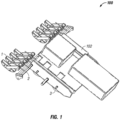
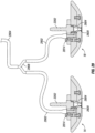
- Inspections are conducted with a robotic system 100 (e.g., an inspection robot, a robotic vehicle, etc.) which may utilize sensor sleds 1 and a sled array system 2 which enables accurate, self-aligning, and self-stabilizing contact with a surface (not shown) while also overcoming physical obstacles and maneuvering at varying or constant speeds.
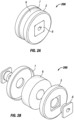
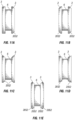
- mobile contact of the system 100 with the surface includes a magnetic wheel 3.
- a sled array system 2 is referenced herein as a payload 2 - wherein a payload 2 is an arrangement of sleds 1 with sensor mounted thereon, and wherein, in certain embodiments, an entire payload 2 can be changed out as a unit.
- payloads 2 allows for a pre-configured sensor array that provides for rapid re-configuration by swapping out the entire payload 2.
- sleds 1 and/or specific sensors on sleds 1 are changeable within a payload 2 to reconfigure the sensor array.
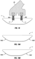
- An example sensor sled 1 includes, without limitation, one or more sensors mounted thereon such that the sensor(s) is operationally couplable to an inspection surface in contact with a bottom surface of the corresponding one of the sleds.
- the sled 1 may include a chamber or mounting structure, with a hole at the bottom of the sled 1 such that the sensor can maintain line-of-sight and/or acoustic coupling with the inspection surface.
- the sled 1 as described throughout the present disclosure is mounted on and/or operationally coupled to the inspection robot 100 such that the sensor maintains a specified alignment to the inspection surface 100 - for example a perpendicular arrangement to the inspection surface, or any other specified angle.
- a sensor mounted on a sled 1 may have a line-of-sight or other detecting arrangement to the inspection surface that is not through the sled 1 - for example a sensor may be mounted at a front or rear of a sled 1, mounted on top of a sled 1 (e.g., having a view of the inspection surface that is forward, behind, to a side, and/or oblique to the sled 1).
- a sensor may be mounted on the inspection robot 100 and/or a payload 2 - for example a camera mounted on the inspection robot 100.
- Example physical structures include industrial structures such as boilers, pipelines, tanks, ferromagnetic structures, and other structures.
- An example system 100 is configured for climbing the outside of tube walls.
- the disclosure provides a system that is capable of integrating input from sensors and sensing technology that may be placed on a robotic vehicle.
- the robotic vehicle is capable of multi-directional movement on a variety of surfaces, including flat walls, curved surfaces, ceilings, and/or floors (e.g., a tank bottom, a storage tank floor, and/or a recovery boiler floor).
- floors e.g., a tank bottom, a storage tank floor, and/or a recovery boiler floor.
- the system 100 (e.g., an inspection robot, a robotic vehicle, and/or supporting devices such as external computing devices, couplant or fluid reservoirs and delivery systems, etc.) in Fig. 1 includes the sled 1 mounted on a payload 2 to provide for an array of sensors having selectable contact (e.g., orientation, down force, sensor spacing from the surface, etc.) with an inspected surface.
- the payload 2 includes mounting posts mounted to a main body 102 of the system 100. The payload 2 thereby provides a convenient mounting position for a number of sleds 1, allowing for multiple sensors to be positioned for inspection in a single traverse of the inspected surface.
- an example sled 1 has an aperture 12, for example to provide for couplant communication (e.g., an acoustically and/or optically continuous path of couplant) between the sensor mounted on the sled 1 and a surface to be inspected, to provide for line-of-sight availability between the sensor and the surface, or the like.
- couplant communication e.g., an acoustically and/or optically continuous path of couplant
- an example system 100 includes the sled 1 held by an arm 20 that is connected to the payload 2 (e.g., a sensor array or sensor suite).
- An example system includes the sled 1 coupled to the arm 20 at a pivot point 17, allowing the sensor sled to rotate and/or tilt.
- an example payload 2 includes a biasing member 21 (e.g., a torsion spring) with another pivot point 16, which provides for a selectable down-force of the arm 20 to the surface being inspected, and for an additional degree of freedom in sled 1 movement to ensure the sled 1 orients in a desired manner to the surface.
- a biasing member 21 e.g., a torsion spring
- down-force provides for at least a partial seal between the sensor sled 1 and surface to reduce or control couplant loss (e.g., where couplant loss is an amount of couplant consumed that is beyond what is required for operations), control distance between the sensor and the surface, and/or to ensure orientation of the sensor relative to the surface.
- the arm 20 can lift in the presence of an obstacle, while traversing between surfaces, or the like, and return to the desired position after the maneuver is completed.
- an additional pivot 18 couples the arm 20 to the payload 2, allowing for an additional rolling motion.
- pivots 16, 17, 18 provide for three degrees of freedom on arm 20 motion, allowing the arm 20 to be responsive to almost any obstacle or surface shape for inspection operations.
- various features of the system 100 including one or more pivots 16, 17, 18, co-operate to provide self-alignment of the sled 1 (and thus, the sensor mounted on the sled) to the surface.
- the sled 1 self-aligns to a curved surface and/or to a surface having variability in the surface shape.
- the system is also able to collect information at multiple locations at once. This may be accomplished through the use of a sled array system.
- the sled array system allows for mounting sensor mounts, like the sleds, in fixed positions to ensure thorough coverage over varying contours.
- the sled array system allows for adjustment in spacing between sensors, adjustments of sled angle, and traveling over obstacles.
- the sled array system was designed to allow for multiplicity, allowing sensors to be added to or removed from the design, including changes in the type, quantity, and/or physical sensing arrangement of sensors.
- the sensor sleds that may be employed within the context of the present invention may house different sensors for diverse modalities useful for inspection of a structure.
- sensor sleds are able to stabilize, align, travel over obstacles, and control, reduce, or optimize couplant delivery which allows for improved sensor feedback, reduced couplant loss, reduced post-inspection clean-up, reduced down-time due to sensor re-runs or bad data, and/or faster return to service for inspected equipment.
- sled assemblies which are self-aligning to accommodate variabilities in the surface being traversed (e.g., an inspection surface) while maintaining the bottom surface of the sled (and/or a sensor or tool, e.g. where the sensor or tool protrudes through or is flush with a bottom surface of the sled) in contact with the inspection surface and the sensor or tool in a fixed orientation relative to the inspection surface.
- a sensor or tool e.g. where the sensor or tool protrudes through or is flush with a bottom surface of the sled
- each payload 2 including a sled 1 positioned between a pair of sled arms 20, with each side exterior of the sled 1 attached to one end of each of the sled arms 20 at a pivot point 17 so that the sled 1 is able to rotate around an axis that would run between the pivot points 17 on each side of the sled 1.
- the payload 2 may include one or more inspection sleds 1 being pushed ahead of the payload 2, pulled behind the payload 2, or both.
- the other end of each sled arm 20 is attached to an inspection sled mount 14 with a pivot connection 16 which allows the sled arms to rotate around an axis running through the inspection sled mount 14 between the two pivot connections 16.
- each pair of sled arms 20 can raise or lower independently from other sled arms 20, and with the corresponding sled 1.
- the inspection sled mount 14 attaches to the payload 2, for example by mounting on shaft 19.
- the inspection sled mount 14 may connect to the payload shaft 19 with a connection 18 which allows the sled 1 and corresponding arms 20 to rotate from side to side in an arc around a perpendicular to the shaft 19. Together the up and down and side to side arc, where present, allow two degrees of rotational freedom to the sled arms.
- Connection 18 is illustrated as a gimbal mount in the example of Fig.
- the gimbal mount 18 allows the sled 1 and associated arms 20 to rotate to accommodate side to side variability in the surface being traversed or obstacles on one side of the sled 1.
- the pivot points 17 between the sled arms 20 and the sled 1 allow the sled 1 to rotate (e.g., tilt in the direction of movement of the inspection robot 100) to conform to the surface being traversed and accommodate to variations or obstacles in the surface being traversed. Pivot point 17, together with the rotational freedom of the arms, provides the sled three degrees of rotational freedom relative to the inspection surface.
- the ability to conform to the surface being traversed facilitated the maintenance of a perpendicular interface between the sensor and the surface allowing for improved interaction between the sled 1 and the inspection surface. Improved interaction may include ensuring that the sensor is operationally couplable to the inspection surface.
- a biasing member e.g., torsion spring 21
- the down force is selectable by changing the torsion spring, and/or by adjusting the configuration of the torsion spring (e.g., confining or rotating the torsion spring to increase or decrease the down force).
- Analogous operations or structures to adjust the down force for other biasing members e.g., a cylindrical spring, actuator for active down force control, etc. are contemplated herein.
- the inspection robot 100 includes a tether (not shown) to provide power, couplant or other fluids, and/or communication links to the robot 100. It has been demonstrated that a tether to support at least 200 vertical feet (60,96 meters) of climbing can be created, capable of couplant delivery to multiple ultra-sonic sensors, sufficient power for the robot, and sufficient communication for real-time processing at a computing device remote from the robot. Certain aspects of the disclosure herein, such as but not limited to utilizing couplant conservation features such as sled downforce configurations, the acoustic cone, and water as a couplant, support an extended length of tether.
- couplant conservation features such as sled downforce configurations, the acoustic cone, and water as a couplant
- multiple ultra-sonic sensors can be provided with sufficient couplant through a 1/8" (3,17 mm) couplant delivery line, and/orthrough a 1 ⁇ 4" (6,35 mm) couplant delivery line to the inspection robot 100, with 1/8" (3,17 mm) final delivery lines to individual sensors.
- the inspection robot 100 is described as receiving power, couplant, and communications through a tether, any or all of these, or other aspects utilized by the inspection robot 100 (e.g., paint, marking fluid, cleaning fluid, repair solutions, etc.) may be provided through a tether or provided in situ on the inspection robot 100.
- the inspection robot 100 may utilize batteries, a fuel cell, and/or capacitors to provide power; a couplant reservoir and/or other fluid reservoir on the robot to provide fluids utilized during inspection operations, and/or wireless communication of any type for communications, and/or store data in a memory location on the robot for utilization after an inspection operation or a portion of an inspection operation.
- maintaining sleds 1 (and sensors or tools mounted thereupon) in contact and/or selectively oriented (e.g., perpendicular) to a surface being traversed provides for: reduced noise, reduced lost-data periods, fewer false positives, and/or improved quality of sensing; and/or improved efficacy of tools associated with the sled (less time to complete a repair, cleaning, or marking operation; lower utilization of associated fluids therewith; improved confidence of a successful repair, cleaning, or marking operation, etc.).
- maintaining sleds 1 in contacts and/or selectively oriented to the surface being traversed provides for reduced losses of couplant during inspection operations.
- the combination of the pivot points 16, 17, 18) and torsion spring 21 act together to position the sled 1 perpendicular to the surface being traversed.
- the biasing force of the spring 21 may act to extend the sled arms 20 downward and away from the payload shaft 19 and inspection sled mount 14, pushing the sled 1 toward the inspection surface.
- the torsion spring 21 may be passive, applying a constant downward pressure, or the torsion spring 21 or other biasing member may be active, allowing the downward pressure to be varied.
- an active torsion spring 21 might be responsive to a command to relax the spring tension, reducing downward pressure and/or to actively pull the sled 1 up, when the sled 1 encounters an obstacle, allowing the sled 1 to more easily move over the obstacle.
- the active torsion spring 21 may then be responsive to a command to restore tension, increasing downward pressure, once the obstacle is cleared to maintain the close contact between the sled 1 and the surface.
- the use of an active spring may enable changing the angle of a sensor or tool relative to the surface being traversed during a traverse. Design considerations with respect to the surfaces being inspected may be used to design the active control system.
- spring 21 may be a combination of passive and active biasing members.
- the downward pressure applied by the torsion spring 21 may be supplemented by a spring within the sled 1 further pushing a sensor or tool toward the surface.
- the downward pressure may be supplemented by one or more magnets in/on the sled 1 pulling the sled 1 toward the surface being traversed.
- the one or more magnets may be passive magnets that are constantly pulling the sled 1 toward the surface being traversed, facilitating a constant distance between the sled 1 and the surface.
- the one or magnets may be active magnets where the magnet field strength is controlled based on sensed orientation and/or distance of the sled 1 relative to the inspection surface. In an illustrative and non-limiting example, as the sled 1 lifts up from the surface to clear an obstacle and it starts to roll, the strength of the magnet may be increased to correct the orientation of the sled 1 and draw it back toward the surface.
- connection between each sled 1 and the sled arms 20 may constitute a simple pin or other quick release connect/disconnect attachment.
- the quick release connection at the pivot points 17 may facilitate attaching and detaching sleds 1 enabling a user to easily change the type of inspection sled attached, swapping sensors, types of sensors, tools, and the like.
- the location of the pivot point accommodations 9 on the sled 1 may be selected to accommodate conflicting goals such as sled 1 stability and clearance of surface obstacles. Positioning the pivot point accommodations 9 behind the center of sled in the longitudinal direction of travel may facilitate clearing obstacles on the surface being traversed. Positioning the pivot point accommodation 9 forward of the center may make it more difficult for the sled 1 to invert or flip to a position where it cannot return to a proper inspection operation position. It may be desirable to alter the connection location of the sled arms 20 to the pivot point accommodations 9 (thereby defining the pivot point 17) depending on the direction of travel.
- pivot point 17 selection can occur before an inspection operation, and/or be selectable during an inspection operation (e.g., arms 20 having an actuator to engage a selected one of the pivot points 9, such as extending pegs or other actuated elements, thereby selecting the pivot point 17).
- the degree of rotation allowed by the pivot points 17 may be adjustable. This may be done using mechanical means such as a physical pin or lock.
- the connection between the sled 1 and the sled arms 20 may include a spring 1702 that biases the pivot points 17 to tend to pivot in one direction or another.
- the spring 1702 may be passive, with the selection of the spring based on the desired strength of the bias, and the installation of the spring 1702 may be such as to preferentially push the front or the back of the sled 1 down.
- the spring 1702 may be active and the strength and preferential pivot may be varied based on direction of travel, presence of obstacles, desired pivoting responsiveness of the sled 1 to the presence of an obstacle or variation in the inspection surface, and the like.
- opposing springs or biasing members may be utilized to bias the sled 1 back to a selected position (e.g., neutral/flat on the surface, tilted forward, tilted rearward, etc.). Where the sled 1 is biased in a given direction (e.g., forward or rearward), the sled 1 may nevertheless operate in a neutral position during inspection operations, for example due to the down force from the arm 20 on the sled 1.
- An example sled 1, for example as shown in Fig. 18 includes more than one pivot point 17, for example utilizing springs 402 to couple to the sled arm 20.
- the two pivot points 17 provide additional clearance for the sled 1 to clear obstacles.
- both springs 402 may be active, for example allowing some rotation of each pivot simultaneously, and/or a lifting of the entire sled.
- springs 402 may be selectively locked - for example before inspection operations and/or actively controlled during inspection operations. Additionally or alternatively, selection of pivot position, spring force and/or ease of pivoting at each pivot may be selectively controlled - for example before inspection operations and/or actively controlled during inspection operations (e.g., using a controller 802).
- springs 402 is a non-limiting example of simultaneous multiple pivot points, and leaf springs, electromagnets, torsion springs, or other flexible pivot enabling structures are contemplated herein.
- the spring tension or pivot control may be selected based on the uniformity of the surface to be traversed.
- the spring tension may be varied between the front and rear pivot points depending on the direction of travel of the sled 1.
- the rear spring (relative to the direction of travel) might be locked and the front spring active when traveling forward to better enable obstacle accommodation.
- the active and locked springs 402 may be reversed such that what was the rear spring 402 may now be active and what was the front spring 402 may now be locked, again to accommodate obstacles encountered in the new direction of travel.
- the bottom surface of the sled 1 may be shaped, as shown in Figs. 19A, 19B , with one or more ramps 1902 to facilitate the sled 1 moving over obstacles encountered along the direction of travel.
- the shape and slope of each ramp 1902 may be designed to accommodate conflicting goals such as sled 1 stability, speed of travel, and the size of the obstacle the sled 1 is designed to accommodate.
- a steep ramp angle might be better for accommodating large obstacles but may be required to move more slowly to maintain stability and a good interaction with the surface.
- the slope of the ramp 1902 may be selected based on the surface to be traversed and expected obstacles. If the sled 1 is interacting with the surface in only one direction, the sled 1 may be designed with only one ramp 1902.
- the sled 1 may be designed with two ramps 1902, e.g., a forward ramp and a rearward ramp, such that the sled 1 leads with a ramp 1902 in each direction of travel.
- the front and rear ramps 1902 may have different angles and/or different total height values. While the ramps 1902 depicted in Figs. 19A and 19B are linear ramps, a ramp 1902 may have any shape, including a curved shape, a concave shape, a convex shape, and/or combinations thereof.
- ramp angle The selection of the ramp angle, total ramp height, and bottom surface shape is readily determinable to one of skill in the art having the benefit of the disclosure herein and information ordinarily available when contemplating a system.
- Certain considerations for determining the ramp angle, ramp total height, and bottom surface shape include considerations of manufacturability, obstacle geometries likely to be encountered, obstacle materials likely to be encountered, materials utilized in the sled 1 and/or ramp 1902, motive power available to the inspection robot 100, the desired response to encountering obstacles of a given size and shape (e.g., whether it is acceptable to stop operations and re-configure the inspection operations for a certain obstacle, or whether maximum obstacle traversal capability is desired), and/or likely impact speed with obstacles for a sled.
- the bottom surface 2002 of the sled 1 may be contoured or curved to accommodate a known texture or shape of the surface being traversed, for example such that the sled 1 will tend to remain in a desired orientation (e.g., perpendicular) with the inspection surface as the sled 1 is moved.
- the bottom surface 2002 of the sled 1 may be shaped to reduce rotation, horizontal translation and shifting, and/or yaw or rotation of the sled 1 from side to side as it traverses the inspection surface. Referencing Fig.
- the bottom surface 2002 of the sled 1 may be convex for moving along a rounded surface, on the inside of a pipe or tube, and/or along a groove in a surface.
- the bottom surface 2002 of the sled 1 may be concave for the exterior of a rounded surface, such as riding on an outer wall of a pipe or tube, along a rounded surface, and/or along a ridge in a surface.
- the radius of curvature of the bottom surface 2002 of the sled 1 may be selected to facilitate alignment given the curvature of the surface to be inspected.
- the bottom surface 2002 of the sled 1 may be shaped to facilitate maintaining a constant distance between sensors or tools in the sled 1 and the inspection surface being traversed.
- at least a portion the bottom of the sled 1 may be flexible such that the bottom of the sled 1 may comply to the shape of the surface being traversed. This flexibility may facilitate traversing surfaces that change curvature over the length of the surface without the adjustments to the sled 1.
- a chamfer or curve on the bottom surface 2002 of a sled 1 tends to guide the sled 1 to a portion of the variable curvature matching the curvature of the bottom surface 2002. Accordingly, the curved bottom surface 2002 supports maintaining a selected orientation of the sled 1 to the inspection surface.
- the bottom surface 2002 of the sled 1 is not curved, and one or more pivots 16, 17, 18 combined with the down force from the arms 20 combine to support maintaining a selected orientation of the sled 1 to the inspection surface.
- the bottom of the sled 1 may be flexible such that the curvature may adapt to the curvature of the surface being traversed.
- the material on the bottom of the sled 1 may be chosen to prevent wear on the sled 1, reduce friction between the sled 1 and the surface being traversed, or a combination of both.
- Materials for the bottom of the sled may include materials such as plastic, metal, or a combination thereof.
- Materials for the bottom of the sled may include an epoxy coat, a replaceable layer of polytetrafluoroethylene (e.g., Teflon, acetyl (e.g., Delrin ® acetyl resin), ultrafine molecular weight polyethylene (PMW), and the like.
- polytetrafluoroethylene e.g., Teflon, acetyl (e.g., Delrin ® acetyl resin)
- PMW ultrafine molecular weight polyethylene
- the material on the bottom of the sled 1 may be removable layer such as a sacrificial film 2012 (or layer, and/or removable layer) that is applied to the bottom of the sled 1 and then lifted off and replaced at selected intervals, before each inspection operation, and/or when the film 2012 or bottom of the sled begin to show signs of wear or an increase in friction.
- An example sled 1 includes an attachment mechanism 2104, such as a clip, to hold the sacrificial film 2012 in place. Referencing Fig.
- an example sled 1 includes a recess 2306 in the bottom surface of the sled to retain the sacrificial film 2012 and allow the sacrificial film 2012 to have a selected spatial orientation between the inspection contact side (e.g., the side of the sacrificial film 2012 exposed to the inspection surface) with the bottom surface 2002 of the sled 1 (e.g., flush with the bottom, extending slightly past the bottom, etc.).
- the removable layer may include a thickness that provides a selected spatial orientation between an inspection contact side in contact with the inspection surface and the bottom surface of the sled.
- the sacrificial film 2012 includes an adhesive, for example with an adhesive backing to the layer, and/or may be applied as an adhesive (e.g., an epoxy layer or coating that is refreshed or reapplied from time to time).
- An example sacrificial film 2012 includes a hole therethrough, for example allowing for visual and/or couplant contact between a sensor 2202 attached to the sled 1 and the inspection surface. The hole may be positioned over the sensor 2202, and/or may accommodate the sensor 2202 to extend through the sacrificial film 2012, and/or may be aligned with a hole 2016 (e.g., Fig. 21 ) or aperture 12 (e.g., Fig. 3B ) in the sled bottom.
- a hole 2016 e.g., Fig. 21
- aperture 12 e.g., Fig. 3B
- an example sled 1 includes an upper portion 2402 and a replaceable lower portion 2404 having a bottom surface.
- the lower portion 2404 may be designed to allow the bottom surface and shape to be changed to accommodate the specific surface to be traversed without having to disturb or change the upper portion 2402. Accordingly, where sensors or tools engage the upper portion 2402, the lower portion 2404 can be rapidly changed out to configure the sled 1 to the inspection surface, without disturbing sensor connections and/or coupling to the arms 20.
- the lower portion 2404 may additionally or alternatively be configured to accommodate a sacrificial layer 2012, including potentially with a recess 2306.
- An example sled 1 includes a lower portion 2404 designed to be easily replaced by lining up the upper portion 2402 and the lower portion 2404 at a pivot point 2406, and then rotating the pieces to align the two portions.
- the sensor, installation sleeve, cone tip, or other portion protruding through aperture 12 forms the pivot point 2406.
- One or more slots 2408 and key 2410 interfaces or the like may hold the two portions together.
- the ability to quickly swap the lower portion 2404 may facilitate changing the bottom surface of the sled 1 to improve or optimize the bottom surface of the sled 1 for the surface to be traversed.
- the lower portion may be selected based on bottom surface shape, ramp angle, or ramp total height value.
- the lower portion may be selected from a multiplicity of pre-configured replaceable lower portions in response to observed parameters of the inspection surface after arrival to an inspection site.
- the lower portion 2404 may include a simple composition, such as a wholly integrated part of a single material, and/or may be manufactured on-site (e.g., in a 3-D printing operation) such as for a replacement part and/or in response to observed parameters of the inspection surface after arrival to an inspection site.
- Improvement and/or optimization may include: providing a low friction material as the bottom surface to facilitate the sled 1 gliding over the surface being traversed, having a hardened bottom surface of the sled 1 if the surface to be traversed is abrasive, producing the lower portion 2404 as a wear material or low-cost replacement part, and the like.
- the replacement lower portion 2404 may allow for quick replacement of the bottom surface when there is wear or damage on the bottom surface of the sled 1.
- a user may alter a shape/curvature of the bottom of the sled, a slope or length of a ramp, the number of ramps, and the like.
- a sled 1 may have a chamber 2624 sized to accommodate a sensor 2202, and/or into which a sensor 2202 may be inserted.
- the chamber 2624 may have chamfers 2628 on at least one side of the chamber to facilitate ease of insertion and proper alignment of the sensor 2202 in the chamber 2624.
- An example sled 1 includes a holding clamp 2630 that accommodates the sensor 2202 to pass therethrough, and is attached to the sled 1 by a mechanical device 2632 such as a screw or the like.
- An example sled 1 includes stops 2634 at the bottom of the chamber 2624, for example to ensure a fixed distance between the sensor 2202 and bottom surface of the sled and/or the inspection surface, and/or to ensure a specific orientation of the sensor 2202 to the bottom surface of the sled and/or the inspection surface.
- an example sled 1 includes a sensor installation sleeve 2704, which may be positioned, at least partially, within the chamber.
- the example sensor installation sleeve 2704 may be formed from a compliant material such as neoprene, rubber, an elastomeric material, and the like, and in certain embodiments may be an insert into a chamber 2624, a wrapper material on the sensor 2202, and/or formed by the substrate of the sled 1 itself (e.g., by selecting the size and shape of the chamber 2624 and the material of the sled 1 at least in the area of the chamber 2624).
- An example sleeve 2704 includes an opening 2 sized to receive a sensor 2202 and/or a tool (e.g., marking, cleaning, repair, and/or spray tool).
- the sensor installation sleeve 2704 flexes to accommodate the sensor 2202 as the sensor 2202 is inserted.
- a sleeve 2704 may include a material wrapping the sensor 2202 and slightly oversized for the chamber 2624, where the sleeve compresses through the hole into the chamber 2624, and expands slightly when released, thereby securing the sensor 2202 into the sled 1.
- an installation tab 2716 is formed by relief slots 2714. The tab 2716 flexes to engage the sensor 2202, easing the change of the sensor 2202 while securing the sensor 2202 in the correct position once inserted into the sled 1.
- a variety of sensor and tool types and sizes may be swapped in and out of a single sled 1 using the same sensor installation sleeve 2704.
- the opening of the chamber 2624 may include the chamfers 2628 to facilitate insertion, release, and positioning of the sensor 2202, and/or the tab 2716 to provide additional compliance to facilitate insertion, release, and positioning of the sensor 2202 and/or to accommodate varying sizes of sensors 2202.
- a sensor 2202 includes any hardware of interest for inserting or coupling to a sled 1, including at least: a sensor, a sensor housing or engagement structure, a tool (e.g., a sprayer, marker, fluid jet, etc.), and/or a tool housing or engagement structure.
- an acoustic cone 2804 is depicted.
- the acoustic cone 2804 includes a sensor interface 2808, for example to couple an acoustic sensor with the cone 2804.
- the example acoustic cone 2804 includes a couplant interface 2814, with a fluid chamber 2818 coupling the couplant interface 2814 to the cone fluid chamber 2810.
- the cone tip 2820 of the acoustic cone 2804 is kept in contact with the inspection surface, and/or kept at a predetermined distance from the inspection surface while the acoustic sensor is mounted at the opposite end of the acoustic cone 2804 (e.g., at sensor interface 2808).
- the cone tip 2820 may define a couplant exit opening between the couplant chamber and the inspection surface.
- the couplant exit opening may be flush with the bottom surface or extend through the bottom of the sled. Accordingly, a delay line (e.g., acoustic or vibration coupling of a fixed effective length) between the sensor and the inspection surface is kept at a predetermined distance throughout inspection operations.
- the acoustic cone 2804 couples to the sled 1 in a predetermined arrangement, allowing for replacement of the sensor, and/or swapping of a sled 1 without having to recalibrate acoustic and/or ultra-sonic measurements.
- the volume between the sensor and the inspection surface is maintained with couplant, providing a consistent delay line between the sensor and the inspection surface.
- Example and non-limiting couplant fluids include alcohol, a dye penetrant, an oil-based liquid, an ultra-sonic gel, or the like.
- An example couplant fluid includes particle sizes not greater than 0.159 centimeters (1/16 of an inch).
- the couplant is filtered before delivery to the sled 1.
- the couplant includes water, which is low cost, low viscosity, easy to pump and compatible with a variety of pump types, and may provide lower resistance to the movement of the inspection sled over the surface than gels.
- water may be an undesirable couplant, and any type of couplant fluid may be provided.
- An example acoustic cone 2804 provides a number of features to prevent or remove air bubbles in the cone fluid chamber 2810.
- An example acoustic cone 2804 includes entry of the fluid chamber 2818 into a vertically upper portion of the cone fluid chamber 2810 (e.g., as the inspection robot 100 is positioned on the inspection surface, and/or in an intended orientation of the inspection robot 100 on the inspection surface, which may toward the front of the robot where the robot is ascending vertically), which tends to drive air bubbles out of the cone fluid chamber 2810.
- the utilization of the acoustic cone 2804, and the ability to minimize sensor coupling and de-coupling events contributes to a reduction in leaks and air bubble formation.
- a controller 802 periodically and/or in response to detection of a potential air bubble (e.g., due to an anomalous sensor reading) commands a debubbling operation, for example increasing a flow rate of couplant through the cone 2804.
- the arrangements described throughout the present disclosure provide for sufficient couplant delivery to be in the range of 0.06 to 0.08 gallons (0,23 to 0,30 liters) per minute using a 1/8" (3,17 mm) fluid delivery line to the cone 2804.
- nominal couplant flow and pressure is sufficient to prevent the formation of air bubbles in the acoustic cone 2804.
- individual tubing 2902 may be connected to each couplant interface 2814.
- the individual tubing 2902 may be connected directly to a sled 1A, 1B rather than the individual tubing 2902, for example with sled 1A, 1B plumbing permanently coupled to the couplant interface 2814.
- Two or more individual tubing 2902 sections may then be joined together in a tubing junction 2908 with a single tube 2904 leaving the junction. In this way, a number of individual tubes 2902 may be reduced to a single tube 2904 that may be easily connected/disconnected from the source of the couplant.
- an entire payload 2 may include a single couplant interface, for example to the inspection robot 100.
- the inspection robot 100 may include a couplant reservoir and/or a delivery pump thereupon, and/or the inspection robot 100 may be connected to an external couplant source.
- an entire payload 2 can be changed out with a single couplant interface change, and without any of the cone couplant interfaces and/or sensor couplant interface being disconnected.
- the integration of the sensor 2202, acoustic cone 2804, and cone tip 2820 is designed to maintain a constant distance between the surface being measured and the acoustic sensor 2202. The constant distance facilitates in the interpretation of the data recorded by the acoustic sensor 2202.
- the distance between the surface being measured and the acoustic sensor 2202 may be described as the "delay line.”
- Certain embodiments include an apparatus for providing acoustic coupling between a carriage (or sled) mounted sensor and an inspection surface.
- Example and non-limiting structures to provide acoustic coupling between a carriage mounted sensor and an inspection surface include an acoustic (e.g., an ultra-sonic) sensor mounted on a sled 1, the sled 1 mounted on a payload 2, and the payload 2 coupled to an inspection robot.
- An example apparatus further includes providing the sled 1 with a number of degrees of freedom of motion, such that the sled 1 can maintain a selected orientation with the inspection surface - including a perpendicular orientation and/or a selected angle of orientation.
- the sled 1 is configured to track the surface, for example utilizing a shaped bottom of the sled 1 to match a shape of the inspection surface or a portion of the inspection surface, and/or the sled 1 having an orientation such that, when the bottom surface of the sled 1 is positioned against the inspection surface, the sensor maintains a selected angle with respect to the inspection surface.
- an apparatus for providing acoustic coupling between a carriage mounted sensor and an inspection surface include utilization of a fixed-distance structure that ensures a consistent distance between the sensor and the inspection surface.
- the sensor may be mounted on a cone, wherein an end of the cone touches the inspection surface and/or is maintained in a fixed position relative to the inspection surface, and the sensor mounted on the cone thereby is provided at a fixed distance from the inspection surface.
- the sensor may be mounted on the cone, and the cone mounted on the sled 1, such that a change-out of the sled 1 can be performed to change out the sensor, without engaging or disengaging the sensor from the cone.
- the cone may be configured such that couplant provided to the cone results in a filled couplant chamber between a transducer of the sensor and the inspection surface.
- a couplant entry position for the cone is provided at a vertically upper position of the cone, between the cone tip portion and the sensor mounting end, in an orientation of the inspection robot as it is positioned on the surface, such that couplant flow through the cone tends to prevent bubble formation in the acoustic path between the sensor and the inspection surface.
- the couplant flow to the cone is adjustable, and is capable, for example, to be increased in response to a determination that a bubble may have formed within the cone and/or within the acoustic path between the sensor and the inspection surface.
- the sled 1 is capable of being lifted, for example with an actuator that lifts an arm 20, and/or that lifts a payload 2, such that a free fluid path for couplant and attendant bubbles to exit the cone and/or the acoustic path is provided.
- operations to eliminate bubbles in the cone and/or acoustic path are performed periodically, episodically (e.g., after a given inspection distance is completed, at the beginning of an inspection run, after an inspection robot pauses for any reason, etc.), and/or in response to an active determination that a bubble may be present in the cone and/or the acoustic path.
- An example apparatus provides for low or reduced fluid loss of couplant during inspection operations.
- Example and non-limiting structures to provide for low or reduced fluid loss include providing for a limited flow path of couplant out of the inspection robot system - for example utilizing a cone having a smaller exit couplant cross-sectional area than a cross-sectional area of a couplant chamber within the cone.
- an apparatus for low or reduced fluid loss of couplant includes structures to provide for a selected down force on a sled 1 which the sensor is mounted on, on an arm 20 carrying a sled 1 which the sensor is mounted on, and/or on a payload 2 which the sled 1 is mounted on.
- an apparatus providing for low or reduced fluid loss of couplant includes a selected down force on a cone providing for couplant connectivity between the sensor and the inspection surface - for example a leaf spring or other biasing member within the sled 1 providing for a selected down force directly to the cone.
- low or reduced fluid loss includes providing for an overall fluid flow of between 0.12 to 0.16 gallons (0,45 to 0,6 liters) per minute to the inspection robot to support at least 10 ultra-sonic sensors.
- low or reduced fluid loss includes providing for an overall fluid flow of less than 50 feet (15,24 meters) per minute, less than 100 feet (30,48 meters) per minute, and less than 200 feet per minute fluid velocity in a tubing line feeding couplant to the inspection robot.
- low or reduced fluid loss includes providing sufficient couplant through a %" (6,35 mm) tubing line to feed couplant to at least 6, at least 8, at least 10, at least 12, or at least 16 ultra-sonic sensors to a vertical height of at least 25 feet, at least 50 feet (15,24 meters), at least 100 feet (30,48 meters), at least 150 feet, or at least 200 feet (60,96 meters).
- An example apparatus includes a %" (6,35 mm) feed line to the inspection robot and/or to the payload 2, and a 1/8" (3,17 mm) feed line to individual sleds 1 and/or sensors (or acoustic cones associated with the sensors). In certain embodiments, larger and/or smaller diameter feed and individual fluid lines are provided.
- an example procedure 3000 to provide acoustic coupling between a sensor and an inspection surface is depicted schematically.
- the example procedure 3000 includes an operation 3002 to provide a fixed acoustic path between the sensor and the inspection surface.
- the example procedure 3000 further includes an operation 3004 to fill the acoustic path with a couplant.
- the example procedure 3000 further includes an operation 3006 to provide for a selected orientation between the sensor and the inspection surface.
- certain operations of the procedure 3000 are performed iteratively throughout inspection operations - for example operations 3006 may include maintaining the orientation throughout inspection operations - such as providing the sensor on a sled having a bottom surface and/or maneuverability to passively or actively self-align to the inspection surface, and/or to return to alignment after a disturbance such as traversal of an obstacle.
- operations 3004 include providing a couplant flow to keep the acoustic path between the sensor and the inspection surface filled with couplant, and/or adjusting the couplant flow during inspection operations.
- Certain operations of procedure 3000 may be performed by a controller 802 during inspection operations.
- an example procedure 3100 to ensure acoustic engagement between a sensor and an inspection surface is depicted schematically.
- the example procedure 3100 includes an operation 3102 to provide an acoustic coupling chamber between the sensor and the inspection surface.
- Example and non-limiting operations 3102 include providing the acoustic coupling chamber with an arrangement that tends to reduce bubble formation within the acoustic path between the sensor and the inspection surface.
- the example procedure 3100 further includes an operation 3104 to determine that the sensor should be re-coupled to the inspection surface.
- Example and non-limiting operations 3104 include determining that a time has elapsed since a last re-coupling operation, determining that an event has occurred and performing a re-coupling operation in response to the event, and/or actively determining that the acoustic path has been interrupted.
- Example and non-limiting events include a pausing of the inspection robot, a beginning of inspection operations and/or completion of a selected portion of inspection operations, and/or an interruption of couplant flow to the inspection robot.
- Example and non-limiting operation to actively determine that the acoustic path has been interrupted include an observation of a bubble (e.g., in an acoustic cone), an indication that couplant may have exited the acoustic path (e.g., the sled 1 has lifted either for an obstacle or for another operation, observation of an empty cone, etc.), and/or an indication that a sensor reading is off-nominal (e.g., signal seems to have been lost, anomalous reading has occurred, etc.).
- the example procedure 3100 further includes an operation 3106 to re-couple the sensor to the inspection surface.
- Example and non-limiting operations 3106 include resuming and/or increasing a couplant flow rate, and/or briefly raising a sled, sled arm, and/or payload from the inspection surface.
- the procedure 3100 and/or portions thereof may be repeated iteratively during inspection operations. Certain operations of procedure 3100 may be performed by a controller 802 during inspection operations.
- An example procedure 3200 to provide low fluid loss (and/or fluid consumption) between an acoustic sensor and an inspection surface is depicted schematically.
- An example procedure 3200 includes an operation 3202 to provide for a low exit cross-sectional area for couplant from an acoustic path between the sensor and the inspection surface - including at least providing an exit from a couplant chamber formed by a cone as the exit cross-sectional area, and/or providing an exit cross-sectional area that is in a selected proximity to, and/or in contact with, the inspection surface.
- the example procedure 3200 further includes an operation 3204 to provide a selected down force to a sled having the sensor mounted thereon, and/or to a couplant chamber.
- the example procedure 3200 includes an operation 3206 to determine if fluid loss for the couplant is excessive (e.g., as measured by replacement couplant flow provided to an inspection robot, and/or by observed couplant loss), and an operation 3208 to increase a down force and/or reduce a couplant exit cross-sectional area from a couplant chamber.
- an inspection robot includes a configurable down force, such as: an active magnet strength control; a biasing member force adjustment (e.g., increasing confinement of a spring to increase down force); sliding of a weight in a manner to adjust down force on the sled and/or cone; combinations of these; or the like.
- an exit cross-sectional are for couplant is adjustable - for example an iris actuator (not shown), gate valve, or cross-sectional area adjustment is provided.
- cross-sectional area is related to the offset distance of the couplant chamber exit (e.g., cone tip) from the inspection surface, whereby a reduction of the selected offset distance of the couplant chamber exit to the inspection surface reduces the effective exit flow area of the couplant chamber.
- Example operations to adjust the selected offset distance include lowering the couplant chamber within the sled and/or increasing a down force on the sled and/or couplant chamber. Certain operations of procedure 3200 may be performed by a controller 802 during inspection operations.
- an example system includes a wheel 200 design that enables modularity, adhesion to the structure's surface, and obstacle traversing.
- a splined hub, wheel size, and the use of magnets allow the system to be effective on many different surfaces.
- the wheel 200 includes a splined hub 8.
- the wheel 200 permits a robotic vehicle 100 to climb on walls, ceilings, and other ferromagnetic surfaces. As shown in the embodiment depicted in Figs. 2A and 2B , this may be accomplished by embedding magnets 6 in a ferromagnetic enclosure 3 and/or an electrically conductive enclosure to protect the magnet 6, improve alignment, and allow for ease of assembly.
- the magnet 6 may be a permanent magnet and/or a controllable electromagnet, and may further include a rare earth magnet.
- the ferromagnetic enclosure 3 protects the magnet 6 from directly impacting the inspected surface, reduces impacts and damage to the magnet 6, and reduces wear on the surface and the magnet 6.
- the ferromagnetic and/or electrical conductivity of the enclosure 3 reduces magnetic field lines in not-useful directions (e.g., into the housing 102, electrical lines or features that may be present near the inspected surface, etc.) and guides the magnetic field lines to the inspected surface.
- the enclosure 3 may not be ferromagnetic or conductive, and/or the enclosure 3 may be at least partially covered by a further material (e.g., molded plastic, a coating, paint, etc.), for example to protect the inspected surface from damage, to protect the enclosure 3 from wear, for aesthetic reasons, or for any other reason.
- the magnet 6 is not present, and the system 100 stays in contact with the surface in another manner (e.g., surface tension adhesion, gravity such as on a horizontal or slightly inclined inspection surface, movement along a track fixed to the surface, or the like). Any arrangements of an inspection surface, including vertical surfaces, overhang or upside-down surfaces, curved surfaces, and combinations of these, are contemplated herein.
- the wheel 200 includes a channel 7 formed between enclosures 3, for example at the center of the wheel 200.
- the channel 7 provides for self-alignment on surfaces such as tubes or pipes.
- the enclosures 300 include one or more chamfered edges or surfaces (e.g., the outer surface in the example of Fig. 3 ), for example to improve contact with a rough or curved surface, and/or to provide for a selected surface contact area to avoid damage to the surface and/or the wheel 200.
- the flat face along the rim also allows for adhesion and predictable movement on flat surfaces.
- the wheel 200 may be connected to the shaft using a splined hub 8.
- This design makes the wheel modular and also prevents it from binding due to corrosion.
- the splined hub 8 transfers the driving force from the shaft to the wheel.
- An example wheel 200 includes a magnetic aspect (e.g., magnet 6) capable to hold the robot on the wall, and accept a driving force to propel the robot, the magnet 6 positioned between conductive and/or ferromagnetic plates or enclosures, a channel 7 formed by the enclosures or plates, one or more chamfered and/or shaped edges, and/or a splined hub attachment to a shaft upon which the wheel is mounted.
- the robotic vehicle may utilize a magnet-based wheel design that enables the vehicle to attach itself to and operate on ferromagnetic surfaces, including vertical and inverted surfaces (e.g., walls and ceilings).
- the wheel design may comprise a cylindrical magnet 6 mounted between two wheel enclosures 3 with a splined hub 8 design for motor torque transfer, where the outer diameter of the two enclosures 3 is greater than the outer diameter of the magnet 6.
- the material of the magnet 6 may include a rare earth material (e.g., neodymium, yttrium-cobalt, samarium-cobalt, etc.), which may be expensive to produce, handle, and/or may be highly subject to damage or corrosion. Additionally, any permanent magnet material may have a shorter service life if exposed to direct shocks or impacts.
- a rare earth material e.g., neodymium, yttrium-cobalt, samarium-cobalt, etc.
- the channel 7 may also be utilized to assist in guiding the robotic vehicle along a feature of an inspection surface 500 (e.g., reference Fig. 5 ), such as where the channel 7 is aligned along the top of a rounded surface (e.g., pipe, or other raised feature) that the wheel uses to guide the direction of travel.
- the wheel enclosures 3 may also have guiding features 2052 (reference Figs. 11A to 11E ), such as grooves, concave or convex curvature, chamfers on the inner and/or outer edges, and the like. Referencing Fig.
- an example guiding feature 2052 includes a chamfer on an outer edge of one or both enclosures 3, for example providing self-alignment of the wheels along a surface feature, such as between raised features, on top of raised features, between two pipes 502 (which may be adjacent pipes or spaced pipes), and/or a curvature of a tube, pipe, or tank (e.g., when the inspection robot 100 traverses the interior of a pipe 502).
- a chamfer on the outer edge of the outside enclosure may enable the wheel to more easily seat next to and track along a pipe 502 that is located outside the wheel.
- having chamfers on both edges may enable the wheel to track with greater stability between two pipes 502. Referencing Fig.
- guiding features 2052 are depicted as chamfers on both sides of the wheel enclosures 3 - for example allowing the inspection robot 100 to traverse between pipes 502; on top of a single pipe 502 or on top of a span of pipes 502; along the exterior of a pipe, tube, or tank; and/or along the interior of a pipe, tube, or tank.
- guiding features 2052 are depicted as chamfers on the interior channel 7 side of the enclosures 3, for example allowing the wheel to self-align on top of a single pipe or other feature. Referencing Fig.
- guiding features 2052 are depicted as a concave curved surface, for example sized to match a pipe or other feature to be traversed by the wheel.
- guiding features 2052 are depicted as a concave curved surface formed on an interior of the channel 7, with chamfers 2052 on the exterior of the enclosure 3 - for example allowing the wheel to self-align on a single pipe or feature on the interior of the enclosure, and/or to align between pipes on the exterior of the enclosure.
- guiding features 2052 may be used to accommodate the different surface characteristics to which the robotic vehicle may be applied.
- combinations of features e.g., reference Fig. 11E
- chamfer angles, radius of curvature, vertical depth of chamfers or curves, and horizontal widths of chamfers or curves are selectable to accommodate the sizing of the objects to be traversed during inspection operations.
- the down force provided by the magnet 6 combined with the shaping of the enclosure 3 guiding features 2052 combine to provide for self-alignment of the inspection robot 100 on the surface 500, and additionally provide for protection of the magnet 6 from exposure to shock, impacts, and/or materials that may be present on the inspection surface.
- the magnet 6 may be shaped - for example with curvature (reference Fig. 11D ), to better conform to the inspection surface 500 and/or prevent impact or contact of the magnet 6 with the surface.
- guiding features may be selectable for the inspection surface - for example multiple enclosures 3 (and/or multiple wheel assemblies including the magnet 6 and enclosure 3) may be present for an inspection operation, and a suitable one of the multiple enclosures 3 provided according to the curvature of surfaces present, the spacing of pipes, the presence of obstacles, or the like.
- an enclosure 3 may have an outer layer (e.g., a removable layer - not shown) - for example a snap on, slide over, coupled with set screws, or other coupling mechanism for the outer layer, such that just an outer portion of the enclosure is changeable to provide the guiding features.
- the outer layer may be a non-ferrous material (e.g., making installation and changes of the outer layer more convenient in the presence to the magnet 6, which may complicate quick changes of a fully ferromagnetic enclosure 3), such as a plastic, elastomeric material, aluminum, or the like.
- the outer layer may be a 3-D printable material (e.g., plastics, ceramics, or any other 3-D printable material) where the outer layer can be constructed at an inspection location after the environment of the inspection surface 500 is determined.
- An example includes the controller 802 (e.g., reference Fig.
- the controller 802 structured to accept inspection parameters (e.g., pipe spacing, pipe sizes, tank dimensions, etc.), and to provide a command to a 3-D printer responsive to the command to provide an outer layer configured for the inspection surface 500.
- the controller 802 further accepts an input for the wheel definition (e.g., where selectable wheel sizes, clearance requirements for the inspection robot 100, or other parameters not necessarily defined by the inspection surface 500), and further provides the command to the 3-D printer, to provide an outer layer configured for the inspection surface 500 and the wheel definition.
- An example splined hub 8 design of the wheel assembly may enable modular re-configuration of the wheel, enabling each component to be easily switched out to accommodate different operating environments (e.g., ferromagnetic surfaces with different permeability, different physical characteristics of the surface, and the like).
- enclosures with different guiding features may be exchanged to accommodate different surface features, such as where one wheel configuration works well for a first surface characteristic (e.g., a wall with tightly spaced small pipes) and a second wheel configuration works well for a second surface characteristic (e.g., a wall with large pipes).
- the magnet 6 may also be exchanged to adjust the magnetic strength available between the wheel assembly and the surface, such as to accommodate different dimensional characteristics of the surface (e.g., features that prevent close proximity between the magnet 6 and a surface ferromagnetic material), different permeability of the surface material, and the like.
- one or both enclosures 3 may be made of ferromagnetic material, such as to direct the flux lines of the magnet toward a surface upon which the robotic vehicle is riding, to direct the flux lines of the magnet away from other components of the robotic vehicle, and the like, enabling the modular wheel configuration to be further configurable for different ferromagnetic environments and applications.
- the present disclosure provides for robotic vehicles that include a sensor sled components, permitting evaluation of particular attributes of the structure.
- the sled 1 may hold the sensor that can perform inspection of the structure.
- the sensor may be perpendicular to the surface being inspected and, in some embodiments, may have a set distance from the surface to protect it from being damaged. In other embodiments, the distance from the surface to the sensor may be adjusted to accommodate the technical requirements of the sensor being utilized.
- a couplant retaining column may be added at the sensor outlet to retain couplant depending on the type of sensor being used.
- an opening 12 may be provided at a bottom of the sled 1 to allow an installed sensor to operatively communicate with an inspection surface.
- the sleds of the present disclosure may slide on a flat or curved surface and may perform various types of material testing using the sensors incorporated into the sled.
- the bottom surface 13 of the sled may be fabricated from numerous types of materials which may be chosen by the user to fit the shape of the surface. Note that depending on the surface condition, a removeable, replaceable, and/or sacrificial layer of thin material may be positioned on the bottom surface of the sled to reduce friction, create a better seal, and protect the bottom of the sled from physical damage incurred by the surface.
- the sled may include ramp surfaces 11 at the front and back of the sled.
- the ramp and available pivot point accommodation 9 (described below - for example an option for pivot point 17) give the sled the ability to travel over obstacles. This feature allows the sled to work in industrial environments with surfaces that are not clean and smooth.
- one or more apertures 10 may be provided, for example to allow a sacrificial layer to be fixed to the bottom of the sled 1.
- an example robotic vehicle 100 includes sensor sleds having the following properties capable of providing a number of sensors for inspecting a selected object or surface, including a soft or hard bottom surface, including a bottom surface that matches an inspection surface (e.g., shape, contact material hardness, etc.), having a curved surface and/or ramp for obstacle clearance (including a front ramp and/or a back ramp), includes a column and/or couplant insert (e.g., a cone positioned within the sled, where the sensor couples to the cone) that retains couplant, improves acoustic coupling between the sensor and the surface, and/or assists in providing a consistent distance between the surface and the sensor; a plurality of pivot points between the main body 102 and the sled 1 to provide for surface orientation, improved obstacle traversal, and the like, a sled 1 having a mounting position configured to receive multiple types of sensors, and/or magnets in the sled to provide for control of downforce and/or stabilized positioning between the sensor and the surface.
- an example payload 2 includes selectable spacing between sleds 1, for example to provide selectable sensor spacing.
- spacing between the sensors may be adjusted using a lockable translational degree of freedom such as a set screw 14 allowing for the rapid adjustment of spacing.
- any coupling mechanism between the arm 20 and the payload 2 is contemplated herein.
- a worm gear or other actuator allows for the adjustment of sensor spacing by a controller and/or in real time during operations of the system 100.
- the payload 2 includes a shaft 19 whereupon sleds 1 are mounted (e.g., via the arms 20).
- the sensor mounts 14 are mounted on a shaft 19. The example of Fig.
- a shaft cap 15 providing structural support to a number of shafts of the payload 2.
- two shafts are utilized to mount the payload 2 onto the housing 102, and one shaft 19 is utilized to mount the arms 20 onto the payload 2.
- the arrangement utilizing a payload 2 is a non-limiting example, that allows multiple sensors and sleds 1 to be configured in a particular arrangement, and rapidly changed out as a group (e.g., swapping out a first payload and set of sensors for a second payload and set of sensors, thereby changing an entire sensor arrangement in a single operation).
- one or more of the payload 2, arms 20, and/or sleds 1 may be fixedly coupled to the respective mounting features, and numerous benefits of the present disclosure are nevertheless achieved in such embodiments.
- an example system 100 encounters obstacles on the surface of the structure being evaluated, and the pivots 16, 17, 18 provide for movement of the arm 20 to traverse the obstacle.
- the system 100 is a modular design allowing various degrees of freedom of movement of sleds 1, either in real-time (e.g., during an inspection operation) and/or at configuration time (e.g., an operator or controller adjusts sensor or sled positions, down force, ramp shapes of sleds, pivot angles of pivots 16, 17, 18 in the system 100, etc.) before an inspection operation or a portion of an inspection operation, and including at least the following degrees of freedom: translation (e.g., payload 2 position relative to the housing 102); translation of the sled arm 20 relative to the payload 2, rotation of the sled arm 20, rotation of the sled arm 20 mount on the payload 2, and/or rotation of the sled 1 relative to the sled arm 20.
- translation e.g., payload 2 position relative to the housing 102
- a system 100 allows for any one or more of the following adjustments: spacing between sensors (perpendicular to the direction of inspection motion, and/or axially along the direction of the inspection motion); adjustments of an angle of the sensor to an outer diameter of a tube or pipe; momentary or longer term displacement to traverse obstacles; provision of an arbitrary number and positioning of sensors; etc.
- An example inspection robot 100 may utilize downforce capabilities for sensor sleds 1, such as to control proximity and lateral stabilization of sensors.
- an embedded magnet (not shown) positioned within the sled 1 may provide passive downforce that increases stabilization for sensor alignment.
- the embedded magnet may be an electromagnet providing active capability (e.g., responsive to commands from a controller 802 - reference Fig. 8 ) that provide adjustable or dynamic control of the downforce provided to the sensor sled.
- magnetic downforce may be provided through a combination of a passive permanent magnet and an active electromagnet, providing a default minimum magnetic downforce, but with further increases available through the active electromagnet.
- the electromagnet may be controlled by a circuit where the downforce is set by the operator, controlled by an on-board processor, controlled by a remote processor (e.g., through wireless communications), and the like, where processor control may utilize sensor data measurements to determine the downforce setting.
- downforce may be provided through suction force, spring force, and the like.
- downforce may be provided by a biasing member, such as a torsion spring or leaf spring, with active or passive control of the downforce - for example positioning a tension or confinement of the spring to control the downforce.
- the magnet, biasing member, or other downforce adjusting member may adjust the downforce on the entire sled 1, on an entire payload 2, and/or just on the sensor (e.g., the sensor has some flexibility to move within the sled 1, and the downforce adjustment acts on the sensor directly).
- An example system 100 includes an apparatus 800 (reference Fig. 8 and the disclosure referencing Fig. 8 ) for providing enhanced inspection information, including position-based information.
- the apparatus 800 and operations to provide the position-based information are described in the context of a particular physical arrangement of an industrial system for convenient illustration, however any physical arrangement of an industrial system is contemplated herein.
- an example system includes a number of pipes 502 - for example vertically arranged pipes such as steam pipes in a power plant, pipes in a cooling tower, exhaust or effluent gas pipes, or the like.
- the pipes 502 in Fig. 5 are arranged to create a tower having a circular cross-section for ease of description.
- an inspection surface 500 includes the inner portion of the tower, whereby an inspection robot 100 traverses the pipes 502 (e.g., vertically, inspecting one or more pipes on each vertical run).
- An example inspection robot 100 includes configurable payloads 2, and may include ultra-sonic sensors (e.g., to determine wall thickness and/or pipe integrity), magnetic sensors (e.g., to determine the presence and/or thickness of a coating on a pipe), cameras (e.g., to provide for visual inspection, including in EM ranges outside of the visual range, temperatures, etc.), composition sensors (e.g., gas chromatography in the area near the pipe, spectral sensing to detect leaks or anomalous operation, etc.), temperature sensing, pressure sensing (ambient and/or specific pressures), vibration sensing, density sensing, etc.
- the type of sensing performed by the inspection robot 100 is not limiting to the present disclosure except where specific features are described in relation to specific sensing challenges and opportunities for those sensed parameters as will be understood to one of skill in the art having the benefit of the disclosures herein.
- the inspection robot 100 has alternatively or additionally, payload(s) 2 configured to provide for marking of aspects of the inspection surface 500 (e.g., a paint sprayer, an invisible or UV ink sprayer, and/or a virtual marking device configured to mark the inspection surface 500 in a memory location of a computing device but not physically), to repair a portion of the inspection surface 500 (e.g., apply a coating, provide a welding operation, apply a temperature treatment, install a patch, etc.), and/or to provide for a cleaning operation.
- payload(s) 2 configured to provide for marking of aspects of the inspection surface 500 (e.g., a paint sprayer, an invisible or UV ink sprayer, and/or a virtual marking device configured to mark the inspection surface 500 in a memory location of a computing device but not physically), to repair a portion of the inspection surface 500 (e.g., apply a coating, provide a welding operation, apply a temperature treatment, install a patch, etc.), and/or to provide for a cleaning operation.
- the inspection robot 100 traverses vertically and is positioned between two pipes 502, with payloads 2 configured to clean, sense, treat, and/or mark two adjacent pipes 502 in a single inspection run.
- the inspection robot 100 in the example includes two payloads 2 at the "front" (ahead of the robot housing in the movement direction) and two payloads 2 at the "rear” (behind the robot housing in the movement direction).
- the inspection robot 100 may include any arrangement of payloads 2, including just one or more payloads in front or behind, just one or more payloads off to either or both sides, and combinations of these. Additionally or alternatively, the inspection robot 100 may be positioned on a single pipe, and/or may traverse between positions during an inspection operation, for example to inspect selected areas of the inspection surface 502 and/or to traverse obstacles which may be present.
- a "front" payload 2 includes sensors configured to determine properties of the inspection surface
- a "rear" payload 2 includes a responsive payload, such as an enhanced sensor, a cleaning device such as a sprayer, scrubber, and/or scraper, a marking device, and/or a repair device.
- the front-back arrangement of payloads 2 provides for adjustments, cleaning, repair, and/or marking of the inspection surface 502 in a single run - for example where an anomaly, gouge, weld line, area for repair, previously repaired area, past inspection area, etc., is sensed by the front payload 2, the anomaly can be marked, cleaned, repaired, etc. without requiring an additional run of the inspection robot 100 or a later visit by repair personnel.
- a first calibration of sensors for the front payload may be determined to be incorrect (e.g., a front ultra-sonic sensor calibrated for a particular coating thickness present on the pipes 502) and a rear sensor can include an adjusted calibration to account for the detected aspect (e.g., the rear sensor calibrated for the observed thickness of the coating).
- certain enhanced sensing operations may be expensive, time consuming, consume more resources (e.g., a gamma ray source, an alternate coupling such as a non-water or oil-based acoustic coupler, require a high energy usage, require greater processing resources, and/or incur usage charges to an inspection client for any reason) and the inspection robot 100 can thereby only utilize the enhanced sensing operations selectively and in response to observed conditions.
- resources e.g., a gamma ray source, an alternate coupling such as a non-water or oil-based acoustic coupler, require a high energy usage, require greater processing resources, and/or incur usage charges to an inspection client for any reason
- the inspection robot 100 and/or apparatus 800 includes a controller 802 having a number of circuits structured to functionally execute operations of the controller 802.
- the controller 802 may be a single device (e.g., a computing device present on the robot 100, a computing device in communication with the robot 100 during operations and/or post-processing information communicated after inspection operations, etc.) and/or a combination of devices, such as a portion of the controller 802 positioned on the robot 100, a portion of the controller 802 positioned on a computing device in communication with the robot 100, a portion of the controller 802 positioned on a handheld device (not shown) of an inspection operator, and/or a portion of the controller 802 positioned on a computing device networked with one or more of the preceding devices.
- aspects of the controller 802 may be included on one or more logic circuits, embedded controllers, hardware configured to perform certain aspects of the controller 802 operations, one or more sensors, actuators, network communication infrastructure (including wired connections, wireless connections, routers, switches, hubs, transmitters, and/or receivers), and/or a tether between the robot 100 and another computing device.
- the described aspects of the example controller 802 are non-limiting examples, and any configuration of the robot 100 and devices in communication with the robot 100 to perform all or selected ones of operations of the controller 802 are contemplated herein as aspects of an example controller 802.
- An example controller 802 includes an inspection data circuit 804 that interprets inspection data 812 - for example sensed information from sensors mounted on the payload and determining aspects of the inspection surface 500, the status, deployment, and/or control of marking devices, cleaning devices, and/or repair devices, and/or post-processed information from any of these such as a wall thickness determined from ultra-sonic data, temperature information determined from imaging data, and the like.
- the example controller 802 further includes a robot positioning circuit 806 that interprets position data 814.
- An example robot positioning circuit 806 determines position data by any available method, including at least triangulating (or other positioning methods) from a number of available wireless devices (e.g., routers available in the area of the inspection surface 500, intentionally positioned transmitters/transceivers, etc.), a distance of travel measurement (e.g., a wheel rotation counter which may be mechanical, electro-magnetic, visual, etc.; a barometric pressure measurement; direct visual determinations such as radar, Lidar, or the like), a reference measurement (e.g., determined from distance to one or more reference points); a time-based measurement (e.g., based upon time and travel speed); and/or a dead reckoning measurement such as integration of detection movements.
- a distance of travel measurement e.g., a wheel rotation counter which may be mechanical, electro-magnetic, visual, etc.; a barometric pressure measurement; direct visual determinations such as radar, Lidar, or the like
- a reference measurement e.g., determined from distance to
- a position measurement may include a height determination combined with an azimuthal angle measurement and/or a pipe number value such that the inspection surface 500 location is defined thereby.
- the controller 802 includes a processed data circuit 808 that combines the inspection data 812 with the position data 814 to determine position-based inspection data.
- the operations of the processed data circuit 808 may be performed at any time - for example during operations of the inspection robot 100 such that inspection data 812 is stored with position data 814, during a post-processing operation which may be completed separately from the inspection robot 100, and/or which may be performed after the inspection is completed, and/or which may be commenced while the inspection is being performed.
- the linking of the position data 814 with the inspection data 812 may be performed if the linked position-inspection data is requested - for example upon a request by a client for an inspection map 818.
- portions of the inspection data 812 are linked to the position data 814 at a first time, and other portions of the inspection data 812 are linked to the position data 814 at a later time and/or in response to post-processing operations, an inspection map 818 request, or other subsequent event.
- the example controller 802 further includes an inspection visualization circuit 810 that determines the inspection map 818 in response to the inspection data 812 and the position data 814, for example using post-processed information from the processed data circuit 808.
- the inspection visualization circuit 810 determines the inspection map 818 in response to an inspection visualization request 820, for example from a client computing device 826.
- the client computing device 826 may be communicatively coupled to the controller 802 over the internet, a network, through the operations of a web application, and the like.
- the client computing device 826 securely logs in to control access to the inspection map 818
- the inspection visualization circuit 810 may prevent access to the inspection map 818, and/or provide only portions of the inspection map 818, depending upon the successful login from the client computing device 826, the authorizations for a given user of the client computing device 826, and the like.
- the inspection visualization circuit 810 and/or inspection data circuit 804 further accesses system data 816, such as a time of the inspection, a calendar date of the inspection, the robot 100 utilized during the inspection and/or the configurations of the robot 100, a software version utilized during the inspection, calibration and/or sensor processing options selected during the inspection, and/or any other data that may be of interest in characterizing the inspection, that may be requested by a client, that may be required by a policy and/or regulation, and/or that may be utilized for improvement to subsequent inspections on the same inspection surface 500 or another inspection surface.
- system data 816 such as a time of the inspection, a calendar date of the inspection, the robot 100 utilized during the inspection and/or the configurations of the robot 100, a software version utilized during the inspection, calibration and/or sensor processing options selected during the inspection, and/or any other data that may be of interest in characterizing the inspection, that may be requested by a client, that may be required by a policy and/or regulation, and/or that may be utilized for improvement to subsequent
- the processed data circuit 808 combines the system data 816 with the processed data for the inspection data 812 and/or the position data 814, and/or the inspection visualization circuit incorporates the system data 816 or portions thereof into the inspection map 818.
- any or all aspects of the inspection data 812, position data 814, and/or system data 816 may be stored as meta-data (e.g., not typically available for display), may be accessible in response to prompts, further selections, and/or requests from the client computing device 826, and/or may be utilized in certain operations with certain identifiable aspects removed (e.g., to remove personally identifiable information or confidential aspects) such as post-processing to improve future inspection operations, reporting for marketing or other purposes, or the like.
- the inspection visualization circuit 810 is further responsive to a user focus value 822 to update the inspection map 818 and/or to provide further information (e.g., focus data 824) to a user, such as a user of the client computing device 826.
- a user focus value 822 e.g., a user mouse position, menu selection, touch screen indication, keystroke, or other user input value indicating that a portion of the inspection map 818 has received the user focus
- the inspection visualization circuit 810 generates the focus data 824 in response to the user focus value 822, including potentially the location 702 indicated by the user focus value 822.
- an example inspection map 818 is depicted.
- the inspection surface 500 may be similar to that depicted in Fig. 5 - for example the interior surface of tower formed by a number of pipes to be inspected.
- the example inspection map 818 includes an azimuthal indication 902 and a height indication 904, with data from the inspection depicted on the inspection map 818 (e.g., shading at 906 indicating inspection data corresponding to that visual location).
- Example and non-limiting inspection maps 818 include numeric values depicted on the visualization, colors, shading or hatching, and/or any other visual depiction method.
- more than one inspection dimension may be visualized (e.g., temperatures and wall thickness), and/or the inspection dimension may be selected or changed by the user.
- physical elements such as obstacles, build up on the inspection surface, weld lines, gouges, repaired sections, photos of the location (e.g., the inspection map 818 laid out over a panoramic photograph of the inspection surface 500 with data corresponding to the physical location depicted), may be depicted with or as a part of the inspection map 818.
- visual markers may be positioned on the inspection map 818 - for example a red "X" (or any other symbol, including a color, bolded area, highlight, image data, a thumbnail, etc.) at a location of interest on the map - which marking may be physically present on the actual inspection surface 500 or only virtually depicted on the inspection map 818.
- the inspection map 818 provides for a convenient and powerful reference tool for a user to determine the results of the inspection operation and plan for future maintenance, repair, or inspections, as well as planning logistics in response to the number of aspects of the system requiring further work or analysis and the location of the aspects requiring further work or analysis.
- inspection results can be analyzed more quickly, regulatory or policy approvals and system up-time can be restored more quickly (if the system was shut-down for the inspection), configurations of an inspection robot 100 for a future inspection can be performed more quickly (e.g. preparing payload 2 configurations, obstacle management, and/or sensor selection or calibration), any of the foregoing can be performed with greater confidence that the results are reliable, and/or any combinations of the foregoing.
- less invasive operations can be performed, such as virtual marking which would not leave marks on the inspection surface 500 that might be removed (e.g., accidentally) before they are acted upon, which may remain after being acted upon, or which may create uncertainty as to when the marks were made over the course of multiple inspections and marking generations.
- an illustrative example inspection map 818 having focus data 824 is depicted.
- the example inspection map 818 is responsive to a user focus value 822, such as a mouse cursor 1002 hovering over a portion of the inspection map 818.
- the focus data 824 comes up as a tool-tip, although any depiction operations such as output to a file, populating a static window for focus data 824, or any other operations known in the art are contemplated herein.
- the example focus data 824 includes a date (e.g., of the inspection), a time (e.g., of the inspection), the sensor calibrations utilized for the inspection, and the time to repair (e.g., down-time that would be required, actual repair time that would be required, the estimated time until the portion of the inspection surface 500 will require a repair, or any other description of a "time to repair").
- the depicted focus data 824 is a non-limiting example, and any other information of interest may be utilized as focus data 824.
- a user may select the information, or portions thereof, utilized on the inspection map 818 - including at least the axes 902, 904 (e.g., units, type of information, relative versus absolute data, etc.) and the depicted data (e.g., units, values depicted, relative versus absolute values, thresholds or cutoffs of interest, processed values such as virtually determined parameters, and/or categorical values such as "PASSED” or "FAILED”). Additionally or alternatively, a user may select the information, or portions thereof, utilized as the focus data 824.
- the axes 902, 904 e.g., units, type of information, relative versus absolute data, etc.
- the depicted data e.g., units, values depicted, relative versus absolute values, thresholds or cutoffs of interest, processed values such as virtually determined parameters, and/or categorical values such as "PASSED” or "FAILED”
- a user may select the information, or portions thereof, utilized as the focus data 824.
- an inspection map 818 (or display) provides an indication of how long a section of the inspection surface 500 is expected to continue under nominal operations, how much material should be added to a section of the inspection surface 500 (e.g., a repair coating or other material), and/or the type of repair that is needed (e.g., wall thickness correction, replacement of a coating, fixing a hole, breach, rupture, etc.).
- the example apparatus 4100 includes a facility wear circuit 4102 that determines a facility wear model 4104 corresponding to the inspection surface 500 and/or an industrial facility, industrial system, and/or plant including the inspection surface 500.
- An example facility wear circuit 4102 accesses a facility wear model 4104, and utilizes the inspection data 812 to determine which portions of the inspection surface 500 will require repair, when they will require repair, what type of repair will be required, and a facility wear value 4106 including a description of how long the inspection surface 500 will last without repair, and/or with selected repairs.
- the facility wear model 4104 includes historical data for the particular facility, system, or plant having the inspection surface 500 - for example through empirical observation of previous inspection data 812, when repairs were performed, what types of repairs were performed, and/or how long repaired sections lasted after repairs.
- the facility wear model 4104 includes data from offset facilities, systems, or plants (e.g., a similar system that operates a similar duty cycle of relevant temperatures, materials, process flow streams, vibration environment, etc. for the inspection surface 500; and which may include inspection data, repair data, and/or operational data from the offset system), canonical data (e.g., pre-entered data based on estimates, modeling, industry standards, or other indirect sources), data from other facilities from the same data client (e.g., an operator, original equipment manufacturer, owner, etc.
- data from offset facilities, systems, or plants e.g., a similar system that operates a similar duty cycle of relevant temperatures, materials, process flow streams, vibration environment, etc. for the inspection surface 500; and which may include inspection data, repair data, and/or operational data from the offset system
- canonical data e.g., pre-entered data based on estimates, modeling, industry standards, or other indirect sources
- data from other facilities from the same data client e.g., an operator, original equipment manufacturer, owner
- operations of the facility wear circuit 4102 can provide an overview of repair operations recommended for the inspection surface 500, including specific time frame estimates of when such repairs will be required, as well as a number of options for repair operations and how long they will last.
- the facility wear value 4106, and/or facility wear value 4106 displayed on an inspection map 818 allows for strategic planning of repair operations, and/or coordinating the life cycle of the facility including the inspection surface 500 - for example performing a short-term repair at a given time, which might not be intuitively the "best" repair operation, but in view of a larger repair cycle that is upcoming for the facility. Additionally or alternatively, we facility wear value 4106 allows for a granular review of the inspection surface 500 - for example to understand operational conditions that drive high wear, degradation, and/or failure conditions of aspects of the inspection surface 500.
- repair data and/or the facility wear value 4106 are provided in a context distinct from an inspection map 818 - for example as part of an inspection report (not shown), as part of a financial output related to the system having the inspection surface (e.g., considering the costs and shutdown times implicated by repairs, and/or risks associated with foregoing a repair).
- An example procedure 4200 for determining a facility wear value includes an operation 4202 to interpret inspection data for an inspection surface, and an operation 4204 to access a facility wear model.
- the example procedure 4200 further includes an operation 4206 to determine a facility wear value in response to the inspection data and the facility wear model.
- the example procedure 4200 further includes an operation 4208 to provide the facility wear value - for example as a portion of an inspection map, an inspection report, and/or a financial report for a facility having the inspection surface.
- the robotic vehicle may incorporate a number of sensors distributed across a number of sensor sleds 1, such as with a single sensor mounted on a single sensor sled 1, a number of sensors mounted on a single sensor sled 1, a number of sensor sleds 1 arranged in a linear configuration perpendicular to the direction of motion (e.g., side-to-side across the robotic vehicle), arranged in a linear configuration along the direction of motion (e.g., multiple sensors on a sensor sled 1 or multiple sensor sleds 1 arranged to cover the same surface location one after the other as the robotic vehicle travels).
- a number of sensors distributed across a number of sensor sleds 1 such as with a single sensor mounted on a single sensor sled 1, a number of sensors mounted on a single sensor sled 1, a number of sensor sleds 1 arranged in a linear configuration perpendicular to the direction of motion (e.g., side-to-side across the robotic vehicle), arranged in a linear configuration along the direction
- a number of sensors may be arranged in a two-dimensional surface area, such as by providing sensor coverage in a distributed manner horizontally and/or vertically (e.g., in the direction of travel), including offset sensor positions (e.g., reference Fig. 14 ).
- the utilization of payloads 2 with sensor sleds mounted thereon enables rapid configuration of sensor placement as desired, sleds 1 on a given payload 2 can be further adjusted, and/or sensor(s) on a given sled can be changed or configured as desired.
- two payloads 2 side-by-side allow for a wide horizontal coverage of sensing for a given travel of the inspection robot 100 - for example as depicted in Fig. 1 .
- a payload 2 is coupled to the inspection robot 100 with a pin or other quick-disconnect arrangement, allowing for the payload 2 to be removed, to be reconfigured separately from the inspection robot 100, and/or to be replaced with another payload 2 configured in a desired manner.
- the payload 2 may additionally have a couplant connection to the inspection robot 100 (e.g., reference Fig. 29 - where a single couplant connection provides coupling connectivity to all sleds 1A, 1B) and/or an electrical connection to the inspection robot 100.
- Each sled may include a couplant connection conduit where the couplant connection conduit is coupled to a payload couplant connection at the upstream end and is coupled to the couplant entry of the cone at the downstream end.
- Multiple payload couplant connections on a single payload may be coupled together to form a single couplant connection between the payload and the inspection robot.
- the single couplant connection per payload facilitates the changing of the payload without having to connect/disconnect the couplant line connections at each sled.
- the couplant connection conduit between the payload couplant connection and the couplant entry of the cone facilitates connecting/disconnecting a sled from a payload without having to connect/disconnect the couplant connection conduit from the couplant entry of the cone.
- the couplant and/or electrical connections may include power for the sensors as required, and/or communication coupling (e.g., a datalink or network connection). Additionally or alternatively, sensors may communicate wirelessly to the inspection robot 100 or to another computing device, and/or sensors may store data in a memory associated with the sensor, sled 1, or payload 2, which may be downloaded at a later time. Any other connection type required for a payload 2, such as compressed air, paint, cleaning solutions, repair spray solutions, or the like, may similarly be coupled from the payload 2 to the inspection robot 100.
- sleds 1 may be positioned to provide a sled running on each of a selected number of pipes of an inspection surface, positioned such that several sleds 1 combine on a single pipe of an inspection surface (e.g., providing greater radial inspection resolution for the pipe), and/or at selected horizontal distances from each other (e.g., to provide 2.54 cm (1 inch) resolution, 5.08 cm (2 inch) resolution, 7.62 cm (3 inch) resolution, etc.).
- the degrees of freedom of the sensor sleds 1 e.g., from pivots 16, 17, 18
- sleds 1 are articulable to a desired horizontal position.
- quick disconnects may be provided (pins, claims, set screws, etc.) that allow for the sliding of a sled 1 to any desired location on a payload 2, allowing for any desired horizontal positioning of the sleds 1 on the payload 2.
- sleds 1 may be movable horizontally during inspection operations.
- a worm gear or other actuator may be coupled to the sled 1 and operable (e.g., by a controller 802) to position the sled 1 at a desired horizontal location.
- only certain ones of the sleds 1 are moveable during inspection operations - for example outer sleds 1 for maneuvering past obstacles.
- all of the sleds 1 are moveable during inspection operations - for example to support arbitrary inspection resolution (e.g., horizontal resolution, and/or vertical resolution), to configure the inspection trajectory of the inspection surface, or for any other reason.
- the payload 2 is horizontally moveable before or during inspection operations.
- an operator configures the payload 2 and/or sled 1 horizontal positions before inspection operations (e.g., before or between inspection runs).
- an operator or a controller 802 configures the payload 2 and/or sled 1 horizontal positions during inspection operations.
- an operator can configure the payload 2 and/or sled 1 horizontal positions remotely, for example communicating through a tether or wirelessly to the inspection robot.
- a payload 2 may include a forward payload 2006 and a rear payload 1402 in a single hardware device (e.g., with a single mounting position to the inspection robot 100), and/or may be independent payloads 2 (e.g., with a bracket extending from the inspection robot 100 past the rear payload 1402 for mounting the forward payloads 2006).
- a bracket extending from the inspection robot 100 past the rear payload 1402 for mounting the forward payloads 2006.
- the rear payload 1402 and front payload 2006 include sleds 1 mounted thereupon which are in vertical alignment 1302 - for example a given sled 1 of the rear payload 1402 traverses the same inspection position (or horizontal lane) of a corresponding sled 1 of the forward payload 2006.
- the utilization of aligned payloads 2 provides for a number of capabilities for the inspection robot 100, including at least: redundancy of sensing values (e.g., to develop higher confidence in a sensed value); the utilization of more than one sensing calibration for the sensors (e.g., a front sensor utilizes a first calibration set, and a rear sensor utilizes a second calibration set); the adjustment of sensing operations for a rear sensor relative to a forward sensor (e.g., based on the front sensed parameter, a rear sensor can operate at an adjusted range, resolution, sampling rate, or calibration); the utilization of a rear sensor in response to a front sensor detected value (e.g., a rear sensor may be a high cost sensor - either high power, high computing/processing requirements, an expensive sensor to operate, etc.) where the utilization of the rear sensor can be conserved until a front sensor indicates that a value of interest is detected; the operation of a repair, marking, cleaning, or other capability rear payload 1402 that is responsive to the detected values of the
- multiple payloads 2 are positioned on the front of the inspection robot 100, with sleds 1 mounted on the front payload 2006 and rear payload 1402 that are not aligned (e.g., lane 1304 is not shared between sleds of the front payload 2006 and rear payload 2002).
- the utilization of not aligned payloads 2 allows for improved resolution in the horizontal direction for a given number of sleds 1 mounted on each payload 2.
- not aligned payloads may be utilized where the hardware space on a payload 2 is not sufficient to conveniently provide a sufficient number or spacing of sleds 1 to achieve the desired horizontal coverage.
- not aligned payloads may be utilized to limit the number of sleds 1 on a given payload 2, for example to provide for a reduced flow rate of couplant through a given payload-inspection robot connection, to provide for a reduced load on an electrical coupling (e.g., power supply and/or network communication load) between a given payload and the inspection robot.
- an electrical coupling e.g., power supply and/or network communication load
- a given inspection robot 100 may be configured with both aligned and not aligned sleds 1, for example to reduce mechanical loads, improve inspection robot balance, in response to inspection surface constraints, or the like.
- sensors may be modularly configured on the robotic vehicle to collect data on specific locations across the surface of travel (e.g., on a top surface of an object, on the side of an object, between objects, and the like), repeat collection of data on the same surface location (e.g., two sensors serially collecting data from the same location, either with the same sensor type or different sensor types), provide predictive sensing from a first sensor to determine if a second sensor should take data on the same location at a second time during a single run of the robotic vehicle (e.g., an ultra-sonic sensor mounted on a leading sensor sled taking data on a location determines that a gamma-ray measurement should be taken for the same location by a sensor mounted on a trailing sensor sled configured to travel over the same location as the leading sensor), provide redundant sensor measurements from a plurality of sensors located in leading and trailing locations (e.g., located on the same or different sensor sleds to repeat sensor data collection), and the like.
- the robotic vehicle includes sensor sleds with one sensor and sensor sleds with a plurality of sensors.
- a number of sensors arranged on a single sensor sled may be arranged with the same sensor type across the direction of robotic vehicle travel (e.g., perpendicular to the direction of travel, or "horizontal") to increase coverage of that sensor type (e.g., to cover different surfaces of an object, such as two sides of a pipe), arranged with the same sensor type along the direction of robotic vehicle travel (e.g., parallel to the direction of travel, or "vertical") to provide redundant coverage of that sensor type over the same location (e.g., to ensure data coverage, to enable statistical analysis based on multiple measurements over the same location), arranged with a different sensor type across the direction of robotic vehicle travel to capture a diversity of sensor data in side-by-side locations along the direction of robotic vehicle travel (e.g., providing both ultra-sonic and conductivity measurements at side-by-side locations), arranged with a different sensor type along the direction of robotic
- Providing for multiple simultaneous sensor measurements over a surface area, whether for taking data from the same sensor type or from different sensor types, provides the ability to maximize the collection of sensor data in a single run of the robotic vehicle. If the surface over which the robotic vehicle was moving were perfectly flat, the sensor sled could cover a substantial surface with an array of sensors. However, the surface over which the robotic vehicle travels may be highly irregular, and have obstacles over which the sensor sleds must adjust, and so the preferred embodiment for the sensor sled is relatively small with a highly flexible orientation, as described herein, where a plurality of sensor sleds is arranged to cover an area along the direction of robotic vehicle travel.
- Sensors may be distributed amongst the sensor sleds as described for individual sensor sleds (e.g., single sensor per sensor sled, multiple sensors per sensor sled (arranged as described herein)), where total coverage is achieved through a plurality of sensor sleds mounted to the robotic vehicle.
- One such embodiment as introduced herein, such as depicted in Fig. 1 , comprises a plurality of sensor sleds arranged linearly across the direction of robotic vehicle travel, where the plurality of sensor sleds are capable of individually adjusting to the irregular surface as the robotic vehicle travels.
- each sensor sled may be positioned to accommodate regular characteristics in the surface (e.g., positioning sensor sleds to ride along a selected portion of a pipe aligned along the direction of travel), to provide for multiple detections of a pipe or tube from a number of radial positions, sensor sleds may be shaped to accommodate the shape of regular characteristics in the surface (e.g., rounded surface of a pipe), and the like. In this way, the sensor sled arrangement may accommodate both the regular characteristics in the surface (e.g., a series of features along the direction of travel) and irregular characteristics along the surface (e.g., obstacles that the sensor sleds flexibly mitigate during travel along the surface).
- regular characteristics in the surface e.g., positioning sensor sleds to ride along a selected portion of a pipe aligned along the direction of travel
- sensor sleds may be shaped to accommodate the shape of regular characteristics in the surface (e.g., rounded surface of a pipe), and the like.
- Fig. 1 depicts a linear arrangement of sensor sleds with the same extension (e.g., the same connector arm length)
- another example arrangement may include sensor sleds with different extensions, such as where some sensor sleds are arranged to be positioned further out, mounted on longer connection arms.
- This arrangement may have the advantage of allowing a greater density of sensors across the configuration, such as where a more leading sensor sled could be positioned linearly along the configuration between two more trailing sensor sleds such that sensors are provided greater linear coverage than would be possible with all the sensor sleds positioned side-by-side.
- This configuration may also allow improved mechanical accommodation between the springs and connectors that may be associated with connections of sensor sleds to the arms and connection assembly (e.g., allowing greater individual movement of sensor sleds without the sensor sleds making physical contact with one another).
- an example configuration of sensor sleds includes the forward sensor sled array 2006 ahead of the rear sled array 1402, such as where each utilizes a sensor sled connector assembly 2004 for mounting the payloads.
- Fig. 13 depicts the sensor sleds arranged on the sensor sled connector assembly 2004 with equal length arms, different length arms may be utilized to position, for instance, sensor sleds of sensor sled array 1402 in intermediate positions between rear sensor sleds of rear payload 1402 and forward sensor sleds of the forward payload 2006.
- the extended area configuration of sensors in this multiple sensor sled array arrangement allows similar functionality.
- a sensor sled positioned in a lateral position on the forward payload 2006 may provide redundant or predictive functionality for another sensor sled positioned in the same lateral position on the rear payload 1402.
- the greater travel distance afforded by the separation between a sensor sled mounted on the second sensor sled array 2006 and the sensor sled array 1402 may provide for additional processing time for determining, for instance, whether the sensor in the trailing sensor sled should be activated.
- the leading sensor collects sensor data and sends that data to a processing function (e.g., wired communication to on-board or external processing, wireless communication to external processing), the processor takes a period of time to determine if the trailing sensor should be activated, and after the determination is made, activates the trailing sensor.
- a processing function e.g., wired communication to on-board or external processing, wireless communication to external processing
- the processor takes a period of time to determine if the trailing sensor should be activated, and after the determination is made, activates the trailing sensor.
- the separation of the two sensors divided by the rate of travel of the robotic vehicle, determines the time available for processing. The greater the distance, the greater the processing time allowed. Referring to Fig. 15 , in another example, distance is increased further by utilizing a trailing payload 2008, thus increasing the distance and processing time further.
- an inspection robot 100 may additionally or alternatively include both multiple payloads 1402, 2006 in front of the inspection robot (e.g., as depicted in Figs. 13 and 14 ) and/or one or more trailing payloads (e.g., as depicted in Fig. 15 ).
- the trailing sensor sled array 2008 may provide a greater distance for functions that would benefit the system by being isolated from the sensors in the forward end of the robotic vehicle.
- the robotic vehicle may provide for a marking device (e.g., visible marker, UV marker, and the like) to mark the surface when a condition alert is detected (e.g., detecting corrosion or erosion in a pipe at a level exceeding a predefined threshold, and marking the pipe with visible paint).
- a marking device e.g., visible marker, UV marker, and the like
- Embodiments with multiple sensor sled connector assemblies provide configurations and area distribution of sensors that may enable greater flexibility in sensor data taking and processing, including alignment of same-type sensor sleds allowing for repeated measurements (e.g., the same sensor used in a leading sensor sled as in a trailing sensor sled, such as for redundancy or verification in data taking when leading and trailing sleds are co-aligned), alignment of different-type sensor sleds for multiple different sensor measurements of the same path (e.g., increase the number of sensor types taking data, have the lead sensor provide data to the processor to determine whether to activate the trailing sensor (e.g., ultra-sonic / gamma-ray, and the like)), off-set alignment of same-type sensor sleds for increased coverage when leading and trailing sleds are off-set from one another with respect to travel path, off-set alignment of different-type sensor sleds for trailing sensor sleds to measure surfaces that have not been disturbed by leading sensor sleds
- the modular design of the robotic vehicle may provide for a system flexible to different applications and surfaces (e.g., customizing the robot and modules of the robot ahead of time based on the application, and/or during an inspection operation), and to changing operational conditions (e.g., flexibility to changes in surface configurations and conditions, replacement for failures, reconfiguration based on sensed conditions), such as being able to change out sensors, sleds, assemblies of sleds, number of sled arrays, and the like.
- An example inspection robot utilizes a magnet-based wheel design (e.g., reference Fig. 2 and the related description). Although the inspection robot may utilize flux directing ferromagnetic wheel components, such as ferromagnetic magnet enclosures 3 to minimize the strength of the extended magnetic field, ferromagnetic components within the inspection robot may be exposed to a magnetic field.
- One component that may experience negative effects from the magnetic field is the gearbox, which may be mounted proximate to the wheel assembly.
- Fig. 12 illustrates an example gearbox configuration, showing the direction 2083 of magnetic attraction axially along the drive shaft to the wheel (wheel not shown).
- the magnetic attraction acting on, in this instance, ferromagnetic gears, results in an axial load applied to the gears, pulling the gears against the gear carrier plates 2082 with forces that the gears would otherwise not experience.
- This axial load may result in increased friction, heat, energy loss, and wear.
- an example arrangement depicts the inclusion of wear-resistant thrust washers 2084, placed to provide a reduced frictional interface between the gears and the adjacent surface.
- the gearbox configuration of the inspection robot may be spatially arranged such that the net magnetic forces acting on the gears are largely nullified, that is, balanced between forces from a wheel magnet on one side and a second wheel magnet on the other side. Careful layout of the gearbox configuration could thus reduce the net forces acting on the gears.
- example one and example two may be applied alone or in combination.
- the gearbox configuration may be spatially arranged to minimize the net magnetic forces acting on gears, where thrust washers are applied to further reduce the negative effects of any remaining net magnetic forces.
- the negative effects upon the gearbox resulting from magnetic fields may be eliminated by making the gears from non-ferrous materials.
- non-ferrous materials include polyoxymethylene (e.g., Delrin ® acetyl resin, etc.), a low- or non- magnetic steel (e.g. 316 stainless steel or 304 stainless steel), and/or aluminum (e.g., 2024 Al).
- other materials such as ceramic, nylon, copper, or brass may be used for gears, depending upon the wear and load requirements of the gearbox, the potential intrusion of water to the gearbox, and/or the acceptable manufacturing costs and tolerances.
- any reference to the direction of travel of the inspection robot is understood to include any orientation of the robot - such as an inspection robot traveling horizontally on a floor may have a "vertical” direction for purposes of understanding sled distribution that is in a "horizontal” absolute direction.
- the "vertical" direction of the inspection robot may be a function of time during inspection operations and/or position on an inspection surface - for example as an inspection robot traverses over a curved surface.
- gravitational considerations or other context based aspects may indicate - vertical indicates an absolute coordinate system vertical - for example in certain embodiments where couplant flow into a cone is utilized to manage bubble formation in the cone.
- a trajectory through the inspection surface of a given sled may be referenced as a "horizontal inspection lane" - for example, the track that the sled takes traversing through the inspection surface.
- Certain embodiments include an apparatus for acoustic inspection of an inspection surface with arbitrary resolution.
- Arbitrary resolution includes resolution of features in geometric space with a selected resolution - for example resolution of features (e.g., cracks, wall thickness, anomalies, etc.) at a selected spacing in horizontal space (e.g., perpendicular to a travel direction of an inspection robot) and/or vertical space (e.g., in a travel direction of an inspection robot). While resolution is described in terms of the travel motion of an inspection robot, resolution may instead be considered in any coordinate system, such as cylindrical or spherical coordinates, and/or along axes unrelated to the motion of an inspection robot.
- the configurations of an inspection robot and operations described in the present disclosure can support arbitrary resolution in any coordinate system, with the inspection robot providing sufficient resolution as operated, in view of the target coordinate system. Accordingly, for example, where inspection resolution of 15.24 cm (6 inches) is desired in a target coordinate system that is diagonal to the travel direction of the inspection robot, the inspection robot and related operations described throughout the present disclosure can support whatever resolution is required (whether greater than 15.24 cm (6 inches), less than 15.24 cm (6 inches), or variable resolution depending upon the location over the inspection surface) to facilitate the 15.24 cm (6 inches) resolution of the target coordinate system.
- an inspection robot and/or related operations capable of achieving an arbitrary resolution in the coordinates of the movement of the inspection robot can likewise achieve arbitrary resolution in any coordinate system for the mapping of the inspection surface.
- apparatus and operations to support an arbitrary resolution are described in view of the coordinate system of the movement of an inspection robot.
- An example apparatus to support acoustic inspection of an inspection surface includes an inspection robot having a payload and a number of sleds mounted thereon, with the sleds each having at least one acoustic sensor mounted thereon. Accordingly, the inspection robot is capable of simultaneously determining acoustic parameters at a range of positions horizontally. Sleds may be positioned horizontally at a selected spacing, including providing a number of sleds to provide sensors positioned radially around several positions on a pipe or other surface feature of the inspection surface. In certain embodiments, vertical resolution is supported according to the sampling rate of the sensors, and/or the movement speed of the inspection robot.
- the inspection robot may have vertically displaced payloads, having an additional number of sleds mounted thereon, with the sleds each having at least one acoustic sensor mounted thereon.
- additional vertically displaced payloads can provide additional resolution, either in the horizontal direction (e.g., where sleds of the vertically displaced payload(s) are offset from sleds in the first payload(s)) and/or in the vertical direction (e.g., where sensors on sleds of the vertically displaced payload(s) are sampling such that sensed parameters are vertically offset from sensors on sleds of the first payload(s)).
- an inspection robot can perform another inspection run over a same area of the inspection surface, for example with sleds tracking in an offset line from a first run, with positioning information to ensure that both horizontal and/or vertical sensed parameters are offset from the first run.
- an apparatus that achieves significant resolution improvements, horizontally and/or vertically, over previously known systems. Additionally or alternatively, an inspection robot performs inspection operations at distinct locations on a descent operation than on an ascent operation, providing for additional resolution improvements without increasing a number of run operations required to perform the inspection (e.g., where an inspection robot ascends an inspection surface, and descends the inspection surface as a normal part of completing the inspection run). In certain embodiments, an apparatus is configured to perform multiple run operations to achieve the selected resolution.
- an inspection robot includes a low fluid loss couplant system, enhancing the number of sensors that are supportable in a given inspection run, thereby enhancing available sensing resolution.
- an inspection robot includes individual down force support for sleds and/or sensors, providing for reduced fluid loss, reduced off-nominal sensing operations, and/or increasing the available number of sensors supportable on a payload, thereby enhancing available sensing resolution.
- an inspection robot includes a single couplant connection for a payload, and/or a single couplant connection for the inspection robot, thereby enhancing reliability and providing for a greater number of sensors on a payload and/or on the inspection robot that are available for inspections under commercially reasonable operations (e.g., configurable for inspection operations with reasonable reliability, checking for leaks, expected to operate without problems over the course of inspection operations, and/or do not require a high level of skill or expensive test equipment to ensure proper operation).
- commercially reasonable operations e.g., configurable for inspection operations with reasonable reliability, checking for leaks, expected to operate without problems over the course of inspection operations, and/or do not require a high level of skill or expensive test equipment to ensure proper operation.
- an inspection robot includes acoustic sensors coupled to acoustic cones, enhancing robust detection operations (e.g., a high percentage of valid sensing data, ease of acoustic coupling of a sensor to an inspection surface, etc.), reducing couplant fluid losses, and/or easing integration of sensors with sleds, thereby supporting an increased number of sensors per payload and/or inspection robot, and enhancing available sensing resolution.
- robust detection operations e.g., a high percentage of valid sensing data, ease of acoustic coupling of a sensor to an inspection surface, etc.
- an inspection robot includes utilizing water as a couplant, thereby reducing fluid pumping losses, reducing risks due to minor leaks within a multiple plumbing line system to support multiple sensors, and/or reducing the impact (environmental, hazard, clean-up, etc.) of performing multiple inspection runs and/or performing an inspection operation with a multiplicity of acoustic sensors operating.
- an example procedure 3300 to acoustically inspect an inspection surface with an arbitrary (or selectable) resolution is schematically depicted.
- the example procedure 3300 includes an operation 3302 to determine a desired resolution of inspection for the surface.
- the operation 3302 includes determining the desired resolution in whatever coordinate system is considered for the inspection surface, and translating the desired resolution for the coordinate system of the inspection surface to a coordinate system of an inspection robot (e.g., in terms of vertical and horizontal resolution for the inspection robot), if the coordinate system for the inspection surface is distinct from the coordinate system of the inspection robot.
- the example procedure 3300 further includes an operation 3304 to provide an inspection robot in response to the desired resolution of inspection, the inspection robot having at least one payload, a number of sleds mounted on the payload, and at least one acoustic sensor mounted on each sled. It will be understood that certain sleds on the payload may not have an acoustic sensor mounted thereupon, but for provision of selected acoustic inspection resolution, only the sleds having an acoustic sensor mounted thereupon are considered.
- operation 3304 additionally or alternatively includes one or more operations such as: providing multiple payloads; providing vertically displaced payloads; providing offset sleds on one or more vertically displaced payloads; providing payloads having a single couplant connection for the payload; providing an inspection robot having a single couplant connection for the inspection robot; providing an inspection robot utilizing water as a couplant; providing a down force to the sleds to ensure alignment and/or reduced fluid loss; providing degrees of freedom of movement to the sleds to ensure alignment and/or robust obstacle traversal; providing the sensors coupled to an acoustic cone; and/or configuring a horizontal spacing of the sleds in response to the selected resolution (e.g., spaced to support the selected resolution, spaced to support the selected resolution between an ascent and a descent, and/or spaced to support the selected resolution with a scheduled number of inspection runs).
- the selected resolution e.g., spaced to support the selected resolution, spaced to support the selected resolution between an ascent and a descent
- the example procedure 3300 further includes an operation 3306 to perform an inspection operation of an inspection surface with arbitrary resolution.
- operation 3306 includes at least: operating the number of horizontally displaced sensors to achieve the arbitrary resolution; operating vertically displaced payloads in a scheduled manner (e.g., out of phase with the first payload thereby inspecting a vertically distinct set of locations of the inspection surface); operating vertically displaced payloads to enhance horizontal inspection resolution; performing an inspection on a first horizontal track on an ascent, and a second horizontal track distinct from the first horizontal track on a descent; performing an inspection on a first vertical set of points on an ascent, and on a second vertical set of points on a descent (which may be on the same or a distinct horizontal track); and/or performing a plurality of inspection runs where the horizontal and/or vertical inspection positions of the multiple runs are distinct from the horizontal and/or vertical inspection positions of a first run.
- Certain operations of the example procedure 3300 may be performed by a controller 802.
- acoustic sensing provides specific challenges that are addressed by certain aspects of the present disclosure. However, sensing of any parameter, such as temperature, magnetic or electro-magnetic sensing, infra-red detection, UV detection, composition determinations, and other sensed parameters also present certain challenges addressed by certain aspects of the present disclosure.
- a system utilizes apparatuses and operations herein to achieve arbitrary resolution for acoustic sensing.
- a system additionally or alternatively utilizes apparatuses and operations herein to achieve arbitrary resolution for any sensed parameter.
- an example apparatus 3400 is depicted for configuring a trailing sensor inspection scheme in response to a leading sensor inspection value.
- the example apparatus 3400 includes a controller 802 having an inspection data circuit 804 that interprets lead inspection data 3402 from a lead sensor.
- Example and non-limiting lead sensors include a sensor mounted on a sled of a forward payload 2006, a sensor mounted on either a forward payload 2006 or a rear payload 1402 of an inspection robot having a trailing payload 2008, and/or a sensor operated on a first run of an inspection robot, where operations of the apparatus 3400 proceed with adjusting operations of a sensor on a subsequent run of the inspection robot (e.g., the first run is ascending, and the subsequent run is descending; the first run is descending, and the subsequent run is ascending; and/or the first run is performed at a first time, and the subsequent run is performed at a second, later, time).
- the first run is ascending, and the subsequent run is descending; the first run is descending, and the subsequent run is ascending; and/or the first run is performed at a first time, and the subsequent run is performed at a second, later, time.
- the example controller 802 further includes a sensor configuration circuit 3404 structured to determine a configuration adjustment 3406 for a trailing sensor.
- Example and non-limiting trailing sensors include any sensor operating over the same or a substantially similar portion of the inspection surface as the lead sensor, at a later point in time.
- a trailing sensor may be a sensor positioned on a payload behind the payload having the lead sensor, a physically distinct sensor from the lead sensor operating over the same or a substantially similar portion of the inspection surface after the lead sensor, and/or a sensor that is physically the same sensor as the lead sensor, but reconfigured in some aspect (e.g., sampling parameters, calibrations, inspection robot rate of travel change, etc.).
- a portion that is substantially similar includes a sensor operating on a sled in the same horizontal track (e.g., in the direction of inspection robot movement) as the lead sensor, a sensor that is sensing a portion of the inspection sensor that is expected to determine the same parameters (e.g., wall thickness in a given area) of the inspection surface as that sensed by the lead sensor, and/or a sensor operating in a space of the inspection area where it is expected that determinations for the lead sensor would be effective in adjusting the trailing sensor.
- a sensor operating on a sled in the same horizontal track (e.g., in the direction of inspection robot movement) as the lead sensor a sensor that is sensing a portion of the inspection sensor that is expected to determine the same parameters (e.g., wall thickness in a given area) of the inspection surface as that sensed by the lead sensor, and/or a sensor operating in a space of the inspection area where it is expected that determinations for the lead sensor would be effective in adjusting the trailing sensor.
- Example and non-limiting determinations for the lead sensor to be effective in adjusting the trailing sensor include pipe thickness determinations for a same pipe and/or same cooling tower, where pipe thickness expectations may affect the calibrations or other settings utilized by the lead and trailing sensors; determination of a coating thickness where the trailing sensor operates in an environment that has experienced similar conditions (e.g., temperatures, flow rates, operating times, etc.) as the conditions experienced by the environment sensed by the lead sensor; and/or any other sensed parameter affecting the calibrations or other settings utilized by the lead and trailing sensors where knowledge gained by the lead sensor could be expected to provide information utilizable for the trailing sensor.
- similar conditions e.g., temperatures, flow rates, operating times, etc.
- Example and non-limiting configuration adjustments 3406 include changing of sensing parameters such as cut-off times to observe peak values for ultra-sonic processing, adjustments of rationality values for ultra-sonic processing, enabling of trailing sensors or additional trailing sensors (e.g., X-ray, gamma ray, high resolution camera operations, etc.), adjustment of a sensor sampling rate (e.g., faster or slower), adjustment of fault cut-off values (e.g., increase or decrease fault cutoff values), adjustment of any transducer configurable properties (e.g., voltage, waveform, gain, filtering operations, and/or return detection algorithm), and/or adjustment of a sensor range or resolution value (e.g., increase a range in response to a lead sensing value being saturated or near a range limit, decrease a range in response to a lead sensing value being within a specified range window, and/or increase or decrease a resolution of the trailing sensor).
- sensing parameters such as cut-off times to observe peak values for ultra-sonic processing, adjustments of rationality
- a configuration adjustment 3406 to adjust a sampling rate of a trailing sensor includes by changing a movement speed of an inspection robot.
- Example and non-limiting configuration adjustments include any parameters described in relation to Figs. 39 , 40 , and 43-48 and the related descriptions.
- the knowledge gained from the lead inspection data 3402 can be utilized to adjust the trailing sensor plan which can result more reliable data (e.g., where calibration assumptions appear to be off-nominal for the real inspection surface), the saving of one or more inspection runs (e.g., reconfiguring the sensing plan in real-time to complete a successful sensing run during inspection operations), improved operations for a subsequent portion of a sensing run (e.g., a first inspection run of the inspection surface improves the remaining inspection runs, even if the vertical track of the first inspection run must be repeated), and/or efficient utilization of expensive sensing operations by utilizing such operations only when the lead inspection data 3402 indicates such operations are useful or required.
- the lead inspection data 3402 indicates such operations are useful or required.
- the example controller 802 includes a sensor operation circuit 3408 that adjusts parameters of the trailing sensor in response to the configuration adjustment 3406, and the inspection data circuit 804 interpreting trailing inspection data 3410, wherein the trailing sensors are responsive to the adjusted parameters by the sensor operation circuit.
- an example procedure 3500 to configure a trailing sensor in response to a leading sensor value is depicted.
- the example procedure 3500 includes an operation 3502 to interpret lead inspection data provided by a leading sensor, and an operation 3504 to determine whether the lead inspection data indicates that a trailing sensor configuration should be adjusted. Where the operation 3504 determines that the trailing sensor configuration should be adjusted, the example procedure 3500 includes an operation 3506 to adjust the trailing sensor configuration in response to the lead inspection data.
- Example and non-limiting operations 3506 to adjust a trailing sensor configuration include changing a calibration for the sensor (e.g., an analog/digital processor configuration, cutoff time values, and/or speed-of-sound values for one or more materials), changing a range or resolution of the trailing sensor, enabling or disabling sensing operations of a trailing sensor, and/or adjusting a speed of travel of an inspection robot.
- operations 3506 include adjusting a horizontal position of a trailing sensor (e.g., where a horizontal position of a sled 1 on a payload 2 is actively controllable by a controller 802, and/or adjusted manually between the lead sensing operation and the trailing sensing operation).
- lead inspection data 3402 includes ultra-sonic information such as processed ultra-sonic information from a sensor, and the sensor configuration circuit 3404 determines to utilize a consumable, slower, and/or more expensive sensing, repair, and/or marking operation by providing a configuration adjustment 3406 instructing a trailing sensor to operate, or to change nominal operations, in response to the lead inspection data 3402.
- ultra-sonic information such as processed ultra-sonic information from a sensor
- the sensor configuration circuit 3404 determines to utilize a consumable, slower, and/or more expensive sensing, repair, and/or marking operation by providing a configuration adjustment 3406 instructing a trailing sensor to operate, or to change nominal operations, in response to the lead inspection data 3402.
- lead inspection data 3402 may indicate a thin wall
- sensor configuration circuit 3404 provides the configuration adjustment 3406 to alter a trailing operation such as additional sensing with a more capable sensor (e.g., a more expensive or capable ultra-sonic sensor, an X-ray sensor, a gamma ray sensor, or the like) and/or to operate a repair or marking tool (e.g., which may have a limited or consumable amount of coating material, marking material, or the like) at the location determined to have the thin wall.
- a more capable sensor e.g., a more expensive or capable ultra-sonic sensor, an X-ray sensor, a gamma ray sensor, or the like
- a repair or marking tool e.g., which may have a limited or consumable amount of coating material, marking material, or the like
- An example apparatus is disclosed to perform an inspection of an industrial surface.
- Many industrial surfaces are provided in hazardous locations, including without limitation where heavy or dangerous mechanical equipment operates, in the presence of high temperature environments, in the presence of vertical hazards, in the presence of corrosive chemicals, in the presence of high pressure vessels or lines, in the presence of high voltage electrical conduits, equipment connected to and/or positioned in the vicinity of an electrical power connection, in the presence of high noise, in the presence of confined spaces, and/or with any other personnel risk feature present.
- inspection operations often include a shutdown of related equipment, and/or specific procedures to mitigate fall hazards, confined space operations, lockout-tagout procedures, or the like.
- the utilization of an inspection robot allows for an inspection without a shutdown of the related equipment.
- the utilization of an inspection robot allows for a shutdown with a reduced number of related procedures that would be required if personnel were to perform the inspection.
- the utilization of an inspection robot provides for a partial shutdown to mitigate some factors that may affect the inspection operations and/or put the inspection robot at risk, but allows for other operations to continue. For example, it may be acceptable to position the inspection robot in the presence of high pressure or high voltage components, but operations that generate high temperatures may be shut down.
- an inspection robot having positional sensing within an industrial environment can request shutdown of only certain aspects of the industrial system that are related to the current position of the inspection robot, allowing for partial operations as the inspection is performed.
- the inspection robot may have sensing capability, such as temperature sensing, where the inspection robot can opportunistically inspect aspects of the industrial system that are available for inspection, while avoiding other aspects or coming back to inspect those aspects when operational conditions allow for the inspection.
- it is acceptable to risk the industrial robot e.g., where shutting down operations exceed the cost of the loss of the industrial robot) to perform an inspection that has a likelihood of success, where such risks would not be acceptable for personnel.
- a partial shutdown of a system has lower cost than a full shutdown, and/or can allow the system to be kept in a condition where restart time, startup operations, etc. are at a lower cost or reduced time relative to a full shutdown.
- the enhanced cost, time, and risk of performing additional operations beyond mere shutdown can be significant.
- the example apparatus 3600 includes a position definition circuit 3602 that interprets position information 3604, and/or determines a plant position definition 3606 (e.g., a plant definition value) and an inspection robot position (e.g., as one or more plant position values 3614) in response to the position information 3604.
- a plant position definition 3606 e.g., a plant definition value
- an inspection robot position e.g., as one or more plant position values 3614
- Example and non-limiting position information 3604 includes relative and/or absolute position information - for example a distance from a reference position (e.g., a starting point, stopping point, known object in proximity to the plant, industrial system, and/or inspection surface, or the like).
- position information 3604 is determinable according to a global positioning service (GPS) device, ultra-wide band radio frequency (RF) signaling, LIDAR or other direct distance measurement devices (including line-of-sight and/or sonar devices), aggregating from reference points (e.g., routers, transmitters, know devices in communication with the inspection robot, or the like), utilizing known obstacles as a reference point, encoders (e.g., a wheel counter or other device), barometric sensors (e.g., altitude determination), utilization of a known sensed value correlated to position (e.g., sound volume or frequency, temperature, vibration, etc.), and/or utilizing an inertial measurement unit (e.g., measuring and/or calculating utilizing an accelerometer and/or gyroscope).
- GPS global positioning service
- RF radio frequency
- values may be combined to determine the position information 3604 - for example in 3-D space without further information, four distance measurements are ordinarily required to determine a specific position value.
- other information such as a region of the inspection surface that the inspection robot is operating on (e.g., which pipe the inspection robot is climbing), an overlay of the industrial surface over the measurement space, a distance traveled from a reference point, a distance to a reference point, etc.
- the number of distance measurements required to determine a position value can be reduced to three, two, one, or even eliminated and still position information 3604 is determinable.
- the position definition circuit 3602 determines the position information 3604 completely or partially on dead reckoning (e.g., accumulating speed and direction from a known position, and/or direction combined with a distance counter), and/or corrects the position information 3604 when feedback based position data (e.g., a true detected position) is available.
- dead reckoning e.g., accumulating speed and direction from a known position, and/or direction combined with a distance counter
- Example and non-limiting plant position values 3608 include the robot position information 3604 integrated within a definition of the plant space, such as the inspection surface, a defined map of a portion of the plant or industrial system, and/or the plant position definition 3606.
- the plant space is predetermined, for example as a map interpreted by the controller 802 and/or pre-loaded in a data file describing the space of the plant, inspection surface, and/or a portion of the plant or industrial surface.
- the plant position definition 3606 is created in real-time by the position definition circuit 3602 - for example by integrating the position information 3604 traversed by the inspection robot, and/or by creating a virtual space that includes the position information 3604 traversed by the inspection robot.
- the position definition circuit 3602 may map out the position information 3604 over time, and create the plant position definition 3606 as the aggregate of the position information 3604, and/or create a virtual surface encompassing the aggregated plant position values 3614 onto the surface.
- the position definition circuit 3602 accepts a plant shape value 3608 as an input (e.g., a cylindrical tank being inspected by the inspection robot having known dimensions), deduces the plant shape value 3608 from the aggregated position information 3604 (e.g., selecting from one of a number of simple or available shapes that are consistent with the aggregated plant position definition 3606), and/or prompts a user (e.g., an inspection operator and/or a client for the data) to select one of a number of available shapes to determine the plant position definition 3606.
- a plant shape value 3608 as an input (e.g., a cylindrical tank being inspected by the inspection robot having known dimensions)
- deduces the plant shape value 3608 from the aggregated position information 3604 e.g., selecting from one of a
- the example apparatus 3600 includes a data positioning circuit 3610 that interprets inspection data 3612 and correlates the inspection data 3612 to the position information 3604 and/or to the plant position values 3614.
- Example and non-limiting inspection data 3612 includes: sensed data by an inspection robot; environmental parameters such as ambient temperature, pressure, time-of-day, availability and/or strength of wireless communications, humidity, etc.; image data, sound data, and/or video data taken during inspection operations; metadata such as an inspection number, customer number, operator name, etc.; setup parameters such as the spacing and positioning of sleds, payloads, mounting configuration of sensors, and the like; calibration values for sensors and sensor processing; and/or operational parameters such as fluid flow rates, voltages, pivot positions for the payload and/or sleds, inspection robot speed values, downforce parameters, etc.
- the data positioning circuit 3610 determines the positional information 3604 corresponding to inspection data 3612 values, and includes the positional information 3604 as an additional parameter with the inspection data 3612 values and/or stores a correspondence table or other data structure to relate the positional information 3604 to the inspection data values 3612. In certain embodiments, the data positioning circuit 3610 additionally or alternatively determines the plant position definition 3606, and includes a plant position value 3614 (e.g., as a position within the plant as defined by the plant position definition 3606) as an additional parameter with the inspection data 3612 values and/or stores a correspondence table or other data structure to relate the plant position values 3614 to the inspection data values 3612. In certain embodiments, the data positioning circuit 3610 creates position informed data 3616, including one or more, or all, aspects of the inspection data 3612 correlated to the position information 3604 and/or to the plant position values 3614.
- the data positioning circuit 3602 updates the position informed inspection data 3616 - for example re-scaling the data according to the estimated position for values according to the changed feedback position (e.g., where the feedback position measurement indicates the inspection robot traveled 25% further than expected by dead reckoning, position information 3604 during the dead reckoning period can be extended by 25%) and/or according to rationalization determinations or externally available data (e.g., where over 60 seconds the inspection robot traverses 16% less distance than expected, but sensor readings or other information indicate the inspection robot may have been stuck for 10 seconds, then the position information 3604 may be corrected to represent the 10-seconds of non-motion rather than a full re-scale of the position informed inspection data 3616).
- dead reckoning operations may be corrected based on feedback measurements as available, and/or in response to the feedback measurement indicating that the dead reckoning position information exceeds a threshold error value (e.g., 1%, 0.1 %, 0.01 %, etc.).
- a threshold error value e.g., 1%, 0.1 %, 0.01 %, etc.
- apparatus 3600 provide for position-based inspection information.
- Certain systems, apparatuses, and procedures throughout the present disclosure utilize and/or can benefit from position informed inspection data 3616, and all such embodiments are contemplated herein.
- certain aspects of the present disclosure include: providing a visualization of inspection data 3612 in position information 3604 space and/or in plant position value 3614 space; utilizing the position informed inspection data 3616 in planning for a future inspection on the same or a similar plant, industrial system, and/or inspection surface (e.g., configuring sled number and spacing, inspection robot speed, inspection robot downforce for sleds and/or sensors, sensor calibrations, planning for traversal and/or avoidance of obstacles, etc.); providing a format for storing a virtual mark (e.g., replacing a paint or other mark with a virtual mark as a parameter in the inspection data 3612 correlated to a position); determining a change in a plant condition in response to the position informed inspection data 3616 (e
- the position informed inspection data 3616 is additionally or alternatively constructed utilizing the plant position definition 3606, and/or the plant position values 3614.
- the example procedure 3700 includes an operation 3702 to interpret position information, an operation 3704 to interpret inspection data, and an operation 3706 correlate the inspection data to the position information.
- the example procedure 3700 further includes an operation 3708 to correct the position information (e.g., updating a dead reckoning-based position information), and to update the correlation of the inspection data to the position information.
- the example procedure further includes an operation 3710 to provide position informed inspection data in response to the correlated inspection data.
- operation 3706 is additionally or alternatively performed on the position informed inspection data, where the position informed inspection data is corrected, and operation 3710 includes providing the position informed inspection data.
- one or more operations of a procedure 3700 are performed by a controller 802.
- example procedure 3800 to inspect a plant, industrial system, and/or inspection surface utilizing position information is depicted.
- example procedure 3800 includes an operation 3802 to determine a plant definition value, and an operation 3804 to determine plant position values in response to the position information and the plant position definition.
- Operation 3706 further includes an operation to correlate the inspection data with the position information and/or the plant position values.
- one or more operations of procedure 3800 are performed by a controller 802.
- the example apparatus 3900 includes a controller 802 having an acoustic data circuit 3902 that determines return signals from the tested surface - for example a transducer in the sensor 2202 sends a sound wave through the couplant chamber to the inspection surface, and the raw acoustic data 3904 includes primary (e.g., from the surface inspection surface), secondary (e.g., from a back wall, such as a pipe wall or tank wall) and/or tertiary (e.g., from imperfections, cracks, or defects within the wall) returns from the inspection surface.
- primary e.g., from the surface inspection surface
- secondary e.g., from a back wall, such as a pipe wall or tank wall
- tertiary e.g., from imperfections, cracks, or defects within the wall
- the controller 802 includes a thickness processing circuit 3906 that determines a primary mode value 3908 in response to the raw acoustic data 3904.
- the primary mode value 3908 includes a determination based upon a first return and a second return of the raw acoustic data 3904, where a time difference between the first return and the second return indicates a thickness of the inspection surface material (e.g., a pipe).
- the foregoing operations of the thickness processing circuit 3906 are well known in the art, and are standard operations for ultra-sonic thickness testing. However, the environment for the inspection robot is not typical, and certain further improvements to operations are described herein.
- An inspection robot performs a multiplicity of ultra-sonic thickness determinations, often with simultaneous (or nearly) operations from multiple sensors. Additionally, in certain embodiments, it is desirable that the inspection robot operate: autonomously without the benefit of an experienced operator; without high-end processing in real-time to provide substantial displays to a user to determine whether parameters are not being determined properly; and/or with limited communication resources utilized for post-processing that is fast enough that off nominal operation can be adjusted after significant post-processing.
- the thickness processing circuit 3906 determines a primary mode score value 3910. In certain embodiments, the thickness processing circuit 3906 determines the primary mode score value 3910 in response to a time of arrival for the primary (e.g., inspection surface face) return from the raw acoustic data 3904. Because the delay time for the sensor is a known and controlled value (e.g., reference Figs. 28 and 31 , and the related description), the return time of the primary return is known with high confidence. Additionally or alternatively, the thickness processing circuit 3906 determines the primary mode score value 3910 in response to the character of the primary return - for example a sharp peak of a known width and/or amplitude.
- the primary mode score value 3910 calculation is calibrated in response to the material of the inspection surface - although known materials such as iron, various types of steel, and other surfaces can utilize nominal calibrations.
- the configuration adjustment 3406 based on lead inspection data 3402 is utilized to calibrate a primary mode score value 3910 calculation for a sensor providing the trailing inspection data 3410.
- determining that the first peak (related to the primary return) meets expected characteristics is sufficient to provide confidence to utilize the primary mode value 3908 as the ultra-sonic thickness value 3912.
- the ultra-sonic thickness value 3912 is the inspection data for the sensor, and/or a part of the inspection data for the sensor.
- the thickness processing circuit 3906 additionally or alternatively considers the timing of arrival for a secondary return, peak arrival time, and/or peak width of the secondary return (e.g., from the back wall) in determining the primary mode score value 3910. For example, if the secondary return indicates a wall thickness that is far outside of an expected thickness value, either greater or lower, the primary mode score value 3910 may be reduced. In certain embodiments, if the secondary return has a peak characteristic that is distinct from the expected characteristic (e.g., too narrow, not sharp, etc.) then the primary mode score value 3910 may be reduced.
- feedback data regarding the sensor may be utilized to adjust the primary mode score value 3910 - for example if the sensor is out of alignment with the inspection surface, the sensor (or sled) has lifted off of the inspection surface, a sled position for a sled having an acoustic sensor, and/or if a couplant anomaly is indicated (e.g., couplant flow is lost, a bubble is detected, etc.) then the primary mode score value 3910 may be reduced.
- a couplant anomaly e.g., couplant flow is lost, a bubble is detected, etc.
- the controller 802 includes a sensor reporting circuit 3914 that provides the ultra-sonic thickness value 3912 in response to the primary mode value 3908.
- the thickness processing circuit 3906 omits operations to determine a secondary mode value 3916.
- the thickness processing circuit 3906 performs operations to determine the secondary mode value 3916 in response to the primary mode score value 3910 is at an intermediate value, and/or if feedback data regarding the sensor indicates off-nominal operation, even when the primary mode score value 3910 is sufficiently high (e.g., to allow for improved post-processing of the inspection data).
- the thickness processing circuit 3906 determines the secondary mode value 3916 at all times, for example to allow for improved post-processing of the inspection data.
- the sensor reporting circuit 3914 provides processed values for the primary mode value 3908 and/or the secondary mode value 3916, and/or the primary mode scoring value 3910 and/or a secondary mode score value 3918, either as the inspection data and/or as stored data to enable post-processing and/or future calibration improvements.
- the sensor reporting circuit 3914 provides the raw acoustic data 3904, either as the inspection data and/or as stored data to enable post-processing and/or future calibration improvements.
- the example thickness processing circuit 3906 further determines, in certain embodiments, a secondary mode value 3916.
- An example secondary mode value 3916 includes values determined from a number of reflected peaks - for example determining which of a number of reflected peaks are primary returns (e.g., from a face of the inspection surface) and which of a number of reflected peaks are secondary returns (e.g., from a back wall of the inspection surface).
- a Fast-Fourier Transform (FFT), wavelet analysis, or other frequency analysis technique is utilized by the thickness processing circuit 3906 to determine the energy and character of the number of reflected peaks.
- FFT Fast-Fourier Transform
- the thickness processing circuit 3906 determines a secondary mode score value 3918 - for example from the character and consistency of the peaks, and determines an ultra-sonic thickness value 3912 from the peak-to-peak distance of the number of reflected peaks.
- the operations of the example apparatus 3900 which in certain embodiments favor utilization of the primary mode value 3908, provide for rapid and high confidence determinations of the ultra-sonic thickness value 3912 in an environment where a multiplicity of sensors are providing raw acoustic data 3904, computing resources are limited, and a large number of sensor readings are to be performed without supervision of an experienced operator.
- any one or more of the ultra-sonic thickness value 3912, the primary mode value 3908, the secondary mode value 3916, the primary mode score value 3910, and/or the secondary mode score value 3918 are provided or stored as position informed inspection data 3616.
- the correlation of the values 3912, 3908, 3916, 3910, and/or 3918 with position data as position informed inspection data 3616 provides for rapid visualizations of the characteristics of the inspection surface, and provides for rapid convergence of calibration values for inspection operations on the inspection surface and similar surfaces.
- the raw acoustic data 3904 is provided or stored as position informed inspection data 3616.
- procedure 4000 processes ultra-sonic sensor readings for an inspection robot having a number of ultra-sonic sensor mounted thereon.
- the example procedure 4000 includes an operation 4002 to interrogate an inspection surface with an acoustic signal (e.g., acoustic impulse from a transducer).
- the example procedure 4000 further includes an operation 4004 to determine raw acoustic data, such as return signals from the inspection surface.
- the example procedure 4000 further includes an operation 4006 to determine a primary mode score value in response to a primary peak value, and/or further in response to a secondary peak value, from the raw acoustic data.
- the example procedure 4000 further includes an operation 4008 to determine whether the primary mode score value exceeds a high threshold value, such as whether the primary mode value is deemed to be reliable without preserving a secondary mode value.
- the procedure 4000 further includes an operation 4010 to determine the primary mode value, and an operation 4012 to report the primary mode value as an ultra-sonic thickness value.
- the procedure includes an operation 4014 to determine whether the primary mode score value exceeds a primary mode utilization value.
- the procedure 4000 in response to the operation 4014 determining the primary mode score value exceeds the primary mode utilization value, includes the operation 4010 to determine the primary mode value, an operation 4018 to determine the secondary mode value, and the operation 4012 to provide the primary mode value as the ultra-sonic thickness value. In response to the operation 4014 determining the primary mode score value does not exceed the primary mode utilization value, the procedure 4000 includes the operation 4018 to determine the secondary mode value and an operation 4022 to determine the secondary mode score value.
- the procedure 4000 further includes an operation 4024 to determine whether the secondary mode score value exceeds a secondary mode utilization value, and in response to operation 4024 determining the secondary mode score value exceeds the secondary mode utilization value, the procedure 4000 includes an operation 4026 to provide the secondary mode value as the ultra-sonic thickness value. In response to the operation 4024 determining the secondary mode score value does not exceed the secondary mode utilization value, the procedure 4000 includes an operation 4028 to provide an alternate output as the ultra-sonic thickness value.
- operation 4028 includes providing an error value (e.g., data not read), one of the primary mode value and the secondary mode value having a higher score, and/or combinations of these (e.g., providing a "best" value, along with an indication that the ultra-sonic thickness value for that reading may not be reliable).
- an error value e.g., data not read
- one of the primary mode value and the secondary mode value having a higher score e.g., a “best” value, along with an indication that the ultra-sonic thickness value for that reading may not be reliable.
- procedure 4000 operations of procedure 4000 may be combined or divided, in whole or part, and/or certain operations may be omitted or added.
- operation 4022 to determine the secondary mode score value and operation 4024 to determine whether the secondary mode score value exceeds a utilization threshold may operate together such that operation 4018 to determine the secondary mode score is omitted.
- processing to determine the secondary mode value are omitted.
- one or more of operations 4014 and/or 4008 to compare the primary mode score value to certain thresholds may additionally or alternatively include comparison of the primary mode score value to the secondary mode score value, and/or utilization of the secondary mode value instead of the primary mode value where the secondary mode score value is higher, or sufficiently higher, than the primary mode score value.
- both the primary mode value and the secondary mode value are determined and stored or communicated, for example to enhance future calibrations and/or processing operations, and/or to enable post-processing operations.
- one or more operations of procedure 4200 are performed by a controller 802.
- an example apparatus 4300 for operating a magnetic induction sensor for an inspection robot is depicted.
- the magnetic induction sensor is mounted on a sled 1, and/or on a payload 2.
- the magnetic induction sensor is a lead sensor as described throughout the present disclosure, although operations of the apparatus 4300 for operating the magnetic induction sensor for the inspection robot include the magnetic induction sensor positioned on any payload and/or any logistical inspection operation runs.
- the magnetic induction sensor is a lead sensor and positioned on a same sled as an ultra-sonic or other sensor.
- the magnetic induction sensor is included on a payload 2 with other sensors, potentially including an ultra-sonic sensor, and may be on a same sled 1 or an offset sled (e.g., one or more magnetic sensors on certain sleds 1 of a payload 2, and ultra-sonic or other sensors on other sleds 1 of the payload 2).
- An example apparatus 4300 includes an EM data circuit 4302 structured to interpret EM induction data 4304 provided by a magnetic induction sensor.
- the EM induction data 4304 provides an indication of the thickness of material, including coatings, debris, non-ferrous metal spray material (e.g., repair material), and/or damage, between the sensor and a substrate ferrous material, such as a pipe, tube, wall, tank wall, or other material provided as a substrate for an inspection surface.
- a substrate ferrous material such as a pipe, tube, wall, tank wall, or other material provided as a substrate for an inspection surface.
- the foregoing operations of the EM data circuit 4302 and magnetic induction sensor are well known in the art, and are standard operations for determining automotive paint thickness or other applications. However, the environment for the inspection robot is not typical, and certain further improvements to operations are described herein.
- an inspection robot includes sled configurations, including any configurations described throughout the present disclosure, to ensure expected contact, including proximity and/or orientation, between the inspection surface and the magnetic induction sensor. Accordingly, a magnetic induction sensor included on a sled 1 of the inspection robot in accordance with the present disclosure provides a reliable reading of distance to the substrate ferrous material.
- the apparatus 4300 includes a substrate distance circuit 4306 that determines a substrate distance value 4308 between the magnetic induction sensor and a ferrous substrate of the inspection surface. Additionally or alternatively, the substrate distance value 4308 may be a coating thickness, a delay line correction factor (e.g., utilized by a thickness processing circuit 3906), a total debris-coating distance, or other value determined in response to the substrate distance value 4308.
- the controller 802 further includes an EM diagnostic circuit 4310 that supports one or more diagnostics in response to the substrate distance value 4308.
- An example diagnostic includes a diagnostic value 4312 (e.g., a rationality diagnostic value, or another value used for a diagnostic check), wherein the EM diagnostic circuit 4310 provides information utilized by the thickness processing circuit 3906, for example to a thickness processing circuit 3906.
- the layer of coating, debris, or other material between the substrate of the inspection surface and an ultra-sonic sensor can affect the peak arrival times.
- the layer of coating, debris, or other material between the substrate of the inspection surface and an ultra-sonic sensor can act to increase the effective delay line between the transducer of the ultra-sonic sensor and the inspection surface.
- the thickness processing circuit 3906 utilizes the rationality diagnostic value 4312 to adjust expected arrival times for the primary return and/or secondary return values, and/or to adjust a primary mode scoring value and/or a secondary mode score value.
- the EM diagnostic circuit 4310 operates to determine a sensor position value 4314.
- the sensor position value 4314 provides a determination of the sensor distance to the substrate.
- the sensor position value 4314 provides a rationality check whether the sensor is positioned in proximity to the inspection surface.
- an excursion of the EM induction data 4304 and/or substrate distance value 4308 may be understood to be a loss of contact of the sensor with the inspection surface, and/or may form a part of a determination, combined with other information such as an arm 20, sled 1, or payload 2 position value, a value of any of the pivots 16, 17, 18, and/or information from a camera or other visual indicator, to determine that a sled 1 including the magnetic induction sensor, and/or the magnetic induction sensor, is not properly positioned with regard to the inspection surface.
- a thickness processing circuit 3906 may utilize the sensor position value 4314 to adjust the primary mode scoring value and/or the secondary mode score value - for example to exclude or label data that is potentially invalid.
- the sensor position value 4314 is utilized on a payload 2 having both an ultra-sonic sensor and a magnetic induction sensor, and/or on a sled 1 having both an ultra-sonic sensor and a magnetic induction sensor (e.g., where the sensor position value 4314 is likely to provide direct information about the ultra-sonic sensor value).
- the sensor position value 4314 is utilized when the magnetic induction sensor is not on a same payload 2 or sled 1 with an ultra-sonic sensor - for example by correlating with position data to identify a potential obstacle or other feature on the inspection surface that may move the sled 1 out of a desired alignment with the inspection surface.
- the sensor position value 4314 is utilized when the magnetic induction sensor is not on a same payload 2 or sled 1 with an ultra-sonic sensor, and is combined with other data in a heuristic check to determine if the ultra-sonic sensor (and/or related sled or payload) experiences the same disturbance at the same location that the magnetic induction sensor (and/or related sled or payload) experienced.
- the substrate distance value 4308 is provided to a thickness processing circuit 3906, which utilizes the substrate distance value 4308 to differentiate between a utilization of the primary mode value 3908 and/or the secondary mode value 3916.
- the thickness of a coating on the inspection surface can affect return times and expected peak times.
- the peak analysis of the primary mode value 3908 and/or the secondary mode value 3916 can be adjusted accordingly.
- the secondary mode value 3916 will demonstrate additional peaks, which can be resolved with a knowledge of the coating thickness and material, and/or the speed of sound of the coating material can be resolved through deconvolution and frequency analysis of the returning peaks if the thickness of the coating is known.
- the primary mode value 3908 can be adjusted to determine a true substrate first peak response (which will, in certain embodiments, occur after a return from the coating surface), which can be resolved with a knowledge of the coating thickness and/or the speed of sound of the coating material.
- a likely composition of the coating material is known - for example based upon prior repair operations performed on the inspection surface.
- sound characteristics of the coating material, and/or effective sound characteristics of a pseudo-material e.g., a mix of more than one material modeled as an aggregated pseudo-material acting as the aggregate of the coating, debris, or other matter on the substrate of the inspection surface, can be determined through an analysis of the ultra-sonic data and/or coupled with knowledge of the thickness of the matter on the substrate of the inspection surface.
- a pseudo-material e.g., a mix of more than one material modeled as an aggregated pseudo-material
- the example procedure 4400 includes an operation 4402 to interpret EM induction data provided by a magnetic induction sensor, and an operation 4404 to determine a substrate distance value between the magnetic induction sensor and a ferrous substrate of the inspection surface.
- the example procedure 4400 further includes an operation 4406 to determine a sensor position value, such as: a sensor distance from a substrate of the inspection surface; and/or a sensor pass/fail orientation, alignment or position check.
- the example procedure 4400 further includes an operation 4408 to adjust a primary mode scoring value and/or a secondary mode score value in response to the substrate distance value and/or the sensor position value.
- operation 4408 includes an operation to set the primary mode scoring value and/or secondary mode score value to a value that excludes the primary mode value and/or the secondary mode value from being used, and/or labels the primary mode value and/or the secondary mode value as potentially erroneous.
- operation 4410 determines a reliability of the primary mode value and/or the secondary mode value - for example where sonic properties of the matter between the ultra-sonic sensor and the inspection surface substrate are determined with a high degree of reliability - and the reliability determined from operation 4410 for the primary mode value and/or the secondary mode value is utilized to adjust the primary mode scoring value and/or the secondary mode score value.
- An example procedure 4400 further includes an operation 4410 to adjust a peak analysis of a primary mode value and/or a secondary mode value in response to the substrate distance value and/or the sensor position value.
- one or more operations of procedure 4400 are performed by a controller 802.
- an example procedure 4410 to adjust a peak analysis of a primary mode value and/or a secondary mode value is schematically depicted.
- the example procedure 4410 includes an operation 4504 to resolve a thickness and a sound characteristic of material positioned between a substrate of an inspection surface and an ultra-sonic sensor.
- operation 4504 includes a deconvolution of peak values including a frequency analysis of peaks observed in view of the substrate distance value and/or the sensor position value.
- the example procedure 4410 further includes an operation 4502 to determine a likely composition of the coating material - for example in response to a defined parameter by an inspection operator, and/or a previously executed repair operation on the inspection surface.
- operations of any of procedure 4400 and/or procedure 4410 are performed in view of position information of the magnetic induction sensor, and/or correlating position information of the ultra-sonic sensor. In certain embodiments, one or more operations of procedure 4410 are performed by a controller 802.
- example procedure 4600 to adjust an inspection operation in real-time in response to a magnetic induction sensor is schematically depicted.
- example procedure 4600 includes an operation 4602 to determine an induction processing parameter, such as a substrate distance value, a sensor position value, and/or a rationality diagnostic value.
- the example procedure 4600 includes an operation 4604 to adjust an inspection plan in response to the induction processing parameter.
- Example and non-limiting operations 4604 to an inspection plan include: adjusting a sensor calibration value (e.g., for an ultra-sonic sensor, a temperature sensor, etc.) for a sensor that may be affected by the coating, debris, or other matter between the magnetic induction sensor and a substrate of the inspection surface; adjusting an inspection resolution for one or more sensors for a planned inspection operation; adjusting a planned inspection map display for an inspection operation, and/or including adjusting sensors, sled positions, and/or an inspection robot trajectory to support the planned inspection map display; adjusting an inspection robot trajectory (e.g., locations, paths, number of runs, and/or movement speed on the inspection surface); adjusting a number, type, and/or positioning (e.g., sled numbers, placement, and/or payload positions) for sensors for an inspection operation; adjusting a wheel magnet strength and/or wheel configuration of an inspection robot in response to the induction processing parameter (e.g., adjusting for an expected distance to a ferrous material, configuring the wheels to manage debris, etc
- Operations 4604 may be performed in real-time, such as a change of an inspection plan during inspection operations, and/or at design or set-up time, such as a change of a configuration for the inspection robot or any other aspects described herein before an inspection run, between inspection runs, or the like.
- the example procedure 4600 includes an operation 4606 to perform an additional inspection operation in response to the induction processing parameter.
- operation 4606 may include operations such as: inspecting additional portions of the inspection surface and/or increasing the size of the inspection surface (e.g., to inspect other portions of an industrial system, facility, and/or inspection area encompassing the inspection surface); to activate trailing payloads and/or a rear payload to perform the additional inspection operation; re-running an inspection operation over an inspection area that at least partially overlaps a previously inspected area; and/or performing a virtual additional inspection operation - for example re-processing one or more aspects of inspection data in view of the induction processing parameter.
- the example procedure 4600 includes an operation 4608 to follow a detected feature, for example activating a sensor configured to detect the feature as the inspection robot traverses the inspection surface, and/or configuring the inspection robot to adjust a trajectory to follow the feature (e.g., by changing the robot trajectory in real-time, and/or performing additional inspection operations to cover the area of the feature).
- Example and non-limiting features include welds, grooves, cracks, coating difference areas (e.g., thicker coating, thinner coating, and/or a presence or lack of a coating).
- the example procedure 4600 includes an operation 4610 to perform at least one of a marking, repair, and/or treatment operation, for example marking features (e.g., welds, grooves, cracks, and/or coating difference areas), and/or performing a repair and/or treatment operation (e.g., welding, applying an epoxy, applying a cleaning operation, and/or applying a coating) appropriate for a feature.
- operation 4610 to perform a marking operation includes marking the inspection surface in virtual space - for example as a parameter visible on an inspection map but not physically applied to the inspection surface.
- the example procedure 4600 includes an operation 4612 to perform a re-processing operation in response to the induction processing parameter.
- acoustic raw data, primary mode values and/or primary mode score values, and/or secondary mode values and/or secondary mode score values may be recalculated over at least a portion of an inspection area in response to the induction processing parameter.
- ultra-sonic sensor calibrations may be adjusted in a post-processing operation to evaluate, for example, wall thickness and/or imperfections (e.g., cracks, deformations, grooves, etc.) utilizing the induction processing parameter(s).
- procedure 4600 Operations for procedure 4600 are described in view of an induction processing parameter for clarity of description. It is understood that a plurality of induction processing parameters, including multiple parameter types (e.g., coating presence and/or coating thickness) as well as a multiplicity of parameter determinations (e.g., position based induction processed values across at least a portion of the inspection surface) are likewise contemplated herein. In certain embodiments, one or more operations of procedure 4600 are performed by a controller 802.
- Example and non-limiting profiling sensors include a laser profiler (e.g., a high spatial resolution laser beam profiler) and/or a high resolution caliper log.
- a profiling sensor provides for a spatial description of the inspection surface - for example variations in a pipe 502 or other surface can be detected, and/or a high resolution contour of at least a portion of the inspection surface can be determined.
- a controller 802 includes a profiler data circuit 4702 that interprets profiler data 4704 provided by the profiling sensor.
- the example controller 802 further includes an inspection surface characterization circuit 4706 that provides a characterization of the shape of the inspection surface in response to the profiler data - for example as a shape description 4708 of the inspection surface, including anomalies, variations in the inspection surface geometry, and/or angles of the inspection surface (e.g., to determine a perpendicular angle to the inspection surface).
- the example controller 802 further includes a profile adjustment circuit 4710 that provides an inspection operation adjustment 4712 in response to the shape description 4708.
- Example and non-limiting inspection operation adjustments 4712 include: providing an adjustment to a sled, payload, and/or sensor orientation within a sled (e.g., to provide for a more true orientation due to a surface anomaly, including at least changing a number and configuration of sleds on a payload, configuring a payload to avoid an obstacle, adjusting a down force of a sled, arm, sensor, and/or payload, and/or adjusting a shape of a sled bottom surface); a change to a sensor resolution value (e.g., to gather additional data in the vicinity of an anomaly or shape difference of the inspection surface); a post-processing operation (e.g., re-calculating ultra-sonic and/or magnetic induction data - for example in response to a shape of the inspection surface, and/or in response to a real orientation of a sensor to the inspection surface - such as correcting for oblique angles and subsequent sonic and/or magnetic effects); a marking operation (e.
- an example procedure 4800 for utilizing a profiling sensor on an inspection robot is schematically depicted.
- the example procedure 4800 includes an operation 4802 to operate a profiling sensor on at least a portion of an inspection surface, and an operation 4804 to interpret profiler data in response to the operation 4802.
- the example procedure 4800 further includes an operation 4806 to characterize a shape of the inspection surface, and/or thereby provide a shape description for the inspection surface, and an operation 4808 to adjust an inspection operation in response to the shape of the inspection surface.
- the systems described herein may be deployed in part or in whole through a machine having a computer, computing device, processor, circuit, and/or server that executes computer readable instructions, program codes, instructions, and/or includes hardware configured to functionally execute one or more operations of the systems disclosed herein.
- the terms computer, computing device, processor, circuit, and/or server, as utilized herein, should be understood broadly.
- any one or more of the terms computer, computing device, processor, circuit, and/or server include a computer of any type, capable to access instructions stored in communication thereto such as upon a non-transient computer readable medium, whereupon the computer performs operations of systems described herein upon executing the instructions.
- such instructions themselves comprise a computer, computing device, processor, circuit, and/or server.
- a computer, computing device, processor, circuit, and/or server may be a separate hardware device, one or more computing resources distributed across hardware devices, and/or may include such aspects as logical circuits, embedded circuits, sensors, actuators, input and/or output devices, network and/or communication resources, memory resources of any type, processing resources of any type, and/or hardware devices configured to be responsive to determined conditions to functionally execute one or more operations of systems herein.
- Network and/or communication resources include, without limitation, local area network, wide area network, wireless, internet, or any other known communication resources and protocols.
- Example and non-limiting hardware, computers, computing devices, processors, circuits, and/or servers include, without limitation, a general purpose computer, a server, an embedded computer, a mobile device, a virtual machine, and/or an emulated version of one or more of these.
- Example and non-limiting hardware, computers, computing devices, processors, circuits, and/or servers may be physical, logical, or virtual.
- a computer, computing device, processor, circuit, and/or server may be: a distributed resource included as an aspect of several devices; and/or included as an interoperable set of resources to perform described functions of the computer, computing device, processor, circuit, and/or server, such that the distributed resources function together to perform the operations of the computer, computing device, processor, circuit, and/or server.
- each computer, computing device, processor, circuit, and/or server may be on separate hardware, and/or one or more hardware devices may include aspects of more than one computer, computing device, processor, circuit, and/or server, for example as separately executable instructions stored on the hardware device, and/or as logically partitioned aspects of a set of executable instructions, with some aspects of the hardware device comprising a part of a first computer, computing device, processor, circuit, and/or server, and some aspects of the hardware device comprising a part of a second computer, computing device, processor, circuit, and/or server.
- a computer, computing device, processor, circuit, and/or server may be part of a server, client, network infrastructure, mobile computing platform, stationary computing platform, or other computing platform.
- a processor may be any kind of computational or processing device capable of executing program instructions, codes, binary instructions and the like.
- the processor may be or include a signal processor, digital processor, embedded processor, microprocessor or any variant such as a co-processor (math co-processor, graphic co-processor, communication co-processor and the like) and the like that may directly or indirectly facilitate execution of program code or program instructions stored thereon.
- the processor may enable execution of multiple programs, threads, and codes. The threads may be executed simultaneously to enhance the performance of the processor and to facilitate simultaneous operations of the application.
- methods, program codes, program instructions and the like described herein may be implemented in one or more threads.
- the thread may spawn other threads that may have assigned priorities associated with them; the processor may execute these threads based on priority or any other order based on instructions provided in the program code.
- the processor may include memory that stores methods, codes, instructions and programs as described herein and elsewhere.
- the processor may access a storage medium through an interface that may store methods, codes, and instructions as described herein and elsewhere.
- the storage medium associated with the processor for storing methods, programs, codes, program instructions or other type of instructions capable of being executed by the computing or processing device may include but may not be limited to one or more of a CD-ROM, DVD, memory, hard disk, flash drive, RAM, ROM, cache and the like.
- a processor may include one or more cores that may enhance speed and performance of a multiprocessor.
- the process may be a dual core processor, quad core processors, other chip-level multiprocessor and the like that combine two or more independent cores (called a die).
- the systems described herein may be deployed in part or in whole through a machine that executes computer readable instructions on a server, client, firewall, gateway, hub, router, or other such computer and/or networking hardware.
- the computer readable instructions may be associated with a server that may include a file server, print server, domain server, internet server, intranet server and other variants such as secondary server, host server, distributed server and the like.
- the server may include one or more of memories, processors, computer readable transitory and/or non-transitory media, storage media, ports (physical and virtual), communication devices, and interfaces capable of accessing other servers, clients, machines, and devices through a wired or a wireless medium, and the like.
- the methods, programs, or codes as described herein and elsewhere may be executed by the server.
- other devices required for execution of methods as described in this application may be considered as a part of the infrastructure associated with the server.
- the server may provide an interface to other devices including, without limitation, clients, other servers, printers, database servers, print servers, file servers, communication servers, distributed servers, and the like. Additionally, this coupling and/or connection may facilitate remote execution of instructions across the network. The networking of some or all of these devices may facilitate parallel processing of program code, instructions, and/or programs at one or more locations without deviating from the scope of the disclosure.
- all the devices attached to the server through an interface may include at least one storage medium capable of storing methods, program code, instructions, and/or programs.
- a central repository may provide program instructions to be executed on different devices.
- the remote repository may act as a storage medium for methods, program code, instructions, and/or programs.
- the methods, program code, instructions, and/or programs may be associated with a client that may include a file client, print client, domain client, internet client, intranet client and other variants such as secondary client, host client, distributed client and the like.
- the client may include one or more of memories, processors, computer readable transitory and/or non-transitory media, storage media, ports (physical and virtual), communication devices, and interfaces capable of accessing other clients, servers, machines, and devices through a wired or a wireless medium, and the like.
- the methods, program code, instructions, and/or programs as described herein and elsewhere may be executed by the client.
- other devices utilized for execution of methods as described in this application may be considered as a part of the infrastructure associated with the client.
- the client may provide an interface to other devices including, without limitation, servers, other clients, printers, database servers, print servers, file servers, communication servers, distributed servers, and the like. Additionally, this coupling and/or connection may facilitate remote execution of methods, program code, instructions, and/or programs across the network. The networking of some or all of these devices may facilitate parallel processing of methods, program code, instructions, and/or programs at one or more locations without deviating from the scope of the disclosure.
- all the devices attached to the client through an interface may include at least one storage medium capable of storing methods, program code, instructions, and/or programs.
- a central repository may provide program instructions to be executed on different devices.
- the remote repository may act as a storage medium for methods, program code, instructions, and/or programs.
- the systems described herein may be deployed in part or in whole through network infrastructures.
- the network infrastructure may include elements such as computing devices, servers, routers, hubs, firewalls, clients, personal computers, communication devices, routing devices and other active and passive devices, modules, and/or components as known in the art.
- the computing and/or non-computing device(s) associated with the network infrastructure may include, apart from other components, a storage medium such as flash memory, buffer, stack, RAM, ROM and the like.
- the methods, program code, instructions, and/or programs described herein and elsewhere may be executed by one or more of the network infrastructural elements.
- the methods, program code, instructions, and/or programs described herein and elsewhere may be implemented on a cellular network having multiple cells.
- the cellular network may either be frequency division multiple access (FDMA) network or code division multiple access (CDMA) network.
- FDMA frequency division multiple access
- CDMA code division multiple access
- the cellular network may include mobile devices, cell sites, base stations, repeaters, antennas, towers, and the like.
- the methods, program code, instructions, and/or programs described herein and elsewhere may be implemented on or through mobile devices.
- the mobile devices may include navigation devices, cell phones, mobile phones, mobile personal digital assistants, laptops, palmtops, netbooks, pagers, electronic books readers, music players, and the like. These mobile devices may include, apart from other components, a storage medium such as a flash memory, buffer, RAM, ROM and one or more computing devices.
- the computing devices associated with mobile devices may be enabled to execute methods, program code, instructions, and/or programs stored thereon. Alternatively, the mobile devices may be configured to execute instructions in collaboration with other devices.
- the mobile devices may communicate with base stations interfaced with servers and configured to execute methods, program code, instructions, and/or programs.
- the mobile devices may communicate on a peer to peer network, mesh network, or other communications network.
- the methods, program code, instructions, and/or programs may be stored on the storage medium associated with the server and executed by a computing device embedded within the server.
- the base station may include a computing device and a storage medium.
- the storage device may store methods, program code, instructions, and/or programs executed by the computing devices associated with the base station.
- the methods, program code, instructions, and/or programs may be stored and/or accessed on machine readable transitory and/or non-transitory media that may include: computer components, devices, and recording media that retain digital data used for computing for some interval of time; semiconductor storage known as random access memory (RAM); mass storage typically for more permanent storage, such as optical discs, forms of magnetic storage like hard disks, tapes, drums, cards and other types; processor registers, cache memory, volatile memory, non-volatile memory; optical storage such as CD, DVD; removable media such as flash memory (e.g., USB sticks or keys), floppy disks, magnetic tape, paper tape, punch cards, standalone RAM disks, Zip drives, removable mass storage, off-line, and the like; other computer memory such as dynamic memory, static memory, read/write storage, mutable storage, read only, random access, sequential access, location addressable, file addressable, content addressable, network attached storage, storage area network, bar codes, magnetic ink, and the like.
- RAM random access memory
- mass storage typically
- Certain operations described herein include interpreting, receiving, and/or determining one or more values, parameters, inputs, data, or other information, and/or interrogating one or more aspects (e.g., with a sensor).
- Operations including interpreting, receiving, determining, and/or interrogating any value parameter, input, data, and/or other information or aspect include, without limitation: receiving data via a user input; receiving data over a network of any type; reading a data value from a memory location in communication with the receiving device; utilizing a default value as a received data value; estimating, calculating, or deriving a data value based on other information available to the receiving device; updating any of these in response to a later received data value; and/or performing any of these as an operation of a sensor.
- a data value may be received by a first operation, and later updated by a second operation, as part of the receiving a data value. For example, when communications are down, intermittent, or interrupted, a first operation to interpret, receive, and/or determine a data value may be performed, and when communications are restored an updated operation to interpret, receive, and/or determine the data value may be performed.
- the systems described herein may transform physical and/or or intangible items from one state to another.
- the systems described herein may also transform data representing physical and/or intangible items from one state to another.
- machines include, without limitation, personal digital assistants, laptops, personal computers, mobile phones, other handheld computing devices, medical equipment, wired or wireless communication devices, transducers, chips, calculators, satellites, tablet PCs, electronic books, gadgets, electronic devices, devices having artificial intelligence, computing devices, networking equipment, servers, routers and the like.
- elements described and/or depicted herein, and/or any other logical components may be implemented on a machine capable of executing program instructions.
- any arrangement of program instructions implementing these functional aspects are contemplated herein.
- Example hardware includes a dedicated computing device or specific computing device, a particular aspect or component of a specific computing device, and/or an arrangement of hardware components and/or logical circuits to perform one or more of the operations of a method and/or system.
- the processes may be implemented in one or more microprocessors, microcontrollers, embedded microcontrollers, programmable digital signal processors or other programmable device, along with internal and/or external memory.
- the processes may also, or instead, be embodied in an application specific integrated circuit, a programmable gate array, programmable array logic, or any other device or combination of devices that may be configured to process electronic signals. It will further be appreciated that one or more of the processes may be realized as a computer executable code capable of being executed on a machine readable medium.
- the computer executable code may be created using a structured programming language such as C, an object oriented programming language such as C++, or any other high-level or low-level programming language (including assembly languages, hardware description languages, and database programming languages and technologies) that may be stored, compiled or interpreted to run on one of the above devices, as well as heterogeneous combinations of processors, processor architectures, or combinations of different hardware and computer readable instructions, or any other machine capable of executing program instructions.
- a structured programming language such as C
- an object oriented programming language such as C++
- any other high-level or low-level programming language including assembly languages, hardware description languages, and database programming languages and technologies
Landscapes
- Engineering & Computer Science (AREA)
- Physics & Mathematics (AREA)
- General Physics & Mathematics (AREA)
- Mechanical Engineering (AREA)
- Radar, Positioning & Navigation (AREA)
- Chemical & Material Sciences (AREA)
- Remote Sensing (AREA)
- Health & Medical Sciences (AREA)
- General Health & Medical Sciences (AREA)
- Life Sciences & Earth Sciences (AREA)
- Automation & Control Theory (AREA)
- Robotics (AREA)
- Analytical Chemistry (AREA)
- Biochemistry (AREA)
- Immunology (AREA)
- Pathology (AREA)
- Aviation & Aerospace Engineering (AREA)
- Combustion & Propulsion (AREA)
- Transportation (AREA)
- Acoustics & Sound (AREA)
- Spectroscopy & Molecular Physics (AREA)
- General Engineering & Computer Science (AREA)
- Multimedia (AREA)
- Orthopedic Medicine & Surgery (AREA)
- Mathematical Physics (AREA)
- Signal Processing (AREA)
- Business, Economics & Management (AREA)
- Electromagnetism (AREA)
- Computer Vision & Pattern Recognition (AREA)
- Medical Informatics (AREA)
- Game Theory and Decision Science (AREA)
- Evolutionary Computation (AREA)
- Artificial Intelligence (AREA)
- Theoretical Computer Science (AREA)
- Computing Systems (AREA)
- Human Computer Interaction (AREA)
- Sustainable Development (AREA)
- Thermal Sciences (AREA)
- High Energy & Nuclear Physics (AREA)
- Power Engineering (AREA)
Applications Claiming Priority (4)
| Application Number | Priority Date | Filing Date | Title |
|---|---|---|---|
| US201662438788P | 2016-12-23 | 2016-12-23 | |
| US201762596737P | 2017-12-08 | 2017-12-08 | |
| PCT/US2017/068326 WO2018119450A1 (en) | 2016-12-23 | 2017-12-22 | Inspection robot |
| EP17884897.4A EP3559654B1 (en) | 2016-12-23 | 2017-12-22 | Inspection robot |
Related Parent Applications (1)
| Application Number | Title | Priority Date | Filing Date |
|---|---|---|---|
| EP17884897.4A Division EP3559654B1 (en) | 2016-12-23 | 2017-12-22 | Inspection robot |
Publications (4)
| Publication Number | Publication Date |
|---|---|
| EP3974823A2 EP3974823A2 (en) | 2022-03-30 |
| EP3974823A3 EP3974823A3 (en) | 2022-06-08 |
| EP3974823C0 EP3974823C0 (en) | 2024-03-06 |
| EP3974823B1 true EP3974823B1 (en) | 2024-03-06 |
Family
ID=62627529
Family Applications (2)
| Application Number | Title | Priority Date | Filing Date |
|---|---|---|---|
| EP21201397.3A Active EP3974823B1 (en) | 2016-12-23 | 2017-12-22 | Inspection robot |
| EP17884897.4A Active EP3559654B1 (en) | 2016-12-23 | 2017-12-22 | Inspection robot |
Family Applications After (1)
| Application Number | Title | Priority Date | Filing Date |
|---|---|---|---|
| EP17884897.4A Active EP3559654B1 (en) | 2016-12-23 | 2017-12-22 | Inspection robot |
Country Status (6)
| Country | Link |
|---|---|
| US (19) | US10698412B2 (zh) |
| EP (2) | EP3974823B1 (zh) |
| CN (1) | CN110300889A (zh) |
| CA (1) | CA3046651A1 (zh) |
| ES (1) | ES2901649T3 (zh) |
| WO (1) | WO2018119450A1 (zh) |
Families Citing this family (49)
| Publication number | Priority date | Publication date | Assignee | Title |
|---|---|---|---|---|
| US10744212B2 (en) | 2016-03-14 | 2020-08-18 | General Electric Company | Topical application of nerve labeling dyes for image-guided surgery |
| WO2018119450A1 (en) | 2016-12-23 | 2018-06-28 | Gecko Robotics, Inc. | Inspection robot |
| US11307063B2 (en) | 2016-12-23 | 2022-04-19 | Gtc Law Group Pc & Affiliates | Inspection robot for horizontal tube inspection having vertically positionable sensor carriage |
| US11085885B2 (en) * | 2017-01-19 | 2021-08-10 | Aegion Coating Services, Llc | Pipe joint inspection |
| US10247657B2 (en) * | 2017-05-04 | 2019-04-02 | Allen Ventures, Llc | Fire tube scanner and method of use |
| DE102017126916B4 (de) * | 2017-11-15 | 2020-03-12 | Samson Aktiengesellschaft | Verfahren zum verschlüsselten Kommunizieren in einer prozesstechnischen Anlage, prozesstechnische Anlage, Feldgerät und Kontrollelektronik |
| JP6758005B2 (ja) * | 2018-08-14 | 2020-09-23 | 学校法人千葉工業大学 | 移動ロボット |
| WO2020046952A1 (en) * | 2018-08-27 | 2020-03-05 | Ascend Robotics LLC | Automated construction robot systems and methods |
| CN109050191A (zh) * | 2018-08-31 | 2018-12-21 | 华南理工大学 | 一种利用双向丝杆的轮组升降装置 |
| EP3847124A1 (de) * | 2018-09-03 | 2021-07-14 | Finkbeiner, Gerhard | Hubsystem und verfahren zur steuerung des hubsystems sowie steuerungssystem für das hubsystem |
| US11097796B2 (en) * | 2018-11-29 | 2021-08-24 | Saudi Arabian Oil Company | Articulated magnet-bearing legs for UAV landing on curved surfaces |
| TWI718455B (zh) * | 2018-12-20 | 2021-02-11 | 燕成祥 | 機器人偵測困住裝置 |
| CN109613591A (zh) * | 2018-12-29 | 2019-04-12 | 同方威视技术股份有限公司 | 移动探测装置 |
| US10801644B2 (en) * | 2019-01-28 | 2020-10-13 | Caterpillar Inc. | Pipelaying guidance |
| JP7282186B2 (ja) | 2019-02-12 | 2023-05-26 | コモンウェルス サイエンティフィック アンド インダストリアル リサーチ オーガナイゼーション | 状況認識監視 |
| RU2707306C1 (ru) * | 2019-02-26 | 2019-11-26 | федеральное государственное бюджетное образовательное учреждение высшего образования "Пермский национальный исследовательский политехнический университет" | Робот для технического контроля трубопроводов и сложных изгибных участков труб |
| CN109823434A (zh) * | 2019-03-04 | 2019-05-31 | 温广胜 | 一种高灵活度的自走式机器人 |
| EP3934861A4 (en) | 2019-03-08 | 2022-12-07 | Gecko Robotics, Inc. | INSPECTION ROBOT |
| EP3942330B1 (en) * | 2019-03-12 | 2024-05-08 | Yujin Robot Co., Ltd. | Distance measurement sensor which detects error state in accordance with foreign substance and mobile robot |
| CN110171016A (zh) * | 2019-05-22 | 2019-08-27 | 西安电子科技大学 | 一种基于高速串行通信的完全模块化柔性关节 |
| CN110362100B (zh) * | 2019-07-03 | 2022-02-01 | 武汉科技大学 | 一种基于四旋翼无人机的大型储罐自主巡检方法 |
| CN110346429A (zh) * | 2019-07-15 | 2019-10-18 | 北京海益同展信息科技有限公司 | 巡检设备和巡检方法 |
| EP4290878A3 (en) * | 2019-07-23 | 2024-03-06 | R-Go Robotics Ltd | Techniques for co-optimization of motion and sensory control |
| GB2589419A (en) * | 2019-08-09 | 2021-06-02 | Quantum Leap Tech Limited | Fabric maintenance sensor system |
| CN114730192A (zh) * | 2019-09-12 | 2022-07-08 | 联邦科学与工业研究组织 | 物体移动系统 |
| US11579586B2 (en) * | 2019-09-30 | 2023-02-14 | Saudi Arabian Oil Company | Robot dispatch and remediation of localized metal loss following estimation across piping structures |
| CN110764506B (zh) * | 2019-11-05 | 2022-10-11 | 广东博智林机器人有限公司 | 移动机器人的航向角融合方法、装置和移动机器人 |
| JP7260457B2 (ja) * | 2019-11-12 | 2023-04-18 | 株式会社Soken | 超音波探傷システム |
| US11809200B1 (en) * | 2019-12-06 | 2023-11-07 | Florida A&M University | Machine learning based reconfigurable mobile agents using swarm system manufacturing |
| CN111562310A (zh) * | 2020-05-11 | 2020-08-21 | 清华大学天津高端装备研究院 | 用于核电站大型储罐底板腐蚀检测的机器人 |
| CN111604878A (zh) * | 2020-06-02 | 2020-09-01 | 北京史河科技有限公司 | 检测机器人 |
| CN111890336B (zh) * | 2020-06-15 | 2022-05-10 | 成都飞机工业(集团)有限责任公司 | 一种机器人多目标点示教方法、系统 |
| CN111633662A (zh) * | 2020-06-23 | 2020-09-08 | 国网安徽省电力有限公司电力科学研究院 | 一种电缆沟巡检机器人 |
| CN112147141B (zh) * | 2020-09-22 | 2022-01-04 | 东北林业大学 | 一种加热线检测和断点衔接机器人系统 |
| CN112254761B (zh) * | 2020-09-25 | 2022-07-19 | 长沙杰立特自动化设备有限公司 | 蜗杆检测包装装置 |
| CN112783054B (zh) * | 2021-01-04 | 2022-03-08 | 海门市帕源路桥建设有限公司 | 一种电动遥控控制系统 |
| CN112525995B (zh) * | 2021-02-01 | 2022-04-01 | 山东沈潍幕墙装饰工程有限公司 | 玻璃幕墙防坠落的检测装置 |
| RU205736U1 (ru) * | 2021-02-11 | 2021-08-04 | Публичное акционерное общество «Татнефть» имени В.Д. Шашина | Устройство для определения наличия солеотложений на действующем трубопроводе дозиметрическим контролем |
| IT202100006170A1 (it) * | 2021-03-16 | 2022-09-16 | Antonio Gori | Apparecchiatura e procedimento per il controllo automatico non distruttivo di prodotti |
| CN113138231B (zh) * | 2021-04-13 | 2021-12-07 | 武汉理工大学 | 一种航空发动机机匣环锻件超声相控阵检测装置及方法 |
| EP4326493A1 (en) | 2021-04-20 | 2024-02-28 | Gecko Robotics, Inc. | Flexible inspection robot |
| EP4327047A1 (en) | 2021-04-22 | 2024-02-28 | Gecko Robotics, Inc. | Systems, methods, and apparatus for ultra-sonic inspection of a surface |
| CN113359772B (zh) * | 2021-07-06 | 2022-11-11 | 山东华宇工学院 | 一种电气自动化控制柜状态巡检机器人 |
| US11953309B2 (en) * | 2021-09-22 | 2024-04-09 | Lockheed Martin Corporation | Automated non-contact thickness inspection and projection system using color-coded based patterns |
| CN113960609B (zh) * | 2021-10-20 | 2022-04-19 | 杭州艾科赛德电子科技有限公司 | 一种非接触式泥层界面仪 |
| WO2023220340A1 (en) * | 2022-05-13 | 2023-11-16 | Team Industrial Services, Inc. | Monitored repair solutions |
| TWI816512B (zh) | 2022-08-15 | 2023-09-21 | 國立陽明交通大學 | 曲面量測裝置、其向量感測器及製法 |
| CN115765897A (zh) * | 2022-11-14 | 2023-03-07 | 广西电网有限责任公司电力科学研究院 | 一种电力巡检机器人通信模块的检测方法 |
| CN116619417B (zh) * | 2023-07-06 | 2023-12-08 | 邯郸鉴晨网络科技有限公司 | 一种互联网数据安全传输系统的更换节点设备 |
Family Cites Families (258)
| Publication number | Priority date | Publication date | Assignee | Title |
|---|---|---|---|---|
| US2135307A (en) | 1934-01-02 | 1938-11-01 | Edward O Keator | Vehicle wheel |
| GB548910A (en) | 1941-04-24 | 1942-10-29 | Constant Speed Airscrews Ltd | Securing means for locking two or more parts together or to another part |
| US2861700A (en) | 1951-08-25 | 1958-11-25 | Gen Mills Inc | Remote control handling unit |
| US2694164A (en) | 1952-02-07 | 1954-11-09 | Walter A Geppelt | Magnetic wheel |
| US3055210A (en) | 1958-02-13 | 1962-09-25 | Ivan L Joy | Coupling liquid apparatus for ultrasonic testing |
| US3028753A (en) | 1959-07-13 | 1962-04-10 | Ivan L Joy | Apparatus for wetting surfaces for ultrasonic testing |
| GB1052397A (zh) * | 1963-03-14 | |||
| GB1078192A (en) | 1963-03-18 | 1967-08-02 | Babcock & Wilcox Ltd | Improvements in and relating to the ultrasonic examination of workpieces |
| US3279242A (en) | 1963-12-30 | 1966-10-18 | Richard W Megoloff | Ultrasonic search unit |
| US3427866A (en) | 1965-10-26 | 1969-02-18 | Frederick Gordon Weighart | Ultrasonic thickness gauge and flow detector |
| US3437786A (en) | 1966-02-21 | 1969-04-08 | Arcos Corp | Magnetic crawler |
| US3486368A (en) | 1967-03-22 | 1969-12-30 | Branson Instr | Ultrasonic inspection apparatus |
| US3483734A (en) | 1967-11-03 | 1969-12-16 | American Mach & Foundry | Pipeline pigging apparatus |
| US3741003A (en) | 1971-02-22 | 1973-06-26 | W Gunkel | Ultrasonic inspection apparatus |
| US3690393A (en) | 1971-03-19 | 1972-09-12 | Donna Kramer | Magnetic wheel |
| US3895685A (en) | 1971-04-19 | 1975-07-22 | Combustion Eng | Method and apparatus for ultrasonic inspection of weldments |
| GB1376538A (en) | 1972-03-09 | 1974-12-04 | British Steel Corp | Rotary ultrasonic testing apparatus |
| US3789700A (en) | 1972-04-04 | 1974-02-05 | Usm Corp | Positive drive roller planetary wave generator |
| US3952581A (en) | 1974-11-29 | 1976-04-27 | Alco Standard Corporation | Ultrasonic flaw detecting apparatus for turbine rotors |
| GB1507272A (en) | 1975-02-13 | 1978-04-12 | Graenges Oxeloesunds Jaernverk | Device for non-destructive testing of rolled steel plate and the like |
| US4055990A (en) * | 1975-07-28 | 1977-11-01 | Frederick Victor Topping | Pipeline inspection apparatus |
| US4027528A (en) | 1975-12-15 | 1977-06-07 | Tyree Bill D | Apparatus for ultrasonic inspection of ferromagnetic materials |
| GB1535252A (en) | 1976-04-09 | 1978-12-13 | British Gas Corp | Pipeline inspection vehicles |
| US4033178A (en) | 1976-04-23 | 1977-07-05 | The Babcock & Wilcox Company | Fluid coupled test probe |
| AT368221B (de) | 1980-02-27 | 1982-09-27 | Plasser Bahnbaumasch Franz | Schienenkopfoberflaechen-messeinrichtung |
| US4304134A (en) * | 1980-05-08 | 1981-12-08 | Westinghouse Electric Corp. | Apparatus for ultrasonically inspecting circular bores |
| US4368644A (en) | 1981-05-26 | 1983-01-18 | Combustion Engineering, Inc. | Tool for inspecting defects in irregular weld bodies |
| US4495587A (en) | 1981-12-08 | 1985-01-22 | Bethlehem Steel Corporation | Automatic nondestructive roll defect inspection system |
| ATE34821T1 (de) * | 1982-02-02 | 1988-06-15 | Subscan Systems Ltd | Rohrleitungsfahrzeug. |
| US4437332A (en) | 1982-09-30 | 1984-03-20 | Krautkramer-Branson, Inc. | Ultrasonic thickness measuring instrument |
| US4526037A (en) | 1983-06-13 | 1985-07-02 | Combustion Engineering, Inc. | Nozzle inner radius inspection system |
| JPS6018640A (ja) | 1983-07-08 | 1985-01-30 | Toshiba Corp | 駆動装置 |
| US4577494A (en) * | 1983-08-19 | 1986-03-25 | Jackson Jordan, Inc. | Apparatus and method for measuring the wear of railroad rail |
| US4567514A (en) | 1984-02-27 | 1986-01-28 | Wag-Mor Corporation | Camera carrying conduit inspection sled |
| CA1214858A (en) | 1984-09-27 | 1986-12-02 | Stanley Panton | Acoustic ranging system |
| JPS6190052A (ja) * | 1984-10-11 | 1986-05-08 | Hitachi Ltd | 管内走行の倣い装置 |
| US4654702A (en) | 1984-11-09 | 1987-03-31 | Westinghouse Electric Corp. | Portable and collapsible pipe crawler |
| JPS61144503A (ja) * | 1984-12-18 | 1986-07-02 | Kajima Corp | 鉛直鋼管の肉厚計測装置 |
| US4706120A (en) | 1985-08-30 | 1987-11-10 | Texas Instruments Incorporated | Modular, vision system for automation of inspection and process control |
| US4757258A (en) | 1985-11-27 | 1988-07-12 | Westinghouse Electric Corp. | Probe carrier system for inspecting boiler tubes |
| FR2599150B1 (fr) * | 1986-05-21 | 1988-09-16 | Exper Rech Etu Batimen Centre | Procede et dispositif de controle mecanique de revetements d'ouvrages d'art |
| JPS63180751A (ja) | 1987-01-19 | 1988-07-25 | Mitsubishi Electric Corp | 調和減速機 |
| JPH086892B2 (ja) | 1987-07-01 | 1996-01-29 | 関西電力株式会社 | 自動管周走査装置 |
| JPS6450903A (en) * | 1987-08-21 | 1989-02-27 | Nippon Kokan Kk | Measuring apparatus of shape of inside of tube |
| US5097710A (en) | 1987-09-22 | 1992-03-24 | Alexander Palynchuk | Ultrasonic flash gauge |
| US4893286A (en) | 1987-11-04 | 1990-01-09 | Standard Oil Company | System and method for preprocessing and transmitting echo waveform information |
| US4862748A (en) * | 1988-07-20 | 1989-09-05 | The Boeing Company | Multiple ultrasonic transducer with remote selector |
| US5006799A (en) | 1988-12-01 | 1991-04-09 | Pfanstiehl John G | Low cost magnetic coating thickness gauge with holding magnet, bias spring and holding force indicator |
| US5007291A (en) | 1989-10-05 | 1991-04-16 | Scan Systems, Inc. | Ultrasonic inspection apparatus with centering means for tubular members |
| US4979392A (en) * | 1989-11-08 | 1990-12-25 | The Charles Stark Draper Laboratory, Inc. | Railroad track fault detector |
| US5062298A (en) * | 1989-12-05 | 1991-11-05 | E. I. Du Pont De Nemours And Company | Non-contact wet or dry film thickness measuring device using eddy current and ultrasonic sensors |
| US5038615A (en) | 1990-05-11 | 1991-08-13 | General Motors Corporation | Ultrasonic multilayer paint thickness measurement |
| JP2535503Y2 (ja) | 1991-05-20 | 1997-05-14 | 株式会社ハーモニック・ドライブ・システムズ | カップ型歯車式調和変速装置における外歯および内歯の噛み合わせ構造 |
| US5285689A (en) | 1991-07-16 | 1994-02-15 | The United States Of America As Represented By The United States Department Of Energy | Piping inspection instrument carriage with precise and repeatable position control and location determination |
| US5271274A (en) | 1991-08-14 | 1993-12-21 | The Board Of Trustees Of The Leland Stanford Junior University | Thin film process monitoring techniques using acoustic waves |
| US5782253A (en) | 1991-12-24 | 1998-07-21 | Mcdonnell Douglas Corporation | System for removing a coating from a substrate |
| DE9206011U1 (zh) | 1992-05-11 | 1992-07-09 | Roehm Gmbh, 6100 Darmstadt, De | |
| JP3184849B2 (ja) | 1992-07-03 | 2001-07-09 | 日本電子株式会社 | 核磁気共鳴検出器 |
| US5429009A (en) | 1993-05-20 | 1995-07-04 | Carnegie Mellon University | Robot with cruciform geometry |
| US5426980A (en) | 1993-07-19 | 1995-06-27 | General Electric Company | Booted ultrasonic transducer |
| US5440929A (en) | 1993-11-22 | 1995-08-15 | Industrial Technology Research Institute | Ultrasonic device for measuring thickness of a tank bottom flat plate |
| US5619423A (en) | 1994-01-21 | 1997-04-08 | Scrantz; Leonard | System, method and apparatus for the ultrasonic inspection of liquid filled tubulars and vessels |
| US5559696A (en) | 1994-02-14 | 1996-09-24 | The Regents Of The University Of Michigan | Mobile robot internal position error correction system |
| JPH0894344A (ja) * | 1994-07-26 | 1996-04-12 | Shinko Kensa Service Kk | 超音波の横波を利用した層厚測定装置 |
| US5663502A (en) | 1994-10-18 | 1997-09-02 | Hitachi, Ltd. | Method and apparatus for measuring thickness of layer using acoustic waves |
| US5549004A (en) * | 1995-02-28 | 1996-08-27 | Nugent; Michael J. | Hand held tube wall thickness ultrasonic measurement probe and system |
| US5764014A (en) | 1996-02-01 | 1998-06-09 | Mannesmann Dematic Rapistan Corp. | Automated guided vehicle having ground track sensor |
| US5948985A (en) | 1996-05-31 | 1999-09-07 | Ormet Corporation | Method and apparatus for ultrasonic testing of aluminum billet |
| US6064428A (en) | 1996-08-05 | 2000-05-16 | National Railroad Passenger Corporation | Automated track inspection vehicle and method |
| US6150809A (en) | 1996-09-20 | 2000-11-21 | Tpl, Inc. | Giant magnetorestive sensors and sensor arrays for detection and imaging of anomalies in conductive materials |
| US6000484A (en) | 1996-09-25 | 1999-12-14 | Aqua Dynamics, Inc. | Articulating wheeled permanent magnet chassis with high pressure sprayer |
| US5853655A (en) * | 1996-11-07 | 1998-12-29 | Baker; Ronald Glenn | Magnetic wheel guided carriage with positioning arm |
| US5809099A (en) | 1997-05-05 | 1998-09-15 | Korea Atomic Energy Research Institute | Laser-guided underwater wall climbing robot for reactor pressure vessel inspection |
| US5857534A (en) | 1997-06-05 | 1999-01-12 | Kansas State University Research Foundation | Robotic inspection apparatus and method |
| US6317387B1 (en) * | 1997-11-20 | 2001-11-13 | D'amaddio Eugene R. | Method and apparatus for inspecting a submerged structure |
| US6243657B1 (en) | 1997-12-23 | 2001-06-05 | Pii North America, Inc. | Method and apparatus for determining location of characteristics of a pipeline |
| JPH11211707A (ja) | 1998-01-29 | 1999-08-06 | Ishikawajima Harima Heavy Ind Co Ltd | 管検査装置 |
| US6104970A (en) | 1998-02-17 | 2000-08-15 | Raytheon Company | Crawler inspection vehicle with precise mapping capability |
| US6220099B1 (en) | 1998-02-17 | 2001-04-24 | Ce Nuclear Power Llc | Apparatus and method for performing non-destructive inspections of large area aircraft structures |
| US5929338A (en) * | 1998-04-17 | 1999-07-27 | The United States Of America, As Represented By The Secretary Of The Army. | Thickness measurement of in-ground culverts |
| US6076407A (en) * | 1998-05-15 | 2000-06-20 | Framatome Technologies, Inc. | Pipe inspection probe |
| US6273521B1 (en) | 1998-07-31 | 2001-08-14 | Westinghouse Air Brake Technologies Corporation | Electronic air brake control system for railcars |
| US6125955A (en) | 1999-03-11 | 2000-10-03 | Aqua Dynamics, Inc. | Magnetic wheel |
| US6234025B1 (en) | 1999-03-29 | 2001-05-22 | Sandia Corporation | Ultrasonic inspection apparatus and method using a focused wave device |
| US6298727B1 (en) * | 1999-10-18 | 2001-10-09 | Sierra Matrix, Inc. | Apparatus for acoustic inspection of a workpiece in arbitrary scanning orientations |
| EP1409153A2 (en) | 2000-01-24 | 2004-04-21 | Weirton Steel Corporation | Polymeric coated metal strip and method for producing same |
| US6405141B1 (en) * | 2000-03-02 | 2002-06-11 | Ensco, Inc. | Dynamic track stiffness measurement system and method |
| US7296488B2 (en) | 2000-04-20 | 2007-11-20 | United States Of America As Represented By The Secretary Of The Army | System and method for accessing ferrous surfaces normally accessible only with special effort |
| US6454036B1 (en) | 2000-05-15 | 2002-09-24 | ′Bots, Inc. | Autonomous vehicle navigation system and method |
| WO2002032629A1 (en) | 2000-10-13 | 2002-04-25 | Sony Corporation | Robot device and behavior control method for robot device |
| US6738748B2 (en) | 2001-04-03 | 2004-05-18 | Accenture Llp | Performing predictive maintenance on equipment |
| US6883376B2 (en) | 2001-01-23 | 2005-04-26 | Wright State University | Method for determining the wall thickness and the speed of sound in a tube from reflected and transmitted ultrasound pulses |
| US6634233B2 (en) | 2001-01-23 | 2003-10-21 | Wright State University | Method for determining the wall thickness and the speed of sound in a tube from reflected and transmitted ultrasound pulses |
| US6813542B2 (en) | 2001-02-12 | 2004-11-02 | The Stanley Works | Modules for use in an integrated intelligent assist system |
| DE10134696C1 (de) | 2001-07-05 | 2003-02-27 | Mannesmann Roehren Werke Ag | Vorrichtung zum Ultraschall-Prüfen der Schweißnaht längsnahtgeschweißter Rohre auf Längs- und Querfehler |
| US6748808B2 (en) | 2001-08-14 | 2004-06-15 | Varco I/P, Inc. | Flaw detection in tubular members |
| WO2003034158A2 (en) | 2001-10-17 | 2003-04-24 | William Marsh Rice University | Autonomous robotic crawler for in-pipe inspection |
| US7182025B2 (en) | 2001-10-17 | 2007-02-27 | William Marsh Rice University | Autonomous robotic crawler for in-pipe inspection |
| US6973734B2 (en) | 2002-02-14 | 2005-12-13 | Faro Technologies, Inc. | Method for providing sensory feedback to the operator of a portable measurement machine |
| US6904818B2 (en) * | 2002-04-05 | 2005-06-14 | Vetco Gray Inc. | Internal riser inspection device |
| US7107863B2 (en) | 2002-04-05 | 2006-09-19 | Vetco Gray Inc. | Internal riser inspection system, apparatus and methods of using same |
| US7082822B2 (en) | 2002-04-05 | 2006-08-01 | Vetco Gray Inc. | Internal riser inspection device and methods of using same |
| US6981417B1 (en) | 2002-04-26 | 2006-01-03 | Sonoscan, Inc. | Scanning acoustic micro imaging method and apparatus for non-rectangular bounded files |
| US20130317676A1 (en) | 2012-05-23 | 2013-11-28 | Jared Klineman Cooper | System and method for inspecting a route during movement of a vehicle system over the route |
| US10308265B2 (en) * | 2006-03-20 | 2019-06-04 | Ge Global Sourcing Llc | Vehicle control system and method |
| US9205849B2 (en) * | 2012-05-23 | 2015-12-08 | General Electric Company | System and method for inspecting a route during movement of a vehicle system over the route |
| AU2003277523A1 (en) | 2002-10-25 | 2004-06-23 | Asahi Kasei Engineering Co., Ltd. | Device for measuring thickness of vessel steel plate |
| US9950722B2 (en) * | 2003-01-06 | 2018-04-24 | General Electric Company | System and method for vehicle control |
| DE10300383B4 (de) | 2003-01-09 | 2005-05-12 | Windhoff Bahn- Und Anlagentechnik Gmbh | Rohrleitungsmolch |
| ES2219169B1 (es) | 2003-02-19 | 2005-10-01 | Soluziona Calidad Y Medio Ambiente, S.L. | Rueda magnetica para vehiculos. |
| WO2004109713A2 (en) | 2003-06-02 | 2004-12-16 | R. Brooks Associates, Inc. | Method and apparatus for inspection of reactor head components |
| KR100507926B1 (ko) | 2003-06-30 | 2005-08-17 | 삼성광주전자 주식회사 | 로봇청소기의 구동장치 |
| JP2005140320A (ja) | 2003-10-14 | 2005-06-02 | Nsk Ltd | 駆動輪用ハブユニット |
| FR2861457B1 (fr) | 2003-10-28 | 2007-10-19 | Marc Serge Brussieux | Systeme de controle non destructif |
| US20050121971A1 (en) * | 2003-12-05 | 2005-06-09 | Ring Michael E. | Serial train communication system |
| US7194908B2 (en) | 2004-01-09 | 2007-03-27 | Westinghouse Electric Co. Llc | Device and method for ultrasonic inspection using profilometry data |
| JP2005229668A (ja) | 2004-02-10 | 2005-08-25 | Fanuc Ltd | 機械制御装置 |
| JP4446761B2 (ja) * | 2004-02-25 | 2010-04-07 | 富士重工業株式会社 | 超音波非破壊検査装置の超音波センサヘッド |
| FR2870936B1 (fr) | 2004-05-26 | 2006-09-01 | Socomate Internat Sa | Dispositif et procede de caracterisation dimensionnelle d'un objet cylindrique |
| US9956974B2 (en) * | 2004-07-23 | 2018-05-01 | General Electric Company | Vehicle consist configuration control |
| US7309464B2 (en) * | 2004-08-03 | 2007-12-18 | Marty Meissner | Steerable magnetic wheel carriage |
| JP4685383B2 (ja) | 2004-08-18 | 2011-05-18 | 株式会社ハーモニック・ドライブ・システムズ | 波動歯車装置 |
| US7395714B2 (en) | 2004-09-16 | 2008-07-08 | The Boeing Company | Magnetically attracted inspecting apparatus and method using a ball bearing |
| US7640810B2 (en) | 2005-07-11 | 2010-01-05 | The Boeing Company | Ultrasonic inspection apparatus, system, and method |
| US7337673B2 (en) * | 2005-07-11 | 2008-03-04 | The Boeing Company | Ultrasonic array probe apparatus, system, and method for traveling over holes and off edges of a structure |
| US7617732B2 (en) | 2005-08-26 | 2009-11-17 | The Boeing Company | Integrated curved linear ultrasonic transducer inspection apparatus, systems, and methods |
| US7464596B2 (en) | 2004-09-24 | 2008-12-16 | The Boeing Company | Integrated ultrasonic inspection probes, systems, and methods for inspection of composite assemblies |
| GB0428127D0 (en) | 2004-12-22 | 2005-01-26 | Pll Ltd | A sensor system for an in-line inspection tool |
| US9963836B1 (en) | 2005-02-23 | 2018-05-08 | Gomaco Corporation | Method for operating paving train machines |
| US20090301203A1 (en) * | 2005-04-28 | 2009-12-10 | Roboplanet | Tool, Sensor, and Device for a Wall Non-Distructive Control |
| US7430913B2 (en) * | 2005-08-26 | 2008-10-07 | The Boeing Company | Rapid prototype integrated matrix ultrasonic transducer array inspection apparatus, systems, and methods |
| US20070146480A1 (en) | 2005-12-22 | 2007-06-28 | Judge John J Jr | Apparatus and method for inspecting areas surrounding nuclear boiling water reactor core and annulus regions |
| US20080087112A1 (en) | 2006-01-04 | 2008-04-17 | General Electric Company | Senior Ultrasonic Miniature Air Gap Inspection Crawler |
| US7681452B2 (en) | 2006-01-04 | 2010-03-23 | General Electric Company | Junior ultrasonic miniature air gap inspection crawler |
| WO2007082594A2 (en) | 2006-01-20 | 2007-07-26 | Abb Ab | Drive unit comprising an electric rotating actuator and a wave gear speed reducer |
| US8041517B2 (en) | 2006-01-25 | 2011-10-18 | Redzone Robotics, Inc. | Spatio-temporal and context-based indexing and representation of subterranean networks and means for doing the same |
| EP2004446B1 (en) * | 2006-03-13 | 2014-01-01 | Magswitch Technology Worldwide Pty Ltd | Magnetic wheel |
| EP2013671B1 (en) | 2006-03-17 | 2018-04-25 | iRobot Corporation | Lawn care robot |
| US7689003B2 (en) | 2006-03-20 | 2010-03-30 | Siemens Energy, Inc. | Combined 2D and 3D nondestructive examination |
| US9646415B2 (en) | 2006-05-16 | 2017-05-09 | Underground Imaging Technologies, Inc. | System and method for visualizing multiple-sensor subsurface imaging data |
| WO2008105948A2 (en) | 2006-10-06 | 2008-09-04 | Irobot Corporation | Robotic vehicle with tracks and flippers |
| US7571649B2 (en) | 2007-02-28 | 2009-08-11 | The Boeing Company | Probe for inspection of edges of a structure |
| US8056662B2 (en) | 2007-03-23 | 2011-11-15 | Fairfield Manufacturing Company, Inc. | Lubrication system for right-angle drives used with utility vehicles |
| US8414246B2 (en) | 2007-06-06 | 2013-04-09 | Cycogs, Llc | Modular hybrid snake arm |
| US7743660B2 (en) | 2007-06-15 | 2010-06-29 | The Boeing Company | System and method for automated inspection of large-scale part |
| US7859655B2 (en) | 2007-09-28 | 2010-12-28 | The Boeing Company | Method involving a pointing instrument and a target object |
| KR200438708Y1 (ko) | 2007-10-10 | 2008-02-29 | 주식회사 디지로그 | 작업용 이동 캐리어 |
| US9033087B2 (en) | 2007-10-11 | 2015-05-19 | Tecnomac S.R.L. | Magnetic coupling mobile robot |
| ITBS20070154A1 (it) | 2007-10-11 | 2009-04-12 | Tecnomac Srl | Robot mobile ad ancoraggio magnetico |
| US20090287450A1 (en) | 2008-05-16 | 2009-11-19 | Lockheed Martin Corporation | Vision system for scan planning of ultrasonic inspection |
| EP2294399B1 (en) | 2008-06-27 | 2019-08-21 | PII (Canada) Limited | Integrated multi-sensor non-destructive testing |
| US8418662B2 (en) | 2008-07-18 | 2013-04-16 | Korea Plant Service & Engineering Co., Ltd. | Apparatus for visually inspecting and removing foreign substance from gap of heat tube bundle in upper part of tube sheet of second side of steam generator |
| CN101368932B (zh) | 2008-09-19 | 2011-04-27 | 中国海洋石油总公司 | 适合多管径管道焊缝的全自动检测装置 |
| US9440717B2 (en) | 2008-11-21 | 2016-09-13 | Raytheon Company | Hull robot |
| BRPI0805432A2 (pt) | 2008-12-18 | 2010-09-08 | Flavio Spinola Barbosa | sistema de medição de irregularidades de superfìcie |
| KR20100078898A (ko) | 2008-12-30 | 2010-07-08 | 한국생산기술연구원 | 커플링 슬리브와 하모닉 드라이브를 이용한 로봇용 소형 내충격 구동장치의 설계 |
| ES2734290T3 (es) | 2009-02-27 | 2019-12-05 | Rolls Royce Nuclear Field Services Inc | Sistema de inspección y proceso de inspección utilizando un vehículo de inspección magnético |
| US8347724B2 (en) * | 2009-03-05 | 2013-01-08 | Alstom Technology Ltd | Low profile ultrasound inspection scanner |
| US9121817B1 (en) | 2009-03-10 | 2015-09-01 | Sandia Corporation | Ultrasonic testing device having an adjustable water column |
| US8408065B2 (en) * | 2009-03-18 | 2013-04-02 | Bp Corporation North America Inc. | Dry-coupled permanently installed ultrasonic sensor linear array |
| EP3147910B1 (en) | 2009-05-27 | 2019-07-10 | Rolls-Royce Nuclear Field Services Inc. | A vehicular inspection system for inspecting a secondary side of a steam generator |
| US9020639B2 (en) | 2009-08-06 | 2015-04-28 | The Regents Of The University Of California | Multimodal dynamic robotic systems |
| KR101103805B1 (ko) | 2009-08-06 | 2012-01-06 | 한전케이피에스 주식회사 | 착탈가능한 탐촉자를 구비한 검사장치 |
| US20140230711A1 (en) * | 2009-11-23 | 2014-08-21 | Searobotics Corporation | Mobile Operations Chassis with Controlled Magnetic Attraction to Ferrous Surfaces |
| US8323143B2 (en) | 2009-12-02 | 2012-12-04 | Fairfield Manufacturing Company, Inc. | Integrated spindle-carrier electric wheel drive |
| US8428798B2 (en) * | 2010-01-08 | 2013-04-23 | Wabtec Holding Corp. | Short headway communications based train control system |
| US8347746B2 (en) | 2010-01-19 | 2013-01-08 | The Boeing Company | Crawling automated scanner for non-destructive inspection of aerospace structural elements |
| US20160176452A1 (en) | 2010-04-06 | 2016-06-23 | Robotex Inc. | Robotic system and methods of use |
| CH702955A1 (de) * | 2010-04-14 | 2011-10-14 | Alstom Technology Ltd | Antriebseinheit für ein in rohrsystemen, hohlräumen oder dergleichen nach art eines roboters einsetzbares fahrzeug sowie fahrzeug mit einer solchen antriebseinheit. |
| US10315715B2 (en) | 2010-11-08 | 2019-06-11 | James Beard | Mobile, climbing endless track robotic system to perform remote inspections on structures |
| KR20140040692A (ko) | 2011-01-06 | 2014-04-03 | 더루우브리졸코오포레이션 | 초음파 측정 |
| FR2970199B1 (fr) * | 2011-01-07 | 2014-01-31 | Vlb Systemes | Dispositif de mesure d'epaisseur pour machine-outil |
| US9181796B2 (en) | 2011-01-21 | 2015-11-10 | Schlumberger Technology Corporation | Downhole sand control apparatus and method with tool position sensor |
| US8805579B2 (en) * | 2011-02-19 | 2014-08-12 | Richard Arthur Skrinde | Submersible robotically operable vehicle system for infrastructure maintenance and inspection |
| US8806948B2 (en) | 2011-02-28 | 2014-08-19 | Herzog Services, Inc. | Apparatus and method of detecting defects in a rail joint bar |
| US8449424B2 (en) | 2011-03-17 | 2013-05-28 | Fairfield Manufacturing Company Inc. | Integral electric motor with speed sensor, planetary gearbox and steering means |
| US20120257042A1 (en) | 2011-04-08 | 2012-10-11 | Fer-Pal Construction Ltd | System for scanning, mapping and measuring conduits |
| US8496077B2 (en) | 2011-04-28 | 2013-07-30 | California Institute Of Technology | Robotic two-wheeled vehicle |
| US9733219B2 (en) | 2011-05-10 | 2017-08-15 | Cumberland & Western Resources, Llc | Automated weld inspection system with weld acceptability pass or fail indications |
| US9221506B1 (en) | 2011-07-18 | 2015-12-29 | The Boeing Company | Location tracking and motion control of automated marking device |
| US8738226B2 (en) | 2011-07-18 | 2014-05-27 | The Boeing Company | Holonomic motion vehicle for travel on non-level surfaces |
| US8902302B2 (en) | 2011-09-16 | 2014-12-02 | Emerson Electric Co. | Method and apparatus for surveying with a feature location |
| US9784599B1 (en) | 2011-10-17 | 2017-10-10 | Redzone Robotics, Inc. | Modular infrastructure asset inspection robot |
| US9168786B2 (en) | 2011-12-02 | 2015-10-27 | Helical Robotics, Llc | Mobile robot |
| US9513127B2 (en) | 2011-12-22 | 2016-12-06 | AppLabz, LLC | Systems, methods, and apparatus for providing indoor navigation |
| WO2013169312A1 (en) | 2012-01-13 | 2013-11-14 | Robotex Inc. | Robotic system and methods of use |
| US9110000B2 (en) | 2012-02-17 | 2015-08-18 | General Electric Company | Method and system for determining the position of an ultrasonic wedge and a probe |
| CN102721746A (zh) | 2012-07-04 | 2012-10-10 | 北京理工大学 | 一种双机械手超声透射检测装置 |
| US9562878B2 (en) | 2012-09-13 | 2017-02-07 | Nordco Inc. | Rail condition monitoring system with carriage |
| EP2727843B1 (en) | 2012-10-30 | 2020-07-01 | The Boeing Company | Apparatus for automated maintenance of aircraft structural elements |
| US10065280B2 (en) | 2012-10-30 | 2018-09-04 | The Boeing Company | Multifunction legs for autonomous crawling assembly equipment |
| WO2014118588A1 (en) | 2013-01-31 | 2014-08-07 | B-K Medical Aps | Multi-faced ultrasound transducer element |
| US9470658B2 (en) | 2013-03-12 | 2016-10-18 | The Boeing Company | Self-contained holonomic tracking method and apparatus for non-destructive inspection |
| CA2907188C (en) | 2013-03-15 | 2021-11-02 | Babcock & Wilcox Nuclear Energy, Inc. | Non-destructive mapping of surface wear condition |
| SG11201507679RA (en) | 2013-03-15 | 2015-10-29 | Univ Carnegie Mellon | A supervised autonomous robotic system for complex surface inspection and processing |
| GB2512835A (en) | 2013-04-08 | 2014-10-15 | Permasense Ltd | Ultrasonic detection of a change in a surface of a wall |
| US9746445B2 (en) * | 2013-04-16 | 2017-08-29 | The Boeing Company | Apparatus for automated non-destructive inspection of airfoil-shaped bodies |
| DK2999829T3 (da) | 2013-05-23 | 2021-01-18 | Q Bot Ltd | Fremgangsmåde til afdækning af en overflade af en bygning og robot dertil |
| US10695876B2 (en) | 2013-05-23 | 2020-06-30 | Crc-Evans Pipeline International, Inc. | Self-powered welding systems and methods |
| JP5880498B2 (ja) | 2013-08-09 | 2016-03-09 | トヨタ自動車株式会社 | 自律移動体、障害物判別方法及び障害物回避方法 |
| WO2015059916A1 (ja) * | 2013-10-24 | 2015-04-30 | 積水化学工業株式会社 | 超音波検査装置および超音波検査方法 |
| EP3693183A1 (en) | 2013-11-30 | 2020-08-12 | Saudi Arabian Oil Company | Magnetic omni-wheel |
| WO2015081137A1 (en) * | 2013-11-30 | 2015-06-04 | Saudi Arabian Oil Company | Hinged vehicle chassis |
| EP3074188B1 (en) | 2013-11-30 | 2020-07-01 | Saudi Arabian Oil Company | Modular mobile inspection vehicle |
| SG11201603486UA (en) | 2013-11-30 | 2016-05-30 | Saudi Arabian Oil Co | System and method for calculating the orientation of a device |
| US9410659B2 (en) | 2014-02-10 | 2016-08-09 | The Boeing Company | Automated mobile boom system for crawling robots |
| US20150233786A1 (en) * | 2014-02-14 | 2015-08-20 | Caterpillar Inc. | Ultrasonic measurement device |
| US10179508B2 (en) | 2014-03-31 | 2019-01-15 | Paha Designs, Llc | Low gravity all-surface vehicle |
| US9869420B2 (en) | 2014-05-01 | 2018-01-16 | Ulc Robotics, Inc. | System and method for pipeline maintenance |
| US9834323B2 (en) | 2014-05-16 | 2017-12-05 | The Boeing Company | Automated scanning systems for non-destructive inspection of curved cylinder-like workpieces |
| GB201415334D0 (en) | 2014-08-29 | 2014-10-15 | Reece Innovation Ct Ltd | Improvement in or relating to crawlers |
| GB201417162D0 (en) * | 2014-09-29 | 2014-11-12 | Renishaw Plc | Inspection appartus |
| US9586636B1 (en) | 2014-10-28 | 2017-03-07 | The United States Of America As Represented By The Secretary Of The Navy | Multi-segmented magnetic robot |
| US9664652B2 (en) | 2014-10-30 | 2017-05-30 | The Boeing Company | Non-destructive ultrasonic inspection apparatus, systems, and methods |
| DK178276B1 (en) | 2014-12-19 | 2015-10-26 | Conpleks Innovation Aps | Method for recording and predicting position data for a selfpropelled wheeled vehicle, and delivery or pick up system comprising a self-propelled, self-guided wheeled vehicle |
| US9804132B2 (en) | 2015-02-10 | 2017-10-31 | Philip M. Hoyt | Linkage assembly for in-line inspection tool |
| US10012618B2 (en) | 2015-02-18 | 2018-07-03 | Saudi Arabian Oil Company | Deployment mechanism for passive normalization of a probe relative to a surface |
| US10036680B2 (en) | 2015-03-19 | 2018-07-31 | General Electric Company | Pipeline sensor carrier |
| US9796086B2 (en) | 2015-05-01 | 2017-10-24 | Kawasaki Jukogyo Kabushiki Kaisha | Method of teaching robot and robot |
| US10209223B2 (en) | 2015-05-26 | 2019-02-19 | The Boeing Company | Real-time fusion of ultrasound and eddy current data during non-destructive examination |
| DE102015010804A1 (de) | 2015-08-21 | 2017-02-23 | Fachhochschule Aachen | Befahranlage für zylindrische und/oder konische Oberflächen |
| CN105150834B (zh) | 2015-09-21 | 2017-07-07 | 中国矿业大学 | 可控的锥齿轮式差动平衡装置及具有其的移动平台 |
| US10309576B2 (en) | 2015-10-14 | 2019-06-04 | Ulc Robotics, Inc. | System and method for pipe insertion in a pipeline |
| GB2544529A (en) * | 2015-11-20 | 2017-05-24 | Nat Grid Gas Plc | Pipeline inspection robot |
| US20170191966A1 (en) | 2016-01-04 | 2017-07-06 | General Electric Company | Distributed circle method for guided wave based corrosion detection in plate-like structures |
| US10145670B2 (en) | 2016-01-12 | 2018-12-04 | The Boeing Company | Systems and methods for projected grid-based location tracking |
| KR102441328B1 (ko) | 2016-01-28 | 2022-09-08 | 삼성전자주식회사 | 이동 로봇이 전송한 화면을 표시하는 방법 및 그 전자장치 |
| US9950813B2 (en) | 2016-02-05 | 2018-04-24 | The Boeing Company | Non-destructive inspection of airfoil-shaped body using self-propelling articulated robot |
| JP6614988B2 (ja) | 2016-02-08 | 2019-12-04 | 株式会社ハーモニック・ドライブ・システムズ | カップ形状の可撓性外歯歯車および波動歯車装置 |
| WO2017165010A2 (en) | 2016-02-09 | 2017-09-28 | Huggett Daniel J | On-line phased array ultrasonic testing system for friction stir welding applications |
| US11399995B2 (en) | 2016-02-23 | 2022-08-02 | Deka Products Limited Partnership | Mobility device |
| GB2548917B (en) | 2016-04-01 | 2020-08-05 | Provost Fellows Found Scholars & Other Members Board College Holy & Und | Obstacle crossing robot |
| US20170321790A1 (en) | 2016-05-09 | 2017-11-09 | Genesis Robotics Llp | Flex spline actuator |
| US10710245B2 (en) | 2016-07-08 | 2020-07-14 | The Boeing Company | Quick-change clamp arms for robot end effectors, systems including the same, and related methods |
| US11216006B2 (en) | 2016-07-20 | 2022-01-04 | Singapore University Of Technology And Design | Robot and method for localizing a robot |
| CN106092091B (zh) | 2016-08-10 | 2019-07-02 | 京东方科技集团股份有限公司 | 电子机器设备 |
| DE102016117237A1 (de) | 2016-09-13 | 2018-03-15 | Jürgen Wagner | Verfahren zum mechanischen Koppeln eines Anbaugerätes mit einem Zugfahrzeug oder einer Anhängevorrichtung |
| US10234375B2 (en) | 2016-09-15 | 2019-03-19 | Saudi Arabian Oil Company | Integrated ultrasonic testing and cathodic protection measurement probe |
| MX2016014532A (es) | 2016-11-07 | 2018-05-07 | Corporacion Mexicana De Investigacion En Mat S A De C V | Vehículo para inspección externa de tuberías. |
| US11307063B2 (en) | 2016-12-23 | 2022-04-19 | Gtc Law Group Pc & Affiliates | Inspection robot for horizontal tube inspection having vertically positionable sensor carriage |
| WO2018119450A1 (en) | 2016-12-23 | 2018-06-28 | Gecko Robotics, Inc. | Inspection robot |
| US10451222B2 (en) | 2017-07-12 | 2019-10-22 | Saudi Arabian Oil Company | Magnetic crawler vehicle with passive rear-facing apparatus |
| US10343276B2 (en) | 2017-07-12 | 2019-07-09 | Saudi Arabian Oil Company | Compact magnetic crawler vehicle with anti-rocking supports |
| CA3081665C (en) | 2017-09-19 | 2021-01-05 | Arix Technologies, Inc. | Pipe traversing apparatus and methods |
| US11035829B2 (en) | 2017-10-27 | 2021-06-15 | Olympus America Inc. | Dual ultrasonic probe with variable roof angle |
| US11577794B2 (en) | 2017-11-22 | 2023-02-14 | Sector Industries, Inc. | Apparatus and related method for coating an irregular surface |
| US10689113B2 (en) | 2017-12-21 | 2020-06-23 | Wing Aviation Llc | Active position control of tethered hook |
| WO2019204504A1 (en) | 2018-04-17 | 2019-10-24 | Gecko Robotics, Inc. | Inspection robot for horizontal tube inspection |
| US11821566B2 (en) | 2018-05-07 | 2023-11-21 | Shonan Gosei-Jushi Seisakusho K.K. | Pipe robot |
| US10545121B2 (en) | 2018-05-23 | 2020-01-28 | Pii Pipetronix Gmbh | Pipeline inspection systems and methods |
| JP7127367B2 (ja) | 2018-06-05 | 2022-08-30 | セイコーエプソン株式会社 | ロボット、歯車装置および歯車装置の製造方法 |
| US10823709B2 (en) | 2018-07-06 | 2020-11-03 | The Boeing Company | Methods and apparatus for realigning and re-adhering a hanging crawler vehicle on a non-level surface |
| CN111114292A (zh) | 2018-10-31 | 2020-05-08 | 深圳市优必选科技有限公司 | 一种静音机器的底盘结构 |
| EP3934861A4 (en) | 2019-03-08 | 2022-12-07 | Gecko Robotics, Inc. | INSPECTION ROBOT |
| JP7380326B2 (ja) | 2020-02-28 | 2023-11-15 | セイコーエプソン株式会社 | 歯車装置およびロボット |
| KR102263706B1 (ko) | 2020-11-23 | 2021-06-11 | 앤스코 주식회사 | 통합 자동 비파괴 검사 스캐너 |
| EP4326493A1 (en) | 2021-04-20 | 2024-02-28 | Gecko Robotics, Inc. | Flexible inspection robot |
| EP4327047A1 (en) | 2021-04-22 | 2024-02-28 | Gecko Robotics, Inc. | Systems, methods, and apparatus for ultra-sonic inspection of a surface |
-
2017
- 2017-12-22 WO PCT/US2017/068326 patent/WO2018119450A1/en unknown
- 2017-12-22 CA CA3046651A patent/CA3046651A1/en active Pending
- 2017-12-22 CN CN201780087313.7A patent/CN110300889A/zh active Pending
- 2017-12-22 EP EP21201397.3A patent/EP3974823B1/en active Active
- 2017-12-22 US US15/853,391 patent/US10698412B2/en active Active
- 2017-12-22 EP EP17884897.4A patent/EP3559654B1/en active Active
- 2017-12-22 ES ES17884897T patent/ES2901649T3/es active Active
-
2018
- 2018-05-24 US US15/988,985 patent/US10895878B2/en active Active
- 2018-05-24 US US15/988,969 patent/US10739779B2/en active Active
- 2018-05-24 US US15/988,975 patent/US10481608B2/en active Active
- 2018-05-24 US US15/988,999 patent/US11157012B2/en active Active
- 2018-05-25 US US15/990,021 patent/US10795373B2/en active Active
- 2018-05-25 US US15/989,979 patent/US10942522B2/en active Active
- 2018-05-25 US US15/990,046 patent/US11740635B2/en active Active
- 2018-06-04 US US15/997,534 patent/US10884423B2/en active Active
- 2018-06-04 US US15/997,545 patent/US11669100B2/en active Active
- 2018-06-04 US US15/997,569 patent/US11144063B2/en active Active
- 2018-06-04 US US15/997,566 patent/US11157013B2/en active Active
- 2018-06-05 US US16/000,732 patent/US10534365B2/en active Active
-
2019
- 2019-11-18 US US16/687,094 patent/US11429109B2/en active Active
-
2020
- 2020-05-08 US US16/869,640 patent/US11518030B2/en active Active
- 2020-06-10 US US16/897,415 patent/US11385650B2/en active Active
-
2021
- 2021-09-24 US US17/484,643 patent/US20220011777A1/en active Pending
-
2023
- 2023-04-19 US US18/303,419 patent/US20230333566A1/en active Pending
- 2023-06-27 US US18/341,991 patent/US20230341865A1/en active Pending
Also Published As
Similar Documents
| Publication | Publication Date | Title |
|---|---|---|
| EP3974823B1 (en) | Inspection robot | |
| US11892322B2 (en) | Inspection robot for horizontal tube inspection having sensor carriage | |
| WO2019204504A1 (en) | Inspection robot for horizontal tube inspection | |
| CA3126283A1 (en) | Inspection robot | |
| US11865698B2 (en) | Inspection robot with removeable interface plates and method for configuring payload interfaces | |
| WO2024097795A2 (en) | Inspection robot with profile adapting sled, couplant reduction film and transducer pod for thick assets |
Legal Events
| Date | Code | Title | Description |
|---|---|---|---|
| PUAI | Public reference made under article 153(3) epc to a published international application that has entered the european phase |
Free format text: ORIGINAL CODE: 0009012 |
|
| STAA | Information on the status of an ep patent application or granted ep patent |
Free format text: STATUS: THE APPLICATION HAS BEEN PUBLISHED |
|
| AC | Divisional application: reference to earlier application |
Ref document number: 3559654 Country of ref document: EP Kind code of ref document: P |
|
| AK | Designated contracting states |
Kind code of ref document: A2 Designated state(s): AL AT BE BG CH CY CZ DE DK EE ES FI FR GB GR HR HU IE IS IT LI LT LU LV MC MK MT NL NO PL PT RO RS SE SI SK SM TR |
|
| PUAL | Search report despatched |
Free format text: ORIGINAL CODE: 0009013 |
|
| AK | Designated contracting states |
Kind code of ref document: A3 Designated state(s): AL AT BE BG CH CY CZ DE DK EE ES FI FR GB GR HR HU IE IS IT LI LT LU LV MC MK MT NL NO PL PT RO RS SE SI SK SM TR |
|
| RIC1 | Information provided on ipc code assigned before grant |
Ipc: G10K 11/02 20060101ALI20220505BHEP Ipc: G01S 15/02 20060101ALI20220505BHEP Ipc: G01S 15/88 20060101ALI20220505BHEP Ipc: G01N 29/28 20060101ALI20220505BHEP Ipc: G01N 29/24 20060101ALI20220505BHEP Ipc: G01N 29/34 20060101ALI20220505BHEP Ipc: G01N 29/30 20060101ALI20220505BHEP Ipc: G01N 29/04 20060101ALI20220505BHEP Ipc: G01N 29/22 20060101AFI20220505BHEP |
|
| STAA | Information on the status of an ep patent application or granted ep patent |
Free format text: STATUS: REQUEST FOR EXAMINATION WAS MADE |
|
| 17P | Request for examination filed |
Effective date: 20221208 |
|
| RBV | Designated contracting states (corrected) |
Designated state(s): AL AT BE BG CH CY CZ DE DK EE ES FI FR GB GR HR HU IE IS IT LI LT LU LV MC MK MT NL NO PL PT RO RS SE SI SK SM TR |
|
| GRAP | Despatch of communication of intention to grant a patent |
Free format text: ORIGINAL CODE: EPIDOSNIGR1 |
|
| STAA | Information on the status of an ep patent application or granted ep patent |
Free format text: STATUS: GRANT OF PATENT IS INTENDED |
|
| INTG | Intention to grant announced |
Effective date: 20230406 |
|
| P01 | Opt-out of the competence of the unified patent court (upc) registered |
Effective date: 20230530 |
|
| GRAJ | Information related to disapproval of communication of intention to grant by the applicant or resumption of examination proceedings by the epo deleted |
Free format text: ORIGINAL CODE: EPIDOSDIGR1 |
|
| STAA | Information on the status of an ep patent application or granted ep patent |
Free format text: STATUS: REQUEST FOR EXAMINATION WAS MADE |
|
| GRAP | Despatch of communication of intention to grant a patent |
Free format text: ORIGINAL CODE: EPIDOSNIGR1 |
|
| STAA | Information on the status of an ep patent application or granted ep patent |
Free format text: STATUS: GRANT OF PATENT IS INTENDED |
|
| INTC | Intention to grant announced (deleted) | ||
| INTG | Intention to grant announced |
Effective date: 20230918 |
|
| RAP3 | Party data changed (applicant data changed or rights of an application transferred) |
Owner name: GECKO ROBOTICS, INC. |
|
| GRAS | Grant fee paid |
Free format text: ORIGINAL CODE: EPIDOSNIGR3 |
|
| GRAA | (expected) grant |
Free format text: ORIGINAL CODE: 0009210 |
|
| STAA | Information on the status of an ep patent application or granted ep patent |
Free format text: STATUS: THE PATENT HAS BEEN GRANTED |
|
| AC | Divisional application: reference to earlier application |
Ref document number: 3559654 Country of ref document: EP Kind code of ref document: P |
|
| AK | Designated contracting states |
Kind code of ref document: B1 Designated state(s): AL AT BE BG CH CY CZ DE DK EE ES FI FR GB GR HR HU IE IS IT LI LT LU LV MC MK MT NL NO PL PT RO RS SE SI SK SM TR |
|
| REG | Reference to a national code |
Ref country code: CH Ref legal event code: EP |
|
| REG | Reference to a national code |
Ref country code: DE Ref legal event code: R096 Ref document number: 602017079903 Country of ref document: DE |
|
| REG | Reference to a national code |
Ref country code: IE Ref legal event code: FG4D |
|
| U01 | Request for unitary effect filed |
Effective date: 20240404 |
|
| U07 | Unitary effect registered |
Designated state(s): AT BE BG DE DK EE FI FR IT LT LU LV MT NL PT SE SI Effective date: 20240412 |
|
| P04 | Withdrawal of opt-out of the competence of the unified patent court (upc) registered |
Effective date: 20240412 |