EP3973899B1 - Chirurgische wirbelsäulenkorrektur - Google Patents
Chirurgische wirbelsäulenkorrektur Download PDFInfo
- Publication number
- EP3973899B1 EP3973899B1 EP21201887.3A EP21201887A EP3973899B1 EP 3973899 B1 EP3973899 B1 EP 3973899B1 EP 21201887 A EP21201887 A EP 21201887A EP 3973899 B1 EP3973899 B1 EP 3973899B1
- Authority
- EP
- European Patent Office
- Prior art keywords
- rod
- user
- shutter
- screw
- bend
- Prior art date
- Legal status (The legal status is an assumption and is not a legal conclusion. Google has not performed a legal analysis and makes no representation as to the accuracy of the status listed.)
- Active
Links
Images


Classifications
-
- A—HUMAN NECESSITIES
- A61—MEDICAL OR VETERINARY SCIENCE; HYGIENE
- A61B—DIAGNOSIS; SURGERY; IDENTIFICATION
- A61B34/00—Computer-aided surgery; Manipulators or robots specially adapted for use in surgery
- A61B34/10—Computer-aided planning, simulation or modelling of surgical operations
-
- A—HUMAN NECESSITIES
- A61—MEDICAL OR VETERINARY SCIENCE; HYGIENE
- A61B—DIAGNOSIS; SURGERY; IDENTIFICATION
- A61B17/00—Surgical instruments, devices or methods
- A61B17/56—Surgical instruments or methods for treatment of bones or joints; Devices specially adapted therefor
- A61B17/58—Surgical instruments or methods for treatment of bones or joints; Devices specially adapted therefor for osteosynthesis, e.g. bone plates, screws or setting implements
- A61B17/68—Internal fixation devices, including fasteners and spinal fixators, even if a part thereof projects from the skin
- A61B17/70—Spinal positioners or stabilisers, e.g. stabilisers comprising fluid filler in an implant
- A61B17/7001—Screws or hooks combined with longitudinal elements which do not contact vertebrae
- A61B17/7002—Longitudinal elements, e.g. rods
-
- A—HUMAN NECESSITIES
- A61—MEDICAL OR VETERINARY SCIENCE; HYGIENE
- A61B—DIAGNOSIS; SURGERY; IDENTIFICATION
- A61B17/00—Surgical instruments, devices or methods
- A61B17/56—Surgical instruments or methods for treatment of bones or joints; Devices specially adapted therefor
- A61B17/58—Surgical instruments or methods for treatment of bones or joints; Devices specially adapted therefor for osteosynthesis, e.g. bone plates, screws or setting implements
- A61B17/68—Internal fixation devices, including fasteners and spinal fixators, even if a part thereof projects from the skin
- A61B17/70—Spinal positioners or stabilisers, e.g. stabilisers comprising fluid filler in an implant
- A61B17/7074—Tools specially adapted for spinal fixation operations other than for bone removal or filler handling
- A61B17/7083—Tools for guidance or insertion of tethers, rod-to-anchor connectors, rod-to-rod connectors, or longitudinal elements
- A61B17/7086—Rod reducers, i.e. devices providing a mechanical advantage to allow a user to force a rod into or onto an anchor head other than by means of a rod-to-bone anchor locking element; rod removers
-
- A—HUMAN NECESSITIES
- A61—MEDICAL OR VETERINARY SCIENCE; HYGIENE
- A61B—DIAGNOSIS; SURGERY; IDENTIFICATION
- A61B17/00—Surgical instruments, devices or methods
- A61B17/56—Surgical instruments or methods for treatment of bones or joints; Devices specially adapted therefor
- A61B17/58—Surgical instruments or methods for treatment of bones or joints; Devices specially adapted therefor for osteosynthesis, e.g. bone plates, screws or setting implements
- A61B17/68—Internal fixation devices, including fasteners and spinal fixators, even if a part thereof projects from the skin
- A61B17/84—Fasteners therefor or fasteners being internal fixation devices
- A61B17/86—Pins or screws or threaded wires; nuts therefor
-
- A—HUMAN NECESSITIES
- A61—MEDICAL OR VETERINARY SCIENCE; HYGIENE
- A61B—DIAGNOSIS; SURGERY; IDENTIFICATION
- A61B17/00—Surgical instruments, devices or methods
- A61B17/56—Surgical instruments or methods for treatment of bones or joints; Devices specially adapted therefor
- A61B17/58—Surgical instruments or methods for treatment of bones or joints; Devices specially adapted therefor for osteosynthesis, e.g. bone plates, screws or setting implements
- A61B17/88—Osteosynthesis instruments; Methods or means for implanting or extracting internal or external fixation devices
- A61B17/8863—Apparatus for shaping or cutting osteosynthesis equipment by medical personnel
-
- A—HUMAN NECESSITIES
- A61—MEDICAL OR VETERINARY SCIENCE; HYGIENE
- A61B—DIAGNOSIS; SURGERY; IDENTIFICATION
- A61B34/00—Computer-aided surgery; Manipulators or robots specially adapted for use in surgery
- A61B34/20—Surgical navigation systems; Devices for tracking or guiding surgical instruments, e.g. for frameless stereotaxis
-
- A—HUMAN NECESSITIES
- A61—MEDICAL OR VETERINARY SCIENCE; HYGIENE
- A61B—DIAGNOSIS; SURGERY; IDENTIFICATION
- A61B34/00—Computer-aided surgery; Manipulators or robots specially adapted for use in surgery
- A61B34/25—User interfaces for surgical systems
-
- A—HUMAN NECESSITIES
- A61—MEDICAL OR VETERINARY SCIENCE; HYGIENE
- A61B—DIAGNOSIS; SURGERY; IDENTIFICATION
- A61B5/00—Measuring for diagnostic purposes; Identification of persons
- A61B5/0059—Measuring for diagnostic purposes; Identification of persons using light, e.g. diagnosis by transillumination, diascopy, fluorescence
- A61B5/0082—Measuring for diagnostic purposes; Identification of persons using light, e.g. diagnosis by transillumination, diascopy, fluorescence adapted for particular medical purposes
- A61B5/0084—Measuring for diagnostic purposes; Identification of persons using light, e.g. diagnosis by transillumination, diascopy, fluorescence adapted for particular medical purposes for introduction into the body, e.g. by catheters
- A61B5/0086—Measuring for diagnostic purposes; Identification of persons using light, e.g. diagnosis by transillumination, diascopy, fluorescence adapted for particular medical purposes for introduction into the body, e.g. by catheters using infrared radiation
-
- A—HUMAN NECESSITIES
- A61—MEDICAL OR VETERINARY SCIENCE; HYGIENE
- A61B—DIAGNOSIS; SURGERY; IDENTIFICATION
- A61B5/00—Measuring for diagnostic purposes; Identification of persons
- A61B5/45—For evaluating or diagnosing the musculoskeletal system or teeth
- A61B5/4538—Evaluating a particular part of the muscoloskeletal system or a particular medical condition
- A61B5/4566—Evaluating the spine
-
- A—HUMAN NECESSITIES
- A61—MEDICAL OR VETERINARY SCIENCE; HYGIENE
- A61B—DIAGNOSIS; SURGERY; IDENTIFICATION
- A61B90/00—Instruments, implements or accessories specially adapted for surgery or diagnosis and not covered by any of the groups A61B1/00 - A61B50/00, e.g. for luxation treatment or for protecting wound edges
- A61B90/39—Markers, e.g. radio-opaque or breast lesions markers
-
- A—HUMAN NECESSITIES
- A61—MEDICAL OR VETERINARY SCIENCE; HYGIENE
- A61B—DIAGNOSIS; SURGERY; IDENTIFICATION
- A61B17/00—Surgical instruments, devices or methods
- A61B17/56—Surgical instruments or methods for treatment of bones or joints; Devices specially adapted therefor
- A61B17/58—Surgical instruments or methods for treatment of bones or joints; Devices specially adapted therefor for osteosynthesis, e.g. bone plates, screws or setting implements
- A61B17/68—Internal fixation devices, including fasteners and spinal fixators, even if a part thereof projects from the skin
- A61B17/80—Cortical plates, i.e. bone plates; Instruments for holding or positioning cortical plates, or for compressing bones attached to cortical plates
- A61B17/808—Instruments for holding or positioning bone plates, or for adjusting screw-to-plate locking mechanisms
-
- A—HUMAN NECESSITIES
- A61—MEDICAL OR VETERINARY SCIENCE; HYGIENE
- A61B—DIAGNOSIS; SURGERY; IDENTIFICATION
- A61B34/00—Computer-aided surgery; Manipulators or robots specially adapted for use in surgery
- A61B34/10—Computer-aided planning, simulation or modelling of surgical operations
- A61B2034/101—Computer-aided simulation of surgical operations
- A61B2034/102—Modelling of surgical devices, implants or prosthesis
- A61B2034/104—Modelling the effect of the tool, e.g. the effect of an implanted prosthesis or for predicting the effect of ablation or burring
-
- A—HUMAN NECESSITIES
- A61—MEDICAL OR VETERINARY SCIENCE; HYGIENE
- A61B—DIAGNOSIS; SURGERY; IDENTIFICATION
- A61B34/00—Computer-aided surgery; Manipulators or robots specially adapted for use in surgery
- A61B34/10—Computer-aided planning, simulation or modelling of surgical operations
- A61B2034/101—Computer-aided simulation of surgical operations
- A61B2034/105—Modelling of the patient, e.g. for ligaments or bones
-
- A—HUMAN NECESSITIES
- A61—MEDICAL OR VETERINARY SCIENCE; HYGIENE
- A61B—DIAGNOSIS; SURGERY; IDENTIFICATION
- A61B34/00—Computer-aided surgery; Manipulators or robots specially adapted for use in surgery
- A61B34/10—Computer-aided planning, simulation or modelling of surgical operations
- A61B2034/107—Visualisation of planned trajectories or target regions
-
- A—HUMAN NECESSITIES
- A61—MEDICAL OR VETERINARY SCIENCE; HYGIENE
- A61B—DIAGNOSIS; SURGERY; IDENTIFICATION
- A61B34/00—Computer-aided surgery; Manipulators or robots specially adapted for use in surgery
- A61B34/10—Computer-aided planning, simulation or modelling of surgical operations
- A61B2034/108—Computer aided selection or customisation of medical implants or cutting guides
-
- A—HUMAN NECESSITIES
- A61—MEDICAL OR VETERINARY SCIENCE; HYGIENE
- A61B—DIAGNOSIS; SURGERY; IDENTIFICATION
- A61B34/00—Computer-aided surgery; Manipulators or robots specially adapted for use in surgery
- A61B34/20—Surgical navigation systems; Devices for tracking or guiding surgical instruments, e.g. for frameless stereotaxis
- A61B2034/2046—Tracking techniques
- A61B2034/2055—Optical tracking systems
-
- A—HUMAN NECESSITIES
- A61—MEDICAL OR VETERINARY SCIENCE; HYGIENE
- A61B—DIAGNOSIS; SURGERY; IDENTIFICATION
- A61B34/00—Computer-aided surgery; Manipulators or robots specially adapted for use in surgery
- A61B34/20—Surgical navigation systems; Devices for tracking or guiding surgical instruments, e.g. for frameless stereotaxis
- A61B2034/2068—Surgical navigation systems; Devices for tracking or guiding surgical instruments, e.g. for frameless stereotaxis using pointers, e.g. pointers having reference marks for determining coordinates of body points
-
- A—HUMAN NECESSITIES
- A61—MEDICAL OR VETERINARY SCIENCE; HYGIENE
- A61B—DIAGNOSIS; SURGERY; IDENTIFICATION
- A61B34/00—Computer-aided surgery; Manipulators or robots specially adapted for use in surgery
- A61B34/25—User interfaces for surgical systems
- A61B2034/254—User interfaces for surgical systems being adapted depending on the stage of the surgical procedure
-
- A—HUMAN NECESSITIES
- A61—MEDICAL OR VETERINARY SCIENCE; HYGIENE
- A61B—DIAGNOSIS; SURGERY; IDENTIFICATION
- A61B90/00—Instruments, implements or accessories specially adapted for surgery or diagnosis and not covered by any of the groups A61B1/00 - A61B50/00, e.g. for luxation treatment or for protecting wound edges
- A61B90/39—Markers, e.g. radio-opaque or breast lesions markers
- A61B2090/3983—Reference marker arrangements for use with image guided surgery
Definitions
- the present application pertains to spine surgery. More particularly, the present application pertains to systems and methods related to the planning, performing, and assessing of surgical correction to the spine during a spinal surgical procedure.
- the spinal column is a highly complex system of bones and connective tissues that provide support for the body and protect the delicate spinal cord and nerves.
- the spinal column includes a series of vertebral bodies stacked atop one another, each vertebral body including an inner or central portion of relatively weak cancellous bone and an outer portion of relatively strong cortical bone. Situated between each vertebral body is an intervertebral disc that cushions and dampens compressive forces exerted upon the spinal column.
- a vertebral canal containing the spinal cord is located behind the vertebral bodies.
- the spine has a natural curvature (i.e., lordosis in the lumbar and cervical regions and kyphosis in the thoracic region) such that the endplates of the upper and lower vertebrae are inclined towards one another.
- spinal column disorders including scoliosis (abnormal lateral curvature of the spine), excess kyphosis (abnormal forward curvature of the spine), excess lordosis (abnormal backward curvature of the spine), spondylolisthesis (forward displacement of one vertebra over another), and other disorders caused by abnormalities, disease, or trauma (such as ruptured or slipped discs, degenerative disc disease, fractured vertebrae, and the like). Patients that suffer from such conditions often experience extreme and debilitating pain, as well as diminished nerve function. Posterior fixation for spinal fusions, decompression, deformity, and other reconstructions are performed to treat these patients. The aim of posterior fixation in lumbar, thoracic, and cervical procedures is to stabilize the spinal segments, correct multi-axis alignment, and aid in optimizing the long-term health of the spinal cord and nerves.
- Surgical objectives for spinal deformity correction include curvature correction, prevention of further deformity, improvement or preservation of neurological function, and the restoration of sagittal and coronal balance.
- Sagittal plane alignment and parameters in cases of adult spinal deformity (ASD) are becoming increasingly recognized as correlative to health related quality of life score (HRQOL).
- HRQOL health related quality of life score
- the SRS-Schwab classification of ASD was developed to assist surgeons with a way to categorize ASD, and provide methods of radiographic analysis.
- This classification system helps provide a protocol for pre-operative treatment planning and post-op assessment.
- the current environment to utilize this classification system requires surgeons to examine pre-operative patient films and measure pelvic incidence, lumbar lordosis, pelvic tilt, and sagittal vertical axis either manually or through the use of pre-operative software. After the procedure, the surgeon examines the post-operative films and measures the same parameters and how they changed as a result of the surgery.
- a spinal rod needs to be oriented in six degrees of freedom to compensate for the anatomical structure of a patient's spine as well as the attachment points (screws, hooks, etc.) for securing the rod to the vertebrae. Additionally, the physiological problem being treated as well as the physician's preferences will determine the exact configuration necessary.
- the size, length, and particular bends of the spinal rod depends on the size, number, and position of each vertebrae to be constrained, the spatial relationship amongst vertebrae, as well as the screws and hooks used to hold the rods attached to the vertebrae.
- the bending of a spinal rod can be accomplished by a number of methods.
- the most widely used method is a three-point bender called a French Bender.
- the French bender is a pliers-like device that is manually operated to place one or more bends in a rod.
- the French bender requires both handles to operate and provides leverage based on the length of the handle.
- the use of the French bender requires a high degree of physician skill because the determination of the location, angle, and rotation of bends is often subjective and can be difficult to correlate to a patient's anatomy.
- Other methods of bending a rod to fit a screw and/or hook construct include the use of an in-situ rod bender and a keyhole bender.
- US2007/233156 describes a surgical navigation system which tracks the position of an array of reflective spheres and components attached to the array.
- the present invention provides a system for intra operative planning and assessment of spinal deformity correction during a surgical spinal procedure, the system comprising a spatial tracking IR-reflective tracking array attached to a digitizer pointer used to digitize the surgical implant location, as set out in claim 1.
- a spatial tracking system for obtaining the three-dimensional position information of surgical implants, a processing system with software to convert the implant locations to a series of bend instructions based on a desired correction, and a mechanical rod bender for bending a surgical linking device to achieve the desired spinal correction.
- the spatial tracking system includes includes an infrared (IR) position sensor and at least one IR-reflective tracking array attached to at digitizer pointer used to digitize the surgical implant location.
- the spatial tracking system is communicatively linked to the processing system such that the processing system may utilize the spatial position information to generate bend instructions.
- the processing system is programmed to generate bend instructions based on one or more surgeon-prescribed clinical objectives.
- the processing system may be programmed to create a custom bend, adjust one or more points to which the rod will be bent to, suggest a pre-bent rod option, provide spinal correction in the sagittal plane, provide spinal correction in the coronal plane, and provide correction to achieve global spinal balance, and as well as perform a plurality of predetermined functions.
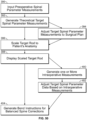
- the processing system may be further programmed to receive preoperative spinal parameters, input planned or target spinal parameters, and/or track intraoperative measurement of those parameters.
- the processing system is further configured to preview and display the results of these clinical objectives and/or predetermined functions to the user in a meaningful way.
- One or more surgical procedures may be performed using the system.
- a system for intraoperative planning and assessment of spinal deformity correction during a surgical spinal procedure comprising: a spatial tracking system comprising an IR sensor and an IR tracking array, said IR tracking array being arranged along a proximal end of a surgical pointer tool capable of digitizing the location of an implanted surgical device and relaying to the spatial tracking system via the IR sensor; a control unit in communication with the spatial tracking system, said control unit being configured to: (a) receive the digitized location data of a plurality of implanted screws; (b) receive the digitized location data of at least one anatomical reference point; (c) generate at least one virtual anatomic reference line based on the digitized location data of said at least one anatomical reference point; (d) accept one or more spine correction inputs; and (e) generating at least one rod solution output shaped to engage the screws at locations distinct from the digitized location.
- a spatial tracking system comprising an IR sensor and an IR tracking array, said IR tracking array being arranged along
- the spine correction input is a spine correction in the coronal plane.
- the spine correction input comprises aligning all of the digitized screw locations relative to the CSVL in the coronal plane.
- the system generates a rod solution output that includes T a vertically straight rod along at least a portion of the length.
- the virtual anatomic reference line is the central sacral vertical line (CSVL).
- the at least one anatomical reference point comprises at least two points that correlate to the CSVL.
- the at least one anatomical reference point comprises two points that lie along the CSVL.
- the at least two points are the left iliac crest, the right iliac crest, and the midpoint of the sacrum.
- the at least one anatomical reference point comprises a superior point and an inferior point on the sacrum.
- the control unit is configured to generate at least one measurement value based on at least two anatomically-based reference lines. According to some implementations, this measurement value may be an offset distance between the two reference lines. According to some implementations, the two reference lines are the central sacral vertical line (CSVL) and the C7 plumb line (C7PL). According to yet other implementations, the control unit is further configured to assess intraoperative spinal balance based on a relationship between said CSVL and C7PL and communicate that assessment to a user. In some implementations, the r relationship may be based on the coronal offset distance between the CSVL and C7PL. In yet other implementations, the communication may be a color.
- the communication may be such that a first color designates an offset distance indicating a balanced spine within the coronal plane and a second color designates an offset distance indicating an unbalanced spine within the coronal plane.
- the control unit is configured to generate at least one measurement value based on at least one anatomically-based reference point.
- the measurement value comprises an intraoperative lumbar lordosis angle and a planned pelvic incidence angle.
- the control unit is further configured to assess intraoperative spinal balance based on a relationship between an intraoperative lumbar lordosis angle measurement and a planned pelvic incidence angle.
- the lumbar lordosis angle and pelvic incidence angle may be measured at least once during the operation progress.
- the relationship between lumbar lordosis and pelvic incidence may be based on the variance between the intraoperative lumbar lordosis angle and the planned pelvic incidence angle.
- the communication may be a color.
- a first color may designate variance indicating a balanced spine within the sagittal plane and a second color designates a variance distance indicating an unbalanced spine within the sagittal plane.
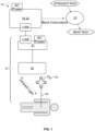
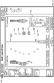
- a surgical planning, assessment, and correction system 10 including a spatial tracking system 12 to obtain the location of one or more surgical implants 14, a control unit 16 containing software to convert the implant locations to a series of bend instructions, and a bending device 18 to execute the bend instructions.
- the spatial tracking system 12 includes an IR position sensor 20, a digitizer pointer 23, as well as other components including Host USB converter 21.
- the spatial tracking system 12 is in communication with control unit 16.
- the control unit 16 has spatial relation software and C-arm video import capabilities and is communicatively linked to the display 32 so that information relevant to the surgical procedure may be conveyed to the user in a meaningful manner.
- the relevant information includes, but is not limited to, spatial positioning data (e.g., translational data in the x, y, and z axes and orientation/rotational data R x , R y , and R z ) acquired by the IR position sensor 20 and intraoperative fluoroscopic images generated by the C-arm fluoroscope.
- the system 10 comprises a neuromonitoring system communicatively linked to the spatial tracking system 12 and/or the C-arm via the control unit 16.
- the neuromonitoring system may be the neuromonitoring system shown and described in U.S. Patent No. 8,255,045, entitled “Neurophysiologic Monitoring System” and filed on April 3, 2008 .
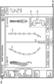
- Figs. 2-9 depict the various components of one or more digitizer pointers 23.
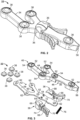
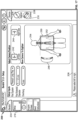
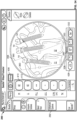
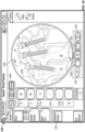
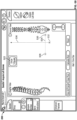
- Figs. 2-4 detail an example IR-reflective tracking array 22 component of the digitizer pointer 23, according to the invention.
- Array 22 includes a housing 34, bilateral shutters 36, and a plurality of IR-reflective spheres 38 arranged in a calculated manner at various locations on the array 22 such that their position information is selectively detectable by the IR position sensor 20.
- Housing 34 comprises a top housing 40, bottom housing 42, and a distal threaded aperture 56 configured to threadably receive the threaded end 78 of a stylus (e.g., stylus 24, 26, 28, and/or 30).
- Top housing portion 40 is further comprised of upper portion 44, underside 46, and sides 48.
- a plurality of sphere apertures 52 extend between upper portion 44 and underside 46 and are sized and dimensioned to receive reflective spheres 38 within recessed pockets 54.
- Each side 48 includes cutout 50 sized and dimensioned to receive tongue 70.
- Bottom housing 42 is comprised of a first face 58 and a second face 60.
- the first face 58 includes nesting platforms 62 and bullet posts 64.
- Each shutter 36 includes handle portion 66, cover portion 68, tongue 70, interdigitating gear teeth 72, and channel 74 for receiving bullet posts 64.
- a spring 76 extends between the two shutters 36 and is held in place via spring posts 71.
- each IR-reflective sphere 38 is nested on a platform 62.
- Top housing 40 is placed over bottom housing 42 in a snap fit configuration such that each IR-reflective sphere 38 fits within a recessed pocket 54 within its respective sphere aperture 52.
- bilateral shutters 36 are positioned over the housing 34 with tongues 70 sliding into cutouts 50 such that each shutter cover 68 obscures exactly one half of the IR-reflective sphere 38 (for example, the middle IR-reflective sphere 38) as depicted in Fig. 2 .
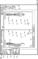
- the IR-reflective tracking array 22 mates with one or more surgical objects (for example styluses 24, 26, 28, 30).
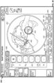
- Each stylus 24, 26, 28, 30 includes a threaded proximal end 78 for mating with the threaded distal aperture 56 of the IR-reflective tracking array 22, elongate shaft 80, and shaped distal tip 82.
- Shaped distal tip 82 may be any shape that is complimentary to, and fits securely within, the shape of a particular screw head.
- Fig. 6 shows styluses 24, 26, 28, and 30 each with a different shaped distal tip designed to mate with different open screw systems, minimally-invasive screw systems, and closed tulip, iliac, and offset connector systems.
- the distal tip 82 is preferably inserted into each screw while orienting the digitizer pointer coaxial to that screw (or other fixation device).
- the length of the elongate shaft 80 is fixed relative to the array 22 such that all digitized points are a consistent length from the geometry of the IR-reflective markers 38 and position information may be obtained from this relationship.
- the length of the elongate shaft 80 is adjustable relative to the array 22 such as that shown with stylus 30, effectively elongating the distance from the digitized point and the IR-reflective markers. This longer distance translates to digitization of a point above the actual screw head based on the distance the user adjusted the elongate shaft 80.
- the resulting bend instructions would shape a rod that traverses that point above the screw allowing the user to reduce the screw to the rod.
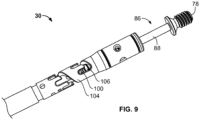
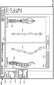
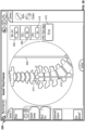
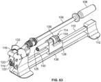
- offset pointer 30 includes an elongate tubular member 84 and an inner piston 86.
- Elongate tubular member 84 is comprised of a milled helical slot 104 and a plurality of offset depth slots 106 located around the helix that correspond to a plurality of offset distances as will be described below.
- Inner piston 86 includes shaft 88, T-shaped cap 92, springs 94, and bushing 96.
- the T-shaped cap 92 is positioned over the proximal end of the shaft 88 and is preferably welded to the proximal end 105 of the elongate tubular member 84.
- Springs 94 are slideably positioned along the length of the shaft 88 between the distal end 93 of the T-shaped cap 92 and bushing 96.
- Bushing 96 is positioned over the distal end of the shaft 88.
- Pin 100 is travels through, and protrudes laterally from, slots 90, 98 on the inner shaft 88 and bushing 96, thereby securing the bushing 96 to the inner shaft 88.
- the pin 100 is sized and dimensioned such that it travels through the helical slot 104 and be positioned within each of the offset depth slots 106.
- the offset pointer 30 gives the user the ability to execute planned screw movement by a specific, pre-determined amount.
- the user inserts the offset pointer 30 into the screw head. Keeping the distal tip 82 engaged to the screw head, the user then selects an offset amount to be added to the screw and angles the offset pointer 30 in the direction he or she wishes to apply the offset to.
- the shaft 88 is pulled away from the array 22 and twisted until the pin 100 falls into the desired offset slot 106. As the shaft 88 is pulled, it telescopes in and out of the elongate tubular member 84 such that the distance between the shaped distal end 82 and the array 22 is increased.
- Offset options for sagittal correction may be provided, by way of example only from 0mm to 16mm offsets in 2mm increments.
- the system 10 will then acquire position information at that point in space as opposed to where the screw sits, allowing for sagittal correction of one or more vertebral levels.
- the digitizer pointer 23 may be used to acquire positional information about some or all screw locations.
- the shaped distal tip 82 may be coaxially aligned into the screw head and the array 22 is triggered to register the screw point.
- Screw locations may be digitized in a superior-inferior or inferior-superior direction.
- the first screw location digitized correlates to the rod insertion direction component of the bend instructions (described below).
- Squeezing handles 66 activates the spring mechanism and permits the shutters 36 to open equally via the interdigitating gear teeth 72 ( Fig. 4 ).
- Opening the shutter covers 68 exposes the middle IR-reflective sphere 38 and allows the IR tracking array 22 to be "seen” by the IR position sensor 20 and the position of the digitizer pointer 23 to be digitized. In this way, the IR position sensor 20 only recognizes the digitizer pointer 23 once the middle sphere 38 is exposed which allows for point-by-point tracking and obviates the sensing and digitization of one or more unnecessary data points which may occur with prior art systems that continually track surgical objects. Further, use of the gear mechanism allows the passive IR-reflective sphere 38 to be "seen” symmetrically by the IR position sensor 20, thereby enabling a more accurate calculation of position information by the system 10.
- control unit 16 emits an audible sound to notify the user that the middle sphere 38 is recognized by the IR position sensor 20 and the screw point is acquired. Once a point has been registered, the shutter handles 66 may be released, thereby closing the bilateral shutters 36. This process is then repeated for all screw locations to be digitized.
- the surgical bending algorithms may be divided into two smaller sub-systems: (1) the spatial location algorithms that acquire, collect, and digitize points in space and (2) the bending algorithms that analyze the points and calculate the bend instructions and rod length needed to bend a rod with the mechanical bending device 18.
- the spatial tracking system 12 measures the six degrees of freedom (6 DOF) information for the tracked IR-reflective spheres 38. These data provide the full pose (position and orientation) of each screw of interest which may then be made available to the algorithm library to calculate the bend instructions.
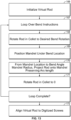
- Fig. 10 is a flow chart indicating the steps of the spatial location data acquisition process according to one example.
- the system 10 initializes the sensor objects from configuration to connect to, control, and read data from the IR position sensor 20 (step 140).
- the system 10 inspects all devices connected to it and finds the device with a device ID that corresponds to the IR position sensor 20 (step 141).
- step 142 if an IR position sensor 20 is found at step 141, the system 10 continues to establish a connection with the IR position sensor 20 (step 143). However, if not the system 10 continues to search. After the system 10 connects to the IR sensor 20, it then loads a tool file that defines the array 22 (step 144). After initialization and tool file loading, the IR sensor 20 must prepare for taking data. At step 145, the IR sensor 20 is enabled and ready to generate positional data but is left idle until tracking is enabled. By way of example and as described with reference to Fig. 17 , selecting the position of the IR sensor 20 with respect to the patient's body causes the control unit 16 to send the IR sensor 20 a command to begin tracking.
- the IR sensor 20 may be polled to for data (step 147).
- new data is requested twenty times per second from the IR sensor 20.
- the data generated from polling the IR sensor 20 is checked to ensure that it is reporting valid data.
- the data may be considered valid if all of the IR-reflective spheres 38 are visible to the IR sensor 20, the digitizer pointer 23 is fully inside the IR sensor's 20 working volume, there is no interference between the IR sensor 20 and the digitizer pointer 23, and both the location and rotation information reported are not null.
- the data is not deemed valid, then the digitized point is not used by the system 10 and polling is resumed.
- the process of collecting positional data for the bend algorithm commences. If the middle sphere 38 is not visible, then the data is available to the system 10 only to show proximity of the IR sensor 20 and IR-reflective tracking array 22 (step 151). Points used by the bend algorithm are preferably an average of several raw elements (step 152). Normally, five points are collected at this step before the points are processed and made available to the bend algorithm. The position data is averaged using a mean calculation. The directions are averaged in the quaternion representation (raw form) then converted to a unit direction vector. The data is rotated from the spatial tracking system 12 coordinate from into the system 10 coordinate frame using a rotation matrix. At step 153, after all processing, the data is available for the bend algorithm to collect and process further as will be described in greater detail below.
- the surgical bending software takes the location and direction data of the screw locations as described above and uses one or more geometry-based algorithms to convert these relative screw locations into a series of bend instructions.
- Fig. 11 is a flow chart indicating the steps of the surgical bending process according to a first example.
- the system 10 may validate the system inputs to ensure the rod overhang is greater than zero, validate the sensor setup to ensure that the IR sensor 20 location has been set, and validate each of the acquired points.
- the validation of each of the acquired points ensures, for example, that there are at least two screw points digitized, no two screw locations are too far apart, no two screw locations are too close together, and the span between the superior-most and inferior-most screw locations is not longer than the longest available rod.
- the data may be centered and aligned such that the first data point acquired is set at the system 10 coordinate's origin and all data is aligned to the x-axis of the system's coordinates thereby reducing any potential misalignment of the IR sensor 20 relative to the patient's spine.
- the system 10 may perform rod calculations for a straight rod solution, a pre-bent rod solution, and a custom-bend solution.
- a straight rod solution the system 10 first determines the length of a straight rod that will span all of the screw locations. This length may be calculated to accommodate each of the screw heads, hex and nose lengths of the rods chosen, and the user's selected rod overhang length.
- the system 10 fits the data to a straight line, if the screw data is within tolerance of the straight line, then the bend instructions will return a straight rod, otherwise it will return no rod solution and proceed to look for a pre-bent rod solution.
- the tolerance may be 2mm in each of the sagittal and coronal planes.
- the system 10 For a pre-bent rod solution, the system 10 first determines the length of the shortest pre-bent rod from the available rod from the available rods (as will be described in greater detail below) that will span all of the screw locations. This length may be calculated to accommodate each of the screw heads, hex and nose lengths of the rods chosen, and the user's selected rod overhang length. Next, the system 10 fits the digitized screw data to a circular arc in 3-dimensional space. If the screw data is within the tolerance of the arc, then the bend instructions will return a pre-bent rod solution, otherwise it will return no rod solution and proceed to look for a custom-bend rod solution. By way of example, this tolerance may be 2mm in each of the sagittal and coronal planes.
- Fig. 12 depicts a flow chart of a custom bend algorithm according to one example.
- screw location and direction data is generated by the spatial tracking system 12 as set forth above. The data is then projected into two planes: the x-y plane (coronal view) and the x-z plane (sagittal view). Each projection is then handled as a 2D data set.
- a fixed size loop is generated over small incremental offsets for the first bend location for the end of the rod which optimizes the ability of the bend reduction step 162 to make smooth solutions.
- the system 10 creates a spline node at each screw location and makes a piecewise continuous 4 th order polynomial curve (cubic spline) through the screw points.
- the smooth, continuous spline is sampled at a regular interval (e.g., every 1 cm) along the curve to generate an initial set of proposed bend locations.
- a regular interval e.g., every 1 cm
- as many bends as possible are removed from the initial set of proposed bend locations from step 161 as possible to reduce the number of bends the user must execute on a rod in order to fit it into a screw at each digitized screw point.
- no bend is removed if eliminating it would: (1) cause the path of the bent rod to deviate more than a predefined tolerance limit; (2) cause any of the bend angles to exceed the maximum desired bend angle; and (3) cause the rod-to-screw intersection angle to exceed the maximum angulation of the screw head.
- the 2D data sets are combined and handled as a 3D data set.
- the 3D line segments are then evaluated based on distance between each line segment interaction (Location), the angle between two line segments (Bend Angle), and the rotation (Rotation) needed to orient the bend into the next bend plane using the following calculations: Location: ((X 2 - X 1 ) 2 + (Y 2 - Y 1 ) 2 + (Z 2 + Z 1 ) 2 ) 1 ⁇ 2
- Bend Angle arc-cosine(V 12 • V 23 ) where • is the dot product and V is a vector between 2 points
- Rotation arc-cosine(N 123 •N 234 ) where • is the dot product and N is the normal vector to a plane containing 3 points.
- the "spring-back" equation for that rod will formulate that a 25 degree bend needs to be executed in order for it to spring-back to 20 degrees.
- the length of the final rod is the total of all the calculated distances plus the selected rod overhang.
- the loop is completed (step 163).
- the system 10 may output the rod solution having the smallest maximum bend angle (i.e., the smoothest bent rod). It is to be appreciated that the system 10 may choose the rod solution displayed based on any number of other criteria.
- the system 10 then generates the three-dimensional locations of the bends in space.
- the system 10 generates instructions for the user to choose a straight rod, a pre-bent rod, or to custom bend a rod (step 157). All of the output instructions are human-readable strings or characters. In all cases, the length of the required rod is calculated as described above and is displayed to the user as either a cut rod or standard rod. For custom bend solutions, rods are loaded into the bender with the "inserter end" (e.g., one pre-determined end of the rod) into the bender collet 126.
- the instructions are flipped, and the cut (or nose) end of the rod is instructed to be put into the bender collet 126.
- the bend instructions are generated from the geometric bend locations and are given as "Location”, “Rotation”, and “Bend” values as will be described in greater detail below. These values correspond to marks on the mechanical bender 18.
- Figs. 13-14 depict a flow chart of a second example of a custom bend algorithm.
- the custom bend algorithm includes a virtual bender used to render a virtual rod.
- the following calculations and the flowcharts of Figs. 13-14 highlight the steps of this example.
- a virtual bender (B) consists of a mandrel (M) of radius M r (mm).
- M mandrel
- M r radius
- the key assumption when bending the virtual rod around M is the conservation of arc length.
- ⁇ d R ⁇ d R ⁇
- the virtual rod, R is bent according to a list of instructions. Each instruction consists of a location ( I l ), rotation ( I r ), and bend angle ( I ⁇ ) .
- the location is the position of the rod in the bender and corresponds to the point directly under the mandrel M.
- the rotation is given in degrees (0°- 360°) and corresponds to the amount the rod is rotated from 0 in the collet.
- the bend angle is given by a single letter that corresponds to a specific angle in degrees. There is a corresponding notch on the bender with the same letter for the user to select.
- i 0 N r ⁇ 1 which effectively orients the virtual rod to be at zero rotation in the virtual bender.
- the system 10 rotates the virtual rod around the x-axis by I r (step 168).
- the system 10 finds the point r ⁇ i that matches I l .
- the virtual rod is translated by -r ⁇ i .
- each rod point from i to i + M r * I ⁇ is projected onto the mandrel M while preserving segment length (step 169-170).
- the virtual rod is then rotated around the x-axis by angle -I r .
- the next step is to align the bent virtual rod to the acquired screw positions (step 172).
- the alignment process has two stages-first, the system 100 finds the optimum rotation coarse scale (step 174). Second, the system performs the iterative closest point iteration algorithm fine scale.
- the system first initializes the result close to a global minimum (step 173).
- T ⁇ denote the optimum 3D rotation matrix
- T ⁇ UV T
- the virtual rod is rendered at step 180.
- 0, then the middle point of the triad (in this case r 1 ) is redundant, provides no new information to the geometry of the rod and may be removed.
- the virtual bender may be capable of bending a rod at any location of any angle perfectly to observe arc length.
- Using a virtually bent 3D rod to determine problem screws i.e. screw locations with a high screw-rod fit error
- a Markov chain is a sequence of random variables, X 0 , X 1 ..., such that the current state, the future and past states are independent.
- p X n + 1 x
- X 0 x 0
- X 1 x 1 , ...
- X n x n
- X n x n
- the likelihood or error function may be constructed based on how well the virtual rod fits the data.
- the rod is fit to the data in the least squares sense.
- N b denotes the number of bend
- Equation (3) there has been introduced a prior to control the number of bends introduced into the rod.
- This probabilistic approach to bend instruction generation allows for tailoring of constraints, for instance, a prior on the severity of the bends could also be introduced. Further, a prior could be introduced on how to define how close to the screws the bends may be located. This prior may have a "preferred" value, but probabilistically, there may be an optimal solution away from this idealized value.
- some hypothesized rules that may be applied to this algorithm include, but are not limited to: birth move: add a bend to the current solution; death move; remove a bend from the current solution; update move: translate rod points along the rod. Use of this example may provide more potential rod solutions to the user.
- the system 10 is typically utilized at the end of a posterior or lateral fixation surgical procedure after screws, hooks or other instrumentation have been placed, but prior to rod insertion.
- the system 10 obtains position information of the implanted screw positions and outputs bend instructions for a rod shaped to custom-fit within those implanted screws.
- pertinent information is inputted into the system via a setup screen.
- the user designates the side for which a rod will be created (patient's left or right side).
- the system 10 digitizes the screw locations.
- the system 10 outputs bend instructions.
- the user bends the rod according to the bend instructions. Steps 190-198 may then be repeated for a rod on the contralateral side of the patient if desired.
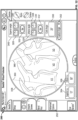
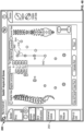
- Fig. 16 illustrates, by way of example only, one example of a screen display 200 of the control unit 16 capable of receiving input from a user in addition to communicating feedback information to the user.
- a graphical user interface GUI
- the screen display 200 may contain a header bar 202, a navigation column 204, device column 206, and a message bar 208.
- Header bar 202 may allow the user to view the date and time, alter settings, adjust the system volume, and obtain help information via date and time display 210, settings menu 212, volume menu 214, and help menu 216 respectively.
- Selecting the settings drop-down menu 212 allows the user to navigate to system, history, and shutdown buttons (not shown). For example, choosing the system button displays the rod bending software version and rod bender configuration file; choosing the shutdown option shuts down the rod bending software application as well as any other software application residing on the control unit 16 (e.g. a neuromonitoring software application); and choosing the history option allows the user to navigate to historical bend points/instruction data in previous system sessions as will be described in greater detail below. Selecting the help menu 216 navigates the user to the system user manual.
- navigation column 204 contains various buttons (e.g., buttons 218, 220, 222, 224, 226) for navigation through various steps in the rod bending process. Pressing button 204 expands/minimizes the details of the navigation column.
- Devices column 206 contains various buttons indicating the status of one or more devices associated with the system 10. By way of example, devices column 206 may include buttons 228 and 230 for the digitizer 23 and IR sensor 20 components of the system 10, respectively. Pressing button 206 expands/minimizes the details of the devices column.
- pop-up message bar 208 communicates instructions, alerts, and system errors to the user.
- Figs. 16-17 depict an example setup screen.
- the system 10 Upon selecting setup button 218 on the display screen 200, the system 10 automatically initiates the setup procedure.
- the system 10 is configured to detect the connection status of each of its required components.
- icons 228, 230 indicate the connectivity and activity status of the digitizer 23 and IR sensor 20, respectively. If one or more required components are not connected or are connected improperly, the display 200 may alert the user to address the issue before proceeding via textual, audio, and/or visual means (e.g., textual messages, audible tones, colored icons or screens, blinking icons or screens, etc.).
- the digitizer icon 228 is a status indicator for the active acquisition and/or recognition of the digitizer and the presence and background color of the icon 228 may change to indicate the digitizer tracking status.
- the icon 228 may be absent when the system 10 is not acquiring screws and does not recognize the digitizer, gray when the system 10 is not acquiring screws and recognizes the digitizer, green when the system 10 is in screw acquisition mode and recognizes the digitizer, and red when the system 10 is in screw acquisition mode and does not recognize the digitizer.
- Pressing button 206 expands/minimizes the details of the device column 206. Depending on the type of surgery, type of patient deformity, etc., it may be advantageous for the user to choose a digitizer from a selection of different digitizers.
- pressing icon 228 expands a pull-out window for the different stylus options available with the system 10 (e.g., styluses 22, 24, 26, 30 as described above).
- the IR sensor graphic icon 230 is a status indicator for the IR sensor 20. The presence and background color of the icon 230 may change to indicate the status of the IR sensor 20.
- the icon 230 may be absent when the system 10 does not recognize the IR sensor 20, gray when the system 10 recognizes the IR sensor 20 is connected to the system 10, and red when the system 10 senses a communication or bump error for the IR sensor 20.
- the IR sensor 20 should be recognized if it is connected after initialization of the bending application.
- the user may then input one or more pieces of case-specific information from one or more drop-down menus.
- drop-down menus for rod system 234, rod material/diameter 236, rod overhang 238, procedure type (not shown), and anatomical spinal levels of the surgical procedure may be accessed from the setup selection panel 232 of the screen display 200.
- the rod system drop-down menu 234 allows the user to choose the rod system he/she plans to use. This selection drives choices for the rod material/diameter 236 drop-down menus.
- the system 10 may be programmed with numerous fixation options from one or more manufacturers.
- the fixation system selections for one manufacturer only e.g. NuVasive ® Precept ® , Armada ® , and SpherX ® EXT.
- the user may also choose the combination of rod material (e.g. titanium, cobalt chrome, etc.) and rod diameter (e.g. 6.5 mm diameter, 5.5 mm diameter, 3.5 mm diameter, etc.).
- the drop-down menu 238 for material and diameter options may preferably be dependent upon the choice of rod system. Because the geometry and sizes can vary between manufacturers and/or rod systems, programming the system 10 with these specific inputs can aid in outputting even more accurate bend instructions.
- the user may also choose the amount of overhang from the rod overhang pull-down menu 238.
- the amount of overhang may be selectable in 0mm, 2.5mm, 5 mm, 7.5mm, and 10mm lengths.
- this function prescribes a symmetric overhang on both the superior and inferior ends of the rod.
- this function also prescribes different overhang lengths on either end of the rod based on user preference and patient anatomical considerations.
- the system 10 also contains functionality for accommodating multiple rod diameters and transitional rods as used, for example in Occipital-Cervical-Thoracic (OCT) fusion procedures
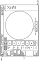
- the system 10 aids the user in setting up the IR sensor 20 in an optimal position for positional data acquisition.
- any visual (textual, graphic) indicator may be used to indicate the IR sensor placement instructions.
- an active graphic directs the user to position the IR sensor 20 relative to the digitizer array 22 held static within the patient's body. As shown in Fig. 17 , the user first selects the side of the patient the IR sensor 20 is located on by selecting the left side sensor position button 242 or right side sensor position button 244 in the IR sensor setup panel 240.
- a the IR sensor positioning panel 246 such that sensor graphic 248 and a tracking volume box graphic 250 appear on the display screen 200.
- Tracking volume box 252 that moves with the sensor graphic 248 as the IR sensor 20 is moved.
- the user positions the digitizer array 22 into the body of the patient. Once recognized by the system 10, a target volume box 252 (which may be displayed as white in color) is positioned over the patient graphic 254.
- the user moves the IR sensor 20 relative to the digitizer array 22 until the tracking volume box 250 matches up to the position of the target volume box 252.
- the sensor graphic 248 increases in size if it is moved superior to the target tracking volume and decreases in size if it is moved inferior to the target volume.
- the tracking volume box 250 may be color-coded to depict the relative distance to the target volume. By way of example, the tracking volume box 250 may be depicted in red if the distance to the target volume is outside of a certain distance in one or more axes (e.g., outside ⁇ 8cm in all 3 axes.) and green if within or equal to ⁇ 8cm in all 3 axes.
- a graphic (e.g., a check) may appear on setup button 218 to indicate such a completion and the system 10 proceeds to step 192 in the flowchart of Fig. 15 .
- the user designates which side of the patient's spine to acquire digitized positional information from by selecting either the Left "L" toggle/status button 220 or Right “R” toggle/status button 222. The user then selects the Acquire
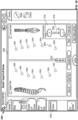
- Screws button 224 which navigates the display screen 200 to an Acquire Screws (left or right) screen shown by way of example in Figs. 18-20 .
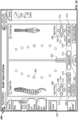
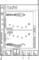
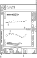
- the display screen 200 includes a sagittal view panel 256 and a coronal view panel 258 with spine graphics 260, 262 in each of the sagittal and coronal views, respectively.
- Spine graphic 260 may flip orientation depending on which side of the spine the user is digitizing (left or right). Additionally, spine graphic 262 may highlight the side of the patient the user is digitizing (left or right). The user may digitize the location of each implanted screw using, by way of example, the digitizer pointer 23 as described above.
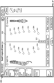
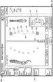
- each screw point 264 is digitized, its relative location with respect to the other acquired screw points 264 can be viewed in both sagittal and coronal views via the sagittal view panel 256 and the coronal view panel 258 as shown in Fig. 19 .
- the last screw point digitized may have a different graphic 266 than the previously-acquired screw points 264 (by way of example, the last screw point acquired 266 may be a halo and the previously-acquired screw points 264 may be circles).
- the screws locations may be digitized from a superior-to-inferior or inferior-to-superior direction and according to some examples, the system 10 can detect which direction the digitization is occurring in after the acquisition of two consecutive screw point locations.
- the user wishes to delete a digitized screw point, he/she may do so by pressing the "Clear Point” button 270. If the user wishes to delete all digitized screw points, he/she may do so by pressing the "Clear All Points" button 268.
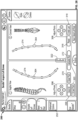
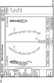
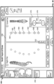
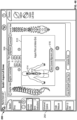
- the user may press the "Calculate Rod” button 272 which initiates the curve calculation preferably using one of the algorithms discussed above.
- a rod graphic 274 populates through the screw points 264, 266 and a confirmation graphic (e.g., a check) may appear on the "Acquire Screws" button 224 to indicate that the system 10 has generated a rod solution.
- the "Calculate Rod” button 272 becomes the "Undo Rod” button 272. If the user presses the "Undo Rod” button 272, the rod solution 274 is cleared and the user may acquire more screw points or clear one or more screw points.
- the system 10 may include a visual graphic for where along a rod the curve calculation is generating a severe bend (acute angle).
- the user may select "Undo Rod” button 272, perform one or more surgical maneuvers (e.g. reduce the screw, backup the screw, adjust the screw head, etc.), redigitize the screw point, and generate a more feasible solution. If the rod solution is acceptable to the user, the Screw Acquisition step 194 is complete and the system 10 proceeds the Bend Instructions step 196 in the flowchart of Fig. 15 .
- the system 10 may display the offending point resulting in the severe bend angle in red and offer the next-best solution that includes a bend angle falling within a pre-determined range of angles for that bender. If the rod solution is acceptable to the user, the Screw Acquisition step 194 is complete and the system 10 proceeds the Bend Instructions step 196 in the flowchart of Fig. 15 .
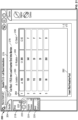
- the bend instructions panel 276 allows the user to view the bend instructions corresponding to the resulting rod solution in the Acquire Screws screen ( Fig. 20 ).
- the bend instructions panel 276 contains three fields containing various aspects of the bending instruction: upper message field 278, bender instructions field 280, and lower message field 282.
- the upper message field 278 may communicate the rod cut length, rod type, and/or rod loading instructions to the user (e.g. "Cut Rod: 175.00mm Load Inserter End Into Bender").
- the bender instructions field 280 displays rows 284 of bend maneuvers in location 286, rotation 288, and bend angle 290 to perform on the mechanical bender 18 as will be described in greater detail below.
- the lower message field 282 may communicate the direction of insertion or orientation of implanting the rod to the user.
- the lower message field 282 shown in Fig. 21 provides the following sample instruction: "Insert Rod head to foot.”
- the rod insertion direction into the patient is dependent on the sequence of screw digitization (superior-to-inferior or inferior-to superior).
- the bend instruction algorithm takes into account the orientation of the inferior, superior, anterior, and posterior aspects of the rod and ensures that these aspects are known to the user.
- the instructions for use direct the user to load the rod into the bender, the system 10 manages which bends are imparted on the rod first based on the severity of the bend angles. The section of the bend instructions with greater bend angles may be performed first then the straighter bend sections of the bend instructions may be performed last. Further, the instructions may also direct the user to align a laser line or orientation line on the rod to an alignment arrow (not shown) on the mechanical rod bender 18. This alignment controls the Anterior / Posterior orientation of the rod geometry and generates bend instructions accordingly.
- the user follows the bend instructions generated by the system 10 for location (location may be color-coded on the bender 18 and on the screen 200 as green triangle), rotation (rotation may be color-coded on the bender 18 and on the screen 200 as red circle), and bend angle (bend angle may be color-coded on the bender 18 and on the screen 200 as blue square), sequentially, starting at the first bend instruction and working sequentially until the final bend is completed. From here, the user may repeat steps 190-198 on the rod construct for the contralateral side of the patient's spine.
- a user may wish to toggle between left and right screens to view left and right digitized screw points, rod previews, and bend instructions for reference or comparison. Selecting the Left "L" toggle/status button 220 and right “R" toggle/status button 222 allows the user to do so.
- the GUI may additionally include a History feature. Selecting the History button (not shown) will allow the user to refer back to any previous rod bending solution. The user navigates to the Bend Instructions screen 226 based on choice of the L/R toggle buttons 220, 222 and pressing Bend Instruction button 226. If navigating to previous bend instructions, the Bend Instructions screen will display previous bend instructions. Once the user has selected the desired rod solution, the user then executes the bends using the mechanical bender 18.
- the system 10 obtains position information of the implanted screws (steps 192 and 194), accepts correction inputs via one or more advanced options features (step 195), and generates for viewing bend instructions for a rod shaped to fit at locations apart from those implanted screw positions (step 196) as depicted in the flowchart of Fig. 22 . Installing a rod shaped in this manner could correct a curvature or deformity in the patient's spine according to a user's prescribed surgical plan. Details of the system 10 are discussed now discussed with examples for obtaining a rod bent according to one or more surgical plans.
- selecting the "Advanced Options" button 292 expands an Advanced Options menu 292 from which the user may perform one or more corrections to the digitized screw points and the system 10 generates bend instructions that will achieve those desired corrections on the patient's spine once the rod is implanted and the screws are brought to the rod.
- a user may wish that the rod bend solution will consider a point that is not a digitized screw point in determining the bend instructions. According to some implementations, this point is an adjusted distance from the digitized screw point location. Selecting the "Adjust Points" button 296 from the Advanced Options menu 292 navigates the user to an Adjust Points screen as depicted in Fig. 23 . Selecting a digitized screw location of interest (for example the screw point represented as dot 304 in Fig. 24 ) highlights the screw point and brings up an adjust points control 306 in each of the sagittal and coronal views 256, 258.
- dot 304 changes color based on the distance from the originally digitized screw location as shown in Fig. 25 .
- that color corresponds to color-coded offset distance indicator 322 which provides visual feedback to the user as to the distance the point has been adjusted.
- dot 304 appears yellow in Fig. 25 indicating that the point has moved 4mm in each of the sagittal and coronal planes.
- the system 10 may have a maximum distance from the digitized point past which it will not allow the manipulated point to exceed (by way of example only, this distance may be 5mm). In other implementations, this distance may be depicted as a distance (for example, the numeral 18 in fig. 48 , indicating that a screw point is 18 mm from its original location).
- the user may adjust as many points as desired in this fashion. The user may reset all adjusted points to their original configurations via "Reset” button 316 or may undo the last adjusted point via the "Undo Last” button 318. Once satisfied with the adjusted points, the user may either proceed to one or more additional advanced options as set forth below or select "Calculate Rod" 272.
- the system 10 generates a rod in which the curve traverses the adjusted points, as in Fig. 26 , thereby creating a correction-specific rod and providing the user with the ability to correct the curvature or deformity in the spine according to his or her prescribed curve.
- a user may wish for a smoother rod bend.
- the "Virtual Point" button 320 shown by way of example in Fig. 25
- the system 10 allows the user to add an additional point anywhere in between the superior-most and inferior-most digitized screw locations. While there is no screw at this location, this point is taken into consideration during the curve calculation and may coerce the curve into a more natural shape yielding a smoother rod bend.
- the user may either proceed to one or more additional advanced options as set forth below or select "Calculate Rod” 272 and as described above, the system 10 generates a correction-specific rod solution 274 that the user may use to correct the spine to the shape of the rod.
- a pre-bent rod eliminates the need for making additional bends to a rod while assuring that a desirable rod curve is achieved.
- selecting the "View Pre-Bent Rod” button 298 from the Advanced Options menu 292 navigates the user to a "View Pre-Bent Rod” screen as depicted in Figs. 27-28 .
- the system 10 calculates and outputs the best pre-bent rod geometry based on the selected manufacturer's rod system that was chosen during the setup step 190 (e.g.
- NuVasive ® Precept ® displays the best fit virtual pre-bent rod solution 324 available on top of the digitized screw points for viewing in the sagittal and coronal views 256, 258 (see Fig. 28 ).
- the system 10 only generates a pre-bent rod solution if the geometry of the pre-bent rod fits the digitized screw points within a predetermined curve fitting tolerance (e.g. 7mm).
- a color-coded offset distance indicator 322 may provide the user with an indication of the distance each screw position will be from the pre-bent rod construct.
- the system 10 proceeds to the Bend Instructions step 196 which displays the corresponding pre-bent rod specifications in the Bend Instructions Screen ( Fig. 29 ).
- the upper message field 278 instructs the user that, based on the digitized screw points, an 85.0mm pre-bent rod is recommended. From here, the user may decide whether the patient's anatomical and surgical requirements would be better suited with a pre-bent option or a custom-bent option. Armed with the information from Figs. 27-29 , the user may then adjust the screw positions to fit the pre-bent rod if needed (e.g., adjust the screw head, adjust the screw depth, etc.).
- a user may want to align or correct the patient's spine in the sagittal plane (i.e., add or subtract lordosis or kyphosis).
- the system 10 includes a sagittal correction feature in which the user is able to measure the amount of lordosis in the spine and adjust angles in the sagittal plane. The system 10 then incorporates these inputs into the bend algorithm such that the rod solution includes the desired alignment or correction.
- Selecting the "View Vectors" button 300 from the Advanced Options menu 292 initiates the sagittal correction feature.
- the user may select at least two points of interest and the system then determines the appropriate vector in the sagittal view.
- the angles are measured and adjusted based on the screw trajectory screw axis position) using the digitized screw data acquired in the Acquire Screws step 194.
- the user selects at least two screw points of interest (e.g., screw points 338 and 342).
- the system 10 measures the angle between the screw trajectories (shown here as 35 degrees).
- the system 10 may measure the total amount of lumbar lordosis by measuring the lumbar lordosis angle 334 in the superior lumbar spine (shown in Fig. 30 as 15 degrees) and the lumbar lordosis angle 336 in the inferior lumbar spine (show in Fig. 30 as 35 degrees).
- the angle adjustment buttons 328, 330 on the Angle Adjustment Menu 326 the user may increase or decrease the desired angle correction of the spine in the sagittal plane (i.e., add or subtract lordosis or kyphosis superiorly or inferiorly). As the angle is adjusted, the angular position 336 between the two screw points 338, 342 is changed as well.
- the system 10 may include a color-coded offset distance indicator 322 to provide the user with an indication of the distance each digitized screw position will be adjusted in the sagittal plane as described above.
- the user may select the "Set” button 332, and then the "Calculate Rod” button 270.
- the system 10 displays a rod solution 274 incorporating the user's clinical objective for correction of the spine in the sagittal plane as depicted in Fig. 33 .
- the superior and inferior lumbar lordosis angles 334, 336 are measured, displayed, and adjusted referencing anatomy from an imported lateral radiographic image.
- lateral radiographic image 358 may be inputted into the system 10.
- the user may touch the screen 200 and move lines 360 over at least two points of interest (e.g. the superior endplate of V1 and the inferior endplate of V3) and the system 10 then then measures the angle between the two lines 360.
- the user may increase or decrease the desired angle correction of the spine in the sagittal plane (i.e., add or subtract lordosis or kyphosis superiorly or inferiorly).
- the amount of adjustment is dynamically altered in its respective angle measurement box (i.e., either superior lumbar lordosis angle box 354 or inferior lumbar lordosis angle box 356).
- the user adjusts angle lines 360 as part of the inferior lumbar lordosis angle.
- the system 10 measures this angle as 20 degrees as depicted in angle measurement field 350.
- the user then uses button 330 in superior angle adjustment menu 346 to increase the angle. This change is depicted in inferior lumbar lordosis angle box 356. Once the desired amount of correction is achieved, in this example, it is achieved at 50 degrees.
- the user may then press the capture angle button 352 and this parameter may be correlated to the digitized screw positions corresponding to the vertebral levels that those angles were measured off of.
- the system 10 may include a color-coded offset distance indicator 322 to provide the user with an indication of the distance each digitized screw position will be adjusted in the sagittal plane as described above.
- the user may select the "Set” button 332, and then the "Calculate Rod” button 272.
- the system 10 displays a rod solution 274 incorporating the user's clinical objective for correction of the spine in the sagittal plane as depicted in Fig. 33 .
- the sagittal correction feature of the system will be able to account for any patient positioning-related deviations. It will also be appreciated that in addition to lordotic corrections, the sagittal angle assessment tool may be useful for other types of surgical maneuvers, including but not limited to pedicle subtraction osteotomy (PSO) procedures and anterior column reconstruction (ACR) procedures.
- PSO pedicle subtraction osteotomy
- ACR anterior column reconstruction
- a user may want to align or correct the patient's spine in the coronal plane (i.e., correct scoliosis).
- the system 10 includes one or more coronal correction features in which the user is able to view the patient's spine (and deformity) in the coronal plane via anterior-posterior x-rays; measure one or more anatomic reference angles; and/or persuade one or more screw locations towards a particular coronal alignment profile by manually or automatically biasing which direction the rod bend curve is adjusted.
- the system 10 may then incorporates these inputs into the bend algorithm such that the rod solution includes the desired alignment or correction.
- Selecting the "Coronal Correction" button 302 from the Advanced Options menu 292 initiates the coronal correction feature.
- the user may wish to ascertain the degree of coronal deformity by referencing spinal anatomy, measuring the coronal Cobb angles between two anatomical references in the coronal plane, and adjusting those angles intraoperatively as part of the surgical plan to bring the spine into (or closer to) vertical alignment.
- the coronal Cobb angles may be ascertained using anterior-posterior radiographic images.
- Anterior-posterior radiographic image 358 may be inputted into the system 10.
- the coronal Cobb angle may be determined by drawing lines parallel with the endplates of the most tilted vertebrae above and below the apex of the curve and measuring the angle between them. The user may touch the screen 200 and move lines 360 over at least two points of interest (e.g. the superior endplate of T11 and the inferior endplate of L3) and the system 10 then measures the angle between the two lines 360.
- the' user may increase or decrease the desired angle correction of the spine in the coronal plane (i.e., add or subtract correction to make the endplates of the superior and inferior vertebrae selected more parallel with one another).
- the coronal Cobb angle measurement may be dynamically altered in the coronal Cobb angle measurement box 350.
- the starting coronal Cobb angle is 58 degrees.
- the user uses buttons 328, 330 to reduce the angle lines 360 between T11 and L3. Once the desired amount of correction is achieved (shown, by way of example, in Fig.
- the user may then press the capture angle button 352.
- This parameter may be correlated to the digitized screw positions corresponding to the vertebral levels that those angles were measured off of.
- the system 10 may include a color-coded offset distance indicator 322 to provide the user with an indication of the distance each digitized screw position will be adjusted in the coronal plane as described above (not shown here).
- the user may select the "Set” button 332, and then the "Calculate Rod” button 272.
- the system 10 displays a rod solution 274 incorporating the user's clinical objective for correction of the spine in the coronal plane.
- the coronal Cobb angle may be displayed and adjusted referencing anatomy from digitized locations of screws placed in the left and right pedicles of the vertebrae of interest.
- the system links left and right digitized screw locations for each respective vertebrae (line 361) and measures the angle between the two lines 361 (shown here in Fig. 36 as 58 degrees).
- the coronal Cobb angle may be determined by selecting the screw location of the most tilted vertebrae above and below the apex of the curve. Using the angle adjustment buttons on the Angle Adjustment menu 326, the user may increase or decrease the desired angle correction of the spine in the coronal plane (i.e.
- the Cobb angle measurement may be dynamically altered as set forth above.
- the Cobb angle may displayed alongside the radiographic image (shown in Fig. 36 with a starting coronal Cobb angle of 58 degrees).
- the user uses the buttons in menu 326 to reduce the angle lines 361 between T11 and L3.
- the desired amount of correction shown, by way of example, in Fig. 37 as 0 degrees, the user may then press the "Set" button 332 and this parameter may be correlated to the digitized screw positions corresponding to the vertebral levels that those angles were measured off of.
- the system 10 may include a color-coded offset distance indicator 322 to provide the user with an indication of the distance each digitized screw position will be adjusted in the coronal plane as described above (not shown here). Once the desired amount of angular correction is achieved, the user may select the "Calculate Rod” button 272. The system 10 then displays a rod solution 274 incorporating the user's clinical objective for correction of the spine in the coronal plane.
- the user may select at least two points of interest and the system then generates a best fit reference line through all points including and lying between the at least two points of interest.
- the ideal correction of the spine in the coronal plane is a straight vertical line extending between the superior-most and inferior-most screw locations of interest.
- the user may wish to achieve a certain amount of correction relative to the ideal correction. From the display screen, the user may select a percentage of relative correction between the screw points as digitized (0% correction) and the best fit reference line (100%).
- the system calculates a rod solution and shows an off-center indicator 322 to provide a user with an indication of the distance each screw is from the coronally-adjusted rod construct as set forth above.
- the user may straighten all points within the construct (global coronal correction).
- the superior and inferior screw points 362, 364 are selected and the system 10 generates a best fit global reference line 366 through all points 362, 364, 368.
- the Coronal Correction Menu 370 the user manipulates the + and - buttons 372, 374 to adjust the percentage of correction desired.
- the amount of desired correction is shown as 100% on the percentage correction indicator 376, meaning the rod solution 274 will be a straight line in the coronal plane and all screw locations will be adjusted to fit the rod/line.
- the percentage correction indicator 376 As depicted in Fig.
- the system 10 may include a color-coded offset distance indicator 322 to provide the user with an indication of the distance each digitized screw position will be adjusted in the coronal plane as set forth above. If the user deems this an acceptable rod solution, the user selects the "Calculate Rod” button 272 to view the rod solution 274 ( Fig. 41 ) and receive bend instructions or proceeds to another advanced feature as will be described in greater detail below.
- the user may straighten a subset of the screw points within the construct (segmental coronal correction). Based on the sequence those points are inputted into the system, a best-fit segmental reference line is generated through the points in the direction of the last chosen point. If an inferior point 364 is selected first and then a superior point 362 is selected second, the system 10 will draw the best-fit segmental reference line 378 superiorly as shown in Fig. 42 . Conversely, if a superior point 362 is selected first and then an inferior point 364 is selected second, the system 10 will draw the best-fit segmental reference line 378 inferiorly.
- the user manipulates the + and - buttons 372, 374 to adjust the percentage of correction desired.
- the amount of desired correction is shown as 100% on the percentage correction indicator 376, meaning the rod solution 274 will be a straight line in the coronal plane and all selected screw locations will be adjusted to fit the rod/line.
- unselected screw locations 380 will not be adjusted to fit the rod/line and their relative locations will be inputted into the system 10 and taken into consideration when the rod calculation is made. As depicted in Fig.
- the system 10 may include a color-coded offset distance indicator 322 to provide the user with an indication of the distance each digitized screw position will be adjusted in the coronal plane as set forth above. If the user deems this an acceptable rod solution, the user selects the "Calculate Rod” button 272 to view the rod solution 274 ( Fig. 44 ) and receive bend instructions or proceeds to another advanced feature as will be described in greater detail below.
- segmental coronal correction may be achieved relative to the patient's central sacral vertical line (CSVL) instead of a best-fit segmental reference line running through two selected digitized screw locations.
- CSVL is the vertical line passing through the center of the sacrum that may serves as the vertical reference line for the patient's coronal deformity as well as a guide for spinal correction in the coronal plane in accordance with the coronal assessment and correction features of the present disclosure.
- Figs. 45-49 illustrate a method for using the CSVL line for assessing coronal deformity and achieving coronal correction according to one example.
- this method commences after all screws are implanted into the patient and digitized in the manner set forth above.
- the user generates one or more radiographic images of the sacrum, localizes a superior and inferior point on the sacrum, and marks those points (e.g., implants Caspar pins, marks the patient's skin with a marker, etc.).
- the user selects the "Alignment" button 506 ( Fig. 45 ).
- the user is prompted to digitize the marked skin points representing the superior and inferior sacral landmarks. As shown by way of example in Fig.
- box 510 may pop up to instruct the user of the various steps of the workflow.
- the superior point on the sacrum has already been digitized (shown as digitized point 512) and check mark 514.
- Box 510 further instructs the user to "Acquire Point at Inferior End.” Selecting "Clear Coronal Alignment Line” 516 to re-digitize the sacral points and/or exit out of the CSVL coronal correction feature.
- a dashed line 518 representing the patient's true CSVL line appears on the screen ( Fig. 47 ) and the digitized screw locations 264 are reoriented in system 10 relative to the CSVL line 518.
- the display 200 in the coronal view now represents the patient's current coronal curve relative to a vertical reference (CSVL).
- CSVL vertical reference
- the user may select two points (i.e., the screw segment) he/she would like to correct or straighten relative to the CSVL.
- the user selects points 542 and 544.
- the first point chosen 542 is the point of rotation of the segment and the origin of the straightening line 520.
- the second point 544 determines the direction of the straightening line 520.
- the straightening line 520 may be drawn parallel to the CSVL line 518 as the objective of coronal correction is to make the spine as vertical as possible in the coronal plane.
- the user selects the "Calculate Rod” button 272 to view the rod solution 274 ( Fig. 49 ) and receive bend instructions.
- the user now has a rod solution he/she can pull the screws to, knowing that it is straight relative to the CSVL line and therefore providing the desired correction of the coronal deformity.
- the user will and receive bend instructions or proceeds to another advanced feature as will be described in greater detail below.
- restoring a patient's spine to a balanced position may be a desired surgical outcome.
- the system 10 may include a Global Spinal Balance feature in which the control unit 16 is configured to receive and assess 1) preoperative spinal parameter measurements; 2) target spinal parameter inputs; 3) intraoperative spinal parameter inputs; and 4) postoperative spinal parameter inputs.
- One or more of these inputs may be tracked and/or compared against other inputs to assess how the surgical correction is progressing toward a surgical plan, assess how close the patient's spine is to achieving global spinal balance, and utilized to develop/refine an operative plan to achieve the desired surgical correction.
- Spinal parameters may comprise the patient's Pelvic Incidence (PI), Pelvic Tilt (PT), Sacral Slope (SS), Lumbar Lordosis (LL), Superior Lumbar Lordosis ( ⁇ LL), Inferior Lumbar Lordosis ( ⁇ LL), C7 Plumb Line offset (C7PL), and Thoracic Kyphosis (TK), T1 tilt, and Sagittal Vertical Axis (SVA) measurements.
- the target spinal parameter measurements may be a clinical guideline (by way of example only, the SRS-Schwab classification, or a patient-specific goal based on that patient's anatomy).
- these spinal parameters may comprise Pelvic Incidence (PI), Pelvic Tilt (PT), Sacral Slope (SS), Lumbar Lordosis (LL), Superior Lumbar Lordosis ( ⁇ LL), Inferior Lumbar Lordosis ( ⁇ LL), C7 Plumb Line offset (C7PL), and Thoracic Kyphosis (TK), T1 tilt, and Sagittal Vertical Axis (SVA) measurements.
- PI Pelvic Incidence
- PT Pelvic Tilt
- SS Sacral Slope
- ⁇ LL Superior Lumbar Lordosis
- ⁇ LL Superior Lumbar Lordosis
- ⁇ LL Inferior Lumbar Lordosis
- C7 Plumb Line offset C7 Plumb Line offset
- TK Thoracic Kyphosis
- SVA Sagittal Vertical Axis
- Fig. 50 depicts a flowchart indicating the steps of the Global Spinal Balance feature according to one example.
- the system 10 inputs a patient's preoperative spinal parameter measurements.
- the system generates theoretical target spinal parameter measurements (step 392).
- One or more target spinal parameter measurements may be optionally adjusted the user in accordance with a surgical plan a step 394.
- a target spinal rod may be scaled to match the patient's anatomy using the theoretical or adjusted target spinal parameter measurements from step 392 or 394. This scaled target rod may then be displayed 398 to the user.
- the system 10 may generate one or more measurements (step 400) during the surgical procedure.
- the target spinal parameter data may then be adjusted based on the intraoperative measurements from step 400.
- the system 10 may generate bend instructions for balanced spine correction.
- the user may input a patient's preoperative measurements into the system 10 as depicted, by way of example in Fig. 51 .
- Selecting the Pre-Op measurement button 404 allows the user to input measurements into PI, LL, Superior LL, Inferior LL, C7PL, and TK input fields 408, 410, 412, 414, 416, 418, and 420 respectively.
- Such pre-operative measurements may be obtained from manual measurement means imported from any number of commercially-available desktop and mobile software applications.
- pre-operative anatomical measurements may be used to understand the imbalance in the patient's deformed spine as well as help determine an operative plan to implant devices that would adjust or form the spine to a more natural balance (e.g., rods, screws, a hyperlordotic intervertebral implant, etc.).
- the global spinal balance feature allows the user to adjust the patient's anatomical measurement values to the user's preferred target spinal parameters for a balanced and/or aligned spine.
- selecting the target measurement button 406 populates measurements into input fields 410, 412, 414, 416, 418, 420 that represent an ideal or properly balanced spine. If the user accepts these target spinal parameters, the system 10 would output a theoretical rod solution comprising rod shapes and curves representing an ideal or properly balanced spine scaled and overlaid onto the digitized screw points as shown in Fig. 53 .
- the system 10 may also include a color-coded offset distance indicator 322 to provide the user with an indication of the distance each digitized screw position is from the rod solution in the sagittal and coronal planes as set forth above.
- a color-coded offset distance indicator 322 to provide the user with an indication of the distance each digitized screw position is from the rod solution in the sagittal and coronal planes as set forth above.
- the user may use buttons 422, 424, 426 to adjust these target spinal parameters.
- the user could then refer to the correction indicator 428 for an indication of how much correction (relative to the pre-operative and theoretical spinal parameters) would be achieved based on those adjusted input correction values.
- the user's input correction values would then drive the rod bending algorithm (based on the digitized screw locations) to a rod shape customized to the user's plan for that particular placement.
- the final rod could be positioned within the patient and the screws and spine would be adjusted to the rod at the desired alignment.
- spinal parameter inputs may be assessed intraoperatively.
- the user may wish to intraoperatively measure the amount of lumbar lordosis that has been achieved (for example, after placement of an intervertebral implant).
- the system 10 may include be configured to obtain or import one or more lateral images, generate one or more lines between two or more landmarks on the patient's anatomy, determine a relationship between those landmarks, and adjust one or more spinal parameters to be used in generating the rod solution.
- the user first selects the intraoperative measurement button 408.
- lateral radiographic image 358 may be inputted into the system 10.
- the user may touch the screen 200 and move lines 360 over at least two points of interest (e.g. the superior endplate of
- the system 10 measures the angle between the two lines 360. As shown in Fig. 55 , the system 10 measures this angle as 15 degrees as indicated in the angle measurement field 350.
- the system may compare the intraoperative measurement to the preoperative and/or target spinal parameter value and provide an indication to the user of how much correction has been achieved relative to the pre-operative and theoretical spinal parameters.
- the user may increase the desired angle of correction of the spine in the sagittal plane (i.e., add or subtract lordosis or kyphosis). As the angle is adjusted, the amount of adjustment may dynamically displayed within angle measurement field 350.
- the system 10 may include a color-coded offset distance indicator (not shown) to provide the user with an indication of the distance each digitized screw position will be adjusted in the sagittal plane as described above.
- a color-coded offset distance indicator (not shown) to provide the user with an indication of the distance each digitized screw position will be adjusted in the sagittal plane as described above.
- the user may press the "Set” button 332 and then the "Calculate Rod” button (not shown in this view).
- the system displays a rod solution 274 incorporating the user's intraoperative objective for correction of the spine in the sagittal plane.
- the user may also wish to intraoperatively measure the patient's pelvic incidence angle.
- selecting the intra-op measurement button 408 optionally brings up a PI assessment tool.
- the system 10 obtains a fluoroscopic image 452 of the patient's pelvis.
- the user first selects the femoral head button 432 and uses arrows 450 on the PI Adjustment Menu 448 to locate the center point of the femoral head 434.
- the user selects the posterior sacrum button 436 and uses arrows 450 to identify the posterior aspect of the sacral endplate 438.
- the user selects the anterior sacrum button 440 and uses arrows 450 to identify the anterior aspect of the sacral end plate 442.
- the user may press the "Draw PI" button 446 after which the system 10 automatically draws and measures the pelvic incidence angle 446 for the user.
- Fig. 57 depicts a flowchart indicating the steps of an intraoperative Global Spinal Balance assessment feature according to one example.
- the system 10 inputs a patient's preoperative spinal parameter measurements.
- the system generates theoretical target spinal parameter measurements (step 558).
- One or more target spinal parameter measurements may be optionally adjusted the user in accordance with a surgical plan at step 560.
- the system may measure one or more spinal parameter measurements intraoperatively and provide one or more indications to the user how the surgical procedure is progressing.
- the system may measure one or more spinal parameter measurements postoperatively to assess the final status of the deformity correction and balance achieved.
- the user may input a patient's preoperative measurements into the system 10 as depicted, by way of example in Fig. 51 .
- Selecting the Pre-Op measurement button 404 allows the user to input measurements into PI, LL, Superior LL, Inferior LL, C7PL, and TK input fields 408, 410, 412, 414, 416, 418, and 420 respectively.
- Such pre-operative measurements may be obtained from manual measurement means imported from any number of commercially-available desktop and mobile software applications.
- pre-operative anatomical measurements may be used to understand the imbalance in the patient's deformed spine as well as help determine an operative plan to implant devices that would adjust or form the spine to a more natural balance (e.g., rods, screws, a hyperlordotic intervertebral implant, etc.).
- the global spinal balance feature allows the user to adjust the patient's anatomical measurement values to the user's preferred target spinal parameters for a balanced and/or aligned spine.
- selecting the target measurement button 406 populates measurements into input fields 410, 412, 414, 416, 418, 420 that represent an ideal or properly balanced spine.
- buttons 422, 424, 426 may be used to adjust these target spinal parameters.
- spinal parameter inputs may be assessed intraoperatively.
- the user may wish to intraoperatively measure the amount of lumbar lordosis that has been achieved (for example, after placement of an intervertebral implant).
- the system 10 may include be configured to obtain or import one or more lateral images, generate one or more lines between two or more landmarks on the patient's anatomy, determine a relationship between those landmarks, and adjust one or more spinal parameters to be used in generating the rod solution.
- the user first selects the intraoperative measurement button 408.
- lateral radiographic image 358 may be inputted into the system 10.
- the user may touch the screen 200 and move lines 360 over at least two points of interest (e.g.
- the system 10 measures the angle between the two lines 360. As shown in Fig. 55 , the system 10 measures this angle as 15 degrees as indicated in the angle measurement field 350.
- the system may compare the intraoperative measurement to the preoperative and/or target spinal parameter value and provide an indication to the user of how much correction has been achieved relative to the pre-operative and theoretical target spinal parameters.
- the user may increase the desired angle of correction of the spine in the sagittal plane (i.e., add or subtract lordosis or kyphosis). As the angle is adjusted, the amount of adjustment may dynamically displayed within angle measurement field 350.
- the user is provided with a visual indication as to how the surgical procedure is proceeding relative to the targeted plan.
- a visual indication as to how the surgical procedure is proceeding relative to the targeted plan.
- both buttons will be represented on the screen 200 as green.
- both buttons will be represented on the screen 200 as yellow.
- both buttons will be represented on the screen 200 as red.
- the system may include a Coronal Offset Assessment feature configured to obtain or import one or more Anterior-Posterior images, acquire digital position information regarding landmarks on the patient's anatomy, generate one or more lines between those landmarks, and determine a relationship between those landmarks.
- the system 10 first obtains a fluoroscopic image 454 of the iliac sacral region ( Fig. 58 ).
- the user digitizes two points 456 and selects the Iliac Line: Set button 460 to establish a horizontal iliac line 458.
- the user digitizes the midpoint 462 of the sacrum and selects the CSVL Line: Set button 466 and the system 10 automatically generates an orthogonal line (CSVL line 464) from the sacral midpoint 462 to the iliac line 458.
- the system 10 then obtains a fluoroscopic image 468 of the C7 vertebra as depicted in Fig. 59 .
- the user digitizes the midpoint 470 of the C7 vertebra and selects the "C7PL: Set” button 474 and the system 10 automatically generates an orthogonal line (C7PL line 476) from the midpoint 470 of C7 to the iliac line 458. Finally, the system 10 calculates the coronal offset distance (in box 476) using the offset distance between the CSVL line 464 and the C7PL line 476 line. As such, the user is given an intraoperative assessment of the amount of coronal offset corrected or left to be corrected which affords the opportunity to decide if a surgical planning goal has been achieved or if one or more spinal parameter inputs need to be updated with respect to coronal alignment.
- the system 10 provides the user with the functionality to select two points on the spine and generate a best-fit reference line between those two points to which to generate a rod solution and correct the spine to.
- a virtual orthogonal reference line through which the user may intraoperatively assess a deformed spine against and/or correct coronal a spinal deformity to.
- a user has digitized the screw points 264 as shown in Fig. 60 and contemplates performing segmental coronal correction (as set forth above) with straightening line 524 as the best-fit reference line.
- the user may select the "Virtual T-Square" button 522 to activate the Virtual T-Square feature.
- Figs. 61-62 describe the Virtual T-Square feature in greater detail.
- the user localizes three points of reference on the patient's anatomy via c-arm fluoroscopy and marks the location of those anatomical references (e.g., implants Caspar pins, marks the patient's skin with a marker, etc.) .
- the anatomical points of reference may be the left iliac crest, right iliac crest, and sacral midpoint.
- the user may be prompted (via text box, audible alert, and the like) to digitize each of the previously-identified anatomical reference points in a manner previously described herein.
- points 528, 530 appear on the screen 200, respectively and a horizontal line 534 representing the iliac line is drawn between the left and right iliac crest points 528, 530. This is shown, by way of example only as a dashed line 534 in Fig. 61 .
- the system 10 registers the digitized location of the sacral midpoint, point 532 appears on screen 200, and dashed line 536 representing the CSVL is drawn superiorly and orthogonal to the iliac line 534.
- the system 10 may use one or more algorithms to detect that, when the Virtual T-Square feature is activated, the next three acquired digitized points will correspond to the three anatomical reference points of interests.
- the CSVL line 536 established the digitized screw locations 264 may be reoriented in system 10 relative to the CSVL line 536, the user may select two points (i.e., the screw segment) he/she would like to correct or straighten relative to the CSVL as set forth above.
- the user may also generate a rod solution, receive bend instructions, and output a rod to pull the screws to, knowing that it is straight relative to the CSVL line as explained in detail above.
- Selecting "Reset" button 316 clears the lines 534, 536 and all adjustments in the Coronal View and returns the adjusted spheres to their original digitized locations. If the user toggles off the Virtual T-square button 522, the reference lines 526 are cleared and the orientation of the points converts back the best fit 524 within the Coronal View window.
- Coronal spinal balance is determined by measuring the offset between the CSVL and a C7.
- the Virtual T-square feature may be included with a C7 Plumb Line Measurement feature.
- the "C7 Plumb Line" button 540 is enabled.
- Fig. 63 describes the C7 Plumb Line feature in greater detail. First, the user localizes the center of the C7 vertebra via c-arm fluoroscopy and superficially marks the location of this anatomical reference on the patient's skin (e.g., with an "X").
- the user may be prompted (via text box, audible alert, and the like) to digitize each of the C7 vertebra points in a manner previously described herein.
- point 558 appears on the screen 200 and a vertical line 538 representing the C7 Plumb Line is drawn parallel to the CSVL and orthogonal to the iliac line 534. This is shown, by way of example only as a dashed line 538 in Fig. 63 .
- the system 10 may use one or more algorithms to detect that, when the C7 Plumb Line feature is activated, the next acquired digitized points will correspond to the C7 anatomical landmark.
- the system 10 calculates the coronal offset distance using the offset distance between the CSVL line 536 and the C7PL line 538.
- a double arrow line is drawn between the two vertical lines to represent the degree of coronal offset, and hence the spinal balance or imbalance in the coronal plane (shown in Fig. 63 as 10cm).
- a color-coded coronal offset distance indicator may provide the user with an indication of the degree of coronal offset.
- an offset of 0-2 cm could be indicated with a green double arrow line; an offset of 3-4 cm could be indicated with a yellow double arrow line; and an offset of greater than 4 cm could be indicated with a red double arrow line.
- the user is given an intraoperative assessment of the amount of coronal offset corrected or left to be corrected which affords the opportunity to decide if a surgical planning goal has been achieved or if one or more spinal parameter inputs need to be updated with respect to coronal alignment.
- the mechanical rod bender 18 may be any bender that takes into account six degrees of freedom information as it effects bends onto a spinal rod.
- the mechanical rod bender 18 may be the bender described in commonly-owned U.S. Patent No. 7,957,831 entitled “System and Device for Designing and Forming a Surgical Implant” patented June 7, 2011 .
- the mechanical rod bender 18 may be the bender shown in Fig. 50 .
- First and second levers 106, 110 are shown as is lever handle 108 designed for grabbing the lever 106 manually and a base 112 for holding lever 110 in a static position.
- Second lever 110 has a rod pass through 114 so that an infinitely long rod can be used as well as steady the rod during the bending process with the rod bending device 18.
- the user grabs handle 108 and opens it to bend a particular rod by picking an angle on the angle gauge 132 and closing the handle 108 such that levers 106, 110 are brought closer together.
- the mechanical rod bender 18 in other examples could be produced to bend the rod during the handle opening movement as well.
- the rod moves through mandrel 118 and in between moving die 120 and fixed die 122.
- the rod is bent between the two dies 120, 122.
- Gauges on the bender 18 allow the user to manipulate the rod in order to determine bend position, bend angle, and bend rotation.
- the rod is held in place by collet 126.
- the rod By sliding slide block 128 along base 112, the rod can be moved proximally and distally within the mechanical rod bender 18.
- Position may be measured by click stops 130 at regular intervals along base 112. Each click stop 130 is a measured distance along the base 112 and thus moving a specific number of click stops 130 gives one a precise location for the location of a rod bend.
- the bend angle is measured by using angle gauge 132.
- Angle gauge 132 has ratchet teeth 116 spaced at regular intervals. Each ratchet stop represents five degrees of bend angle with the particular bend angle gauge 132 as the handle 106 is opened and closed. It is to be appreciated that each ratchet step may represent any suitable degree increment (e.g., between .25 degrees to 10 degrees).
- the bend rotation is controlled by collet knob 134. By rotating collet knob 134 either clockwise or counterclockwise, the user can set a particular rotation angle.
- the collet knob 134 is marked with regular interval notches 136 but this particular example is continuously turnable and thus has infinite settings.
- knob 134 Once a user turns knob 134, the user can set the knob 134 at a particular marking or in between or the like to determine a particular angle rotation to a high degree of accuracy. Additionally, base 112 may have a ruler 138 along its length to aid the user in measuring a rod intraoperatively.
- the rod bender 18 may be a pneumatic or motor-driven device which automatically adjusts the location, rotation and bend angle of the rod.
- three motors may be utilized for each movement.
- a linear translator motor would move the rod in and out of the mandrel 118 and moving die 120.
- One rotational motor would rotate the rod and moving die 120.
- the bend calculations could be converted into an interface program that would run to power and control the motors.
- the automated bender would lessen the possibility of user error in following the manual bend instructions. It would also increase the resolution or number of bends that can be imparted in the rod making for a smoother looking rod.
Landscapes
- Health & Medical Sciences (AREA)
- Life Sciences & Earth Sciences (AREA)
- Surgery (AREA)
- Orthopedic Medicine & Surgery (AREA)
- Engineering & Computer Science (AREA)
- Public Health (AREA)
- Animal Behavior & Ethology (AREA)
- Veterinary Medicine (AREA)
- General Health & Medical Sciences (AREA)
- Molecular Biology (AREA)
- Medical Informatics (AREA)
- Biomedical Technology (AREA)
- Heart & Thoracic Surgery (AREA)
- Neurology (AREA)
- Nuclear Medicine, Radiotherapy & Molecular Imaging (AREA)
- Robotics (AREA)
- Pathology (AREA)
- Physics & Mathematics (AREA)
- Biophysics (AREA)
- Oral & Maxillofacial Surgery (AREA)
- Human Computer Interaction (AREA)
- Physical Education & Sports Medicine (AREA)
- Rheumatology (AREA)
- Dentistry (AREA)
- Surgical Instruments (AREA)
- Steroid Compounds (AREA)
- Electrotherapy Devices (AREA)
Claims (14)
- System zur intraoperativen Planung und Bewertung einer Wirbelsäulendeformationskorrektur während eines chirurgischen Wirbelsäuleneingriffs, wobei das System aufweist:- ein räumlich nachführendes IR-reflektierendes Tracking-Array, das an einem Digitalisierer-Zeiger befestigt ist, der zum Digitalisieren der Position des chirurgischen Implantats verwendet wird, wobei das Tracking-Array (22) umfasst:- ein Gehäuse (34);- eine Mehrzahl von IR-reflektierenden Kugeln (38);- dadurch gekennzeichnet, dass das Tracking-Array (22) ferner erste und zweite Verschlüsse (36) aufweist;
wobei jeder Verschluss (36) einen Abdeckungsabschnitt (68) umfasst; und die Verschlüsse (36) über dem Gehäuse (34) positioniert sind, so dass jede Verschlussabdeckung (68) genau eine Hälfte der IR-reflektierenden Kugel (38) abdeckt. - System nach Anspruch 1, wobei die ersten und zweiten Verschlüsse (36) eingerichtet sind, eine erste reflektierende Kugel (38) der Mehrzahl von reflektierenden Kugeln (38) selektiv abzudecken, so dass die erste reflektierende Kugel (38) abgedeckt ist, während sich die Verschlüsse (36) in einer geschlossenen Position befinden, und die erste reflektierende Kugel (38) freiliegt, während sich die Verschlüsse (36) in einer offenen Position befinden, wobei die Verschlüsse (36) zusammenwirken, um die erste reflektierende Kugel (38) abzudecken, wenn sich die Verschlüsse (36) in der geschlossenen Position befinden.
- System nach Anspruch 2,wobei der erste Verschluss (36) aufweist:- eine erste Verschlussabdeckung (68); und- einen ersten Verschlussgriff (66), der mit der ersten Verschlussabdeckung (68) verbunden ist und betätigbar ist, um den ersten Verschluss (36) in die offene Position zu überführen; undwobei der zweite Verschluss (36) aufweist:- eine zweite Verschlussabdeckung (68); und- einen zweiten Verschlussgriff (66), der mit der zweiten Verschlussabdeckung verbunden ist und betätigbar ist, um den zweiten Verschluss (36) in die offene Position zu überführen.
- System nach Anspruch 3,
wobei das Tracking-Array (22) ferner eine Feder (76) aufweist, die sich zwischen dem ersten Verschluss (36) und dem zweiten Verschluss (36) erstreckt und den ersten Verschluss (36) und den zweiten Verschluss (36) in die geschlossene Position vorspannt. - System nach einem der vorhergehenden Ansprüche, wobei die Standardposition der Verschlüsse (36) die geschlossene Position ist.
- System nach einem der vorhergehenden Ansprüche, wobei die erste reflektierende Kugel (38) eingerichtet ist, Infrarotlicht zu reflektieren.
- System nach einem der vorhergehenden Ansprüche, das ferner einen Stift (24) aufweist mit:- einem proximalen Stiftende (78), das mit dem distalen Ende des Tracking-Arrays verbunden ist; und- einem distalen Stiftende (82), das eingerichtet ist, mit einem Schraubenkopf in Eingriff zu kommen.
- System nach Anspruch 7, das ferner aufweist:- eine Knochenschraube mit einem Tulpenkopf,- wobei das distale Stiftende (82) mit dem Tulpenkopf verbunden ist.
- System nach einem der vorhergehenden Ansprüche, das ferner aufweist:- eine Steuereinheit (16), die mit einem räumlichen Tracking-System in Verbindung steht und eingerichtet ist,- das Tracking-Array (22) nur zu erkennen, wenn die erste reflektierende Kugel (38) für das räumliche Tracking-System sichtbar ist.
- System nach einem der vorhergehenden Ansprüche,wobei das Gehäuse (34) ein oberes Gehäuse (40), ein unteres Gehäuse (42) und ein distales Ende aufweist; undwobei das distale Ende zum Verbinden mit einem Stift (24) eingerichtet ist.
- System nach Anspruch 10,wobei das obere Gehäuse (40) einen oberen Abschnitt (44), eine Unterseite (46) und eine oder mehrere Seiten (48) umfasst;wobei der obere Abschnitt (44) und die Unterseite (46) zusammenwirken, um eine Mehrzahl von Kugelöffnungen (52) zu bilden; undwobei jede der Mehrzahl von IR-reflektierenden Kugeln (38) innerhalb einer jeweiligen Mehrzahl von Kugelöffnungen (52) angeordnet ist.
- System nach Anspruch 11,wobei das untere Gehäuse (42) eine erste Fläche (58) und eine zweite Fläche (60) umfasst; undwobei die erste Fläche (58) Anpassungsplattformen (62) und Pfosten (64) umfasst.
- System nach Anspruch 12,
wobei jeder Verschluss (36) aufweist:- einen Griffabschnitt (66);- einen Abdeckungsabschnitt (68);- eine Zunge (70);- eine Verzahnung (72); und- einen Kanal (74) zum Aufnehmen eines der Pfosten (64). - System nach Anspruch 13, das ferner aufweist:- eine Feder (76), die sich zwischen den Verschlüssen (36) erstreckt und die Verschlüsse (36) in eine geschlossene Position vorspannt, die zumindest eine der Mehrzahl von IR-reflektierenden Kugeln (38) abdeckt,- wobei eine oder mehreren Seiten (48) jeweils zumindest einen Ausschnitt (50) bilden, der zum Aufnehmen der Zunge (70) eines der Verschlüsse (36) eingerichtet ist.
Applications Claiming Priority (3)
| Application Number | Priority Date | Filing Date | Title |
|---|---|---|---|
| US201361888990P | 2013-10-09 | 2013-10-09 | |
| PCT/US2014/059974 WO2015054543A1 (en) | 2013-10-09 | 2014-10-09 | Surgical spinal correction |
| EP14852650.2A EP3054877B1 (de) | 2013-10-09 | 2014-10-09 | Chirurgische wirbelsäulenkorrektur |
Related Parent Applications (2)
| Application Number | Title | Priority Date | Filing Date |
|---|---|---|---|
| EP14852650.2A Division EP3054877B1 (de) | 2013-10-09 | 2014-10-09 | Chirurgische wirbelsäulenkorrektur |
| EP14852650.2A Division-Into EP3054877B1 (de) | 2013-10-09 | 2014-10-09 | Chirurgische wirbelsäulenkorrektur |
Publications (2)
| Publication Number | Publication Date |
|---|---|
| EP3973899A1 EP3973899A1 (de) | 2022-03-30 |
| EP3973899B1 true EP3973899B1 (de) | 2024-10-30 |
Family
ID=53180140
Family Applications (2)
| Application Number | Title | Priority Date | Filing Date |
|---|---|---|---|
| EP14852650.2A Active EP3054877B1 (de) | 2013-10-09 | 2014-10-09 | Chirurgische wirbelsäulenkorrektur |
| EP21201887.3A Active EP3973899B1 (de) | 2013-10-09 | 2014-10-09 | Chirurgische wirbelsäulenkorrektur |
Family Applications Before (1)
| Application Number | Title | Priority Date | Filing Date |
|---|---|---|---|
| EP14852650.2A Active EP3054877B1 (de) | 2013-10-09 | 2014-10-09 | Chirurgische wirbelsäulenkorrektur |
Country Status (6)
| Country | Link |
|---|---|
| US (3) | US10561465B2 (de) |
| EP (2) | EP3054877B1 (de) |
| JP (5) | JP6456936B2 (de) |
| CN (2) | CN110123448A (de) |
| AU (4) | AU2014331765A1 (de) |
| WO (1) | WO2015054543A1 (de) |
Families Citing this family (214)
| Publication number | Priority date | Publication date | Assignee | Title |
|---|---|---|---|---|
| US10653497B2 (en) | 2006-02-16 | 2020-05-19 | Globus Medical, Inc. | Surgical tool systems and methods |
| US10357184B2 (en) | 2012-06-21 | 2019-07-23 | Globus Medical, Inc. | Surgical tool systems and method |
| US10893912B2 (en) | 2006-02-16 | 2021-01-19 | Globus Medical Inc. | Surgical tool systems and methods |
| US9782229B2 (en) | 2007-02-16 | 2017-10-10 | Globus Medical, Inc. | Surgical robot platform |
| WO2012131660A1 (en) | 2011-04-01 | 2012-10-04 | Ecole Polytechnique Federale De Lausanne (Epfl) | Robotic system for spinal and other surgeries |
| US12262954B2 (en) | 2012-06-21 | 2025-04-01 | Globus Medical, Inc. | Surgical robotic automation with tracking markers |
| US20150032164A1 (en) | 2012-06-21 | 2015-01-29 | Globus Medical, Inc. | Methods for Performing Invasive Medical Procedures Using a Surgical Robot |
| US11607149B2 (en) | 2012-06-21 | 2023-03-21 | Globus Medical Inc. | Surgical tool systems and method |
| US11317971B2 (en) | 2012-06-21 | 2022-05-03 | Globus Medical, Inc. | Systems and methods related to robotic guidance in surgery |
| US10874466B2 (en) | 2012-06-21 | 2020-12-29 | Globus Medical, Inc. | System and method for surgical tool insertion using multiaxis force and moment feedback |
| US11857149B2 (en) | 2012-06-21 | 2024-01-02 | Globus Medical, Inc. | Surgical robotic systems with target trajectory deviation monitoring and related methods |
| US11589771B2 (en) | 2012-06-21 | 2023-02-28 | Globus Medical Inc. | Method for recording probe movement and determining an extent of matter removed |
| US10842461B2 (en) | 2012-06-21 | 2020-11-24 | Globus Medical, Inc. | Systems and methods of checking registrations for surgical systems |
| US11399900B2 (en) | 2012-06-21 | 2022-08-02 | Globus Medical, Inc. | Robotic systems providing co-registration using natural fiducials and related methods |
| US12004905B2 (en) | 2012-06-21 | 2024-06-11 | Globus Medical, Inc. | Medical imaging systems using robotic actuators and related methods |
| US12220120B2 (en) | 2012-06-21 | 2025-02-11 | Globus Medical, Inc. | Surgical robotic system with retractor |
| US11864745B2 (en) | 2012-06-21 | 2024-01-09 | Globus Medical, Inc. | Surgical robotic system with retractor |
| US10136954B2 (en) | 2012-06-21 | 2018-11-27 | Globus Medical, Inc. | Surgical tool systems and method |
| US12310683B2 (en) | 2012-06-21 | 2025-05-27 | Globus Medical, Inc. | Surgical tool systems and method |
| US10350013B2 (en) | 2012-06-21 | 2019-07-16 | Globus Medical, Inc. | Surgical tool systems and methods |
| US10231791B2 (en) | 2012-06-21 | 2019-03-19 | Globus Medical, Inc. | Infrared signal based position recognition system for use with a robot-assisted surgery |
| US12329593B2 (en) | 2012-06-21 | 2025-06-17 | Globus Medical, Inc. | Surgical robotic automation with tracking markers |
| US11963755B2 (en) | 2012-06-21 | 2024-04-23 | Globus Medical Inc. | Apparatus for recording probe movement |
| US12465433B2 (en) | 2012-06-21 | 2025-11-11 | Globus Medical Inc. | Methods of adjusting a virtual implant and related surgical navigation systems |
| US11045267B2 (en) | 2012-06-21 | 2021-06-29 | Globus Medical, Inc. | Surgical robotic automation with tracking markers |
| US12472008B2 (en) | 2012-06-21 | 2025-11-18 | Globus Medical, Inc. | Robotic fluoroscopic navigation |
| US10646280B2 (en) | 2012-06-21 | 2020-05-12 | Globus Medical, Inc. | System and method for surgical tool insertion using multiaxis force and moment feedback |
| US11395706B2 (en) | 2012-06-21 | 2022-07-26 | Globus Medical Inc. | Surgical robot platform |
| US11857266B2 (en) | 2012-06-21 | 2024-01-02 | Globus Medical, Inc. | System for a surveillance marker in robotic-assisted surgery |
| US10758315B2 (en) | 2012-06-21 | 2020-09-01 | Globus Medical Inc. | Method and system for improving 2D-3D registration convergence |
| US11793570B2 (en) | 2012-06-21 | 2023-10-24 | Globus Medical Inc. | Surgical robotic automation with tracking markers |
| US11786324B2 (en) | 2012-06-21 | 2023-10-17 | Globus Medical, Inc. | Surgical robotic automation with tracking markers |
| US11864839B2 (en) | 2012-06-21 | 2024-01-09 | Globus Medical Inc. | Methods of adjusting a virtual implant and related surgical navigation systems |
| US11974822B2 (en) | 2012-06-21 | 2024-05-07 | Globus Medical Inc. | Method for a surveillance marker in robotic-assisted surgery |
| US11116576B2 (en) | 2012-06-21 | 2021-09-14 | Globus Medical Inc. | Dynamic reference arrays and methods of use |
| US10624710B2 (en) | 2012-06-21 | 2020-04-21 | Globus Medical, Inc. | System and method for measuring depth of instrumentation |
| US10799298B2 (en) | 2012-06-21 | 2020-10-13 | Globus Medical Inc. | Robotic fluoroscopic navigation |
| US12446981B2 (en) | 2012-06-21 | 2025-10-21 | Globus Medical, Inc. | System and method for surgical tool insertion using multiaxis force and moment feedback |
| US11896446B2 (en) | 2012-06-21 | 2024-02-13 | Globus Medical, Inc | Surgical robotic automation with tracking markers |
| US11253327B2 (en) | 2012-06-21 | 2022-02-22 | Globus Medical, Inc. | Systems and methods for automatically changing an end-effector on a surgical robot |
| US11298196B2 (en) | 2012-06-21 | 2022-04-12 | Globus Medical Inc. | Surgical robotic automation with tracking markers and controlled tool advancement |
| US9968408B1 (en) | 2013-03-15 | 2018-05-15 | Nuvasive, Inc. | Spinal balance assessment |
| FR3010628B1 (fr) | 2013-09-18 | 2015-10-16 | Medicrea International | Procede permettant de realiser la courbure ideale d'une tige d'un materiel d'osteosynthese vertebrale destinee a etayer la colonne vertebrale d'un patient |
| US9283048B2 (en) | 2013-10-04 | 2016-03-15 | KB Medical SA | Apparatus and systems for precise guidance of surgical tools |
| AU2014331765A1 (en) | 2013-10-09 | 2016-04-28 | Nuvasive, Inc. | Surgical spinal correction |
| FR3012030B1 (fr) | 2013-10-18 | 2015-12-25 | Medicrea International | Procede permettant de realiser la courbure ideale d'une tige d'un materiel d'osteosynthese vertebrale destinee a etayer la colonne vertebrale d'un patient |
| EP3094272B1 (de) | 2014-01-15 | 2021-04-21 | KB Medical SA | Gekerbte vorrichtung zur führung eines einfügbaren instruments entlang einer achse während einer wirbelsäulenoperation |
| EP3104803B1 (de) | 2014-02-11 | 2021-09-15 | KB Medical SA | Steriler griff zur kontrolle eines robotischen chirurgiesystems aus einem sterilen feld |
| EP3134022B1 (de) | 2014-04-24 | 2018-01-10 | KB Medical SA | Halter für ein chirurgisches instrument zur verwendung mit einem chirurgischen robotersystem |
| WO2015195843A2 (en) | 2014-06-17 | 2015-12-23 | Nuvasive, Inc. | Systems and methods for planning, performing, and assessing spinal correction during surgery |
| WO2015193479A1 (en) | 2014-06-19 | 2015-12-23 | KB Medical SA | Systems and methods for performing minimally invasive surgery |
| WO2016008880A1 (en) | 2014-07-14 | 2016-01-21 | KB Medical SA | Anti-skid surgical instrument for use in preparing holes in bone tissue |
| US10765438B2 (en) | 2014-07-14 | 2020-09-08 | KB Medical SA | Anti-skid surgical instrument for use in preparing holes in bone tissue |
| US9993177B2 (en) | 2014-08-28 | 2018-06-12 | DePuy Synthes Products, Inc. | Systems and methods for intraoperatively measuring anatomical orientation |
| WO2016087539A2 (en) | 2014-12-02 | 2016-06-09 | KB Medical SA | Robot assisted volume removal during surgery |
| US10631907B2 (en) | 2014-12-04 | 2020-04-28 | Mazor Robotics Ltd. | Shaper for vertebral fixation rods |
| US10013808B2 (en) | 2015-02-03 | 2018-07-03 | Globus Medical, Inc. | Surgeon head-mounted display apparatuses |
| US20160262800A1 (en) | 2015-02-13 | 2016-09-15 | Nuvasive, Inc. | Systems and methods for planning, performing, and assessing spinal correction during surgery |
| WO2016131903A1 (en) | 2015-02-18 | 2016-08-25 | KB Medical SA | Systems and methods for performing minimally invasive spinal surgery with a robotic surgical system using a percutaneous technique |
| US20160354161A1 (en) | 2015-06-05 | 2016-12-08 | Ortho Kinematics, Inc. | Methods for data processing for intra-operative navigation systems |
| US10646298B2 (en) | 2015-07-31 | 2020-05-12 | Globus Medical, Inc. | Robot arm and methods of use |
| US10058394B2 (en) | 2015-07-31 | 2018-08-28 | Globus Medical, Inc. | Robot arm and methods of use |
| US10080615B2 (en) | 2015-08-12 | 2018-09-25 | Globus Medical, Inc. | Devices and methods for temporary mounting of parts to bone |
| WO2017037127A1 (en) | 2015-08-31 | 2017-03-09 | KB Medical SA | Robotic surgical systems and methods |
| EP3344175B1 (de) * | 2015-08-31 | 2019-07-24 | KB Medical SA | Robotische chirurgiesystem zum krümmen spinaler stangen |
| US10034716B2 (en) | 2015-09-14 | 2018-07-31 | Globus Medical, Inc. | Surgical robotic systems and methods thereof |
| US9771092B2 (en) | 2015-10-13 | 2017-09-26 | Globus Medical, Inc. | Stabilizer wheel assembly and methods of use |
| AU2016349705B2 (en) | 2015-11-04 | 2021-07-29 | Medicrea International | Methods and Apparatus for spinal reconstructive surgery and measuring spinal length and intervertebral spacing, tension and rotation |
| US11141221B2 (en) * | 2015-11-19 | 2021-10-12 | Eos Imaging | Method of preoperative planning to correct spine misalignment of a patient |
| US9554411B1 (en) | 2015-12-30 | 2017-01-24 | DePuy Synthes Products, Inc. | Systems and methods for wirelessly powering or communicating with sterile-packed devices |
| US10335241B2 (en) | 2015-12-30 | 2019-07-02 | DePuy Synthes Products, Inc. | Method and apparatus for intraoperative measurements of anatomical orientation |
| EP3405104B1 (de) * | 2016-01-22 | 2024-03-06 | Nuvasive, Inc. | Systeme zur wirbelsäulenchirurgie |
| US10842453B2 (en) | 2016-02-03 | 2020-11-24 | Globus Medical, Inc. | Portable medical imaging system |
| US10117632B2 (en) | 2016-02-03 | 2018-11-06 | Globus Medical, Inc. | Portable medical imaging system with beam scanning collimator |
| US10448910B2 (en) | 2016-02-03 | 2019-10-22 | Globus Medical, Inc. | Portable medical imaging system |
| US11058378B2 (en) | 2016-02-03 | 2021-07-13 | Globus Medical, Inc. | Portable medical imaging system |
| US11883217B2 (en) | 2016-02-03 | 2024-01-30 | Globus Medical, Inc. | Portable medical imaging system and method |
| WO2017139556A1 (en) | 2016-02-12 | 2017-08-17 | Medos International Sarl | Systems and methods for intraoperatively measuring anatomical orientation |
| EP3422940B1 (de) | 2016-03-02 | 2021-06-16 | Nuvasive, Inc. | Systeme und verfahren für die planung von chirurgischen eingriffen zur wirbelsäulenchirurgie |
| US10866119B2 (en) | 2016-03-14 | 2020-12-15 | Globus Medical, Inc. | Metal detector for detecting insertion of a surgical device into a hollow tube |
| EP3241518B1 (de) | 2016-04-11 | 2024-10-23 | Globus Medical, Inc | Systeme für chirurgische werkzeuge |
| US10820835B2 (en) | 2016-09-12 | 2020-11-03 | Medos International Sarl | Systems and methods for anatomical alignment |
| AU2017340607B2 (en) * | 2016-10-05 | 2022-10-27 | Nuvasive, Inc. | Surgical navigation system and related methods |
| CA3040615C (en) * | 2016-10-14 | 2020-03-10 | Synaptive Medical (Barbados) Inc. | Micrometer size multi-functional probe for oct and electro-physiological recording |
| US11039893B2 (en) | 2016-10-21 | 2021-06-22 | Globus Medical, Inc. | Robotic surgical systems |
| WO2018109556A1 (en) | 2016-12-12 | 2018-06-21 | Medicrea International | Systems and methods for patient-specific spinal implants |
| WO2018131045A1 (en) | 2017-01-12 | 2018-07-19 | Mazor Robotics Ltd. | Global balance using dynamic motion analysis |
| CA3049938A1 (en) * | 2017-01-12 | 2018-07-19 | Mazor Robotics Ltd. | Image based pathology prediction using artificial intelligence |
| JP7233841B2 (ja) | 2017-01-18 | 2023-03-07 | ケービー メディカル エスアー | ロボット外科手術システムのロボットナビゲーション |
| JP7583513B2 (ja) | 2017-01-18 | 2024-11-14 | ケービー メディカル エスアー | ロボット外科用システムのための汎用器具ガイド、外科用器具システム |
| EP3351202B1 (de) | 2017-01-18 | 2021-09-08 | KB Medical SA | Universelle instrumentenführung für chirurgische robotersysteme |
| US11071594B2 (en) | 2017-03-16 | 2021-07-27 | KB Medical SA | Robotic navigation of robotic surgical systems |
| US11089975B2 (en) | 2017-03-31 | 2021-08-17 | DePuy Synthes Products, Inc. | Systems, devices and methods for enhancing operative accuracy using inertial measurement units |
| US20180289432A1 (en) | 2017-04-05 | 2018-10-11 | Kb Medical, Sa | Robotic surgical systems for preparing holes in bone tissue and methods of their use |
| AU2018253996A1 (en) | 2017-04-21 | 2019-10-17 | Medicrea International | A system for developing one or more patient-specific spinal implants |
| EP3618742A1 (de) * | 2017-05-03 | 2020-03-11 | EOS Imaging | Operationsplanungswerkzeug für wirbelsäulenkorrekturstange |
| US10675094B2 (en) | 2017-07-21 | 2020-06-09 | Globus Medical Inc. | Robot surgical platform |
| US11166764B2 (en) | 2017-07-27 | 2021-11-09 | Carlsmed, Inc. | Systems and methods for assisting and augmenting surgical procedures |
| JP7230028B2 (ja) * | 2017-09-01 | 2023-02-28 | スパイノロジクス・インコーポレイテッド | 脊椎矯正ロッドインプラント製造プロセス部分 |
| US11737893B2 (en) | 2017-10-06 | 2023-08-29 | Intellijoint Surgical Inc. | System and method for preoperative planning for total hip arthroplasty |
| AU2018344193B2 (en) * | 2017-10-06 | 2024-07-25 | Intellijoint Surgical Inc. | System and method for preoperative planning for total hip arthroplasty |
| US11382666B2 (en) | 2017-11-09 | 2022-07-12 | Globus Medical Inc. | Methods providing bend plans for surgical rods and related controllers and computer program products |
| US11794338B2 (en) | 2017-11-09 | 2023-10-24 | Globus Medical Inc. | Robotic rod benders and related mechanical and motor housings |
| JP6778242B2 (ja) | 2017-11-09 | 2020-10-28 | グローバス メディカル インコーポレイティッド | 手術用ロッドを曲げるための手術用ロボットシステム、および関連する方法および装置 |
| US11134862B2 (en) | 2017-11-10 | 2021-10-05 | Globus Medical, Inc. | Methods of selecting surgical implants and related devices |
| US10918422B2 (en) | 2017-12-01 | 2021-02-16 | Medicrea International | Method and apparatus for inhibiting proximal junctional failure |
| US11083586B2 (en) | 2017-12-04 | 2021-08-10 | Carlsmed, Inc. | Systems and methods for multi-planar orthopedic alignment |
| US20190254753A1 (en) | 2018-02-19 | 2019-08-22 | Globus Medical, Inc. | Augmented reality navigation systems for use with robotic surgical systems and methods of their use |
| US10573023B2 (en) | 2018-04-09 | 2020-02-25 | Globus Medical, Inc. | Predictive visualization of medical imaging scanner component movement |
| US20200015899A1 (en) | 2018-07-16 | 2020-01-16 | Ethicon Llc | Surgical visualization with proximity tracking features |
| US12396679B2 (en) | 2018-07-19 | 2025-08-26 | Warsaw Orthopedic, Inc. | System and method for post-operative assessment of spinal motion and implant-based strain correlation |
| US11696833B2 (en) | 2018-09-12 | 2023-07-11 | Carlsmed, Inc. | Systems and methods for orthopedic implants |
| US12491075B2 (en) | 2018-09-12 | 2025-12-09 | Carlsmed, Inc. | Systems and methods for designing orthopedic implants based on tissue characteristics |
| US11337742B2 (en) | 2018-11-05 | 2022-05-24 | Globus Medical Inc | Compliant orthopedic driver |
| US11278360B2 (en) | 2018-11-16 | 2022-03-22 | Globus Medical, Inc. | End-effectors for surgical robotic systems having sealed optical components |
| US12133803B2 (en) | 2018-11-29 | 2024-11-05 | Carlsmed, Inc. | Systems and methods for orthopedic implants |
| US11602402B2 (en) | 2018-12-04 | 2023-03-14 | Globus Medical, Inc. | Drill guide fixtures, cranial insertion fixtures, and related methods and robotic systems |
| US11744655B2 (en) | 2018-12-04 | 2023-09-05 | Globus Medical, Inc. | Drill guide fixtures, cranial insertion fixtures, and related methods and robotic systems |
| EP3911261A1 (de) | 2019-01-14 | 2021-11-24 | Nuvasive, Inc. | Vorhersage von postoperativer globaler sagittaler ausrichtung auf basis von muskuloskelettaler vollkörpermodellierung und haltungsoptimierung |
| US11065065B2 (en) * | 2019-02-22 | 2021-07-20 | Warsaw Orthopedic, Inc. | Spinal implant system and methods of use |
| US11918313B2 (en) | 2019-03-15 | 2024-03-05 | Globus Medical Inc. | Active end effectors for surgical robots |
| US12257013B2 (en) | 2019-03-15 | 2025-03-25 | Cilag Gmbh International | Robotic surgical systems with mechanisms for scaling camera magnification according to proximity of surgical tool to tissue |
| US11806084B2 (en) | 2019-03-22 | 2023-11-07 | Globus Medical, Inc. | System for neuronavigation registration and robotic trajectory guidance, and related methods and devices |
| US11382549B2 (en) | 2019-03-22 | 2022-07-12 | Globus Medical, Inc. | System for neuronavigation registration and robotic trajectory guidance, and related methods and devices |
| US11317978B2 (en) | 2019-03-22 | 2022-05-03 | Globus Medical, Inc. | System for neuronavigation registration and robotic trajectory guidance, robotic surgery, and related methods and devices |
| US11571265B2 (en) | 2019-03-22 | 2023-02-07 | Globus Medical Inc. | System for neuronavigation registration and robotic trajectory guidance, robotic surgery, and related methods and devices |
| US20200297357A1 (en) | 2019-03-22 | 2020-09-24 | Globus Medical, Inc. | System for neuronavigation registration and robotic trajectory guidance, robotic surgery, and related methods and devices |
| US11419616B2 (en) | 2019-03-22 | 2022-08-23 | Globus Medical, Inc. | System for neuronavigation registration and robotic trajectory guidance, robotic surgery, and related methods and devices |
| US11925417B2 (en) | 2019-04-02 | 2024-03-12 | Medicrea International | Systems, methods, and devices for developing patient-specific spinal implants, treatments, operations, and/or procedures |
| US11944385B2 (en) | 2019-04-02 | 2024-04-02 | Medicrea International | Systems and methods for medical image analysis |
| US11877801B2 (en) | 2019-04-02 | 2024-01-23 | Medicrea International | Systems, methods, and devices for developing patient-specific spinal implants, treatments, operations, and/or procedures |
| US11045179B2 (en) | 2019-05-20 | 2021-06-29 | Global Medical Inc | Robot-mounted retractor system |
| US11628023B2 (en) | 2019-07-10 | 2023-04-18 | Globus Medical, Inc. | Robotic navigational system for interbody implants |
| CN112438806B (zh) * | 2019-09-04 | 2024-11-12 | 格罗伯斯医疗有限公司 | 提供用于弯曲手术杆的机器人弯曲的系统 |
| US12396692B2 (en) | 2019-09-24 | 2025-08-26 | Globus Medical, Inc. | Compound curve cable chain |
| US11571171B2 (en) | 2019-09-24 | 2023-02-07 | Globus Medical, Inc. | Compound curve cable chain |
| US11890066B2 (en) | 2019-09-30 | 2024-02-06 | Globus Medical, Inc | Surgical robot with passive end effector |
| US11864857B2 (en) | 2019-09-27 | 2024-01-09 | Globus Medical, Inc. | Surgical robot with passive end effector |
| US12329391B2 (en) | 2019-09-27 | 2025-06-17 | Globus Medical, Inc. | Systems and methods for robot-assisted knee arthroplasty surgery |
| US12408929B2 (en) | 2019-09-27 | 2025-09-09 | Globus Medical, Inc. | Systems and methods for navigating a pin guide driver |
| US11426178B2 (en) | 2019-09-27 | 2022-08-30 | Globus Medical Inc. | Systems and methods for navigating a pin guide driver |
| US11510684B2 (en) | 2019-10-14 | 2022-11-29 | Globus Medical, Inc. | Rotary motion passive end effector for surgical robots in orthopedic surgeries |
| US12220176B2 (en) | 2019-12-10 | 2025-02-11 | Globus Medical, Inc. | Extended reality instrument interaction zone for navigated robotic |
| US12133772B2 (en) | 2019-12-10 | 2024-11-05 | Globus Medical, Inc. | Augmented reality headset for navigated robotic surgery |
| US11992373B2 (en) | 2019-12-10 | 2024-05-28 | Globus Medical, Inc | Augmented reality headset with varied opacity for navigated robotic surgery |
| US12064189B2 (en) | 2019-12-13 | 2024-08-20 | Globus Medical, Inc. | Navigated instrument for use in robotic guided surgery |
| US11769251B2 (en) | 2019-12-26 | 2023-09-26 | Medicrea International | Systems and methods for medical image analysis |
| US11219501B2 (en) | 2019-12-30 | 2022-01-11 | Cilag Gmbh International | Visualization systems using structured light |
| US11832996B2 (en) | 2019-12-30 | 2023-12-05 | Cilag Gmbh International | Analyzing surgical trends by a surgical system |
| US11284963B2 (en) | 2019-12-30 | 2022-03-29 | Cilag Gmbh International | Method of using imaging devices in surgery |
| US11896442B2 (en) | 2019-12-30 | 2024-02-13 | Cilag Gmbh International | Surgical systems for proposing and corroborating organ portion removals |
| US12053223B2 (en) | 2019-12-30 | 2024-08-06 | Cilag Gmbh International | Adaptive surgical system control according to surgical smoke particulate characteristics |
| US11776144B2 (en) | 2019-12-30 | 2023-10-03 | Cilag Gmbh International | System and method for determining, adjusting, and managing resection margin about a subject tissue |
| US12207881B2 (en) | 2019-12-30 | 2025-01-28 | Cilag Gmbh International | Surgical systems correlating visualization data and powered surgical instrument data |
| US11744667B2 (en) | 2019-12-30 | 2023-09-05 | Cilag Gmbh International | Adaptive visualization by a surgical system |
| US12002571B2 (en) | 2019-12-30 | 2024-06-04 | Cilag Gmbh International | Dynamic surgical visualization systems |
| US12453592B2 (en) | 2019-12-30 | 2025-10-28 | Cilag Gmbh International | Adaptive surgical system control according to surgical smoke cloud characteristics |
| US11759283B2 (en) | 2019-12-30 | 2023-09-19 | Cilag Gmbh International | Surgical systems for generating three dimensional constructs of anatomical organs and coupling identified anatomical structures thereto |
| US11648060B2 (en) | 2019-12-30 | 2023-05-16 | Cilag Gmbh International | Surgical system for overlaying surgical instrument data onto a virtual three dimensional construct of an organ |
| US10902944B1 (en) * | 2020-01-06 | 2021-01-26 | Carlsmed, Inc. | Patient-specific medical procedures and devices, and associated systems and methods |
| US11376076B2 (en) | 2020-01-06 | 2022-07-05 | Carlsmed, Inc. | Patient-specific medical systems, devices, and methods |
| US11464581B2 (en) | 2020-01-28 | 2022-10-11 | Globus Medical, Inc. | Pose measurement chaining for extended reality surgical navigation in visible and near infrared spectrums |
| US11382699B2 (en) | 2020-02-10 | 2022-07-12 | Globus Medical Inc. | Extended reality visualization of optical tool tracking volume for computer assisted navigation in surgery |
| US12414752B2 (en) | 2020-02-17 | 2025-09-16 | Globus Medical, Inc. | System and method of determining optimal 3-dimensional position and orientation of imaging device for imaging patient bones |
| US11207150B2 (en) | 2020-02-19 | 2021-12-28 | Globus Medical, Inc. | Displaying a virtual model of a planned instrument attachment to ensure correct selection of physical instrument attachment |
| US11253216B2 (en) | 2020-04-28 | 2022-02-22 | Globus Medical Inc. | Fixtures for fluoroscopic imaging systems and related navigation systems and methods |
| US11382700B2 (en) | 2020-05-08 | 2022-07-12 | Globus Medical Inc. | Extended reality headset tool tracking and control |
| US11510750B2 (en) | 2020-05-08 | 2022-11-29 | Globus Medical, Inc. | Leveraging two-dimensional digital imaging and communication in medicine imagery in three-dimensional extended reality applications |
| US11153555B1 (en) | 2020-05-08 | 2021-10-19 | Globus Medical Inc. | Extended reality headset camera system for computer assisted navigation in surgery |
| US11317973B2 (en) | 2020-06-09 | 2022-05-03 | Globus Medical, Inc. | Camera tracking bar for computer assisted navigation during surgery |
| US12070276B2 (en) | 2020-06-09 | 2024-08-27 | Globus Medical Inc. | Surgical object tracking in visible light via fiducial seeding and synthetic image registration |
| US11382713B2 (en) | 2020-06-16 | 2022-07-12 | Globus Medical, Inc. | Navigated surgical system with eye to XR headset display calibration |
| US11877807B2 (en) | 2020-07-10 | 2024-01-23 | Globus Medical, Inc | Instruments for navigated orthopedic surgeries |
| CA3124683A1 (en) * | 2020-07-10 | 2022-01-10 | Spine Align, Llc | Intraoperative alignment assessment system and method |
| US11793588B2 (en) | 2020-07-23 | 2023-10-24 | Globus Medical, Inc. | Sterile draping of robotic arms |
| US20230298728A1 (en) * | 2020-08-11 | 2023-09-21 | Carlsmed, Inc. | Linking patient-specific medical devices with patient-specific data, and associated systems and methods |
| US11737831B2 (en) | 2020-09-02 | 2023-08-29 | Globus Medical Inc. | Surgical object tracking template generation for computer assisted navigation during surgical procedure |
| US11523785B2 (en) | 2020-09-24 | 2022-12-13 | Globus Medical, Inc. | Increased cone beam computed tomography volume length without requiring stitching or longitudinal C-arm movement |
| US11911112B2 (en) | 2020-10-27 | 2024-02-27 | Globus Medical, Inc. | Robotic navigational system |
| US12076091B2 (en) | 2020-10-27 | 2024-09-03 | Globus Medical, Inc. | Robotic navigational system |
| US11941814B2 (en) | 2020-11-04 | 2024-03-26 | Globus Medical Inc. | Auto segmentation using 2-D images taken during 3-D imaging spin |
| US11717350B2 (en) * | 2020-11-24 | 2023-08-08 | Globus Medical Inc. | Methods for robotic assistance and navigation in spinal surgery and related systems |
| EP4274505A1 (de) * | 2021-01-06 | 2023-11-15 | Mako Surgical Corp. | Tracker für ein navigationssystem |
| US12070286B2 (en) | 2021-01-08 | 2024-08-27 | Globus Medical, Inc | System and method for ligament balancing with robotic assistance |
| CN113576665B (zh) * | 2021-03-02 | 2025-05-16 | 马佐尔机器人有限公司 | 用于在手术中进行螺钉规划的装置、方法和系统 |
| JP7752696B2 (ja) | 2021-03-22 | 2025-10-10 | ニューヴェイジヴ,インコーポレイテッド | マルチユーザ外科カート |
| US12150728B2 (en) | 2021-04-14 | 2024-11-26 | Globus Medical, Inc. | End effector for a surgical robot |
| US12178523B2 (en) | 2021-04-19 | 2024-12-31 | Globus Medical, Inc. | Computer assisted surgical navigation system for spine procedures |
| US12232823B2 (en) * | 2021-05-19 | 2025-02-25 | Globus Medical, Inc. | Intraoperative alignment assessment system and method |
| US12458454B2 (en) | 2021-06-21 | 2025-11-04 | Globus Medical, Inc. | Gravity compensation of end effector arm for robotic surgical system |
| US12318144B2 (en) | 2021-06-23 | 2025-06-03 | Medicrea International SA | Systems and methods for planning a patient-specific spinal correction |
| US11857273B2 (en) | 2021-07-06 | 2024-01-02 | Globus Medical, Inc. | Ultrasonic robotic surgical navigation |
| US12484969B2 (en) | 2021-07-06 | 2025-12-02 | Globdus Medical Inc. | Ultrasonic robotic surgical navigation |
| BR112023024516A2 (pt) * | 2021-07-13 | 2024-02-27 | Neo Medical Sa | Método e sistema para verificar uma correção de uma curvatura espinhal através de imagiologia e monitoramento |
| US11439444B1 (en) | 2021-07-22 | 2022-09-13 | Globus Medical, Inc. | Screw tower and rod reduction tool |
| US12213745B2 (en) | 2021-09-16 | 2025-02-04 | Globus Medical, Inc. | Extended reality systems for visualizing and controlling operating room equipment |
| US12184636B2 (en) | 2021-10-04 | 2024-12-31 | Globus Medical, Inc. | Validating credential keys based on combinations of credential value strings and input order strings |
| US12238087B2 (en) | 2021-10-04 | 2025-02-25 | Globus Medical, Inc. | Validating credential keys based on combinations of credential value strings and input order strings |
| US12444045B2 (en) | 2021-10-20 | 2025-10-14 | Globus Medical, Inc. | Interpolation of medical images |
| US20230165639A1 (en) | 2021-12-01 | 2023-06-01 | Globus Medical, Inc. | Extended reality systems with three-dimensional visualizations of medical image scan slices |
| US11911115B2 (en) | 2021-12-20 | 2024-02-27 | Globus Medical Inc. | Flat panel registration fixture and method of using same |
| US12103480B2 (en) | 2022-03-18 | 2024-10-01 | Globus Medical Inc. | Omni-wheel cable pusher |
| US12048493B2 (en) | 2022-03-31 | 2024-07-30 | Globus Medical, Inc. | Camera tracking system identifying phantom markers during computer assisted surgery navigation |
| US12465408B2 (en) | 2022-04-12 | 2025-11-11 | Warsaw Orthopedic, Inc. | Spinal rod connecting components with active sensing capabilities |
| US20240122720A1 (en) * | 2022-04-12 | 2024-04-18 | Warsaw Orthopedic, Inc. | Intra-operative options for smart implants |
| CN114888791B (zh) * | 2022-04-21 | 2023-08-25 | 北京航空航天大学 | 一种面向截骨机器人的头眼联合标定方法 |
| US12394086B2 (en) | 2022-05-10 | 2025-08-19 | Globus Medical, Inc. | Accuracy check and automatic calibration of tracked instruments |
| US12161427B2 (en) | 2022-06-08 | 2024-12-10 | Globus Medical, Inc. | Surgical navigation system with flat panel registration fixture |
| US12226169B2 (en) | 2022-07-15 | 2025-02-18 | Globus Medical, Inc. | Registration of 3D and 2D images for surgical navigation and robotic guidance without using radiopaque fiducials in the images |
| US20240020840A1 (en) | 2022-07-15 | 2024-01-18 | Globus Medical, Inc. | REGISTRATION OF 3D and 2D IMAGES FOR SURGICAL NAVIGATION AND ROBOTIC GUIDANCE WITHOUT USING RADIOPAQUE FIDUCIALS IN THE IMAGES |
| IT202200020547A1 (it) * | 2022-10-06 | 2024-04-06 | Medacta Int Sa | Method for selecting a rod of a pedicle screw system for spinal fusion |
| US12318150B2 (en) | 2022-10-11 | 2025-06-03 | Globus Medical Inc. | Camera tracking system for computer assisted surgery navigation |
| US12502220B2 (en) | 2022-11-15 | 2025-12-23 | Globus Medical, Inc. | Machine learning system for spinal surgeries |
| CN116236268B (zh) * | 2023-04-11 | 2024-08-20 | 中国医学科学院北京协和医院 | 脊柱矫形设备及脊柱矫形设备的控制方法 |
Family Cites Families (554)
| Publication number | Priority date | Publication date | Assignee | Title |
|---|---|---|---|---|
| SE301060B (de) | 1964-04-27 | 1968-05-20 | B Fjellstroem | |
| US4282737A (en) | 1980-03-24 | 1981-08-11 | Maples Billy G | Hand operated bending apparatus and method for metal bar, tubing and the like |
| US4474046A (en) | 1982-06-18 | 1984-10-02 | Zimmer, Inc. | Rod bender |
| US4773402A (en) | 1985-09-13 | 1988-09-27 | Isola Implants, Inc. | Dorsal transacral surgical implant |
| US4760851A (en) | 1986-03-31 | 1988-08-02 | Faro Medical Technologies Inc. | 3-dimensional digitizer for skeletal analysis |
| US5257184A (en) | 1990-04-10 | 1993-10-26 | Mushabac David R | Method and apparatus with multiple data input stylii for collecting curvilinear contour data |
| US5290289A (en) | 1990-05-22 | 1994-03-01 | Sanders Albert E | Nitinol spinal instrumentation and method for surgically treating scoliosis |
| US6347240B1 (en) | 1990-10-19 | 2002-02-12 | St. Louis University | System and method for use in displaying images of a body part |
| US5113685A (en) | 1991-01-28 | 1992-05-19 | Acromed Corporation | Apparatus for contouring spine plates and/or rods |
| US5189690A (en) | 1991-09-09 | 1993-02-23 | Ronald Samuel | Fluoroscopy orientation device |
| US5161404A (en) | 1991-10-23 | 1992-11-10 | Zimmer, Inc. | Rod bender |
| US5365996A (en) | 1992-06-10 | 1994-11-22 | Amei Technologies Inc. | Method and apparatus for making customized fixation devices |
| US5283808A (en) | 1992-07-01 | 1994-02-01 | Diasonics, Inc. | X-ray device having a co-axial laser aiming system in an opposed configuration |
| US5389099A (en) | 1993-07-28 | 1995-02-14 | Hartmeister; Ruben | Keyhole rod bender |
| FR2709246B1 (fr) | 1993-08-27 | 1995-09-29 | Martin Jean Raymond | Orthèse vertébrale implantée dynamique. |
| FR2709248B1 (fr) | 1993-08-27 | 1995-09-29 | Martin Jean Raymond | Matériel ancillaire de pose d'une instrumentation rachidienne. |
| US5432834A (en) | 1993-11-22 | 1995-07-11 | Hologic, Inc. | Whole-body dual-energy bone densitometry using a narrow angle fan beam to cover the entire body in successive scans |
| BE1008372A3 (nl) | 1994-04-19 | 1996-04-02 | Materialise Nv | Werkwijze voor het vervaardigen van een geperfektioneerd medisch model uitgaande van digitale beeldinformatie van een lichaamsdeel. |
| US5548985A (en) | 1994-05-13 | 1996-08-27 | Yapp; Ronald A. | Rod bender for forming surgical implants in the operating room |
| US6978166B2 (en) | 1994-10-07 | 2005-12-20 | Saint Louis University | System for use in displaying images of a body part |
| JP3492697B2 (ja) | 1994-10-07 | 2004-02-03 | セントルイス ユニバーシティー | 基準および局所化フレームを備える外科用案内装置 |
| US5490409A (en) | 1994-11-07 | 1996-02-13 | K-Medic, Inc. | Adjustable cam action rod bender for surgical rods |
| GB9515446D0 (en) | 1995-07-27 | 1995-09-27 | Marconi Gec Ltd | Imaging systems |
| US5772594A (en) | 1995-10-17 | 1998-06-30 | Barrick; Earl F. | Fluoroscopic image guided orthopaedic surgery system with intraoperative registration |
| US5682886A (en) | 1995-12-26 | 1997-11-04 | Musculographics Inc | Computer-assisted surgical system |
| US5658286A (en) | 1996-02-05 | 1997-08-19 | Sava; Garard A. | Fabrication of implantable bone fixation elements |
| SG64340A1 (en) | 1996-02-27 | 1999-04-27 | Inst Of Systems Science Nation | Curved surgical instruments and methods of mapping a curved path for stereotactic surgery |
| US5806521A (en) | 1996-03-26 | 1998-09-15 | Sandia Corporation | Composite ultrasound imaging apparatus and method |
| US5799055A (en) | 1996-05-15 | 1998-08-25 | Northwestern University | Apparatus and method for planning a stereotactic surgical procedure using coordinated fluoroscopy |
| USRE40176E1 (en) | 1996-05-15 | 2008-03-25 | Northwestern University | Apparatus and method for planning a stereotactic surgical procedure using coordinated fluoroscopy |
| US8556983B2 (en) | 2001-05-25 | 2013-10-15 | Conformis, Inc. | Patient-adapted and improved orthopedic implants, designs and related tools |
| US20110071802A1 (en) | 2009-02-25 | 2011-03-24 | Ray Bojarski | Patient-adapted and improved articular implants, designs and related guide tools |
| US8083745B2 (en) | 2001-05-25 | 2011-12-27 | Conformis, Inc. | Surgical tools for arthroplasty |
| US8882847B2 (en) | 2001-05-25 | 2014-11-11 | Conformis, Inc. | Patient selectable knee joint arthroplasty devices |
| US7618451B2 (en) | 2001-05-25 | 2009-11-17 | Conformis, Inc. | Patient selectable joint arthroplasty devices and surgical tools facilitating increased accuracy, speed and simplicity in performing total and partial joint arthroplasty |
| US8735773B2 (en) | 2007-02-14 | 2014-05-27 | Conformis, Inc. | Implant device and method for manufacture |
| DE19703556A1 (de) | 1997-01-31 | 1998-08-06 | Philips Patentverwaltung | Verfahren und Anordnung zur Positionsbestimmung bei der Röntgenbildgebung |
| US5819571A (en) | 1997-02-10 | 1998-10-13 | Johnson; Stephen | Apparatus for bending surgical instruments |
| US6205411B1 (en) | 1997-02-21 | 2001-03-20 | Carnegie Mellon University | Computer-assisted surgery planner and intra-operative guidance system |
| US5901600A (en) | 1997-08-06 | 1999-05-11 | Decker; Ronald R. | Rod bending device |
| US6226548B1 (en) * | 1997-09-24 | 2001-05-01 | Surgical Navigation Technologies, Inc. | Percutaneous registration apparatus and method for use in computer-assisted surgical navigation |
| DE19746096A1 (de) | 1997-10-17 | 1999-05-06 | Siemens Ag | Röntgeneinrichtung |
| DE59711387D1 (de) | 1997-11-21 | 2004-04-08 | Synthes Ag | Vorrichtung zur simulation von unter der haut positionierten implantaten |
| US6348058B1 (en) | 1997-12-12 | 2002-02-19 | Surgical Navigation Technologies, Inc. | Image guided spinal surgery guide, system, and method for use thereof |
| US6267502B1 (en) | 1998-04-10 | 2001-07-31 | Minrad Inc. | Alignment verification device and method of using the same with a visual light beam and an x-ray |
| US5819580A (en) | 1998-04-13 | 1998-10-13 | Beere Precision Medical Instruments, Inc. | Bending tool |
| US6529765B1 (en) | 1998-04-21 | 2003-03-04 | Neutar L.L.C. | Instrumented and actuated guidance fixture for sterotactic surgery |
| DE19819928A1 (de) | 1998-05-05 | 1999-11-11 | Philips Patentverwaltung | Verfahren für ein Schichtbilder erzeugendes Abbildungssystem |
| US6266394B1 (en) | 1998-06-09 | 2001-07-24 | Nuvasive, Inc. | Image intensifier reticle system |
| US6327491B1 (en) | 1998-07-06 | 2001-12-04 | Neutar, Llc | Customized surgical fixture |
| US6081577A (en) | 1998-07-24 | 2000-06-27 | Wake Forest University | Method and system for creating task-dependent three-dimensional images |
| US6340363B1 (en) | 1998-10-09 | 2002-01-22 | Surgical Navigation Technologies, Inc. | Image guided vertebral distractor and method for tracking the position of vertebrae |
| US6006581A (en) | 1998-10-26 | 1999-12-28 | Hol-Med Corporation | Rod bending system |
| US6379041B1 (en) | 1998-11-02 | 2002-04-30 | Siemens Aktiengesellschaft | X-ray apparatus for producing a 3D image from a set of 2D projections |
| US6285902B1 (en) | 1999-02-10 | 2001-09-04 | Surgical Insights, Inc. | Computer assisted targeting device for use in orthopaedic surgery |
| US6519319B1 (en) | 1999-02-19 | 2003-02-11 | Nuvasive, Inc. | Image intensifier reticle system |
| JP2003530131A (ja) | 1999-03-07 | 2003-10-14 | ディスクレ リミテッド | コンピューターを利用する手術方法及び装置 |
| US6591127B1 (en) | 1999-03-15 | 2003-07-08 | General Electric Company | Integrated multi-modality imaging system and method |
| US6470207B1 (en) | 1999-03-23 | 2002-10-22 | Surgical Navigation Technologies, Inc. | Navigational guidance via computer-assisted fluoroscopic imaging |
| DE19917867B4 (de) | 1999-04-20 | 2005-04-21 | Brainlab Ag | Verfahren und Vorrichtung zur Bildunterstützung bei der Behandlung von Behandlungszielen mit Integration von Röntgenerfassung und Navigationssystem |
| US6301495B1 (en) | 1999-04-27 | 2001-10-09 | International Business Machines Corporation | System and method for intra-operative, image-based, interactive verification of a pre-operative surgical plan |
| US9833167B2 (en) | 1999-05-18 | 2017-12-05 | Mediguide Ltd. | Method and system for superimposing virtual anatomical landmarks on an image |
| JP2000329515A (ja) | 1999-05-19 | 2000-11-30 | Nippon Koki Kk | トンネル掘削機の位置計測装置 |
| JP2000350731A (ja) | 1999-06-11 | 2000-12-19 | Kobe Steel Ltd | 脊椎矯正器 |
| US6608884B1 (en) | 1999-07-20 | 2003-08-19 | Lunar Corporation | Fluoroscopy machine with head mounted display |
| US6035691A (en) | 1999-08-10 | 2000-03-14 | Lin; Ruey-Mo | Adjustable rod bending device for a corrective spinal rod which is used in a surgical operation |
| WO2001010339A2 (en) | 1999-08-11 | 2001-02-15 | Case Western Reserve University | Method and apparatus for producing an implant |
| US8781557B2 (en) | 1999-08-11 | 2014-07-15 | Osteoplastics, Llc | Producing a three dimensional model of an implant |
| US6235038B1 (en) | 1999-10-28 | 2001-05-22 | Medtronic Surgical Navigation Technologies | System for translation of electromagnetic and optical localization systems |
| US7689014B2 (en) | 2000-01-18 | 2010-03-30 | Z-Kat Inc | Apparatus and method for measuring anatomical objects using coordinated fluoroscopy |
| US20010034530A1 (en) * | 2000-01-27 | 2001-10-25 | Malackowski Donald W. | Surgery system |
| DE10004764A1 (de) | 2000-02-03 | 2001-08-09 | Philips Corp Intellectual Pty | Verfahren zur Positionsbestimmung eines medizinischen Instruments |
| US20010053204A1 (en) | 2000-02-10 | 2001-12-20 | Nassir Navab | Method and apparatus for relative calibration of a mobile X-ray C-arm and an external pose tracking system |
| US20020007294A1 (en) | 2000-04-05 | 2002-01-17 | Bradbury Thomas J. | System and method for rapidly customizing a design and remotely manufacturing biomedical devices using a computer system |
| US6701174B1 (en) | 2000-04-07 | 2004-03-02 | Carnegie Mellon University | Computer-aided bone distraction |
| US20040068187A1 (en) | 2000-04-07 | 2004-04-08 | Krause Norman M. | Computer-aided orthopedic surgery |
| EP1153572B1 (de) | 2000-05-09 | 2002-08-07 | BrainLAB AG | Verfahren zur Registrierung eines Patientendatensatzes aus einem bildgebenden Verfahren bei navigationsunterstützen chirurgischen Eingriffen mittels Röntgenbildzuordnung |
| US6782287B2 (en) | 2000-06-27 | 2004-08-24 | The Board Of Trustees Of The Leland Stanford Junior University | Method and apparatus for tracking a medical instrument based on image registration |
| DE10037491A1 (de) | 2000-08-01 | 2002-02-14 | Stryker Leibinger Gmbh & Co Kg | Verfahren zum dreidimensionalen Visualisieren von Strukturen im Körperinneren |
| US6533455B2 (en) | 2000-08-31 | 2003-03-18 | Siemens Aktiengesellschaft | Method for determining a coordinate transformation for use in navigating an object |
| US6714810B2 (en) | 2000-09-07 | 2004-03-30 | Cbyon, Inc. | Fluoroscopic registration system and method |
| US20020032375A1 (en) | 2000-09-11 | 2002-03-14 | Brainlab Ag | Method and system for visualizing a body volume and computer program product |
| ES2383501T3 (es) | 2000-09-20 | 2012-06-21 | Bridgestone Corporation | Aparato de medición de torsión residual |
| DE10047698A1 (de) | 2000-09-25 | 2002-04-11 | Zeiss Carl | Medizinisches Therapie- und/oder Diagnosegerät mit einer Positionserfassungseinrichtung |
| WO2002028284A1 (en) | 2000-10-02 | 2002-04-11 | Koninklijke Philips Electronics N.V. | Method and x-ray apparatus for optimally imaging the human anatomy |
| FR2816200A1 (fr) | 2000-11-06 | 2002-05-10 | Praxim | Determination de la position d'une prothese du genou |
| US6917827B2 (en) | 2000-11-17 | 2005-07-12 | Ge Medical Systems Global Technology Company, Llc | Enhanced graphic features for computer assisted surgery system |
| US20030055435A1 (en) | 2000-11-27 | 2003-03-20 | Barrick Earl Frederick | Orthopaedic implant shaper |
| US6786930B2 (en) | 2000-12-04 | 2004-09-07 | Spineco, Inc. | Molded surgical implant and method |
| US6666579B2 (en) | 2000-12-28 | 2003-12-23 | Ge Medical Systems Global Technology Company, Llc | Method and apparatus for obtaining and displaying computed tomography images using a fluoroscopy imaging system |
| MXPA03006790A (es) | 2001-02-07 | 2003-11-13 | Synthes Ag | Metodo para establecer una representacion tridimensional de un hueso a partir de imagenes de rayos x. |
| DE10108547B4 (de) | 2001-02-22 | 2006-04-20 | Siemens Ag | Operationssystem zur Steuerung chirurgischer Instrumente auf Basis von intra-operativen Röngtenbildern |
| US6500131B2 (en) | 2001-03-19 | 2002-12-31 | Orthoscan Technologies, Inc. | Contour mapping system applicable as a spine analyzer, and probe useful therein |
| US6817762B2 (en) | 2001-04-10 | 2004-11-16 | Koninklijke Philips Electronics N.V. | Fluoroscopy intervention method with a cone-beam |
| US6612143B1 (en) | 2001-04-13 | 2003-09-02 | Orametrix, Inc. | Robot and method for bending orthodontic archwires and other medical devices |
| CA2348135A1 (en) | 2001-05-17 | 2002-11-17 | Cedara Software Corp. | 3-d navigation for x-ray imaging system |
| US20130211531A1 (en) | 2001-05-25 | 2013-08-15 | Conformis, Inc. | Patient-adapted and improved articular implants, designs and related guide tools |
| CA2447694A1 (en) | 2001-05-25 | 2002-12-05 | Imaging Therapeutics, Inc. | Methods and compositions for articular resurfacing |
| US6906724B2 (en) | 2001-10-17 | 2005-06-14 | Lntel Corporation | Generating a shadow for a three-dimensional model |
| SE0104323D0 (sv) | 2001-12-20 | 2001-12-20 | Matts Andersson | Metod och arrangemang vid implantat för företrädesvis human mellankotskiva samt sådant implantat |
| DE50200283D1 (de) | 2002-01-18 | 2004-04-15 | Brainlab Ag | Verfahren und Einrichtung zur Zuordnung einer digitalen Bildinformation zu den Navigationsdaten eines medizinischen Navigationssystems |
| US7634306B2 (en) | 2002-02-13 | 2009-12-15 | Kinamed, Inc. | Non-image, computer assisted navigation system for joint replacement surgery with modular implant system |
| EP1338247B1 (de) | 2002-02-22 | 2004-04-14 | BrainLAB AG | Höhenreduziertes Kalibrierungsinstrument |
| US6947786B2 (en) | 2002-02-28 | 2005-09-20 | Surgical Navigation Technologies, Inc. | Method and apparatus for perspective inversion |
| FR2836818B1 (fr) | 2002-03-05 | 2004-07-02 | Eurosurgical | Procede de visualisation et de controle de l'equilibre d'une colonne vertebrale |
| US8010180B2 (en) | 2002-03-06 | 2011-08-30 | Mako Surgical Corp. | Haptic guidance system and method |
| AU2003218010A1 (en) | 2002-03-06 | 2003-09-22 | Z-Kat, Inc. | System and method for using a haptic device in combination with a computer-assisted surgery system |
| DE10210287B4 (de) | 2002-03-08 | 2004-01-22 | Siemens Ag | Verfahren und Vorrichtung zur markerlosen Registrierung für navigationsgeführte Eingriffe |
| DE10210646A1 (de) | 2002-03-11 | 2003-10-09 | Siemens Ag | Verfahren zur Bilddarstellung eines in einen Untersuchungsbereich eines Patienten eingebrachten medizinischen Instruments |
| JP2003271749A (ja) * | 2002-03-18 | 2003-09-26 | Fuji Photo Film Co Ltd | 手術支援システム |
| US6638281B2 (en) | 2002-03-21 | 2003-10-28 | Spinecore, Inc. | Gravity dependent pedicle screw tap hole guide |
| JP4070493B2 (ja) | 2002-04-03 | 2008-04-02 | 株式会社東芝 | X線診断装置および医用画像解析装置 |
| US6990368B2 (en) | 2002-04-04 | 2006-01-24 | Surgical Navigation Technologies, Inc. | Method and apparatus for virtual digital subtraction angiography |
| DE10215808B4 (de) | 2002-04-10 | 2005-02-24 | Siemens Ag | Verfahren zur Registrierung für navigationsgeführte Eingriffe |
| US7787932B2 (en) | 2002-04-26 | 2010-08-31 | Brainlab Ag | Planning and navigation assistance using two-dimensionally adapted generic and detected patient data |
| US20030205075A1 (en) | 2002-05-02 | 2003-11-06 | Walter Strippgen | Spinal rod curving instrument and method for using same |
| AU2003215562A1 (en) | 2002-05-21 | 2003-12-02 | Plus Endoprothetik Ag | Arrangement for determining function-determined geometric variables of a joint of a vertebrate |
| DE10306793A1 (de) | 2002-05-21 | 2003-12-04 | Plus Endoprothetik Ag Rotkreuz | Anordnung und Verfahren zur intraoperativen Festlegung der Lage eines Gelenkersatzimplantats |
| US7107091B2 (en) * | 2002-07-25 | 2006-09-12 | Orthosoft Inc. | Multiple bone tracking |
| US6644087B1 (en) | 2002-07-26 | 2003-11-11 | Third Millennium Engineering, Llc | Rod bender for bending surgical rods |
| US7720522B2 (en) * | 2003-02-25 | 2010-05-18 | Medtronic, Inc. | Fiducial marker devices, tools, and methods |
| JP3904993B2 (ja) | 2002-08-16 | 2007-04-11 | ファナック株式会社 | 曲線補間方法 |
| US20040044295A1 (en) | 2002-08-19 | 2004-03-04 | Orthosoft Inc. | Graphical user interface for computer-assisted surgery |
| AU2003257339A1 (en) | 2002-08-26 | 2004-03-11 | Orthosoft Inc. | Computer aided surgery system and method for placing multiple implants |
| US7251522B2 (en) | 2002-09-12 | 2007-07-31 | Brainlab Ag | X-ray image-assisted navigation using original, two-dimensional x-ray images |
| GB2393625C (en) | 2002-09-26 | 2004-08-18 | Meridian Tech Ltd | Orthopaedic surgery planning |
| US6978188B1 (en) | 2002-09-30 | 2005-12-20 | Medical Modeling, Llc | Method for contouring bone reconstruction plates |
| TWI231755B (en) | 2002-10-07 | 2005-05-01 | Conformis Inc | An interpositional articular implant and the method for making the same |
| EP1413257B1 (de) | 2002-10-25 | 2005-02-23 | BrainLAB AG | Vorrichtung zum Positionieren eines Elements, zum Beispiel in der Wirbelsäule |
| ATE291384T1 (de) | 2002-10-25 | 2005-04-15 | Brainlab Ag | Vorrichtung und verfahren zum kalibrieren eines elements |
| CA2502571C (en) | 2002-10-30 | 2011-10-18 | Spinal Concepts, Inc. | Spinal stabilization system insertion and methods |
| WO2004043305A1 (en) | 2002-11-07 | 2004-05-27 | Conformis, Inc. | Methods for determing meniscal size and shape and for devising treatment |
| EP1426023A1 (de) | 2002-11-22 | 2004-06-09 | Sulzer Markets and Technology AG | Verfahren, System und Computerprogrammprodukt zur Bestimmung von Implantationsparametern |
| JP2006509554A (ja) | 2002-12-11 | 2006-03-23 | コーニンクレッカ フィリップス エレクトロニクス エヌ ヴィ | 校正手段を持つc−アームx線装置 |
| FR2849516B1 (fr) | 2002-12-30 | 2009-01-09 | Axs Ingenierie | Procede de simulation biomecanique d'un ensemble d'articulations osseuses |
| US7660623B2 (en) | 2003-01-30 | 2010-02-09 | Medtronic Navigation, Inc. | Six degree of freedom alignment display for medical procedures |
| US7542791B2 (en) | 2003-01-30 | 2009-06-02 | Medtronic Navigation, Inc. | Method and apparatus for preplanning a surgical procedure |
| EP1667574A4 (de) | 2003-02-04 | 2008-03-12 | Z Kat Inc | System und verfahren zur computerunterstützung von wirbelfixationsverfahren |
| CA2516388A1 (en) | 2003-02-25 | 2004-09-10 | Image-Guided Neurologics, Inc. | Fiducial marker devices, tools, and methods |
| DE10313747A1 (de) | 2003-03-27 | 2004-10-28 | Aesculap Ag & Co. Kg | Verfahren und Vorrichtung zur Bestimmung eines Gelenkpunktes von zwei Knochen |
| DE102004008870A1 (de) | 2003-03-31 | 2004-10-14 | Anders, Peter, Prof. Dr.-Ing. | Verfahren zum Biegen eines Werkstückes, insbesondere eines Stabes oder Rohres |
| DE10314882A1 (de) | 2003-04-01 | 2004-10-14 | Anders, Peter, Prof. Dr.-Ing. | Verfahren zum Biegen eines chirurgischen Instrumentariums, insbesondere eines Stabes |
| US7570987B2 (en) | 2003-04-04 | 2009-08-04 | Brainlab Ag | Perspective registration and visualization of internal areas of the body |
| US7570791B2 (en) | 2003-04-25 | 2009-08-04 | Medtronic Navigation, Inc. | Method and apparatus for performing 2D to 3D registration |
| DE10322739B4 (de) | 2003-05-20 | 2006-10-26 | Siemens Ag | Verfahren zur markerlosen Navigation in präoperativen 3D-Bildern unter Verwendung eines intraoperativ gewonnenen 3D-C-Bogen-Bildes |
| DE10322738A1 (de) | 2003-05-20 | 2004-12-16 | Siemens Ag | Verfahren zur markerlosen automatischen Fusion von 2D-Fluoro-C-Bogen-Bildern mit präoperativen 3D-Bildern unter Verwendung eines intraoperativ gewonnenen 3D-Datensatzes |
| CN1791359A (zh) | 2003-05-21 | 2006-06-21 | 皇家飞利浦电子股份有限公司 | 记录身体器官的运动的设备和方法 |
| DE10323008A1 (de) | 2003-05-21 | 2004-12-23 | Siemens Ag | Verfahren zur automatischen Fusion von 2D-Fluoro-C-Bogen-Bildern mit präoperativen 3D-Bildern unter einmaliger Verwendung von Navigationsmarken |
| EP1638459A2 (de) | 2003-06-11 | 2006-03-29 | Case Western Reserve University | Computergestützes design von skelettimplantaten |
| JP2007526788A (ja) | 2003-07-10 | 2007-09-20 | コーニンクレッカ フィリップス エレクトロニクス エヌ ヴィ | 解剖学的構造において器具を操作する装置及び方法 |
| US7873403B2 (en) | 2003-07-15 | 2011-01-18 | Brainlab Ag | Method and device for determining a three-dimensional form of a body from two-dimensional projection images |
| ATE305130T1 (de) * | 2003-07-17 | 2005-10-15 | Axios 3D Services Gmbh | Lokator und optisches messsystem |
| US7756567B2 (en) | 2003-08-29 | 2010-07-13 | Accuray Incorporated | Image guided radiosurgery method and apparatus using registration of 2D radiographic images with digitally reconstructed radiographs of 3D scan data |
| US7835778B2 (en) | 2003-10-16 | 2010-11-16 | Medtronic Navigation, Inc. | Method and apparatus for surgical navigation of a multiple piece construct for implantation |
| EP1682003A4 (de) | 2003-10-31 | 2010-03-17 | Minrad Inc | Zielsystem und -verfahren |
| US20050113659A1 (en) * | 2003-11-26 | 2005-05-26 | Albert Pothier | Device for data input for surgical navigation system |
| US20050148839A1 (en) | 2003-12-10 | 2005-07-07 | Adi Shechtman | Method for non-invasive measurement of spinal deformity |
| DE10360025B4 (de) | 2003-12-19 | 2006-07-06 | Siemens Ag | Verfahren zur Bildunterstützung eines mit einem medizinischen Instrument durchgeführten operativen Eingriffes |
| US7450743B2 (en) | 2004-01-21 | 2008-11-11 | Siemens Medical Solutions Usa, Inc. | Method and system of affine registration of inter-operative two dimensional images and pre-operative three dimensional images |
| DE102004004620A1 (de) | 2004-01-29 | 2005-08-25 | Siemens Ag | Verfahren zur Registrierung und Überlagerung von Bilddaten bei Serienaufnahmen in der medizinischen Bildgebung |
| US9229540B2 (en) | 2004-01-30 | 2016-01-05 | Electronic Scripting Products, Inc. | Deriving input from six degrees of freedom interfaces |
| US20060036162A1 (en) | 2004-02-02 | 2006-02-16 | Ramin Shahidi | Method and apparatus for guiding a medical instrument to a subsurface target site in a patient |
| US20050262911A1 (en) | 2004-02-06 | 2005-12-01 | Harry Dankowicz | Computer-aided three-dimensional bending of spinal rod implants, other surgical implants and other articles, systems for three-dimensional shaping, and apparatuses therefor |
| CA2556102C (en) | 2004-02-20 | 2012-07-17 | Hector O. Pacheco | Method for improving pedicle screw placement in spinal surgery |
| US20050203511A1 (en) | 2004-03-02 | 2005-09-15 | Wilson-Macdonald James | Orthopaedics device and system |
| EP1722705A2 (de) | 2004-03-10 | 2006-11-22 | Depuy International Limited | Orthopädische betriebssysteme; verfahren; implantate und instrumente |
| DE102004012057A1 (de) | 2004-03-11 | 2005-09-29 | Siemens Ag | Röntgendurchleuchtungsgerät sowie Verfahren zur Kalibrierung |
| US7035371B2 (en) | 2004-03-22 | 2006-04-25 | Siemens Aktiengesellschaft | Method and device for medical imaging |
| US7567834B2 (en) | 2004-05-03 | 2009-07-28 | Medtronic Navigation, Inc. | Method and apparatus for implantation between two vertebral bodies |
| US7494489B2 (en) | 2004-05-07 | 2009-02-24 | Jeffrey S. Roh | Systems and methods that facilitate minimally invasive spine surgery |
| JP2006000594A (ja) | 2004-06-18 | 2006-01-05 | Kyoto Iryo Gijutsu Kaihatsu Kk | 生体インプラント選択システム |
| US7340316B2 (en) | 2004-06-28 | 2008-03-04 | Hanger Orthopedic Group, Inc. | System and method for producing medical devices |
| US7055362B2 (en) | 2004-07-12 | 2006-06-06 | Widmayer Joseph B | Apparatus and method for bending tubing |
| US20060015042A1 (en) | 2004-07-15 | 2006-01-19 | Linial Andrew V | Method and apparatus for detection and measurement of scoliosis of the spine |
| EP1623738B1 (de) | 2004-08-06 | 2007-09-12 | BrainLAB AG | Volumetrische Bildgebung an einem Strahlentherapiegerät |
| DE502004003843D1 (de) | 2004-08-31 | 2007-06-28 | Brainlab Ag | Fluoroskopiebild-Verifizierung |
| US7831294B2 (en) | 2004-10-07 | 2010-11-09 | Stereotaxis, Inc. | System and method of surgical imagining with anatomical overlay for navigation of surgical devices |
| US20070239159A1 (en) | 2005-07-22 | 2007-10-11 | Vertiflex, Inc. | Systems and methods for stabilization of bone structures |
| KR101199605B1 (ko) | 2004-11-01 | 2012-11-08 | 유우겐가이샤 마사루세이끼 | 인체 등뼈 측정 표시 시스템 |
| US8014625B2 (en) | 2004-11-10 | 2011-09-06 | Agfa Healthcare | Method of performing measurements on digital images |
| EP1657681B1 (de) | 2004-11-10 | 2009-01-21 | Agfa HealthCare NV | Verfahren zum Durchführen von Messungen auf digitalen Bildern |
| AT501151B8 (de) | 2004-11-24 | 2007-02-15 | Univ Fuer Angewandte Kunst Wie | Verfahren zur ansteuerung von biegemaschinen |
| WO2006063324A1 (en) | 2004-12-10 | 2006-06-15 | Virginia Tech Intellectual Properties, Inc. | Systems and methods for multi-dimensional characterization and classification of spinal shape |
| US20060212158A1 (en) | 2004-12-23 | 2006-09-21 | Robert Miller | System for manufacturing an implant |
| US7454939B2 (en) | 2005-01-12 | 2008-11-25 | Depuy Spine, Inc. | Instrument for bending spinal rods used in a spinal fixation system |
| WO2006084194A2 (en) * | 2005-02-02 | 2006-08-10 | Nuvasive, Inc. | System and methods for monitoring during anterior surgery |
| US8099152B2 (en) | 2005-02-17 | 2012-01-17 | Univeristy Of Florida Research Foundation, Inc. | Systems and methods for planning medical procedures and designing medical devices based on anatomical scan deformations |
| DE102005007893B4 (de) | 2005-02-21 | 2007-05-10 | Siemens Ag | Verfahren zur Positionsbestimmung eines Instrumentes mit einem Röntgensystem |
| GB0504172D0 (en) | 2005-03-01 | 2005-04-06 | King S College London | Surgical planning |
| ES2784219T3 (es) | 2005-03-07 | 2020-09-23 | Hector O Pacheco | Cánula para el acceso mejorado a cuerpos vertebrales para cifoplastia, vertebroplastia, biopsia de cuerpo vertebral o colocación de tornillos |
| US20100100011A1 (en) | 2008-10-22 | 2010-04-22 | Martin Roche | System and Method for Orthopedic Alignment and Measurement |
| US20060247864A1 (en) | 2005-04-29 | 2006-11-02 | Jose Tamez-Pena | Method and system for assessment of biomarkers by measurement of response to surgical implant |
| US7657075B2 (en) | 2005-05-06 | 2010-02-02 | Stereotaxis, Inc. | Registration of three dimensional image data with X-ray imaging system |
| US8177817B2 (en) | 2005-05-18 | 2012-05-15 | Stryker Spine | System and method for orthopedic implant configuration |
| DE102005023167B4 (de) | 2005-05-19 | 2008-01-03 | Siemens Ag | Verfahren und Vorrichtung zur Registrierung von 2D-Projektionsbildern relativ zu einem 3D-Bilddatensatz |
| DE102005023194A1 (de) | 2005-05-19 | 2006-11-23 | Siemens Ag | Verfahren zur Erweiterung des Darstellungsbereiches von 2D-Bildaufnahmen eines Objektbereiches |
| US7488331B2 (en) | 2005-05-23 | 2009-02-10 | Custon Spine, Inc. | Orthopedic implant bender |
| US7603155B2 (en) | 2005-05-24 | 2009-10-13 | General Electric Company | Method and system of acquiring images with a medical imaging device |
| WO2006129087A1 (en) | 2005-06-02 | 2006-12-07 | Depuy International Ltd | Surgical system and method |
| JP4999012B2 (ja) | 2005-06-06 | 2012-08-15 | インチュイティブ サージカル,インコーポレイテッド | 腹腔鏡超音波ロボット外科手術システム |
| US8394142B2 (en) | 2005-06-13 | 2013-03-12 | Synthes Usa, Llc | Customizing an intervertebral implant |
| DE102005028746B4 (de) | 2005-06-21 | 2018-02-22 | Siemens Healthcare Gmbh | Verfahren zum Ermitteln der Position und Orientierung eines Objekts, insbesondere eines Katheters, aus zweidimonsionalen Röntgenbildern |
| DE102005030646B4 (de) | 2005-06-30 | 2008-02-07 | Siemens Ag | Verfahren zur Kontur-Visualisierung von zumindest einer interessierenden Region in 2D-Durchleuchtungsbildern |
| WO2007009263A1 (en) | 2005-07-22 | 2007-01-25 | Cedara Software Corp. | Implant inventory management system and method using digital image planning |
| US7983777B2 (en) | 2005-08-19 | 2011-07-19 | Mark Melton | System for biomedical implant creation and procurement |
| US7715605B2 (en) | 2005-09-07 | 2010-05-11 | Siemens Medical Solution Usa, Inc. | Systems and methods for computer aided detection of spinal curvature using images and angle measurements |
| US7643862B2 (en) | 2005-09-15 | 2010-01-05 | Biomet Manufacturing Corporation | Virtual mouse for use in surgical navigation |
| US20070066917A1 (en) | 2005-09-20 | 2007-03-22 | Hodorek Robert A | Method for simulating prosthetic implant selection and placement |
| US7835784B2 (en) | 2005-09-21 | 2010-11-16 | Medtronic Navigation, Inc. | Method and apparatus for positioning a reference frame |
| EP1767161A1 (de) | 2005-09-22 | 2007-03-28 | Zimmer Spine, Inc. | Vorrichtung zum Modellieren eines spinalen Fixierungsstabes |
| FR2891451B1 (fr) * | 2005-10-04 | 2008-06-06 | Amplitude Soc Par Actions Simp | Station de navigation pour chirurgie orthopedique. |
| WO2007045000A2 (en) | 2005-10-14 | 2007-04-19 | Vantus Technology Corporation | Personal fit medical implants and orthopedic surgical instruments and methods for making |
| US20070118055A1 (en) | 2005-11-04 | 2007-05-24 | Smith & Nephew, Inc. | Systems and methods for facilitating surgical procedures involving custom medical implants |
| US7590440B2 (en) | 2005-11-14 | 2009-09-15 | General Electric Company | System and method for anatomy labeling on a PACS |
| DE102006003180A1 (de) | 2006-01-23 | 2007-08-02 | Siemens Ag | Medizinische Untersuchungs- und/oder Behandlungseinrichtung |
| US20070174769A1 (en) | 2006-01-24 | 2007-07-26 | Sdgi Holdings, Inc. | System and method of mapping images of the spine |
| JP5215872B2 (ja) | 2006-02-06 | 2013-06-19 | ストライカー・スピン | 経皮的椎弓根スクリュー延長部においてロッドを賦形する装置および方法 |
| CN105030297A (zh) | 2006-02-06 | 2015-11-11 | 康复米斯公司 | 患者可选择的关节成形术装置和手术器具 |
| US20070233156A1 (en) * | 2006-02-16 | 2007-10-04 | Robert Metzger | Surgical instrument |
| US8177843B2 (en) | 2006-02-16 | 2012-05-15 | Nabil L. Muhanna | Automated pedicle screw rod bender |
| DE102006008042A1 (de) | 2006-02-21 | 2007-07-19 | Siemens Ag | Medizinisches Gerät mit im medizinischen Gerät kombinierter Bilderfassungs- und Positionsbestimmungsvorrichtung |
| US7693565B2 (en) | 2006-03-31 | 2010-04-06 | General Electric Company | Method and apparatus for automatically positioning a structure within a field of view |
| US20070233246A1 (en) | 2006-03-31 | 2007-10-04 | Sdgi Holdings, Inc. | Spinal implants with improved mechanical response |
| EP2046223B1 (de) | 2006-04-12 | 2011-03-02 | NAVAB, Nassir | Virtuelle penetrierende spiegelvorrichtung zur visualisierung von virtuellen objekten in angiografischen anwendungen |
| US20070242869A1 (en) | 2006-04-12 | 2007-10-18 | Eastman Kodak Company | Processing and measuring the spine in radiographs |
| EP2023811B1 (de) * | 2006-05-17 | 2018-08-08 | NuVasive, Inc. | Chirurgisches bahnüberwachungssystem |
| US9492237B2 (en) * | 2006-05-19 | 2016-11-15 | Mako Surgical Corp. | Method and apparatus for controlling a haptic device |
| DE102006024425A1 (de) | 2006-05-24 | 2007-11-29 | Siemens Ag | Verfahren zur Lokalisierung eines medizinischen Instruments während eines Eingriffs im menschlichen Körper |
| EP2029059A2 (de) | 2006-05-25 | 2009-03-04 | Spinemedica Corporation | Patientenspezifische wirbelsäulenimplantate sowie entsprechende systeme und verfahren |
| EP1868157A1 (de) | 2006-06-14 | 2007-12-19 | BrainLAB AG | Rekonstruktion von Formen anhand von Röntgenbildern |
| US8560047B2 (en) | 2006-06-16 | 2013-10-15 | Board Of Regents Of The University Of Nebraska | Method and apparatus for computer aided surgery |
| WO2008002588A2 (en) | 2006-06-28 | 2008-01-03 | Pacheco Hector O | Templating and placing artifical discs in spine |
| US7976546B2 (en) | 2006-08-04 | 2011-07-12 | Magrod, Llc | Magnetic targeting system for facilitating navigation |
| US8092458B2 (en) | 2006-08-04 | 2012-01-10 | Magrod, Llc | Magnetic targeting system and method of using the same |
| US8092461B2 (en) | 2006-08-04 | 2012-01-10 | Magrod, Llc | Method and apparatus for facilitating navigation of an implant |
| US8565853B2 (en) | 2006-08-11 | 2013-10-22 | DePuy Synthes Products, LLC | Simulated bone or tissue manipulation |
| TW200821888A (en) | 2006-08-18 | 2008-05-16 | Smith & Amp Nephew Inc | Systems and methods for designing, analyzing and using orthopaedic devices |
| EP1894538B1 (de) | 2006-09-01 | 2009-11-04 | BrainLAB AG | Verfahren und Vorrichtung zum Bestimmen der Lage von Beckenebenen |
| US8335553B2 (en) | 2006-09-25 | 2012-12-18 | Mazor Robotics Ltd. | CT-free spinal surgical imaging system |
| CN101516267B (zh) | 2006-09-25 | 2014-03-05 | 皇家飞利浦电子股份有限公司 | 在旋转x射线成像中使对象移位以实现完整轨迹 |
| WO2008038282A2 (en) | 2006-09-25 | 2008-04-03 | Mazor Surgical Technologies Ltd. | System for positioning of surgical inserts and tools |
| WO2008039048A1 (es) | 2006-09-27 | 2008-04-03 | Aldo Arvizo Arvizo | Modelos sólidos para diagnostico medico |
| DE102006045718A1 (de) | 2006-09-27 | 2008-04-10 | Siemens Ag | Medizinisches System mit einer Erfassungsvorrichtung zum Erfassen eines Objekts mittels Röntgenstrahlen und mit einer Speichervorrichtung und Verfahren |
| US20080147086A1 (en) | 2006-10-05 | 2008-06-19 | Marcus Pfister | Integrating 3D images into interventional procedures |
| FR2909791B1 (fr) | 2006-12-07 | 2009-02-13 | Ecole Nale Sup Artes Metiers | Procede de simulation du comportement d'un ensemble osseux articule |
| EP1935342B1 (de) | 2006-12-19 | 2015-02-25 | Brainlab AG | Artefakt-Eliminierung für eine medizintechnische Beckenregistrierung mit getrackter, systembekannter Beckenstütze |
| US20080177203A1 (en) | 2006-12-22 | 2008-07-24 | General Electric Company | Surgical navigation planning system and method for placement of percutaneous instrumentation and implants |
| US20080154120A1 (en) | 2006-12-22 | 2008-06-26 | General Electric Company | Systems and methods for intraoperative measurements on navigated placements of implants |
| EP2591756A1 (de) | 2007-02-14 | 2013-05-15 | Conformis, Inc. | Implantat und Herstellungsverfahren |
| US8600478B2 (en) | 2007-02-19 | 2013-12-03 | Medtronic Navigation, Inc. | Automatic identification of instruments used with a surgical navigation system |
| DE102007009764A1 (de) | 2007-02-27 | 2008-08-28 | Siemens Ag | Verfahren und Vorrichtung zur visuellen Unterstützung einer Katheteranwendung |
| DE102007010806B4 (de) | 2007-03-02 | 2010-05-12 | Siemens Ag | Verfahren zum Schaffen erweiterter Möglichkeiten bei der Verwendung von für den Einsatz von Registrierungsverfahren ungeeigneten Bilddaten eines Patienten und Röntgenangiographiesystem |
| US8014984B2 (en) | 2007-03-06 | 2011-09-06 | The Cleveland Clinic Foundation | Method and apparatus for preparing for a surgical procedure |
| WO2008124079A1 (en) | 2007-04-03 | 2008-10-16 | Nuvasive, Inc. | Neurophysiologic monitoring system |
| EP2136715B1 (de) | 2007-04-19 | 2014-06-25 | Mako Surgical Corp. | Implantationsplanung anhand von erfassten gelenkbewegungsinformationen |
| WO2008130355A1 (en) | 2007-04-24 | 2008-10-30 | Medtronic, Inc. | Method for performing multiple registrations in a navigated procedure |
| US8010177B2 (en) | 2007-04-24 | 2011-08-30 | Medtronic, Inc. | Intraoperative image registration |
| US7822465B2 (en) | 2007-04-25 | 2010-10-26 | Warsaw Orthopedic, Inc. | Device and method for image-based device performance measurement |
| DE102007019827A1 (de) | 2007-04-26 | 2008-11-06 | Siemens Ag | System und Verfahren zur Ermittlung der Position eines Instruments |
| US8075601B2 (en) | 2007-04-30 | 2011-12-13 | Warsaw Orthopedic, Inc. | Deformity correction using neural integrity monitoring |
| DE102007021185B4 (de) | 2007-05-05 | 2012-09-20 | Ziehm Imaging Gmbh | Röntgendiagnostikeinrichtung mit einer Vielzahl kodierter Marken und ein Verfahren zur Bestimmung der Lage von Einrichtungsteilen der Röntgendiagnostikeinrichtung |
| US20100177946A1 (en) | 2007-05-18 | 2010-07-15 | Marleen De Bruijne | Semi-automatic contour detection |
| EP2152178B1 (de) | 2007-05-18 | 2015-09-30 | Stryker Spine | Vorrichtung für direkte wirbelrotation |
| US8934961B2 (en) | 2007-05-18 | 2015-01-13 | Biomet Manufacturing, Llc | Trackable diagnostic scope apparatus and methods of use |
| FR2916957B1 (fr) | 2007-06-05 | 2010-08-27 | Gen Electric | Procede et systeme de recalage d'images |
| US20080312528A1 (en) | 2007-06-15 | 2008-12-18 | Bertolina James A | Guidance of medical instrument using flouroscopy scanner with multple x-ray sources |
| US20090024164A1 (en) | 2007-06-25 | 2009-01-22 | Neubardt Seth L | System for determining spinal implants |
| EP2162067B1 (de) | 2007-07-04 | 2019-09-11 | EOS Imaging | Verfahren zur korrektur eines erfassten medizinischen bildes und medizinisches bilddarstellungsgerät |
| US9251585B2 (en) | 2007-07-12 | 2016-02-02 | Siemens Aktiengesellschaft | Coregistration and analysis of multi-modal images obtained in different geometries |
| EP2017785A1 (de) | 2007-07-17 | 2009-01-21 | BrainLAB AG | Bildaufnahmemethode zur Bewegungsanalyse |
| DE102007036559B4 (de) | 2007-08-03 | 2015-02-19 | Siemens Aktiengesellschaft | Verfahren zur Detektion und Lokalisierung eines metabolischen Markers, einschließlich Röntgen-CT-System und Röntgen-Projektions-System zur Durchführung dieses Verfahrens |
| US8382765B2 (en) | 2007-08-07 | 2013-02-26 | Stryker Leibinger Gmbh & Co. Kg. | Method of and system for planning a surgery |
| US20110010187A1 (en) | 2007-09-12 | 2011-01-13 | Nobel Biocare Services Ag | Method and system for planning a medical procedure and generating data related to said medical procedure |
| PT103823B (pt) | 2007-09-13 | 2010-09-17 | Univ Do Minho | Sistema de modelagem/dobragem automática e personalizada de prótese cirúrgica para correcção de pectus excavatum com base na informação imagiológica pré-cirúrgica |
| WO2009046399A1 (en) | 2007-10-05 | 2009-04-09 | Hynes Richard A | Spinal stabilization treatment methods for maintaining axial spine height and sagital plane spine balance |
| WO2009046987A1 (en) | 2007-10-12 | 2009-04-16 | Nobel Biocare Services Ag | Computer implemented planning and providing of mass customized bone structure |
| US20090149977A1 (en) | 2007-11-06 | 2009-06-11 | Schendel Stephen A | Methods, systems, and computer program products for shaping medical implants directly from virtual reality models |
| US10582934B2 (en) | 2007-11-27 | 2020-03-10 | Howmedica Osteonics Corporation | Generating MRI images usable for the creation of 3D bone models employed to make customized arthroplasty jigs |
| TW200924695A (en) | 2007-12-04 | 2009-06-16 | Univ Nat Cheng Kung | Navigating method and system for drilling operation in spinal surgery |
| US20090157185A1 (en) | 2007-12-18 | 2009-06-18 | Chong Chol Kim | Prosthetic Monolithic Spinal Discs and Method of Customizing and Constructing Discs |
| US8715291B2 (en) | 2007-12-18 | 2014-05-06 | Otismed Corporation | Arthroplasty system and related methods |
| US8221430B2 (en) | 2007-12-18 | 2012-07-17 | Otismed Corporation | System and method for manufacturing arthroplasty jigs |
| US10687856B2 (en) | 2007-12-18 | 2020-06-23 | Howmedica Osteonics Corporation | System and method for image segmentation, bone model generation and modification, and surgical planning |
| EP2173269B1 (de) | 2008-01-09 | 2012-11-07 | Stryker Leibinger GmbH & Co. KG | Stereotaktische computergestützte chirurgie auf basis einer dreidimensionalen visualisierung |
| EP2082686B1 (de) | 2008-01-22 | 2015-01-21 | Brainlab AG | Orientierte Wiedergabe von Aufnahmen |
| US9962166B1 (en) | 2008-02-12 | 2018-05-08 | David P. Sachs | Method and apparatus for performing a surgical operation on the cervical portion of the spine |
| US8221426B2 (en) | 2008-02-12 | 2012-07-17 | Warsaw Orthopedic, Inc. | Methods and devices for deformity correction |
| ITRM20080078A1 (it) | 2008-02-12 | 2009-08-13 | Cml Intarnational S P A | Metodo di verifica e comando per curvare in modo continuo un pezzo allungato secondo raggi di curcatura variabili e macchina cosi' comandata |
| US9665686B2 (en) | 2008-02-20 | 2017-05-30 | Mako Surgical Corp. | Implant planning using corrected captured joint motion information |
| GB0803514D0 (en) | 2008-02-27 | 2008-04-02 | Depuy Int Ltd | Customised surgical apparatus |
| US20110015514A1 (en) | 2008-02-29 | 2011-01-20 | Ecole National Superieure D'arts Et Metiers (Ensam | Medical imaging method and system for providing a finite-element model |
| US8682052B2 (en) | 2008-03-05 | 2014-03-25 | Conformis, Inc. | Implants for altering wear patterns of articular surfaces |
| US7957831B2 (en) | 2008-04-04 | 2011-06-07 | Isaacs Robert E | System and device for designing and forming a surgical implant |
| US8549888B2 (en) | 2008-04-04 | 2013-10-08 | Nuvasive, Inc. | System and device for designing and forming a surgical implant |
| US20090254097A1 (en) | 2008-04-04 | 2009-10-08 | Isaacs Robert E | System and device for designing and forming a surgical implant |
| US8532734B2 (en) | 2008-04-18 | 2013-09-10 | Regents Of The University Of Minnesota | Method and apparatus for mapping a structure |
| US20090281452A1 (en) | 2008-05-02 | 2009-11-12 | Marcus Pfister | System and method for a medical procedure using computed tomography |
| AU2009246474B2 (en) | 2008-05-12 | 2015-04-16 | Conformis, Inc. | Devices and methods for treatment of facet and other joints |
| EP2119397B1 (de) | 2008-05-15 | 2013-12-18 | Brainlab AG | Bestimmung einer Kalibrier-Information für ein Röntgengerät |
| US7677801B2 (en) | 2008-06-09 | 2010-03-16 | Peyman Pakzaban | Non-invasive method and apparatus to locate incision site for spinal surgery |
| JP4517004B2 (ja) | 2008-06-16 | 2010-08-04 | ノリー株式会社 | 注射針誘導装置 |
| WO2010019463A1 (en) | 2008-08-14 | 2010-02-18 | Arkema Inc. | Customized implants for bone replacement |
| EP2245986B1 (de) | 2008-08-22 | 2013-10-16 | BrainLAB AG | Pyramidenförmige Röntgenmarkervorrichtung |
| JP5523025B2 (ja) | 2008-09-16 | 2014-06-18 | 富士フイルム株式会社 | 放射線画像検出器の撮像面の設置誤差検出方法および画像補正方法 |
| US20100183201A1 (en) | 2008-09-18 | 2010-07-22 | Frank Johan Schwab | Adaptive Software and Hardware System for Scientific Image Processsing |
| US8078440B2 (en) | 2008-09-19 | 2011-12-13 | Smith & Nephew, Inc. | Operatively tuning implants for increased performance |
| ES2462759T3 (es) | 2008-10-01 | 2014-05-26 | Sherwin Hua | Sistema para estabilización de tornillo pedicular guiado por alambre de vertebras de la columna |
| WO2010044852A2 (en) | 2008-10-14 | 2010-04-22 | University Of Florida Research Foundation, Inc. | Imaging platform to provide integrated navigation capabilities for surgical guidance |
| EP2455038B1 (de) * | 2008-10-21 | 2015-04-01 | Brainlab AG | Integration von chirurgischem Instrument und Anzeigevorrichtung zur Unterstützung der bildgeführten Chirurgie |
| US20100101295A1 (en) | 2008-10-28 | 2010-04-29 | Warsaw Orthopedic, Inc. | Isulated sheath for bending polymer-based rod |
| US20100111631A1 (en) | 2008-10-31 | 2010-05-06 | Warsaw Orthopedic, Inc. | Tool for Finishing the Ends of Surgical Rods and Methods of Use |
| EP2381858B1 (de) | 2008-12-01 | 2018-11-07 | Mazor Robotics Ltd. | Robotergeführte schräge wirbelsäulenstabilisierung |
| RU2564079C2 (ru) | 2008-12-11 | 2015-09-27 | Конинклейке Филипс Электроникс Н.В. | Система и способ формирования изображения внутренней и наружной областей пациента |
| US20100191100A1 (en) | 2009-01-23 | 2010-07-29 | Warsaw Orthopedic, Inc. | Methods and systems for diagnosing, treating, or tracking spinal disorders |
| US8685093B2 (en) | 2009-01-23 | 2014-04-01 | Warsaw Orthopedic, Inc. | Methods and systems for diagnosing, treating, or tracking spinal disorders |
| US8126736B2 (en) | 2009-01-23 | 2012-02-28 | Warsaw Orthopedic, Inc. | Methods and systems for diagnosing, treating, or tracking spinal disorders |
| US8554307B2 (en) | 2010-04-12 | 2013-10-08 | Inneroptic Technology, Inc. | Image annotation in image-guided medical procedures |
| US8690776B2 (en) | 2009-02-17 | 2014-04-08 | Inneroptic Technology, Inc. | Systems, methods, apparatuses, and computer-readable media for image guided surgery |
| US8641621B2 (en) | 2009-02-17 | 2014-02-04 | Inneroptic Technology, Inc. | Systems, methods, apparatuses, and computer-readable media for image management in image-guided medical procedures |
| US8170641B2 (en) | 2009-02-20 | 2012-05-01 | Biomet Manufacturing Corp. | Method of imaging an extremity of a patient |
| EP2405865B1 (de) | 2009-02-24 | 2019-04-17 | ConforMIS, Inc. | Automatisierte systeme zur herstellung von individuell an den patienten angepassten implantaten und instrumenten |
| EP2400934A4 (de) | 2009-02-25 | 2015-07-08 | Zimmer Inc | Massgeschneiderte orthopädische implantate und entsprechende verfahren |
| US8463005B2 (en) | 2009-03-03 | 2013-06-11 | Brainlab Ag | Stent and method for determining the position of a stent |
| US8457373B2 (en) | 2009-03-16 | 2013-06-04 | Siemens Aktiengesellschaft | System and method for robust 2D-3D image registration |
| EP2230641B1 (de) | 2009-03-18 | 2016-06-29 | Brainlab AG | Verfahren zur Ermittlung der Lage einer Struktur in einem Körper |
| EP2236104B1 (de) | 2009-03-31 | 2013-06-19 | BrainLAB AG | Medizintechnische Navigations-Bildausgabe mit virtuellen Primärbildern und realen Sekundärbildern |
| WO2010120990A1 (en) | 2009-04-15 | 2010-10-21 | James Schroeder | Personal fit medical implants and orthopedic surgical instruments and methods for making |
| US8238631B2 (en) | 2009-05-13 | 2012-08-07 | Medtronic Navigation, Inc. | System and method for automatic registration between an image and a subject |
| US20100292795A1 (en) | 2009-05-13 | 2010-11-18 | Jensen Ole T | Biomedical implant surface topography |
| US8503745B2 (en) | 2009-05-13 | 2013-08-06 | Medtronic Navigation, Inc. | System and method for automatic registration between an image and a subject |
| US20100292565A1 (en) | 2009-05-18 | 2010-11-18 | Andreas Meyer | Medical imaging medical device navigation from at least two 2d projections from different angles |
| EP2258283B1 (de) | 2009-06-05 | 2013-08-28 | BrainLAB AG | Werkzeugaufsatz für medizintechnische Anwendungen |
| US8900146B2 (en) | 2009-07-27 | 2014-12-02 | The Hong Kong Polytechnic University | Three-dimensional (3D) ultrasound imaging system for assessing scoliosis |
| US8235998B2 (en) | 2009-08-17 | 2012-08-07 | Warsaw Orthopedic, Inc. | Instruments and methods for in situ bending of an elongate spinal implant |
| US8494614B2 (en) | 2009-08-31 | 2013-07-23 | Regents Of The University Of Minnesota | Combination localization system |
| DE102009040430B4 (de) | 2009-09-07 | 2013-03-07 | Fraunhofer-Gesellschaft zur Förderung der angewandten Forschung e.V. | Vorrichtung, Verfahren und Computerprogramm zur Überlagerung eines intraoperativen Livebildes eines Operationsgebiets oder des Operationsgebiets mit einem präoperativen Bild des Operationsgebiets |
| EP2298223A1 (de) | 2009-09-21 | 2011-03-23 | Stryker Leibinger GmbH & Co. KG | Technik zum Aufzeichnen von Bilddaten eines Objekts |
| KR101137991B1 (ko) | 2009-09-30 | 2012-04-20 | 전남대학교산학협력단 | 영상기반의 환자 맞춤 의료형 척추 보형물의 제조방법 및 그 척추 보형물 |
| KR101671825B1 (ko) | 2009-10-01 | 2016-11-02 | 마코 서지컬 코포레이션 | 보철 부품의 위치 선정 및/또는 수술 도구의 이동 제한용 수술 시스템 |
| TWI397397B (zh) | 2009-10-21 | 2013-06-01 | Univ Chang Gung | Method of manufacturing guide device |
| US8819591B2 (en) | 2009-10-30 | 2014-08-26 | Accuray Incorporated | Treatment planning in a virtual environment |
| KR101690359B1 (ko) | 2009-11-24 | 2016-12-27 | 렉시 가부시키가이샤 | 인공 고관절 치환 수술의 수술전 계획 장치 및 수술 지원용 지그 |
| US8180130B2 (en) | 2009-11-25 | 2012-05-15 | Imaging Sciences International Llc | Method for X-ray marker localization in 3D space in the presence of motion |
| US8694075B2 (en) | 2009-12-21 | 2014-04-08 | General Electric Company | Intra-operative registration for navigated surgical procedures |
| GB0922640D0 (en) | 2009-12-29 | 2010-02-10 | Mobelife Nv | Customized surgical guides, methods for manufacturing and uses thereof |
| US8540719B2 (en) | 2010-02-09 | 2013-09-24 | Aesculap Implant Systems, Llc | Percutaneous rod insertion system and method |
| EP2538885A1 (de) | 2010-02-26 | 2013-01-02 | spontech spine intelligence group AG | Computerprogramm zur wirbelsäulenmobilitätssimulation und wirbelsäulensimulationsverfahren |
| US10588647B2 (en) | 2010-03-01 | 2020-03-17 | Stryker European Holdings I, Llc | Computer assisted surgery system |
| US20110245871A1 (en) | 2010-04-06 | 2011-10-06 | Williams Lytton A | Crosslink element and bender for spine surgery procedures |
| EP2558011A4 (de) * | 2010-04-14 | 2017-11-15 | Smith & Nephew, Inc. | Systeme und verfahren für computergestützte chirurgische eingriffe auf patientenbasis |
| WO2011131223A1 (en) | 2010-04-19 | 2011-10-27 | Brainlab Ag | Data processing and transferring method relating to the placement of surgical implants |
| CA2797302C (en) | 2010-04-28 | 2019-01-15 | Ryerson University | System and methods for intraoperative guidance feedback |
| US8842893B2 (en) | 2010-04-30 | 2014-09-23 | Medtronic Navigation, Inc. | Method and apparatus for image-based navigation |
| US8298242B2 (en) | 2010-04-30 | 2012-10-30 | Warsaw Orthopedic, Inc. | Systems, devices and methods for bending an elongate member |
| US8607603B2 (en) | 2010-04-30 | 2013-12-17 | Warsaw Orthopedic, Inc. | Systems, devices and methods for multi-dimensional bending of an elongate member |
| DE102010020284A1 (de) | 2010-05-12 | 2011-11-17 | Siemens Aktiengesellschaft | Bestimmung von 3D-Positionen und -Orientierungen von chirurgischen Objekten aus 2D-Röntgenbildern |
| DE102010020781B4 (de) | 2010-05-18 | 2019-03-28 | Siemens Healthcare Gmbh | Bestimmung und Überprüfung der Koordinatentransformation zwischen einem Röntgensystem und einem Operationsnavigationssystem |
| US9020235B2 (en) | 2010-05-21 | 2015-04-28 | Siemens Medical Solutions Usa, Inc. | Systems and methods for viewing and analyzing anatomical structures |
| FR2960332B1 (fr) | 2010-05-21 | 2013-07-05 | Gen Electric | Procede de traitement d'images radiologiques pour determiner une position 3d d'une aiguille. |
| US20120178069A1 (en) | 2010-06-15 | 2012-07-12 | Mckenzie Frederic D | Surgical Procedure Planning and Training Tool |
| WO2012006172A1 (en) | 2010-06-29 | 2012-01-12 | George Frey | Patient matching surgical guide and method for using the same |
| US8870889B2 (en) | 2010-06-29 | 2014-10-28 | George Frey | Patient matching surgical guide and method for using the same |
| US11376073B2 (en) | 2010-06-29 | 2022-07-05 | Mighty Oak Medical Inc. | Patient-matched apparatus and methods for performing surgical procedures |
| US9642633B2 (en) | 2010-06-29 | 2017-05-09 | Mighty Oak Medical, Inc. | Patient-matched apparatus and methods for performing surgical procedures |
| EP2590588B1 (de) | 2010-07-08 | 2020-08-19 | Synthes GmbH | Hochentwickelter knochenmarker und massgeschneiderte implantate |
| US20120035507A1 (en) * | 2010-07-22 | 2012-02-09 | Ivan George | Device and method for measuring anatomic geometries |
| DE102010033116A1 (de) | 2010-08-02 | 2012-02-02 | Siemens Aktiengesellschaft | Verfahren zur Erzeugung von 3D-Bilddaten |
| US9014835B2 (en) | 2010-08-25 | 2015-04-21 | Siemens Aktiengesellschaft | Semi-automatic customization of plates for internal fracture fixation |
| US8770006B2 (en) | 2010-08-26 | 2014-07-08 | Globus Medical, Inc. | Compound hinged rod bender |
| US8634896B2 (en) | 2010-09-20 | 2014-01-21 | Apn Health, Llc | 3D model creation of anatomic structures using single-plane fluoroscopy |
| ES2616808T3 (es) | 2010-10-04 | 2017-06-14 | Chu Sainte-Justine | Métodos de base biomecánica de diagnóstico de escoliosis |
| EP2632350B1 (de) | 2010-10-29 | 2021-09-22 | The Cleveland Clinic Foundation | System zur präoperativen planung und bereitstellung patientenspezifischer chirurgischer hilfsmittel |
| JP5837604B2 (ja) | 2010-11-02 | 2015-12-24 | シーメンス メディカル ソリューションズ ユーエスエー インコーポレイテッドSiemens Medical Solutions USA,Inc. | 幾何学的特徴の自動算出方法、非一時的なコンピュータ可読媒体および画像解釈システム |
| BE1019572A5 (nl) | 2010-11-10 | 2012-08-07 | Materialise Nv | Geoptimaliseerde methoden voor de productie van patientspecifieke medische hulpmiddelen. |
| WO2012062464A1 (en) | 2010-11-10 | 2012-05-18 | Spontech Spine Intelligence Group Ag | Spine fixation installation system |
| WO2012074803A1 (en) | 2010-11-29 | 2012-06-07 | Javier Pereiro De Lamo | Method and system for the treatment of spinal deformities |
| JP2012115535A (ja) | 2010-12-02 | 2012-06-21 | Kochi Univ | 近赤外蛍光を発する医療具及び医療具位置確認システム |
| EP3150113A1 (de) | 2010-12-13 | 2017-04-05 | Ortho Kinematics, Inc. | Verfahren, systeme und vorrichtungen zur berichterstattung über klinische daten und für chirurgische navigation |
| US20120186411A1 (en) | 2011-01-25 | 2012-07-26 | Sebstian Lodahi | Automated surgical rod cutter and bender including a power-base, assembly for rod cutting, and assembly for rod bending |
| EP2667813B1 (de) | 2011-01-26 | 2016-04-20 | Brainlab AG | Computerprogramm zur planung der positionierung eines implantats |
| WO2012112694A2 (en) | 2011-02-15 | 2012-08-23 | Conformis, Inc. | Medeling, analyzing and using anatomical data for patient-adapted implants. designs, tools and surgical procedures |
| EP2677966B1 (de) | 2011-02-25 | 2019-12-04 | Corin Limited | Computerimplementiertes verfahren zur bereitstellung von ausrichtungsinformationsdaten zur ausrichtung eines orthopädischen implantats für ein gelenk eines patienten |
| WO2012135653A1 (en) | 2011-03-30 | 2012-10-04 | Avisar Mordechai | Method and system for simulating surgical procedures |
| DE102011006574B4 (de) | 2011-03-31 | 2014-11-27 | Siemens Aktiengesellschaft | Verfahren und System zur Unterstützung des Arbeitsablaufs in einer Operationsumgebung |
| DE102011006562B4 (de) | 2011-03-31 | 2014-12-04 | Siemens Aktiengesellschaft | Verfahren zur Unterstützung der Navigation eines medizinischen Instruments während einer Operation und medizinische Untersuchungs- und/oder Behandlungseinrichtung |
| US9003859B2 (en) | 2011-04-01 | 2015-04-14 | University of Alaska Anchorage | Bending instrument and methods of using same |
| KR101247165B1 (ko) | 2011-04-05 | 2013-03-25 | 전남대학교산학협력단 | 뇌·척수 질환 치료용 마이크로로봇 시스템 |
| US9572539B2 (en) | 2011-04-08 | 2017-02-21 | Imactis | Device and method for determining the position of an instrument in relation to medical images |
| US8830233B2 (en) | 2011-04-28 | 2014-09-09 | Howmedica Osteonics Corp. | Surgical case planning platform |
| US10426554B2 (en) | 2011-04-29 | 2019-10-01 | The Johns Hopkins University | System and method for tracking and navigation |
| WO2012154534A1 (en) | 2011-05-06 | 2012-11-15 | Zimmer, Inc. | Patient-specific manufacturing of porous metal prostheses |
| EP2522295A1 (de) | 2011-05-10 | 2012-11-14 | Loran S.r.l. | Virtuelle Pattform zur Simulation vor der Operation und zur relativen biomechanischen Prüfung einer Prothesenoperation des lumbosakralen Bereichs der menschlichen Wirbelsäule |
| EP2709540B1 (de) | 2011-05-11 | 2020-11-04 | The Cleveland Clinic Foundation | Erzeugung patientenspezifischer instrumente zur verwendung als chirurgische hilfsmittel |
| EP2706942A1 (de) | 2011-05-12 | 2014-03-19 | Materialise N.V. | Verfahren und vorrichtungen zur validierung der position patientenspezifischer vorrichtungen |
| EP2713915B1 (de) | 2011-05-27 | 2017-06-21 | Synthes GmbH | Minimal invasives wirbelsäulenfixationssystem mit wirbelausrichtungsfunktion |
| US8931521B2 (en) | 2011-06-10 | 2015-01-13 | Pfw Aerospace Ag | Bent thermoplastic pipe |
| US8870879B2 (en) | 2011-06-16 | 2014-10-28 | Industrial Technology Research Institute | Minimally invasive spinal stabilization method |
| EP2720633B1 (de) | 2011-06-17 | 2021-07-21 | Brainlab AG | System und computerprogramm zur positionierung eines implantats |
| FR2976784B1 (fr) | 2011-06-23 | 2013-07-05 | Spineway | Dispositif chirurgical pour la correction de la deformation de la colonne vertebrale |
| EP2723240B1 (de) | 2011-06-27 | 2018-08-08 | Koninklijke Philips N.V. | Live-3d-angiogramm mittels registrierung einer krümmung eines chirurgischen werkzeugs auf einem röntgenbild |
| JP2014529314A (ja) | 2011-07-20 | 2014-11-06 | スミス アンド ネフュー インコーポレーテッド | 解剖学的構造へのインプラントの適合を最適化するシステムおよび方法 |
| US8879815B2 (en) | 2011-08-23 | 2014-11-04 | Siemens Aktiengesellschaft | Automatic initialization for 2D/3D registration |
| US9066734B2 (en) * | 2011-08-31 | 2015-06-30 | Biomet Manufacturing, Llc | Patient-specific sacroiliac guides and associated methods |
| US9295497B2 (en) | 2011-08-31 | 2016-03-29 | Biomet Manufacturing, Llc | Patient-specific sacroiliac and pedicle guides |
| US8849388B2 (en) | 2011-09-08 | 2014-09-30 | Apn Health, Llc | R-wave detection method |
| US20130072982A1 (en) | 2011-09-19 | 2013-03-21 | Peter Melott Simonson | Spinal assembly load gauge |
| WO2013041618A1 (en) | 2011-09-20 | 2013-03-28 | Materialise N.V. | Multifunctional patient - specific guides |
| DE102011114333B4 (de) | 2011-09-24 | 2016-10-06 | Ziehm Imaging Gmbh | Verfahren zur Registrierung eines Röntgenvolumens mit einem Lageerfassungssystem unter Verwendung eines Registrierphantoms |
| DE102011114332A1 (de) | 2011-09-24 | 2013-03-28 | Ziehm Imaging Gmbh | Verfahren zur Registrierung eines Röntgenvolumens mit einem Lageerfassungssystem |
| CN104244860B (zh) | 2011-09-29 | 2017-09-12 | 阿思罗美达公司 | 用于髋关节成形术中的精确假体定位的系统和方法 |
| US9084635B2 (en) | 2011-10-07 | 2015-07-21 | Regents Of The University Of Minnesota | Intraoperative spinal stabilization |
| US8459090B2 (en) | 2011-10-13 | 2013-06-11 | Warsaw Orthopedic, Inc. | Rod benders and methods of use |
| CN103987342B (zh) | 2011-10-14 | 2016-05-04 | 康复米斯公司 | 用于关节置换中解剖结构差异的识别、评价、建模和修复的方法和系统 |
| US20130110174A1 (en) | 2011-10-31 | 2013-05-02 | Warsaw Orthopedic, Inc. | Methods for installing a vertebral construct |
| US9526535B2 (en) | 2011-11-07 | 2016-12-27 | Morgan Packard Lorio | Methods and apparatuses for delivering a rod to a plurality of pedicle screws |
| US9636162B2 (en) | 2011-12-05 | 2017-05-02 | Dignity Health | Surgical rod bending system and method |
| CN103999129B (zh) | 2011-12-14 | 2017-04-05 | 斯泰克欧洲控股一有限责任公司 | 用于生成骨板设计的技术 |
| DE102012200536B4 (de) | 2011-12-21 | 2023-01-26 | Siemens Healthcare Gmbh | Konturvisualisierung von medizinischen 3D-Daten für die Überlagerung mit medizinischen 2D-Daten |
| EP2793754B1 (de) | 2011-12-23 | 2017-07-05 | Materialise N.V. | Vorrichtung und verfahren für den entwurf und herstellung von vorrichtungen mit genauigkeitskarten und stabilitätsanalyse |
| WO2013102827A1 (en) | 2012-01-03 | 2013-07-11 | Koninklijke Philips Electronics N.V. | Position determining apparatus |
| US9173626B2 (en) | 2012-01-04 | 2015-11-03 | Siemens Aktiengesellschaft | Method for performing dynamic registration, overlays, and 3D views with fluoroscopic images |
| WO2013134584A1 (en) | 2012-03-08 | 2013-09-12 | Hugomed Llc | 3d design and fabrication system for implants |
| WO2013134623A1 (en) | 2012-03-08 | 2013-09-12 | Neutar, Llc | Patient and procedure customized fixation and targeting devices for stereotactic frames |
| FR2988583B1 (fr) | 2012-04-02 | 2014-03-14 | Safe Orthopaedics | Cintreuse a came |
| US8888821B2 (en) | 2012-04-05 | 2014-11-18 | Warsaw Orthopedic, Inc. | Spinal implant measuring system and method |
| RU2668490C2 (ru) | 2012-04-19 | 2018-10-01 | Конинклейке Филипс Н.В. | Инструменты наведения для ручного управления эндоскопом с помощью 3d-изображений, полученных до операции и во время операции |
| JP5932468B2 (ja) | 2012-04-27 | 2016-06-08 | メドトロニックソファモアダネック株式会社 | ベンダー連結機構およびベンダー装置 |
| US20130296954A1 (en) | 2012-05-02 | 2013-11-07 | Warsaw Orthopedic, Inc. | Surgical tool for bending a rod |
| EP2849665B1 (de) | 2012-05-14 | 2018-02-21 | Synthes GmbH | Schneidwerkzeug für ein polymerimplantat |
| US9125556B2 (en) | 2012-05-14 | 2015-09-08 | Mazor Robotics Ltd. | Robotic guided endoscope |
| WO2013175471A1 (en) | 2012-05-22 | 2013-11-28 | Mazor Robotics Ltd. | On-site verification of implant positioning |
| ES2776988T3 (es) | 2012-05-23 | 2020-08-03 | Stryker European Holdings I Llc | Superposición virtual en 3D como ayuda de reducción para fracturas complejas |
| US8989843B2 (en) | 2012-06-05 | 2015-03-24 | DePuy Synthes Products, LLC | Methods and apparatus for estimating the position and orientation of an implant using a mobile device |
| EP2854701B1 (de) | 2012-06-05 | 2018-03-21 | Corin Limited | Führung mit führungszeichenerzeugungsmittel |
| US10350013B2 (en) | 2012-06-21 | 2019-07-16 | Globus Medical, Inc. | Surgical tool systems and methods |
| US20130345757A1 (en) | 2012-06-22 | 2013-12-26 | Shawn D. Stad | Image Guided Intra-Operative Contouring Aid |
| EP2872065A1 (de) | 2012-07-12 | 2015-05-20 | AO Technology AG | Verfahren zur herstellung eines graphischen 3d computermodells mindestens einer anatomischen struktur in einem wählbaren prä-, intra- oder post-operativen status |
| US8843229B2 (en) | 2012-07-20 | 2014-09-23 | Biomet Manufacturing, Llc | Metallic structures having porous regions from imaged bone at pre-defined anatomic locations |
| CN104661607A (zh) | 2012-07-24 | 2015-05-27 | 卡波菲克斯整形有限责任公司 | 脊柱系统和成套部件 |
| EP2882368A4 (de) | 2012-08-08 | 2016-03-16 | Ortoma Ab | Verfahren und system für computerunterstützte chirurgie |
| ES2696676T3 (es) | 2012-09-04 | 2019-01-17 | Trigueros Ignacio Sanpera | Sistema para una corrección global tridimensional de las curvaturas de la columna |
| US9839463B2 (en) | 2012-09-06 | 2017-12-12 | Stryker European Holdings I, Llc | Instrument for use in bending surgical devices |
| US9411939B2 (en) | 2012-09-12 | 2016-08-09 | DePuy Synthes Products, Inc. | Method for producing patient-specific plate |
| US20140081659A1 (en) | 2012-09-17 | 2014-03-20 | Depuy Orthopaedics, Inc. | Systems and methods for surgical and interventional planning, support, post-operative follow-up, and functional recovery tracking |
| CA2826947A1 (en) | 2012-09-20 | 2014-03-20 | Vladimir Brailovski | Apparatus and method for per-operative modification of medical device stiffness |
| US10117712B2 (en) | 2012-09-25 | 2018-11-06 | Brainlab Ag | Modular navigation reference |
| US20140378828A1 (en) | 2012-10-02 | 2014-12-25 | Brad L. Penenberg | Hip arthroplasty method and workflow |
| US8831324B2 (en) | 2012-10-02 | 2014-09-09 | Brad L. Penenberg | Surgical method and workflow |
| WO2014056098A1 (en) | 2012-10-12 | 2014-04-17 | École De Technologie Supérieure | System and method for predicting scoliosis progression |
| US20140140598A1 (en) | 2012-11-21 | 2014-05-22 | General Electric Company | Systems and methods for 2d and 3d image integration and synchronization |
| DE102012111385B4 (de) | 2012-11-23 | 2018-05-03 | Diers Engineering Gmbh | Bestimmen der räumlichen Lage und Orientierung der Wirbelkörper der Wirbelsäule |
| CN202982181U (zh) | 2012-12-03 | 2013-06-12 | 中国人民解放军第二军医大学 | 一种弯棒装置 |
| WO2014088801A1 (en) | 2012-12-05 | 2014-06-12 | Dignity Health | Surgical rod bending system and method |
| US9192445B2 (en) | 2012-12-13 | 2015-11-24 | Mako Surgical Corp. | Registration and navigation using a three-dimensional tracking sensor |
| US9050056B2 (en) | 2012-12-26 | 2015-06-09 | Biosense Webster (Israel) Ltd. | Reduced X-ray exposure by simulating images |
| WO2014107144A1 (en) | 2013-01-03 | 2014-07-10 | Warsaw Orthopedic, Inc. | Surgical implant bending system and method |
| US10779751B2 (en) | 2013-01-25 | 2020-09-22 | Medtronic Navigation, Inc. | System and process of utilizing image data to place a member |
| US9204937B2 (en) | 2013-02-19 | 2015-12-08 | Stryker Trauma Gmbh | Software for use with deformity correction |
| US9675272B2 (en) | 2013-03-13 | 2017-06-13 | DePuy Synthes Products, Inc. | Methods, systems, and devices for guiding surgical instruments using radio frequency technology |
| US20140272881A1 (en) | 2013-03-14 | 2014-09-18 | The Cleveland Clinic Foundation | Method of producing a patient-specific three dimensional model having hard tissue and soft tissue portions |
| US9968408B1 (en) | 2013-03-15 | 2018-05-15 | Nuvasive, Inc. | Spinal balance assessment |
| US9561004B2 (en) | 2013-04-29 | 2017-02-07 | Sectra Ab | Automated 3-D orthopedic assessments |
| EP3003197B1 (de) | 2013-05-30 | 2022-09-28 | EOS Imaging | Verfahren zum entwurf einer patientenspezifischen orthopädischen vorrichtung |
| FR3010628B1 (fr) | 2013-09-18 | 2015-10-16 | Medicrea International | Procede permettant de realiser la courbure ideale d'une tige d'un materiel d'osteosynthese vertebrale destinee a etayer la colonne vertebrale d'un patient |
| US9248002B2 (en) | 2013-09-26 | 2016-02-02 | Howmedica Osteonics Corp. | Method for aligning an acetabular cup |
| AU2014331765A1 (en) | 2013-10-09 | 2016-04-28 | Nuvasive, Inc. | Surgical spinal correction |
| US9848922B2 (en) | 2013-10-09 | 2017-12-26 | Nuvasive, Inc. | Systems and methods for performing spine surgery |
| CA2927086C (en) | 2013-10-10 | 2021-12-14 | Imascap Sas | Methods, systems and devices for pre-operatively planned shoulder surgery guides and implants |
| EP3569199B1 (de) | 2013-10-15 | 2023-11-22 | TechMah Medical LLC | Knochenrekonstruktion und orthopädische implantate |
| FR3012030B1 (fr) | 2013-10-18 | 2015-12-25 | Medicrea International | Procede permettant de realiser la courbure ideale d'une tige d'un materiel d'osteosynthese vertebrale destinee a etayer la colonne vertebrale d'un patient |
| EP2886074B1 (de) | 2013-12-20 | 2016-09-14 | Biedermann Technologies GmbH & Co. KG | Stangeneinsetzvorrichtung |
| US10758198B2 (en) | 2014-02-25 | 2020-09-01 | DePuy Synthes Products, Inc. | Systems and methods for intra-operative image analysis |
| US9456817B2 (en) | 2014-04-08 | 2016-10-04 | DePuy Synthes Products, Inc. | Methods and devices for spinal correction |
| WO2015195843A2 (en) | 2014-06-17 | 2015-12-23 | Nuvasive, Inc. | Systems and methods for planning, performing, and assessing spinal correction during surgery |
| WO2015193479A1 (en) | 2014-06-19 | 2015-12-23 | KB Medical SA | Systems and methods for performing minimally invasive surgery |
| US10524723B2 (en) | 2014-07-23 | 2020-01-07 | Alphatec Spine, Inc. | Method for measuring the displacements of a vertebral column |
| US20170215857A1 (en) | 2014-08-05 | 2017-08-03 | Paul S. D'Urso | Surgical access retractor |
| US20170252123A1 (en) | 2014-08-05 | 2017-09-07 | Paul S. D'Urso | Stereotactic template |
| EP3012759B1 (de) | 2014-10-24 | 2019-10-02 | mediCAD Hectec GmbH | Verfahren zur planung, vorbereitung, begleitung, überwachung und/oder abschliessenden kontrolle eines operativen eingriffs in den menschlichen oder tierischen körper, vorrichtung zum ausführen eines solchen eingriffs und verwendung der vorrichtung |
| JP6633353B2 (ja) | 2014-11-06 | 2020-01-22 | 国立大学法人北海道大学 | 脊柱変形矯正固定術支援装置、脊柱変形矯正固定術支援方法、プログラム、及び脊柱変形矯正固定術に使用するロッド製造方法 |
| US10631907B2 (en) | 2014-12-04 | 2020-04-28 | Mazor Robotics Ltd. | Shaper for vertebral fixation rods |
| US10154239B2 (en) | 2014-12-30 | 2018-12-11 | Onpoint Medical, Inc. | Image-guided surgery with surface reconstruction and augmented reality visualization |
| US10881470B2 (en) | 2015-02-02 | 2021-01-05 | Orthosoft Ulc | Method and device for cup implanting using inertial sensors |
| US20160354161A1 (en) | 2015-06-05 | 2016-12-08 | Ortho Kinematics, Inc. | Methods for data processing for intra-operative navigation systems |
| WO2016209682A1 (en) | 2015-06-23 | 2016-12-29 | Duke University | Systems and methods for utilizing model-based optimization of spinal cord stimulation parameters |
| JP2018532454A (ja) | 2015-09-04 | 2018-11-08 | メイヨ フォンデーシヨン フォー メディカル エジュケーション アンド リサーチ | 再置換術計画に用いる医療移植片を有する患者の医療画像のためのシステムと方法 |
| EP3361958B1 (de) | 2015-10-13 | 2023-01-25 | Mazor Robotics Ltd. | Globales spinales ausrichtung planungs verfahren |
| US10376182B2 (en) | 2015-10-30 | 2019-08-13 | Orthosensor Inc. | Spine measurement system including rod measurement |
| US10595941B2 (en) | 2015-10-30 | 2020-03-24 | Orthosensor Inc. | Spine measurement system and method therefor |
| AU2016349705B2 (en) | 2015-11-04 | 2021-07-29 | Medicrea International | Methods and Apparatus for spinal reconstructive surgery and measuring spinal length and intervertebral spacing, tension and rotation |
| US11141221B2 (en) | 2015-11-19 | 2021-10-12 | Eos Imaging | Method of preoperative planning to correct spine misalignment of a patient |
| EP3184071A1 (de) | 2015-12-22 | 2017-06-28 | SpineMind AG | Vorrichtung für die intraoperative bildgesteuerte navigation bei chirurgischen eingriffen im bereich der wirbelsäule und im daran angrenzenden thorax-, becken- oder kopfbereich |
| EP3405104B1 (de) | 2016-01-22 | 2024-03-06 | Nuvasive, Inc. | Systeme zur wirbelsäulenchirurgie |
| EP3422940B1 (de) | 2016-03-02 | 2021-06-16 | Nuvasive, Inc. | Systeme und verfahren für die planung von chirurgischen eingriffen zur wirbelsäulenchirurgie |
| EP3988027B1 (de) | 2016-03-13 | 2024-05-01 | Vuze Medical Ltd. | Vorrichtung zur verwendung mit skelettprozeduren |
| US10722309B2 (en) | 2016-07-11 | 2020-07-28 | Bullseye Hip Replacement, Llc | Methods to assist with medical procedures by utilizing patient-specific devices |
| AU2017340607B2 (en) | 2016-10-05 | 2022-10-27 | Nuvasive, Inc. | Surgical navigation system and related methods |
| US11707203B2 (en) | 2016-10-11 | 2023-07-25 | Wenzel Spine, Inc. | Systems for generating image-based measurements during diagnosis |
| US10869722B2 (en) | 2016-11-02 | 2020-12-22 | Rochester Institute Of Technology | Method and fixture for guided pedicle screw placement |
| WO2018087758A1 (en) | 2016-11-08 | 2018-05-17 | Mazor Robotics Ltd. | Bone cement augmentation procedure |
| WO2018109556A1 (en) | 2016-12-12 | 2018-06-21 | Medicrea International | Systems and methods for patient-specific spinal implants |
| CA3049938A1 (en) | 2017-01-12 | 2018-07-19 | Mazor Robotics Ltd. | Image based pathology prediction using artificial intelligence |
| WO2018131045A1 (en) | 2017-01-12 | 2018-07-19 | Mazor Robotics Ltd. | Global balance using dynamic motion analysis |
| US11158415B2 (en) | 2017-02-16 | 2021-10-26 | Mako Surgical Corporation | Surgical procedure planning system with multiple feedback loops |
| WO2018175172A1 (en) | 2017-03-21 | 2018-09-27 | Think Surgical, Inc. | Two degree of freedom system and method for spinal applications |
| AU2018253996A1 (en) | 2017-04-21 | 2019-10-17 | Medicrea International | A system for developing one or more patient-specific spinal implants |
| EP3618742A1 (de) | 2017-05-03 | 2020-03-11 | EOS Imaging | Operationsplanungswerkzeug für wirbelsäulenkorrekturstange |
| EP3641685B1 (de) | 2017-06-23 | 2023-12-27 | 7D Surgical ULC | Systeme zur durchführung von intraoperativer oberflächenbasierter registrierung und navigation |
| CN107157579A (zh) | 2017-06-26 | 2017-09-15 | 苏州铸正机器人有限公司 | 一种脊柱椎弓根螺钉植入路径规划方法 |
| US20200129240A1 (en) | 2017-06-30 | 2020-04-30 | Mirus Llc | Systems and methods for intraoperative planning and placement of implants |
| WO2019014452A1 (en) | 2017-07-12 | 2019-01-17 | K2M, Inc. | SYSTEMS AND METHODS FOR MODELING VERTEBRAL COLUMNS AND TREATING VERTEBRAL COLUMNS BASED ON VERTEBRAL COLUMN MODELS |
| US11166764B2 (en) | 2017-07-27 | 2021-11-09 | Carlsmed, Inc. | Systems and methods for assisting and augmenting surgical procedures |
| US10561466B2 (en) | 2017-08-10 | 2020-02-18 | Sectra Ab | Automated planning systems for pedicle screw placement and related methods |
| CN107647914B (zh) | 2017-08-18 | 2018-08-24 | 浙江大学宁波理工学院 | 一种椎弓根手术导板最优置钉钉道智能生成方法 |
| JP7230028B2 (ja) | 2017-09-01 | 2023-02-28 | スパイノロジクス・インコーポレイテッド | 脊椎矯正ロッドインプラント製造プロセス部分 |
| US10874460B2 (en) | 2017-09-29 | 2020-12-29 | K2M, Inc. | Systems and methods for modeling spines and treating spines based on spine models |
| US11112770B2 (en) | 2017-11-09 | 2021-09-07 | Carlsmed, Inc. | Systems and methods for assisting a surgeon and producing patient-specific medical devices |
| US11382666B2 (en) | 2017-11-09 | 2022-07-12 | Globus Medical Inc. | Methods providing bend plans for surgical rods and related controllers and computer program products |
| EP3713491B1 (de) | 2017-11-22 | 2025-02-26 | Mazor Robotics Ltd. | System zur verifizierung der orte mit hartem gewebe unter verwendung von implantatbildgebung |
| US11083586B2 (en) | 2017-12-04 | 2021-08-10 | Carlsmed, Inc. | Systems and methods for multi-planar orthopedic alignment |
| US10751127B2 (en) | 2018-02-14 | 2020-08-25 | Warsaw Orthopedic, Inc. | Spinal implant system and methods of use |
| WO2019165430A1 (en) | 2018-02-26 | 2019-08-29 | Cornell University | Augmented reality guided system for cardiac interventional surgery |
| US11580268B2 (en) | 2018-04-25 | 2023-02-14 | Loubert S. Suddaby | Method of creating a customized segmented alignment rod for alignment of a spine |
| AU2019267827B2 (en) | 2018-05-11 | 2021-11-04 | Stryker Corporation | Systems and methods for forming patient-specific-spinal rods |
| EP3840683A4 (de) | 2018-07-16 | 2022-06-29 | Medtronic Sofamor Danek USA, Inc. | Vorhersage des ergebnisses einer wirbelsäulenoperation |
| CN109124763B (zh) | 2018-09-20 | 2020-09-08 | 创辉医疗器械江苏有限公司 | 一种个性化脊柱矫形棒及其制作方法 |
| US11819424B2 (en) | 2018-09-24 | 2023-11-21 | Simplify Medical Pty Ltd | Robot assisted intervertebral disc prosthesis selection and implantation system |
| US11648058B2 (en) | 2018-09-24 | 2023-05-16 | Simplify Medical Pty Ltd | Robotic system and method for bone preparation for intervertebral disc prosthesis implantation |
| AU2019363232A1 (en) | 2018-10-15 | 2021-06-03 | Mazor Robotics Ltd. | Force prediction for spinal implant optimization |
| US11284942B2 (en) | 2018-11-19 | 2022-03-29 | Charlie Wen-Ren Chi | Systems and methods for customized spine guide using two-dimensional imaging |
| US11737826B2 (en) | 2018-12-14 | 2023-08-29 | Mako Surgical Corp. | Systems and methods for preoperative planning and postoperative analysis of surgical procedures |
| US11080849B2 (en) | 2018-12-21 | 2021-08-03 | General Electric Company | Systems and methods for deep learning based automated spine registration and label propagation |
| US11471303B2 (en) | 2019-01-03 | 2022-10-18 | O'Grady Orthopaedics, LLC | Method and system for preparing bone for receiving an implant |
| EP3911261A1 (de) | 2019-01-14 | 2021-11-24 | Nuvasive, Inc. | Vorhersage von postoperativer globaler sagittaler ausrichtung auf basis von muskuloskelettaler vollkörpermodellierung und haltungsoptimierung |
| US11065065B2 (en) | 2019-02-22 | 2021-07-20 | Warsaw Orthopedic, Inc. | Spinal implant system and methods of use |
| US11925417B2 (en) | 2019-04-02 | 2024-03-12 | Medicrea International | Systems, methods, and devices for developing patient-specific spinal implants, treatments, operations, and/or procedures |
| US11877801B2 (en) | 2019-04-02 | 2024-01-23 | Medicrea International | Systems, methods, and devices for developing patient-specific spinal implants, treatments, operations, and/or procedures |
| US11944385B2 (en) | 2019-04-02 | 2024-04-02 | Medicrea International | Systems and methods for medical image analysis |
| ES2990070T3 (es) | 2019-09-03 | 2024-11-28 | Bodner Russell J | Métodos y sistemas para alineación dirigida y posicionamiento de plano sagital durante cirugía de reemplazo de cadera |
| US11832893B2 (en) | 2019-10-01 | 2023-12-05 | Smith & Nephew, Inc. | Methods of accessing joints for arthroscopic procedures |
| DE19211698T1 (de) | 2019-11-27 | 2021-09-02 | Onward Medical B.V. | Neuromodulation system |
| WO2021130670A1 (en) | 2019-12-23 | 2021-07-01 | Mazor Robotics Ltd. | Multi-arm robotic system for spine surgery with imaging guidance |
| US10902944B1 (en) | 2020-01-06 | 2021-01-26 | Carlsmed, Inc. | Patient-specific medical procedures and devices, and associated systems and methods |
| US11376076B2 (en) | 2020-01-06 | 2022-07-05 | Carlsmed, Inc. | Patient-specific medical systems, devices, and methods |
| FR3106972B1 (fr) | 2020-02-10 | 2022-02-18 | S M A I O | Procédé de conception d’un couple de tiges d’union destiné à être implanté sur le rachis d’un patient, et procédé de fabrication d’une telle tige |
| US20210298834A1 (en) | 2020-03-30 | 2021-09-30 | Zimmer Biomet Spine, Inc. | Non-optical navigation system for guiding trajectories |
| US11450435B2 (en) | 2020-04-07 | 2022-09-20 | Mazor Robotics Ltd. | Spinal stenosis detection and generation of spinal decompression plan |
| US11426119B2 (en) | 2020-04-10 | 2022-08-30 | Warsaw Orthopedic, Inc. | Assessment of spinal column integrity |
| US20210346093A1 (en) | 2020-05-06 | 2021-11-11 | Warsaw Orthopedic, Inc. | Spinal surgery system and methods of use |
| US11701176B2 (en) | 2020-05-06 | 2023-07-18 | Warsaw Orthopedic, Inc. | Spinal surgery system and methods of use |
| US20220117749A1 (en) | 2020-07-09 | 2022-04-21 | Globus Medical, Inc. | Intradiscal fixation systems |
| US11819280B2 (en) | 2020-09-30 | 2023-11-21 | DePuy Synthes Products, Inc. | Customized patient-specific orthopaedic surgical instrument using patient-specific contacting bodies and parametric fixed geometry |
| US20220125602A1 (en) | 2020-10-27 | 2022-04-28 | Mazor Robotics Ltd. | Three-dimensional planning of interbody insertion |
| US12336764B2 (en) | 2020-11-12 | 2025-06-24 | Mazor Robotics Ltd. | Surgical path planning using artificial intelligence for feature detection |
-
2014
- 2014-10-09 AU AU2014331765A patent/AU2014331765A1/en not_active Abandoned
- 2014-10-09 EP EP14852650.2A patent/EP3054877B1/de active Active
- 2014-10-09 JP JP2016521674A patent/JP6456936B2/ja active Active
- 2014-10-09 CN CN201910486908.0A patent/CN110123448A/zh active Pending
- 2014-10-09 EP EP21201887.3A patent/EP3973899B1/de active Active
- 2014-10-09 US US15/027,904 patent/US10561465B2/en active Active
- 2014-10-09 CN CN201480056052.9A patent/CN105611884B/zh active Active
- 2014-10-09 WO PCT/US2014/059974 patent/WO2015054543A1/en not_active Ceased
-
2018
- 2018-12-19 JP JP2018236894A patent/JP6707617B2/ja active Active
-
2019
- 2019-05-28 AU AU2019203719A patent/AU2019203719B2/en active Active
- 2019-11-22 US US16/692,143 patent/US11272987B2/en active Active
-
2020
- 2020-05-20 JP JP2020088231A patent/JP6949172B2/ja active Active
-
2021
- 2021-06-15 AU AU2021203958A patent/AU2021203958B2/en active Active
- 2021-09-21 JP JP2021152874A patent/JP7271625B2/ja active Active
- 2021-11-30 US US17/538,186 patent/US12471995B2/en active Active
-
2023
- 2023-04-21 AU AU2023202453A patent/AU2023202453A1/en not_active Abandoned
- 2023-04-26 JP JP2023071921A patent/JP7492628B2/ja active Active
Also Published As
| Publication number | Publication date |
|---|---|
| CN110123448A (zh) | 2019-08-16 |
| CN105611884B (zh) | 2019-06-28 |
| JP2019058743A (ja) | 2019-04-18 |
| JP2020146475A (ja) | 2020-09-17 |
| CN105611884A (zh) | 2016-05-25 |
| US20220110688A1 (en) | 2022-04-14 |
| AU2023202453A1 (en) | 2023-05-11 |
| JP6456936B2 (ja) | 2019-01-23 |
| AU2014331765A1 (en) | 2016-04-28 |
| JP2023086855A (ja) | 2023-06-22 |
| AU2021203958B2 (en) | 2023-02-02 |
| JP2022000189A (ja) | 2022-01-04 |
| US11272987B2 (en) | 2022-03-15 |
| JP2016536051A (ja) | 2016-11-24 |
| EP3054877B1 (de) | 2021-12-01 |
| AU2019203719B2 (en) | 2021-04-01 |
| AU2019203719A1 (en) | 2019-06-20 |
| WO2015054543A1 (en) | 2015-04-16 |
| EP3054877A1 (de) | 2016-08-17 |
| US20200170712A1 (en) | 2020-06-04 |
| JP6707617B2 (ja) | 2020-06-10 |
| US12471995B2 (en) | 2025-11-18 |
| AU2021203958A1 (en) | 2021-07-08 |
| JP6949172B2 (ja) | 2021-10-13 |
| EP3973899A1 (de) | 2022-03-30 |
| US10561465B2 (en) | 2020-02-18 |
| EP3054877A4 (de) | 2017-06-21 |
| US20160235480A1 (en) | 2016-08-18 |
| JP7271625B2 (ja) | 2023-05-11 |
| JP7492628B2 (ja) | 2024-05-29 |
Similar Documents
| Publication | Publication Date | Title |
|---|---|---|
| US12471995B2 (en) | Surgical spinal correction | |
| US12167870B2 (en) | Systems and methods for planning, performing, and assessing spinal correction during surgery | |
| US12357393B2 (en) | Systems and methods for planning, performing, and assessing spinal correction during surgery | |
| US20220071709A1 (en) | Systems and methods for performing spinal surgery | |
| US9848922B2 (en) | Systems and methods for performing spine surgery |
Legal Events
| Date | Code | Title | Description |
|---|---|---|---|
| PUAI | Public reference made under article 153(3) epc to a published international application that has entered the european phase |
Free format text: ORIGINAL CODE: 0009012 |
|
| STAA | Information on the status of an ep patent application or granted ep patent |
Free format text: STATUS: REQUEST FOR EXAMINATION WAS MADE |
|
| 17P | Request for examination filed |
Effective date: 20211011 |
|
| AC | Divisional application: reference to earlier application |
Ref document number: 3054877 Country of ref document: EP Kind code of ref document: P |
|
| AK | Designated contracting states |
Kind code of ref document: A1 Designated state(s): AL AT BE BG CH CY CZ DE DK EE ES FI FR GB GR HR HU IE IS IT LI LT LU LV MC MK MT NL NO PL PT RO RS SE SI SK SM TR |
|
| GRAP | Despatch of communication of intention to grant a patent |
Free format text: ORIGINAL CODE: EPIDOSNIGR1 |
|
| GRAP | Despatch of communication of intention to grant a patent |
Free format text: ORIGINAL CODE: EPIDOSNIGR1 |
|
| STAA | Information on the status of an ep patent application or granted ep patent |
Free format text: STATUS: GRANT OF PATENT IS INTENDED |
|
| INTG | Intention to grant announced |
Effective date: 20240614 |
|
| GRAS | Grant fee paid |
Free format text: ORIGINAL CODE: EPIDOSNIGR3 |
|
| GRAA | (expected) grant |
Free format text: ORIGINAL CODE: 0009210 |
|
| STAA | Information on the status of an ep patent application or granted ep patent |
Free format text: STATUS: THE PATENT HAS BEEN GRANTED |
|
| AC | Divisional application: reference to earlier application |
Ref document number: 3054877 Country of ref document: EP Kind code of ref document: P |
|
| AK | Designated contracting states |
Kind code of ref document: B1 Designated state(s): AL AT BE BG CH CY CZ DE DK EE ES FI FR GB GR HR HU IE IS IT LI LT LU LV MC MK MT NL NO PL PT RO RS SE SI SK SM TR |
|
| REG | Reference to a national code |
Ref country code: GB Ref legal event code: FG4D |
|
| REG | Reference to a national code |
Ref country code: CH Ref legal event code: EP |
|
| REG | Reference to a national code |
Ref country code: IE Ref legal event code: FG4D |
|
| REG | Reference to a national code |
Ref country code: DE Ref legal event code: R096 Ref document number: 602014091109 Country of ref document: DE |
|
| REG | Reference to a national code |
Ref country code: LT Ref legal event code: MG9D |
|
| REG | Reference to a national code |
Ref country code: NL Ref legal event code: MP Effective date: 20241030 |
|
| PG25 | Lapsed in a contracting state [announced via postgrant information from national office to epo] |
Ref country code: IS Free format text: LAPSE BECAUSE OF FAILURE TO SUBMIT A TRANSLATION OF THE DESCRIPTION OR TO PAY THE FEE WITHIN THE PRESCRIBED TIME-LIMIT Effective date: 20250228 Ref country code: PT Free format text: LAPSE BECAUSE OF FAILURE TO SUBMIT A TRANSLATION OF THE DESCRIPTION OR TO PAY THE FEE WITHIN THE PRESCRIBED TIME-LIMIT Effective date: 20250228 Ref country code: HR Free format text: LAPSE BECAUSE OF FAILURE TO SUBMIT A TRANSLATION OF THE DESCRIPTION OR TO PAY THE FEE WITHIN THE PRESCRIBED TIME-LIMIT Effective date: 20241030 |
|
| PG25 | Lapsed in a contracting state [announced via postgrant information from national office to epo] |
Ref country code: FI Free format text: LAPSE BECAUSE OF FAILURE TO SUBMIT A TRANSLATION OF THE DESCRIPTION OR TO PAY THE FEE WITHIN THE PRESCRIBED TIME-LIMIT Effective date: 20241030 Ref country code: NL Free format text: LAPSE BECAUSE OF FAILURE TO SUBMIT A TRANSLATION OF THE DESCRIPTION OR TO PAY THE FEE WITHIN THE PRESCRIBED TIME-LIMIT Effective date: 20241030 |
|
| REG | Reference to a national code |
Ref country code: AT Ref legal event code: MK05 Ref document number: 1736150 Country of ref document: AT Kind code of ref document: T Effective date: 20241030 |
|
| PG25 | Lapsed in a contracting state [announced via postgrant information from national office to epo] |
Ref country code: BG Free format text: LAPSE BECAUSE OF FAILURE TO SUBMIT A TRANSLATION OF THE DESCRIPTION OR TO PAY THE FEE WITHIN THE PRESCRIBED TIME-LIMIT Effective date: 20241030 |
|
| PG25 | Lapsed in a contracting state [announced via postgrant information from national office to epo] |
Ref country code: ES Free format text: LAPSE BECAUSE OF FAILURE TO SUBMIT A TRANSLATION OF THE DESCRIPTION OR TO PAY THE FEE WITHIN THE PRESCRIBED TIME-LIMIT Effective date: 20241030 |
|
| PG25 | Lapsed in a contracting state [announced via postgrant information from national office to epo] |
Ref country code: NO Free format text: LAPSE BECAUSE OF FAILURE TO SUBMIT A TRANSLATION OF THE DESCRIPTION OR TO PAY THE FEE WITHIN THE PRESCRIBED TIME-LIMIT Effective date: 20250130 |
|
| PG25 | Lapsed in a contracting state [announced via postgrant information from national office to epo] |
Ref country code: LV Free format text: LAPSE BECAUSE OF FAILURE TO SUBMIT A TRANSLATION OF THE DESCRIPTION OR TO PAY THE FEE WITHIN THE PRESCRIBED TIME-LIMIT Effective date: 20241030 Ref country code: AT Free format text: LAPSE BECAUSE OF FAILURE TO SUBMIT A TRANSLATION OF THE DESCRIPTION OR TO PAY THE FEE WITHIN THE PRESCRIBED TIME-LIMIT Effective date: 20241030 Ref country code: GR Free format text: LAPSE BECAUSE OF FAILURE TO SUBMIT A TRANSLATION OF THE DESCRIPTION OR TO PAY THE FEE WITHIN THE PRESCRIBED TIME-LIMIT Effective date: 20250131 |
|
| PG25 | Lapsed in a contracting state [announced via postgrant information from national office to epo] |
Ref country code: PL Free format text: LAPSE BECAUSE OF FAILURE TO SUBMIT A TRANSLATION OF THE DESCRIPTION OR TO PAY THE FEE WITHIN THE PRESCRIBED TIME-LIMIT Effective date: 20241030 |
|
| PG25 | Lapsed in a contracting state [announced via postgrant information from national office to epo] |
Ref country code: RS Free format text: LAPSE BECAUSE OF FAILURE TO SUBMIT A TRANSLATION OF THE DESCRIPTION OR TO PAY THE FEE WITHIN THE PRESCRIBED TIME-LIMIT Effective date: 20250130 |
|
| PG25 | Lapsed in a contracting state [announced via postgrant information from national office to epo] |
Ref country code: SM Free format text: LAPSE BECAUSE OF FAILURE TO SUBMIT A TRANSLATION OF THE DESCRIPTION OR TO PAY THE FEE WITHIN THE PRESCRIBED TIME-LIMIT Effective date: 20241030 |
|
| PG25 | Lapsed in a contracting state [announced via postgrant information from national office to epo] |
Ref country code: DK Free format text: LAPSE BECAUSE OF FAILURE TO SUBMIT A TRANSLATION OF THE DESCRIPTION OR TO PAY THE FEE WITHIN THE PRESCRIBED TIME-LIMIT Effective date: 20241030 |
|
| PG25 | Lapsed in a contracting state [announced via postgrant information from national office to epo] |
Ref country code: EE Free format text: LAPSE BECAUSE OF FAILURE TO SUBMIT A TRANSLATION OF THE DESCRIPTION OR TO PAY THE FEE WITHIN THE PRESCRIBED TIME-LIMIT Effective date: 20241030 |
|
| PG25 | Lapsed in a contracting state [announced via postgrant information from national office to epo] |
Ref country code: RO Free format text: LAPSE BECAUSE OF FAILURE TO SUBMIT A TRANSLATION OF THE DESCRIPTION OR TO PAY THE FEE WITHIN THE PRESCRIBED TIME-LIMIT Effective date: 20241030 |
|
| PG25 | Lapsed in a contracting state [announced via postgrant information from national office to epo] |
Ref country code: SK Free format text: LAPSE BECAUSE OF FAILURE TO SUBMIT A TRANSLATION OF THE DESCRIPTION OR TO PAY THE FEE WITHIN THE PRESCRIBED TIME-LIMIT Effective date: 20241030 |
|
| PG25 | Lapsed in a contracting state [announced via postgrant information from national office to epo] |
Ref country code: CZ Free format text: LAPSE BECAUSE OF FAILURE TO SUBMIT A TRANSLATION OF THE DESCRIPTION OR TO PAY THE FEE WITHIN THE PRESCRIBED TIME-LIMIT Effective date: 20241030 |
|
| PG25 | Lapsed in a contracting state [announced via postgrant information from national office to epo] |
Ref country code: IT Free format text: LAPSE BECAUSE OF FAILURE TO SUBMIT A TRANSLATION OF THE DESCRIPTION OR TO PAY THE FEE WITHIN THE PRESCRIBED TIME-LIMIT Effective date: 20241030 |
|
| REG | Reference to a national code |
Ref country code: DE Ref legal event code: R097 Ref document number: 602014091109 Country of ref document: DE |
|
| PLBE | No opposition filed within time limit |
Free format text: ORIGINAL CODE: 0009261 |
|
| STAA | Information on the status of an ep patent application or granted ep patent |
Free format text: STATUS: NO OPPOSITION FILED WITHIN TIME LIMIT |
|
| PG25 | Lapsed in a contracting state [announced via postgrant information from national office to epo] |
Ref country code: SE Free format text: LAPSE BECAUSE OF FAILURE TO SUBMIT A TRANSLATION OF THE DESCRIPTION OR TO PAY THE FEE WITHIN THE PRESCRIBED TIME-LIMIT Effective date: 20241030 |
|
| 26N | No opposition filed |
Effective date: 20250731 |
|
| PGFP | Annual fee paid to national office [announced via postgrant information from national office to epo] |
Ref country code: GB Payment date: 20250821 Year of fee payment: 12 |