EP3912610B1 - System for registering to a surgical table - Google Patents
System for registering to a surgical table Download PDFInfo
- Publication number
- EP3912610B1 EP3912610B1 EP21181826.5A EP21181826A EP3912610B1 EP 3912610 B1 EP3912610 B1 EP 3912610B1 EP 21181826 A EP21181826 A EP 21181826A EP 3912610 B1 EP3912610 B1 EP 3912610B1
- Authority
- EP
- European Patent Office
- Prior art keywords
- motion
- surgical table
- computer
- control point
- coordinate frame
- Prior art date
- Legal status (The legal status is an assumption and is not a legal conclusion. Google has not performed a legal analysis and makes no representation as to the accuracy of the status listed.)
- Active
Links
- 230000033001 locomotion Effects 0.000 claims description 303
- 238000000034 method Methods 0.000 claims description 105
- 239000002131 composite material Substances 0.000 claims description 33
- 210000003484 anatomy Anatomy 0.000 claims description 14
- 230000002776 aggregation Effects 0.000 claims description 12
- 238000004220 aggregation Methods 0.000 claims description 12
- 238000004891 communication Methods 0.000 claims description 3
- 230000004931 aggregating effect Effects 0.000 claims 2
- 230000000875 corresponding effect Effects 0.000 description 68
- 210000001503 joint Anatomy 0.000 description 62
- 230000008569 process Effects 0.000 description 59
- 239000012636 effector Substances 0.000 description 28
- 238000010586 diagram Methods 0.000 description 14
- 239000013598 vector Substances 0.000 description 14
- 230000008859 change Effects 0.000 description 10
- 238000012544 monitoring process Methods 0.000 description 9
- 238000003384 imaging method Methods 0.000 description 8
- 230000000712 assembly Effects 0.000 description 7
- 238000000429 assembly Methods 0.000 description 7
- 238000003780 insertion Methods 0.000 description 6
- 230000037431 insertion Effects 0.000 description 6
- 230000010355 oscillation Effects 0.000 description 6
- 210000000323 shoulder joint Anatomy 0.000 description 6
- 238000001356 surgical procedure Methods 0.000 description 6
- 230000006870 function Effects 0.000 description 5
- 210000003857 wrist joint Anatomy 0.000 description 5
- 239000013256 coordination polymer Substances 0.000 description 4
- 238000012360 testing method Methods 0.000 description 4
- 238000012935 Averaging Methods 0.000 description 3
- 241001631457 Cannula Species 0.000 description 3
- 230000006378 damage Effects 0.000 description 3
- 230000000694 effects Effects 0.000 description 3
- 238000001914 filtration Methods 0.000 description 3
- 238000009499 grossing Methods 0.000 description 3
- 230000010363 phase shift Effects 0.000 description 3
- 238000012545 processing Methods 0.000 description 3
- 230000003068 static effect Effects 0.000 description 3
- 230000001052 transient effect Effects 0.000 description 3
- 238000013519 translation Methods 0.000 description 3
- 230000014616 translation Effects 0.000 description 3
- 238000004458 analytical method Methods 0.000 description 2
- 238000013459 approach Methods 0.000 description 2
- 238000003491 array Methods 0.000 description 2
- 230000001419 dependent effect Effects 0.000 description 2
- 239000011159 matrix material Substances 0.000 description 2
- 238000012986 modification Methods 0.000 description 2
- 230000004048 modification Effects 0.000 description 2
- 230000003287 optical effect Effects 0.000 description 2
- 208000027418 Wounds and injury Diseases 0.000 description 1
- 230000002567 autonomic effect Effects 0.000 description 1
- 230000001276 controlling effect Effects 0.000 description 1
- 238000012937 correction Methods 0.000 description 1
- 230000002596 correlated effect Effects 0.000 description 1
- 238000013461 design Methods 0.000 description 1
- 239000011521 glass Substances 0.000 description 1
- 208000014674 injury Diseases 0.000 description 1
- 238000001990 intravenous administration Methods 0.000 description 1
- 238000013507 mapping Methods 0.000 description 1
- QSHDDOUJBYECFT-UHFFFAOYSA-N mercury Chemical compound [Hg] QSHDDOUJBYECFT-UHFFFAOYSA-N 0.000 description 1
- 229910052753 mercury Inorganic materials 0.000 description 1
- 210000000056 organ Anatomy 0.000 description 1
- 230000029058 respiratory gaseous exchange Effects 0.000 description 1
- 230000009466 transformation Effects 0.000 description 1
- 238000000844 transformation Methods 0.000 description 1
- 230000001131 transforming effect Effects 0.000 description 1
Images


Classifications
-
- A—HUMAN NECESSITIES
- A61—MEDICAL OR VETERINARY SCIENCE; HYGIENE
- A61B—DIAGNOSIS; SURGERY; IDENTIFICATION
- A61B34/00—Computer-aided surgery; Manipulators or robots specially adapted for use in surgery
- A61B34/30—Surgical robots
-
- A—HUMAN NECESSITIES
- A61—MEDICAL OR VETERINARY SCIENCE; HYGIENE
- A61B—DIAGNOSIS; SURGERY; IDENTIFICATION
- A61B34/00—Computer-aided surgery; Manipulators or robots specially adapted for use in surgery
- A61B34/20—Surgical navigation systems; Devices for tracking or guiding surgical instruments, e.g. for frameless stereotaxis
-
- A—HUMAN NECESSITIES
- A61—MEDICAL OR VETERINARY SCIENCE; HYGIENE
- A61B—DIAGNOSIS; SURGERY; IDENTIFICATION
- A61B34/00—Computer-aided surgery; Manipulators or robots specially adapted for use in surgery
- A61B34/30—Surgical robots
- A61B34/32—Surgical robots operating autonomously
-
- A—HUMAN NECESSITIES
- A61—MEDICAL OR VETERINARY SCIENCE; HYGIENE
- A61G—TRANSPORT, PERSONAL CONVEYANCES, OR ACCOMMODATION SPECIALLY ADAPTED FOR PATIENTS OR DISABLED PERSONS; OPERATING TABLES OR CHAIRS; CHAIRS FOR DENTISTRY; FUNERAL DEVICES
- A61G13/00—Operating tables; Auxiliary appliances therefor
- A61G13/02—Adjustable operating tables; Controls therefor
- A61G13/04—Adjustable operating tables; Controls therefor tiltable around transverse or longitudinal axis
-
- A—HUMAN NECESSITIES
- A61—MEDICAL OR VETERINARY SCIENCE; HYGIENE
- A61G—TRANSPORT, PERSONAL CONVEYANCES, OR ACCOMMODATION SPECIALLY ADAPTED FOR PATIENTS OR DISABLED PERSONS; OPERATING TABLES OR CHAIRS; CHAIRS FOR DENTISTRY; FUNERAL DEVICES
- A61G13/00—Operating tables; Auxiliary appliances therefor
- A61G13/02—Adjustable operating tables; Controls therefor
- A61G13/06—Adjustable operating tables; Controls therefor raising or lowering of the whole table surface
-
- A—HUMAN NECESSITIES
- A61—MEDICAL OR VETERINARY SCIENCE; HYGIENE
- A61G—TRANSPORT, PERSONAL CONVEYANCES, OR ACCOMMODATION SPECIALLY ADAPTED FOR PATIENTS OR DISABLED PERSONS; OPERATING TABLES OR CHAIRS; CHAIRS FOR DENTISTRY; FUNERAL DEVICES
- A61G13/00—Operating tables; Auxiliary appliances therefor
- A61G13/10—Parts, details or accessories
-
- A—HUMAN NECESSITIES
- A61—MEDICAL OR VETERINARY SCIENCE; HYGIENE
- A61B—DIAGNOSIS; SURGERY; IDENTIFICATION
- A61B34/00—Computer-aided surgery; Manipulators or robots specially adapted for use in surgery
- A61B34/20—Surgical navigation systems; Devices for tracking or guiding surgical instruments, e.g. for frameless stereotaxis
- A61B2034/2046—Tracking techniques
- A61B2034/2059—Mechanical position encoders
-
- A—HUMAN NECESSITIES
- A61—MEDICAL OR VETERINARY SCIENCE; HYGIENE
- A61G—TRANSPORT, PERSONAL CONVEYANCES, OR ACCOMMODATION SPECIALLY ADAPTED FOR PATIENTS OR DISABLED PERSONS; OPERATING TABLES OR CHAIRS; CHAIRS FOR DENTISTRY; FUNERAL DEVICES
- A61G2203/00—General characteristics of devices
- A61G2203/30—General characteristics of devices characterised by sensor means
- A61G2203/36—General characteristics of devices characterised by sensor means for motion
Definitions
- the present disclosure relates generally to operation of devices with articulated arms and more particularly to determining registration between a device with the articulated arms and an integrated surgical table.
- Both of these approaches may unreasonably restrict possible positions and orientations of the computer-assisted surgical device that may make it difficult for the computer-assisted surgical device to be effectively used on patients of various sizes and/or for different types of procedures.
- these approaches may introduce additional steps that may have to be performed when the computer-assisted surgical device and/surgical table is moved.
- WO 2013/048957 A1 discloses the systems and methods disclosed herein generally involve a robotically-assisted surgical system in which a platform for supporting a patient is physically and operatively coupled to a surgical robot and an associated controller.
- a platform for supporting a patient is physically and operatively coupled to a surgical robot and an associated controller.
- the position of the patient can be controlled remotely using the robot, and the controller can have an awareness of the position and orientation of the patient with respect to the operating room and with respect to various components of the robot.
- Such systems can thus maintain a fixed frame of reference between the patient and one or more end effectors of the surgical robot, eliminating the need for recalibration of the system due to patient movement.
- EP 2 332 482 A2 discloses telerobotic, telesurgical, and/or surgical robotic devices, systems, and methods employ surgical robotic linkages that may have more degrees of freedom than an associated surgical end effector n space.
- a processor can calculate a tool motion that includes pivoting of the tool about an aperture site.
- Linkages movable along a range of configurations for a given end effector position may be driven toward configurations which inhibit collisions.
- US2012/0101508 A1 discloses a movement compensating device of a surgical robot in which a surgical operation processing unit mounted with a surgical instrument is coupled to one end of a body section includes: an image information creating unit that creates image information corresponding to an image signal supplied from a camera unit; a recognition point information analyzing unit that creates analysis information on a distance and an angle between a recognition point recognized from image information pieces corresponding to a predetermined number of image frames and a predetermined reference point; a variation analyzing unit that creates variation information in distance and angle between two analysis information pieces continuously created; and a control command creating and outputting unit that creates and outputs a control command for adjusting the position of the surgical operation processing unit so that the variation in distance and angle included in the variation information be 0 (zero).
- DE 102 49 786 A1 discloses a method and apparatus that involves imaging a workpiece from at least two positions using at least one camera attached to a robot arm.
- a reference point on the workpiece is selected in at least one image.
- the reference point is related in three-dimensional space via the x and y position data of the reference point obtained from the images.
- the position of the robot is then correlated with respect to the workpiece.
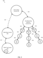
- FIG. 1 is a simplified diagram of a computer-assisted system 100 according to some embodiments.
- computer-assisted system 100 includes a device 110 with one or more movable or articulated arms 120.
- Each of the one or more articulated arms 120 supports one or more end effectors.
- device 110 may be consistent with a computer-assisted surgical device.
- the one or more articulated arms 120 each provides support for one or more instruments, surgical instruments, imaging devices, and/or the like mounted to a distal end of at least one of the articulated arms 120.
- Device 110 may further be coupled to an operator workstation (not shown), which may include one or more master controls for operating the device 110, the one or more articulated arms 120, and/or the end effectors.
- device 110 and the operator workstation may correspond to a da Vinci ® Surgical System commercialized by Intuitive Surgical, Inc. of Sunnyvale, California.
- computer-assisted surgical devices with other configurations, fewer or more articulated arms, and/or the like may optionally be used with computer-assisted system 100.
- Control unit 130 includes a processor 140 coupled to memory 150. Operation of control unit 130 is controlled by processor 140. And although control unit 130 is shown with only one processor 140, it is understood that processor 140 may be representative of one or more central processing units, multi-core processors, microprocessors, microcontrollers, digital signal processors, field programmable gate arrays (FPGAs), application specific integrated circuits (ASICs), and/or the like in control unit 130.
- processor 140 may be representative of one or more central processing units, multi-core processors, microprocessors, microcontrollers, digital signal processors, field programmable gate arrays (FPGAs), application specific integrated circuits (ASICs), and/or the like in control unit 130.
- Control unit 130 may be implemented as a stand-alone subsystem and/or board added to a computing device or as a virtual machine. In some embodiments, control unit may be included as part of the operator workstation and/or operated separately from, but in coordination with the operator workstation.
- Memory 150 is used to store software executed by control unit 130 and/or one or more data structures used during operation of control unit 130.
- Memory 150 may include one or more types of machine readable media. Some common forms of machine readable media may include floppy disk, flexible disk, hard disk, magnetic tape, any other magnetic medium, CD-ROM, any other optical medium, punch cards, paper tape, any other physical medium with patterns of holes, RAM, PROM, EPROM, FLASH-EPROM, any other memory chip or cartridge, and/or any other medium from which a processor or computer is adapted to read.
- memory 150 includes a motion control application 160 that supports autonomous and/or semiautonomous control of device 110.
- Motion control application 160 may include one or more application programming interfaces (APIs) for receiving position, motion, and/or other sensor information from device 110, exchanging position, motion, and/or collision avoidance information with other control units regarding other devices, such as a surgical table and/or imaging device, and/or planning and/or assisting in the planning of motion for device 110, articulated arms 120, and/or the end effectors of device 110.
- APIs application programming interfaces
- motion control application 160 is depicted as a software application, motion control application 160 may be implemented using hardware, software, and/or a combination of hardware and software.
- computer-assisted system 100 may be found in an operating room and/or an interventional suite. And although computer-assisted system 100 includes only one device 110 with two articulated arms 120, one of ordinary skill would understand that computer-assisted system 100 may include any number of devices with articulated arms and/or end effectors of similar and/or different design from device 110. In some examples, each of the devices may include fewer or more articulated arms and/or end effectors.
- Computer-assisted system 100 further includes a surgical table 170.
- surgical table 170 supports articulated movement of a table top 180 relative to a base of surgical table 170.
- the articulated movement of table top 180 may include support for changing a height, a tilt, a slide, a Trendelenburg orientation, and/or the like of table top 180.
- surgical table 170 may include one or more control inputs, such as a surgical table command unit for controlling the position and/or orientation of table top 180.
- surgical table 170 may correspond to one or more of the surgical tables commercialized by Trumpf Medical Systems GmbH of Germany.
- Surgical table 170 is also coupled to control unit 130 via a corresponding interface.
- the interface may include one or more wireless links, cables, connectors, and/or buses and may further include one or more networks with one or more network switching and/or routing devices.
- surgical table 170 may be coupled to a different control unit than control unit 130.
- motion control application 160 may include one or more application programming interfaces (APIs) for receiving position, motion, and/or other sensor information associated with surgical table 170 and/or table top 180.
- APIs application programming interfaces
- motion control application 160 may plan and/or assist in the planning of motion for surgical table 170 and/or table top 180.
- motion control application 160 may contribute to motion plans associated with collision avoidance, adapting to and/or avoid range of motion limits in joints and links, movement of articulated arms, instruments, end effectors, surgical table components, and/or the like to compensate for other motion in the articulated arms, instruments, end effectors, surgical table components, and/or the like, adjust a viewing device such as an endoscope to maintain and/or place an area of interest and/or one or more instruments or end effectors within a field of view of the viewing device.
- motion control application 160 may prevent motion of surgical table 170 and/or table top 180, such as by preventing movement of surgical table 170 and/or table top 180 through use of the surgical table command unit.
- motion control application 160 may help register device 110 with surgical table 170 so that a geometric relationship between device 110 and surgical table 170 is known.
- the geometric relationship may include a translation and/or one or more rotations between coordinate frames maintained for device 110 and surgical table 170.
- FIG. 2 is a simplified diagram showing a computer-assisted system 200 according to some embodiments.
- the computer-assisted system 200 may be consistent with computer-assisted system 100.
- the computer-assisted system 200 includes a computer-assisted device 210 with one or more articulated arms and a surgical table 280.
- the computer-assisted device 210 and the surgical table 280 are coupled together using one or more interfaces and one or more control units so that at least kinematic information about the surgical table 280 is known to the motion control application being used to perform motion of the articulated arms of the computer-assisted device 210.
- the computer-assisted device 210 includes various links and joints.
- the computer-assisted device is generally divided into three different sets of links and joints.
- a set-up structure 220 Starting at the proximal end with a mobile or patient-side cart 215 is a set-up structure 220.
- a series of links and set-up joints 240 forming an articulated arm.
- a multi-jointed manipulator 260 coupled to a distal end of the set-up joints 240.
- the series of set-up joints 240 and manipulator 260 may correspond to one of the articulated arms 120.
- the computer-assisted device is shown with only one series of set-up joints 240 and a corresponding manipulator 260, one of ordinary skill would understand that the computer-assisted device may include more than one series of set-up joints 240 and corresponding manipulators 260 so that the computer-assisted device is equipped with multiple articulated arms.
- the computer-assisted device 210 is mounted on the mobile cart 215.
- the mobile cart 215 enables the computer-assisted device 210 to be transported from location to location, such as between operating rooms or within an operating room to better position the computer-assisted device in proximity to the surgical table 180.
- the set-up structure 220 is mounted on the mobile cart 215.
- the set-up structure 220 includes a two part column including column links 221 and 222. Coupled to the upper or distal end of the column link 222 is a shoulder joint 223. Coupled to the shoulder joint 223 is a two-part boom including boom links 224 and 225. At the distal end of the boom link 225 is a wrist joint 226, and coupled to the wrist joint 226 is an arm mounting platform 227.
- the links and joints of the set-up structure 220 include various degrees of freedom for changing the position and orientation (i.e., the pose) of the arm mounting platform 227.
- the two-part column is used to adjust a height of the arm mounting platform 227 by moving the shoulder joint 223 up and down along an axis 232.
- the arm mounting platform 227 is additionally rotated about the mobile cart 215, the two-part column, and the axis 232 using the shoulder joint 223.
- the horizontal position of the arm mounting platform 227 is adjusted along an axis 234 using the two-part boom.
- the orientation of the arm mounting platform 227 may also adjusted by rotation about an arm mounting platform orientation axis 236 using the wrist joint 226.
- the position of the arm mounting platform 227 may be adjusted vertically above the mobile cart 215 using the two-part column.
- the positions of the arm mounting platform 227 may also be adjusted radially and angularly about the mobile cart 215 using the two-part boom and the shoulder joint 223, respectively.
- the angular orientation of the arm mounting platform 227 may also be changed using the wrist joint 226.
- the arm mounting platform 227 is used as a mounting point for one or more articulated arms.
- the ability to adjust the height, horizontal position, and orientation of the arm mounting platform 227 about the mobile cart 215 provides a flexible set-up structure for positioning and orienting the one or more articulated arms about a work space located near the mobile cart 215 where an operation or procedure is to take place.
- arm mounting platform 227 may be positioned above a patient so that the various articulated arms and their corresponding manipulators and instruments have sufficient range of motion to perform a surgical procedure on the patient.
- Figure 2 shows a single articulated arm coupled to the arm mounting platform 227 using a first set-up joint 242. And although only one articulated arm is shown, one of ordinary skill would understand that multiple articulated arms may be coupled to the arm mounting platform 227 using additional first set-up joints.
- the first set-up joint 242 forms the most proximal portion of the set-up joints 240 section of the articulated arm.
- the set-up joints 240 may further include a series of joints and links. As shown in Figure 2 , the set-up joints 240 include at least links 244 and 246 coupled via one or more joints (not expressly shown).
- the joints and links of the set-up joints 240 include the ability to rotate the set-up joints 240 relative to the arm mounting platform 227 about an axis 252 using the first set-up joint 242, adjust a radial or horizontal distance between the first set-up joint 242 and the link 246, adjust a height of a manipulator mount 262 at the distal end of link 246 relative to the arm mounting platform 227 along an axis 254, and rotate the manipulator mount 262 about axis 254.
- the set-up joints 240 may further include additional joints, links, and axes permitting additional degrees of freedom for altering a pose of the manipulator mount 262 relative to the arm mounting platform 227.
- the manipulator 260 is coupled to the distal end of the set-up joints 240 via the manipulator mount 262.
- the manipulator 260 includes additional joints 264 and links 266 with an instrument carriage 268 mounted at the distal end of the manipulator 260.
- An instrument 270 is mounted to the instrument carriage 268.
- Instrument 270 includes a shaft 272, which is aligned along an insertion axis.
- the shaft 272 is typically aligned so that it passes through a remote center of motion 274 associated with the manipulator 260.
- Location of the remote center of motion 274 is typically maintained in a fixed translational relationship relative to the manipulator mount 262 so that operation of the joints 264 in the manipulator 260 result in rotations of the shaft 272 about the remote center of motion 274.
- the fixed translational relationship of the remote center of motion 274 relative to the manipulator mount 262 is maintained using physical constraints in the joints 264 and links 266 of the manipulator 260, using software constraints placed on the motions permitted for the joints 264, and/or a combination of both.
- Representative embodiments of computer-assisted surgical devices using remote centers of motion maintained using physical constraints in joints and links are described in U.S. Patent Application No. 13/906,888 entitled "Redundant Axis and Degree of Freedom for Hardware-Constrained Remote Center Robotic Manipulator," which was filed May 13, 2013 , and published as US 2013/0325031 and representative embodiments of computer-assisted surgical devices using remote centers of motion maintained by software constraints are described in U.S. Patent No.
- the remote center of motion 274 may correspond to a location of a body opening, such as an incision site or body orifice, in a patient 278 where shaft 272 is inserted into the patient 278. Because the remote center of motion 274 corresponds to the body opening, as the instrument 270 is used, the remote center of motion 274 remains stationary relative to the patient 278 to limit stresses on the anatomy of the patient 278 at the remote center of motion 274.
- the shaft 272 may be optionally passed through a cannula (not shown) located at the body opening.
- instruments having a relatively larger shaft or guide tube outer diameter may be passed through the body opening using a cannula and the cannula may optionally be omitted for instruments having a relatively smaller shaft or guide tube outer diameter (e.g., 2-3 mm or less).
- the degrees of freedom in the manipulator 260 due to the joints 264 and the links 266 may permit at least control of the roll, pitch, and yaw of the shaft 272 and/or the end effector 276 relative to the manipulator mount 262.
- the degrees of freedom in the manipulator 260 may further include the ability to advance and/or withdraw the shaft 272 using the instrument carriage 268 so that the end effector 276 may be advanced and/or withdrawn along the insertion axis and relative to the remote center of motion 274.
- the manipulator 260 may be consistent with manipulators for use with the da Vinci ® Surgical System commercialized by Intuitive Surgical, Inc. of Sunnyvale, California.
- the instrument 270 may be an imaging device such as an endoscope, a gripper, a surgical instrument such as a cautery or a scalpel, and/or the like.
- the end effector 276 may include additional degrees of freedom, such as roll, pitch, yaw, grip, and/or the like that allow for additional localized manipulation of portions of the end effector 276 relative to the distal end of the shaft 272.
- the surgical table 280 includes a table base 282 and a table top 284, with the table base 282 being located in proximity to mobile cart 215 so that the instrument 270 and/or end effector 276 may be manipulated by the computer-assisted device 210 while the shaft 272 of instrument 270 is inserted into the patient 278 at the body opening.
- the surgical table 280 further includes an articulated structure 290 that includes one or more joints or links between the table base 282 and the table top 284 so that the relative location of the table top 284, and thus the patient 278, relative to the table base 280 is controlled.
- the articulated structure 290 may be configured so that the table top 284 is controlled relative to a virtually-defined table motion isocenter 286 that may be located at a point above the table top 284.
- isocenter 286 may be located within the interior of the patient 278.
- isocenter 286 may be collocated with the body wall of the patient at or near one of the body openings, such as a body opening site corresponding to remote center of motion 274.
- the articulated structure 290 includes a height adjustment joint 292 so that the table top 284 may be raised and/or lowered relative to the table base 282.
- the articulated structure 290 further includes joints and links to change both the tilt 294 and Trendelenburg 296 orientation of the table top 284 relative to the isocenter 286.
- the tilt 294 allows the table top 284 to be tilted side-to-side so that either the right or left side of the patient 278 is rotated upward relative to the other side of the patient 278 (i.e., about a longitudinal or head-to-toe (cranial-caudal) axis of the table top 284).
- the Trendelenburg 296 allows the table top 284 to be rotated so that either the feet of the patient 278 are raised (Trendelenburg) or the head of the patient 278 is raised (reverse Trendelenburg). In some examples, either the tilt 294 and/or the Trendelenburg 296 rotations may be adjusted to generate rotations about isocenter 286.
- the articulated structure 290 further includes additional links and joints 298 to slide the table top 284 along the longitudinal (cranial-caudal) axis relative to the table base 282 with generally a left and/or right motion as depicted in Figure 2 .
- FIGS 8A-8G are simplified schematic views that illustrate various computer-assisted device system architectures that incorporate the integrated computer-assisted device and movable surgical table features described herein.
- the various illustrated system components are in accordance with the principles described herein. In these illustrations, the components are simplified for clarity, and various details such as individual links, joints, manipulators, instruments, end effectors, etc. are not shown, but they should be understood to be incorporated in the various illustrated components.
- cannulas associated with one or more surgical instruments or clusters of instruments are not shown, and it should be understood that cannulas and other instrument guide devices optionally may be used for instruments or instrument clusters having a relatively larger shaft or guide tube outer diameter (e.g., 4-5 mm or more) and optionally may be omitted for instruments having a relatively smaller shaft or guide tube outer diameter (e.g., 2-3 mm or less).
- cannulas and other instrument guide devices optionally may be used for instruments or instrument clusters having a relatively larger shaft or guide tube outer diameter (e.g., 4-5 mm or more) and optionally may be omitted for instruments having a relatively smaller shaft or guide tube outer diameter (e.g., 2-3 mm or less).
- teleoperated manipulators should be understood to include manipulators that during surgery define a remote center of motion by using hardware constraints (e.g., fixed intersecting instrument pitch, yaw, and roll axes) or software constraints (e.g., software-constrained intersecting instrument pitch, yaw, and roll axes).
- hardware constraints e.g., fixed intersecting instrument pitch, yaw, and roll axes
- software constraints e.g., software-constrained intersecting instrument pitch, yaw, and roll axes
- a hybrid of such instrument axes of rotation may be defined (e.g., hardware-constrained roll axis and software-constrained pitch and yaw axes) are also possible.
- some manipulators may not define and constrain any surgical instrument axes of rotation during a procedure, and some manipulators may define and constrain only one or two instrument axes of rotation during a procedure.
- Figure 8A illustrates a movable surgical table 1100 and a single-instrument computer-assisted device 1101a are shown.
- Surgical table 1100 includes a movable table top 1102 and a table support structure 1103 that extends from a mechanically grounded proximal base 1104 to support the table top 1102 at a distal end.
- surgical table 1100 may be consistent with surgical table 170 and/or 280.
- Computer-assisted device 1101a includes a teleoperated manipulator and a single instrument assembly 1105a.
- Computer-assisted device 1101a also includes a support structure 1106a that is mechanically grounded at a proximal base 1107a and that extends to support manipulator and instrument assembly 1105a at a distal end.
- Support structure 1106a is configured to allow assembly 1105 a to be moved and held in various fixed poses with reference to surgical table 1100.
- Base 1107a is optionally permanently fixed or movable with reference to surgical table 1100.
- Surgical table 1100 and computer-assisted device 1101a operate together as described herein.
- Figure 8A further shows an optional second computer-assisted device 1101b, which illustrates that two, three, four, five, or more individual computer-assisted devices may be included, each having a corresponding individual teleoperated manipulator and single-instrument assembly(ies) 1105b supported by a corresponding support structure 1106b.
- Computer-assisted device 1101b is mechanically grounded, and assemblies 1105b are posed, similarly to computer-assisted device 1101a.
- Surgical table 1100 and computer-assisted devices 1101a and 1101b together make a multi-instrument surgical system, and they operate together as described herein.
- computer-assisted devices 1101a and/or 1101b may be consistent with computer-assisted devices 110 and/or 210.
- Computer-assisted device 1111 is a multi-instrument device that includes two, three, four, five, or more individual teleoperated manipulator and single-instrument assemblies as shown by representative manipulator and instrument assemblies 1105a and 1105b.
- the assemblies 1105a and 1 105b of computer-assisted device 1111 are supported by a combined support structure 1112, which allows assemblies 1105a and 1105b to be moved and posed together as a group with reference to surgical table 1100.
- the assemblies 1105a and 1105b of computer-assisted device 1111 are also each supported by a corresponding individual support structure 1113a and 1113b, respectively, which allows each assembly 1105a and 1105b to be individually moved and posed with reference to surgical table 1100 and to the one or more other assemblies 1105a and 1105b.
- Examples of such a multi-instrument surgical system architecture are the da Vinci Si ® Surgical System and the da Vinci ® Xi TM Surgical System, commercialized by Intuitive Surgical, Inc.
- Surgical table 1100 and surgical manipulator system 1111 operate together as described herein.
- computer-assisted device 1111 is consistent with computer-assisted devices 110 and/or 210.
- the computer-assisted devices of Figures 8A and 8B are each shown mechanically grounded at the floor. But, one or more such computer-assisted devices may optionally be mechanically grounded at a wall or ceiling and be permanently fixed or movable with reference to such a wall or ceiling ground. In some examples, computer-assisted devices may be mounted to the wall or ceiling using a track or grid system that allows the support base of the computer-assisted systems to be moved relative to the surgical table. In some examples, one or more fixed or releasable mounting clamps may be used to mount the respective support bases to the track or grid system. As shown in Figure 8C , a computer-assisted device 1121a is mechanically grounded at a wall, and a computer-assisted device 1121b is mechanically grounded at a ceiling.
- computer-assisted devices may be indirectly mechanically grounded via the movable surgical table 1100.
- a computer-assisted device 1131a is coupled to the table top 1102 of surgical table 1100.
- Computer-assisted device 1131a may optionally be coupled to other portions of surgical table 1100, such as table support structure 1103 or table base 1104, as indicated by the dashed structures shown in Figure 8D .
- table top 1102 moves with reference to table support structure 1103 or table base 1104
- the computer-assisted device 1131 a likewise moves with reference to table support structure 1103 or table base 1104.
- Figure 8D also shows that a second computer-assisted device 1131 b optionally may be added, configured similarly to computer-assisted device 1131a to create a multi-instrument system.
- Systems that include one or more computer-assisted device coupled to the surgical table operate as disclosed herein.
- a system may include one computer-assisted device mechanically grounded at the floor, and a second computer-assisted device mechanically grounded to the floor via the surgical table.
- Such hybrid mechanical ground systems operate as disclosed herein.
- Inventive aspects also include single-body opening systems in which two or more surgical instruments enter the body via a single body opening. Examples of such systems are shown in U.S. Patent No. 8,852,208 entitled “Surgical System Instrument Mounting,” which was filed August 12, 2010 , and U.S. Patent No. 9,060,678 entitled “Minimally Invasive Surgical System,” which was filed June 13, 2007 .
- Figure 8E illustrates a teleoperated multi-instrument computer-assisted device 1141 together with surgical table 1100 as described above. Two or more instruments 1142 are each coupled to a corresponding manipulator 1143 and the cluster of instruments 1142 and instrument manipulators 1143 are moved together by a system manipulator 1144.
- the system manipulator 1144 is supported by a support assembly 1145 that allows system manipulator 1144 to be moved to and fixed at various poses.
- Support assembly 1145 is mechanically grounded at a base 1146 consistent with the descriptions above.
- the two or more instruments 1142 are inserted into the patient at the single body opening.
- the instruments 1142 extend together through a single guide tube, and the guide tube optionally extends through a cannula, as described in the references cited above.
- Computer-assisted device 1141 and surgical table 1100 operate together as described herein.
- Figure 8F illustrates another multi-instrument, single-body opening computer-assisted device 1151 mechanically grounded via the surgical table 1100, optionally by being coupled to table top 1102, table support structure 1103, or table base 1104.
- the descriptions above with reference to Figure 8D also applies to the mechanical grounding options illustrated in Figure 8F .
- Computer-assisted device 1151 and surgical table 1100 work together as described herein.
- Figure 8G illustrates that one or more teleoperated multi-instrument, single-body opening computer-assisted devices 1161 and one or more teleoperated single-instrument computer-assisted devices 1162 may be combined to operate with surgical table 1100 as described herein.
- Each of the computer-assisted devices 1161 and 1162 may be mechanically grounded, directly or via another structure, in various ways as described above.
- FIG 3 is a simplified diagram of a kinematic model 300 of a computer-assisted medical system according to some embodiments.
- kinematic model 300 may include kinematic information associated with many sources and/or devices.
- the kinematic information is based on known kinematic models for the links and joints of a computer-assisted medical device and a surgical table.
- the kinematic information is further based on information associated with the position and/or orientation of the joints of the computer-assisted medical device and the surgical table.
- the information associated with the position and/or orientation of the joints may be derived from one or more sensors, such as encoders, measuring the linear positions of prismatic joints and the rotational positions of revolute joints.
- the kinematic model 300 includes several coordinate frames or coordinate systems and transformations, such as homogeneous transforms, for transforming positions and/or orientation from one of the coordinate frames to another of the coordinate frames.
- the kinematic model 300 may be used to permit the forward and/or reverse mapping of positions and/or orientations in one of the coordinate frames in any other of the coordinate frames by composing the forward and/or reverse/inverse transforms noted by the transform linkages included in Figure 3 .
- the transforms when the transforms are modeled as homogenous transforms in matrix form, the composing is accomplished using matrix multiplication.
- the kinematic model 300 may be used to model the kinematic relationships of the computer-assisted device 210 and the surgical table 280 of Figure 2 .
- the kinematic model 300 includes a table base coordinate frame 305 that is used to model a position and/or orientation of a surgical table, such as surgical table 170 and/or surgical table 280.
- the table base coordinate frame 305 may be used to model other points on the surgical table relative to a reference point and/or orientation associated with the surgical table.
- the reference point and/or orientation may be associated with a table base of the surgical table, such as the table base 282.
- the table base coordinate frame 305 may be suitable for use as a world coordinate frame for the computer-assisted system.
- the kinematic model 300 further includes a table top coordinate frame 310 that may be used to model positions and/or orientations in a coordinate frame representative of a table top of the surgical table, such as the table top 284.
- the table top coordinate frame 310 may be centered about a rotational center or isocenter of the table top, such as isocenter 286.
- the z-axis of the table top coordinate frame 310 may be oriented vertically with respect to a floor or surface on which the surgical table is placed and/or orthogonal to the surface of the table top.
- the x- and y-axes of the table top coordinate frame 310 may be oriented to capture the longitudinal (head to toe) and lateral (side-to-side) major axes of the table top.
- a table base to table top coordinate transform 315 is used to map positions and/or orientations between the table top coordinate frame 310 and the table base coordinate frame 305.
- one or more kinematic models of an articulated structure of the surgical table, such as articulated structure 290, along with past and/or current joint sensor readings is used to determine the table base to table top coordinate transform 315.
- the table base to table top coordinate transform 315 models the composite effect of the height, tilt, Trendelenburg, and/or slide settings associated with the surgical table.
- the kinematic model 300 further includes a device base coordinate frame that is used to model a position and/or orientation of a computer-assisted device, such as computer-assisted device 110 and/or computer-assisted device 210.
- the device base coordinate frame 320 may be used to model other points on the computer-assisted device relative to a reference point and/or orientation associated with the computer-assisted device.
- the reference point and/or orientation may be associated with a device base of the computer-assisted device, such as the mobile cart 215.
- the device base coordinate frame 320 may be suitable for use as the world coordinate frame for the computer-assisted system.
- the registration may be used to determine a registration transform 325 between the table top coordinate frame 310 and the device base coordinate from 320.
- the registration transform 325 may be a partial or full transform between the table top coordinate frame 310 and the device base coordinate frame 320.
- the registration transform 325 is determined based on the architectural arrangements between the surgical table and the computer-assisted device.
- the registration transform 325 is determined from the table base to table top coordinate transform 315 and knowing where the computer-assisted device is mounted to the table top 112.
- determination of the registration transform 325 is simplified by placing some restrictions on the device base coordinate frame 320 and the table base coordinate frame 305.
- these restrictions include that both the device base coordinate frame 320 and the table base coordinate frame 305 agree on the same vertical up or z-axis.
- the relative orientations of the walls of the room (e.g., perpendicular to the floor) and the ceiling (e.g., parallel to the floor) are known it is possible for a common vertical up or z axis (or a suitable orientation transform) to be maintained for both the device base coordinate frame 320 and the table base coordinate frame 305 or a suitable orientation transform.
- the registration transform 325 may optionally model just the rotational relationship of the device base to the table base about the z-axis of the table base coordinate frame 305 (e.g., a ⁇ Z registration).
- the registration transform 325 may optionally also model a horizontal offset between the table base coordinate frame 305 and the device base coordinate frame 320 (e.g., a XY registration). This is possible because the vertical (z) relationship between the computer-assisted device and the surgical table are known. Thus, changes in a height of the table top in the table base to table top transform 315 are analogous to vertical adjustments in the device base coordinate frame 320 because the vertical axes in the table base coordinate frame 305 and the device base coordinate frame 320 are the same or nearly the same so that changes in height between the table base coordinate frame 305 and the device base coordinate frame 320 are within a reasonable tolerance of each other.
- a horizontal offset between the table base coordinate frame 305 and the device base coordinate frame 320 e.g., a XY registration
- the tilt and Trendelenburg adjustments in the table base to table top transform 315 may be mapped to the device base coordinate frame 320 by knowing the height of the table top (or its isocenter) and the ⁇ Z and/or XY registration.
- the registration transform 325 and the table base to table top transform 315 may be used to model the computer-assisted surgical device as if it were attached to the table top even when this is architecturally not the case.
- the kinematic model 300 further includes an arm mounting platform coordinate frame 330 that is used as a suitable model for a shared coordinate frame associated with the most proximal points on the articulated arms of the computer-assisted device.
- the arm mounting platform coordinate frame 330 may be associated with and oriented relative to a convenient point on an arm mounting platform, such as the arm mounting platform 227.
- the center point of the arm mounting platform coordinate frame 330 may be located on the arm mounting platform orientation axis 236 with the z-axis of the arm mounting platform coordinate frame 330 being aligned with arm mounting platform orientation axis 236.
- a device base to arm mounting platform coordinate transform 335 is used to map positions and/or orientations between the device base coordinate frame 320 and the arm mounting platform coordinate frame 330.
- one or more kinematic models of the links and joints of the computer-assisted device between the device base and the arm mounting platform, such as the set-up structure 220, along with past and/or current joint sensor readings are used to determine the device base to arm mounting platform coordinate transform 335.
- the device base to arm mounting platform coordinate transform 335 may model the composite effect of the two-part column, shoulder joint, two-part boom, and wrist joint of the setup structure portion of the computer-assisted device.
- the kinematic model 300 further includes a series of coordinate frames and transforms associated with each of the articulated arms of the computer-assisted device. As shown in Figure 3 , the kinematic model 300 includes coordinate frames and transforms for three articulated arms, although one of ordinary skill would understand that different computer-assisted devices may include fewer and/or more articulated arms (e.g., one, two, four, five, or more). Consistent with the configuration of the links and joints of the computer-assisted device 210 of Figure 2 , each of the articulated arms is modeled using a manipulator mount coordinate frame, a remote center of motion coordinate frame, and an instrument or camera coordinate frame, depending on a type of instrument mounted to the distal end of the articulated arm.
- the kinematic relationships of a first one of the articulated arms is captured using a manipulator mount coordinate frame 341, a remote center of motion coordinate frame 342, an instrument coordinate frame 343, an arm mounting platform to manipulator mount transform 344, a manipulator mount to remote center of motion transform 345, and a remote center of motion to instrument transform 346.
- the manipulator mount coordinate frame 341 represents a suitable model for representing positions and/or orientations associated with a manipulator, such as manipulator 260.
- the manipulator mount coordinate frame 341 is associated with a manipulator mount, such as the manipulator mount 262 of the corresponding articulated arm.
- the arm mounting platform to manipulator mount transform 344 is then based on one or more kinematic models of the links and joints of the computer-assisted device between the arm mounting platform and the corresponding manipulator mount, such as the corresponding set-up joints 240, along with past and/or current joint sensor readings of the corresponding set-up joints 240.
- the remote center of motion coordinate frame 342 is associated with a remote center of motion of the instrument mounted on the manipulator, such as the corresponding remote center of motion 274 of the corresponding manipulator 260.
- the manipulator mount to remote center of motion transform 345 is then based on one or more kinematic models of the links and joints of the computer-assisted device between the corresponding manipulator mount and the corresponding remote center of motion, such as the corresponding joints 264, corresponding links 266, and corresponding carriage 268 of the corresponding manipulator 260, along with past and/or current joint sensor readings of the corresponding joints 264.
- the manipulator mount to remote center of motion transform 345 includes an essentially static translational component that does not change as the manipulator and instrument are operated and a dynamic rotational component that changes as the manipulator and instrument are operated.
- the instrument coordinate frame 343 is associated with an end effector located at the distal end of the instrument, such as the corresponding end effector 276.
- the remote center of motion to instrument transform 346 is then based on one or more kinematic models of the links and joints of the computer-assisted device that move and/or orient the corresponding instrument, end effector, and remote center of motion, along with past and/or current joint sensor readings.
- the remote center of motion to instrument transform 346 accounts for the orientation at which the shaft, such as the corresponding shaft 272, passes through the remote center of motion and the distance to which the shaft is advanced and/or withdrawn relative to the remote center of motion.
- the remote center of motion to instrument transform 346 may be constrained to reflect that the insertion axis of the shaft of the instrument passes through the remote center of motion and accounts for rotations of the shaft and the end effector about the axis defined by the shaft.
- the kinematic relationships of a second one of the articulated arms is captured using a manipulator mount coordinate frame 351, a remote center of motion coordinate frame 352, an instrument coordinate frame 353, an arm mounting platform to manipulator mount transform 354, a manipulator mount to remote center of motion transform 355, and a remote center of motion to instrument transform 356.
- the manipulator mount coordinate frame 351 represents a suitable model for representing positions and/or orientations associated with a manipulator, such as manipulator 260.
- the manipulator mount coordinate frame 351 is associated with a manipulator mount, such as the manipulator mount 262 of the corresponding articulated arm.
- the arm mounting platform to manipulator mount transform 354 is then based on one or more kinematic models of the links and joints of the computer-assisted device between the arm mounting platform and the corresponding manipulator mount, such as the corresponding set-up joints 240, along with past and/or current joint sensor readings of the corresponding set-up joints 240.
- the remote center of motion coordinate frame 352 is associated with a remote center of motion of the manipulator mounted on the articulated arm, such as the corresponding remote center of motion 274 of the corresponding manipulator 260.
- the manipulator mount to remote center of motion transform 355 is then based on one or more kinematic models of the links and joints of the computer-assisted device between the corresponding manipulator mount and the corresponding remote center of motion, such as the corresponding joints 264, corresponding links 266, and corresponding carriage 268 of the corresponding manipulator 260, along with past and/or current joint sensor readings of the corresponding joints 264.
- the mount to remote center of motion transform 355 includes an essentially static translational component that does not change as the manipulator and instrument are operated and a dynamic rotational component that changes as the manipulator and instrument are operated.
- the instrument coordinate frame 353 is associated with an end effector located at the distal end of the instrument, such as the corresponding instrument 270 and/or end effector 276.
- the remote center of motion to instrument transform 356 is then based on one or more kinematic models of the links and joints of the computer-assisted device that move and/or orient the corresponding instrument, end effector, and remote center of motion, along with past and/or current joint sensor readings.
- the remote center of motion to instrument transform 356 accounts for the orientation at which the shaft, such as the corresponding shaft 272, passes through the remote center of motion and the distance to which the shaft is advanced and/or withdrawn relative to the remote center of motion.
- the remote center of motion to instrument transform 356 may be constrained to reflect that the insertion axis of the shaft of the instrument passes through the remote center of motion and accounts for rotations of the shaft and the end effector about the insertion axis defined by the shaft.
- the kinematic relationships of a third one of the articulated arms is captured using a manipulator mount coordinate frame 361, a remote center of motion coordinate frame 362, a camera coordinate frame 363, an arm mounting platform to manipulator mount transform 364, a manipulator mount to remote center of motion transform 365, and a remote center of motion to camera transform 366.
- the manipulator mount coordinate frame 361 represents a suitable model for representing positions and/or orientations associated with a manipulator, such as manipulator 260.
- the manipulator mount coordinate frame 361 is associated with a manipulator mount, such as the manipulator mount 262 of the corresponding articulated arm.
- the arm mounting platform to manipulator mount transform 364 is then based on one or more kinematic models of the links and joints of the computer-assisted device between the arm mounting platform and the corresponding manipulator mount, such as the corresponding set-up joints 240, along with past and/or current joint sensor readings of the corresponding set-up joints 240.
- the remote center of motion coordinate frame 362 is associated with a remote center of motion of the manipulator mounted on the articulated arm, such as the corresponding remote center of motion 274 of the corresponding manipulator 260.
- the manipulator mount to remote center of motion transform 365 is then based on one or more kinematic models of the links and joints of the computer-assisted device between the corresponding manipulator mount and the corresponding remote center of motion, such as the corresponding joints 264, corresponding links 266, and corresponding carriage 268 of the corresponding manipulator 260, along with past and/or current joint sensor readings of the corresponding joints 264.
- the mount to remote center of motion transform 365 includes an essentially static translational component that does not change as the manipulator and instrument are operated and a dynamic rotational component that changes as the manipulator and instrument are operated.
- the camera coordinate frame 363 is associated with an imaging device, such an endoscope, mounted on the articulated arm.
- the remote center of motion to camera transform 366 is then based on one or more kinematic models of the links and joints of the computer-assisted device that move and/or orient the imaging device and the corresponding remote center of motion, along with past and/or current joint sensor readings.
- the remote center of motion to camera transform 366 accounts for the orientation at which the shaft, such as the corresponding shaft 272, passes through the remote center of motion and the distance to which the shaft is advanced and/or withdrawn relative to the remote center of motion.
- the remote center of motion to camera transform 366 may be constrained to reflect that the insertion axis of the shaft of the imaging device passes through the remote center of motion and accounts for rotations of the imaging device about the axis defined by the shaft.
- the registration between the surgical table and the computer-assisted device may be determined between the table top coordinate frame 310 and the device base coordinate frame 320 using an alternative registration transform.
- registration transform 325 is determined by composing the alternative registration transform with the inverse/reverse of the table base to table top transform 315.
- the coordinate frames and/or transforms used to model the computer-assisted device may be arranged differently dependent on the particular configuration of the links and joints of the computer-assisted device, its articulated arms, its end effectors, its manipulators, and/or its instruments.
- the coordinate frames and transforms of the kinematic model 300 may be used to model coordinate frames and transforms associated with one or more virtual instruments and/or virtual cameras.
- the virtual instruments and/or cameras may be associated with previously stored and/or latched instrument positions, projections of instruments and/or cameras due to a motion, reference points defined by a surgeon and/or other personnel, and/or the like.
- this may allow for a less time-consuming procedure as surgical table motion may occur without first having to remove the manipulator-controlled surgical instruments from the patient and undock the manipulators from the cannulas that stay inserted in the patient.. In some examples, this allows a surgeon and/or other medical personnel to monitor organ movement while the surgical table motion is occurring to obtain a more optimal surgical table pose. In some examples, this may also permit active continuation of a surgical procedure during surgical table motion.
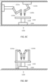
- FIGS 4A and 4B are simplified diagrams of relationships between a surgical table 410 and a computer-assisted device 420 according to some embodiments.
- surgical table 410 may be consistent with surgical table 170 and/or 280 and computer-assisted device may be consistent with computer-assisted device 110, 210, and/or any of the computer-assisted devices of Figures 8A-8G .
- a patient 430 is placed on surgical table 410.
- any movement in surgical table 410 results in corresponding movement in the one or more portions of the anatomy of patient 430.
- this assumption is somewhat inaccurate, as is discussed in further detail below, by monitoring movements of the top of surgical table 410 in a surgical table coordinate frame and movements of the anatomy of patient 430 in a computer-assisted device coordinate frame, it is possible to determine approximate estimates of the geometric relationship between surgical table 410 and computer-assisted device 420.
- the geometric relationship between surgical table 410 and computer-assisted device 420 may be characterized as determining a horizontal offset and an angular rotation about the vertical up or z axis between surgical table 410 and computer-assisted device 420. This is possible because when table base coordinate frame 440 and device base coordinate frame 450 agree on the z axis, the differences in z coordinate values between table base coordinate frame 440 and device base coordinate frame 450 are already known.
- table base coordinate frame 440 may correspond to table base coordinate frame 350 and/or device base coordinate frame 450 may correspond to device base coordinate frame 330.
- the xy plane of the table base coordinate frame 440 and the xy plane of the device base coordinate frame 450 are parallel.
- full registration between surgical table 410 and computer-assisted device 420 involves determining the horizontal offset, ⁇ XY , between the table base coordinate frame 440 and the device base coordinate frame 450, and the rotation about the z-axis, ⁇ Z , between the table base coordinate frame 440 and the device base coordinate frame 450.
- a full registration between surgical table 410 and computer-assisted device 420 may not be needed for operations that involve relative motions between surgical table 410 and computer-assisted device 420, because translations in the table base coordinate frame 440 may be mapped to translations in the device base coordinate frame 450 using ⁇ Z .
- rotations of the top of surgical table 410 relative to the table base coordinate frame 440 may be mapped to rotations in the device base coordinate frame 450 using ⁇ Z .
- a partial registration that determines ⁇ Z is often sufficient for most purposes.
- Figure 4B depicts how ⁇ Z may be determined by monitoring movement, ⁇ T , of the top of surgical table 410 in the table base coordinate frame 440 and movement, ⁇ D , of a control point of computer-assisted device 420, such as remote center of motion 274, in the device base coordinate frame 450.
- ⁇ T movement of surgical table 410
- ⁇ D movement of a control point of computer-assisted device 420
- the translational differences between the movement of surgical table 410 and computer-assisted device 420 have been removed as they do not affect the angular difference ⁇ Z between the two movements.
- the movement ⁇ T may occur as a result of a tilt, Trendelenburg, and/or slide adjustment of surgical table 410.
- ⁇ T and the magnitude of ⁇ D are not as important as knowing the relative directions of ⁇ T and ⁇ D in the xy planes of the table base coordinate frame 440 and the device base coordinate frame 450, respectively.
- a table base to table top transform such as the table base to table top transform 315, is used to determine an angular direction ⁇ T of the movement ⁇ T relative to the X T axis.
- one or more kinematic models of computer-assisted device 420 is used to determine an angular direction ⁇ D of a movement ⁇ D of a control point, such as a remote center of motion, relative to the X D axis.
- the difference between ⁇ D and ⁇ T represents the ⁇ Z between the table base coordinate frame 440 and the device base coordinate frame 450, which becomes the basis for the registration transform.
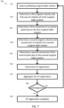
- Figure 5 is a simplified diagram of a method 500 of ⁇ Z registering a surgical table with a computer-assisted device according to some embodiments.
- One or more of the processes 510-580 of method 500 may be implemented, at least in part, in the form of executable code stored on non-transient, tangible, machine readable media that when run by one or more processors (e.g., the processor 140 in control unit 130) may cause the one or more processors to perform one or more of the processes 510-580.
- processors e.g., the processor 140 in control unit 130
- method 500 may be used to perform partial registration between the surgical table, such as surgical table 170, 280, and/or 410, and the computer-assisted device, such as computer-assisted device 110, 210, 420, and/or any of the computer-assisted devices of Figures 8A-8G .
- the partial registration may determine a ⁇ Z between a table base coordinate frame, such as table base coordinate frame 305 and/or 440, and a device base coordinate frame, such as device base coordinate frame 330 and/or 450.
- one or more of the processes 510, 570, and/or 580 are optional and may be omitted.
- the isocenter of the surgical table is lowered. Because the isocenter of a surgical table, such as isocenter 286, represents an artificially defined point about which at least Trendelenburg rotations occur, it is possible that it may be set at a height that is above one or more control points of the computer-assisted device that are used during method 500. When a control point is located below the isocenter of the surgical table, the movement of the control point is in the opposite direction to the movement of the table top causing an 180° phase shift in angular direction of the movement of the top of the surgical table as determined during process 530. To avoid this problem, the isocenter of the surgical table may be lowered during at least the early portions of the registration of method 500.
- the isocenter of the surgical table may optionally be lowered to a point at or below the top of the surgical table, such as to be coincident with the center of rotation for the tilt axis of the surgical table.
- the isocenter position of the surgical table prior to the lowering is saved for use during process 580.
- lowering the isocenter of the surgical table may also result in enhanced horizontal movement of the top of the table, which may improve the speed at which the registration process converges.
- qualifying motion of the surgical table is detected. Not all movement of a control point, such as a remote center of motion, of the computer-assisted device are suitable for use during the registration of method 500. In some examples, vertical movement of the surgical table, which does not generate any horizontal movement, does not provide suitable information for use during method 500. In some examples, there may be small oscillations in the horizontal movement of the control points that do not occur as a result of the surgical table movement.
- these small oscillations may occur as a result of autonomic motions of the patient (e.g., breathing, heartbeat, etc.), oscillations and/or vibrations in the articulated arms and/or manipulators of the computer-assisted device, changes in insufflation, and/or the like.
- registration may be limited to qualifying motions.
- a qualifying motion is a net horizontal motion in a control point that exceeds a threshold value determined based on likely oscillations that may occur.
- the threshold value is about 8 to 10 mm or so.
- the qualifying motion is detected by latching and/or storing an initial horizontal position of the control point and then periodically monitoring the actual horizontal position of the control point and waiting until a distance between the actual horizontal position and the initial horizontal position exceeds the threshold value. Once the qualifying motion is detected it is used as a basis for a registration estimate.
- a coherence check may also be used to determine whether the net horizontal motion is a qualifying motion.
- process 520 may record a sequence of incremental motions or vectors indicating the incremental change in the actual horizontal position of the control point between successive instances in which the actual horizontal position of the control point is monitored.
- each of the incremental motions may be longer than a predetermined length, such as 1 mm.
- each of the incremental motions may be a net motion of the control point over a predetermined length of time, such as 10 ms.
- the net horizontal motion is compared against a path of motion described by the incremental motions to determine whether the net horizontal motion is an accurate approximation of the incremental motions.
- the angular components of the incremental motions is compared to the angular components of the net horizontal motion to determine whether there is a consistent direction of motion.
- a length of the path is compared to a magnitude of the net horizontal motion to determine whether there is a consistent pattern of motion.
- a magnitude of a vector sum of the recorded vectors i.e., a magnitude of the net horizontal motion
- Equation 1 is used to perform the coherence test, where V i represents a respective instance of a recorded vector. ⁇ v ⁇ i ⁇ v ⁇ i ⁇ Configurable _ Threshold
- information about the surgical table motion is exchanged between the surgical table and the computer-assisted device.
- the surgical table motion is characterized using a table base to table top transform, such as table base to table top transform 315.
- the surgical table provides the current table base to table top transform to the computer-assisted device.
- the surgical table provides a difference (or delta) between the current table base to table top transform since the last time the table base to table top transform was provided.
- the surgical table provides the current positions and/or velocities of the joints in the articulated structure of the surgical table so that the computer-assisted device may determine the current table base to table top transform using one or more kinematic models of the articulated structure of the surgical table.
- the surgical table sends one or more messages to the computer-assisted device to exchange the table base to table top transform, the delta table base to table top transform, the current joint positions, and/or current joint velocities.
- an angular direction ⁇ T of the surgical table motion is determined in a surgical table coordinate frame.
- the angular direction ⁇ T of the surgical table motion is determined in the surgical table coordinate frame by monitoring the table base to table top transform.
- two versions of the table base to table top transform is used, a latched and/or saved version taken at the start of the qualifying motion detected during process 520 and a latched and/or saved version taken at the end of the qualifying motion detected during process 520.
- differences between the two table base to table top transforms is used to determine the angular direction ⁇ T .
- the two table base to table top transforms are used to determine a beginning and ending horizontal position of an arbitrary point with the difference between the beginning and ending horizontal positions being used to determine the angular direction ⁇ T using trigonometry.
- an angular direction ⁇ D of a control point motion is determined in a computer-assisted device coordinate frame.
- the angular direction ⁇ D of the control point motion is determined in the computer-assisted device coordinate frame by monitoring the movement of the control point in the computer-assisted device coordinate frame.
- the two horizontal positions of the control point taken at the beginning and the end of the qualifying motion detected during process 520 may be used to determine the angular direction ⁇ D using trigonometry.
- the ⁇ Z registration is determined.
- the ⁇ Z registration is determined by taking an angular difference between the angular direction ⁇ D of the control point determined during process 540 and the angular direction ⁇ T of the surgical table determined during process 530.
- the ⁇ Z registration is aggregated.
- the oscillations and/or other errors may introduce inaccuracies in the ⁇ Z registration during process 550.
- the ⁇ Z registration is aggregated with other ⁇ Z registration values in order to determine a composite ⁇ Z registration value.
- the other ⁇ Z registration values may optionally be associated with other control points of the computer-assisted device, such as other remote centers of motion.
- the other ⁇ Z registration values may optionally be associated with a sequence of qualifying motions for the same control point and/or the other control points. In this way, the composite ⁇ Z registration is continually updated over time.
- the ⁇ Z registrations may be aggregated using an averaging function. In some examples, the ⁇ Z registrations may be aggregated using exponential smoothing to provide greater emphasis on later obtained ⁇ Z registration values. In some examples, randomness reducing processes, such as Kalman filtering and/or other least squares estimators, may optionally be used to aggregate the ⁇ Z registration values.
- the composite ⁇ Z registration it is determined whether the composite ⁇ Z registration has converged. As the composite ⁇ Z registration is aggregated during process 560, it is monitored to determine whether the composite ⁇ Z registration is converged to a reasonably stable value. In some examples, the composite ⁇ Z registration is considered converged when incremental changes to the composite ⁇ Z registration, as new ⁇ Z registration values are determined, are below a threshold, such as 1 to 10 degrees (e.g., 2 degrees). When the composite ⁇ Z registration is not converged, additional ⁇ Z registration values are determined by repeating processes 520 to 560. When the composite ⁇ Z registration is converged, the isocenter is restored using a process 580.
- a threshold such as 1 to 10 degrees (e.g., 2 degrees).
- the isocenter of the surgical table is restored.
- the position of the isocenter of the surgical table is restored to the position of the isocenter saved during process 510.
- processes 520-560 are repeated to further refine the composite ⁇ Z registration.
- process 520 may be altered so that motions associated with Trendelenburg adjustments are no longer qualifying motions. In this way, issues associated with the 180° phase shift may be avoided while still using Trendelenburg adjustments to determine early values for the composite ⁇ Z registration.
- Figure 6 is a simplified diagram of relationships between the device base coordinate frame 450 and the table base coordinate frame 440 according to some embodiments. As shown in Figure 6 , the relationships between the device base coordinate frame 450 and the table base coordinate frame 440 are reoriented relative to the device base coordinate frame 450 and projected in the XY plane. Figure 6 further depicts how ⁇ XY may be determined by observing tilt and/or Trendelenburg motions in the surgical table and the resulting movement of a control point, such as a remote center of motion of one of the docked articulated arms.
- a control point such as a remote center of motion of one of the docked articulated arms.
- a suitably selected control point on an articulated arm such as a remote center of motion
- a fixed position relative to the top of the surgical table a reasonable assumption when the remote center of motion is fixed to the anatomy of the patient at a body opening
- motions to the control point due to tilt and/or Trendelenburg rotations may be modeled as a rotation about a known point.
- the known point may correspond to a pivot center for the tilt of the surgical table and/or the isocenter for the surgical table.
- the known point is located at an XY center of the table base coordinate frame 450.
- Equation 2 when the angular velocity change of the tilt and/or Trendelenburg rotation is ⁇ ⁇ and the geometric relationship in the XY plane between the known point and the control point is R , the velocity/change in position of the control point may be modeled as ⁇ CP via the vector cross product.
- ⁇ ⁇ CP ⁇ ⁇ ⁇ ⁇ R ⁇
- the position and movement of the control point is known by the computer-assisted device using the kinematic models of the articulated arm and/or manipulator associated with the control point and the angular velocity of the rotation is known from the surgical table.
- the cross product of Equation 2 is not invertible, so a partial determination of R may be inferred by determining the shortest distance or offset between the control point and the axis of rotation as shown in Equation 3.
- offset ⁇ ⁇ CP ⁇ ⁇ ⁇ ⁇ ⁇ ⁇ ⁇ ⁇ ⁇ 2
- tilt rotations occur about the X T axis and horizontal projections of Trendelenburg rotations occur about the Y T axis.
- a tilt rotation that results in a movement of the control point in the Y T direction may be used to determine a Y T offset of the control point relative to the fixed point
- a Trendelenburg rotation that results in a in a movement of the control point in the X T direction may be used to determine a X T offset of the control point relative to the fixed point.
- Equation 3 may be simplified by working with projections of the various vectors in the XY plane.
- Figure 7 is a simplified diagram of a method 700 of XY registering a surgical table with a computer-assisted device according to some embodiments.
- One or more of the processes 710-790 of method 700 may be implemented, at least in part, in the form of executable code stored on non-transient, tangible, machine readable media that when run by one or more processors (e.g., the processor 140 in control unit 130) may cause the one or more processors to perform one or more of the processes 710-790.
- processors e.g., the processor 140 in control unit 130
- method 700 may be used to perform partial registration between the surgical table, such as surgical table 170, 280, and/or 410, and the computer-assisted device, such as computer-assisted device 110, 210, 420, and/or any of the computer-assisted devices of Figures 8A-8G .
- the partial registration may determine ⁇ XY between a table base coordinate frame, such as table base coordinate frame 305 and/or 440, and a device base coordinate frame, such as device base coordinate frame 330 and/or 450.
- qualifying motion of the surgical table is detected. Not all movement of a control point, such as a remote center of motion, of the computer-assisted device are suitable for use during the registration of method 700.
- a qualifying motion may be a horizontal movement in the control point due to a tilt rotation or a horizontal movement in the control point due to a Trendelenburg rotation.
- the qualifying motion may be determined as a net horizontal motion ⁇ CP or as a velocity of the control point.
- the net horizontal motion or the velocity may be low-pass filtered to reduce the effects of vibrations and/or the like in the control point due to motion sources other than surgical table motion.
- motion length thresholds and/or coherence checks similar to those performed during process 520, may also be used to determine whether a net horizontal motion is a qualifying motion.
- a first angular velocity and a first axis of rotation of a first surgical table motion is determined.
- the first angular velocity and the first axis of rotation define a first rotation vector ⁇ ⁇ 1 .
- the first angular velocity and the first axis of rotation are determined from one or more messages exchanged between the surgical table and the computer-assisted surgical device describing whether the first surgical table motion is a tilt rotation or a Trendelenburg rotation and the amount of the tilt and/or Trendelenburg rotation.
- the first axis of rotation when the first surgical table motion is a tilt rotation the first axis of rotation is the X T axis and when the first surgical table motion is a Trendelenburg rotation the first axis of rotation is the Y T axis as shown in the examples of Figure 6 .
- a first movement of the control point due to the first surgical table position is determined.
- a first movement of the control point ⁇ CP1 is determined.
- kinematic models of the corresponding articulated arm and/or manipulator along with joint sensor readings are used to determine the first movement of the control point ⁇ CP1 .
- a second angular velocity and a second axis of rotation of a second surgical table motion is determined.
- the second axis of rotation is different from the first axis of rotation.
- the second angular velocity and the second axis of rotation define a second rotation vector ⁇ ⁇ 2 .
- the second angular velocity and the second axis of rotation are determined from one or more messages exchanged between the surgical table and the computer-assisted surgical device describing whether the second surgical table motion is a tilt rotation or a Trendelenburg rotation and the amount of the tilt and/or Trendelenburg rotation.
- the second axis of rotation when the second surgical table motion is a tilt rotation the second axis of rotation is the X T axis and when the second surgical table motion is a Trendelenburg rotation the second axis of rotation is the Y T axis as shown in the examples of Figure 6 .
- a second movement of the control point due to the second surgical table position is determined.
- a second movement of the control point ⁇ CP2 is determined.
- kinematic models of the corresponding articulated arm and/or manipulator along with joint sensor readings are used to determine the second movement of the control point ⁇ CP2 .
- the XY registration is determined.
- the XY registration is determined by first applying Equation 3 using the first rotation vector ⁇ ⁇ 1 and the first control point movement ⁇ CP1 determined during processes 720 and 730 to determine a first offset and then applying Equation 3 using the second rotation vector ⁇ ⁇ 2 and the second control point movement ⁇ CP2 determined during processes 740 and 750 to determine a second offset. Because the first and second rotation axes are different, the first and second offsets may be projected perpendicular to the respective axes of rotation and relative to the position of the control point to determine the XY registration in the form of ⁇ XY .
- the directions along which to project the first and second offsets relative to the position of the control point are determined based on the ⁇ Z registration of method 500.
- the first and second rotation axes correspond to the X T and Y T axes, respectively
- the first and second offsets correspond to the Y T and X T offsets, respectively.
- the Y T and X T offsets are projected along the Y T and X T axes, respectively.
- the orientations of the Y T and X T axes are known relative to the device coordinate frame 450 due to the ⁇ Z registration.
- projections of ⁇ CP1 and ⁇ CP2 in the XY plane may optionally be used.
- the XY registration is aggregated.
- the XY registration is aggregated with other XY registration values in order to determine a composite XY registration value.
- the other XY registration values may optionally be associated with other control points of the computer-assisted device, such as other remote centers of motion.
- the other XY registration values may optionally be associated with a sequence of first and/or second movements for the same control point and/or the other control points. In this way, the composite XY registration is continually updated over time.
- the XY registrations may be aggregated using an averaging function.
- the XY registrations may be aggregated using exponential smoothing to provide greater emphasis on later obtained XY registration values.
- randomness reducing processes such as Kalman filtering and/or other least squares estimators, may optionally be used to aggregate the XY registration values.
- the composite XY registration it is determined whether the composite XY registration has converged. As the composite XY registration is aggregated during process 770, it is monitored to determine whether the composite XY registration is converged to a reasonably stable value. In some examples, the composite XY registration is considered converged when incremental changes to the composite XY registration, as new XY registration values are determined, are below a threshold, such as 20 to 40 mm (e.g., 30 mm). When the composite XY registration is not converged, additional XY registration values are determined by repeating processes 710 to 770. When the composite XY registration is converged, the XY registration completes using a process 790 and the XY registration is made available for other control algorithms of the computer-assisted device.
- a threshold such as 20 to 40 mm (e.g., 30 mm).
- FIG. 5 and 7 are merely examples which should not unduly limit the scope of the claims.
- additional information about the control points and the isocenter may optionally be used to account for any possible 180° degree phase shift in the determination of the angular direction ⁇ T of the surgical table motion.
- a height of the isocenter in the table base coordinate frame is compared to a height of the control point in the device base coordinate frame and when the height of the control point is below the height of the isocenter, the value of ⁇ T is corrected by 180°.
- the 180° correction is applied whenever a center of rotation of the motion in the surgical table is located above the control point.
- aggregations of the net motion of the control points of different articulated arms may optionally be used as the net motions determined during processes 520, 730, and/or 750.
- the net motions of one or more control points of each of the articulated arms is aggregated to determine the net motions used in other processes of methods 500 and/or 700.
- the qualifying surgical table motion affects each of the control points similarly.
- the aggregation of the net motions of the control points is used to determine when a qualifying surgical table motion takes place during processes 520 and/or 720.
- the aggregation of the net motions from the control points is used to determine an aggregate angular direction ⁇ D of the control points during process 540, which is then used to determine ⁇ Z during process 550. In some examples, the aggregation of the net motions from the control points is used to determine an aggregate first and/or second movement of the control point during processes 730 and/or 750, which is then used to determine the XY registration during process 770.
- the aggregations may optionally be determined using an averaging function, exponential smoothing, Kalman filtering, least squares estimators, and/or the like. In some examples, when the aggregations based on the multiple control points occur earlier in methods 500 and/or 700, this may simplifies the aggregations performed during processes 560 and/or 570. In some examples, when the aggregations of the net motions of the multiple control points are consistent with each of the net motions of the individual control points, the convergence tests of processes 570 and/or 780 may optionally be eliminated.
- the net motions of the individual control points may be consistent with the aggregation of the net motion when there is no more than a threshold difference between each of the net motions of the individual control points and the aggregation of the net motion.
- the threshold difference is ten percent or less.
- the qualified motions used during method 500 and/or 700 to perform the registration may be generated in different ways.
- the qualified motions may occur as a result of a sequence of one or more test and/or registration motions of the surgical table that may, for example, be requested by computer-assisted device.
- the sequence of test motions is selected to achieve rapid convergence in the determination of ⁇ Z . and/or ⁇ XY .
- the qualified motions occur as a result of monitoring surgical table motion selected by medical personnel to position the surgical table and/or the patient during a procedure.
- variations on the first and second axes of rotation may optionally be used for method 700.
- the first and second axes of rotation may be other than the X T and Y T axes.
- method 700 is used to determine the XY registration as long as the first and second axes of rotation are at least a suitable angular distance apart (e.g., 30 degrees) and the orientations between the first and second axes and the device base coordinate frame is known.
- the order in which the first and second surgical table motions occur is flexible.
- a tilt rotation may be used before a Trendelenburg rotation and/or a Trendelenburg rotation may be used before a tilt rotation.
- method 700 may be used to perform a partial XY registration that addresses either a tilt registration or a Trendelenburg registration.
- method 700 may be modified to separately determine and/or aggregate an offset derived from tilt rotations and an offset derived from Trendelenburg rotations.
- the separate offsets derived from tilt and Trendelenburg rotations are combined to determine the overall XY registration.
- state variables may optionally be used to determine whether one or both of the offsets derived from tilt and Trendelenburg rotations are independently converged.
- the registrations determined during methods 500 and/or 700 remain valid as long as the base of the surgical table and the base of the computer-assisted device remain fixed relative to each other. In some examples, whenever the base of the surgical table and/or the base of the computer-assisted device move, such as may occur when one or more feet, wheels, and/or mounting clamps are unlocked, methods 500 and/or 700 are repeated to reestablish registration.
- movement of either the base of the surgical table and/or the base of the computer-assisted device may be determined by monitoring sequence numbers sequence numbers tracking the number of times each of the feet, wheel, and mounting clamp locks are engaged and/or disengaged and rotational encoders and/or rotational counters associated with each wheel tracking rotation of any one of the wheels. Changes in any of the sequence numbers provide an indication that movement of the base of the surgical table and/or the base of the computer-assisted device has or is occurring.
- the registration determined during methods 500 and/or 700 remain valid as long as communication is not lost between the surgical table and the computer-assisted device, loss of power in the surgical table and/or the computer-assisted device, a reset in the surgical table and/or the computer-assisted device, and/or the like.
- method 500 may be terminated and registration considered complete after process 580 is completed.
- control units such as control unit 130 may include non-transient, tangible, machine readable media that include executable code that when run by one or more processors (e.g., processor 140) may cause the one or more processors to perform the processes of methods 500 and/or 700.
- processors e.g., processor 140
- Some common forms of machine readable media that may include the processes of methods 500 and/or 700 are, for example, floppy disk, flexible disk, hard disk, magnetic tape, any other magnetic medium, CD-ROM, any other optical medium, punch cards, paper tape, any other physical medium with patterns of holes, RAM, PROM, EPROM, FLASH-EPROM, any other memory chip or cartridge, and/or any other medium from which a processor or computer is adapted to read.
Landscapes
- Health & Medical Sciences (AREA)
- Engineering & Computer Science (AREA)
- Life Sciences & Earth Sciences (AREA)
- Biomedical Technology (AREA)
- Animal Behavior & Ethology (AREA)
- General Health & Medical Sciences (AREA)
- Public Health (AREA)
- Veterinary Medicine (AREA)
- Surgery (AREA)
- Nuclear Medicine, Radiotherapy & Molecular Imaging (AREA)
- Robotics (AREA)
- Heart & Thoracic Surgery (AREA)
- Medical Informatics (AREA)
- Molecular Biology (AREA)
- Manipulator (AREA)
- Accommodation For Nursing Or Treatment Tables (AREA)
Applications Claiming Priority (4)
| Application Number | Priority Date | Filing Date | Title |
|---|---|---|---|
| US201462069245P | 2014-10-27 | 2014-10-27 | |
| US201562134296P | 2015-03-17 | 2015-03-17 | |
| PCT/US2015/057664 WO2016069655A1 (en) | 2014-10-27 | 2015-10-27 | System and method for registering to a surgical table |
| EP15855097.0A EP3212150B1 (en) | 2014-10-27 | 2015-10-27 | System for registering to a surgical table |
Related Parent Applications (2)
| Application Number | Title | Priority Date | Filing Date |
|---|---|---|---|
| EP15855097.0A Division EP3212150B1 (en) | 2014-10-27 | 2015-10-27 | System for registering to a surgical table |
| EP15855097.0A Division-Into EP3212150B1 (en) | 2014-10-27 | 2015-10-27 | System for registering to a surgical table |
Publications (2)
| Publication Number | Publication Date |
|---|---|
| EP3912610A1 EP3912610A1 (en) | 2021-11-24 |
| EP3912610B1 true EP3912610B1 (en) | 2023-03-15 |
Family
ID=55858274
Family Applications (2)
| Application Number | Title | Priority Date | Filing Date |
|---|---|---|---|
| EP15855097.0A Active EP3212150B1 (en) | 2014-10-27 | 2015-10-27 | System for registering to a surgical table |
| EP21181826.5A Active EP3912610B1 (en) | 2014-10-27 | 2015-10-27 | System for registering to a surgical table |
Family Applications Before (1)
| Application Number | Title | Priority Date | Filing Date |
|---|---|---|---|
| EP15855097.0A Active EP3212150B1 (en) | 2014-10-27 | 2015-10-27 | System for registering to a surgical table |
Country Status (6)
| Country | Link |
|---|---|
| US (4) | US10555777B2 (zh) |
| EP (2) | EP3212150B1 (zh) |
| JP (2) | JP6671347B2 (zh) |
| KR (2) | KR102476611B1 (zh) |
| CN (2) | CN107072864B (zh) |
| WO (1) | WO2016069655A1 (zh) |
Families Citing this family (102)
| Publication number | Priority date | Publication date | Assignee | Title |
|---|---|---|---|---|
| US11871901B2 (en) | 2012-05-20 | 2024-01-16 | Cilag Gmbh International | Method for situational awareness for surgical network or surgical network connected device capable of adjusting function based on a sensed situation or usage |
| US20140005640A1 (en) | 2012-06-28 | 2014-01-02 | Ethicon Endo-Surgery, Inc. | Surgical end effector jaw and electrode configurations |
| US10226306B2 (en) | 2014-10-27 | 2019-03-12 | Intuitive Surgical Operations, Inc. | System and method for integrated surgical table |
| EP3212107A4 (en) | 2014-10-27 | 2018-06-13 | Intuitive Surgical Operations, Inc. | Medical device with active brake release control |
| EP3212105A4 (en) | 2014-10-27 | 2018-07-11 | Intuitive Surgical Operations, Inc. | System and method for monitoring control points during reactive motion |
| JP6671347B2 (ja) | 2014-10-27 | 2020-04-08 | インテュイティブ サージカル オペレーションズ, インコーポレイテッド | 手術台に対して位置合わせをするシステム及び方法 |
| JP6676061B2 (ja) | 2014-10-27 | 2020-04-08 | インテュイティブ サージカル オペレーションズ, インコーポレイテッド | 統合された手術台運動のためのシステム及び方法 |
| CN110584789B (zh) | 2014-10-27 | 2022-09-20 | 直观外科手术操作公司 | 用于器械干扰补偿的系统和方法 |
| CN107072746B (zh) | 2014-10-27 | 2020-06-09 | 直观外科手术操作公司 | 用于集成手术台图标的系统和方法 |
| US11504192B2 (en) | 2014-10-30 | 2022-11-22 | Cilag Gmbh International | Method of hub communication with surgical instrument systems |
| US10603135B2 (en) * | 2014-10-30 | 2020-03-31 | Intuitive Surgical Operations, Inc. | System and method for an articulated arm based tool guide |
| US11602366B2 (en) | 2017-10-30 | 2023-03-14 | Cilag Gmbh International | Surgical suturing instrument configured to manipulate tissue using mechanical and electrical power |
| US11413042B2 (en) | 2017-10-30 | 2022-08-16 | Cilag Gmbh International | Clip applier comprising a reciprocating clip advancing member |
| US11911045B2 (en) | 2017-10-30 | 2024-02-27 | Cllag GmbH International | Method for operating a powered articulating multi-clip applier |
| US11510741B2 (en) | 2017-10-30 | 2022-11-29 | Cilag Gmbh International | Method for producing a surgical instrument comprising a smart electrical system |
| US11564756B2 (en) | 2017-10-30 | 2023-01-31 | Cilag Gmbh International | Method of hub communication with surgical instrument systems |
| US11801098B2 (en) | 2017-10-30 | 2023-10-31 | Cilag Gmbh International | Method of hub communication with surgical instrument systems |
| WO2019099346A2 (en) | 2017-11-16 | 2019-05-23 | Intuitive Surgical Operations, Inc. | Master/slave registration and control for teleoperation |
| WO2019103954A1 (en) | 2017-11-21 | 2019-05-31 | Intuitive Surgical Operations, Inc. | Systems and methods for master/tool registration and control for intuitive motion |
| US11410259B2 (en) | 2017-12-28 | 2022-08-09 | Cilag Gmbh International | Adaptive control program updates for surgical devices |
| US11589888B2 (en) | 2017-12-28 | 2023-02-28 | Cilag Gmbh International | Method for controlling smart energy devices |
| US11559308B2 (en) | 2017-12-28 | 2023-01-24 | Cilag Gmbh International | Method for smart energy device infrastructure |
| US11786251B2 (en) | 2017-12-28 | 2023-10-17 | Cilag Gmbh International | Method for adaptive control schemes for surgical network control and interaction |
| US11969216B2 (en) | 2017-12-28 | 2024-04-30 | Cilag Gmbh International | Surgical network recommendations from real time analysis of procedure variables against a baseline highlighting differences from the optimal solution |
| US11571234B2 (en) | 2017-12-28 | 2023-02-07 | Cilag Gmbh International | Temperature control of ultrasonic end effector and control system therefor |
| US11678881B2 (en) | 2017-12-28 | 2023-06-20 | Cilag Gmbh International | Spatial awareness of surgical hubs in operating rooms |
| US11364075B2 (en) | 2017-12-28 | 2022-06-21 | Cilag Gmbh International | Radio frequency energy device for delivering combined electrical signals |
| US20190201146A1 (en) | 2017-12-28 | 2019-07-04 | Ethicon Llc | Safety systems for smart powered surgical stapling |
| US11771487B2 (en) | 2017-12-28 | 2023-10-03 | Cilag Gmbh International | Mechanisms for controlling different electromechanical systems of an electrosurgical instrument |
| US10758310B2 (en) | 2017-12-28 | 2020-09-01 | Ethicon Llc | Wireless pairing of a surgical device with another device within a sterile surgical field based on the usage and situational awareness of devices |
| US11576677B2 (en) | 2017-12-28 | 2023-02-14 | Cilag Gmbh International | Method of hub communication, processing, display, and cloud analytics |
| US11166772B2 (en) | 2017-12-28 | 2021-11-09 | Cilag Gmbh International | Surgical hub coordination of control and communication of operating room devices |
| US11857152B2 (en) | 2017-12-28 | 2024-01-02 | Cilag Gmbh International | Surgical hub spatial awareness to determine devices in operating theater |
| US11464559B2 (en) | 2017-12-28 | 2022-10-11 | Cilag Gmbh International | Estimating state of ultrasonic end effector and control system therefor |
| US11324557B2 (en) | 2017-12-28 | 2022-05-10 | Cilag Gmbh International | Surgical instrument with a sensing array |
| US11389164B2 (en) | 2017-12-28 | 2022-07-19 | Cilag Gmbh International | Method of using reinforced flexible circuits with multiple sensors to optimize performance of radio frequency devices |
| US11832899B2 (en) | 2017-12-28 | 2023-12-05 | Cilag Gmbh International | Surgical systems with autonomously adjustable control programs |
| US11744604B2 (en) | 2017-12-28 | 2023-09-05 | Cilag Gmbh International | Surgical instrument with a hardware-only control circuit |
| US11969142B2 (en) | 2017-12-28 | 2024-04-30 | Cilag Gmbh International | Method of compressing tissue within a stapling device and simultaneously displaying the location of the tissue within the jaws |
| US11602393B2 (en) | 2017-12-28 | 2023-03-14 | Cilag Gmbh International | Surgical evacuation sensing and generator control |
| US11786245B2 (en) | 2017-12-28 | 2023-10-17 | Cilag Gmbh International | Surgical systems with prioritized data transmission capabilities |
| US11424027B2 (en) | 2017-12-28 | 2022-08-23 | Cilag Gmbh International | Method for operating surgical instrument systems |
| US11026751B2 (en) | 2017-12-28 | 2021-06-08 | Cilag Gmbh International | Display of alignment of staple cartridge to prior linear staple line |
| US11311306B2 (en) | 2017-12-28 | 2022-04-26 | Cilag Gmbh International | Surgical systems for detecting end effector tissue distribution irregularities |
| US11529187B2 (en) | 2017-12-28 | 2022-12-20 | Cilag Gmbh International | Surgical evacuation sensor arrangements |
| US11896443B2 (en) | 2017-12-28 | 2024-02-13 | Cilag Gmbh International | Control of a surgical system through a surgical barrier |
| US11432885B2 (en) * | 2017-12-28 | 2022-09-06 | Cilag Gmbh International | Sensing arrangements for robot-assisted surgical platforms |
| US11659023B2 (en) | 2017-12-28 | 2023-05-23 | Cilag Gmbh International | Method of hub communication |
| US11896322B2 (en) | 2017-12-28 | 2024-02-13 | Cilag Gmbh International | Sensing the patient position and contact utilizing the mono-polar return pad electrode to provide situational awareness to the hub |
| US11832840B2 (en) | 2017-12-28 | 2023-12-05 | Cilag Gmbh International | Surgical instrument having a flexible circuit |
| US11202570B2 (en) | 2017-12-28 | 2021-12-21 | Cilag Gmbh International | Communication hub and storage device for storing parameters and status of a surgical device to be shared with cloud based analytics systems |
| US11666331B2 (en) * | 2017-12-28 | 2023-06-06 | Cilag Gmbh International | Systems for detecting proximity of surgical end effector to cancerous tissue |
| US11132462B2 (en) | 2017-12-28 | 2021-09-28 | Cilag Gmbh International | Data stripping method to interrogate patient records and create anonymized record |
| US20190201113A1 (en) | 2017-12-28 | 2019-07-04 | Ethicon Llc | Controls for robot-assisted surgical platforms |
| US11559307B2 (en) | 2017-12-28 | 2023-01-24 | Cilag Gmbh International | Method of robotic hub communication, detection, and control |
| US20190201042A1 (en) | 2017-12-28 | 2019-07-04 | Ethicon Llc | Determining the state of an ultrasonic electromechanical system according to frequency shift |
| US11937769B2 (en) | 2017-12-28 | 2024-03-26 | Cilag Gmbh International | Method of hub communication, processing, storage and display |
| US11109866B2 (en) | 2017-12-28 | 2021-09-07 | Cilag Gmbh International | Method for circular stapler control algorithm adjustment based on situational awareness |
| US11633237B2 (en) | 2017-12-28 | 2023-04-25 | Cilag Gmbh International | Usage and technique analysis of surgeon / staff performance against a baseline to optimize device utilization and performance for both current and future procedures |
| US11446052B2 (en) | 2017-12-28 | 2022-09-20 | Cilag Gmbh International | Variation of radio frequency and ultrasonic power level in cooperation with varying clamp arm pressure to achieve predefined heat flux or power applied to tissue |
| US11844579B2 (en) | 2017-12-28 | 2023-12-19 | Cilag Gmbh International | Adjustments based on airborne particle properties |
| US11540855B2 (en) | 2017-12-28 | 2023-01-03 | Cilag Gmbh International | Controlling activation of an ultrasonic surgical instrument according to the presence of tissue |
| US11464535B2 (en) | 2017-12-28 | 2022-10-11 | Cilag Gmbh International | Detection of end effector emersion in liquid |
| US11818052B2 (en) | 2017-12-28 | 2023-11-14 | Cilag Gmbh International | Surgical network determination of prioritization of communication, interaction, or processing based on system or device needs |
| US10892995B2 (en) | 2017-12-28 | 2021-01-12 | Ethicon Llc | Surgical network determination of prioritization of communication, interaction, or processing based on system or device needs |
| US11903601B2 (en) | 2017-12-28 | 2024-02-20 | Cilag Gmbh International | Surgical instrument comprising a plurality of drive systems |
| US11423007B2 (en) | 2017-12-28 | 2022-08-23 | Cilag Gmbh International | Adjustment of device control programs based on stratified contextual data in addition to the data |
| US11419667B2 (en) | 2017-12-28 | 2022-08-23 | Cilag Gmbh International | Ultrasonic energy device which varies pressure applied by clamp arm to provide threshold control pressure at a cut progression location |
| US11864728B2 (en) | 2017-12-28 | 2024-01-09 | Cilag Gmbh International | Characterization of tissue irregularities through the use of mono-chromatic light refractivity |
| CN108095824B (zh) * | 2018-02-08 | 2023-05-02 | 哈尔滨工业大学深圳研究生院 | 一种中心通气模块化气动锁紧操作臂 |
| US11259830B2 (en) | 2018-03-08 | 2022-03-01 | Cilag Gmbh International | Methods for controlling temperature in ultrasonic device |
| US11344326B2 (en) | 2018-03-08 | 2022-05-31 | Cilag Gmbh International | Smart blade technology to control blade instability |
| US11986233B2 (en) | 2018-03-08 | 2024-05-21 | Cilag Gmbh International | Adjustment of complex impedance to compensate for lost power in an articulating ultrasonic device |
| US11090047B2 (en) | 2018-03-28 | 2021-08-17 | Cilag Gmbh International | Surgical instrument comprising an adaptive control system |
| US11471156B2 (en) | 2018-03-28 | 2022-10-18 | Cilag Gmbh International | Surgical stapling devices with improved rotary driven closure systems |
| US11259806B2 (en) | 2018-03-28 | 2022-03-01 | Cilag Gmbh International | Surgical stapling devices with features for blocking advancement of a camming assembly of an incompatible cartridge installed therein |
| EP3870409A1 (en) | 2018-10-22 | 2021-09-01 | Intuitive Surgical Operations, Inc. | Systems and methods for master/tool registration and control for intuitive motion |
| US11464511B2 (en) | 2019-02-19 | 2022-10-11 | Cilag Gmbh International | Surgical staple cartridges with movable authentication key arrangements |
| US11317915B2 (en) | 2019-02-19 | 2022-05-03 | Cilag Gmbh International | Universal cartridge based key feature that unlocks multiple lockout arrangements in different surgical staplers |
| US11291444B2 (en) | 2019-02-19 | 2022-04-05 | Cilag Gmbh International | Surgical stapling assembly with cartridge based retainer configured to unlock a closure lockout |
| US11357503B2 (en) | 2019-02-19 | 2022-06-14 | Cilag Gmbh International | Staple cartridge retainers with frangible retention features and methods of using same |
| US20200306998A1 (en) * | 2019-03-25 | 2020-10-01 | Boston Dynamics, Inc. | Multi-Body Controller |
| USD964564S1 (en) | 2019-06-25 | 2022-09-20 | Cilag Gmbh International | Surgical staple cartridge retainer with a closure system authentication key |
| US11547468B2 (en) | 2019-06-27 | 2023-01-10 | Cilag Gmbh International | Robotic surgical system with safety and cooperative sensing control |
| US11607278B2 (en) | 2019-06-27 | 2023-03-21 | Cilag Gmbh International | Cooperative robotic surgical systems |
| US11723729B2 (en) | 2019-06-27 | 2023-08-15 | Cilag Gmbh International | Robotic surgical assembly coupling safety mechanisms |
| US11413102B2 (en) | 2019-06-27 | 2022-08-16 | Cilag Gmbh International | Multi-access port for surgical robotic systems |
| US11399906B2 (en) | 2019-06-27 | 2022-08-02 | Cilag Gmbh International | Robotic surgical system for controlling close operation of end-effectors |
| US11612445B2 (en) * | 2019-06-27 | 2023-03-28 | Cilag Gmbh International | Cooperative operation of robotic arms |
| CN110897717B (zh) * | 2019-12-09 | 2021-06-18 | 苏州微创畅行机器人有限公司 | 导航手术系统及其注册方法与电子设备 |
| US11596567B2 (en) * | 2020-10-05 | 2023-03-07 | Mazor Robotics Ltd. | Systems and methods for determining and maintaining a center of rotation |
| JP7171669B2 (ja) * | 2020-10-14 | 2022-11-15 | 川崎重工業株式会社 | 手術支援システム、患者側装置および手術支援システムの制御方法 |
| CN113967071B (zh) * | 2020-10-23 | 2023-09-29 | 成都博恩思医学机器人有限公司 | 手术机器人机械臂跟随手术床运动的控制方法及装置 |
| CN112847338B (zh) * | 2020-12-25 | 2022-06-10 | 环球车享汽车租赁有限公司 | 用于确定车辆能源补给位置的方法、计算设备和存储介质 |
| FI130569B (en) * | 2021-03-15 | 2023-11-21 | Nexstim Oyj | System and method for assisting in the delivery of transcranial magnetic stimulation |
| CN115317130A (zh) * | 2021-05-10 | 2022-11-11 | 上海微创医疗机器人(集团)股份有限公司 | 手术机器人系统、调整系统和存储介质 |
| US11974829B2 (en) | 2021-06-30 | 2024-05-07 | Cilag Gmbh International | Link-driven articulation device for a surgical device |
| US11931026B2 (en) | 2021-06-30 | 2024-03-19 | Cilag Gmbh International | Staple cartridge replacement |
| CN113334391B (zh) * | 2021-08-06 | 2021-11-09 | 成都博恩思医学机器人有限公司 | 一种机械臂的摆位控制方法、系统、机器人及存储介质 |
| CN113334393B (zh) * | 2021-08-06 | 2021-11-16 | 成都博恩思医学机器人有限公司 | 一种机械臂控制方法、系统、机器人及存储介质 |
| CN114074329B (zh) * | 2022-01-19 | 2022-04-15 | 成都博恩思医学机器人有限公司 | 一种机器人远心不动点的校验控制方法及相关装置 |
| WO2024001725A1 (zh) * | 2022-07-01 | 2024-01-04 | 深圳市精锋医疗科技股份有限公司 | 一种手术系统、控制方法、以及可读存储介质 |
Family Cites Families (224)
| Publication number | Priority date | Publication date | Assignee | Title |
|---|---|---|---|---|
| DE3046156C2 (de) | 1980-12-06 | 1983-01-13 | Kuka Schweissanlagen + Roboter Gmbh, 8900 Augsburg | Betätigungsvorrichtung für Scheibenbremsen |
| DE3119577A1 (de) | 1981-05-16 | 1982-12-02 | Schmitz & Söhne GmbH & Co KG, 5757 Wickede | Operationstisch mit hydraulisch bewegbaren tischelementen |
| US4456961A (en) * | 1982-03-05 | 1984-06-26 | Texas Instruments Incorporated | Apparatus for teaching and transforming noncoincident coordinate systems |
| JPS59108691A (ja) | 1982-12-13 | 1984-06-23 | 株式会社日立製作所 | バランサ制御方式 |
| DE3312862A1 (de) | 1983-04-09 | 1984-10-11 | Blohm + Voss Ag, 2000 Hamburg | Freiprogrammierbare, mehrachsige betaetigungsarmeinheit, insbesondere industrieroboter |
| DE3663618D1 (en) | 1985-10-09 | 1989-07-06 | Siemens Ag | Diagnostic x-ray installation comprising components to be positioned by means of a control device |
| SE464855B (sv) * | 1986-09-29 | 1991-06-24 | Asea Ab | Foerfarande vid en industrirobot foer kalibrering av en sensor |
| US4991579A (en) | 1987-11-10 | 1991-02-12 | Allen George S | Method and apparatus for providing related images over time of a portion of the anatomy using fiducial implants |
| JPH01252389A (ja) | 1988-03-31 | 1989-10-09 | Agency Of Ind Science & Technol | マニピュレータ及びその制御方法 |
| JPH02178708A (ja) | 1988-12-28 | 1990-07-11 | Fanuc Ltd | 重力軸のブレーキ制御方式 |
| US5222499A (en) | 1989-11-15 | 1993-06-29 | Allen George S | Method and apparatus for imaging the anatomy |
| US5279309A (en) | 1991-06-13 | 1994-01-18 | International Business Machines Corporation | Signaling device and method for monitoring positions in a surgical operation |
| JPH05138583A (ja) | 1991-11-19 | 1993-06-01 | Nachi Fujikoshi Corp | 産業用ロボツトのアーム落下防止装置 |
| US5657429A (en) * | 1992-08-10 | 1997-08-12 | Computer Motion, Inc. | Automated endoscope system optimal positioning |
| US5524180A (en) * | 1992-08-10 | 1996-06-04 | Computer Motion, Inc. | Automated endoscope system for optimal positioning |
| US7074179B2 (en) * | 1992-08-10 | 2006-07-11 | Intuitive Surgical Inc | Method and apparatus for performing minimally invasive cardiac procedures |
| US5397323A (en) | 1992-10-30 | 1995-03-14 | International Business Machines Corporation | Remote center-of-motion robot for surgery |
| JP3070329B2 (ja) | 1993-03-31 | 2000-07-31 | 松下電器産業株式会社 | 産業用ロボットシステム |
| US5876325A (en) * | 1993-11-02 | 1999-03-02 | Olympus Optical Co., Ltd. | Surgical manipulation system |
| JP3540362B2 (ja) | 1994-06-14 | 2004-07-07 | オリンパス株式会社 | 手術用マニピュレータの制御システム及びその制御方法 |
| JP3300144B2 (ja) | 1993-12-28 | 2002-07-08 | 株式会社神戸製鋼所 | 多軸ロボットのウィービング制御方法 |
| DE4412605B4 (de) | 1994-04-13 | 2005-10-20 | Zeiss Carl | Verfahren zum Betrieb eines stereotaktischen Adapters |
| US6120433A (en) | 1994-09-01 | 2000-09-19 | Olympus Optical Co., Ltd. | Surgical manipulator system |
| US5784542A (en) | 1995-09-07 | 1998-07-21 | California Institute Of Technology | Decoupled six degree-of-freedom teleoperated robot system |
| EP0881044B1 (en) | 1995-09-11 | 2006-06-07 | Kabushiki Kaisha Yaskawa Denki | Robot controller |
| JPH09254079A (ja) | 1996-03-22 | 1997-09-30 | Yaskawa Electric Corp | ロボットの制御装置 |
| JPH09300264A (ja) | 1996-05-20 | 1997-11-25 | Nippon Telegr & Teleph Corp <Ntt> | ロボット制御装置 |
| AU1452199A (en) | 1997-11-07 | 1999-05-31 | Hill-Rom, Inc. | Medical equipment controller |
| US6035228A (en) | 1997-11-28 | 2000-03-07 | Picker International, Inc. | Frameless stereotactic arm apparatus and method of using same |
| JPH11226062A (ja) | 1998-02-18 | 1999-08-24 | Seishiro Yoshihara | 柔軟ロボットアーム |
| EP1109497B1 (en) | 1998-08-04 | 2009-05-06 | Intuitive Surgical, Inc. | Manipulator positioning linkage for robotic surgery |
| JP4083316B2 (ja) | 1998-10-01 | 2008-04-30 | オリンパス株式会社 | 手術用顕微鏡 |
| US6659939B2 (en) | 1998-11-20 | 2003-12-09 | Intuitive Surgical, Inc. | Cooperative minimally invasive telesurgical system |
| US6424885B1 (en) | 1999-04-07 | 2002-07-23 | Intuitive Surgical, Inc. | Camera referenced control in a minimally invasive surgical apparatus |
| JP2000300579A (ja) | 1999-04-26 | 2000-10-31 | Olympus Optical Co Ltd | 多機能マニピュレータ |
| US6788018B1 (en) * | 1999-08-03 | 2004-09-07 | Intuitive Surgical, Inc. | Ceiling and floor mounted surgical robot set-up arms |
| US9107683B2 (en) | 1999-09-17 | 2015-08-18 | Intuitive Surgical Operations, Inc. | Systems and methods for cancellation of joint motion using the null-space |
| US8004229B2 (en) | 2005-05-19 | 2011-08-23 | Intuitive Surgical Operations, Inc. | Software center and highly configurable robotic systems for surgery and other uses |
| US9415510B2 (en) | 1999-09-17 | 2016-08-16 | Intuitive Surgical Operations, Inc. | System and methods for positioning a manipulator arm by clutching within a null-perpendicular space concurrent with null-space movement |
| US9375284B2 (en) | 1999-09-17 | 2016-06-28 | Intuitive Surgical Operations, Inc. | Systems and methods for facilitating access to edges of cartesian-coordinate space using the null space |
| US7594912B2 (en) * | 2004-09-30 | 2009-09-29 | Intuitive Surgical, Inc. | Offset remote center manipulator for robotic surgery |
| US9468501B2 (en) | 1999-09-17 | 2016-10-18 | Intuitive Surgical Operations, Inc. | Systems and methods for using the null space to emphasize manipulator joint motion anisotropically |
| US9510911B2 (en) | 1999-09-17 | 2016-12-06 | Intuitive Surgical Operations, Inc. | System and methods for managing multiple null-space objectives and SLI behaviors |
| US8271130B2 (en) | 2009-03-09 | 2012-09-18 | Intuitive Surgical Operations, Inc. | Master controller having redundant degrees of freedom and added forces to create internal motion |
| US9517106B2 (en) | 1999-09-17 | 2016-12-13 | Intuitive Surgical Operations, Inc. | Systems and methods for commanded reconfiguration of a surgical manipulator using the null-space |
| US6471167B1 (en) | 2000-03-31 | 2002-10-29 | Poly Vac, Inc. | Surgical tray support system |
| KR100772774B1 (ko) | 2000-04-24 | 2007-11-01 | 로무 가부시키가이샤 | 측면발광반도체 발광장치 및 그 제조방법 |
| EP1152182B1 (de) | 2000-04-25 | 2006-01-11 | Möller-Wedel GmbH | Stativ mit einem Operationsmikroskop |
| DE60140004D1 (de) | 2000-08-08 | 2009-11-05 | Warsaw Orthopedic Inc | Gerät zur stereotaktischen implantation |
| FR2819173B1 (fr) | 2001-01-09 | 2003-04-11 | Alm | Table d'operation motorisee a mulitples sections |
| JP3808321B2 (ja) | 2001-04-16 | 2006-08-09 | ファナック株式会社 | ロボット制御装置 |
| JP4285926B2 (ja) | 2001-05-22 | 2009-06-24 | オリンパス株式会社 | 手術機器保持装置 |
| US20060178556A1 (en) | 2001-06-29 | 2006-08-10 | Intuitive Surgical, Inc. | Articulate and swapable endoscope for a surgical robot |
| JP3616759B2 (ja) | 2001-10-19 | 2005-02-02 | ファナック株式会社 | 重力軸の落下を防止するサーボモータ制御装置 |
| US8010180B2 (en) | 2002-03-06 | 2011-08-30 | Mako Surgical Corp. | Haptic guidance system and method |
| US20070185376A1 (en) * | 2002-03-11 | 2007-08-09 | Wilson Roger F | System and method for positioning a laparoscopic device |
| JP2003299674A (ja) | 2002-04-12 | 2003-10-21 | Masasuke Shiraishi | 手術台装置 |
| US6917856B2 (en) | 2002-04-12 | 2005-07-12 | Mitsubishi Denki Kabushiki Kaisha | Robot |
| EP2070487B1 (en) | 2002-08-13 | 2014-03-05 | NeuroArm Surgical, Ltd. | Microsurgical robot system |
| DE10249786A1 (de) * | 2002-10-24 | 2004-05-13 | Medical Intelligence Medizintechnik Gmbh | Referenzierung eines Roboters zu einem Werkstück und Vorrichtung hierfür |
| JP4270889B2 (ja) | 2003-01-15 | 2009-06-03 | オリンパス株式会社 | 医療用器具保持装置 |
| JP2004216022A (ja) | 2003-01-17 | 2004-08-05 | Mizuho Co Ltd | 手術台 |
| JP2004223128A (ja) | 2003-01-27 | 2004-08-12 | Hitachi Ltd | 医療行為支援装置および方法 |
| US20110015521A1 (en) | 2003-03-27 | 2011-01-20 | Boulder Innovation Group, Inc. | Means of Tracking Movement of Bodies During Medical Treatment |
| JP2004358239A (ja) | 2003-05-15 | 2004-12-24 | Olympus Corp | 医療器具保持装置 |
| US9002518B2 (en) | 2003-06-30 | 2015-04-07 | Intuitive Surgical Operations, Inc. | Maximum torque driving of robotic surgical tools in robotic surgical systems |
| US7860550B2 (en) * | 2004-04-06 | 2010-12-28 | Accuray, Inc. | Patient positioning assembly |
| US8160205B2 (en) * | 2004-04-06 | 2012-04-17 | Accuray Incorporated | Robotic arm for patient positioning assembly |
| US7979157B2 (en) | 2004-07-23 | 2011-07-12 | Mcmaster University | Multi-purpose robotic operating system and method |
| US20060025668A1 (en) | 2004-08-02 | 2006-02-02 | Peterson Thomas H | Operating table with embedded tracking technology |
| US8413271B2 (en) | 2004-10-29 | 2013-04-09 | Stryker Corporation | Patient support apparatus |
| WO2006069288A2 (en) | 2004-12-20 | 2006-06-29 | Williams Gilbert J | Overhead mount for a medical robot for use with medical scanning equipment |
| US7837674B2 (en) | 2005-01-24 | 2010-11-23 | Intuitive Surgical Operations, Inc. | Compact counter balance for robotic surgical systems |
| US7763015B2 (en) | 2005-01-24 | 2010-07-27 | Intuitive Surgical Operations, Inc. | Modular manipulator support for robotic surgery |
| CA2826925C (en) | 2005-02-22 | 2017-01-24 | Mako Surgical Corp. | Haptic guidance system and method |
| JP2006263894A (ja) | 2005-03-25 | 2006-10-05 | Seiko Epson Corp | 多関節ロボットのモータブレーキ解除装置 |
| US7516924B2 (en) | 2005-03-28 | 2009-04-14 | Compview Corporation | Articulated boom for positioning video and medical equipment in hospital operating rooms |
| GB0516276D0 (en) | 2005-08-08 | 2005-09-14 | Crampton Stephen | Robust cmm arm with exoskeleton |
| JP5186369B2 (ja) | 2005-08-10 | 2013-04-17 | ミズホ・オーソペディック・システムズ・インク | 動作を制御された処置台及びその使用方法 |
| JP4053557B2 (ja) | 2005-10-07 | 2008-02-27 | ファナック株式会社 | サーボモータ停止制御方法及びサーボモータ制御装置 |
| DE102005054230A1 (de) | 2005-11-14 | 2007-05-24 | Maquet Gmbh & Co. Kg | Verfahren und Einrichtung zur bidirektionalen IR-Datenübertragung zwischen einem Operationstisch und einem Bediengerät |
| US7741802B2 (en) | 2005-12-20 | 2010-06-22 | Intuitive Surgical Operations, Inc. | Medical robotic system with programmably controlled constraints on error dynamics |
| JP2007185376A (ja) | 2006-01-13 | 2007-07-26 | Asahi Techno Glass Corp | こし器付き容器 |
| EP1815949A1 (en) | 2006-02-03 | 2007-08-08 | The European Atomic Energy Community (EURATOM), represented by the European Commission | Medical robotic system with manipulator arm of the cylindrical coordinate type |
| EP1815950A1 (en) * | 2006-02-03 | 2007-08-08 | The European Atomic Energy Community (EURATOM), represented by the European Commission | Robotic surgical system for performing minimally invasive medical procedures |
| US8219178B2 (en) | 2007-02-16 | 2012-07-10 | Catholic Healthcare West | Method and system for performing invasive medical procedures using a surgical robot |
| JP4352341B2 (ja) | 2006-03-30 | 2009-10-28 | 株式会社デンソー | 内燃機関の吸気管圧力検出装置 |
| CN100478142C (zh) | 2006-04-05 | 2009-04-15 | 中国科学院自动化研究所 | 一种移动机器人的位姿传感系统及其方法 |
| FR2899460B1 (fr) | 2006-04-10 | 2008-07-11 | Steris Surgical Technologies S | Dispositif de guidage pour table motorise comprenant une unite de regroupement de commandes de la table |
| DE602006007823D1 (de) | 2006-05-16 | 2009-08-27 | Abb Ab | Steuersystem für einen Industrieroboter |
| NL1031827C2 (nl) * | 2006-05-17 | 2007-11-20 | Univ Eindhoven Tech | Operatierobot. |
| JP4953282B2 (ja) | 2006-05-18 | 2012-06-13 | 株式会社ニデック | 眼科用手術支援装置 |
| FR2901122B1 (fr) | 2006-05-18 | 2008-08-22 | Steris Surgical Technologies Sas | Dispositif de guidage pour table d'operation comprenant des bras de guidage aptes a etre fixes de maniere amovible sur ladite table, et table d'operation comportant de tels bras de guidage |
| WO2007136770A2 (en) | 2006-05-19 | 2007-11-29 | Mako Surgical Corp. | System and method for verifying calibration of a surgical device |
| RU2445007C2 (ru) * | 2006-05-24 | 2012-03-20 | Конинклейке Филипс Электроникс, Н.В. | Совмещение систем координат |
| CN2910169Y (zh) | 2006-05-24 | 2007-06-13 | 上海健医实业有限公司 | 自动手术台 |
| US8551076B2 (en) | 2006-06-13 | 2013-10-08 | Intuitive Surgical Operations, Inc. | Retrograde instrument |
| US20080065104A1 (en) | 2006-06-13 | 2008-03-13 | Intuitive Surgical, Inc. | Minimally invasive surgical instrument advancement |
| US8419717B2 (en) | 2006-06-13 | 2013-04-16 | Intuitive Surgical Operations, Inc. | Control system configured to compensate for non-ideal actuator-to-joint linkage characteristics in a medical robotic system |
| US20090192523A1 (en) | 2006-06-29 | 2009-07-30 | Intuitive Surgical, Inc. | Synthetic representation of a surgical instrument |
| US9718190B2 (en) | 2006-06-29 | 2017-08-01 | Intuitive Surgical Operations, Inc. | Tool position and identification indicator displayed in a boundary area of a computer display screen |
| US10008017B2 (en) | 2006-06-29 | 2018-06-26 | Intuitive Surgical Operations, Inc. | Rendering tool information as graphic overlays on displayed images of tools |
| ES2298051B2 (es) * | 2006-07-28 | 2009-03-16 | Universidad De Malaga | Sistema robotico de asistencia a la cirugia minimamente invasiva capaz de posicionar un instrumento quirurgico en respueta a las ordenes de un cirujano sin fijacion a la mesa de operaciones ni calibracion previa del punto de insercion. |
| US20080125649A1 (en) | 2006-09-18 | 2008-05-29 | Andreas Meyer | Automatic object tracking in a region of interest |
| EP1915963A1 (en) | 2006-10-25 | 2008-04-30 | The European Atomic Energy Community (EURATOM), represented by the European Commission | Force estimation for a minimally invasive robotic surgery system |
| US7954682B2 (en) | 2007-01-10 | 2011-06-07 | Ethicon Endo-Surgery, Inc. | Surgical instrument with elements to communicate between control unit and end effector |
| SG178722A1 (en) | 2007-02-23 | 2012-03-29 | Intest Corp | Test head manipulator |
| EP1974870A1 (en) | 2007-03-30 | 2008-10-01 | Abb Research Ltd. | An industrial robot having a plurality of independently controlled electromagnetic brakes |
| JP4505618B2 (ja) | 2007-04-11 | 2010-07-21 | 株式会社日立製作所 | マニピュレータ装置 |
| US20130338679A1 (en) | 2007-05-04 | 2013-12-19 | Technische Universiteit Eindhoven | Surgical Robot |
| CN101049248A (zh) | 2007-05-18 | 2007-10-10 | 西安工业大学 | 光磁电复合导航手术定位装置和方法 |
| JP2008307618A (ja) | 2007-06-12 | 2008-12-25 | Denso Wave Inc | ロボットの制御装置 |
| US9469034B2 (en) | 2007-06-13 | 2016-10-18 | Intuitive Surgical Operations, Inc. | Method and system for switching modes of a robotic system |
| US9138129B2 (en) | 2007-06-13 | 2015-09-22 | Intuitive Surgical Operations, Inc. | Method and system for moving a plurality of articulated instruments in tandem back towards an entry guide |
| US8620473B2 (en) | 2007-06-13 | 2013-12-31 | Intuitive Surgical Operations, Inc. | Medical robotic system with coupled control modes |
| US9084623B2 (en) | 2009-08-15 | 2015-07-21 | Intuitive Surgical Operations, Inc. | Controller assisted reconfiguration of an articulated instrument during movement into and out of an entry guide |
| US8945148B2 (en) | 2007-06-13 | 2015-02-03 | Intuitive Surgical Operations, Inc. | Surgical system instrument manipulator |
| US9532848B2 (en) | 2007-06-15 | 2017-01-03 | Othosoft, Inc. | Computer-assisted surgery system and method |
| FR2920376B1 (fr) | 2007-08-31 | 2009-12-18 | Renault Sas | Systeme de commande du desserrage d'un dispositif de frein de parking automatique, embarque a bord d'un vehicule automobile |
| CN201082167Y (zh) | 2007-09-17 | 2008-07-09 | 刘衍民 | 手术台上方全方位旋转摄像装置 |
| US9050120B2 (en) | 2007-09-30 | 2015-06-09 | Intuitive Surgical Operations, Inc. | Apparatus and method of user interface with alternate tool mode for robotic surgical tools |
| EP2230054A4 (en) | 2007-12-07 | 2011-11-09 | Yaskawa Denki Seisakusho Kk | ROBOT MOTION CONTROL METHOD, ROBOT SYSTEM, AND ROBOT MOTION CONTROL DEVICE |
| US8400094B2 (en) | 2007-12-21 | 2013-03-19 | Intuitive Surgical Operations, Inc. | Robotic surgical system with patient support |
| KR100961428B1 (ko) * | 2008-02-20 | 2010-06-09 | (주)미래컴퍼니 | 침대 일체형 수술용 로봇 |
| JP4508246B2 (ja) | 2008-02-21 | 2010-07-21 | 株式会社デンソーウェーブ | ロボットの電磁ブレーキ制御装置およびロボットの電磁ブレーキの異常判定方法 |
| JP4443615B2 (ja) | 2008-02-27 | 2010-03-31 | トヨタ自動車株式会社 | パワーアシスト装置及びその制御方法 |
| PL2276625T3 (pl) | 2008-04-18 | 2012-04-30 | Pirelli | Sposób i urządzenie do montażu opon |
| JP4508263B2 (ja) | 2008-04-24 | 2010-07-21 | トヨタ自動車株式会社 | パワーアシスト装置およびその制御方法 |
| US7720322B2 (en) | 2008-06-30 | 2010-05-18 | Intuitive Surgical, Inc. | Fiber optic shape sensor |
| CN100577125C (zh) | 2008-08-06 | 2010-01-06 | 北京航空航天大学 | 长骨骨折牵引复位导航装置 |
| EP2323578B1 (en) | 2008-08-18 | 2018-10-03 | Encision, Inc. | Enhanced control systems including flexible shielding and support systems for electrosurgical applications |
| DE102008041866B3 (de) | 2008-09-08 | 2010-04-29 | Deutsches Zentrum für Luft- und Raumfahrt e.V. | Verfahren zum Überprüfen einer Bremse eines Roboters |
| WO2010044852A2 (en) * | 2008-10-14 | 2010-04-22 | University Of Florida Research Foundation, Inc. | Imaging platform to provide integrated navigation capabilities for surgical guidance |
| US9138891B2 (en) | 2008-11-25 | 2015-09-22 | Intouch Technologies, Inc. | Server connectivity control for tele-presence robot |
| US8483800B2 (en) | 2008-11-29 | 2013-07-09 | General Electric Company | Surgical navigation enabled imaging table environment |
| KR101061987B1 (ko) * | 2008-12-12 | 2011-09-05 | 주식회사 이턴 | 침대 장착식 수술용 로봇 |
| WO2010068005A2 (en) | 2008-12-12 | 2010-06-17 | Rebo | Surgical robot |
| US8641621B2 (en) | 2009-02-17 | 2014-02-04 | Inneroptic Technology, Inc. | Systems, methods, apparatuses, and computer-readable media for image management in image-guided medical procedures |
| JP2010194101A (ja) | 2009-02-25 | 2010-09-09 | Hitachi Medical Corp | 手術管理システム |
| US8418073B2 (en) | 2009-03-09 | 2013-04-09 | Intuitive Surgical Operations, Inc. | User interfaces for electrosurgical tools in robotic surgical systems |
| US8423182B2 (en) | 2009-03-09 | 2013-04-16 | Intuitive Surgical Operations, Inc. | Adaptable integrated energy control system for electrosurgical tools in robotic surgical systems |
| US8918211B2 (en) | 2010-02-12 | 2014-12-23 | Intuitive Surgical Operations, Inc. | Medical robotic system providing sensory feedback indicating a difference between a commanded state and a preferred pose of an articulated instrument |
| US9492927B2 (en) | 2009-08-15 | 2016-11-15 | Intuitive Surgical Operations, Inc. | Application of force feedback on an input device to urge its operator to command an articulated instrument to a preferred pose |
| US8551115B2 (en) | 2009-09-23 | 2013-10-08 | Intuitive Surgical Operations, Inc. | Curved cannula instrument |
| US8521331B2 (en) | 2009-11-13 | 2013-08-27 | Intuitive Surgical Operations, Inc. | Patient-side surgeon interface for a minimally invasive, teleoperated surgical instrument |
| DE102009047219A1 (de) | 2009-11-27 | 2011-06-01 | Robert Bosch Gmbh | Verfahren und Vorrichtung zum Betreiben eines Verbrennungsmotors |
| US8195254B2 (en) | 2009-12-22 | 2012-06-05 | Nokia Corporation | Apparatus comprising a sliding display part |
| WO2011109041A1 (en) | 2010-03-04 | 2011-09-09 | Mako Surgical Corp. | System with brake to limit manual movement of member and control system for same |
| JP5454499B2 (ja) | 2010-03-19 | 2014-03-26 | 株式会社デンソーウェーブ | ロボットシステム |
| US8141558B2 (en) | 2010-06-16 | 2012-03-27 | Biosense Webster (Israel), Ltd. | Position dependent interference cancellation |
| JP2012005557A (ja) | 2010-06-23 | 2012-01-12 | Terumo Corp | 医療用ロボットシステム |
| DE102010038800B4 (de) * | 2010-08-02 | 2024-03-07 | Kuka Deutschland Gmbh | Medizinischer Arbeitsplatz |
| KR20120029694A (ko) | 2010-09-17 | 2012-03-27 | 한국수력원자력 주식회사 | 액체 수위를 이용한 반응도 제어장치 |
| KR101598773B1 (ko) * | 2010-10-21 | 2016-03-15 | (주)미래컴퍼니 | 수술용 로봇의 움직임 제어/보상 방법 및 장치 |
| US9101379B2 (en) | 2010-11-12 | 2015-08-11 | Intuitive Surgical Operations, Inc. | Tension control in actuation of multi-joint medical instruments |
| DE102010051633A1 (de) | 2010-11-17 | 2012-05-24 | Ondal Medical Systems Gmbh | Tragesystem mit Bedienungshilfe |
| US9119655B2 (en) | 2012-08-03 | 2015-09-01 | Stryker Corporation | Surgical manipulator capable of controlling a surgical instrument in multiple modes |
| US8584281B2 (en) | 2011-04-07 | 2013-11-19 | Mizuho Orthopedic Systems, Inc | Surgery table having coordinated motion |
| WO2012155050A2 (en) | 2011-05-12 | 2012-11-15 | The Johns Hopkins University | Electromagnetic tracking system and methods of using same |
| US9259289B2 (en) | 2011-05-13 | 2016-02-16 | Intuitive Surgical Operations, Inc. | Estimation of a position and orientation of a frame used in controlling movement of a tool |
| JP5754707B2 (ja) | 2011-05-20 | 2015-07-29 | 国立大学法人東京工業大学 | 松葉杖形歩行支援機械 |
| US9072535B2 (en) | 2011-05-27 | 2015-07-07 | Ethicon Endo-Surgery, Inc. | Surgical stapling instruments with rotatable staple deployment arrangements |
| CN102429726A (zh) * | 2011-08-03 | 2012-05-02 | 哈尔滨工业大学 | 基于图像导航的并联机器人辅助人工颈椎间盘置换手术定位方法 |
| US9918681B2 (en) | 2011-09-16 | 2018-03-20 | Auris Surgical Robotics, Inc. | System and method for virtually tracking a surgical tool on a movable display |
| US8986228B2 (en) | 2011-09-19 | 2015-03-24 | Trimanus Medical, Inc. | Method and apparatus for monitoring surgical traction |
| US20130085510A1 (en) * | 2011-09-30 | 2013-04-04 | Ethicon Endo-Surgery, Inc. | Robot-mounted surgical tables |
| FI125658B (fi) | 2011-10-12 | 2015-12-31 | Merivaara Oy | Menetelmä leikkauspöydän ohjaamiseksi kannettavalla laitteella |
| US8912746B2 (en) | 2011-10-26 | 2014-12-16 | Intuitive Surgical Operations, Inc. | Surgical instrument motor pack latch |
| KR20130085510A (ko) | 2011-12-14 | 2013-07-30 | 에릭슨 엘지 주식회사 | Ip-pbx 클러스터 시스템 및 ip-pbx 클러스터 구현 방법 |
| US8464720B1 (en) | 2012-01-10 | 2013-06-18 | Alessio Pigazzi | Method of securing a patient onto an operating table when the patient is in the trendelenburg position and apparatus therefor including a kit |
| DE102012003479A1 (de) | 2012-02-21 | 2013-08-22 | Kuka Roboter Gmbh | Verfahren und Vorrichtung zum Ausführen eines Manipulatorprozesses |
| DE102012008812A1 (de) * | 2012-04-25 | 2013-10-31 | Fraunhofer-Gesellschaft zur Förderung der angewandten Forschung e.V. | Röntgenquelle mit Modul und Detektor für optische Strahlung |
| WO2013163458A2 (en) | 2012-04-25 | 2013-10-31 | Innovative System Solutions, Inc | Apparatus, system and method for tensioning an emergency brake system |
| CN107397591B (zh) | 2012-06-01 | 2020-04-03 | 直观外科手术操作公司 | 用于使用零空间避免操纵器臂之间碰撞的系统和方法 |
| CN117398193A (zh) | 2012-06-01 | 2024-01-16 | 直观外科手术操作公司 | 硬件受限的远程中心机器人操纵器的冗余轴线和自由度 |
| WO2013181507A1 (en) | 2012-06-01 | 2013-12-05 | Intuitive Surgical Operations, Inc. | Systems and methods for commanded reconfiguration of a surgical manipulator using the null-space |
| WO2013181503A1 (en) | 2012-06-01 | 2013-12-05 | Intuitive Surgical Operations, Inc. | Manipulator arm-to-patient collision avoidance using a null-space |
| DE102012209594B3 (de) | 2012-06-06 | 2013-06-06 | Leica Microsystems (Schweiz) Ag | Stativ |
| CN102715924B (zh) | 2012-06-15 | 2014-08-13 | 中国人民解放军第四军医大学 | 一种可全方位调整手术切口的拉钩装置 |
| WO2013192598A1 (en) | 2012-06-21 | 2013-12-27 | Excelsius Surgical, L.L.C. | Surgical robot platform |
| US9326788B2 (en) | 2012-06-29 | 2016-05-03 | Ethicon Endo-Surgery, Llc | Lockout mechanism for use with robotic electrosurgical device |
| CN102727312A (zh) | 2012-07-03 | 2012-10-17 | 张春霖 | 基于体外标志物的手术机器人骨骼基准确定方法 |
| EP2879608B1 (en) | 2012-08-03 | 2020-03-18 | Stryker Corporation | Systems for robotic surgery |
| US9226796B2 (en) | 2012-08-03 | 2016-01-05 | Stryker Corporation | Method for detecting a disturbance as an energy applicator of a surgical instrument traverses a cutting path |
| JP6247296B2 (ja) | 2012-08-15 | 2017-12-13 | インテュイティブ サージカル オペレーションズ, インコーポレイテッド | 手術用装着プラットフォームの使用者起動のクラッチ離脱 |
| CN104736095B (zh) | 2012-08-15 | 2018-07-03 | 直观外科手术操作公司 | 由机器人手臂的手动运动控制的可移动手术安装平台 |
| US20160098943A1 (en) * | 2012-11-13 | 2016-04-07 | Eidos-Medicina Ltd | Hybrid medical laparoscopic simulator |
| CN103027818B (zh) | 2012-11-29 | 2015-04-15 | 天津大学 | 近距离粒子植入机器人连床式自动控制手术台 |
| CN105188590B (zh) * | 2012-12-10 | 2019-04-26 | 直观外科手术操作公司 | 图像采集装置和可操纵装置活动臂受控运动过程中的碰撞避免 |
| DE102013002818A1 (de) * | 2013-02-19 | 2014-08-21 | Rg Mechatronics Gmbh | Haltevorrichtung für ein chirurgisches Instrument und eine Schleuse sowie Verfahren zum Betreiben eines Roboters mit einer solchen Haltevorrichtung |
| JP5716769B2 (ja) | 2013-02-21 | 2015-05-13 | 株式会社安川電機 | ロボットシミュレータ、ロボット教示装置およびロボット教示方法 |
| EP2967348B1 (en) | 2013-03-15 | 2022-03-23 | Synaptive Medical Inc. | Intelligent positioning system |
| CN108143497B (zh) | 2013-03-15 | 2020-06-26 | 直观外科手术操作公司 | 用于利用零空间跟踪路径的系统和方法 |
| EP2969407B1 (en) | 2013-03-15 | 2022-11-02 | Intuitive Surgical Operations, Inc. | System for managing multiple null-space objectives and sli behaviors |
| US9702349B2 (en) | 2013-03-15 | 2017-07-11 | ClearMotion, Inc. | Active vehicle suspension system |
| US9820678B2 (en) | 2013-03-18 | 2017-11-21 | Orthosensor Inc | Kinetic assessment and alignment of the muscular-skeletal system and method therefor |
| KR20140126473A (ko) * | 2013-04-23 | 2014-10-31 | 삼성전자주식회사 | 마커 및 이를 이용한 수술 도구 포즈 추정 방법 |
| US9283048B2 (en) | 2013-10-04 | 2016-03-15 | KB Medical SA | Apparatus and systems for precise guidance of surgical tools |
| JP5746308B2 (ja) | 2013-11-26 | 2015-07-08 | ファナック株式会社 | ブレーキ落下量を低減する機能を備えたサーボ制御装置 |
| DE102013020697B4 (de) | 2013-12-04 | 2023-07-06 | Kuka Roboter Gmbh | Verfahren und Steuermittel zum Steuern eines Roboters |
| KR102270705B1 (ko) | 2013-12-06 | 2021-06-29 | 삼성전자주식회사 | 유기 광전 소자 및 이미지 센서 |
| CN103720514B (zh) * | 2013-12-13 | 2016-03-23 | 北京柏惠维康科技有限公司 | 针对手术空间的医疗外科机器人的参数优化方法 |
| KR20170035831A (ko) | 2014-03-14 | 2017-03-31 | 시냅티브 메디컬 (바베이도스) 아이엔씨. | 인텔리전트 포지셔닝 시스템과 그것의 방법들 |
| JP6530422B2 (ja) | 2014-03-17 | 2019-06-12 | インテュイティブ サージカル オペレーションズ, インコーポレイテッド | 能動的な付勢を伴う定荷重ばね |
| KR102360482B1 (ko) | 2014-03-17 | 2022-02-10 | 인튜어티브 서지컬 오퍼레이션즈 인코포레이티드 | 원격 수술용 수술대 합치를 위한 방법 및 장치 |
| KR20230084610A (ko) | 2014-03-17 | 2023-06-13 | 인튜어티브 서지컬 오퍼레이션즈 인코포레이티드 | 툴 포즈를 유지하는 시스템 및 방법 |
| EP3119336A4 (en) | 2014-03-17 | 2017-11-15 | Intuitive Surgical Operations, Inc. | Methods of controlling motion of under-actuated joints in a surgical set-up structure |
| EP3119314B1 (en) | 2014-03-17 | 2020-05-06 | Intuitive Surgical Operations, Inc. | System and method for breakaway clutching in an articulated arm |
| US10258414B2 (en) | 2014-03-17 | 2019-04-16 | Intuitive Surgical Operations, Inc. | Methods and devices for table pose tracking using fudicial markers |
| EP3212105A4 (en) | 2014-10-27 | 2018-07-11 | Intuitive Surgical Operations, Inc. | System and method for monitoring control points during reactive motion |
| CN107072746B (zh) | 2014-10-27 | 2020-06-09 | 直观外科手术操作公司 | 用于集成手术台图标的系统和方法 |
| JP6671347B2 (ja) | 2014-10-27 | 2020-04-08 | インテュイティブ サージカル オペレーションズ, インコーポレイテッド | 手術台に対して位置合わせをするシステム及び方法 |
| CN110584789B (zh) | 2014-10-27 | 2022-09-20 | 直观外科手术操作公司 | 用于器械干扰补偿的系统和方法 |
| US10226306B2 (en) | 2014-10-27 | 2019-03-12 | Intuitive Surgical Operations, Inc. | System and method for integrated surgical table |
| JP6676061B2 (ja) | 2014-10-27 | 2020-04-08 | インテュイティブ サージカル オペレーションズ, インコーポレイテッド | 統合された手術台運動のためのシステム及び方法 |
| EP3212107A4 (en) | 2014-10-27 | 2018-06-13 | Intuitive Surgical Operations, Inc. | Medical device with active brake release control |
| US10376324B2 (en) | 2014-10-30 | 2019-08-13 | Intuitive Surgical Operations, Inc. | System and method for articulated arm stabilization |
| US10603135B2 (en) | 2014-10-30 | 2020-03-31 | Intuitive Surgical Operations, Inc. | System and method for an articulated arm based tool guide |
| JP6056838B2 (ja) | 2014-11-28 | 2017-01-11 | 株式会社安川電機 | ブレーキ診断装置及びブレーキ診断方法 |
| US10258419B2 (en) | 2015-09-25 | 2019-04-16 | Ethicon Llc | Methods for hybrid robotic laparoscopic surgery |
| KR20230104997A (ko) | 2016-09-19 | 2023-07-11 | 인튜어티브 서지컬 오퍼레이션즈 인코포레이티드 | 원격으로 제어가능한 아암을 위한 위치결정 표시장치시스템 및 관련 방법 |
| WO2018052795A1 (en) | 2016-09-19 | 2018-03-22 | Intuitive Surgical Operations, Inc. | Base positioning system for a controllable arm and related methods |
| EP3740150A4 (en) | 2018-01-17 | 2021-11-03 | Auris Health, Inc. | SURGICAL ROBOTIC SYSTEMS WITH IMPROVED ROBOTIC ARMS |
| WO2020068303A1 (en) | 2018-09-26 | 2020-04-02 | Auris Health, Inc. | Systems and instruments for suction and irrigation |
-
2015
- 2015-10-27 JP JP2017510614A patent/JP6671347B2/ja active Active
- 2015-10-27 US US15/522,180 patent/US10555777B2/en active Active
- 2015-10-27 CN CN201580057620.1A patent/CN107072864B/zh active Active
- 2015-10-27 EP EP15855097.0A patent/EP3212150B1/en active Active
- 2015-10-27 CN CN201910519674.5A patent/CN110236853B/zh active Active
- 2015-10-27 EP EP21181826.5A patent/EP3912610B1/en active Active
- 2015-10-27 KR KR1020177005159A patent/KR102476611B1/ko active IP Right Grant
- 2015-10-27 WO PCT/US2015/057664 patent/WO2016069655A1/en active Application Filing
- 2015-10-27 KR KR1020227042754A patent/KR102617042B1/ko active IP Right Grant
-
2019
- 2019-12-24 US US16/726,675 patent/US10905500B2/en active Active
-
2020
- 2020-03-03 JP JP2020035541A patent/JP6919007B2/ja active Active
- 2020-12-24 US US17/133,890 patent/US11759265B2/en active Active
-
2023
- 2023-08-03 US US18/364,879 patent/US20230372029A1/en active Pending
Also Published As
| Publication number | Publication date |
|---|---|
| CN110236853A (zh) | 2019-09-17 |
| JP2020171681A (ja) | 2020-10-22 |
| EP3912610A1 (en) | 2021-11-24 |
| US10555777B2 (en) | 2020-02-11 |
| US10905500B2 (en) | 2021-02-02 |
| CN107072864A (zh) | 2017-08-18 |
| US11759265B2 (en) | 2023-09-19 |
| EP3212150A4 (en) | 2018-05-23 |
| CN110236853B (zh) | 2021-06-04 |
| KR20230003275A (ko) | 2023-01-05 |
| KR20170074846A (ko) | 2017-06-30 |
| CN107072864B (zh) | 2019-06-14 |
| US20200129244A1 (en) | 2020-04-30 |
| EP3212150A1 (en) | 2017-09-06 |
| KR102476611B1 (ko) | 2022-12-12 |
| JP2017538452A (ja) | 2017-12-28 |
| US20230372029A1 (en) | 2023-11-23 |
| WO2016069655A1 (en) | 2016-05-06 |
| EP3212150B1 (en) | 2021-08-11 |
| US20180289427A1 (en) | 2018-10-11 |
| US20210113277A1 (en) | 2021-04-22 |
| JP6919007B2 (ja) | 2021-08-11 |
| JP6671347B2 (ja) | 2020-04-08 |
| KR102617042B1 (ko) | 2023-12-27 |
Similar Documents
| Publication | Publication Date | Title |
|---|---|---|
| US11759265B2 (en) | System and method for registering to a table | |
| US11672618B2 (en) | System and method for integrated surgical table motion | |
| US11576737B2 (en) | System and method for integrated surgical table | |
| US11413103B2 (en) | System and method for monitoring control points during reactive motion | |
| US10624807B2 (en) | System and method for integrated surgical table icons | |
| EP3119342A1 (en) | System and method for maintaining a tool pose |
Legal Events
| Date | Code | Title | Description |
|---|---|---|---|
| PUAI | Public reference made under article 153(3) epc to a published international application that has entered the european phase |
Free format text: ORIGINAL CODE: 0009012 |
|
| STAA | Information on the status of an ep patent application or granted ep patent |
Free format text: STATUS: THE APPLICATION HAS BEEN PUBLISHED |
|
| AC | Divisional application: reference to earlier application |
Ref document number: 3212150 Country of ref document: EP Kind code of ref document: P |
|
| AK | Designated contracting states |
Kind code of ref document: A1 Designated state(s): AL AT BE BG CH CY CZ DE DK EE ES FI FR GB GR HR HU IE IS IT LI LT LU LV MC MK MT NL NO PL PT RO RS SE SI SK SM TR |
|
| B565 | Issuance of search results under rule 164(2) epc |
Effective date: 20211026 |
|
| STAA | Information on the status of an ep patent application or granted ep patent |
Free format text: STATUS: REQUEST FOR EXAMINATION WAS MADE |
|
| 17P | Request for examination filed |
Effective date: 20220520 |
|
| RBV | Designated contracting states (corrected) |
Designated state(s): AL AT BE BG CH CY CZ DE DK EE ES FI FR GB GR HR HU IE IS IT LI LT LU LV MC MK MT NL NO PL PT RO RS SE SI SK SM TR |
|
| GRAP | Despatch of communication of intention to grant a patent |
Free format text: ORIGINAL CODE: EPIDOSNIGR1 |
|
| STAA | Information on the status of an ep patent application or granted ep patent |
Free format text: STATUS: GRANT OF PATENT IS INTENDED |
|
| INTG | Intention to grant announced |
Effective date: 20221004 |
|
| RIN1 | Information on inventor provided before grant (corrected) |
Inventor name: ITKOWITZ, BRANDON D. Inventor name: GRIFFITHS, PAUL G. |
|
| GRAS | Grant fee paid |
Free format text: ORIGINAL CODE: EPIDOSNIGR3 |
|
| GRAA | (expected) grant |
Free format text: ORIGINAL CODE: 0009210 |
|
| STAA | Information on the status of an ep patent application or granted ep patent |
Free format text: STATUS: THE PATENT HAS BEEN GRANTED |
|
| AC | Divisional application: reference to earlier application |
Ref document number: 3212150 Country of ref document: EP Kind code of ref document: P |
|
| AK | Designated contracting states |
Kind code of ref document: B1 Designated state(s): AL AT BE BG CH CY CZ DE DK EE ES FI FR GB GR HR HU IE IS IT LI LT LU LV MC MK MT NL NO PL PT RO RS SE SI SK SM TR |
|
| REG | Reference to a national code |
Ref country code: CH Ref legal event code: EP Ref country code: GB Ref legal event code: FG4D |
|
| REG | Reference to a national code |
Ref country code: DE Ref legal event code: R096 Ref document number: 602015082860 Country of ref document: DE |
|
| REG | Reference to a national code |
Ref country code: IE Ref legal event code: FG4D |
|
| REG | Reference to a national code |
Ref country code: AT Ref legal event code: REF Ref document number: 1553572 Country of ref document: AT Kind code of ref document: T Effective date: 20230415 |
|
| P01 | Opt-out of the competence of the unified patent court (upc) registered |
Effective date: 20230510 |
|
| REG | Reference to a national code |
Ref country code: LT Ref legal event code: MG9D |
|
| REG | Reference to a national code |
Ref country code: NL Ref legal event code: MP Effective date: 20230315 |
|
| PG25 | Lapsed in a contracting state [announced via postgrant information from national office to epo] |
Ref country code: RS Free format text: LAPSE BECAUSE OF FAILURE TO SUBMIT A TRANSLATION OF THE DESCRIPTION OR TO PAY THE FEE WITHIN THE PRESCRIBED TIME-LIMIT Effective date: 20230315 Ref country code: NO Free format text: LAPSE BECAUSE OF FAILURE TO SUBMIT A TRANSLATION OF THE DESCRIPTION OR TO PAY THE FEE WITHIN THE PRESCRIBED TIME-LIMIT Effective date: 20230615 Ref country code: LV Free format text: LAPSE BECAUSE OF FAILURE TO SUBMIT A TRANSLATION OF THE DESCRIPTION OR TO PAY THE FEE WITHIN THE PRESCRIBED TIME-LIMIT Effective date: 20230315 Ref country code: LT Free format text: LAPSE BECAUSE OF FAILURE TO SUBMIT A TRANSLATION OF THE DESCRIPTION OR TO PAY THE FEE WITHIN THE PRESCRIBED TIME-LIMIT Effective date: 20230315 Ref country code: HR Free format text: LAPSE BECAUSE OF FAILURE TO SUBMIT A TRANSLATION OF THE DESCRIPTION OR TO PAY THE FEE WITHIN THE PRESCRIBED TIME-LIMIT Effective date: 20230315 |
|
| REG | Reference to a national code |
Ref country code: AT Ref legal event code: MK05 Ref document number: 1553572 Country of ref document: AT Kind code of ref document: T Effective date: 20230315 |
|
| PG25 | Lapsed in a contracting state [announced via postgrant information from national office to epo] |
Ref country code: SE Free format text: LAPSE BECAUSE OF FAILURE TO SUBMIT A TRANSLATION OF THE DESCRIPTION OR TO PAY THE FEE WITHIN THE PRESCRIBED TIME-LIMIT Effective date: 20230315 Ref country code: NL Free format text: LAPSE BECAUSE OF FAILURE TO SUBMIT A TRANSLATION OF THE DESCRIPTION OR TO PAY THE FEE WITHIN THE PRESCRIBED TIME-LIMIT Effective date: 20230315 Ref country code: GR Free format text: LAPSE BECAUSE OF FAILURE TO SUBMIT A TRANSLATION OF THE DESCRIPTION OR TO PAY THE FEE WITHIN THE PRESCRIBED TIME-LIMIT Effective date: 20230616 Ref country code: FI Free format text: LAPSE BECAUSE OF FAILURE TO SUBMIT A TRANSLATION OF THE DESCRIPTION OR TO PAY THE FEE WITHIN THE PRESCRIBED TIME-LIMIT Effective date: 20230315 |
|
| PG25 | Lapsed in a contracting state [announced via postgrant information from national office to epo] |
Ref country code: SM Free format text: LAPSE BECAUSE OF FAILURE TO SUBMIT A TRANSLATION OF THE DESCRIPTION OR TO PAY THE FEE WITHIN THE PRESCRIBED TIME-LIMIT Effective date: 20230315 Ref country code: RO Free format text: LAPSE BECAUSE OF FAILURE TO SUBMIT A TRANSLATION OF THE DESCRIPTION OR TO PAY THE FEE WITHIN THE PRESCRIBED TIME-LIMIT Effective date: 20230315 Ref country code: PT Free format text: LAPSE BECAUSE OF FAILURE TO SUBMIT A TRANSLATION OF THE DESCRIPTION OR TO PAY THE FEE WITHIN THE PRESCRIBED TIME-LIMIT Effective date: 20230717 Ref country code: ES Free format text: LAPSE BECAUSE OF FAILURE TO SUBMIT A TRANSLATION OF THE DESCRIPTION OR TO PAY THE FEE WITHIN THE PRESCRIBED TIME-LIMIT Effective date: 20230315 Ref country code: EE Free format text: LAPSE BECAUSE OF FAILURE TO SUBMIT A TRANSLATION OF THE DESCRIPTION OR TO PAY THE FEE WITHIN THE PRESCRIBED TIME-LIMIT Effective date: 20230315 Ref country code: CZ Free format text: LAPSE BECAUSE OF FAILURE TO SUBMIT A TRANSLATION OF THE DESCRIPTION OR TO PAY THE FEE WITHIN THE PRESCRIBED TIME-LIMIT Effective date: 20230315 Ref country code: AT Free format text: LAPSE BECAUSE OF FAILURE TO SUBMIT A TRANSLATION OF THE DESCRIPTION OR TO PAY THE FEE WITHIN THE PRESCRIBED TIME-LIMIT Effective date: 20230315 |
|
| PG25 | Lapsed in a contracting state [announced via postgrant information from national office to epo] |
Ref country code: SK Free format text: LAPSE BECAUSE OF FAILURE TO SUBMIT A TRANSLATION OF THE DESCRIPTION OR TO PAY THE FEE WITHIN THE PRESCRIBED TIME-LIMIT Effective date: 20230315 Ref country code: PL Free format text: LAPSE BECAUSE OF FAILURE TO SUBMIT A TRANSLATION OF THE DESCRIPTION OR TO PAY THE FEE WITHIN THE PRESCRIBED TIME-LIMIT Effective date: 20230315 Ref country code: IS Free format text: LAPSE BECAUSE OF FAILURE TO SUBMIT A TRANSLATION OF THE DESCRIPTION OR TO PAY THE FEE WITHIN THE PRESCRIBED TIME-LIMIT Effective date: 20230715 |
|
| REG | Reference to a national code |
Ref country code: DE Ref legal event code: R097 Ref document number: 602015082860 Country of ref document: DE |
|
| PGFP | Annual fee paid to national office [announced via postgrant information from national office to epo] |
Ref country code: GB Payment date: 20231024 Year of fee payment: 9 |
|
| PLBE | No opposition filed within time limit |
Free format text: ORIGINAL CODE: 0009261 |
|
| STAA | Information on the status of an ep patent application or granted ep patent |
Free format text: STATUS: NO OPPOSITION FILED WITHIN TIME LIMIT |
|
| PG25 | Lapsed in a contracting state [announced via postgrant information from national office to epo] |
Ref country code: SI Free format text: LAPSE BECAUSE OF FAILURE TO SUBMIT A TRANSLATION OF THE DESCRIPTION OR TO PAY THE FEE WITHIN THE PRESCRIBED TIME-LIMIT Effective date: 20230315 Ref country code: DK Free format text: LAPSE BECAUSE OF FAILURE TO SUBMIT A TRANSLATION OF THE DESCRIPTION OR TO PAY THE FEE WITHIN THE PRESCRIBED TIME-LIMIT Effective date: 20230315 |
|
| PGFP | Annual fee paid to national office [announced via postgrant information from national office to epo] |
Ref country code: FR Payment date: 20231026 Year of fee payment: 9 Ref country code: DE Payment date: 20231027 Year of fee payment: 9 |
|
| 26N | No opposition filed |
Effective date: 20231218 |